EP4008932A1 - A transmission - Google Patents
A transmission Download PDFInfo
- Publication number
- EP4008932A1 EP4008932A1 EP20212033.3A EP20212033A EP4008932A1 EP 4008932 A1 EP4008932 A1 EP 4008932A1 EP 20212033 A EP20212033 A EP 20212033A EP 4008932 A1 EP4008932 A1 EP 4008932A1
- Authority
- EP
- European Patent Office
- Prior art keywords
- predetermined position
- shifting fork
- transmission
- sleeve
- shaft
- Prior art date
- Legal status (The legal status is an assumption and is not a legal conclusion. Google has not performed a legal analysis and makes no representation as to the accuracy of the status listed.)
- Granted
Links
Images



Classifications
-
- F—MECHANICAL ENGINEERING; LIGHTING; HEATING; WEAPONS; BLASTING
- F16—ENGINEERING ELEMENTS AND UNITS; GENERAL MEASURES FOR PRODUCING AND MAINTAINING EFFECTIVE FUNCTIONING OF MACHINES OR INSTALLATIONS; THERMAL INSULATION IN GENERAL
- F16H—GEARING
- F16H63/00—Control outputs from the control unit to change-speed- or reversing-gearings for conveying rotary motion or to other devices than the final output mechanism
- F16H63/02—Final output mechanisms therefor; Actuating means for the final output mechanisms
- F16H63/30—Constructional features of the final output mechanisms
-
- B—PERFORMING OPERATIONS; TRANSPORTING
- B60—VEHICLES IN GENERAL
- B60Y—INDEXING SCHEME RELATING TO ASPECTS CROSS-CUTTING VEHICLE TECHNOLOGY
- B60Y2200/00—Type of vehicle
- B60Y2200/90—Vehicles comprising electric prime movers
- B60Y2200/91—Electric vehicles
-
- F—MECHANICAL ENGINEERING; LIGHTING; HEATING; WEAPONS; BLASTING
- F16—ENGINEERING ELEMENTS AND UNITS; GENERAL MEASURES FOR PRODUCING AND MAINTAINING EFFECTIVE FUNCTIONING OF MACHINES OR INSTALLATIONS; THERMAL INSULATION IN GENERAL
- F16H—GEARING
- F16H63/00—Control outputs from the control unit to change-speed- or reversing-gearings for conveying rotary motion or to other devices than the final output mechanism
- F16H63/02—Final output mechanisms therefor; Actuating means for the final output mechanisms
- F16H63/30—Constructional features of the final output mechanisms
- F16H2063/3093—Final output elements, i.e. the final elements to establish gear ratio, e.g. coupling sleeves or other means establishing coupling to shaft
-
- F—MECHANICAL ENGINEERING; LIGHTING; HEATING; WEAPONS; BLASTING
- F16—ENGINEERING ELEMENTS AND UNITS; GENERAL MEASURES FOR PRODUCING AND MAINTAINING EFFECTIVE FUNCTIONING OF MACHINES OR INSTALLATIONS; THERMAL INSULATION IN GENERAL
- F16H—GEARING
- F16H63/00—Control outputs from the control unit to change-speed- or reversing-gearings for conveying rotary motion or to other devices than the final output mechanism
- F16H63/02—Final output mechanisms therefor; Actuating means for the final output mechanisms
- F16H63/30—Constructional features of the final output mechanisms
- F16H63/32—Gear shift yokes, e.g. shift forks
- F16H2063/324—Gear shift yokes, e.g. shift forks characterised by slide shoes, or similar means to transfer shift force to sleeve
-
- F—MECHANICAL ENGINEERING; LIGHTING; HEATING; WEAPONS; BLASTING
- F16—ENGINEERING ELEMENTS AND UNITS; GENERAL MEASURES FOR PRODUCING AND MAINTAINING EFFECTIVE FUNCTIONING OF MACHINES OR INSTALLATIONS; THERMAL INSULATION IN GENERAL
- F16H—GEARING
- F16H2200/00—Transmissions for multiple ratios
- F16H2200/0021—Transmissions for multiple ratios specially adapted for electric vehicles
-
- F—MECHANICAL ENGINEERING; LIGHTING; HEATING; WEAPONS; BLASTING
- F16—ENGINEERING ELEMENTS AND UNITS; GENERAL MEASURES FOR PRODUCING AND MAINTAINING EFFECTIVE FUNCTIONING OF MACHINES OR INSTALLATIONS; THERMAL INSULATION IN GENERAL
- F16H—GEARING
- F16H2200/00—Transmissions for multiple ratios
- F16H2200/003—Transmissions for multiple ratios characterised by the number of forward speeds
- F16H2200/0034—Transmissions for multiple ratios characterised by the number of forward speeds the gear ratios comprising two forward speeds
-
- F—MECHANICAL ENGINEERING; LIGHTING; HEATING; WEAPONS; BLASTING
- F16—ENGINEERING ELEMENTS AND UNITS; GENERAL MEASURES FOR PRODUCING AND MAINTAINING EFFECTIVE FUNCTIONING OF MACHINES OR INSTALLATIONS; THERMAL INSULATION IN GENERAL
- F16H—GEARING
- F16H3/00—Toothed gearings for conveying rotary motion with variable gear ratio or for reversing rotary motion
- F16H3/02—Toothed gearings for conveying rotary motion with variable gear ratio or for reversing rotary motion without gears having orbital motion
- F16H3/08—Toothed gearings for conveying rotary motion with variable gear ratio or for reversing rotary motion without gears having orbital motion exclusively or essentially with continuously meshing gears, that can be disengaged from their shafts
-
- F—MECHANICAL ENGINEERING; LIGHTING; HEATING; WEAPONS; BLASTING
- F16—ENGINEERING ELEMENTS AND UNITS; GENERAL MEASURES FOR PRODUCING AND MAINTAINING EFFECTIVE FUNCTIONING OF MACHINES OR INSTALLATIONS; THERMAL INSULATION IN GENERAL
- F16H—GEARING
- F16H63/00—Control outputs from the control unit to change-speed- or reversing-gearings for conveying rotary motion or to other devices than the final output mechanism
- F16H63/02—Final output mechanisms therefor; Actuating means for the final output mechanisms
- F16H63/30—Constructional features of the final output mechanisms
- F16H63/32—Gear shift yokes, e.g. shift forks
-
- F—MECHANICAL ENGINEERING; LIGHTING; HEATING; WEAPONS; BLASTING
- F16—ENGINEERING ELEMENTS AND UNITS; GENERAL MEASURES FOR PRODUCING AND MAINTAINING EFFECTIVE FUNCTIONING OF MACHINES OR INSTALLATIONS; THERMAL INSULATION IN GENERAL
- F16H—GEARING
- F16H63/00—Control outputs from the control unit to change-speed- or reversing-gearings for conveying rotary motion or to other devices than the final output mechanism
- F16H63/02—Final output mechanisms therefor; Actuating means for the final output mechanisms
- F16H63/30—Constructional features of the final output mechanisms
- F16H63/34—Locking or disabling mechanisms
- F16H63/3416—Parking lock mechanisms or brakes in the transmission
-
- F—MECHANICAL ENGINEERING; LIGHTING; HEATING; WEAPONS; BLASTING
- F16—ENGINEERING ELEMENTS AND UNITS; GENERAL MEASURES FOR PRODUCING AND MAINTAINING EFFECTIVE FUNCTIONING OF MACHINES OR INSTALLATIONS; THERMAL INSULATION IN GENERAL
- F16H—GEARING
- F16H63/00—Control outputs from the control unit to change-speed- or reversing-gearings for conveying rotary motion or to other devices than the final output mechanism
- F16H63/02—Final output mechanisms therefor; Actuating means for the final output mechanisms
- F16H63/30—Constructional features of the final output mechanisms
- F16H63/34—Locking or disabling mechanisms
- F16H63/3416—Parking lock mechanisms or brakes in the transmission
- F16H63/3425—Parking lock mechanisms or brakes in the transmission characterised by pawls or wheels
Definitions
- the invention relates to a transmission which comprises a shifting fork, where the transmission has a first gear state and a second gear state being selectable by means of the shifting fork, and the shifting fork is displaceable in an axial direction between a first predetermined position and a second predetermined position, where the first gear state is provided when the shifting fork is placed in the first predetermined position and the second gear state is provided when the shifting fork is placed in the second predetermined position.
- One actuator system is usually used for shifting two different elements, trying to reduce the size and complexity of the actuator system.
- the shifting is performed from a neutral position where a sleeve is arranged centred relative to a hub. By movement of the sleeve from the centred neutral position to the left, one dog clutch is engaged and by movement of the sleeve from the centred neutral position to the right, another dog clutch is engaged. In this way, different gear states of the transmission can be achieved.
- An objective of the invention is to provide a transmission enabling the size and complexity of the transmission to be reduced.
- a transmission that comprises a shifting fork, where the transmission has a first gear state and a second gear state being selectable by means of the shifting fork, the shifting fork is displaceable in an axial direction between a first predetermined position and a second predetermined position, and the first gear state is provided when the shifting fork is placed in the first predetermined position and the second gear state is provided when the shifting fork is placed in the second predetermined position, where the first predetermined position and the second predetermined position are arranged one after the other without any further predetermined position providing a further selectable gear state arranged between the first predetermined position and the second predetermined position, and where the first gear state provides a first gear of the transmission and the second gear state provides a second gear or a park lock state of the transmission.
- the invention is based on the insight that by such a transmission, the shifting of two different elements, for example engagement of dog clutches, can be performed by movement of the shifting fork in one direction only. This enables a more compact design and also reduced shifting times.
- the sleeve has to be moved from a centred neutral position to the left for engagement of one element, and then back to the centred neutral position and further to the right for engagement of the other element, it is possible to achieve a transmission with a non-centred neutral position or without a neutral position.
- the first predetermined position and the second predetermined position are arranged after each other without any gear state selectable by the shifting fork therebetween. This will however not exclude that any intermediate “gear state” could take place temporarily during the transition between the first predetermined position and the second predetermined position, though such a "gear state” is not selectable and have no substantial impact on the torque provided by the transmission.
- first gear and the “second gear” have different gear ratios providing different gears for the transmission.
- park lock state is meant that a shaft of the transmission is locked against rotation and thereby no torque can be transmitted by the transmission.
- the transmission can comprise a first shaft, a rotating member arranged on the first shaft, where the rotating member is rotationally journaled relative to the first shaft, and a hub arranged on the first shaft, where the hub is rotationally locked to the first shaft, and a sleeve moveable by means of the shifting fork in the axial direction, where the sleeve and the hub are engageable and rotationally locked to each other when engaged, and the sleeve and the rotating member are engageable and rotationally locked to each other when engaged, and preferably, in the first predetermined position of the shifting fork, the sleeve and the rotating member are engaged and the sleeve and the hub are engaged.
- the rotating member can be a gear wheel for instance.
- the shifting fork is placeable in a further predetermined position providing a further gear state being a neutral of the transmission, where the shifting fork is displaceable from the further predetermined position to the first predetermined position and further in the same direction from the first predetermined position to the second predetermined position.
- a non-centred neutral position can be achieved, in addition to the first and second gear states.
- the rotating member such as a gear wheel idling in the non-centred neutral position
- the rotating member can be used, and further in the further predetermined position of the shifting fork, the sleeve and the rotating member are engaged and the sleeve and the hub are disengaged.
- the sleeve can have splines arranged on an external surface of the sleeve for engagement with splines of the rotating member arranged on an internal surface of the rotating member. Further, for engagement of the sleeve and the hub, the sleeve can have splines arranged on an internal surface of the sleeve for engagement with splines of the hub arranged on an external surface of the hub.
- the design can be even less space consuming.
- the transmission comprises a further component which is activated by the shifting fork in the second predetermined position of the shifting fork.
- the second gear state can be achieved in a rational way where the further component can be arranged on the first shaft of the transmission or on a second shaft of the transmission.
- the further component can be a park lock mechanism locking a shaft of the transmission against rotation when activated by the shifting fork, or the further component can be a further rotating member arranged on a shaft, such as a gear wheel, where the further rotating member is rotationally journaled relative to the shaft, and the further rotating member is rotationally locked to the shaft when activated by the shifting fork.
- This shaft to be locked by the parking lock mechanism or onto which the further rotating member is arranged can be the first shaft or a second shaft of the transmission.
- the first predetermined position of the shifting fork is a first end position where the shifting fork is not movable further away from the second predetermined position
- the second predetermined position of the shifting fork is a second end position where the shifting fork is not movable further away from the first predetermined position
- the further predetermined position of the shifting fork is a first end position where the shifting fork is not movable further away from the second predetermined position
- the second predetermined position of the shifting fork is a second end position where the shifting fork is not movable further away from the further predetermined position
- Figs. 1A and 1B are schematic illustrations of a vehicle transmission 1.
- the transmission 1 comprises a shifting fork 2.
- the transmission has a first gear state and a second gear state which are selectable by means of the shifting fork 2.
- the shifting fork 2 is displaceable in an axial direction 3 between a first predetermined position 4 (illustrated in Fig. 1A ) providing the first gear state and a second predetermined position 5 (illustrated in Fig. 1B ) providing the second gear state.
- the first gear state is provided when the shifting fork 2 is placed in the first predetermined position 4 and the second gear state is provided when the shifting fork 2 is placed in the second predetermined position 5.
- the first predetermined position 4 and the second predetermined position 5 are arranged one after the other without any further predetermined position providing a further selectable gear state arranged between the first predetermined position and the second predetermined position.
- the first gear state provides a first gear of the transmission and the second gear state provides a second gear or a park lock state of the transmission, i.e. none of the first gear state and the second gear state being a neutral position of the transmission.
- the transmission 1 comprises a first shaft 6, a rotating member 7 arranged on the first shaft 6, where the rotating member 7 is rotationally journaled relative to the first shaft 6.
- the rotating member 7 is suitably a gear wheel.
- the gear wheel 7 is a so called idling gear wheel which is journaled relative to the first shaft 6 but can be rotationally locked to the first shaft 6 through other components for transmitting torque between the gear wheel 7 and the first shaft 6.
- the transmission 1 further comprises a hub 8 arranged on the first shaft 6, where the hub 8 is rotationally locked to the first shaft 6, and a sleeve 9 moveable by means of the shifting fork 2.
- the sleeve 9 and the hub 8 are engageable with each other and are rotationally locked to each other when engaged.
- the sleeve 9 and the rotating member 7 are engageable with each other and are rotationally locked to each other when engaged.
- the sleeve 9 can have splines 10 arranged on an external surface of the sleeve for engagement with splines 11 of the rotating member 7 arranged on an internal surface of the rotating member.
- the sleeve 9 can have splines 12 arranged on an internal surface of the sleeve for engagement with splines 13 of the hub 8 arranged on an external surface of the hub.
- the sleeve 9 is moveable in the axial direction 3 by means of the shifting fork 2 for engagement and disengagement relative to the rotating member 7 and the hub 8.
- the sleeve can have splines arranged on an internal surface for engagement with splines arranged on an external surface of the rotating member such as a dog ring of a gear wheel. See embodiment illustrated in Figs. 4A and 4B .
- the gear wheel 7 is rotationally locked to the first shaft 6.
- the gear wheel 7 can be engaged with another gear wheel of another shaft for transmitting torque between the shafts (not shown).
- the transmission 1 suitably comprises a further component 14.
- the further component 14 is schematically illustrated in Figs. 1A and 1B by a square box.
- Fig. 1B the vehicle transmission in Fig. 1A is shown for the second gear state where the shifting fork 2 is positioned in the second predetermined position 5.
- the further component 14 is activated by the shifting fork 2 in the second shifting fork position 5, as schematically illustrated by an arm 15 of the shifting fork 2 reaching the further component 14, in another embodiment the further component 14 can be activated by the sleeve 9 if the further component 14 is arranged on the first shaft 6.
- the further component 14 can be arranged on the first shaft 6 of the transmission 1 or arranged on a second shaft of the transmission.
- the further component 14 can be directly activated by the shifting fork 2 or via a sleeve 9 or similar arranged on the first shaft 6 or another shaft.
- the further component 14 can be a park lock mechanism locking a shaft of the transmission against rotation when activated by the shifting fork 2.
- This shaft can be the first shaft 6 of the transmission 1 or another shaft of the transmission.
- the further component can be a further rotating member arranged on a shaft, such as a gear wheel, where the further rotating member is rotationally journaled relative to the shaft, and the further rotating member is rotationally locked to the shaft when activated by the shifting fork, for example via a sleeve.
- This shaft can be the first shaft 6 of the transmission 1 or another shaft of the transmission.
- the sleeve 9 has just been disengaged from the gear wheel 7, and the sleeve 9 and the gear wheel 7 are disengaged.
- the shifting fork 2 may have to be moved further away from the gear wheel 7 in the axial direction 3 to reach the second predetermined position 5.
- the sleeve 9 and the hub 8 can be engaged or disengaged in the second predetermined position 5, whereas the sleeve 9 and the gear wheel 7 always are disengaged in this position.
- the second sleeve may have to be displaced a certain distance while being engaged with the further component before reaching the second predetermined position, and in such a case the sleeve has to be disengaged from the gear wheel immediately before the second sleeve starts to engage the further component and remain disengaged during the further movement of the shifting fork towards the second predetermined position.
- first predetermined position 4 of the shifting fork 2 is suitably a first end position where the shifting fork 2 is not movable further away from the second predetermined position 5
- second predetermined position 5 of the shifting fork 2 is suitably a second end position where the shifting fork 2 is not movable further away from the first predetermined position 4.
- Figs. 2A, 2B and 2C shows a variant of the vehicle transmission 1'.
- Figs. 1A, 2B and 2C shows a variant of the vehicle transmission 1'.
- mainly different features of the transmission 1' relative to the transmission 1 in Figs. 1A and 1B will be described.
- Fig. 2A the transmission 1' is shown with the shifting fork 2 positioned in a further predetermined position 16.
- the hub 8 and the sleeve 9 are disengaged, and the sleeve 9 and the rotating member 7 are engaged.
- the further predetermined position 16 may constitute a neutral of the transmission 1'.
- Fig. 2A is a view of the vehicle transmission 1' shown for the further gear state which is a non-centred neutral where the shifting fork 2 is positioned in the further predetermined position 16, i.e. to the right in Fig. 2A .
- the journaled gear wheel 7 is idling, i.e. the gear wheel 7 is not rotationally locked to the first shaft 6.
- the shifting fork 2 is displaceable from the further predetermined position 16 to the first predetermined position 4' and further in the same direction from the first predetermined position 4' to the second predetermined position 5'.
- Fig. 2B is a view of the vehicle transmission 1' in Fig. 2A , shown for the first gear state providing the first gear where the shifting fork 2 is positioned in the first predetermined position 4'. This position of the shifting fork 2 corresponds to the position illustrated for the transmission in Fig. 1A .
- Fig. 2C is a view of the vehicle transmission 1' in Fig. 2A , shown for the second gear state providing the second gear or the park lock state, where the shifting fork 2 is positioned in the second predetermined position 5'. This position of the shifting fork 2 corresponds to the position illustrated for the transmission in Fig. 1B .
- the further predetermined position 16 of the shifting fork 2 is a first end position where the shifting fork 2 is not movable further away from the second predetermined position 5'
- the second predetermined position 5' of the shifting fork 2 is a second end position where the shifting fork 2 is not movable further away from the further predetermined position 16.
- a further variant of the transmission is illustrated.
- the further component is a further gear wheel 14' arranged on the first shaft 6.
- Fig. 3A is a view of the vehicle transmission 1" shown for the further gear state being a non-centred neutral, where the shifting fork 2 is positioned in the further predetermined position 16', i.e. to the right in Fig. 3A .
- the journaled gear wheel 7 is idling, i.e. the gear wheel 7 is not rotationally locked to the first shaft 6.
- the sleeve 9 and the gear wheel 7 are engaged, whereas the sleeve 9 and the hub 8 are disengaged.
- Fig. 3B is a view of the vehicle transmission 1" in Fig. 3A , shown for the first gear state providing the first gear where the shifting fork 2 is positioned in the first predetermined position 4".
- the hub 8 and the sleeve 9 are engaged, and the sleeve 9 and the gear wheel 7 are engaged, such that the gear wheel 7 is rotationally locked to the first shaft 6 for providing the first gear.
- the gear wheel 7 can be engaged with another gear wheel of another shaft for transmitting torque between the shafts (not shown).
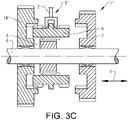
- Fig. 3C is a view of the vehicle transmission 1" in Fig. 3A , shown for the second gear state providing a second gear where the shifting fork 2 is positioned in the second predetermined position 5".
- the sleeve 9 and the gear wheel 7 are disengaged, and the sleeve 9 and the further gear wheel 14' are engaged and the sleeve 9 and the hub 8 are engaged, such that the further gear wheel 14' is rotationally locked to the first shaft 6 for providing the second gear.
- the gear wheel 14' can be engaged with another gear wheel of another shaft for transmitting torque between the shafts (not shown).
- Fig. 4A is a view of a further variant of the vehicle transmission 100 shown for the first gear state providing the first gear, where the shifting fork 20 is positioned in the first predetermined position 40.
- the sleeve 90 is engaged with a dog ring 70b of the gear wheel 70, and the sleeve 90 and the hub 80 are engaged.
- the sleeve 90 has splines arranged on an internal surface for engagement with splines arranged on an external surface of the hub 80 and for engagement with splines arranged on an external surface of the dog ring 70b.
- the further component is a park lock mechanism 140 arranged on the second shaft 17 for locking the second shaft 17 against rotation.
- the park lock mechanism 140 has a wheel 18 and a pawl 19 which can be engaged for locking the second shaft 17.
- the park lock state is not activated, i.e. the wheel 18 and the pawl 19 are disengaged from each other.
- Fig. 4B is a view of the vehicle transmission in Fig. 4A , shown for the second gear state providing the park lock state, where the shifting fork 20 is positioned in the second predetermined position 50.
- the sleeve 90 has been displaced in the axial direction 30 by means of the shifting fork 20 which has been moved from the first predetermined position 40 to the second predetermined position 50.
- the sleeve 90 is disengaged from the dog ring 70b of the gear wheel 70.
- an arm 150 of the shifting fork 20 has activated the park lock mechanism 140 such that the wheel 18 and the pawl 19 are engaged, thereby locking the second shaft 17.
Landscapes
- Engineering & Computer Science (AREA)
- General Engineering & Computer Science (AREA)
- Mechanical Engineering (AREA)
- Gear-Shifting Mechanisms (AREA)
Abstract
Description
- The invention relates to a transmission which comprises a shifting fork, where the transmission has a first gear state and a second gear state being selectable by means of the shifting fork, and the shifting fork is displaceable in an axial direction between a first predetermined position and a second predetermined position, where the first gear state is provided when the shifting fork is placed in the first predetermined position and the second gear state is provided when the shifting fork is placed in the second predetermined position.
- In today's transmissions for vehicles with electrical motors, some elements used in manual transmissions are not needed, and other has to be adapted to fit the new technologies. An important issue is the space limitation and how to reduce the size of the actuators of the transmission. One actuator system is usually used for shifting two different elements, trying to reduce the size and complexity of the actuator system. The shifting is performed from a neutral position where a sleeve is arranged centred relative to a hub. By movement of the sleeve from the centred neutral position to the left, one dog clutch is engaged and by movement of the sleeve from the centred neutral position to the right, another dog clutch is engaged. In this way, different gear states of the transmission can be achieved.
- An objective of the invention is to provide a transmission enabling the size and complexity of the transmission to be reduced.
- The objective is achieved by a transmission that comprises a shifting fork, where the transmission has a first gear state and a second gear state being selectable by means of the shifting fork, the shifting fork is displaceable in an axial direction between a first predetermined position and a second predetermined position, and the first gear state is provided when the shifting fork is placed in the first predetermined position and the second gear state is provided when the shifting fork is placed in the second predetermined position, where the first predetermined position and the second predetermined position are arranged one after the other without any further predetermined position providing a further selectable gear state arranged between the first predetermined position and the second predetermined position, and where the first gear state provides a first gear of the transmission and the second gear state provides a second gear or a park lock state of the transmission.
- The invention is based on the insight that by such a transmission, the shifting of two different elements, for example engagement of dog clutches, can be performed by movement of the shifting fork in one direction only. This enables a more compact design and also reduced shifting times. Instead of using a conventional solution where the sleeve has to be moved from a centred neutral position to the left for engagement of one element, and then back to the centred neutral position and further to the right for engagement of the other element, it is possible to achieve a transmission with a non-centred neutral position or without a neutral position.
- The first predetermined position and the second predetermined position are arranged after each other without any gear state selectable by the shifting fork therebetween. This will however not exclude that any intermediate "gear state" could take place temporarily during the transition between the first predetermined position and the second predetermined position, though such a "gear state" is not selectable and have no substantial impact on the torque provided by the transmission.
- The "first gear" and the "second gear" have different gear ratios providing different gears for the transmission. By the expression "park lock state" is meant that a shaft of the transmission is locked against rotation and thereby no torque can be transmitted by the transmission.
- The transmission can comprise a first shaft, a rotating member arranged on the first shaft, where the rotating member is rotationally journaled relative to the first shaft, and a hub arranged on the first shaft, where the hub is rotationally locked to the first shaft, and a sleeve moveable by means of the shifting fork in the axial direction, where the sleeve and the hub are engageable and rotationally locked to each other when engaged, and the sleeve and the rotating member are engageable and rotationally locked to each other when engaged, and preferably, in the first predetermined position of the shifting fork, the sleeve and the rotating member are engaged and the sleeve and the hub are engaged. Hereby, the first gear state can be achieved in an efficient way. The rotating member can be a gear wheel for instance.
- According to one embodiment, the shifting fork is placeable in a further predetermined position providing a further gear state being a neutral of the transmission, where the shifting fork is displaceable from the further predetermined position to the first predetermined position and further in the same direction from the first predetermined position to the second predetermined position. Hereby, a non-centred neutral position can be achieved, in addition to the first and second gear states.
- For achieving such a non-centred neutral position, optionally, the rotating member, such as a gear wheel idling in the non-centred neutral position, can be used, and further in the further predetermined position of the shifting fork, the sleeve and the rotating member are engaged and the sleeve and the hub are disengaged.
- For engagement of the sleeve and the rotating member, the sleeve can have splines arranged on an external surface of the sleeve for engagement with splines of the rotating member arranged on an internal surface of the rotating member. Further, for engagement of the sleeve and the hub, the sleeve can have splines arranged on an internal surface of the sleeve for engagement with splines of the hub arranged on an external surface of the hub. Optionally, by an undercut of the rotating member for receiving the sleeve, the design can be even less space consuming.
- According to a further embodiment, the transmission comprises a further component which is activated by the shifting fork in the second predetermined position of the shifting fork. Hereby, the second gear state can be achieved in a rational way where the further component can be arranged on the first shaft of the transmission or on a second shaft of the transmission.
- For example, the further component can be a park lock mechanism locking a shaft of the transmission against rotation when activated by the shifting fork, or the further component can be a further rotating member arranged on a shaft, such as a gear wheel, where the further rotating member is rotationally journaled relative to the shaft, and the further rotating member is rotationally locked to the shaft when activated by the shifting fork. This shaft to be locked by the parking lock mechanism or onto which the further rotating member is arranged, can be the first shaft or a second shaft of the transmission.
- According to a further embodiment, the first predetermined position of the shifting fork is a first end position where the shifting fork is not movable further away from the second predetermined position, and the second predetermined position of the shifting fork is a second end position where the shifting fork is not movable further away from the first predetermined position. Hereby, a compact transmission with a first gear state and a second gear state can be achieved.
- According to a further embodiment, the further predetermined position of the shifting fork is a first end position where the shifting fork is not movable further away from the second predetermined position, and the second predetermined position of the shifting fork is a second end position where the shifting fork is not movable further away from the further predetermined position. Hereby, a compact transmission with a first gear state, a second gear state and a non-centred neutral position can be achieved.
- Further advantages and advantageous features of the invention are disclosed in the following description and in the dependent claims.
- With reference to the appended drawings, below follows a more detailed description of embodiments of the invention cited as examples.
- In the drawings:
-
Fig. 1A is a view of the vehicle transmission shown for the first gear state providing the first gear, where the shifting fork is positioned in the first predetermined position, -
Fig. 1B is a view of the vehicle transmission inFig. 1A , shown for the second gear state providing the second gear or the park lock, where the shifting fork is positioned in the second predetermined position, -
Fig. 2A is a view of a variant of the vehicle transmission shown for the further gear state being a non-centred neutral, where the shifting fork is positioned in the further predetermined position, -
Fig. 2B is a view of the vehicle transmission inFig. 2A , shown for the first gear state providing the first gear, where the shifting fork is positioned in the first predetermined position, -
Fig. 2C is a view of the vehicle transmission inFig. 2A , shown for the second gear state providing the second gear or the park lock, where the shifting fork is positioned in the second predetermined position, -
Fig. 3A is a view of a further variant of the vehicle transmission, shown for the further gear state being a non-centred neutral, where the shifting fork is positioned in the further predetermined position, -
Fig. 3B is a view of the vehicle transmission inFig. 3A , shown for the first gear state providing the first gear, where the shifting fork is positioned in the first predetermined position, -
Fig. 3C is a view of the vehicle transmission inFig. 3A , shown for the second gear state providing the second gear, where the shifting fork is positioned in the second predetermined position, -
Fig. 4A is a view of a further variant the vehicle transmission, shown for the first gear state providing the first gear, where the shifting fork is positioned in the first predetermined position, and -
Fig. 4B is a view of the vehicle transmission inFig. 4A , shown for the second gear state providing the park lock state, where the shifting fork is positioned in the second predetermined position. -
Figs. 1A and 1B are schematic illustrations of avehicle transmission 1. Thetransmission 1 comprises a shiftingfork 2. The transmission has a first gear state and a second gear state which are selectable by means of the shiftingfork 2. The shiftingfork 2 is displaceable in anaxial direction 3 between a first predetermined position 4 (illustrated inFig. 1A ) providing the first gear state and a second predetermined position 5 (illustrated inFig. 1B ) providing the second gear state. - In other words; the first gear state is provided when the shifting
fork 2 is placed in the firstpredetermined position 4 and the second gear state is provided when the shiftingfork 2 is placed in the secondpredetermined position 5. Further, the firstpredetermined position 4 and the secondpredetermined position 5 are arranged one after the other without any further predetermined position providing a further selectable gear state arranged between the first predetermined position and the second predetermined position. The first gear state provides a first gear of the transmission and the second gear state provides a second gear or a park lock state of the transmission, i.e. none of the first gear state and the second gear state being a neutral position of the transmission. - The
transmission 1 comprises afirst shaft 6, a rotatingmember 7 arranged on thefirst shaft 6, where the rotatingmember 7 is rotationally journaled relative to thefirst shaft 6. The rotatingmember 7 is suitably a gear wheel. Thegear wheel 7 is a so called idling gear wheel which is journaled relative to thefirst shaft 6 but can be rotationally locked to thefirst shaft 6 through other components for transmitting torque between thegear wheel 7 and thefirst shaft 6. - In the example embodiment illustrated in
Figs. 1A and 1B , thetransmission 1 further comprises ahub 8 arranged on thefirst shaft 6, where thehub 8 is rotationally locked to thefirst shaft 6, and asleeve 9 moveable by means of the shiftingfork 2. Thesleeve 9 and thehub 8 are engageable with each other and are rotationally locked to each other when engaged. Thesleeve 9 and the rotatingmember 7 are engageable with each other and are rotationally locked to each other when engaged. Thesleeve 9 can havesplines 10 arranged on an external surface of the sleeve for engagement withsplines 11 of the rotatingmember 7 arranged on an internal surface of the rotating member. Further, thesleeve 9 can havesplines 12 arranged on an internal surface of the sleeve for engagement withsplines 13 of thehub 8 arranged on an external surface of the hub. In other words; thesleeve 9 is moveable in theaxial direction 3 by means of the shiftingfork 2 for engagement and disengagement relative to the rotatingmember 7 and thehub 8. - Optionally, the sleeve can have splines arranged on an internal surface for engagement with splines arranged on an external surface of the rotating member such as a dog ring of a gear wheel. See embodiment illustrated in
Figs. 4A and 4B . - In the first
predetermined position 4 of the shiftingfork 2, thesleeve 9 and the rotatingmember 7 are engaged and thesleeve 9 and thehub 8 are engaged, and thereby thegear wheel 7 is rotationally locked to thefirst shaft 6. For example, thegear wheel 7 can be engaged with another gear wheel of another shaft for transmitting torque between the shafts (not shown). - The
transmission 1 suitably comprises afurther component 14. Thefurther component 14 is schematically illustrated inFigs. 1A and 1B by a square box. InFig. 1B , the vehicle transmission inFig. 1A is shown for the second gear state where the shiftingfork 2 is positioned in the secondpredetermined position 5. - Although in the illustrated example, the
further component 14 is activated by the shiftingfork 2 in the second shiftingfork position 5, as schematically illustrated by anarm 15 of the shiftingfork 2 reaching thefurther component 14, in another embodiment thefurther component 14 can be activated by thesleeve 9 if thefurther component 14 is arranged on thefirst shaft 6. Thefurther component 14 can be arranged on thefirst shaft 6 of thetransmission 1 or arranged on a second shaft of the transmission. - Optionally, the
further component 14 can be directly activated by the shiftingfork 2 or via asleeve 9 or similar arranged on thefirst shaft 6 or another shaft. For example, thefurther component 14 can be a park lock mechanism locking a shaft of the transmission against rotation when activated by the shiftingfork 2. This shaft can be thefirst shaft 6 of thetransmission 1 or another shaft of the transmission. In another embodiment, the further component can be a further rotating member arranged on a shaft, such as a gear wheel, where the further rotating member is rotationally journaled relative to the shaft, and the further rotating member is rotationally locked to the shaft when activated by the shifting fork, for example via a sleeve. This shaft can be thefirst shaft 6 of thetransmission 1 or another shaft of the transmission. - In the second
predetermined position 5 illustrated inFig. 1B , thesleeve 9 has just been disengaged from thegear wheel 7, and thesleeve 9 and thegear wheel 7 are disengaged. In case activation of thefurther component 14 is not performed instantaneously, the shiftingfork 2 may have to be moved further away from thegear wheel 7 in theaxial direction 3 to reach the secondpredetermined position 5. Depending on the design of the transmission, optionally thesleeve 9 and thehub 8 can be engaged or disengaged in the secondpredetermined position 5, whereas thesleeve 9 and thegear wheel 7 always are disengaged in this position. - For example, if a second sleeve is to be brought into engagement with the further component for achieving the second gear state, the second sleeve may have to be displaced a certain distance while being engaged with the further component before reaching the second predetermined position, and in such a case the sleeve has to be disengaged from the gear wheel immediately before the second sleeve starts to engage the further component and remain disengaged during the further movement of the shifting fork towards the second predetermined position.
- Further, the first
predetermined position 4 of the shiftingfork 2 is suitably a first end position where the shiftingfork 2 is not movable further away from the secondpredetermined position 5, and the secondpredetermined position 5 of the shiftingfork 2 is suitably a second end position where the shiftingfork 2 is not movable further away from the firstpredetermined position 4. -
Figs. 2A, 2B and2C shows a variant of the vehicle transmission 1'. With reference to these figures, mainly different features of the transmission 1' relative to thetransmission 1 inFigs. 1A and 1B , will be described. For features not explicitly described, reference is made to the description ofFigs. 1A and 1B . - In
Fig. 2A , the transmission 1' is shown with the shiftingfork 2 positioned in a furtherpredetermined position 16. - In the further
predetermined position 16, thehub 8 and thesleeve 9 are disengaged, and thesleeve 9 and the rotatingmember 7 are engaged. As mentioned, the furtherpredetermined position 16 may constitute a neutral of the transmission 1'.Fig. 2A is a view of the vehicle transmission 1' shown for the further gear state which is a non-centred neutral where the shiftingfork 2 is positioned in the furtherpredetermined position 16, i.e. to the right inFig. 2A . In the further gear state, the journaledgear wheel 7 is idling, i.e. thegear wheel 7 is not rotationally locked to thefirst shaft 6. The shiftingfork 2 is displaceable from the furtherpredetermined position 16 to the first predetermined position 4' and further in the same direction from the first predetermined position 4' to the second predetermined position 5'. -
Fig. 2B is a view of the vehicle transmission 1' inFig. 2A , shown for the first gear state providing the first gear where the shiftingfork 2 is positioned in the first predetermined position 4'. This position of the shiftingfork 2 corresponds to the position illustrated for the transmission inFig. 1A . -
Fig. 2C is a view of the vehicle transmission 1' inFig. 2A , shown for the second gear state providing the second gear or the park lock state, where the shiftingfork 2 is positioned in the second predetermined position 5'. This position of the shiftingfork 2 corresponds to the position illustrated for the transmission inFig. 1B . - In addition, the further
predetermined position 16 of the shiftingfork 2 is a first end position where the shiftingfork 2 is not movable further away from the second predetermined position 5', and the second predetermined position 5' of the shiftingfork 2 is a second end position where the shiftingfork 2 is not movable further away from the furtherpredetermined position 16. - In
Figs. 3A, 3B , and3C a further variant of the transmission is illustrated. The further component is a further gear wheel 14' arranged on thefirst shaft 6. - In the same way as described for
Fig. 2A ,Fig. 3A is a view of thevehicle transmission 1" shown for the further gear state being a non-centred neutral, where the shiftingfork 2 is positioned in the further predetermined position 16', i.e. to the right inFig. 3A . In the further gear state, the journaledgear wheel 7 is idling, i.e. thegear wheel 7 is not rotationally locked to thefirst shaft 6. Thesleeve 9 and thegear wheel 7 are engaged, whereas thesleeve 9 and thehub 8 are disengaged. -
Fig. 3B is a view of thevehicle transmission 1" inFig. 3A , shown for the first gear state providing the first gear where the shiftingfork 2 is positioned in the firstpredetermined position 4". In the predeterminedfirst position 4" illustrated inFig. 3B , thehub 8 and thesleeve 9 are engaged, and thesleeve 9 and thegear wheel 7 are engaged, such that thegear wheel 7 is rotationally locked to thefirst shaft 6 for providing the first gear. For example, thegear wheel 7 can be engaged with another gear wheel of another shaft for transmitting torque between the shafts (not shown). -
Fig. 3C is a view of thevehicle transmission 1" inFig. 3A , shown for the second gear state providing a second gear where the shiftingfork 2 is positioned in the secondpredetermined position 5". In the secondpredetermined position 5" illustrated inFig. 3C , thesleeve 9 and thegear wheel 7 are disengaged, and thesleeve 9 and the further gear wheel 14' are engaged and thesleeve 9 and thehub 8 are engaged, such that the further gear wheel 14' is rotationally locked to thefirst shaft 6 for providing the second gear. For example, the gear wheel 14' can be engaged with another gear wheel of another shaft for transmitting torque between the shafts (not shown). -
Fig. 4A is a view of a further variant of thevehicle transmission 100 shown for the first gear state providing the first gear, where the shiftingfork 20 is positioned in the firstpredetermined position 40. Thesleeve 90 is engaged with adog ring 70b of thegear wheel 70, and thesleeve 90 and thehub 80 are engaged. Thesleeve 90 has splines arranged on an internal surface for engagement with splines arranged on an external surface of thehub 80 and for engagement with splines arranged on an external surface of thedog ring 70b. - The further component is a
park lock mechanism 140 arranged on thesecond shaft 17 for locking thesecond shaft 17 against rotation. Thepark lock mechanism 140 has awheel 18 and apawl 19 which can be engaged for locking thesecond shaft 17. In the firstpredetermined position 40 of the shiftingfork 20, the park lock state is not activated, i.e. thewheel 18 and thepawl 19 are disengaged from each other. -
Fig. 4B is a view of the vehicle transmission inFig. 4A , shown for the second gear state providing the park lock state, where the shiftingfork 20 is positioned in the secondpredetermined position 50. In comparison toFig. 4A , inFig. 4B thesleeve 90 has been displaced in theaxial direction 30 by means of the shiftingfork 20 which has been moved from the firstpredetermined position 40 to the secondpredetermined position 50. Thesleeve 90 is disengaged from thedog ring 70b of thegear wheel 70. Instead anarm 150 of the shiftingfork 20 has activated thepark lock mechanism 140 such that thewheel 18 and thepawl 19 are engaged, thereby locking thesecond shaft 17. - It is to be understood that the present invention is not limited to the embodiments described above and illustrated in the drawings; rather, the skilled person will recognize that many changes and modifications may be made within the scope of the appended claims.
Claims (15)
- A transmission (1) comprising a shifting fork (2), the transmission having a first gear state and a second gear state being selectable by means of the shifting fork (2), the shifting fork being displaceable in an axial direction (3) between a first predetermined position (4) and a second predetermined position (5), the first gear state being provided when the shifting fork (2) is placed in the first predetermined position (4) and the second gear state being provided when the shifting fork (2) is placed in the second predetermined position (5), the first predetermined position (4) and the second predetermined position (5) being arranged one after the other without any further predetermined position providing a further selectable gear state arranged between the first predetermined position and the second predetermined position, characterized in that the first gear state provides a first gear of the transmission (1) and the second gear state provides a second gear or a park lock state of the transmission (1).
- A transmission according to claim 1, characterized in that the transmission comprises a first shaft (6), a rotating member (7) arranged on the first shaft, the rotating member (7) being rotationally journaled relative to the first shaft (6), and a hub (8) arranged on the first shaft (6), the hub (8) being rotationally locked to the first shaft (6), and a sleeve (9) moveable by means of the shifting fork (2) in the axial direction (3), the sleeve (9) and the hub (8) being engageable and rotationally locked to each other when engaged, and the sleeve (9) and the rotating member (7) being engageable and rotationally locked to each other when engaged.
- A transmission according to claim 2, characterized in that the rotating member is a gearwheel (7).
- A transmission according to claim 2 or 3, characterized in that in the first predetermined position (4) of the shifting fork (2), the sleeve (9) and the rotating member (7) are engaged and the sleeve (9) and the hub (8) are engaged.
- A transmission according to any of claims 1-3, characterized in that the shifting fork (2) is placeable in a further predetermined position (16) providing a further gear state being a neutral of the transmission (1'), the shifting fork (2) being displaceable from the further predetermined position (16) to the first predetermined position (4') and further in the same direction from the first predetermined position (4') to the second predetermined position (5').
- A transmission according to claim 2 and 5, characterized in that in the further predetermined position (16) of the shifting fork (2), the sleeve (9) and the rotating member (7) are engaged and the sleeve (9) and the hub (8) are disengaged.
- A transmission according to any preceding claim, characterized in that the transmission (1) comprises a further component (14) which is activated by the shifting fork (2) in the second predetermined position (5) of the shifting fork (2).
- A transmission according to claim 7, characterized in that the further component is a further rotating member (14') arranged on a shaft (6), the further rotating member (14') being rotationally journaled relative to the shaft (6), and the further rotating member (14') being rotationally locked to the shaft (6) when activated by the shifting fork (2).
- A transmission according to claim 8, characterized in that the further rotating member is a gearwheel (14').
- A transmission according to claim 7, characterized in that the further component is a park lock mechanism (140) locking a shaft (17) of the transmission (1) against rotation when activated by the shifting fork (2).
- A transmission according to claims 2 and 7, characterized in that the further component (14') is arranged on the first shaft (6) of the transmission (1).
- A transmission according to claims 2 and 7, characterized in that the further component (140) is arranged on a second shaft (17) of the transmission (1).
- A transmission according to any of claims 2-4, characterized in that the sleeve (9) has splines (10) arranged on an external surface of the sleeve for engagement with splines (11) of the rotating member (7) arranged on an internal surface of the rotating member, and the sleeve (9) has splines (12) arranged on an internal surface of the sleeve for engagement with splines (13) of the hub (8) arranged on an external surface of the hub.
- A transmission according to claim 1, characterized in that the first predetermined position (4) of the shifting fork (2) is a first end position where the shifting fork is not movable further away from the second predetermined position (5), and the second predetermined position (5) of the shifting fork (2) is a second end position where the shifting fork is not movable further away from the first predetermined position (4).
- A transmission according to claim 5, characterized in that the further predetermined position (16) of the shifting fork (2) is a first end position where the shifting fork is not movable further away from the second predetermined position (5), and the second predetermined position (5) of the shifting fork (2) is a second end position where the shifting fork is not movable further away from the further predetermined position (16).
Priority Applications (4)
| Application Number | Priority Date | Filing Date | Title |
|---|---|---|---|
| EP20212033.3A EP4008932B1 (en) | 2020-12-04 | 2020-12-04 | A transmission |
| CN202180080612.4A CN116568949B (en) | 2020-12-04 | 2021-11-25 | transmission |
| PCT/CN2021/133063 WO2022116889A1 (en) | 2020-12-04 | 2021-11-25 | A transmission |
| US18/138,056 US12163586B2 (en) | 2020-12-04 | 2023-04-22 | Transmission |
Applications Claiming Priority (1)
| Application Number | Priority Date | Filing Date | Title |
|---|---|---|---|
| EP20212033.3A EP4008932B1 (en) | 2020-12-04 | 2020-12-04 | A transmission |
Publications (2)
| Publication Number | Publication Date |
|---|---|
| EP4008932A1 true EP4008932A1 (en) | 2022-06-08 |
| EP4008932B1 EP4008932B1 (en) | 2023-11-15 |
Family
ID=73726744
Family Applications (1)
| Application Number | Title | Priority Date | Filing Date |
|---|---|---|---|
| EP20212033.3A Active EP4008932B1 (en) | 2020-12-04 | 2020-12-04 | A transmission |
Country Status (4)
| Country | Link |
|---|---|
| US (1) | US12163586B2 (en) |
| EP (1) | EP4008932B1 (en) |
| CN (1) | CN116568949B (en) |
| WO (1) | WO2022116889A1 (en) |
Families Citing this family (1)
| Publication number | Priority date | Publication date | Assignee | Title |
|---|---|---|---|---|
| CN118387059B (en) * | 2024-03-29 | 2026-04-03 | 比亚迪股份有限公司 | A parking device, parking control method, storage medium, system, and vehicle for a vehicle. |
Citations (5)
| Publication number | Priority date | Publication date | Assignee | Title |
|---|---|---|---|---|
| US4431073A (en) * | 1981-12-03 | 1984-02-14 | Fairfield Manufacturing Co., Inc. | Two speed final drive gear box |
| CN101463901A (en) * | 2007-12-17 | 2009-06-24 | 比亚迪股份有限公司 | Parking and shifting actuating mechanism |
| DE102013108300A1 (en) * | 2013-08-01 | 2015-02-05 | Thyssenkrupp Presta Teccenter Ag | Gearbox for a drive unit of an electric vehicle and method for operating the gearbox |
| JP6380272B2 (en) * | 2015-07-23 | 2018-08-29 | トヨタ車体株式会社 | Electric vehicle, 2-speed transmission mechanism and in-wheel motor |
| US20200070653A1 (en) * | 2018-09-04 | 2020-03-05 | Ford Global Technologies, Llc | Ranged Power Take-Off Unit For Transaxle |
Family Cites Families (12)
| Publication number | Priority date | Publication date | Assignee | Title |
|---|---|---|---|---|
| FR2811051B1 (en) | 2000-06-30 | 2002-10-04 | Renault | CONTROL DEVICE FOR CONNECTING A CRAWLESS GEAR ON A SHAFT AND THIS SHAFT, IN PARTICULAR FOR A MOTOR VEHICLE GEARBOX |
| DE10224357A1 (en) | 2002-05-29 | 2003-12-11 | Daimler Chrysler Ag | Device for switching a toothed wheel gear changing box comprises an adjusting slide arranged on a switching sleeve and sliding toward the main shaft, and a spring element acting between the first stop and the adjusting slide |
| US6824491B2 (en) * | 2003-03-25 | 2004-11-30 | Power Network Industry Co., Ltd. | Power transmission device with automatic speed switching mechanism |
| CN101377229B (en) * | 2007-08-29 | 2012-12-19 | 苏州宝时得电动工具有限公司 | Variable speed tool and its variable speed control method |
| CN201093036Y (en) * | 2007-08-31 | 2008-07-30 | 苏州宝时得电动工具有限公司 | Speed changing tool |
| CN101637901B (en) * | 2008-07-31 | 2011-12-07 | 苏州宝时得电动工具有限公司 | Speed changer |
| CN102562959A (en) * | 2010-12-30 | 2012-07-11 | 苏州宝时得电动工具有限公司 | Speed change tool |
| CN103998828B (en) * | 2012-12-12 | 2015-08-05 | 丰田自动车株式会社 | vehicle power transmission |
| DE102013108736A1 (en) | 2013-08-12 | 2015-02-12 | Hoerbiger Antriebstechnik Holding Gmbh | Claw connection for a vehicle transmission |
| DE112014003878B4 (en) * | 2013-08-23 | 2023-08-03 | American Axle & Manufacturing, Inc. | Power transmission component with double fork actuator |
| DE102014114006A1 (en) * | 2014-09-26 | 2016-03-31 | Getrag Ford Transmissions Gmbh | Manual transmission for a motor vehicle |
| DE102018118548A1 (en) * | 2018-07-31 | 2020-02-06 | Schaeffler Technologies AG & Co. KG | Two-speed gearbox for an electrically drivable motor vehicle |
-
2020
- 2020-12-04 EP EP20212033.3A patent/EP4008932B1/en active Active
-
2021
- 2021-11-25 WO PCT/CN2021/133063 patent/WO2022116889A1/en not_active Ceased
- 2021-11-25 CN CN202180080612.4A patent/CN116568949B/en active Active
-
2023
- 2023-04-22 US US18/138,056 patent/US12163586B2/en active Active
Patent Citations (5)
| Publication number | Priority date | Publication date | Assignee | Title |
|---|---|---|---|---|
| US4431073A (en) * | 1981-12-03 | 1984-02-14 | Fairfield Manufacturing Co., Inc. | Two speed final drive gear box |
| CN101463901A (en) * | 2007-12-17 | 2009-06-24 | 比亚迪股份有限公司 | Parking and shifting actuating mechanism |
| DE102013108300A1 (en) * | 2013-08-01 | 2015-02-05 | Thyssenkrupp Presta Teccenter Ag | Gearbox for a drive unit of an electric vehicle and method for operating the gearbox |
| JP6380272B2 (en) * | 2015-07-23 | 2018-08-29 | トヨタ車体株式会社 | Electric vehicle, 2-speed transmission mechanism and in-wheel motor |
| US20200070653A1 (en) * | 2018-09-04 | 2020-03-05 | Ford Global Technologies, Llc | Ranged Power Take-Off Unit For Transaxle |
Also Published As
| Publication number | Publication date |
|---|---|
| WO2022116889A1 (en) | 2022-06-09 |
| CN116568949B (en) | 2026-04-10 |
| CN116568949A (en) | 2023-08-08 |
| EP4008932B1 (en) | 2023-11-15 |
| US12163586B2 (en) | 2024-12-10 |
| US20230265921A1 (en) | 2023-08-24 |
Similar Documents
| Publication | Publication Date | Title |
|---|---|---|
| US11746898B2 (en) | Actuator arrangement for electric drive | |
| US20110167957A1 (en) | Automatic dual-clutch transmission | |
| EP2886911B1 (en) | Spring loaded shift actuator assembly having a retaining mechanism | |
| US20130192398A1 (en) | Dual Clutch Transmission And Dual Clutch Actuators Thereof | |
| EP3467353A1 (en) | A method for controlling a transmission | |
| JP2016113152A (en) | Two-speed transfer case with non-synchronized range shift mechanism and on-the-move range shift control system | |
| US12163586B2 (en) | Transmission | |
| US5711186A (en) | Reverse synchronizer mechanism of manual transmission for a vehicle | |
| US2433428A (en) | Torque responsive clutch | |
| US6647816B1 (en) | Electrically actuated synchronizer for a vehicle transmission | |
| GB2213884A (en) | Manual transmission with synchronized gear engagement | |
| EP0299930B1 (en) | Motor vehicle gearbox with a device for synchronised engagement of reverse | |
| US12305752B2 (en) | Transmission | |
| CN210600140U (en) | Gear shifting mechanism, power system and electric vehicle | |
| EP3670970B1 (en) | A transmission for a vehicle | |
| EP1828632A2 (en) | Synchronizer for a transmission | |
| CN111946756A (en) | Decoupling system for a vehicle transmission, vehicle transmission and vehicle | |
| JPS645158Y2 (en) | ||
| US11701966B2 (en) | Driveline component including multi-function actuator | |
| CN211259610U (en) | parking lock | |
| JP2002500327A (en) | Automotive gearbox | |
| JPH0324899Y2 (en) | ||
| GB2214247A (en) | An automotive transmission with synchronized gear engagement | |
| JPH0533806Y2 (en) | ||
| WO2010123436A1 (en) | Vehicle comprising a transmission device with pto shaft |
Legal Events
| Date | Code | Title | Description |
|---|---|---|---|
| PUAI | Public reference made under article 153(3) epc to a published international application that has entered the european phase |
Free format text: ORIGINAL CODE: 0009012 |
|
| STAA | Information on the status of an ep patent application or granted ep patent |
Free format text: STATUS: REQUEST FOR EXAMINATION WAS MADE |
|
| 17P | Request for examination filed |
Effective date: 20201204 |
|
| AK | Designated contracting states |
Kind code of ref document: A1 Designated state(s): AL AT BE BG CH CY CZ DE DK EE ES FI FR GB GR HR HU IE IS IT LI LT LU LV MC MK MT NL NO PL PT RO RS SE SI SK SM TR |
|
| STAA | Information on the status of an ep patent application or granted ep patent |
Free format text: STATUS: EXAMINATION IS IN PROGRESS |
|
| 17Q | First examination report despatched |
Effective date: 20230201 |
|
| GRAP | Despatch of communication of intention to grant a patent |
Free format text: ORIGINAL CODE: EPIDOSNIGR1 |
|
| STAA | Information on the status of an ep patent application or granted ep patent |
Free format text: STATUS: GRANT OF PATENT IS INTENDED |
|
| INTG | Intention to grant announced |
Effective date: 20230609 |
|
| GRAS | Grant fee paid |
Free format text: ORIGINAL CODE: EPIDOSNIGR3 |
|
| GRAA | (expected) grant |
Free format text: ORIGINAL CODE: 0009210 |
|
| STAA | Information on the status of an ep patent application or granted ep patent |
Free format text: STATUS: THE PATENT HAS BEEN GRANTED |
|
| AK | Designated contracting states |
Kind code of ref document: B1 Designated state(s): AL AT BE BG CH CY CZ DE DK EE ES FI FR GB GR HR HU IE IS IT LI LT LU LV MC MK MT NL NO PL PT RO RS SE SI SK SM TR |
|
| REG | Reference to a national code |
Ref country code: CH Ref legal event code: EP Ref country code: GB Ref legal event code: FG4D |
|
| REG | Reference to a national code |
Ref country code: DE Ref legal event code: R096 Ref document number: 602020021021 Country of ref document: DE |
|
| REG | Reference to a national code |
Ref country code: IE Ref legal event code: FG4D |
|
| REG | Reference to a national code |
Ref country code: LT Ref legal event code: MG9D |
|
| REG | Reference to a national code |
Ref country code: NL Ref legal event code: MP Effective date: 20231115 |
|
| PG25 | Lapsed in a contracting state [announced via postgrant information from national office to epo] |
Ref country code: IS Free format text: LAPSE BECAUSE OF FAILURE TO SUBMIT A TRANSLATION OF THE DESCRIPTION OR TO PAY THE FEE WITHIN THE PRESCRIBED TIME-LIMIT Effective date: 20240315 |
|
| PG25 | Lapsed in a contracting state [announced via postgrant information from national office to epo] |
Ref country code: LT Free format text: LAPSE BECAUSE OF FAILURE TO SUBMIT A TRANSLATION OF THE DESCRIPTION OR TO PAY THE FEE WITHIN THE PRESCRIBED TIME-LIMIT Effective date: 20231115 |
|
| REG | Reference to a national code |
Ref country code: AT Ref legal event code: MK05 Ref document number: 1632053 Country of ref document: AT Kind code of ref document: T Effective date: 20231115 |
|
| PG25 | Lapsed in a contracting state [announced via postgrant information from national office to epo] |
Ref country code: NL Free format text: LAPSE BECAUSE OF FAILURE TO SUBMIT A TRANSLATION OF THE DESCRIPTION OR TO PAY THE FEE WITHIN THE PRESCRIBED TIME-LIMIT Effective date: 20231115 |
|
| PG25 | Lapsed in a contracting state [announced via postgrant information from national office to epo] |
Ref country code: AT Free format text: LAPSE BECAUSE OF FAILURE TO SUBMIT A TRANSLATION OF THE DESCRIPTION OR TO PAY THE FEE WITHIN THE PRESCRIBED TIME-LIMIT Effective date: 20231115 |
|
| PG25 | Lapsed in a contracting state [announced via postgrant information from national office to epo] |
Ref country code: ES Free format text: LAPSE BECAUSE OF FAILURE TO SUBMIT A TRANSLATION OF THE DESCRIPTION OR TO PAY THE FEE WITHIN THE PRESCRIBED TIME-LIMIT Effective date: 20231115 |
|
| PG25 | Lapsed in a contracting state [announced via postgrant information from national office to epo] |
Ref country code: NL Free format text: LAPSE BECAUSE OF FAILURE TO SUBMIT A TRANSLATION OF THE DESCRIPTION OR TO PAY THE FEE WITHIN THE PRESCRIBED TIME-LIMIT Effective date: 20231115 Ref country code: LT Free format text: LAPSE BECAUSE OF FAILURE TO SUBMIT A TRANSLATION OF THE DESCRIPTION OR TO PAY THE FEE WITHIN THE PRESCRIBED TIME-LIMIT Effective date: 20231115 Ref country code: IS Free format text: LAPSE BECAUSE OF FAILURE TO SUBMIT A TRANSLATION OF THE DESCRIPTION OR TO PAY THE FEE WITHIN THE PRESCRIBED TIME-LIMIT Effective date: 20240315 Ref country code: ES Free format text: LAPSE BECAUSE OF FAILURE TO SUBMIT A TRANSLATION OF THE DESCRIPTION OR TO PAY THE FEE WITHIN THE PRESCRIBED TIME-LIMIT Effective date: 20231115 Ref country code: BG Free format text: LAPSE BECAUSE OF FAILURE TO SUBMIT A TRANSLATION OF THE DESCRIPTION OR TO PAY THE FEE WITHIN THE PRESCRIBED TIME-LIMIT Effective date: 20240215 Ref country code: AT Free format text: LAPSE BECAUSE OF FAILURE TO SUBMIT A TRANSLATION OF THE DESCRIPTION OR TO PAY THE FEE WITHIN THE PRESCRIBED TIME-LIMIT Effective date: 20231115 Ref country code: PT Free format text: LAPSE BECAUSE OF FAILURE TO SUBMIT A TRANSLATION OF THE DESCRIPTION OR TO PAY THE FEE WITHIN THE PRESCRIBED TIME-LIMIT Effective date: 20240315 |
|
| PG25 | Lapsed in a contracting state [announced via postgrant information from national office to epo] |
Ref country code: SE Free format text: LAPSE BECAUSE OF FAILURE TO SUBMIT A TRANSLATION OF THE DESCRIPTION OR TO PAY THE FEE WITHIN THE PRESCRIBED TIME-LIMIT Effective date: 20231115 Ref country code: RS Free format text: LAPSE BECAUSE OF FAILURE TO SUBMIT A TRANSLATION OF THE DESCRIPTION OR TO PAY THE FEE WITHIN THE PRESCRIBED TIME-LIMIT Effective date: 20231115 Ref country code: PL Free format text: LAPSE BECAUSE OF FAILURE TO SUBMIT A TRANSLATION OF THE DESCRIPTION OR TO PAY THE FEE WITHIN THE PRESCRIBED TIME-LIMIT Effective date: 20231115 Ref country code: NO Free format text: LAPSE BECAUSE OF FAILURE TO SUBMIT A TRANSLATION OF THE DESCRIPTION OR TO PAY THE FEE WITHIN THE PRESCRIBED TIME-LIMIT Effective date: 20240215 Ref country code: LV Free format text: LAPSE BECAUSE OF FAILURE TO SUBMIT A TRANSLATION OF THE DESCRIPTION OR TO PAY THE FEE WITHIN THE PRESCRIBED TIME-LIMIT Effective date: 20231115 Ref country code: HR Free format text: LAPSE BECAUSE OF FAILURE TO SUBMIT A TRANSLATION OF THE DESCRIPTION OR TO PAY THE FEE WITHIN THE PRESCRIBED TIME-LIMIT Effective date: 20231115 |
|
| PG25 | Lapsed in a contracting state [announced via postgrant information from national office to epo] |
Ref country code: DK Free format text: LAPSE BECAUSE OF FAILURE TO SUBMIT A TRANSLATION OF THE DESCRIPTION OR TO PAY THE FEE WITHIN THE PRESCRIBED TIME-LIMIT Effective date: 20231115 |
|
| PG25 | Lapsed in a contracting state [announced via postgrant information from national office to epo] |
Ref country code: CZ Free format text: LAPSE BECAUSE OF FAILURE TO SUBMIT A TRANSLATION OF THE DESCRIPTION OR TO PAY THE FEE WITHIN THE PRESCRIBED TIME-LIMIT Effective date: 20231115 |
|
| PG25 | Lapsed in a contracting state [announced via postgrant information from national office to epo] |
Ref country code: SK Free format text: LAPSE BECAUSE OF FAILURE TO SUBMIT A TRANSLATION OF THE DESCRIPTION OR TO PAY THE FEE WITHIN THE PRESCRIBED TIME-LIMIT Effective date: 20231115 |
|
| PG25 | Lapsed in a contracting state [announced via postgrant information from national office to epo] |
Ref country code: SM Free format text: LAPSE BECAUSE OF FAILURE TO SUBMIT A TRANSLATION OF THE DESCRIPTION OR TO PAY THE FEE WITHIN THE PRESCRIBED TIME-LIMIT Effective date: 20231115 Ref country code: SK Free format text: LAPSE BECAUSE OF FAILURE TO SUBMIT A TRANSLATION OF THE DESCRIPTION OR TO PAY THE FEE WITHIN THE PRESCRIBED TIME-LIMIT Effective date: 20231115 Ref country code: RO Free format text: LAPSE BECAUSE OF FAILURE TO SUBMIT A TRANSLATION OF THE DESCRIPTION OR TO PAY THE FEE WITHIN THE PRESCRIBED TIME-LIMIT Effective date: 20231115 Ref country code: IT Free format text: LAPSE BECAUSE OF FAILURE TO SUBMIT A TRANSLATION OF THE DESCRIPTION OR TO PAY THE FEE WITHIN THE PRESCRIBED TIME-LIMIT Effective date: 20231115 Ref country code: EE Free format text: LAPSE BECAUSE OF FAILURE TO SUBMIT A TRANSLATION OF THE DESCRIPTION OR TO PAY THE FEE WITHIN THE PRESCRIBED TIME-LIMIT Effective date: 20231115 Ref country code: DK Free format text: LAPSE BECAUSE OF FAILURE TO SUBMIT A TRANSLATION OF THE DESCRIPTION OR TO PAY THE FEE WITHIN THE PRESCRIBED TIME-LIMIT Effective date: 20231115 Ref country code: CZ Free format text: LAPSE BECAUSE OF FAILURE TO SUBMIT A TRANSLATION OF THE DESCRIPTION OR TO PAY THE FEE WITHIN THE PRESCRIBED TIME-LIMIT Effective date: 20231115 |
|
| REG | Reference to a national code |
Ref country code: CH Ref legal event code: PL |
|
| REG | Reference to a national code |
Ref country code: DE Ref legal event code: R097 Ref document number: 602020021021 Country of ref document: DE |
|
| PG25 | Lapsed in a contracting state [announced via postgrant information from national office to epo] |
Ref country code: LU Free format text: LAPSE BECAUSE OF NON-PAYMENT OF DUE FEES Effective date: 20231204 |
|
| PG25 | Lapsed in a contracting state [announced via postgrant information from national office to epo] |
Ref country code: MC Free format text: LAPSE BECAUSE OF FAILURE TO SUBMIT A TRANSLATION OF THE DESCRIPTION OR TO PAY THE FEE WITHIN THE PRESCRIBED TIME-LIMIT Effective date: 20231115 |
|
| REG | Reference to a national code |
Ref country code: BE Ref legal event code: MM Effective date: 20231231 |
|
| PG25 | Lapsed in a contracting state [announced via postgrant information from national office to epo] |
Ref country code: MC Free format text: LAPSE BECAUSE OF FAILURE TO SUBMIT A TRANSLATION OF THE DESCRIPTION OR TO PAY THE FEE WITHIN THE PRESCRIBED TIME-LIMIT Effective date: 20231115 Ref country code: LU Free format text: LAPSE BECAUSE OF NON-PAYMENT OF DUE FEES Effective date: 20231204 |
|
| PLBE | No opposition filed within time limit |
Free format text: ORIGINAL CODE: 0009261 |
|
| STAA | Information on the status of an ep patent application or granted ep patent |
Free format text: STATUS: NO OPPOSITION FILED WITHIN TIME LIMIT |
|
| REG | Reference to a national code |
Ref country code: IE Ref legal event code: MM4A |
|
| PG25 | Lapsed in a contracting state [announced via postgrant information from national office to epo] |
Ref country code: IE Free format text: LAPSE BECAUSE OF NON-PAYMENT OF DUE FEES Effective date: 20231204 |
|
| PG25 | Lapsed in a contracting state [announced via postgrant information from national office to epo] |
Ref country code: BE Free format text: LAPSE BECAUSE OF NON-PAYMENT OF DUE FEES Effective date: 20231231 |
|
| PG25 | Lapsed in a contracting state [announced via postgrant information from national office to epo] |
Ref country code: CH Free format text: LAPSE BECAUSE OF NON-PAYMENT OF DUE FEES Effective date: 20231231 |
|
| 26N | No opposition filed |
Effective date: 20240819 |
|
| PG25 | Lapsed in a contracting state [announced via postgrant information from national office to epo] |
Ref country code: SI Free format text: LAPSE BECAUSE OF FAILURE TO SUBMIT A TRANSLATION OF THE DESCRIPTION OR TO PAY THE FEE WITHIN THE PRESCRIBED TIME-LIMIT Effective date: 20231115 |
|
| PG25 | Lapsed in a contracting state [announced via postgrant information from national office to epo] |
Ref country code: SI Free format text: LAPSE BECAUSE OF FAILURE TO SUBMIT A TRANSLATION OF THE DESCRIPTION OR TO PAY THE FEE WITHIN THE PRESCRIBED TIME-LIMIT Effective date: 20231115 Ref country code: IE Free format text: LAPSE BECAUSE OF NON-PAYMENT OF DUE FEES Effective date: 20231204 Ref country code: CH Free format text: LAPSE BECAUSE OF NON-PAYMENT OF DUE FEES Effective date: 20231231 Ref country code: BE Free format text: LAPSE BECAUSE OF NON-PAYMENT OF DUE FEES Effective date: 20231231 |
|
| PG25 | Lapsed in a contracting state [announced via postgrant information from national office to epo] |
Ref country code: FI Free format text: LAPSE BECAUSE OF FAILURE TO SUBMIT A TRANSLATION OF THE DESCRIPTION OR TO PAY THE FEE WITHIN THE PRESCRIBED TIME-LIMIT Effective date: 20231115 |
|
| PG25 | Lapsed in a contracting state [announced via postgrant information from national office to epo] |
Ref country code: CY Free format text: LAPSE BECAUSE OF FAILURE TO SUBMIT A TRANSLATION OF THE DESCRIPTION OR TO PAY THE FEE WITHIN THE PRESCRIBED TIME-LIMIT; INVALID AB INITIO Effective date: 20201204 |
|
| PG25 | Lapsed in a contracting state [announced via postgrant information from national office to epo] |
Ref country code: HU Free format text: LAPSE BECAUSE OF FAILURE TO SUBMIT A TRANSLATION OF THE DESCRIPTION OR TO PAY THE FEE WITHIN THE PRESCRIBED TIME-LIMIT; INVALID AB INITIO Effective date: 20201204 |
|
| PG25 | Lapsed in a contracting state [announced via postgrant information from national office to epo] |
Ref country code: GR Free format text: LAPSE BECAUSE OF FAILURE TO SUBMIT A TRANSLATION OF THE DESCRIPTION OR TO PAY THE FEE WITHIN THE PRESCRIBED TIME-LIMIT; INVALID AB INITIO Effective date: 20201204 |
|
| PG25 | Lapsed in a contracting state [announced via postgrant information from national office to epo] |
Ref country code: TR Free format text: LAPSE BECAUSE OF FAILURE TO SUBMIT A TRANSLATION OF THE DESCRIPTION OR TO PAY THE FEE WITHIN THE PRESCRIBED TIME-LIMIT Effective date: 20231115 |
|
| PGFP | Annual fee paid to national office [announced via postgrant information from national office to epo] |
Ref country code: GB Payment date: 20251104 Year of fee payment: 6 |
|
| PGFP | Annual fee paid to national office [announced via postgrant information from national office to epo] |
Ref country code: FR Payment date: 20251117 Year of fee payment: 6 |
|
| PGFP | Annual fee paid to national office [announced via postgrant information from national office to epo] |
Ref country code: DE Payment date: 20251222 Year of fee payment: 6 |