EP4008895A1 - Root portion for a wind turbine blade - Google Patents
Root portion for a wind turbine blade Download PDFInfo
- Publication number
- EP4008895A1 EP4008895A1 EP20383056.7A EP20383056A EP4008895A1 EP 4008895 A1 EP4008895 A1 EP 4008895A1 EP 20383056 A EP20383056 A EP 20383056A EP 4008895 A1 EP4008895 A1 EP 4008895A1
- Authority
- EP
- European Patent Office
- Prior art keywords
- wind turbine
- turbine blade
- root portion
- support element
- support
- Prior art date
- Legal status (The legal status is an assumption and is not a legal conclusion. Google has not performed a legal analysis and makes no representation as to the accuracy of the status listed.)
- Granted
Links
Images




Classifications
-
- F—MECHANICAL ENGINEERING; LIGHTING; HEATING; WEAPONS; BLASTING
- F03—MACHINES OR ENGINES FOR LIQUIDS; WIND, SPRING, OR WEIGHT MOTORS; PRODUCING MECHANICAL POWER OR A REACTIVE PROPULSIVE THRUST, NOT OTHERWISE PROVIDED FOR
- F03D—WIND MOTORS
- F03D13/00—Assembly, mounting or commissioning of wind motors; Arrangements specially adapted for transporting wind motor components
- F03D13/40—Arrangements or methods specially adapted for transporting wind motor components
-
- F—MECHANICAL ENGINEERING; LIGHTING; HEATING; WEAPONS; BLASTING
- F03—MACHINES OR ENGINES FOR LIQUIDS; WIND, SPRING, OR WEIGHT MOTORS; PRODUCING MECHANICAL POWER OR A REACTIVE PROPULSIVE THRUST, NOT OTHERWISE PROVIDED FOR
- F03D—WIND MOTORS
- F03D1/00—Wind motors with rotation axis substantially parallel to the air flow entering the rotor
- F03D1/06—Rotors
- F03D1/065—Rotors characterised by their construction elements
- F03D1/0658—Arrangements for fixing wind-engaging parts to a hub
-
- F—MECHANICAL ENGINEERING; LIGHTING; HEATING; WEAPONS; BLASTING
- F03—MACHINES OR ENGINES FOR LIQUIDS; WIND, SPRING, OR WEIGHT MOTORS; PRODUCING MECHANICAL POWER OR A REACTIVE PROPULSIVE THRUST, NOT OTHERWISE PROVIDED FOR
- F03D—WIND MOTORS
- F03D1/00—Wind motors with rotation axis substantially parallel to the air flow entering the rotor
- F03D1/06—Rotors
- F03D1/065—Rotors characterised by their construction elements
- F03D1/0675—Rotors characterised by their construction elements of the blades
-
- F—MECHANICAL ENGINEERING; LIGHTING; HEATING; WEAPONS; BLASTING
- F03—MACHINES OR ENGINES FOR LIQUIDS; WIND, SPRING, OR WEIGHT MOTORS; PRODUCING MECHANICAL POWER OR A REACTIVE PROPULSIVE THRUST, NOT OTHERWISE PROVIDED FOR
- F03D—WIND MOTORS
- F03D13/00—Assembly, mounting or commissioning of wind motors; Arrangements specially adapted for transporting wind motor components
- F03D13/10—Assembly of wind motors; Arrangements for erecting wind motors
-
- F—MECHANICAL ENGINEERING; LIGHTING; HEATING; WEAPONS; BLASTING
- F03—MACHINES OR ENGINES FOR LIQUIDS; WIND, SPRING, OR WEIGHT MOTORS; PRODUCING MECHANICAL POWER OR A REACTIVE PROPULSIVE THRUST, NOT OTHERWISE PROVIDED FOR
- F03D—WIND MOTORS
- F03D13/00—Assembly, mounting or commissioning of wind motors; Arrangements specially adapted for transporting wind motor components
- F03D13/40—Arrangements or methods specially adapted for transporting wind motor components
- F03D13/401—Arrangements or methods specially adapted for transporting wind motor components for transporting or storing blades
-
- F—MECHANICAL ENGINEERING; LIGHTING; HEATING; WEAPONS; BLASTING
- F03—MACHINES OR ENGINES FOR LIQUIDS; WIND, SPRING, OR WEIGHT MOTORS; PRODUCING MECHANICAL POWER OR A REACTIVE PROPULSIVE THRUST, NOT OTHERWISE PROVIDED FOR
- F03D—WIND MOTORS
- F03D80/00—Details, components or accessories not provided for in groups F03D1/00 - F03D17/00
-
- F—MECHANICAL ENGINEERING; LIGHTING; HEATING; WEAPONS; BLASTING
- F05—INDEXING SCHEMES RELATING TO ENGINES OR PUMPS IN VARIOUS SUBCLASSES OF CLASSES F01-F04
- F05B—INDEXING SCHEME RELATING TO WIND, SPRING, WEIGHT, INERTIA OR LIKE MOTORS, TO MACHINES OR ENGINES FOR LIQUIDS COVERED BY SUBCLASSES F03B, F03D AND F03G
- F05B2230/00—Manufacture
- F05B2230/60—Assembly methods
- F05B2230/61—Assembly methods using auxiliary equipment for lifting or holding
-
- F—MECHANICAL ENGINEERING; LIGHTING; HEATING; WEAPONS; BLASTING
- F05—INDEXING SCHEMES RELATING TO ENGINES OR PUMPS IN VARIOUS SUBCLASSES OF CLASSES F01-F04
- F05B—INDEXING SCHEME RELATING TO WIND, SPRING, WEIGHT, INERTIA OR LIKE MOTORS, TO MACHINES OR ENGINES FOR LIQUIDS COVERED BY SUBCLASSES F03B, F03D AND F03G
- F05B2240/00—Components
- F05B2240/20—Rotors
- F05B2240/21—Rotors for wind turbines
- F05B2240/221—Rotors for wind turbines with horizontal axis
-
- F—MECHANICAL ENGINEERING; LIGHTING; HEATING; WEAPONS; BLASTING
- F05—INDEXING SCHEMES RELATING TO ENGINES OR PUMPS IN VARIOUS SUBCLASSES OF CLASSES F01-F04
- F05B—INDEXING SCHEME RELATING TO WIND, SPRING, WEIGHT, INERTIA OR LIKE MOTORS, TO MACHINES OR ENGINES FOR LIQUIDS COVERED BY SUBCLASSES F03B, F03D AND F03G
- F05B2260/00—Function
- F05B2260/02—Transport, e.g. specific adaptations or devices for conveyance
-
- Y—GENERAL TAGGING OF NEW TECHNOLOGICAL DEVELOPMENTS; GENERAL TAGGING OF CROSS-SECTIONAL TECHNOLOGIES SPANNING OVER SEVERAL SECTIONS OF THE IPC; TECHNICAL SUBJECTS COVERED BY FORMER USPC CROSS-REFERENCE ART COLLECTIONS [XRACs] AND DIGESTS
- Y02—TECHNOLOGIES OR APPLICATIONS FOR MITIGATION OR ADAPTATION AGAINST CLIMATE CHANGE
- Y02E—REDUCTION OF GREENHOUSE GAS [GHG] EMISSIONS, RELATED TO ENERGY GENERATION, TRANSMISSION OR DISTRIBUTION
- Y02E10/00—Energy generation through renewable energy sources
- Y02E10/70—Wind energy
- Y02E10/72—Wind turbines with rotation axis in wind direction
Definitions
- blade-specific support cradles may be provided on respective transport and/or storage means. Those blade-specific support cradles are adapted to the outer shape of the blade (at the root and/or tip portion) and are intended to receive the blade under a pre-defined orientation. However, blade-specific support cradles are expensive and require extensive retooling of respective the transport and/or storage means, in case different types of turbine blades shall be transported or stored.
- the coupling flange 11 may be a circular flange. Further, the coupling flange 11 may be made from two symmetric halves being welded together.
- the support planes 16a, 16b are defined in this example by flat surfaces provided on the support elements 13a, 13b.
- Each of the support elements 13 may be associated with a respective support plane 16.
- a support plane may be defined by at least two of different support elements.
- the portions protruding beyond the annular mounting surface define an orientation of the mounting flange 11 relative to a storage surface 200.
Landscapes
- Engineering & Computer Science (AREA)
- Life Sciences & Earth Sciences (AREA)
- Sustainable Development (AREA)
- Sustainable Energy (AREA)
- Chemical & Material Sciences (AREA)
- Combustion & Propulsion (AREA)
- Mechanical Engineering (AREA)
- General Engineering & Computer Science (AREA)
- Wind Motors (AREA)
Abstract
Description
- The present disclosure relates to a root portion for a wind turbine blade, to a wind turbine blade comprising such a root portion and to methods for positioning, and for transporting and storing said wind turbine blade.
- Modern wind turbines are commonly used to supply electricity into the electrical grid. Wind turbines of this kind generally comprise a tower and a rotor arranged on the tower. The rotor, which typically comprises a hub and a plurality of blades, is set into rotation under the influence of the wind on the blades. Said rotation generates a torque that is normally transmitted through a rotor shaft to a generator, either directly or through the use of a gearbox. This way, the generator produces electricity which can be supplied to the electrical grid.
- The storage and transport of wind turbine blades has become more and more of a challenging task due to the general tendency to increase the size of modern wind turbines and a corresponding increase in the size and weight of the blades. Blades of modern wind turbines may be more than 70 or 80 meters, or even more than 100 meters long. Before installation, and after manufacture, the wind turbine blades may have to be temporarily stored and further transported to the installation site. Once the blades have been transported to the installation site or to the wind park which may be offshore, the wind turbine blades may be hoisted towards the rotor hub.
- •In the art, blade-specific support cradles may be provided on respective transport and/or storage means. Those blade-specific support cradles are adapted to the outer shape of the blade (at the root and/or tip portion) and are intended to receive the blade under a pre-defined orientation. However, blade-specific support cradles are expensive and require extensive retooling of respective the transport and/or storage means, in case different types of turbine blades shall be transported or stored.
- Further, in the art, circular-bow-shaped support cradles are used. When using said circular-bow-shaped support cradles the blade can be received under substantially any angular orientation. However, since the blades may have a significant curvature, including twist and sweep, and in order to be able to correctly support a tip portion of a blade, the blade root needs to be positioned in the cradle at a given orientation rather precisely.
- As the root portion of a turbine blade typically has a substantially circular shape, it is difficult to place the root portion of the turbine blade exactly under a pre-defined angular orientation, to achieve the desired angular orientation of the tip portion. This is particularly, if the tolerances for orientating the tip portion must be set low, to avoid transporting and/or storing damages.
- The present disclosure provides a root portion for a wind turbine blade, a turbine blade and a method for transporting and/or storing a wind turbine blade that resolve the aforementioned disadvantages, at least partially.
- In a first aspect of the present disclosure, a root portion for a wind turbine blade, comprising a coupling flange, configured for coupling the root portion to a hub of a wind turbine, and at least one support element, fixedly attached to the coupling flange, wherein the at least one support element defines a support plane for contacting a transport and/or storing surface.
- The term support element as used throughout the present disclosure should be regarded as any structure that because of material properties, structure, or shape contributes to the formation of a support plane. The transport and/or storing surface is typically provided on a transport and/or storing means, that is different from the root portion and the wind turbine blade. The transport and/or storing surface as used throughout the present disclosure can be any surface, particularly flat surface, that is supports the root portion and/or the wind turbine blade during transport and storing, as it comes into contact with the support plane, defined by the at least one support element.
- Since the support element is fixedly attached to the coupling flange, the support plane is fixed with respect to the root of the blade. A blade may thus be placed or positioned on a support element, a fixture or the floor or ground, and the support plane ensures that this occurs in a given orientation of the blade, thereby making sure that also a tip portion may be suitable supported if necessary.
- In another aspect, a wind turbine blade comprising a blade root, the blade root having a coupling flange, configured for coupling the root to a hub of a wind turbine, the coupling flange comprising one or more support elements, which define a substantially flat support area for contacting a transport and/or storing surface.
- In accordance with this aspect, a flat support area is thus incorporated in the wind turbine blade, such that a blade cam simply be placed on a floor or ground area with a known orientation of the blade.
- In yet a further aspect, a method for positioning a wind turbine blade is provided. The method comprises providing a wind turbine blade comprising a blade root mounting flange defining an annular mounting surface for mounting the wind turbine blade to a hub of a wind turbine, the blade root mounting flange comprising one or more portions protruding beyond the annular mounting surface. The method comprises placing the wind turbine blade on a storing surface so as to be supported by the portions of the mounting flange protruding beyond the annular mounting flange.
- The terms coupling flange and mounting flange are used interchangeably herein. The term coupling flange or mounting flange is used to denote a part of a root portion of a wind turbine blade which is used to attached to another component of a wind turbine, and in particular, the wind turbine hub or a pitch bearing of the wind turbine hub.
- In the following, aspects of the present disclosure are described in detail, with respect to the accompanying figures.
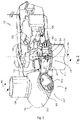
- Fig. 1
- schematically illustrates a perspective view of one example of a wind turbine;
- Fig. 2
- schematically illustrates a simplified, internal view of one example of the nacelle of the wind turbine of the
Figure 1 ; - Fig. 3
- schematically illustrates an example of a root portion of a wind turbine blade;
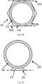
- Figs. 4A - 4D
- schematically illustrate further examples of a root portion with different support elements;
- Fig. 5
- schematically illustrates an example of a wind turbine blade; and
- Fig. 6
- schematically illustrates a flow diagram of an example of a method for positioning a wind turbine blade.
- Reference now will be made in detail to embodiments of the invention, one or more examples of which are illustrated in the drawings. Each example is provided by way of explanation of the invention, not as a limitation of the invention. In fact, it will be apparent to those skilled in the art that various modifications and variations can be made in the present invention without departing from the scope or spirit of the invention. For instance, features illustrated or described as part of one embodiment can be used with another embodiment to yield a still further embodiment. Thus, it is intended that the present invention covers such modifications and variations as come within the scope of the appended claims and their equivalents.
-
Figure 1 illustrates a perspective view of one example of awind turbine 160. As shown, thewind turbine 160 includes atower 170 extending from asupport surface 150, anacelle 161 mounted on thetower 170, and arotor 115 coupled to thenacelle 161. Therotor 115 includes arotatable hub 110 and at least onerotor blade 120 coupled to and extending outwardly from thehub 110. For example, in the illustrated embodiment, therotor 115 includes threerotor blades 120. However, in an alternative embodiment, therotor 115 may include more or less than threerotor blades 120. Eachrotor blade 120 may be spaced about thehub 110 to facilitate rotating therotor 115 to enable kinetic energy to be transferred from the wind into usable mechanical energy, and subsequently, electrical energy. For instance, thehub 110 may be rotatably coupled to an electric generator 162 (Figure 2 ) positioned within thenacelle 161 to permit electrical energy to be produced. -
Figure 2 illustrates a simplified, internal view of one example of thenacelle 161 of thewind turbine 160 of theFigure 1 . As shown, thegenerator 162 may be disposed within thenacelle 161. In general, thegenerator 162 may be coupled to therotor 115 of thewind turbine 160 for generating electrical power from the rotational energy generated by therotor 115. For example, therotor 115 may include amain rotor shaft 163 coupled to thehub 110 for rotation therewith. Thegenerator 162 may then be coupled to therotor shaft 163 such that rotation of therotor shaft 163 drives thegenerator 162. For instance, in the illustrated embodiment, thegenerator 162 includes agenerator shaft 166 rotatably coupled to therotor shaft 163 through agearbox 164. - It should be appreciated that the
rotor shaft 163,gearbox 164, andgenerator 162 may generally be supported within thenacelle 161 by a support frame orbedplate 165 positioned atop thewind turbine tower 170. - The
nacelle 161 is rotatably coupled to thetower 170 through theyaw system 20 in such a way that thenacelle 161 is able to rotate about a yaw axis YA. Theyaw system 20 comprises a yaw bearing having two bearing components configured to rotate with respect to the other. Thetower 170 is coupled to one of the bearing components and the bedplate orsupport frame 165 of thenacelle 161 is coupled to the other bearing component. Theyaw system 20 comprises anannular gear 21 and a plurality of yaw drives 22 with amotor 23, agearbox 24 and apinion 25 for meshing with theannular gear 21 for rotating one of the bearing components with respect to the other. -
Blades 120 are coupled to thehub 110 with a pitch bearing 100 in between theblade 120 and thehub 110. Thepitch bearing 100 comprises an inner ring and an outer ring. A wind turbine blade may be attached either at the inner bearing ring or at the outer bearing ring, whereas the hub is connected at the other. Ablade 120 may perform a relative rotational movement with respect to thehub 110 when apitch system 107 is actuated. The inner bearing ring may therefore perform a rotational movement with respect to the outer bearing ring. Thepitch system 107 ofFigure 2 comprises apinion 108 that meshes with anannular gear 109 provided on the inner bearing ring to set the wind turbine blade into rotation around a pitch axis PA. -
Figure 3 illustrates an example of aroot portion 10 for awind turbine blade 120 comprising acoupling flange 11. Thecoupling flange 11 is configured for coupling the root portion to ahub 110 of a wind turbine 160 (e.g. via a pitch bearing). Thecoupling flange 11 may carry a plurality of fasteners which may be adapted to mate with corresponding fasteners, such as holes or similar, at thehub 110 of thewind turbine 160. The fasteners may be e.g. pins, bolts or studs. These fasteners may be introduced particularly in corresponding holes of a pitch bearing ring. Another pitch bearing may be attached to the hub. - The
coupling flange 11 may be a circular flange. Further, thecoupling flange 11 may be made from two symmetric halves being welded together. - The at least one
support element support plane surface 200. Thesupport plane support element support element 13. If thesupport plane 16a is substantially flat, a root portion of a wind turbine blade may be positioned e.g. on a floor or ground surface without the need of any specific cradle or any specifically prepared storage or transportation tool. - As
Figure 3 illustrates, theroot portion 10 may comprise an outer circumference and the at least one support element may radially extend form said outer circumference of the coupling flange. - Further, the
root portion 10 may comprise at least onefastening element 12, including a transportation means and/or handling means 18. The at least onefastening element 12 radially extends from the outer circumference of thecoupling flange 11. - The
root portion 10 in the example ofFigure 3 further comprises twosupport elements support element 13 is being fixedly attached to thecoupling flange 11. Other examples may comprisedifferent support elements 13 and arrangements thereof, as e.g. shown inFigs. 4A to 4D . Thesupport elements 13 may in some examples be equally distributed around the outer circumference of thecoupling flange 11 and may further comprise at least one transportation feature and/or handlingfeature 14. - The transportation feature and/or handling
feature fastening element 12 and/or thesupport elements - The support element(s) 13 may be made from the same material as the
coupling flange 11. The material of the support element(s) and the coupling flange may be metallic, such as steel or other metal-based alloys. Further, the support element(s) 13 and thecoupling flange 11 may be formed integrally, e.g. by casting. In a further aspect, thecoupling flange 11 and the support element(s) may be cut, milled or otherwise machined from a single part, e.g. a metallic base element. Further, the support element(s) may be attached to theflange portion 11 by welding. - The
support elements Figure 3 define twosupport planes first support plane 16a of therespective support element 13a is contacting a transport and/or storingsurface 200. Asecond support plane 16b is arranged opposite to the first support plane (substantially parallel thereto) and is presently not in use. - The support planes 16a, 16b are defined in this example by flat surfaces provided on the
support elements different support elements 13 exist, wherein at least onesupport element 13 defines asupport plane 16 for contacting a transport and/or storingsurface 200. Each of thesupport elements 13 may be associated with arespective support plane 16. Further, a support plane may be defined by at least two of different support elements. By defining more than one support plane, and particularly at diametrically opposition positions, blades may be positioned or stored in different orientations. In particular, blades may be stacked in different orientations. - The
support element 13a may further define anangle 15 of thecoupling flange 11 around acentral axis 17 of thecoupling flange 11, relative to the transport and/or storingsurface 200, as thesupport plane 16a is in contact with the respective transport and/or storingsurface 200. -
Figures 4A-4D schematically illustrate further examples ofroot portions 10 and wind turbine blades incorporatingsupport elements 13. - In the example of
figure 4A , asingle support element 13 may be incorporated in the coupling flange of the root of the wind turbine blade. Thesupport element 13 in this example defines a substantially flat support plane upon which the wind turbine blade can rest. The support plane substantially coincides, at a point, with an outer circumference of the annular mountingsurface 11 of the flange. In other words, the support plane is tangential to an outer circumference of thecoupling flange 11. -
Figure 4B illustrates another example, in which the mounting flange includingsupport elements 13 is symmetric with respect to a horizontal axis passing through a center of the root when the blade is supported on itssupport plane 16a. In this particular example, the mounting flange is rotationally symmetrical. An outer circumference of the mounting flange in this example is hexagonal. - At least two
support planes - In the example of
figure 4C , the mounting flange comprises aprotrusion 13 protruding beyond annular mounting surface. Asupport 13 with a substantially triangular shape is provided. Theroot portion 10 of the wind turbine blade may be supported bysupport plane 16, forming the base of the triangular shape. - As illustrated in another example in
Figure 4D thesupport plane 16 of thesupport element 13 may be defined by a first point of support on afirst support element 13a and a second point of support provided on asecond support element 13b, which is different from the first support element. -
Figure 5 illustrates awind turbine blade 120 comprising ablade root 10 having a coupling flange, configured for coupling the root to a hub of a wind turbine. The coupling flange comprises one or more support elements, which define a substantially flat support area for contacting a transport and/or storing surface. - As may be seen in
figure 5 , thewind turbine blade 120 may comprise a first support element at a first position, and a second support element at a second position, which is diametrically opposite to the first position. - In some examples, the support elements may be integrally formed with the coupling flange. In some examples, the blade may further comprise a plate, partially closing off an inside of the wind turbine blade. Such a plate may stiffen and reinforce a blade root portion. The plate may comprise one or more manholes allowing access to an interior of the blade.
- A blade shell generally defines a leading edge, trailing edge, pressure surface and suction surface may be made of composite material, such as glass fibre composite, carbon fibre composite, or combinations thereof. Further, the mounting flange may be attached to the blade shell as part of a resin infusion or injection process. After curing takes places, the blade shell of composite material is then firmly attached to the coupling flange. The coupling flange includes the
aforementioned support elements 13. - The blade may comprise multiple segments that can be coupled to form a respective
wind turbine blade 120. The length of theblade portion 20 may be in the range from 30 m to 150 m, or in the range from 50 m to 120 m, or in the range from 60 m to 110 m. -
Figure 6 illustrates a flow diagram of amethod 2000 for positioning awind turbine blade 120. The method comprises providing at block 2100 a wind turbine blade including a blade root mounting flange defining an annular mounting surface for mounting thewind turbine blade 120 to a hub of a wind turbine. The blade root mounting flange comprising one or more portions protruding beyond the annular mounting surface. - As noted before, the blade root mounting flange may be attached indirectly to the hub of the wind turbine through a pitch bearing.
- The method then comprises placing, at
block 2200, thewind turbine blade 120 on a storingsurface 200 so as to be supported by the portions of the mounting flange protruding beyond the annular mounting flange. - In some examples, the portions protruding beyond the annular mounting surface define an orientation of the mounting
flange 11 relative to astorage surface 200. - The method may further comprise, at
block 2300, providing a tip portion of the wind turbine blade on a tip cradle. If the protrusions outside the annular mounting surface of the blade root define a support plane, it can be ensured that the tip portion of the blade is correctly orientated such that it can be positioned within a cradle for supporting the tip portion. - The method may then comprise, at
block 2400, transporting the blade, or storing and optionally subsequently transporting the blade. Any suitable transportation device might be used such as e.g. a crane, a truck, a low-loader, a trailer, a towing vehicle a sea container and/or a ship. - After arrival at a site, the blade may be installed on a hub of the wind turbine. The protrusions extending beyond the annular mounting flange of the root do not need to be removed prior to operation of the wind turbine.
- In any of the herein disclosed examples, the wind turbine blades may be, but does not need to be, a segmented blade. A segmented blade is a blade in which a root portion and a tip portion (and optionally further blade portions) are manufactured and transported separately. The root portion may then be attached to the tip portion before installation.
- In any of the herein disclosed examples, the blades may directly or indirectly be attached to a wind turbine blade hub. An indirect attachment may herein be understood as an attachment with another element in between the blade and the hub, in particular a pitch bearing. More particularly, a pitch bearing may comprise an inner and an outer bearing ring with one or more rows of rolling elements (rollers, balls or other) in between. One of the outer and inner bearing rings maybe attached to the hub, and the other of the inner and outer bearing ring may be attached to the wind turbine blade.
- Even though some features of fasteners, lifting attachments etc. for handling, and hoisting were only illustrated with respect to
figure 3 , it should be clear that the same or similar features can also be included in any of the examples offigures 4 and5 . - This written description uses examples to disclose the invention, including the preferred embodiments, and also to enable any person skilled in the art to practice the invention, including making and using any devices or systems and performing any incorporated methods. The patentable scope of the invention is defined by the claims, and may include other examples that occur to those skilled in the art. Such other examples are intended to be within the scope of the claims if they have fastening elements that do not differ from the literal language of the claims, or if they include equivalent fastening elements with insubstantial differences from the literal languages of the claims. Aspects from the various embodiments described, as well as other known equivalents for each such aspects, can be mixed and matched by one of ordinary skill in the art to construct additional embodiments and techniques in accordance with principles of this application. If reference signs related to drawings are placed in parentheses in a claim, they are solely for attempting to increase the intelligibility of the claim, and shall not be construed as limiting the scope of the claim.
-
- 10
- root portion
- 11
- coupling flange
- 12
- fastening element including a transportation and/or handling feature
- 13
- support element
- 13a
- first support element
- 13b
- second support element
- 14
- transportation and/or handling feature
- 15
- rotation angle
- 16
- support plane
- 16a
- first support plane
- 16b
- second support plane
- 17
- central axis
- 18
- transportation and/or handling means
- 19
- attachment line
- 20
- blade portion
- 100
- pitch bearing
- 107
- pitch system
- 108
- pinion
- 109
- annular gear
- 110
- hub of a wind turbine
- 115
- rotor
- 120
- wind turbine blade (rotor blade)
- 150
- support surface
- 160
- wind turbine
- 161
- nacelle
- 162
- generator
- 163
- rotor shaft
- 164
- gearbox
- 165
- support frame
- 166
- generator shaft
- 170
- tower
- 200
- transport and/or storing surface
- 2000
- a method for positioning a wind turbine blade
- 2100
- providing a wind turbine blade
- 2200
- placing the wind turbine blade on a transport and/or storing surface
- 2300
- supporting tip portion of blade in tip cradle
- 2400
- storing and/or transporting the wind turbine blade
Claims (15)
- A root portion (10) for a wind turbine blade (120), comprising:a coupling flange (11), configured for coupling the root portion to a hub (110) of a wind turbine (160), andat least one support element (13), fixedly attached to the coupling flange (11), whereinthe at least one support element (13) defines a support plane (16) for contacting a transport and/or storing surface (200).
- The root portion (10) for a wind turbine blade (120) according to claim 1, wherein the coupling flange comprises an outer circumference, and wherein
the support element (13) radially extends from the outer circumference of the coupling flange (11). - The root portion (10) for a wind turbine blade (120) according to claim 1 or 2, wherein the support plane (16) of the support element (13) is defined by a flat surface provided on the support element (13).
- The root portion (10) for a wind turbine blade (120) according to claim 3, wherein the flat surface is tangential to the outer circumference of the coupling flange (11).
- The root portion (10) for a wind turbine blade (120) according to any of claims 1 - 4, wherein the support plane of the support element (13) is defined by at least one first point of support provided on a first support element (13a) and a second point of support provided on a second support element (13b), which is different from the first support element.
- The root portion (10) for a wind turbine blade (120) according to any of claims 1 - 5, wherein the root portion comprises multiple support elements (13a, 13b),
wherein at least two support elements (13a, 13b) are disposed diametrically opposite to each other at the outer circumference of the coupling flange (11), or
wherein the support elements (13) are equally distributed around the outer circumference of the coupling flange (11). - The root portion (10) for a wind turbine blade (120) according to any of claims 1 - 6, wherein the support element (13) comprises one or more holes configured for attachment to a lifting tool.
- The root portion (10) for a wind turbine blade (120) according to any of claims 1 - 7, wherein the support element (13) is made from the same material as the coupling flange (11).
- The root portion (10) for a wind turbine blade (120) according to any of claims 1 - 8, wherein the at least one support element (13) is welded to the coupling flange (11).
- The root portion (10) for a wind turbine blade (120) according to any of claims 1 - 9, wherein the at least one support element (13) and the coupling flange (11) are integrally formed.
- The root portion (10) for a wind turbine blade (120) according to any of claims 1 - 10, further comprising at least one fastener fixedly attached to the coupling flange and radially extending from the outer circumference of the coupling flange (11), and
optionally wherein the fastener (14, 18) includes at least one of the following: a through hole, an undercut, a rail, a counterpart for a gripping tool, a frictional connection means, a threaded hole and/or a groove. - A wind turbine blade (120) comprising a blade root according to any of claims 1 - 11.
- A method (2000) for positioning a wind turbine blade (120), the method comprising:providing (2100) a wind turbine blade (120) comprising a blade root mounting flange defining an annular mounting surface for mounting the wind turbine blade (120) to a hub of a wind turbine, the blade root mounting flange comprising one or more portions protruding beyond the annular mounting surface andplacing (2200) the wind turbine blade (120) on a storing surface (200) so as to be supported by the portions of the mounting flange protruding beyond the annular mounting flange.
- The method according to claim 13, wherein the portions protruding beyond the annular mounting surface define an orientation of the mounting flange (11) around a central axis (17), relative to a storage surface (200).
- The method according to claim 13 or 14, further comprising providing a tip portion of the wind turbine blade on a tip cradle.
Priority Applications (7)
| Application Number | Priority Date | Filing Date | Title |
|---|---|---|---|
| PL20383056.7T PL4008895T3 (en) | 2020-12-03 | 2020-12-03 | Root portion for a wind turbine blade |
| EP20383056.7A EP4008895B1 (en) | 2020-12-03 | 2020-12-03 | Root portion for a wind turbine blade |
| ES20383056T ES3055964T3 (en) | 2020-12-03 | 2020-12-03 | Root portion for a wind turbine blade |
| JP2021183806A JP7792234B2 (en) | 2020-12-03 | 2021-11-11 | Root sections for wind turbine blades |
| KR1020210166902A KR20220078493A (en) | 2020-12-03 | 2021-11-29 | Root portion for a wind turbine blade |
| US17/539,411 US11835026B2 (en) | 2020-12-03 | 2021-12-01 | Root portion for a wind turbine blade |
| CN202111471652.XA CN114593008A (en) | 2020-12-03 | 2021-12-03 | Root portion for a wind turbine blade |
Applications Claiming Priority (1)
| Application Number | Priority Date | Filing Date | Title |
|---|---|---|---|
| EP20383056.7A EP4008895B1 (en) | 2020-12-03 | 2020-12-03 | Root portion for a wind turbine blade |
Publications (2)
| Publication Number | Publication Date |
|---|---|
| EP4008895A1 true EP4008895A1 (en) | 2022-06-08 |
| EP4008895B1 EP4008895B1 (en) | 2025-09-10 |
Family
ID=73834414
Family Applications (1)
| Application Number | Title | Priority Date | Filing Date |
|---|---|---|---|
| EP20383056.7A Active EP4008895B1 (en) | 2020-12-03 | 2020-12-03 | Root portion for a wind turbine blade |
Country Status (7)
| Country | Link |
|---|---|
| US (1) | US11835026B2 (en) |
| EP (1) | EP4008895B1 (en) |
| JP (1) | JP7792234B2 (en) |
| KR (1) | KR20220078493A (en) |
| CN (1) | CN114593008A (en) |
| ES (1) | ES3055964T3 (en) |
| PL (1) | PL4008895T3 (en) |
Cited By (1)
| Publication number | Priority date | Publication date | Assignee | Title |
|---|---|---|---|---|
| CN115822878A (en) * | 2022-12-20 | 2023-03-21 | 易事特智能化系统集成有限公司 | Wind power generation wind wheel installation and alignment device and alignment method thereof |
Citations (4)
| Publication number | Priority date | Publication date | Assignee | Title |
|---|---|---|---|---|
| EP2458200A1 (en) * | 2010-11-30 | 2012-05-30 | Alstom Wind, S.L.U. | Wind turbine rotor comprising a pitch bearing mechanism and a method of repair therefore |
| EP2981717A1 (en) * | 2013-03-25 | 2016-02-10 | Zülau A/S | Support element with an adjustable attachment |
| EP3543524A1 (en) * | 2018-03-19 | 2019-09-25 | LM Wind Power International Technology II ApS | Handling of a wind turbine blade |
| US20200332771A1 (en) * | 2017-12-21 | 2020-10-22 | Lm Wind Power International Technology Ii Aps | Method and system for transporting wind turbine blades |
Family Cites Families (8)
| Publication number | Priority date | Publication date | Assignee | Title |
|---|---|---|---|---|
| DE102006055091A1 (en) * | 2006-11-21 | 2008-05-29 | Repower Systems Ag | Bulkhead of a wind turbine |
| PT2416986E (en) | 2009-04-09 | 2015-02-12 | Wobben Properties Gmbh | Transport device |
| PL3026258T3 (en) | 2010-08-12 | 2019-12-31 | Lm Wp Patent Holding A/S | Transportation and storage system for wind turbine blades |
| EP2778403A1 (en) * | 2013-03-13 | 2014-09-17 | Siemens Aktiengesellschaft | Bearing with a supporting element and method of supporting a first ring of a bearing |
| DK2808540T3 (en) * | 2013-05-31 | 2016-04-18 | Siemens Ag | System and method for moving a wind turbine rotor blade |
| US20150369209A1 (en) | 2014-06-23 | 2015-12-24 | General Electric Company | Rotor blade transportation system |
| US11286914B2 (en) * | 2016-06-30 | 2022-03-29 | Vestas Wind Systems A/S | Nacelle base frame assembly for a wind turbine |
| ES2966488T3 (en) * | 2019-06-03 | 2024-04-22 | Lm Wind Power As | Bulkhead for a wind turbine blade and procedure for installing a bulkhead on a wind turbine blade |
-
2020
- 2020-12-03 PL PL20383056.7T patent/PL4008895T3/en unknown
- 2020-12-03 EP EP20383056.7A patent/EP4008895B1/en active Active
- 2020-12-03 ES ES20383056T patent/ES3055964T3/en active Active
-
2021
- 2021-11-11 JP JP2021183806A patent/JP7792234B2/en active Active
- 2021-11-29 KR KR1020210166902A patent/KR20220078493A/en active Pending
- 2021-12-01 US US17/539,411 patent/US11835026B2/en active Active
- 2021-12-03 CN CN202111471652.XA patent/CN114593008A/en active Pending
Patent Citations (4)
| Publication number | Priority date | Publication date | Assignee | Title |
|---|---|---|---|---|
| EP2458200A1 (en) * | 2010-11-30 | 2012-05-30 | Alstom Wind, S.L.U. | Wind turbine rotor comprising a pitch bearing mechanism and a method of repair therefore |
| EP2981717A1 (en) * | 2013-03-25 | 2016-02-10 | Zülau A/S | Support element with an adjustable attachment |
| US20200332771A1 (en) * | 2017-12-21 | 2020-10-22 | Lm Wind Power International Technology Ii Aps | Method and system for transporting wind turbine blades |
| EP3543524A1 (en) * | 2018-03-19 | 2019-09-25 | LM Wind Power International Technology II ApS | Handling of a wind turbine blade |
Cited By (1)
| Publication number | Priority date | Publication date | Assignee | Title |
|---|---|---|---|---|
| CN115822878A (en) * | 2022-12-20 | 2023-03-21 | 易事特智能化系统集成有限公司 | Wind power generation wind wheel installation and alignment device and alignment method thereof |
Also Published As
| Publication number | Publication date |
|---|---|
| CN114593008A (en) | 2022-06-07 |
| EP4008895B1 (en) | 2025-09-10 |
| PL4008895T3 (en) | 2026-01-19 |
| JP7792234B2 (en) | 2025-12-25 |
| JP2022089164A (en) | 2022-06-15 |
| US20220178345A1 (en) | 2022-06-09 |
| ES3055964T3 (en) | 2026-02-17 |
| KR20220078493A (en) | 2022-06-10 |
| US11835026B2 (en) | 2023-12-05 |
Similar Documents
| Publication | Publication Date | Title |
|---|---|---|
| US9394886B2 (en) | System and method for re-indexing a pitch bearing of a wind turbine | |
| EP2500564B1 (en) | Gear box, seal and cover arrangements | |
| EP2302215A1 (en) | Wind-driven generator and construction method thereof | |
| EP2538079A2 (en) | Unitary support frame for use in wind turbines | |
| US20100135808A1 (en) | Systems and methods for assembling a pitch assembly for use in a wind turbine | |
| US20130180199A1 (en) | Flange connection for a wind turbine and method of connecting parts of a wind turbine | |
| US9909561B2 (en) | Rotor assembly for a wind turbine and method for mounting a blade to the rotor assembly | |
| US10502193B2 (en) | Repair method for a gearbox assembly of a wind turbine | |
| JP2014167273A (en) | Wind turbine generator | |
| EP3282122A1 (en) | Adapters for wind turbine refurbishment | |
| CN102400862B (en) | Method for assembling impeller of wind power generator unit | |
| CN112585351B (en) | Counterweight assembly for use during installation of a single blade of a wind turbine | |
| US11835026B2 (en) | Root portion for a wind turbine blade | |
| EP3719310A1 (en) | Rotor turning device for a wind turbine rotor | |
| US20190136626A1 (en) | External ladder assembly for wind turbine nacelle | |
| US10472792B2 (en) | Tower flange for a wind turbine | |
| US9777705B2 (en) | Method for re-indexing a pitch bearing of a wind turbine | |
| US12149132B2 (en) | Segmented generator, generator segment and wind turbine, and also method for preparing transportation of a segmented generator, and for transporting and installing the same, and also method for assembling a wind turbine | |
| US12497952B2 (en) | Couplings and auxiliary components for wind turbines, and associated methods | |
| CN121701426A (en) | Method for replacing bearing and wind driven generator |
Legal Events
| Date | Code | Title | Description |
|---|---|---|---|
| PUAI | Public reference made under article 153(3) epc to a published international application that has entered the european phase |
Free format text: ORIGINAL CODE: 0009012 |
|
| STAA | Information on the status of an ep patent application or granted ep patent |
Free format text: STATUS: THE APPLICATION HAS BEEN PUBLISHED |
|
| AK | Designated contracting states |
Kind code of ref document: A1 Designated state(s): AL AT BE BG CH CY CZ DE DK EE ES FI FR GB GR HR HU IE IS IT LI LT LU LV MC MK MT NL NO PL PT RO RS SE SI SK SM TR |
|
| STAA | Information on the status of an ep patent application or granted ep patent |
Free format text: STATUS: REQUEST FOR EXAMINATION WAS MADE |
|
| 17P | Request for examination filed |
Effective date: 20221208 |
|
| RBV | Designated contracting states (corrected) |
Designated state(s): AL AT BE BG CH CY CZ DE DK EE ES FI FR GB GR HR HU IE IS IT LI LT LU LV MC MK MT NL NO PL PT RO RS SE SI SK SM TR |
|
| P01 | Opt-out of the competence of the unified patent court (upc) registered |
Effective date: 20230529 |
|
| STAA | Information on the status of an ep patent application or granted ep patent |
Free format text: STATUS: EXAMINATION IS IN PROGRESS |
|
| 17Q | First examination report despatched |
Effective date: 20240927 |
|
| REG | Reference to a national code |
Ref country code: DE Ref legal event code: R079 Free format text: PREVIOUS MAIN CLASS: F03D0001060000 Ipc: F03D0013400000 Ref document number: 602020058452 Country of ref document: DE |
|
| GRAP | Despatch of communication of intention to grant a patent |
Free format text: ORIGINAL CODE: EPIDOSNIGR1 |
|
| STAA | Information on the status of an ep patent application or granted ep patent |
Free format text: STATUS: GRANT OF PATENT IS INTENDED |
|
| RIC1 | Information provided on ipc code assigned before grant |
Ipc: F03D 13/40 20160101AFI20250401BHEP |
|
| RAP3 | Party data changed (applicant data changed or rights of an application transferred) |
Owner name: GENERAL ELECTRIC RENOVABLES ESPANA S.L. |
|
| INTG | Intention to grant announced |
Effective date: 20250416 |
|
| GRAS | Grant fee paid |
Free format text: ORIGINAL CODE: EPIDOSNIGR3 |
|
| GRAA | (expected) grant |
Free format text: ORIGINAL CODE: 0009210 |
|
| STAA | Information on the status of an ep patent application or granted ep patent |
Free format text: STATUS: THE PATENT HAS BEEN GRANTED |
|
| AK | Designated contracting states |
Kind code of ref document: B1 Designated state(s): AL AT BE BG CH CY CZ DE DK EE ES FI FR GB GR HR HU IE IS IT LI LT LU LV MC MK MT NL NO PL PT RO RS SE SI SK SM TR |
|
| REG | Reference to a national code |
Ref country code: GB Ref legal event code: FG4D |
|
| REG | Reference to a national code |
Ref country code: CH Ref legal event code: EP |
|
| REG | Reference to a national code |
Ref country code: DE Ref legal event code: R096 Ref document number: 602020058452 Country of ref document: DE |
|
| REG | Reference to a national code |
Ref country code: IE Ref legal event code: FG4D |
|
| REG | Reference to a national code |
Ref country code: NL Ref legal event code: FP |
|
| PGFP | Annual fee paid to national office [announced via postgrant information from national office to epo] |
Ref country code: NL Payment date: 20251119 Year of fee payment: 6 |
|
| PGFP | Annual fee paid to national office [announced via postgrant information from national office to epo] |
Ref country code: DE Payment date: 20251126 Year of fee payment: 6 |
|
| PGFP | Annual fee paid to national office [announced via postgrant information from national office to epo] |
Ref country code: GB Payment date: 20251119 Year of fee payment: 6 |
|
| PG25 | Lapsed in a contracting state [announced via postgrant information from national office to epo] |
Ref country code: NO Free format text: LAPSE BECAUSE OF FAILURE TO SUBMIT A TRANSLATION OF THE DESCRIPTION OR TO PAY THE FEE WITHIN THE PRESCRIBED TIME-LIMIT Effective date: 20251210 |
|
| REG | Reference to a national code |
Ref country code: LT Ref legal event code: MG9D |
|
| PG25 | Lapsed in a contracting state [announced via postgrant information from national office to epo] |
Ref country code: FI Free format text: LAPSE BECAUSE OF FAILURE TO SUBMIT A TRANSLATION OF THE DESCRIPTION OR TO PAY THE FEE WITHIN THE PRESCRIBED TIME-LIMIT Effective date: 20250910 |
|
| PG25 | Lapsed in a contracting state [announced via postgrant information from national office to epo] |
Ref country code: HR Free format text: LAPSE BECAUSE OF FAILURE TO SUBMIT A TRANSLATION OF THE DESCRIPTION OR TO PAY THE FEE WITHIN THE PRESCRIBED TIME-LIMIT Effective date: 20250910 |
|
| PGFP | Annual fee paid to national office [announced via postgrant information from national office to epo] |
Ref country code: FR Payment date: 20251120 Year of fee payment: 6 |
|
| PG25 | Lapsed in a contracting state [announced via postgrant information from national office to epo] |
Ref country code: GR Free format text: LAPSE BECAUSE OF FAILURE TO SUBMIT A TRANSLATION OF THE DESCRIPTION OR TO PAY THE FEE WITHIN THE PRESCRIBED TIME-LIMIT Effective date: 20251211 |
|
| PG25 | Lapsed in a contracting state [announced via postgrant information from national office to epo] |
Ref country code: SE Free format text: LAPSE BECAUSE OF FAILURE TO SUBMIT A TRANSLATION OF THE DESCRIPTION OR TO PAY THE FEE WITHIN THE PRESCRIBED TIME-LIMIT Effective date: 20250910 |
|
| PGFP | Annual fee paid to national office [announced via postgrant information from national office to epo] |
Ref country code: IE Payment date: 20251121 Year of fee payment: 6 |
|
| PG25 | Lapsed in a contracting state [announced via postgrant information from national office to epo] |
Ref country code: LV Free format text: LAPSE BECAUSE OF FAILURE TO SUBMIT A TRANSLATION OF THE DESCRIPTION OR TO PAY THE FEE WITHIN THE PRESCRIBED TIME-LIMIT Effective date: 20250910 |
|
| PG25 | Lapsed in a contracting state [announced via postgrant information from national office to epo] |
Ref country code: BG Free format text: LAPSE BECAUSE OF FAILURE TO SUBMIT A TRANSLATION OF THE DESCRIPTION OR TO PAY THE FEE WITHIN THE PRESCRIBED TIME-LIMIT Effective date: 20250910 |
|
| PGFP | Annual fee paid to national office [announced via postgrant information from national office to epo] |
Ref country code: PL Payment date: 20251230 Year of fee payment: 6 |
|
| PG25 | Lapsed in a contracting state [announced via postgrant information from national office to epo] |
Ref country code: RS Free format text: LAPSE BECAUSE OF FAILURE TO SUBMIT A TRANSLATION OF THE DESCRIPTION OR TO PAY THE FEE WITHIN THE PRESCRIBED TIME-LIMIT Effective date: 20251210 |
|
| REG | Reference to a national code |
Ref country code: AT Ref legal event code: MK05 Ref document number: 1836123 Country of ref document: AT Kind code of ref document: T Effective date: 20250910 |
|
| REG | Reference to a national code |
Ref country code: ES Ref legal event code: FG2A Ref document number: 3055964 Country of ref document: ES Kind code of ref document: T3 Effective date: 20260217 |
|
| REG | Reference to a national code |
Ref country code: CH Ref legal event code: W10 Free format text: ST27 STATUS EVENT CODE: U-0-0-W10-W00 (AS PROVIDED BY THE NATIONAL OFFICE) Effective date: 20260218 |
|
| RAP4 | Party data changed (patent owner data changed or rights of a patent transferred) |
Owner name: GE VERNOVA RENOVABLES ESPANA, S.L. |
|
| REG | Reference to a national code |
Ref country code: CH Ref legal event code: W10 Free format text: ST27 STATUS EVENT CODE: U-0-0-W10-W00 (AS PROVIDED BY THE NATIONAL OFFICE) Effective date: 20260325 |
|
| PG25 | Lapsed in a contracting state [announced via postgrant information from national office to epo] |
Ref country code: SM Free format text: LAPSE BECAUSE OF FAILURE TO SUBMIT A TRANSLATION OF THE DESCRIPTION OR TO PAY THE FEE WITHIN THE PRESCRIBED TIME-LIMIT Effective date: 20250910 |
|
| PGFP | Annual fee paid to national office [announced via postgrant information from national office to epo] |
Ref country code: ES Payment date: 20260102 Year of fee payment: 6 |
|
| PG25 | Lapsed in a contracting state [announced via postgrant information from national office to epo] |
Ref country code: AT Free format text: LAPSE BECAUSE OF FAILURE TO SUBMIT A TRANSLATION OF THE DESCRIPTION OR TO PAY THE FEE WITHIN THE PRESCRIBED TIME-LIMIT Effective date: 20250910 |
|
| PG25 | Lapsed in a contracting state [announced via postgrant information from national office to epo] |
Ref country code: IT Free format text: LAPSE BECAUSE OF FAILURE TO SUBMIT A TRANSLATION OF THE DESCRIPTION OR TO PAY THE FEE WITHIN THE PRESCRIBED TIME-LIMIT Effective date: 20250910 Ref country code: RO Free format text: LAPSE BECAUSE OF FAILURE TO SUBMIT A TRANSLATION OF THE DESCRIPTION OR TO PAY THE FEE WITHIN THE PRESCRIBED TIME-LIMIT Effective date: 20250910 |
|
| PG25 | Lapsed in a contracting state [announced via postgrant information from national office to epo] |
Ref country code: IS Free format text: LAPSE BECAUSE OF FAILURE TO SUBMIT A TRANSLATION OF THE DESCRIPTION OR TO PAY THE FEE WITHIN THE PRESCRIBED TIME-LIMIT Effective date: 20260110 |
|
| RAP4 | Party data changed (patent owner data changed or rights of a patent transferred) |
Owner name: GE VERNOVA RENOVABLES ESPANA, S.L. |
|
| PG25 | Lapsed in a contracting state [announced via postgrant information from national office to epo] |
Ref country code: CZ Free format text: LAPSE BECAUSE OF FAILURE TO SUBMIT A TRANSLATION OF THE DESCRIPTION OR TO PAY THE FEE WITHIN THE PRESCRIBED TIME-LIMIT Effective date: 20250910 Ref country code: PT Free format text: LAPSE BECAUSE OF FAILURE TO SUBMIT A TRANSLATION OF THE DESCRIPTION OR TO PAY THE FEE WITHIN THE PRESCRIBED TIME-LIMIT Effective date: 20260112 |
|
| PG25 | Lapsed in a contracting state [announced via postgrant information from national office to epo] |
Ref country code: EE Free format text: LAPSE BECAUSE OF FAILURE TO SUBMIT A TRANSLATION OF THE DESCRIPTION OR TO PAY THE FEE WITHIN THE PRESCRIBED TIME-LIMIT Effective date: 20250910 Ref country code: SK Free format text: LAPSE BECAUSE OF FAILURE TO SUBMIT A TRANSLATION OF THE DESCRIPTION OR TO PAY THE FEE WITHIN THE PRESCRIBED TIME-LIMIT Effective date: 20250910 |