EP4008606A2 - Power supply system - Google Patents
Power supply system Download PDFInfo
- Publication number
- EP4008606A2 EP4008606A2 EP21211628.9A EP21211628A EP4008606A2 EP 4008606 A2 EP4008606 A2 EP 4008606A2 EP 21211628 A EP21211628 A EP 21211628A EP 4008606 A2 EP4008606 A2 EP 4008606A2
- Authority
- EP
- European Patent Office
- Prior art keywords
- control unit
- power supply
- supply
- auxiliary
- steering
- Prior art date
- Legal status (The legal status is an assumption and is not a legal conclusion. Google has not performed a legal analysis and makes no representation as to the accuracy of the status listed.)
- Granted
Links
Images


Classifications
-
- B—PERFORMING OPERATIONS; TRANSPORTING
- B60—VEHICLES IN GENERAL
- B60R—VEHICLES, VEHICLE FITTINGS, OR VEHICLE PARTS, NOT OTHERWISE PROVIDED FOR
- B60R16/00—Electric or fluid circuits specially adapted for vehicles and not otherwise provided for; Arrangement of elements of electric or fluid circuits specially adapted for vehicles and not otherwise provided for
- B60R16/02—Electric or fluid circuits specially adapted for vehicles and not otherwise provided for; Arrangement of elements of electric or fluid circuits specially adapted for vehicles and not otherwise provided for electric constitutive elements
- B60R16/03—Electric or fluid circuits specially adapted for vehicles and not otherwise provided for; Arrangement of elements of electric or fluid circuits specially adapted for vehicles and not otherwise provided for electric constitutive elements for supply of electrical power to vehicle subsystems or for
-
- B—PERFORMING OPERATIONS; TRANSPORTING
- B60—VEHICLES IN GENERAL
- B60R—VEHICLES, VEHICLE FITTINGS, OR VEHICLE PARTS, NOT OTHERWISE PROVIDED FOR
- B60R16/00—Electric or fluid circuits specially adapted for vehicles and not otherwise provided for; Arrangement of elements of electric or fluid circuits specially adapted for vehicles and not otherwise provided for
- B60R16/02—Electric or fluid circuits specially adapted for vehicles and not otherwise provided for; Arrangement of elements of electric or fluid circuits specially adapted for vehicles and not otherwise provided for electric constitutive elements
-
- B—PERFORMING OPERATIONS; TRANSPORTING
- B62—LAND VEHICLES FOR TRAVELLING OTHERWISE THAN ON RAILS
- B62D—MOTOR VEHICLES; TRAILERS
- B62D5/00—Power-assisted or power-driven steering
- B62D5/04—Power-assisted or power-driven steering electrical, e.g. using an electric servo-motor connected to, or forming part of, the steering gear
- B62D5/0403—Power-assisted or power-driven steering electrical, e.g. using an electric servo-motor connected to, or forming part of, the steering gear characterised by constructional features, e.g. common housing for motor and gear box
- B62D5/0406—Power-assisted or power-driven steering electrical, e.g. using an electric servo-motor connected to, or forming part of, the steering gear characterised by constructional features, e.g. common housing for motor and gear box including housing for electronic control unit
-
- B—PERFORMING OPERATIONS; TRANSPORTING
- B62—LAND VEHICLES FOR TRAVELLING OTHERWISE THAN ON RAILS
- B62D—MOTOR VEHICLES; TRAILERS
- B62D5/00—Power-assisted or power-driven steering
- B62D5/04—Power-assisted or power-driven steering electrical, e.g. using an electric servo-motor connected to, or forming part of, the steering gear
- B62D5/0457—Power-assisted or power-driven steering electrical, e.g. using an electric servo-motor connected to, or forming part of, the steering gear characterised by control features of the drive means as such
- B62D5/0481—Power-assisted or power-driven steering electrical, e.g. using an electric servo-motor connected to, or forming part of, the steering gear characterised by control features of the drive means as such monitoring the steering system, e.g. failures
-
- B—PERFORMING OPERATIONS; TRANSPORTING
- B62—LAND VEHICLES FOR TRAVELLING OTHERWISE THAN ON RAILS
- B62D—MOTOR VEHICLES; TRAILERS
- B62D5/00—Power-assisted or power-driven steering
- B62D5/04—Power-assisted or power-driven steering electrical, e.g. using an electric servo-motor connected to, or forming part of, the steering gear
- B62D5/0457—Power-assisted or power-driven steering electrical, e.g. using an electric servo-motor connected to, or forming part of, the steering gear characterised by control features of the drive means as such
- B62D5/0481—Power-assisted or power-driven steering electrical, e.g. using an electric servo-motor connected to, or forming part of, the steering gear characterised by control features of the drive means as such monitoring the steering system, e.g. failures
- B62D5/0484—Power-assisted or power-driven steering electrical, e.g. using an electric servo-motor connected to, or forming part of, the steering gear characterised by control features of the drive means as such monitoring the steering system, e.g. failures for reaction to failures, e.g. limp home
-
- B—PERFORMING OPERATIONS; TRANSPORTING
- B62—LAND VEHICLES FOR TRAVELLING OTHERWISE THAN ON RAILS
- B62D—MOTOR VEHICLES; TRAILERS
- B62D6/00—Arrangements for automatically controlling steering depending on driving conditions sensed and responded to, e.g. control circuits
- B62D6/08—Arrangements for automatically controlling steering depending on driving conditions sensed and responded to, e.g. control circuits responsive only to driver input torque
- B62D6/10—Arrangements for automatically controlling steering depending on driving conditions sensed and responded to, e.g. control circuits responsive only to driver input torque characterised by means for sensing or determining torque
-
- H—ELECTRICITY
- H02—GENERATION; CONVERSION OR DISTRIBUTION OF ELECTRIC POWER
- H02J—ELECTRIC POWER NETWORKS; CIRCUIT ARRANGEMENTS OR SYSTEMS FOR SUPPLYING OR DISTRIBUTING ELECTRIC POWER; SYSTEMS FOR STORING ELECTRIC ENERGY
- H02J9/00—Circuit arrangements for emergency or stand-by power supply, e.g. for emergency lighting
- H02J9/04—Circuit arrangements for emergency or stand-by power supply, e.g. for emergency lighting in which the distribution system is disconnected from the normal source and connected to a standby source
- H02J9/06—Circuit arrangements for emergency or stand-by power supply, e.g. for emergency lighting in which the distribution system is disconnected from the normal source and connected to a standby source with automatic change-over, e.g. UPS systems
- H02J9/068—Electronic means for switching from one power supply to another power supply, e.g. to avoid parallel connection
-
- B—PERFORMING OPERATIONS; TRANSPORTING
- B62—LAND VEHICLES FOR TRAVELLING OTHERWISE THAN ON RAILS
- B62D—MOTOR VEHICLES; TRAILERS
- B62D5/00—Power-assisted or power-driven steering
- B62D5/04—Power-assisted or power-driven steering electrical, e.g. using an electric servo-motor connected to, or forming part of, the steering gear
- B62D5/0457—Power-assisted or power-driven steering electrical, e.g. using an electric servo-motor connected to, or forming part of, the steering gear characterised by control features of the drive means as such
- B62D5/046—Controlling the motor
Definitions
- the invention relates to a power supply system.
- a system control unit configured to control an operation of an electric power steering system (hereinafter referred to as EPS) for a vehicle performs assist control using electric power supplied from a main power supply mounted in the vehicle.
- the EPS is a system that performs a desired function. Supply of electric power to the system control unit from the main power supply may be assisted using a function of an auxiliary power supply which is provided separately from the main power supply.
- JP 2019-140883 A discloses an EPS control unit, and an auxiliary-power-supply control unit that controls an operation of an auxiliary power supply operating to assist supply of electric power from a main power supply to the EPS control unit by stepping up the electric power, as an example of a manner of assisting the supply of electric power.
- Supply of electric power from the main power supply is switched between permission and stopping, and a status of an operation of the system control unit using the electric power supplied from the main power supply is set in correlation with a status of the supply of electric power from the main power supply.
- a status of an operation of the auxiliary-power-supply control unit that controls an operation of the auxiliary power supply for assisting the supply of electric power from the main power supply is set in correlation with the status of the supply of electric power from the main power supply.
- An aspect of the invention relates to a power supply system including a system control unit configured to operate using electric power supplied from a main power supply, so as to control an operation of a system that performs a desired function; an auxiliary power supply provided separately from the main power supply and configured to provide assistance in supply of the electric power to the system control unit according to a status of supply of the electric power from the main power supply; and an auxiliary-power-supply control unit configured to control a status of supply of the electric power to the system control unit from the auxiliary power supply such that the assistance is provided.
- the system control unit and the auxiliary-power-supply control unit are configured such that information of at least one control unit of the system control unit and the auxiliary-power-supply control unit is able to be output to another control unit of the system control unit and the auxiliary-power-supply control unit.
- the at least one control unit is configured to output information indicating that an operation of the at least one control unit is stopped to the other control unit when the at least one control unit stops the operation of the at least one control unit.
- the other control unit can receive information indicating that the operation of the one control unit is stopped, from the one control unit. In this case, the other control unit can determine whether the operation of the other control unit is to be stopped by considering whether the one control unit stops the operation thereof or continues the operation thereof when the other control unit is to stop the operation thereof.
- the status of the supply of the electric power from the main power supply and an operation status of a mounting destination of the system may be correlated with each other; and the at least one control unit may be configured to determine whether the operation of the at least one control unit is to be stopped based on the operation status of the mounting destination of the system, and to output information indicating that the operation of the at least one control unit is stopped to the other control unit when the at least one control unit determines that the operation of the at least one control unit is stopped.
- each of the system control unit and the auxiliary-power-supply control unit stops the operation thereof when it should stop the operation in consideration of the status of the supply of the electric power from the main power supply, that is, the operation status of the mounting destination of the system.
- This configuration is effective for allowing the system control unit to perform appropriate control based on the operation status of the mounting destination of the system.
- the first control unit may be configured to receive information indicating an operation status of a mounting destination of the system from an external control unit that is provided in the mounting destination of the system separately from the system control unit and the auxiliary-power-supply control unit such that the operation status of the mounting destination of the system is able to be determined;
- the first control unit may be configured to output information indicating that the first control unit stops an operation of the first control unit to the second control unit when determining that an operation of the mounting destination of the system is stopped, on a condition that stopping of the operation of the mounting destination of the system is determined using the information indicating the operation status of the mounting destination of the system when the first control unit stops the operation of the first control unit;
- the second control unit may be configured to determine whether an operation of the second control unit is to
- each of the system control unit and the auxiliary-power-supply control unit stops the operation thereof when it should stop the operation thereof using the first control unit that can receive information indicating the operation status of the mounting destination of the system from the external control unit as a main control unit (master control unit).
- This configuration is effective for reducing the possibility that the system control unit and the auxiliary-power-supply control unit fall into an unexpected situation.
- system control unit and the auxiliary-power-supply control unit may be configured to determine an operation status of a mounting destination of the system using a source voltage as information indicating the status of the supply of the electric power from the main power supply.
- the system control unit and the auxiliary-power-supply control unit can determine the operation status of the mounting destination of the system, for example, even when information indicating the operation status of the mounting destination of the system cannot be received from an external control unit or when information indicating the operation status of the mounting destination of the system from the external control unit cannot be used.
- a plurality of pieces of information from different information sources such as information indicating the operation status of the mounting destination of the system from the external control unit may be used to determine the operation status of the mounting destination of the system. In this case, it is possible to improve accuracy of determination as to the operation status of the mounting destination of the system.
- the auxiliary power supply may provide the assistance in the supply of the electric power by backing up the supply of the electric power to the system control unit instead of the main power supply on a condition that there is a decrease in the electric power supplied from the main power supply;
- the power supply system may further include a selection circuit provided between the main power supply and the auxiliary power supply, and the system control unit, the selection circuit being configured to select the electric power from one of the main power supply and the auxiliary power supply such that the electric power is supplied to the system control unit, the one of the main power supply and the auxiliary power supply having a higher supply voltage than a supply voltage of another of the main power supply and the auxiliary power supply;
- the auxiliary-power-supply control unit may be configured to control the auxiliary power supply such that the electric power from at least the auxiliary power supply is supplied to the system control unit via the selection circuit while the main power supply supplies the electric power to the system control unit.
- the selection circuit may include a first diode that is provided in a first power supply path which is a path for supplying the electric power from the main power supply to the system control unit; and a second diode that is connected to a portion of the first diode provided in the first power supply path, the portion of the first diode being located on a side of the system control unit, and the second diode being provided in a second power supply path which is a path for supplying the electric power from the auxiliary power supply to the system control unit.
- the system may be a steering system that is mounted in a vehicle and functions to operate at least one of a steering wheel and a turning wheel which are provided in the vehicle; and the system control unit may be configured to control an operation of the steering system.
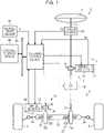
- the power supply system according to this embodiment is applied to constitute a part of a steering system 2 which is mounted in a vehicle.
- the steering system 2 is a steer-by-wire steering system.
- the steering system 2 includes a steering control device 1 that controls an operation of the steering system 2.
- the steering system 2 includes a steering unit 4 that is steered by a driver using a steering wheel 3 and a turning unit 6 that turns turning wheels 5 according to steering input to the steering unit 4 by a driver.
- the steering system 2 according to this embodiment has a structure in which a power transmission path between the steering unit 4 and the turning unit 6 is normally mechanically cut off.
- the steering unit 4 includes a steering shaft 11 to which the steering wheel 3 is fixed and a steering actuator 12 that applies a steering reaction force which is a force against the driver's steering to the steering wheel 3 via the steering shaft 11.
- the steering actuator 12 includes a steering-side motor 13 that serves as a drive source and a steering-side speed reduction mechanism 14 that reduces rotation (i.e., reduces the rotational speed) of the steering-side motor 13 and transmits the reduced rotation to the steering shaft 11.
- a three-phase brushless motor is employed as the steering-side motor 13 according to this embodiment.
- the turning unit 6 includes a first pinion shaft 21 and a rack shaft 22 that is a turning shaft connected to the first pinion shaft 21.
- the first pinion shaft 21 and the rack shaft 22 are arranged at a predetermined crossing angle.
- a first rack and pinion mechanism 23 is configured by causing first pinion teeth 21a formed in the first pinion shaft 21 and first rack teeth 22a formed in the rack shaft 22 to engage with each other.
- Tie rods 24 are respectively connected to both ends of the rack shaft 22.
- the distal ends of the tie rods 24 are respectively connected to knuckles (not illustrated) to which the right and left turning wheels 5 are assembled.
- the turning unit 6 includes a turning actuator 31 that applies a turning force for turning the turning wheels 5 to the rack shaft 22.
- the turning actuator 31 applies a turning force to the rack shaft 22 via a second pinion shaft 32.
- the turning actuator 31 includes a turning-side motor 33 that serves as a drive source and a turning-side speed reduction mechanism 34 that reduces rotation (i.e., reduces the rotational speed) of the turning-side motor 33 and transmits the reduced rotation to the second pinion shaft 32.
- the second pinion shaft 32 and the rack shaft 22 are arranged at a predetermined crossing angle.
- a second rack and pinion mechanism 35 is configured by causing second pinion teeth 32a formed in the second pinion shaft 32 and second rack teeth 22b formed in the rack shaft 22 to engage with each other.
- the second pinion shaft 32 is rotationally driven by the turning actuator 31 according to a driver's steering operation and this rotation is converted to an axial motion of the rack shaft 22 by the second rack and pinion mechanism 35, whereby the turning angle of the turning wheels 5 is changed.
- a steering reaction force against the driver's steering a force acting in a direction opposite to the driver's steering direction is applied to the steering wheel 3 from the steering actuator 12.
- the reason why the first pinion shaft 21 is provided is that the rack shaft 22 is supported together with the first pinion shaft 21 in a housing which is not illustrated. That is, by a support mechanism (not illustrated) which is provided in the steering system 2, the rack shaft 22 is supported to be movable in an axial direction thereof and is pressed toward the first pinion shaft 21 and the second pinion shaft 32. Accordingly, the rack shaft 22 is supported in the housing.
- Another support mechanism that supports the rack shaft 22 in the housing may be provided instead of using the first pinion shaft 21.
- the steering control device 1 is connected to the steering-side motor 13 and the turning-side motor 33.
- the steering control device 1 controls operations of the steering-side motor 13 and the turning-side motor 33. That is, the steering control device 1 performs control such that the steering system 2 operates to exhibit a desired function of a steer-by-wire steering system by controlling the operations of the motors 13 and 33.
- a torque sensor 41 that detects a steering torque Th applied to the steering shaft 11 is connected to the steering control device 1.
- the torque sensor 41 is provided on the steering shaft 11 at a position closer to the steering wheel 3 than a connection part connected to the steering-side speed reduction mechanism 14.
- the torque sensor 41 detects the steering torque Th based on an amount of torsion of a torsion bar which is provided at a portion of the steering shaft 11.
- a steering-side rotation angle sensor 42 and a turning-side rotation angle sensor 43 are connected to the steering control device 1.
- the steering-side rotation angle sensor 42 detects a steering-side rotation angle ⁇ a of the steering-side motor 13 as a relative angle within a range of 360 degrees.
- the turning-side rotation angle sensor 43 detects a turning-side rotation angle ⁇ b of the turning-side motor 33 as a relative angle within a range of 360 degrees.
- a vehicle speed sensor 44 is connected to the steering control device 1.
- the vehicle speed sensor 44 detects a vehicle speed value V which is set as information indicating a travel speed of a vehicle.
- An external control device 60 is connected to the steering control device 1 via an onboard network 50 such as a CAN.
- the external control device 60 is provided in the vehicle separately from the steering control device 1 and controls an operation of a system that exhibits a desired function which is different from the function exhibited by the steering system 2.
- the steering control device 1 receives information from the external control device 60 via the onboard network 50.
- the steering control device 1 includes a steering-side control unit 70 that controls supply of electric power to the steering-side motor 13 and a turning-side control unit 80 that controls supply of electric power to the turning-side motor 33.
- the steering-side control unit 70 and the turning-side control unit 80 transmit and receive information to and from each other via a local network 90 such as a serial communication network.
- the steering-side control unit 70 is provided as a part of the configuration of the steering unit 4.
- the turning-side control unit 80 is provided as a part of the configuration of the turning unit 6.
- the steering-side control unit 70 calculates a reaction control value serving as a target of a steering reaction force of the steering wheel 3 which is to be generated by the steering-side motor 13 based on detection results from various sensors.
- the steering-side control unit 70 controls supply of electric power to the steering-side motor 13 based on the reaction control value.
- the turning-side control unit 80 calculates a turning control value serving as a target of a turning force which is to be generated by the turning-side motor 33 based on the detection results from the sensors.
- the turning-side control unit 80 controls supply of electric power to the turning-side motor 33 based on the turning control value.
- the steering-side control unit 70 includes a central processing unit (CPU) and a memory which are not illustrated and the CPU executes a program stored in the memory at intervals of a predetermined calculation cycle. Accordingly, various processes are performed.
- the steering-side control unit 70 includes two systems, i.e., a main control unit 70a and a sub control unit 70b as control systems which are realized by combination of a CPU and a memory such that various processes are performed.
- the steering-side control unit 70 operates in a control scheme of a master-slave system in which the main control unit 70a is used as a master control unit and the sub control unit 70b is used as a slave control unit. The same applies to the turning-side control unit 80.
- the turning-side control unit 80 includes two systems, i.e., a main control unit 80a and a sub control unit 80b as control systems which are realized by combination of a CPU and a memory such that various processes are performed, and the control units 80a and 80b are configured to operate in a control scheme of a master-slave system.
- the control units 70a and 70b of the steering-side control unit 70 and the control units 80a and 80b of the turning-side control unit 80 are configured to communicate with each other via a local network 90.
- the control units 70a and 70b of the steering-side control unit 70 and the control units 80a and 80b of the turning-side control unit 80 are configured to communicate with an external control unit 60a of the external control device 60 via the onboard network 50.
- a main power supply 100 is connected to the steering system 2.
- the main power supply 100 is a secondary battery mounted in the vehicle, serves as a power source of electric power which is supplied to operate the motors 13 and 33, and serves as a power source of electric power which is supplied to operate the steering-side control unit 70 and the turning-side control unit 80.
- a start switch 110 of the vehicle such as an ignition switch is provided between the steering system 2 and the main power supply 100.
- the start switch 110 is provided at a portion of a power supply line L2 branching from a connection point P0 of a power supply line L1 out of two power supply lines L1 and L2 connecting the steering system 2 and the main power supply 100.
- the start switch 110 is operated when a travel drive source of the vehicle such as an engine is operated and various functions are started to operate the vehicle.
- the power supply line L2 is switched on or off through the operation of start switch 110.
- an operation status of the steering system 2 that can exhibit a desired function of a steer-by-wire steering system is correlated with an operation status of the vehicle.
- the power supply line L1 is basically normally switched on, but the power supply line L1 is indirectly switched on or off by the function of the steering system 2 according to the operation status of the steering system 2. That is, the operation status of the steering system 2 is correlated with switching-on/off of the power supply lines L1 and L2 which is a status of supply of electric power from the main power supply 100.
- the power supply lines L1 and L2, that is, the main power supply 100 is/are connected particularly to the main control unit 70a of the steering-side control unit 70 via an auxiliary power supply device 120.
- the power supply lines L1 and L2, that is, the main power supply 100 is/are directly connected particularly to the sub control unit 70b of the steering-side control unit 70 without passing through the auxiliary power supply device 120.
- the power supply lines L1 and L2, that is, the main power supply 100, is/are directly connected particularly to the sub control unit 80b of the turning-side control unit 80 without passing through the auxiliary power supply device 120. That is, in this embodiment, the single auxiliary power supply device 120 is shared by the steering-side control unit 70 and the turning-side control unit 80.
- the auxiliary power supply device 120 does not have a function of receiving information from the external control device 60 via the onboard network 50. That is, the auxiliary power supply device 120 is physically isolated from the onboard network 50 and is configured not to receive information from the external control device 60 via the onboard network 50. On the other hand, the auxiliary power supply device 120 is configured to communicate with the main control unit 70a of the steering-side control unit 70 via a dedicated signal line 140. The auxiliary power supply device 120 is configured not to communicate with the main control unit 80a of the turning-side control unit 80 via a dedicated signal line. This is because a position at which the auxiliary power supply device 120 according to this embodiment is provided is set to be between the steering unit 4 and the turning unit 6 and to be closer to the steering unit 4 in the steering system 2.
- the auxiliary power supply device 120 is prepared as an auxiliary power supply device for the steering-side control unit 70 and the turning-side control unit 80, that is, the steering system 2.
- the auxiliary power supply device 120, the steering-side control unit 70, and the turning-side control unit 80 constitute a power supply system S.
- the power supply system S is applied as a power supply system for the steering unit 4 and the turning unit 6, that is, the steering system 2.
- a configuration of the power supply system S will be described below in detail.
- a configuration associated with the steering unit 4 will be mainly described and only a configuration different from the configuration associated with the steering unit 4 will be described as the configuration associated with the turning unit 6.
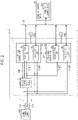
- electric power from the main power supply 100 is supplied to a power circuit 71a of the main control unit 70a via a power supply line L11 branching from a connection point P11 of the power supply line L1.
- the power circuit 71a is a circuit that handles more electric power and includes, for example, an inverter that converts DC power of the main power supply 100 to AC power.
- Electric power from the main power supply 100 is supplied to a control circuit 72a of the main control unit 70a via a power supply line L21 branching from a connection point P12 of the power supply line L2.
- the control circuit 72a is a circuit that controls the steering-side motor 13 and includes, for example, a CPU and a memory.
- Electric power from the main power supply 100 is supplied to a power circuit 71b of the sub control unit 70b via a power supply line L12 branching from the connection point P11 of the power supply line L1.
- the power circuit 71b has the same configuration as that of the power circuit 71a.
- Electric power from the main power supply 100 is supplied to a control circuit 72b of the sub control unit 70b via a power supply line L22 branching from the connection point P12 of the power supply line L2.
- the control circuit 72b has the same configuration as the control circuit 72a.
- the turning-side control unit 80 has a configuration corresponding to the steering-side control unit 70. That is, the turning-side control unit 80 has a configuration of the main control unit 80a corresponding to the power circuit 71a and the control circuit 72a. The turning-side control unit 80 has a configuration of the sub control unit 80b corresponding to the power circuit 71b and the control circuit 72b. That is, as illustrated in FIG. 3 , the turning-side control unit 80 includes a power circuit 81a and a control circuit 82a in the main control unit 80a. Similarly, the turning-side control unit 80 includes a power circuit 81b and a control circuit 82b in the sub control unit 80b.
- control circuit 82a is different from the control circuit 72a in that the control circuit 82a is configured not to output information to an auxiliary-power-supply control unit 128 (which will be described later) of the auxiliary power supply device 120 via a signal line 140.
- the auxiliary power supply device 120 includes an auxiliary power supply 121, an electrical circuit 122, switches 123, 124, and 125, diodes 126 and 127, and an auxiliary-power-supply control unit 128.
- the auxiliary power supply 121 is a capacitor such as a lithium-ion capacitor having the same function as the function of a secondary battery.
- the auxiliary power supply 121 serves as a power source of electric power which is supplied to operate the steering-side motor 13 and also serves as a power source of electric power which is supplied to operate the steering-side control unit 70.
- a voltage V2 of the auxiliary power supply 121 is set to a value which is higher than a voltage V0 required for causing the motors 13 and 33 or the control units 70 and 80 to operate appropriately and lower than a voltage V1 of the main power supply 100.
- the auxiliary power supply 121 is connected to a connection point P11 of a power supply line L11 via a power supply line L111 branching from a connection point P13 of the power supply line L11.
- the auxiliary power supply 121 is connected to the connection point P11 of the power supply line L11 via a power supply line L112 branching from a connection point P14 of the power supply line L11.
- the connection point P14 is located on the downstream side of the connection point P13, that is, the connection point P14 is located closer to the steering-side control unit 70 (the turning-side control unit 80) than the connection point P13 is.
- the auxiliary power supply 121 serves to assist supply of electric power to the steering-side control unit 70 (the turning-side control unit 80) according to a status of supply of electric power from the main power supply 100.
- the auxiliary power supply 121 backs up the supply of electric power to the steering-side control unit 70 (the turning-side control unit 80) instead of the main power supply 100 on the condition that there is a decrease in an amount of electric power supplied from the main power supply 100.
- the electrical circuit 122 switches a state of connection to the power supply line L11 such that the auxiliary power supply 121 is charged with or discharges electric power.
- the electrical circuit 122 switches the state of connection to the power supply line L11 such that the auxiliary power supply 121 is disconnected in order not to discharge electric power from the auxiliary power supply 121.
- the switch 123 is provided at a portion of the power supply line L11 in the auxiliary power supply device 120.
- the switch 123 is located on the upstream side of the connection point P13, that is, the switch 123 is located closer to the main power supply 100 than the connection point P13 is.
- the switch 123 connects and disconnects the power supply line L11.
- the switch 124 is provided at a portion of the power supply line L111 in the auxiliary power supply device 120.
- the switch 124 connects and disconnects the power supply line L111.
- the switch 125 is located at a portion of the power supply line L112 in the auxiliary power supply device 120.
- the switch 125 connects and disconnects the power supply line L112.
- connection point P15 is set in the power supply line L112.
- the connection point P15 in the power supply line L112 and a connection point P16 in the power supply line L21 are connected by a power supply line L113.
- the diode 126 is provided at a portion of the power supply line L113.
- a cathode of the diode 126 is connected to the connection point P16 in the power supply line L21.
- An anode of the diode 126 is connected to the connection point P15 in the power supply line L113.
- the diode 127 is provided at a portion of the power supply line L21.
- a cathode of the diode 127 is connected to the connection point P16 in the power supply line L21.
- An anode of the diode 127 is connected to the connection point P12 in the power supply line L21.
- Each of the diodes 126 and 127 permits a flow of electric power from the anode to the cathode and restrains a flow of electric power from the cathode to the anode.
- the diodes 126 and 127 constitute an OR circuit that supplies electric power from a power supply with a higher supply voltage out of the main power supply 100 and the auxiliary power supply 121 to the control circuit 72a.
- the diodes 126 and 127 constitute an OR circuit that supplies electric power from one of the main power supply 100 and the auxiliary power supply 121 to the control circuit 72a, the one of the main power supply 100 and the auxiliary power supply 121 having a higher supply voltage than a supply voltage of the other.
- the OR circuit constituted by the diodes 126 and 127 is a so-called wired OR.
- the OR circuit constituted by the diodes 126 and 127 corresponds to a selection circuit that selects electric power from a power supply with a higher supply voltage out of the main power supply 100 and the auxiliary power supply 121 such that the electric power is supplied to the steering-side control unit 70 (the turning-side control unit 80).
- the auxiliary-power-supply control unit 128 includes a central processing unit (CPU) and a memory which are not illustrated and the CPU executes a program stored in the memory at intervals of a predetermined calculation cycle. Accordingly, various processes are performed.
- CPU central processing unit
- memory which are not illustrated and the CPU executes a program stored in the memory at intervals of a predetermined calculation cycle. Accordingly, various processes are performed.
- the auxiliary-power-supply control unit 128 controls switching of the connection state of the electrical circuit 122 and controls switching-on/off of the switches 123, 124, and 125.
- the auxiliary-power-supply control unit 128 monitors a voltage of the main power supply 100.
- the auxiliary-power-supply control unit 128 determines that a source voltage Vb of the main power supply 100 has decreased when the source voltage Vb of the main power supply 100 is lower than a threshold voltage Vth1 as expressed by the following Expression (B).
- the threshold voltage Vth1 serves as a reference for determining a decrease in voltage of the main power supply 100 and is set based on the voltage V0 required for appropriately operating the motors 13 and 33 or the control units 70 and 80. In this embodiment, the threshold voltage Vth1 is set to the same value as the voltage V0.
- the auxiliary-power-supply control unit 128 When a decrease in voltage of the main power supply 100 has not been detected, the auxiliary-power-supply control unit 128 maintains the switches 123 and 124 in a closed state in which the switches 123 and 124 are switched on and maintains the switch 125 in an open state in which the switch 125 is switched off.
- the auxiliary-power-supply control unit 128 switches the switches 123 and 124 from the closed state in which the switches 123 and 124 are switched on to the open state in which the switches 123 and 124 are switched off. Thereafter, the auxiliary-power-supply control unit 128 switches the switch 125 from the open state in which the switch 125 is switched off to the closed state in which the switch 125 is switched on.
- the switches 123 and 124 are maintained in the closed state in which the switches 123 and 124 are switched on and the switch 125 is maintained in the open state in which the switch 125 is switched off.
- electric power from the main power supply 100 is supplied to the power circuit 71a of the steering-side control unit 70 via the power supply line L11. Electric power from the main power supply 100 is supplied and charged into the auxiliary power supply 121 via the power supply line L111.
- the switches 123 and 124 are switched from the closed state in which the switches 123 and 124 are switched on to the open state in which the switches 123 and 124 are switched off. Thereafter, the switch 125 is switched from the open state in which the switch 125 is switched off to the closed state in which the switch 125 is switched on. Accordingly, electric power from the auxiliary power supply 121 is supplied to the power circuit 71a of the steering-side control unit 70 via the power supply line L112 and a part of the power supply line L11.
- the voltage V2 of the auxiliary power supply 121 is higher than the voltage of the power supply line L11 due to the failure of the main power supply 100. Accordingly, even when supply of electric power from the main power supply 100 to the steering-side control unit 70 is stopped due to a failure of the main power supply 100, the auxiliary power supply 121 backs up the supply of electric power to the power circuit 71a of the steering-side control unit 70.
- a diode instead of the switch 125 may be provided in the power supply line L112.
- the switch 125 instead of a diode is provided in the power supply line L112 for supplying electric power to the power circuit 71a requiring higher electric power.
- a switch instead of the diode 126 may be provided in the power supply line L113.
- the control circuit 72a may be reset due to instantaneous stopping of the supply of electric power to the control circuit 72a.
- the steering-side control unit 70 and the turning-side control unit 80 correspond(s) to a system control unit.
- the diode 127 corresponds to a first diode.
- the diode 126 corresponds to a second diode.
- the power supply line L21 corresponds to a first power supply path.
- the power supply line L113 corresponds to a second power supply path.
- the auxiliary-power-supply control unit 128 corresponds to an auxiliary-power-supply control unit.
- the control circuit 72a has a function of detecting a voltage of electric power supplied via the power supply line L21 as a source voltage Vig1 of the main power supply 100.
- the source voltage Vig1 is a source voltage at the connection point P16 in the power supply line L21.
- the control circuit 72b has a function of detecting a voltage of electric power supplied via the power supply line L22 as a source voltage Vig2 of the main power supply 100.
- the source voltage Vig2 is a source voltage at the connection point P12 in the power supply line L21.
- control circuit 82a of the main control unit 80a of the turning-side control unit 80 having the same configuration as that of the steering-side control unit 70 has a function of detecting a voltage of electric power supplied via a power supply line corresponding to the power supply line L21 as a source voltage Vig3 of the main power supply 100.
- the control circuit 82b of the sub control unit 80b of the turning-side control unit 80 has a function of detecting a voltage of electric power supplied via a power supply line corresponding to the power supply line L22 as a source voltage Vig4 of the main power supply 100.
- the detected source voltages Vig1 to Vig4 are output to the control units 70a and 70b of the steering-side control unit 70 and the control units 80a and 80b of the turning-side control unit 80 via the local network 90 and are shared by the control units 70 and 80.
- the control circuit 72a of the main control unit 70a acquires the source voltages Vig2 and Vig4 which are input via the local network 90.
- the control circuit 72a of the main control unit 70a acquires a vehicle stop flag FLG1 which is input via the onboard network 50 and acquires a turning-side vehicle stop flag FLG1t which is input via the local network 90.
- the vehicle stop flag FLG1 is information which is generated by the external control unit 60a and output to the onboard network 50 and which indicates an operation status of the vehicle. That is, the vehicle stop flag FLG1 is information indicating that the operation of the vehicle is stopped, that is, that the start switch 110 is turned off and the supply of electric power from the main power supply 100 is stopped.
- the external control unit 60a is configured to generate the vehicle stop flag FLG1 as a determination result indicating that the operation of the vehicle is stopped by detecting turning-on/off of the start switch 110 or detecting a vehicle speed value V from the vehicle speed sensor 44.
- the turning-side vehicle stop flag FLG1t is information which is generated based on the vehicle stop flag FLG1 acquired via the onboard network 50 by the control circuit 82a of the main control unit 80a of the turning-side control unit 80 and is information which is acquired from the control circuit 82a via the local network 90 by the control circuit 72a. That is, the control circuit 82a of the turning-side control unit 80 acquires the vehicle stop flag FLG1 which is input via the onboard network 50 similarly to the control circuit 72a.
- the vehicle stop flag FLG1 acquired in this way by the control circuit 82a is output as the turning-side vehicle stop flag FLG1t to the main control unit 70a of the steering-side control unit 70 via the local network 90.
- the control circuit 72a determines that the start switch 110 is turned off and the supply of electric power is stopped as the status of supply of electric power from the main power supply 100. That is, the control circuit 72a determines that all of the source voltage Vig2 detected by the steering-side control unit 70 and the source voltage Vig4 acquired by the turning-side control unit 80 are lower than the threshold voltage Vth2.
- the threshold voltage Vth2 is a value in a range in which it can be determined that the supply of electric power from the main power supply 100 is stopped, the range being experimentally obtained.
- the threshold voltage Vth2 is set based on the value of the source voltage Vig2 when the supply of electric power from the main power supply 100 is stopped or the source voltage Vig4 assumed to indicate substantially the same value as the source voltage Vig2.
- the conditions regarding the source voltages Vig2 and Vig4 are added and the conditions regarding the source voltages Vig1 and Vig3 are not added when it is determined whether the start switch 110 is turned off and the supply of electric power from the main power supply 100 is stopped. This is because the source voltages Vig2 and Vig4 change to decrease to the threshold voltage Vth2 when the start switch 110 is turned off and the source voltages Vig1 and Vig3 may not decrease to the threshold voltage Vth2 when the start switch 110 is turned off.
- the reason why the source voltage Vig1 and Vig3 do not decrease to the threshold voltage Vth2 when the start switch 110 is turned off is that supply of electric power may be maintained similarly to the case in which the start switch 110 is turned on by the functions of the auxiliary power supply 121 and the diodes 126 and 127 even when the start switch 110 is turned off.
- the control circuit 72a may be configured to compare one source voltage of the source voltage Vig2 and the source voltage Vig4 with the threshold voltage Vth2.
- the source voltage Vig1 as well as the source voltage Vig2 is detected to decrease together when it is determined whether the supply of electric power from the main power supply 100 is stopped, it can be estimated that an abnormality of a power supply such as disconnection of the power supply line L21 or L22 has occurred, instead of turning-off of the start switch 110.
- an absolute value of a difference between the source voltage Vig1 and the source voltage Vig2 is information indicating an amount by which the source voltage Vig2 changes to decrease when the start switch 110 is turned off.
- the control circuit 72a When it is determined that the supply of electric power from the main power supply 100 is stopped, the control circuit 72a performs a process associated with the stopping such that the operation of the steering-side control unit 70 stops. In this case, when the operation of the steering-side control unit 70 is stopped, the control circuit 72a performs the process required for stopping the operation of the steering-side control unit 70, generates a stop permission flag FLG2 as information indicating that the operation is stopped for the auxiliary-power-supply control unit 128, and outputs the stop permission flag FLG2 to the auxiliary-power-supply control unit 128 via the signal line 140.
- the steering-side control unit 70 may not perform any process or may perform a process as long as it is a process which is not affected by sudden stopping of supply of electric power from the main power supply 100 and the auxiliary power supply 121.
- the turning-side control unit 80 determines whether the supply of electric power from the main power supply 100 is stopped through the process in the control circuit 82a based on the source voltages Vig2 and Vig4 and the vehicle stop flag FLG1.
- the turning-side control unit 80 performs a process associated with the stopping such that the operation of the turning-side control unit 80 is stopped, and outputs the turning-side vehicle stop flag FLG1t generated based on the vehicle stop flag FLG1 to the steering-side control unit 70 via the local network 90. That is, the turning-side vehicle stop flag FLG1t is information indicating that the operation of the turning-side control unit 80 is stopped.
- the stop permission flag FLG2 which is generated in consideration of the turning-side vehicle stop flag FLG1t is also information indicating that the operation of the turning-side control unit 80 is stopped.
- the turning-side control unit 80 may not perform any process or may perform a process as long as it is a process which is not affected by sudden stopping of supply of electric power from the main power supply 100 and the auxiliary power supply 121.
- the control circuit 72a After the control circuit 72a has output the stop permission flag FLG2, the function of backing up the supply of electric power from the main power supply 100 using the auxiliary power supply 121 is actually stopped and thus the supply of electric power from the main power supply 100 and the auxiliary power supply 121 to the steering-side control unit 70 is stopped. That is, there is a slight time difference between the timing at which the stop permission flag FLG2 is output and the timing at which the supply of electric power from the main power supply 100 and the auxiliary power supply 121 to the steering-side control unit 70 is stopped.
- This slight time difference includes a time period until the stop permission flag FLG2 is input to the auxiliary-power-supply control unit 128 after the stop permission flag FLG2 has been output or a time period until the auxiliary-power-supply control unit 128 actually stops the operation thereof after the stop permission flag FLG2 has been input.
- the control circuit 72a does not determine whether the supply of electric power from the main power supply 100 is stopped and does not generate and output the stop permission flag FLG2.
- the auxiliary-power-supply control unit 128 performs a process associated with the stopping such that the operation of the steering-side control unit 70 is stopped.
- the auxiliary-power-supply control unit 128 switches the connection state of the electrical circuit 122 such that electric power from the auxiliary power supply 121 is not supplied. That is, the auxiliary power supply device 120 stops supply of electric power to the steering-side control unit 70 by stopping the function of backing up the supply of electric power from the main power supply 100 using the auxiliary power supply 121. In this case, the auxiliary power supply device 120 stops the function of backing up the supply of electric power from the main power supply 100 using the auxiliary power supply 121 regardless of the amount of residual electric power in the auxiliary power supply 121.
- the supply of electric power from the main power supply 100 is stopped, the supply of electric power from the auxiliary power supply 121 is avoided by switching the connection state of the electrical circuit 122 and thus the supply of electric power to the steering-side control unit 70 is stopped.
- the steering-side control unit 70 does not continue to operate and stops the operation thereof.
- the turning-side control unit 80 that is, when the supply of electric power from the main power supply 100 is stopped, the supply of electric power from the auxiliary power supply 121 is avoided by switching the connection state of the electrical circuit 122 and thus the supply of electric power to the turning-side control unit 80 is stopped. In this case, since the supply of electric power from the main power supply 100 is stopped, the turning-side control unit 80 does not continue to operate and stops the operation thereof.
- the situation in which a decrease of the voltage of the main power supply 100 is detected includes a situation in which the start switch 110 is turned off and a situation in which the start switch 110 is turned on, the main power supply 100 fails to operate, and supply of electric power from the main power supply 100 to the steering-side control unit 70 is cut off.
- the source voltage Vig2 and Vig4 are lower than the threshold voltage Vth2, and the vehicle stop flag FLG1, the turning-side vehicle stop flag FLG1t, and the stop permission flag FLG2 are not generated and are not output.
- the auxiliary-power-supply control unit 128 outputs information indicating that fact to the steering-side control unit 70 via the signal line 140.
- the steering-side control unit 70 performs control based on the situation in which the main power supply 100 fails to operate.
- Information indicating the situation in which the main power supply 100 fails to operate is input to the turning-side control unit 80 from the steering-side control unit 70 via the local network 90.
- the turning-side control unit 80 performs control based on the situation in which the main power supply 100 fails to operate.
- the auxiliary-power-supply control unit 128 can receive the stop permission flag FLG2 as information indicating that the operations are stopped from the steering-side control unit 70.
- the auxiliary-power-supply control unit 128 determines whether to stop the operation thereof, the auxiliary-power-supply control unit 128 can determine whether the operation thereof is to be stopped in consideration of whether the control units 70 and 80 stop their operations.
- a portion (a) in FIG. 4 illustrates that the turning-on/off state of the start switch 110, that is, a state of supply of electric power from the main power supply 100 changes with the elapse of time t.
- electric power from the main power supply 100 is basically supplied to the steering system 2, that is, the steering-side control unit 70 and the turning-side control unit 80.
- the statuses of detecting of the source voltages Vig2 and Vig4 indicate the state in which the start switch 110 is turned on. That is, the source voltages Vig2 and Vig4 are in a status in which the source voltages Vig2 and Vig4 are detected to be equal to or greater than the threshold voltage Vth2, the status being indicated by "1" in the drawing.
- the vehicle stop flag FLG1 is in a status in which it is not output from the external control unit 60a, the status being indicated by "0 (zero)” in the drawing.
- the turning-side vehicle stop flag FLG1t is in a status in which it is not output from the control circuit 82a of the turning-side control unit 80, the status being indicated by "0 (zero)” in the drawing.
- the stop permission flag FLG2 is in a status in which it is not output from the control circuit 72a of the main control unit 70a, the status being indicated by "0 (zero)” in the drawing.
- the auxiliary-power-supply control unit 128 is in a status in which it operates to perform back-up using the auxiliary power supply 121 when the amount of electric power supplied from the main power supply 100 decreases, the status being indicated by "ON” in the drawing.
- the supply of electric power to the control units 70 and 80 is in a status in which electric power is supplied to the control units 70 and 80 from the main power supply 100 or the auxiliary power supply 121 such that the control units 70 and 80 continue to operate, the status being indicated by "ON" in the drawing.
- the start switch 110 is switched off as illustrated in the portion (a) in FIG. 4 , the supply of electric power from the main power supply 100 to the control units 70 and 80 is stopped.
- the statuses of detecting of the source voltages Vig2 and Vig4 outputting of the vehicle stop flag FLG1, outputting of the turning-side vehicle stop flag FLG1t, outputting of the stop permission flag FLG2, operating of the auxiliary-power-supply control unit 128, and supply of electric power to the control units 70 and 80 in the power supply system S indicate the state in which the start switch 110 is turned off.
- the source voltages Vig2 and Vig4 transition to a status in which the source voltages are detected to be less than the threshold voltage Vth2, the status being indicated by "0 (zero)" in the drawing.
- the vehicle stop flag FLG1 transitions to a status in which it is output from the external control unit 60a, the status being indicated by “1” in the drawing.
- the turning-side vehicle stop flag FLG1t transitions to a status in which it is output from the control circuit 82a of the turning-side control unit 80, the status being indicated by "1" in the drawing.
- the stop permission flag FLG2 transitions to a status in which it is output from the control circuit 72a, the status being indicated by "1" in the drawing.
- the auxiliary-power-supply control unit 128 transitions to a status in which the function of backing up the supply of electric power from the main power supply 100 using the auxiliary power supply 121 is stopped on the condition that the stop permission flag FLG2 is acquired, the status being indicated by "OFF" in the drawing.
- the supply of electric power to the control units 70 and 80 transitions to a status in which the supply of electric power is stopped such that the control units 70 and 80 do not continue to operate using electric power supplied from the main power supply 100 or the auxiliary power supply 121, the status being indicated by "OFF" in the drawing.
- the auxiliary-power-supply control unit 128 does not continue to operate and can stop the operation thereof in the situation in which the steering-side control unit 70 stops the operation thereof, and the auxiliary-power-supply control unit 128 does not stop the operation thereof and can continue to operate in the situation in which the steering-side control unit 70 continues to operate.
- the turning-side control unit 80 does not stop the operation thereof and can continue to operate in the situation in which the steering-side control unit 70 continues to operate.
- the auxiliary-power-supply control unit 128 does not continue to operate and can stop the operation thereof in the situation in which the turning-side control unit 80 stops the operation thereof, and the auxiliary-power-supply control unit 128 does not stop the operation thereof and can continue to operate in the situation in which the turning-side control unit 80 continues to operate.
- (1-1) For example, when the configuration for generating and outputting the stop permission flag FLG2 is not provided, there is a likelihood that the auxiliary-power-supply control unit 128 will not able to determine that the control units 70 and 80 are to stop their operations even when the control units 70 and 80 are to stop their operations in a state in which the supply of electric power from the main power supply 100 is stopped.
- the auxiliary-power-supply control unit 128 tries to continuously operate even in the state in which the supply of electric power from the main power supply 100 is stopped, the auxiliary power supply 121 backs up supply of electric power to the control circuits 72a and 82a instead of the main power supply 100.
- control units 70 and 80 are continuously supplied with electric power from the auxiliary power supply 121, the control units 70 and 80 fall into an unexpected situation in which they continue to operate even when their operations are to be stopped in the state in which the supply of electric power from the main power supply 100 is stopped. As in this embodiment, this causes a problem particularly when the function of a diode OR that selects electric power from the power supply with a higher supply voltage out of the main power supply 100 and the auxiliary power supply 121 is provided.
- control units 70 and 80 and the auxiliary-power-supply control unit 128 it is possible to set a rule for the control units 70 and 80 and the auxiliary-power-supply control unit 128 to prevent a situation where the control units 70 and 80 or the auxiliary-power-supply control unit 128 continue(s) to operate when the control units 70 and 80 or the auxiliary-power-supply control unit 128 should stop the operation thereof in the relation with the operation status of the other control unit(s), or the control units 70 and 80 or the auxiliary-power-supply control unit 128 stop(s) the operation thereof when the control units 70 and 80 or the auxiliary-power-supply control unit 128 should not stop the operation thereof in the relation with the operation status of the other control unit (s).
- the control units 70 and 80 and the auxiliary-power-supply control unit 128 fall into an unexpected situation.
- a rule is set such that the control units 70 and 80 stop their operations when the control units 70 and 80 and the auxiliary-power-supply control unit 128 should stop the operations in consideration of the status of supply of electric power from the main power supply 100, that is, the vehicle stop flag FLG1 which is information indicating the operation status of the vehicle.
- This configuration is effective for allowing the control units 70 and 80 to perform appropriate control based on the operation status of the vehicle.
- This configuration is effective for reducing the possibility that the control units 70 and 80 and the auxiliary-power-supply control unit 128 fall into an unexpected situation.
- the steering-side control unit 70 determines the operation status of the vehicle using a plurality of pieces of information from different information sources such as the vehicle stop flag FLG1 received from the external control unit 60a, in addition to the source voltages Vig2 and Vig4. In this case, it is possible to improve accuracy of determination as to the operation status of the vehicle.
- diagnosis information is generated and stored.
- the diagnosis information is used for identifying a kind of an abnormality or the like detected as the diagnosis result, at the time of later maintenance.
- Examples of the kind of an abnormality detected as the diagnosis result include a communication abnormality in which communication between the steering-side control unit 70 and the auxiliary-power-supply control unit 128 via the signal line 140 is not normally performed.
- Examples of a situation in which the communication abnormality should be detected includes a situation in which the auxiliary-power-supply control unit 128 stops the operation thereof when communication between the steering-side control unit 70 and the auxiliary-power-supply control unit 128 via the signal line 140 is being performed and the steering-side control unit 70 is operating continuously.
- the steering-side control unit 70 and the auxiliary-power-supply control unit 128 stop their operations without determining mutual situations in the state in which supply of electric power from the main power supply 100 is stopped. Accordingly, there is a likelihood that a communication abnormality may be detected as the diagnosis result even when the communication abnormality should not be detected. In this case, an abnormality cannot be correctly identified at the time of later maintenance and a decrease in work efficiency of maintenance work or the like may be caused.
- the second embodiment is different from the first embodiment, in that auxiliary power supply devices 120 are individually provided to correspond to the control units 70 and 80 and the single auxiliary power supply device 120 is not shared by the control units 70 and 80.
- a steering-side auxiliary power supply device 120S is provided as an auxiliary power supply device for the steering-side control unit 70.
- the steering-side auxiliary power supply device 120S and the steering-side control unit 70 constitute a power supply system SS.
- the power supply system SS is applied as a power supply system for the steering unit 4 in the steering system 2.
- a turning-side auxiliary power supply device 120T is provided as an auxiliary power supply device for the turning-side control unit 80.
- the turning-side auxiliary power supply device 120T and the turning-side control unit 80 constitute a power supply system ST.
- the power supply system ST is applied as a power supply system for the turning unit 6 in the steering system 2.
- the specific configuration of the steering-side control unit 70 is the same as a configuration in which the steering-side auxiliary power supply device 120S is replaced with the auxiliary power supply device 120 according to the first embodiment.
- the power supply lines L1 and L2, that is, the main power supply 100 are/is connected to the main control unit 70a of the steering-side control unit 70 via the auxiliary power supply device 120S.
- the power supply lines L1 and L2, that is, the main power supply 100 are/is directly connected to the sub control unit 70b of the steering-side control unit 70 without passing through the auxiliary power supply device 120S.
- the auxiliary power supply device 120S is configured to communicate with the main control unit 70a of the steering-side control unit 70 via a dedicated signal line 140S.
- the specific configuration of the turning-side control unit 80 is the same as a configuration in which the auxiliary power supply device 120T is replaced with the auxiliary power supply device 120 according to the first embodiment and the turning-side control unit 80 is replaced with the steering-side control unit 70 according to the first embodiment.
- the power supply lines L1 and L2, that is, the main power supply 100 are/is connected to the main control unit 80a of the turning-side control unit 80 via the auxiliary power supply device 120T.
- the power supply lines L1 and L2, that is, the main power supply 100 are/is directly connected to the sub control unit 70b of the turning-side control unit 80 without passing through the auxiliary power supply device 120T.
- the auxiliary power supply device 120T is configured to communicate with the main control unit 80a of the turning-side control unit 80 via a dedicated signal line 140T.
- the control circuit 72a of the steering-side control unit 70 determines that the start switch 110 is turned off and the supply of electric power from the main power supply 100 is stopped, and generates and outputs the stop permission flag FLG2. Accordingly, the auxiliary power supply device 120S stops supply of electric power to the steering-side control unit 70 by stopping the function of backing up supply of electric power from the main power supply 100 using the auxiliary power supply 121.
- the control circuit 82a of the turning-side control unit 80 determines that the start switch 110 is turned off and the supply of electric power from the main power supply 100 is stopped, and generates and outputs the stop permission flag FLG2. Accordingly, the auxiliary power supply device 120T stops supply of electric power to the turning-side control unit 80 by stopping the function of backing up supply of electric power from the main power supply 100 using the auxiliary power supply 121.
- the diodes 126 and 127 may constitute an OR circuit in the steering-side control unit 70, that is, the steering control device 1. With this configuration, electric power from the power supply with a higher supply voltage out of the main power supply 100 and the auxiliary power supply 121 is supplied to the steering-side control unit 70. The same applies to the auxiliary power supply devices 120S and 120T of the second embodiment.
- an electric double layer capacitor or a secondary battery instead of the lithium-ion capacitor may be employed in the auxiliary power supply 121.
- the voltage V2 of the auxiliary power supply 121 may be set to the same value as the voltage V1 of the main power supply 100 or may be set to be higher than the voltage V1 of the main power supply 100. The same applies to the voltage V2 of the auxiliary power supplies of the auxiliary power supply devices 120S and 120T according to the second embodiment.
- the auxiliary power supply device 120 may operate to perform assistance (i.e., provide assistance) by backing up supply of electric power to the control units 70 and 80 instead of the main power supply 100 and to perform assistance by stepping up electric power supplied from the main power supply 100.
- assistance i.e., provide assistance
- a configuration corresponding to the selection circuit such as the OR circuit constituted by the diodes 126 and 127 may be removed from the auxiliary power supply device 120.
- the auxiliary power supply devices 120S and 120T according to the second embodiment.
- the steering-side control unit 70 may determine whether the start switch 110 is turned on or off using a source voltage Vb instead of the source voltages Vig2 and Vig4. The same applies to the control units 70 and 80 according to the second embodiment.
- a function of generating information corresponding to the vehicle stop flag FLG1 as a determination result indicating that the operation of the vehicle is stopped by detecting turning-on/off of the start switch 110 or detecting the vehicle speed value V from the vehicle speed sensor 44 may be added to the control units 70 and 80.
- the steering-side control unit 70 may use at least one of i) the vehicle stop flag FLG1, ii) the turning-side vehicle stop flag FLG1t, and iii) the source voltages Vig2 and Vig4 at the time of determining that the start switch 110 is turned off and the supply of electric power is stopped as a status of supply of electric power from the main power supply 100.
- the control units 70 and 80 according to the second embodiment may use at least one of i) the vehicle stop flag FLG1, ii) the turning-side vehicle stop flag FLG1t, and iii) the source voltages Vig2 and Vig4 at the time of determining that the start switch 110 is turned off and the supply of electric power is stopped as a status of supply of electric power from the main power supply 100.
- the steering-side control unit 70 may not consider the turning-side vehicle stop flag FLG1t at the time of generating the stop permission flag FLG2. For example, the steering-side control unit 70 can output the acquired turning-side vehicle stop flag FLG1t to the auxiliary-power-supply control unit 128 without any change. In this case, the auxiliary-power-supply control unit 128 can perform a process associated with the stopping such that the steering-side control unit 70 stops the operation thereof on the condition that both the stop permission flag FLG2 and the vehicle stop flag FLG1t are acquired.
- the steering-side control unit 70 may output the acquired vehicle stop flag FLG1 to the auxiliary-power-supply control unit 128 via the signal line 140.
- the output vehicle stop flag FLG1 is shared by the steering-side control unit 70 and the auxiliary-power-supply control unit 128.
- the auxiliary-power-supply control unit 128 may be configured to acquire the vehicle stop flag FLG1 via the onboard network 50 and to output the acquired vehicle stop flag FLG1 to the steering-side control unit 70 via the signal line 140.
- the steering-side control unit 70 can be configured to output the acquired vehicle stop flag FLG1 to the turning-side control unit 80 via the local network 90.
- the auxiliary-power-supply control unit 128 may be connected to be able to communicate via the onboard network 50.
- a function of determining that the operation of the vehicle is stopped that is, the start switch 110 is turned off and supply of electric power from the main power supply 100 is stopped may be added to the auxiliary-power-supply control unit 128.
- the auxiliary-power-supply control unit 128 may generate information corresponding to the stop permission flag FLG2 indicating that the operation is stopped and output the information to the steering-side control unit 70 via the signal line 140.
- the steering-side control unit 70 can be configured to output the acquired information corresponding to the stop permission flag FLG2 to the turning-side control unit 80 via the local network 90.
- the auxiliary-power-supply control unit 128 is configured to stop the operation or to receive the stop permission flag FLG2 or the like from the control units 70 and 80, when a predetermined period of time set as a period of time in a range in which the control units 70 and 80 can perform an operation stopping process has elapsed after the information corresponding to the stop permission flag FLG2 has been output.
- the control units 70 and 80 or the auxiliary-power-supply control units of the auxiliary power supply devices 120S and 120T according to the second embodiment.
- the auxiliary-power-supply control unit 128 may be configured to communicate with the main control unit 80a of the turning-side control unit 80 via the signal line 140. That is, the main control unit 80a of the turning-side control unit 80 may be configured to generate information corresponding to the stop permission flag FLG2 in the first embodiment and to directly output the information to the auxiliary-power-supply control unit 128. In this case, the auxiliary-power-supply control unit 128 may be configured not to communicate with the main control unit 70a of the steering-side control unit 70 via the signal line 140. That is, the main control unit 70a of the steering-side control unit 70 may be configured to generate information corresponding to the turning-side vehicle stop flag FLG1t in the first embodiment and to output the information to the main control unit 80a of the turning-side control unit 80.
- the processing function of determining that supply of electric power from the main power supply 100 is stopped or generating and outputting the stop permission flag FLG2 is not limited to the function of the steering-side control unit 70, that is, the control circuit 72a of the main control unit 70a, and can be appropriately modified as long as the function is realized as a function of the steering control device 1.
- the processing function may be provided, for example, as functions of both the main control unit 70a and the sub control unit 70b of the steering-side control unit 70 or may be provided as a function of only the sub control unit 70b. The same applies to the main control unit 80a and the sub control unit 80b of the turning-side control unit 80.
- the processing function can be provided as the function of the main control unit 70a of the steering-side control unit 70 or the functions of both the main control unit 70a and the sub control unit 70b, and also can be provided as the function of the main control unit 80a of the turning-side control unit 80 or the functions of both the main control unit 80a and the sub control unit 80b.
- the control units 70 and 80 may employ a technique of performing the determination or the generation of the stop permission flag FLG2 as the processing function and sharing and mediating the results of execution via the local network 90. This technique may be realized among the control units 70a, 70b, 80a, and 80b.
- the processing function may be provided as functions of both the main control units 70a and 80a and the sub control units 70b and 80b in the control units 70 and 80 or may be provided as a function of only the sub control units 70b and 80b.
- control units 70 and 80 may have a function of detecting only a required source voltage. That is, the steering-side control unit 70 may not have a function of detecting the source voltage Vig1 and may have a function of detecting only the source voltage Vig2. The turning-side control unit 80 may not have a function of detecting the source voltage Vig3 and may have a function of detecting only the source voltage Vig4. The same applies to the second embodiment.
- the main control units 70a and 80a may have the functions of detecting the source voltages Vig2 and Vig4. The same applies to the second embodiment.
- the sub control units 70b and 80b may be eliminated and only one system, i.e., the main control units 70a and 80a may be provided.
- the main control units 70a and 80a in the one system may have a function of detecting only a required source voltage.
- the second embodiment the same applies to the second embodiment.
- a function of switching off the power supply line L21 at the timing at which the stop permission flag FLG2 is output may be added to the steering-side control unit 70.
- a switch which can be switched by the control circuit 72a or the like may be provided between the connection point P16 of the power supply line L21 and the control circuit 72a. The same applies to the control units 70 and 80 according to the second embodiment.
- a single control unit having a function into which the steering-side control unit 70's function to operate the steering-side motor 13 and the turning-side control unit 80's function to operate the turning-side motor 33 are incorporated may be provided.
- the turning-side motor 33 may be connected to the rack shaft 22 via a belt type speed reducer using a ball screw mechanism or may be coaxially connected to the rack shaft 22.
- the steering control device 1 including the control units 70 and 80 may be configured as a processing circuit including (1) one or more processors that operate in accordance with a computer program (software), (2) one or more dedicated hardware circuits such as an application-specific integrated circuit (ASIC) that perform at least some of various processes, or (3) a combination thereof.
- the processor includes a CPU and memories such as a RAM and a ROM, and the memories store program codes or commands configured to cause the CPU to perform processing.
- Memories that is, non-transitory computer-readable media, include all available media that can be accessed by a general-purpose or dedicated computer. The same applies to the auxiliary-power-supply control unit 128 or the auxiliary power supply device 120 including it.
- the steering system 2 employs a linkless structure in which the steering unit 4 and the turning unit 6 are normally mechanically disconnected from each other, but the invention is not limited thereto and the steering system may employ a structure in which the steering unit 4 and the turning unit 6 can be mechanically disconnected by a clutch 25 as indicated by an alternate long and two short dashes line in FIG. 1 .
- the steering system 2 is not limited to a steer-by-wire steering system, and may be an electric power steering system in which a torque of a motor is applied to the steering shaft 11 or the rack shaft 22.
- the aforementioned embodiments are not limited to realization as a function of the steering control device 1 and may be implemented, for example, as a control device for an airbag system, a control device for a brake system, or a control device for a motor serving as a travel drive source in an unmanned transport vehicle or an electric vehicle.
- the embodiments may be implemented as a control device for a system which is mounted in an object other than a vehicle.
Landscapes
- Engineering & Computer Science (AREA)
- Mechanical Engineering (AREA)
- Chemical & Material Sciences (AREA)
- Combustion & Propulsion (AREA)
- Transportation (AREA)
- Business, Economics & Management (AREA)
- Emergency Management (AREA)
- Power Engineering (AREA)
- Power Steering Mechanism (AREA)
- Steering Control In Accordance With Driving Conditions (AREA)
- Charge And Discharge Circuits For Batteries Or The Like (AREA)
- Direct Current Feeding And Distribution (AREA)
Abstract
Description
- The invention relates to a power supply system.
- For example, a system control unit configured to control an operation of an electric power steering system (hereinafter referred to as EPS) for a vehicle performs assist control using electric power supplied from a main power supply mounted in the vehicle. The EPS is a system that performs a desired function. Supply of electric power to the system control unit from the main power supply may be assisted using a function of an auxiliary power supply which is provided separately from the main power supply.
-
Japanese Unexamined Patent Application Publication No. 2019-140883 JP 2019-140883 A - Supply of electric power from the main power supply is switched between permission and stopping, and a status of an operation of the system control unit using the electric power supplied from the main power supply is set in correlation with a status of the supply of electric power from the main power supply. Similarly, a status of an operation of the auxiliary-power-supply control unit that controls an operation of the auxiliary power supply for assisting the supply of electric power from the main power supply is set in correlation with the status of the supply of electric power from the main power supply. There is demand for taking measures regarding the system control unit and the auxiliary-power-supply control unit such that the control units do not fall into an unexpected situation such as a situation in which one of the control units operates continuously when the one control unit should stop in a relation with the other control unit, or a situation in which one of the control units stops the operation thereof when the one control unit should not stop in the relation with the other control unit.
- An aspect of the invention relates to a power supply system including a system control unit configured to operate using electric power supplied from a main power supply, so as to control an operation of a system that performs a desired function; an auxiliary power supply provided separately from the main power supply and configured to provide assistance in supply of the electric power to the system control unit according to a status of supply of the electric power from the main power supply; and an auxiliary-power-supply control unit configured to control a status of supply of the electric power to the system control unit from the auxiliary power supply such that the assistance is provided. The system control unit and the auxiliary-power-supply control unit are configured such that information of at least one control unit of the system control unit and the auxiliary-power-supply control unit is able to be output to another control unit of the system control unit and the auxiliary-power-supply control unit. The at least one control unit is configured to output information indicating that an operation of the at least one control unit is stopped to the other control unit when the at least one control unit stops the operation of the at least one control unit.
- With this configuration, when one control unit of the system control unit and the auxiliary-power-supply control unit stops the operation thereof, the other control unit can receive information indicating that the operation of the one control unit is stopped, from the one control unit. In this case, the other control unit can determine whether the operation of the other control unit is to be stopped by considering whether the one control unit stops the operation thereof or continues the operation thereof when the other control unit is to stop the operation thereof. Accordingly, it is possible to set a rule regarding the system control unit and the auxiliary-power-supply control unit to prevent a situation where one control unit continues to operate when the one control unit should stop the operation thereof in a relation with the operation status of the other control unit, or one control unit stops the operation thereof when the one control unit should not stop the operation thereof in the relation with the operation status of the other control unit. As a result, it is possible to reduce the possibility that the system control unit and the auxiliary-power-supply control unit fall into an unexpected situation.
- In the power supply system according to the aspect, the status of the supply of the electric power from the main power supply and an operation status of a mounting destination of the system may be correlated with each other; and the at least one control unit may be configured to determine whether the operation of the at least one control unit is to be stopped based on the operation status of the mounting destination of the system, and to output information indicating that the operation of the at least one control unit is stopped to the other control unit when the at least one control unit determines that the operation of the at least one control unit is stopped.
- With this configuration, it is possible to set a rule such that each of the system control unit and the auxiliary-power-supply control unit stops the operation thereof when it should stop the operation in consideration of the status of the supply of the electric power from the main power supply, that is, the operation status of the mounting destination of the system. This configuration is effective for allowing the system control unit to perform appropriate control based on the operation status of the mounting destination of the system.
- In the power supply system according to the aspect, in a case where one control unit of the system control unit and the auxiliary-power-supply control unit is a first control unit, and another control unit of the system control unit and the auxiliary-power-supply control unit is a second control unit, the first control unit may be configured to receive information indicating an operation status of a mounting destination of the system from an external control unit that is provided in the mounting destination of the system separately from the system control unit and the auxiliary-power-supply control unit such that the operation status of the mounting destination of the system is able to be determined; the first control unit may be configured to output information indicating that the first control unit stops an operation of the first control unit to the second control unit when determining that an operation of the mounting destination of the system is stopped, on a condition that stopping of the operation of the mounting destination of the system is determined using the information indicating the operation status of the mounting destination of the system when the first control unit stops the operation of the first control unit; and the second control unit may be configured to determine whether an operation of the second control unit is to be stopped using the information indicating that the first control unit stops the operation of the first control unit, the information being input from the first control unit.
- With this configuration, it is possible to set a rule such that each of the system control unit and the auxiliary-power-supply control unit stops the operation thereof when it should stop the operation thereof using the first control unit that can receive information indicating the operation status of the mounting destination of the system from the external control unit as a main control unit (master control unit). This configuration is effective for reducing the possibility that the system control unit and the auxiliary-power-supply control unit fall into an unexpected situation.
- In the power supply system according to the aspect, the system control unit and the auxiliary-power-supply control unit may be configured to determine an operation status of a mounting destination of the system using a source voltage as information indicating the status of the supply of the electric power from the main power supply.
- With this configuration, the system control unit and the auxiliary-power-supply control unit can determine the operation status of the mounting destination of the system, for example, even when information indicating the operation status of the mounting destination of the system cannot be received from an external control unit or when information indicating the operation status of the mounting destination of the system from the external control unit cannot be used. In addition to the information indicating the status of the supply of the electric power from the main power supply, a plurality of pieces of information from different information sources such as information indicating the operation status of the mounting destination of the system from the external control unit may be used to determine the operation status of the mounting destination of the system. In this case, it is possible to improve accuracy of determination as to the operation status of the mounting destination of the system.
- In the power supply system according to the aspect, the auxiliary power supply may provide the assistance in the supply of the electric power by backing up the supply of the electric power to the system control unit instead of the main power supply on a condition that there is a decrease in the electric power supplied from the main power supply; the power supply system may further include a selection circuit provided between the main power supply and the auxiliary power supply, and the system control unit, the selection circuit being configured to select the electric power from one of the main power supply and the auxiliary power supply such that the electric power is supplied to the system control unit, the one of the main power supply and the auxiliary power supply having a higher supply voltage than a supply voltage of another of the main power supply and the auxiliary power supply; and the auxiliary-power-supply control unit may be configured to control the auxiliary power supply such that the electric power from at least the auxiliary power supply is supplied to the system control unit via the selection circuit while the main power supply supplies the electric power to the system control unit.
- With this configuration, electric power of a power supply with a higher supply voltage out of the main power supply and the auxiliary power supply is selected through the function of the selection circuit. In this case, for example, by considering that the auxiliary power supply backs up the supply of the electric power when there is a decrease in the electric power supplied from the main power supply, it is conceivable that the auxiliary power supply may back up the supply of the electric power to the system control unit instead of the main power supply even in a state in which the supply of the electric power from the main power supply is stopped. This situation can be addressed by setting a rule such that the auxiliary-power-supply control unit can stop the operation thereof when the system control unit stops the operation thereof. In this way, in the case where the auxiliary power supply backs up the supply of the electric power when there is a decrease in the electric power supplied from the main power supply, it is possible to reduce the possibility that the system control unit and the auxiliary-power-supply control unit fall into an unexpected situation.
- The selection circuit may include a first diode that is provided in a first power supply path which is a path for supplying the electric power from the main power supply to the system control unit; and a second diode that is connected to a portion of the first diode provided in the first power supply path, the portion of the first diode being located on a side of the system control unit, and the second diode being provided in a second power supply path which is a path for supplying the electric power from the auxiliary power supply to the system control unit.
- In the power supply system according to the aspect, the system may be a steering system that is mounted in a vehicle and functions to operate at least one of a steering wheel and a turning wheel which are provided in the vehicle; and the system control unit may be configured to control an operation of the steering system.
- With the steering system employing the power supply system with this configuration, it is possible to reduce the possibility that the system control unit and the auxiliary-power-supply control unit fall into an unexpected situation. In this case, it is possible to effectively achieve improvement in marketability of the steering system.
- With the power supply system according to the aspect of the invention, it is possible to reduce the possibility that the system control unit and the auxiliary-power-supply control unit fall into an unexpected situation.
- Features, advantages, and technical and industrial significance of exemplary embodiments of the invention will be described below with reference to the accompanying drawings, in which like signs denote like elements, and wherein:
-
FIG. 1 is a diagram schematically illustrating a configuration of a steering system according to a first embodiment; -
FIG. 2 is a block diagram of a power supply system according to the first embodiment; -
FIG. 3 is a block diagram of a power supply system of a steering unit according to the first embodiment; - A portion (a) in
FIG. 4 is a diagram illustrating a turning-on/off state of a start switch, a portion (b) inFIG. 4 is a diagram illustrating detection states of source voltages, portions (c) and (d) inFIG. 4 are diagrams illustrating an output state of a vehicle stop flag, a portion (e) inFIG. 4 is a diagram illustrating an output state of a stop permission flag, a portion (f) inFIG. 4 is a diagram illustrating an operation state of an auxiliary-power-supply control unit, and a portion (g) inFIG. 4 is a diagram illustrating a supply state of electric power to control units; and -
FIG. 5 is a block diagram of a power supply system according to a second embodiment. - Hereinafter, a power supply system according to a first embodiment will be described with reference to the accompanying drawings. The power supply system according to this embodiment is applied to constitute a part of a
steering system 2 which is mounted in a vehicle. - As illustrated in
FIG. 1 , thesteering system 2 is a steer-by-wire steering system. Thesteering system 2 includes asteering control device 1 that controls an operation of thesteering system 2. Thesteering system 2 includes asteering unit 4 that is steered by a driver using asteering wheel 3 and aturning unit 6 that turns turningwheels 5 according to steering input to thesteering unit 4 by a driver. Thesteering system 2 according to this embodiment has a structure in which a power transmission path between thesteering unit 4 and theturning unit 6 is normally mechanically cut off. - The
steering unit 4 includes asteering shaft 11 to which thesteering wheel 3 is fixed and asteering actuator 12 that applies a steering reaction force which is a force against the driver's steering to thesteering wheel 3 via thesteering shaft 11. Thesteering actuator 12 includes a steering-side motor 13 that serves as a drive source and a steering-sidespeed reduction mechanism 14 that reduces rotation (i.e., reduces the rotational speed) of the steering-side motor 13 and transmits the reduced rotation to thesteering shaft 11. For example, a three-phase brushless motor is employed as the steering-side motor 13 according to this embodiment. - The turning
unit 6 includes afirst pinion shaft 21 and arack shaft 22 that is a turning shaft connected to thefirst pinion shaft 21. Thefirst pinion shaft 21 and therack shaft 22 are arranged at a predetermined crossing angle. A first rack andpinion mechanism 23 is configured by causing first pinion teeth 21a formed in thefirst pinion shaft 21 andfirst rack teeth 22a formed in therack shaft 22 to engage with each other.Tie rods 24 are respectively connected to both ends of therack shaft 22. The distal ends of thetie rods 24 are respectively connected to knuckles (not illustrated) to which the right and left turningwheels 5 are assembled. - The turning
unit 6 includes a turningactuator 31 that applies a turning force for turning the turningwheels 5 to therack shaft 22. The turningactuator 31 applies a turning force to therack shaft 22 via asecond pinion shaft 32. The turningactuator 31 includes a turning-side motor 33 that serves as a drive source and a turning-sidespeed reduction mechanism 34 that reduces rotation (i.e., reduces the rotational speed) of the turning-side motor 33 and transmits the reduced rotation to thesecond pinion shaft 32. Thesecond pinion shaft 32 and therack shaft 22 are arranged at a predetermined crossing angle. A second rack andpinion mechanism 35 is configured by causingsecond pinion teeth 32a formed in thesecond pinion shaft 32 andsecond rack teeth 22b formed in therack shaft 22 to engage with each other. - In the
steering system 2 having the aforementioned configuration, thesecond pinion shaft 32 is rotationally driven by the turningactuator 31 according to a driver's steering operation and this rotation is converted to an axial motion of therack shaft 22 by the second rack andpinion mechanism 35, whereby the turning angle of the turningwheels 5 is changed. At this time, as a steering reaction force against the driver's steering, a force acting in a direction opposite to the driver's steering direction is applied to thesteering wheel 3 from the steeringactuator 12. - The reason why the
first pinion shaft 21 is provided is that therack shaft 22 is supported together with thefirst pinion shaft 21 in a housing which is not illustrated. That is, by a support mechanism (not illustrated) which is provided in thesteering system 2, therack shaft 22 is supported to be movable in an axial direction thereof and is pressed toward thefirst pinion shaft 21 and thesecond pinion shaft 32. Accordingly, therack shaft 22 is supported in the housing. Another support mechanism that supports therack shaft 22 in the housing may be provided instead of using thefirst pinion shaft 21. - As illustrated in
FIG. 1 , thesteering control device 1 is connected to the steering-side motor 13 and the turning-side motor 33. Thesteering control device 1 controls operations of the steering-side motor 13 and the turning-side motor 33. That is, thesteering control device 1 performs control such that thesteering system 2 operates to exhibit a desired function of a steer-by-wire steering system by controlling the operations of themotors - A
torque sensor 41 that detects a steering torque Th applied to the steeringshaft 11 is connected to thesteering control device 1. Thetorque sensor 41 is provided on the steeringshaft 11 at a position closer to thesteering wheel 3 than a connection part connected to the steering-sidespeed reduction mechanism 14. Thetorque sensor 41 detects the steering torque Th based on an amount of torsion of a torsion bar which is provided at a portion of the steeringshaft 11. - A steering-side
rotation angle sensor 42 and a turning-siderotation angle sensor 43 are connected to thesteering control device 1. The steering-siderotation angle sensor 42 detects a steering-side rotation angle θa of the steering-side motor 13 as a relative angle within a range of 360 degrees. The turning-siderotation angle sensor 43 detects a turning-side rotation angle θb of the turning-side motor 33 as a relative angle within a range of 360 degrees. - A
vehicle speed sensor 44 is connected to thesteering control device 1. Thevehicle speed sensor 44 detects a vehicle speed value V which is set as information indicating a travel speed of a vehicle. Anexternal control device 60 is connected to thesteering control device 1 via anonboard network 50 such as a CAN. Theexternal control device 60 is provided in the vehicle separately from thesteering control device 1 and controls an operation of a system that exhibits a desired function which is different from the function exhibited by thesteering system 2. Thesteering control device 1 receives information from theexternal control device 60 via theonboard network 50. - An electrical configuration of the
steering control device 1 will be described below. As illustrated inFIG. 2 , thesteering control device 1 includes a steering-side control unit 70 that controls supply of electric power to the steering-side motor 13 and a turning-side control unit 80 that controls supply of electric power to the turning-side motor 33. The steering-side control unit 70 and the turning-side control unit 80 transmit and receive information to and from each other via alocal network 90 such as a serial communication network. The steering-side control unit 70 is provided as a part of the configuration of thesteering unit 4. The turning-side control unit 80 is provided as a part of the configuration of theturning unit 6. - The steering-
side control unit 70 calculates a reaction control value serving as a target of a steering reaction force of thesteering wheel 3 which is to be generated by the steering-side motor 13 based on detection results from various sensors. The steering-side control unit 70 controls supply of electric power to the steering-side motor 13 based on the reaction control value. The turning-side control unit 80 calculates a turning control value serving as a target of a turning force which is to be generated by the turning-side motor 33 based on the detection results from the sensors. The turning-side control unit 80 controls supply of electric power to the turning-side motor 33 based on the turning control value. - The steering-
side control unit 70 includes a central processing unit (CPU) and a memory which are not illustrated and the CPU executes a program stored in the memory at intervals of a predetermined calculation cycle. Accordingly, various processes are performed. The steering-side control unit 70 includes two systems, i.e., amain control unit 70a and asub control unit 70b as control systems which are realized by combination of a CPU and a memory such that various processes are performed. In this embodiment, the steering-side control unit 70 operates in a control scheme of a master-slave system in which themain control unit 70a is used as a master control unit and thesub control unit 70b is used as a slave control unit. The same applies to the turning-side control unit 80. That is, the turning-side control unit 80 includes two systems, i.e., amain control unit 80a and asub control unit 80b as control systems which are realized by combination of a CPU and a memory such that various processes are performed, and thecontrol units - The
control units side control unit 70 and thecontrol units side control unit 80 are configured to communicate with each other via alocal network 90. Thecontrol units side control unit 70 and thecontrol units side control unit 80 are configured to communicate with anexternal control unit 60a of theexternal control device 60 via theonboard network 50. - A
main power supply 100 is connected to thesteering system 2. Themain power supply 100 is a secondary battery mounted in the vehicle, serves as a power source of electric power which is supplied to operate themotors side control unit 70 and the turning-side control unit 80. - A
start switch 110 of the vehicle such as an ignition switch is provided between thesteering system 2 and themain power supply 100. Thestart switch 110 is provided at a portion of a power supply line L2 branching from a connection point P0 of a power supply line L1 out of two power supply lines L1 and L2 connecting thesteering system 2 and themain power supply 100. Thestart switch 110 is operated when a travel drive source of the vehicle such as an engine is operated and various functions are started to operate the vehicle. The power supply line L2 is switched on or off through the operation ofstart switch 110. In this embodiment, an operation status of thesteering system 2 that can exhibit a desired function of a steer-by-wire steering system is correlated with an operation status of the vehicle. The power supply line L1 is basically normally switched on, but the power supply line L1 is indirectly switched on or off by the function of thesteering system 2 according to the operation status of thesteering system 2. That is, the operation status of thesteering system 2 is correlated with switching-on/off of the power supply lines L1 and L2 which is a status of supply of electric power from themain power supply 100. - In the
steering system 2, the power supply lines L1 and L2, that is, themain power supply 100, is/are connected particularly to themain control unit 70a of the steering-side control unit 70 via an auxiliarypower supply device 120. The power supply lines L1 and L2, that is, themain power supply 100, is/are directly connected particularly to thesub control unit 70b of the steering-side control unit 70 without passing through the auxiliarypower supply device 120. The same applies to the turning-side control unit 80, and the power supply lines L1 and L2, that is, themain power supply 100, is/are connected particularly to themain control unit 80a of the turning-side control unit 80 via the auxiliarypower supply device 120. The power supply lines L1 and L2, that is, themain power supply 100, is/are directly connected particularly to thesub control unit 80b of the turning-side control unit 80 without passing through the auxiliarypower supply device 120. That is, in this embodiment, the single auxiliarypower supply device 120 is shared by the steering-side control unit 70 and the turning-side control unit 80. - The auxiliary
power supply device 120 does not have a function of receiving information from theexternal control device 60 via theonboard network 50. That is, the auxiliarypower supply device 120 is physically isolated from theonboard network 50 and is configured not to receive information from theexternal control device 60 via theonboard network 50. On the other hand, the auxiliarypower supply device 120 is configured to communicate with themain control unit 70a of the steering-side control unit 70 via adedicated signal line 140. The auxiliarypower supply device 120 is configured not to communicate with themain control unit 80a of the turning-side control unit 80 via a dedicated signal line. This is because a position at which the auxiliarypower supply device 120 according to this embodiment is provided is set to be between thesteering unit 4 and theturning unit 6 and to be closer to thesteering unit 4 in thesteering system 2. - In this embodiment, the auxiliary
power supply device 120 is prepared as an auxiliary power supply device for the steering-side control unit 70 and the turning-side control unit 80, that is, thesteering system 2. The auxiliarypower supply device 120, the steering-side control unit 70, and the turning-side control unit 80 constitute a power supply system S. The power supply system S is applied as a power supply system for thesteering unit 4 and theturning unit 6, that is, thesteering system 2. - A configuration of the power supply system S will be described below in detail. Herein, a configuration associated with the
steering unit 4 will be mainly described and only a configuration different from the configuration associated with thesteering unit 4 will be described as the configuration associated with theturning unit 6. - As illustrated in
FIG. 3 , electric power from themain power supply 100 is supplied to apower circuit 71a of themain control unit 70a via a power supply line L11 branching from a connection point P11 of the power supply line L1. Thepower circuit 71a is a circuit that handles more electric power and includes, for example, an inverter that converts DC power of themain power supply 100 to AC power. Electric power from themain power supply 100 is supplied to acontrol circuit 72a of themain control unit 70a via a power supply line L21 branching from a connection point P12 of the power supply line L2. Thecontrol circuit 72a is a circuit that controls the steering-side motor 13 and includes, for example, a CPU and a memory. - Electric power from the
main power supply 100 is supplied to apower circuit 71b of thesub control unit 70b via a power supply line L12 branching from the connection point P11 of the power supply line L1. Thepower circuit 71b has the same configuration as that of thepower circuit 71a. Electric power from themain power supply 100 is supplied to acontrol circuit 72b of thesub control unit 70b via a power supply line L22 branching from the connection point P12 of the power supply line L2. Thecontrol circuit 72b has the same configuration as thecontrol circuit 72a. - The turning-
side control unit 80 has a configuration corresponding to the steering-side control unit 70. That is, the turning-side control unit 80 has a configuration of themain control unit 80a corresponding to thepower circuit 71a and thecontrol circuit 72a. The turning-side control unit 80 has a configuration of thesub control unit 80b corresponding to thepower circuit 71b and thecontrol circuit 72b. That is, as illustrated inFIG. 3 , the turning-side control unit 80 includes apower circuit 81a and acontrol circuit 82a in themain control unit 80a. Similarly, the turning-side control unit 80 includes apower circuit 81b and acontrol circuit 82b in thesub control unit 80b. In themain control unit 80a, thecontrol circuit 82a is different from thecontrol circuit 72a in that thecontrol circuit 82a is configured not to output information to an auxiliary-power-supply control unit 128 (which will be described later) of the auxiliarypower supply device 120 via asignal line 140. - The configuration of the auxiliary
power supply device 120 will be described below in detail. As illustrated inFIG. 3 , the auxiliarypower supply device 120 includes anauxiliary power supply 121, anelectrical circuit 122, switches 123, 124, and 125,diodes supply control unit 128. - For example, the
auxiliary power supply 121 is a capacitor such as a lithium-ion capacitor having the same function as the function of a secondary battery. Theauxiliary power supply 121 serves as a power source of electric power which is supplied to operate the steering-side motor 13 and also serves as a power source of electric power which is supplied to operate the steering-side control unit 70. The same applies to theturning unit 6. That is, theauxiliary power supply 121 serves as a power source of electric power which is supplied to the turning-side motor 33 and also serves as a power source of electric power which is supplied to the turning-side control unit 80. - As expressed by the following Expression (A), a voltage V2 of the
auxiliary power supply 121 is set to a value which is higher than a voltage V0 required for causing themotors control units main power supply 100.
- In the auxiliary
power supply device 120, theauxiliary power supply 121 is connected to a connection point P11 of a power supply line L11 via a power supply line L111 branching from a connection point P13 of the power supply line L11. In the auxiliarypower supply device 120, theauxiliary power supply 121 is connected to the connection point P11 of the power supply line L11 via a power supply line L112 branching from a connection point P14 of the power supply line L11. Here, the connection point P14 is located on the downstream side of the connection point P13, that is, the connection point P14 is located closer to the steering-side control unit 70 (the turning-side control unit 80) than the connection point P13 is. Theauxiliary power supply 121 serves to assist supply of electric power to the steering-side control unit 70 (the turning-side control unit 80) according to a status of supply of electric power from themain power supply 100. In this embodiment, theauxiliary power supply 121 backs up the supply of electric power to the steering-side control unit 70 (the turning-side control unit 80) instead of themain power supply 100 on the condition that there is a decrease in an amount of electric power supplied from themain power supply 100. - The
electrical circuit 122 switches a state of connection to the power supply line L11 such that theauxiliary power supply 121 is charged with or discharges electric power. Theelectrical circuit 122 switches the state of connection to the power supply line L11 such that theauxiliary power supply 121 is disconnected in order not to discharge electric power from theauxiliary power supply 121. - The
switch 123 is provided at a portion of the power supply line L11 in the auxiliarypower supply device 120. Theswitch 123 is located on the upstream side of the connection point P13, that is, theswitch 123 is located closer to themain power supply 100 than the connection point P13 is. Theswitch 123 connects and disconnects the power supply line L11. - The
switch 124 is provided at a portion of the power supply line L111 in the auxiliarypower supply device 120. Theswitch 124 connects and disconnects the power supply line L111. Theswitch 125 is located at a portion of the power supply line L112 in the auxiliarypower supply device 120. Theswitch 125 connects and disconnects the power supply line L112. - A connection point P15 is set in the power supply line L112. In the auxiliary
power supply device 120, the connection point P15 in the power supply line L112 and a connection point P16 in the power supply line L21 are connected by a power supply line L113. - The
diode 126 is provided at a portion of the power supply line L113. A cathode of thediode 126 is connected to the connection point P16 in the power supply line L21. An anode of thediode 126 is connected to the connection point P15 in the power supply line L113. - The
diode 127 is provided at a portion of the power supply line L21. A cathode of thediode 127 is connected to the connection point P16 in the power supply line L21. An anode of thediode 127 is connected to the connection point P12 in the power supply line L21. - Each of the
diodes diodes main power supply 100 and theauxiliary power supply 121 to thecontrol circuit 72a. In other words, thediodes main power supply 100 and theauxiliary power supply 121 to thecontrol circuit 72a, the one of themain power supply 100 and theauxiliary power supply 121 having a higher supply voltage than a supply voltage of the other. The OR circuit constituted by thediodes diodes main power supply 100 and theauxiliary power supply 121 such that the electric power is supplied to the steering-side control unit 70 (the turning-side control unit 80). - The auxiliary-power-
supply control unit 128 includes a central processing unit (CPU) and a memory which are not illustrated and the CPU executes a program stored in the memory at intervals of a predetermined calculation cycle. Accordingly, various processes are performed. - Specifically, the auxiliary-power-
supply control unit 128 controls switching of the connection state of theelectrical circuit 122 and controls switching-on/off of theswitches supply control unit 128 monitors a voltage of themain power supply 100. The auxiliary-power-supply control unit 128 determines that a source voltage Vb of themain power supply 100 has decreased when the source voltage Vb of themain power supply 100 is lower than a threshold voltage Vth1 as expressed by the following Expression (B). The threshold voltage Vth1 serves as a reference for determining a decrease in voltage of themain power supply 100 and is set based on the voltage V0 required for appropriately operating themotors control units 
- When a decrease in voltage of the
main power supply 100 has not been detected, the auxiliary-power-supply control unit 128 maintains theswitches switches switch 125 in an open state in which theswitch 125 is switched off. When a decrease in voltage of themain power supply 100 has been detected, the auxiliary-power-supply control unit 128 switches theswitches switches switches supply control unit 128 switches theswitch 125 from the open state in which theswitch 125 is switched off to the closed state in which theswitch 125 is switched on. - Specifically, when the source voltage Vb of the
main power supply 100 has not decreased, theswitches switches switch 125 is maintained in the open state in which theswitch 125 is switched off. - For example, in the
steering unit 4, electric power from themain power supply 100 is supplied to thepower circuit 71a of the steering-side control unit 70 via the power supply line L11. Electric power from themain power supply 100 is supplied and charged into theauxiliary power supply 121 via the power supply line L111. - When the source voltage Vb of the
main power supply 100 has not decreased and thestart switch 110 is turned on, electric power from themain power supply 100 is supplied to thecontrol circuit 72a in the steering-side control unit 70 via the power supply line L21. In addition, since the source voltage Vb of themain power supply 100 is set to be higher than the voltage V2 of theauxiliary power supply 121, electric power from theauxiliary power supply 121 is not basically supplied to the steering-side control unit 70 via the power supply line L113 and a part of the power supply line L21. Thediode 126 restrains electric power of themain power supply 100 passing through the power supply line L21 from flowing into theauxiliary power supply 121 via the power supply line L113. - When the
main power supply 100 fails to operate and the source voltage Vb of themain power supply 100 is lower than the voltage V2 of theauxiliary power supply 121, electric power from theauxiliary power supply 121 is immediately supplied to thecontrol circuit 72a of the steering-side control unit 70 via the power supply line L113 and a part of the power supply line L21. This is because the voltage V2 of theauxiliary power supply 121 is higher than a voltage in the power supply line L2. Even when supply of electric power from themain power supply 100 to the steering-side control unit 70 is stopped due to a failure of themain power supply 100, theauxiliary power supply 121 backs up the supply of electric power to thecontrol circuit 72a. - When the source voltage Vb of the
main power supply 100 further decreases and the source voltage Vb of themain power supply 100 is lower than the threshold voltage Vth1, theswitches switches switches switch 125 is switched from the open state in which theswitch 125 is switched off to the closed state in which theswitch 125 is switched on. Accordingly, electric power from theauxiliary power supply 121 is supplied to thepower circuit 71a of the steering-side control unit 70 via the power supply line L112 and a part of the power supply line L11. This is because the voltage V2 of theauxiliary power supply 121 is higher than the voltage of the power supply line L11 due to the failure of themain power supply 100. Accordingly, even when supply of electric power from themain power supply 100 to the steering-side control unit 70 is stopped due to a failure of themain power supply 100, theauxiliary power supply 121 backs up the supply of electric power to thepower circuit 71a of the steering-side control unit 70. - In addition, it is conceivable that a diode instead of the
switch 125 may be provided in the power supply line L112. With this configuration, when themain power supply 100 fails to operate, electric power from theauxiliary power supply 121 is immediately supplied to thepower circuit 71a. However, power loss occurs in the diode. Accordingly, in view of curbing power consumption in theauxiliary power supply 121, theswitch 125 instead of a diode is provided in the power supply line L112 for supplying electric power to thepower circuit 71a requiring higher electric power. - It is also conceivable that a switch instead of the
diode 126 may be provided in the power supply line L113. However, there is following concern in this case. That is, a slight time is required until the switch of the power supply line L113 is switched from OFF to ON after themain power supply 100 has failed to operate and supply of electric power from themain power supply 100 has been stopped. Accordingly, in a period until the switch of the power supply line L113 is switched from OFF to ON, thecontrol circuit 72a may be reset due to instantaneous stopping of the supply of electric power to thecontrol circuit 72a. In this regard, with the configuration in which thediode 126 is provided in the power supply line L113, electric power from theauxiliary power supply 121 is immediately supplied to thecontrol circuit 72a via the power supply line L113 and a part of the power supply line L21 when themain power supply 100 fails to operate. Since the supply of electric power to thecontrol circuit 72a is not stopped, thecontrol circuit 72a is not reset due to a decrease in source voltage thereof. - In this embodiment, the steering-
side control unit 70 and the turning-side control unit 80, that is, thesteering control device 1, correspond(s) to a system control unit. Thediode 127 corresponds to a first diode. Thediode 126 corresponds to a second diode. The power supply line L21 corresponds to a first power supply path. The power supply line L113 corresponds to a second power supply path. The auxiliary-power-supply control unit 128 corresponds to an auxiliary-power-supply control unit. - In the steering-
side control unit 70, thecontrol circuit 72a has a function of detecting a voltage of electric power supplied via the power supply line L21 as a source voltage Vig1 of themain power supply 100. The source voltage Vig1 is a source voltage at the connection point P16 in the power supply line L21. Thecontrol circuit 72b has a function of detecting a voltage of electric power supplied via the power supply line L22 as a source voltage Vig2 of themain power supply 100. The source voltage Vig2 is a source voltage at the connection point P12 in the power supply line L21. Similarly, thecontrol circuit 82a of themain control unit 80a of the turning-side control unit 80 having the same configuration as that of the steering-side control unit 70 has a function of detecting a voltage of electric power supplied via a power supply line corresponding to the power supply line L21 as a source voltage Vig3 of themain power supply 100. Thecontrol circuit 82b of thesub control unit 80b of the turning-side control unit 80 has a function of detecting a voltage of electric power supplied via a power supply line corresponding to the power supply line L22 as a source voltage Vig4 of themain power supply 100. The detected source voltages Vig1 to Vig4 are output to thecontrol units side control unit 70 and thecontrol units side control unit 80 via thelocal network 90 and are shared by thecontrol units - For example, the
control circuit 72a of themain control unit 70a acquires the source voltages Vig2 and Vig4 which are input via thelocal network 90. Thecontrol circuit 72a of themain control unit 70a acquires a vehicle stop flag FLG1 which is input via theonboard network 50 and acquires a turning-side vehicle stop flag FLG1t which is input via thelocal network 90. The vehicle stop flag FLG1 is information which is generated by theexternal control unit 60a and output to theonboard network 50 and which indicates an operation status of the vehicle. That is, the vehicle stop flag FLG1 is information indicating that the operation of the vehicle is stopped, that is, that thestart switch 110 is turned off and the supply of electric power from themain power supply 100 is stopped. Theexternal control unit 60a is configured to generate the vehicle stop flag FLG1 as a determination result indicating that the operation of the vehicle is stopped by detecting turning-on/off of thestart switch 110 or detecting a vehicle speed value V from thevehicle speed sensor 44. The turning-side vehicle stop flag FLG1t is information which is generated based on the vehicle stop flag FLG1 acquired via theonboard network 50 by thecontrol circuit 82a of themain control unit 80a of the turning-side control unit 80 and is information which is acquired from thecontrol circuit 82a via thelocal network 90 by thecontrol circuit 72a. That is, thecontrol circuit 82a of the turning-side control unit 80 acquires the vehicle stop flag FLG1 which is input via theonboard network 50 similarly to thecontrol circuit 72a. The vehicle stop flag FLG1 acquired in this way by thecontrol circuit 82a is output as the turning-side vehicle stop flag FLG1t to themain control unit 70a of the steering-side control unit 70 via thelocal network 90. - On the condition that all of i) a condition that the source voltages Vig2 and Vig4 are lower than a threshold voltage Vth2, ii) a condition that the vehicle stop flag FLG1 is acquired, and iii) a condition that the turning-side vehicle stop flag FLG1t is acquired are satisfied, the
control circuit 72a determines that thestart switch 110 is turned off and the supply of electric power is stopped as the status of supply of electric power from themain power supply 100. That is, thecontrol circuit 72a determines that all of the source voltage Vig2 detected by the steering-side control unit 70 and the source voltage Vig4 acquired by the turning-side control unit 80 are lower than the threshold voltage Vth2. The threshold voltage Vth2 is a value in a range in which it can be determined that the supply of electric power from themain power supply 100 is stopped, the range being experimentally obtained. The threshold voltage Vth2 is set based on the value of the source voltage Vig2 when the supply of electric power from themain power supply 100 is stopped or the source voltage Vig4 assumed to indicate substantially the same value as the source voltage Vig2. - In this embodiment, the conditions regarding the source voltages Vig2 and Vig4 are added and the conditions regarding the source voltages Vig1 and Vig3 are not added when it is determined whether the
start switch 110 is turned off and the supply of electric power from themain power supply 100 is stopped. This is because the source voltages Vig2 and Vig4 change to decrease to the threshold voltage Vth2 when thestart switch 110 is turned off and the source voltages Vig1 and Vig3 may not decrease to the threshold voltage Vth2 when thestart switch 110 is turned off. The reason why the source voltage Vig1 and Vig3 do not decrease to the threshold voltage Vth2 when thestart switch 110 is turned off is that supply of electric power may be maintained similarly to the case in which thestart switch 110 is turned on by the functions of theauxiliary power supply 121 and thediodes start switch 110 is turned off. - In the case where it is assumed that the source voltage Vig2 and the source voltage Vig4 have substantially the same value when it is determined whether the supply of electric power from the
main power supply 100 is stopped, thecontrol circuit 72a may be configured to compare one source voltage of the source voltage Vig2 and the source voltage Vig4 with the threshold voltage Vth2. In the case where the source voltage Vig1 as well as the source voltage Vig2 is detected to decrease together when it is determined whether the supply of electric power from themain power supply 100 is stopped, it can be estimated that an abnormality of a power supply such as disconnection of the power supply line L21 or L22 has occurred, instead of turning-off of thestart switch 110. When an abnormality of a power has occurred instead of turning-off of thestart switch 110, fail-safe control for stopping the vehicle or the like can be preferentially performed. In the case where it is assumed that the source voltages Vig1 to Vig4 have substantially the same value when electric power from themain power supply 100 is being supplied, for example, an absolute value of a difference between the source voltage Vig1 and the source voltage Vig2 is information indicating an amount by which the source voltage Vig2 changes to decrease when thestart switch 110 is turned off. In this case, it may be determined whether the supply of electric power from themain power supply 100 is stopped by comparing the absolute value of the difference between the source voltage Vig1 and the source voltage Vig2 with the threshold value and using the result of comparison as a condition. In addition, it may be determined whether the supply of electric power from themain power supply 100 is stopped by comparing the vehicle stop flag FLG1 and the turning-side vehicle stop flag FLG1t and determining whether the values of the flags match. - When it is determined that the supply of electric power from the
main power supply 100 is stopped, thecontrol circuit 72a performs a process associated with the stopping such that the operation of the steering-side control unit 70 stops. In this case, when the operation of the steering-side control unit 70 is stopped, thecontrol circuit 72a performs the process required for stopping the operation of the steering-side control unit 70, generates a stop permission flag FLG2 as information indicating that the operation is stopped for the auxiliary-power-supply control unit 128, and outputs the stop permission flag FLG2 to the auxiliary-power-supply control unit 128 via thesignal line 140. After thecontrol circuit 72a has output the stop permission flag FLG2, the steering-side control unit 70 may not perform any process or may perform a process as long as it is a process which is not affected by sudden stopping of supply of electric power from themain power supply 100 and theauxiliary power supply 121. The same applies to the turning-side control unit 80. That is, the turning-side control unit 80 determines whether the supply of electric power from themain power supply 100 is stopped through the process in thecontrol circuit 82a based on the source voltages Vig2 and Vig4 and the vehicle stop flag FLG1. Then, when thecontrol circuit 82a determines that the supply of electric power from themain power supply 100 is stopped, the turning-side control unit 80 performs a process associated with the stopping such that the operation of the turning-side control unit 80 is stopped, and outputs the turning-side vehicle stop flag FLG1t generated based on the vehicle stop flag FLG1 to the steering-side control unit 70 via thelocal network 90. That is, the turning-side vehicle stop flag FLG1t is information indicating that the operation of the turning-side control unit 80 is stopped. The stop permission flag FLG2 which is generated in consideration of the turning-side vehicle stop flag FLG1t is also information indicating that the operation of the turning-side control unit 80 is stopped. After thecontrol circuit 82a has output the turning-side vehicle stop flag FLG1t, the turning-side control unit 80 may not perform any process or may perform a process as long as it is a process which is not affected by sudden stopping of supply of electric power from themain power supply 100 and theauxiliary power supply 121. - After the
control circuit 72a has output the stop permission flag FLG2, the function of backing up the supply of electric power from themain power supply 100 using theauxiliary power supply 121 is actually stopped and thus the supply of electric power from themain power supply 100 and theauxiliary power supply 121 to the steering-side control unit 70 is stopped. That is, there is a slight time difference between the timing at which the stop permission flag FLG2 is output and the timing at which the supply of electric power from themain power supply 100 and theauxiliary power supply 121 to the steering-side control unit 70 is stopped. This slight time difference includes a time period until the stop permission flag FLG2 is input to the auxiliary-power-supply control unit 128 after the stop permission flag FLG2 has been output or a time period until the auxiliary-power-supply control unit 128 actually stops the operation thereof after the stop permission flag FLG2 has been input. - On the other hand, when at least one of i) the condition that the source voltages Vig2 and Vig4 are lower than the threshold voltage Vth2, ii) the condition that the vehicle stop flag FLG1 is acquired, and iii) the condition that the turning-side vehicle stop flag FLG1t is acquired is not satisfied, the
control circuit 72a does not determine whether the supply of electric power from themain power supply 100 is stopped and does not generate and output the stop permission flag FLG2. - On the condition that the stop permission flag FLG2 input via the
signal line 140 is acquired, the auxiliary-power-supply control unit 128 performs a process associated with the stopping such that the operation of the steering-side control unit 70 is stopped. In this case, when the operation of the steering-side control unit 70 is stopped, the auxiliary-power-supply control unit 128 switches the connection state of theelectrical circuit 122 such that electric power from theauxiliary power supply 121 is not supplied. That is, the auxiliarypower supply device 120 stops supply of electric power to the steering-side control unit 70 by stopping the function of backing up the supply of electric power from themain power supply 100 using theauxiliary power supply 121. In this case, the auxiliarypower supply device 120 stops the function of backing up the supply of electric power from themain power supply 100 using theauxiliary power supply 121 regardless of the amount of residual electric power in theauxiliary power supply 121. - Accordingly, when the supply of electric power from the
main power supply 100 is stopped, the supply of electric power from theauxiliary power supply 121 is avoided by switching the connection state of theelectrical circuit 122 and thus the supply of electric power to the steering-side control unit 70 is stopped. In this case, since the supply of electric power from themain power supply 100 is stopped, the steering-side control unit 70 does not continue to operate and stops the operation thereof. The same applies to the turning-side control unit 80. That is, when the supply of electric power from themain power supply 100 is stopped, the supply of electric power from theauxiliary power supply 121 is avoided by switching the connection state of theelectrical circuit 122 and thus the supply of electric power to the turning-side control unit 80 is stopped. In this case, since the supply of electric power from themain power supply 100 is stopped, the turning-side control unit 80 does not continue to operate and stops the operation thereof. - The situation in which a decrease of the voltage of the
main power supply 100 is detected includes a situation in which thestart switch 110 is turned off and a situation in which thestart switch 110 is turned on, themain power supply 100 fails to operate, and supply of electric power from themain power supply 100 to the steering-side control unit 70 is cut off. Particularly, in the situation in which themain power supply 100 fails to operate, the source voltage Vig2 and Vig4 are lower than the threshold voltage Vth2, and the vehicle stop flag FLG1, the turning-side vehicle stop flag FLG1t, and the stop permission flag FLG2 are not generated and are not output. In the situation in which themain power supply 100 fails to operate, the auxiliary-power-supply control unit 128 outputs information indicating that fact to the steering-side control unit 70 via thesignal line 140. In this case, the steering-side control unit 70 performs control based on the situation in which themain power supply 100 fails to operate. Information indicating the situation in which themain power supply 100 fails to operate is input to the turning-side control unit 80 from the steering-side control unit 70 via thelocal network 90. In this case, the turning-side control unit 80 performs control based on the situation in which themain power supply 100 fails to operate. - Operations in this embodiment will be described below. According to this embodiment, when the steering-
side control unit 70 and the turning-side control unit 80, that is, thesteering control device 1, stop(s) the operations, the auxiliary-power-supply control unit 128 can receive the stop permission flag FLG2 as information indicating that the operations are stopped from the steering-side control unit 70. In this case, when the auxiliary-power-supply control unit 128 determines whether to stop the operation thereof, the auxiliary-power-supply control unit 128 can determine whether the operation thereof is to be stopped in consideration of whether thecontrol units - Specifically, a portion (a) in
FIG. 4 illustrates that the turning-on/off state of thestart switch 110, that is, a state of supply of electric power from themain power supply 100 changes with the elapse of time t. When themain power supply 100 does not fail to operate in the state in which thestart switch 110 is turned on, electric power from themain power supply 100 is basically supplied to thesteering system 2, that is, the steering-side control unit 70 and the turning-side control unit 80. - In this case, as illustrated in portions (b) to (g) in
FIG. 4 , for example, the statuses of detecting of the source voltages Vig2 and Vig4, outputting of the vehicle stop flag FLG1, outputting of the turning-side vehicle stop flag FLG1t, outputting of the stop permission flag FLG2, operating of the auxiliary-power-supply control unit 128, and supply of electric power to thecontrol units start switch 110 is turned on. That is, the source voltages Vig2 and Vig4 are in a status in which the source voltages Vig2 and Vig4 are detected to be equal to or greater than the threshold voltage Vth2, the status being indicated by "1" in the drawing. The vehicle stop flag FLG1 is in a status in which it is not output from theexternal control unit 60a, the status being indicated by "0 (zero)" in the drawing. The turning-side vehicle stop flag FLG1t is in a status in which it is not output from thecontrol circuit 82a of the turning-side control unit 80, the status being indicated by "0 (zero)" in the drawing. The stop permission flag FLG2 is in a status in which it is not output from thecontrol circuit 72a of themain control unit 70a, the status being indicated by "0 (zero)" in the drawing. The auxiliary-power-supply control unit 128 is in a status in which it operates to perform back-up using theauxiliary power supply 121 when the amount of electric power supplied from themain power supply 100 decreases, the status being indicated by "ON" in the drawing. The supply of electric power to thecontrol units control units main power supply 100 or theauxiliary power supply 121 such that thecontrol units - Then, when the
start switch 110 is switched off as illustrated in the portion (a) inFIG. 4 , the supply of electric power from themain power supply 100 to thecontrol units FIG. 4 , for example, the statuses of detecting of the source voltages Vig2 and Vig4, outputting of the vehicle stop flag FLG1, outputting of the turning-side vehicle stop flag FLG1t, outputting of the stop permission flag FLG2, operating of the auxiliary-power-supply control unit 128, and supply of electric power to thecontrol units start switch 110 is turned off. That is, the source voltages Vig2 and Vig4 transition to a status in which the source voltages are detected to be less than the threshold voltage Vth2, the status being indicated by "0 (zero)" in the drawing. The vehicle stop flag FLG1 transitions to a status in which it is output from theexternal control unit 60a, the status being indicated by "1" in the drawing. The turning-side vehicle stop flag FLG1t transitions to a status in which it is output from thecontrol circuit 82a of the turning-side control unit 80, the status being indicated by "1" in the drawing. - Thereafter, as illustrated in the portion (e) in
FIG. 4 , after the vehicle stop flag FLG1 and the turning-side vehicle stop flag FLG1t have been acquired by thecontrol circuit 72a of themain control unit 70a, the stop permission flag FLG2 transitions to a status in which it is output from thecontrol circuit 72a, the status being indicated by "1" in the drawing. - Subsequently, as illustrated in the portion (f) in
FIG. 4 , the auxiliary-power-supply control unit 128 transitions to a status in which the function of backing up the supply of electric power from themain power supply 100 using theauxiliary power supply 121 is stopped on the condition that the stop permission flag FLG2 is acquired, the status being indicated by "OFF" in the drawing. - Subsequently, as illustrated in the portion (g) in
FIG. 4 , by stopping the operation of the auxiliary-power-supply control unit 128, the supply of electric power to thecontrol units control units main power supply 100 or theauxiliary power supply 121, the status being indicated by "OFF" in the drawing. - In this way, for example, in the relation with the operation status of the steering-
side control unit 70, the auxiliary-power-supply control unit 128 does not continue to operate and can stop the operation thereof in the situation in which the steering-side control unit 70 stops the operation thereof, and the auxiliary-power-supply control unit 128 does not stop the operation thereof and can continue to operate in the situation in which the steering-side control unit 70 continues to operate. The same applies to the turning-side control unit 80. In the relation with the operation status of the turning-side control unit 80, the auxiliary-power-supply control unit 128 does not continue to operate and can stop the operation thereof in the situation in which the turning-side control unit 80 stops the operation thereof, and the auxiliary-power-supply control unit 128 does not stop the operation thereof and can continue to operate in the situation in which the turning-side control unit 80 continues to operate. - Advantages of the first embodiment will be described below. (1-1) For example, when the configuration for generating and outputting the stop permission flag FLG2 is not provided, there is a likelihood that the auxiliary-power-
supply control unit 128 will not able to determine that thecontrol units control units main power supply 100 is stopped. When the auxiliary-power-supply control unit 128 tries to continuously operate even in the state in which the supply of electric power from themain power supply 100 is stopped, theauxiliary power supply 121 backs up supply of electric power to thecontrol circuits main power supply 100. In this case, since thecontrol units auxiliary power supply 121, thecontrol units main power supply 100 is stopped. As in this embodiment, this causes a problem particularly when the function of a diode OR that selects electric power from the power supply with a higher supply voltage out of themain power supply 100 and theauxiliary power supply 121 is provided. - On the other hand, in this embodiment, it is possible to set a rule for the
control units supply control unit 128 to prevent a situation where thecontrol units supply control unit 128 continue(s) to operate when thecontrol units supply control unit 128 should stop the operation thereof in the relation with the operation status of the other control unit(s), or thecontrol units supply control unit 128 stop(s) the operation thereof when thecontrol units supply control unit 128 should not stop the operation thereof in the relation with the operation status of the other control unit (s). As a result, it is possible to reduce the possibility that thecontrol units supply control unit 128 fall into an unexpected situation. - (1-2) A rule is set such that the
control units control units supply control unit 128 should stop the operations in consideration of the status of supply of electric power from themain power supply 100, that is, the vehicle stop flag FLG1 which is information indicating the operation status of the vehicle. This configuration is effective for allowing thecontrol units - (1-3) According to this embodiment, it is possible to set a rule such that the
control units external control unit 60a and the auxiliary-power-supply control unit 128 serving as a second control unit stop their operations when they should stop the operations using the first control unit as a main control unit (a master control unit). This configuration is effective for reducing the possibility that thecontrol units supply control unit 128 fall into an unexpected situation. - (1-4) The steering-
side control unit 70 determines the operation status of the vehicle using a plurality of pieces of information from different information sources such as the vehicle stop flag FLG1 received from theexternal control unit 60a, in addition to the source voltages Vig2 and Vig4. In this case, it is possible to improve accuracy of determination as to the operation status of the vehicle. - (1-5) In the
steering system 2 employing the power supply system S according to this embodiment, it is possible to reduce the possibility that thecontrol units supply control unit 128 fall into an unexpected situation. In this case, it is possible to effectively achieve improvement in marketability of thesteering system 2. - (1-6) For example, when the steering-
side control unit 70, that is, thesteering control device 1, has an autodiagnosis function, that is, a diagnosis function, diagnosis information is generated and stored. The diagnosis information is used for identifying a kind of an abnormality or the like detected as the diagnosis result, at the time of later maintenance. Examples of the kind of an abnormality detected as the diagnosis result include a communication abnormality in which communication between the steering-side control unit 70 and the auxiliary-power-supply control unit 128 via thesignal line 140 is not normally performed. Examples of a situation in which the communication abnormality should be detected includes a situation in which the auxiliary-power-supply control unit 128 stops the operation thereof when communication between the steering-side control unit 70 and the auxiliary-power-supply control unit 128 via thesignal line 140 is being performed and the steering-side control unit 70 is operating continuously. - In this case, as described in the advantage (1-1), when the configuration for generating and outputting the stop permission flag FLG2 is not provided, the steering-
side control unit 70 and the auxiliary-power-supply control unit 128 stop their operations without determining mutual situations in the state in which supply of electric power from themain power supply 100 is stopped. Accordingly, there is a likelihood that a communication abnormality may be detected as the diagnosis result even when the communication abnormality should not be detected. In this case, an abnormality cannot be correctly identified at the time of later maintenance and a decrease in work efficiency of maintenance work or the like may be caused. - In this regard, in this embodiment, it is possible to set conditions such that in a case where a communication abnormality occurs between the steering-
side control unit 70 and the auxiliary-power-supply control unit 128 when the stop permission flag FLG2 is generated and output, the communication abnormality is not detected as the diagnosis result. Accordingly, it is possible to reduce the possibility that a communication abnormality is detected as the diagnosis result when the communication abnormality is to be detected in the state in which supply of electric power from themain power supply 100 is stopped. - A power supply system according to a second embodiment will be described below with reference to the accompanying drawings. The same elements as in the aforementioned first embodiment will be referred to by the same reference signs and description thereof will not be repeated.
- The second embodiment is different from the first embodiment, in that auxiliary
power supply devices 120 are individually provided to correspond to thecontrol units power supply device 120 is not shared by thecontrol units - Specifically, as illustrated in
FIG. 5 , a steering-side auxiliarypower supply device 120S is provided as an auxiliary power supply device for the steering-side control unit 70. The steering-side auxiliarypower supply device 120S and the steering-side control unit 70 constitute a power supply system SS. The power supply system SS is applied as a power supply system for thesteering unit 4 in thesteering system 2. Similarly, a turning-side auxiliarypower supply device 120T is provided as an auxiliary power supply device for the turning-side control unit 80. The turning-side auxiliarypower supply device 120T and the turning-side control unit 80 constitute a power supply system ST. The power supply system ST is applied as a power supply system for theturning unit 6 in thesteering system 2. - The specific configuration of the steering-
side control unit 70 is the same as a configuration in which the steering-side auxiliarypower supply device 120S is replaced with the auxiliarypower supply device 120 according to the first embodiment. For example, the power supply lines L1 and L2, that is, themain power supply 100, are/is connected to themain control unit 70a of the steering-side control unit 70 via the auxiliarypower supply device 120S. The power supply lines L1 and L2, that is, themain power supply 100, are/is directly connected to thesub control unit 70b of the steering-side control unit 70 without passing through the auxiliarypower supply device 120S. The auxiliarypower supply device 120S is configured to communicate with themain control unit 70a of the steering-side control unit 70 via adedicated signal line 140S. - The specific configuration of the turning-
side control unit 80 is the same as a configuration in which the auxiliarypower supply device 120T is replaced with the auxiliarypower supply device 120 according to the first embodiment and the turning-side control unit 80 is replaced with the steering-side control unit 70 according to the first embodiment. For example, the power supply lines L1 and L2, that is, themain power supply 100, are/is connected to themain control unit 80a of the turning-side control unit 80 via the auxiliarypower supply device 120T. The power supply lines L1 and L2, that is, themain power supply 100, are/is directly connected to thesub control unit 70b of the turning-side control unit 80 without passing through the auxiliarypower supply device 120T. The auxiliarypower supply device 120T is configured to communicate with themain control unit 80a of the turning-side control unit 80 via adedicated signal line 140T. - On the condition that both of i) a condition that the source voltages Vig2 and Vig4 are lower than the threshold voltage Vth2 and ii) a condition that the vehicle stop flag FLG1 is acquired are satisfied, the
control circuit 72a of the steering-side control unit 70 determines that thestart switch 110 is turned off and the supply of electric power from themain power supply 100 is stopped, and generates and outputs the stop permission flag FLG2. Accordingly, the auxiliarypower supply device 120S stops supply of electric power to the steering-side control unit 70 by stopping the function of backing up supply of electric power from themain power supply 100 using theauxiliary power supply 121. - On the condition that both of i) the condition that the source voltages Vig2 and Vig4 are lower than the threshold voltage Vth2 and ii) the condition that the vehicle stop flag FLG1 is acquired are satisfied, the
control circuit 82a of the turning-side control unit 80 determines that thestart switch 110 is turned off and the supply of electric power from themain power supply 100 is stopped, and generates and outputs the stop permission flag FLG2. Accordingly, the auxiliarypower supply device 120T stops supply of electric power to the turning-side control unit 80 by stopping the function of backing up supply of electric power from themain power supply 100 using theauxiliary power supply 121. - According to the second embodiment, operations and advantages similar to those in the first embodiment are achieved. The aforementioned embodiments may be modified as follows. The following other embodiments can be combined with each other unless technical conflictions arise.
- In the first embodiment, the
diodes side control unit 70, that is, thesteering control device 1. With this configuration, electric power from the power supply with a higher supply voltage out of themain power supply 100 and theauxiliary power supply 121 is supplied to the steering-side control unit 70. The same applies to the auxiliarypower supply devices - In the first embodiment, an electric double layer capacitor or a secondary battery instead of the lithium-ion capacitor may be employed in the
auxiliary power supply 121. The same applies to auxiliary power supplies of the auxiliarypower supply devices - In the first embodiment, the voltage V2 of the
auxiliary power supply 121 may be set to the same value as the voltage V1 of themain power supply 100 or may be set to be higher than the voltage V1 of themain power supply 100. The same applies to the voltage V2 of the auxiliary power supplies of the auxiliarypower supply devices - In the first embodiment, the auxiliary
power supply device 120 may operate to perform assistance (i.e., provide assistance) by backing up supply of electric power to thecontrol units main power supply 100 and to perform assistance by stepping up electric power supplied from themain power supply 100. In this case, a configuration corresponding to the selection circuit such as the OR circuit constituted by thediodes power supply device 120. The same applies to the auxiliarypower supply devices - In the first embodiment, the steering-
side control unit 70 may determine whether thestart switch 110 is turned on or off using a source voltage Vb instead of the source voltages Vig2 and Vig4. The same applies to thecontrol units - In the first embodiment, for example, a function of generating information corresponding to the vehicle stop flag FLG1 as a determination result indicating that the operation of the vehicle is stopped by detecting turning-on/off of the
start switch 110 or detecting the vehicle speed value V from thevehicle speed sensor 44 may be added to thecontrol units control units - In the first embodiment, the steering-
side control unit 70 may use at least one of i) the vehicle stop flag FLG1, ii) the turning-side vehicle stop flag FLG1t, and iii) the source voltages Vig2 and Vig4 at the time of determining that thestart switch 110 is turned off and the supply of electric power is stopped as a status of supply of electric power from themain power supply 100. The same applies to thecontrol units - In the first embodiment, the steering-
side control unit 70 may not consider the turning-side vehicle stop flag FLG1t at the time of generating the stop permission flag FLG2. For example, the steering-side control unit 70 can output the acquired turning-side vehicle stop flag FLG1t to the auxiliary-power-supply control unit 128 without any change. In this case, the auxiliary-power-supply control unit 128 can perform a process associated with the stopping such that the steering-side control unit 70 stops the operation thereof on the condition that both the stop permission flag FLG2 and the vehicle stop flag FLG1t are acquired. - In the first embodiment, the steering-
side control unit 70 may output the acquired vehicle stop flag FLG1 to the auxiliary-power-supply control unit 128 via thesignal line 140. The output vehicle stop flag FLG1 is shared by the steering-side control unit 70 and the auxiliary-power-supply control unit 128. From a point of view of sharing the vehicle stop flag FLG1, the auxiliary-power-supply control unit 128 may be configured to acquire the vehicle stop flag FLG1 via theonboard network 50 and to output the acquired vehicle stop flag FLG1 to the steering-side control unit 70 via thesignal line 140. In this case, the steering-side control unit 70 can be configured to output the acquired vehicle stop flag FLG1 to the turning-side control unit 80 via thelocal network 90. That is, the auxiliary-power-supply control unit 128 may be connected to be able to communicate via theonboard network 50. In this case, a function of determining that the operation of the vehicle is stopped, that is, thestart switch 110 is turned off and supply of electric power from themain power supply 100 is stopped may be added to the auxiliary-power-supply control unit 128. The auxiliary-power-supply control unit 128 may generate information corresponding to the stop permission flag FLG2 indicating that the operation is stopped and output the information to the steering-side control unit 70 via thesignal line 140. In this case, the steering-side control unit 70 can be configured to output the acquired information corresponding to the stop permission flag FLG2 to the turning-side control unit 80 via thelocal network 90. With this configuration, it is possible to set a rule such that thecontrol units supply control unit 128 stop their operations when they should stop the operations using the auxiliary-power-supply control unit 128 as a main control unit (a master control unit). Here, the auxiliary-power-supply control unit 128 is configured to stop the operation or to receive the stop permission flag FLG2 or the like from thecontrol units control units control units power supply devices - In the first embodiment, the auxiliary-power-
supply control unit 128 may be configured to communicate with themain control unit 80a of the turning-side control unit 80 via thesignal line 140. That is, themain control unit 80a of the turning-side control unit 80 may be configured to generate information corresponding to the stop permission flag FLG2 in the first embodiment and to directly output the information to the auxiliary-power-supply control unit 128. In this case, the auxiliary-power-supply control unit 128 may be configured not to communicate with themain control unit 70a of the steering-side control unit 70 via thesignal line 140. That is, themain control unit 70a of the steering-side control unit 70 may be configured to generate information corresponding to the turning-side vehicle stop flag FLG1t in the first embodiment and to output the information to themain control unit 80a of the turning-side control unit 80. - In the first embodiment, the processing function of determining that supply of electric power from the
main power supply 100 is stopped or generating and outputting the stop permission flag FLG2 is not limited to the function of the steering-side control unit 70, that is, thecontrol circuit 72a of themain control unit 70a, and can be appropriately modified as long as the function is realized as a function of thesteering control device 1. The processing function may be provided, for example, as functions of both themain control unit 70a and thesub control unit 70b of the steering-side control unit 70 or may be provided as a function of only thesub control unit 70b. The same applies to themain control unit 80a and thesub control unit 80b of the turning-side control unit 80. In this case, the processing function can be provided as the function of themain control unit 70a of the steering-side control unit 70 or the functions of both themain control unit 70a and thesub control unit 70b, and also can be provided as the function of themain control unit 80a of the turning-side control unit 80 or the functions of both themain control unit 80a and thesub control unit 80b. That is, for example, thecontrol units local network 90. This technique may be realized among thecontrol units main control units sub control units control units sub control units - In the first embodiment, the
control units side control unit 70 may not have a function of detecting the source voltage Vig1 and may have a function of detecting only the source voltage Vig2. The turning-side control unit 80 may not have a function of detecting the source voltage Vig3 and may have a function of detecting only the source voltage Vig4. The same applies to the second embodiment. - In the first embodiment, the
main control units - In the first embodiment, in the
control units sub control units main control units main control units - In the first embodiment, a function of switching off the power supply line L21 at the timing at which the stop permission flag FLG2 is output may be added to the steering-
side control unit 70. The same applies to the turning-side control unit 80. That is, a function of switching off the power supply line L21 at the timing at which the turning-side vehicle stop flag FLG1t is output may be added to the turning-side control unit 80. In this case, for example, for thecontrol unit 70, a switch which can be switched by thecontrol circuit 72a or the like may be provided between the connection point P16 of the power supply line L21 and thecontrol circuit 72a. The same applies to thecontrol units - In the
steering control device 1, a single control unit having a function into which the steering-side control unit 70's function to operate the steering-side motor 13 and the turning-side control unit 80's function to operate the turning-side motor 33 are incorporated may be provided. - For example, the turning-
side motor 33 may be connected to therack shaft 22 via a belt type speed reducer using a ball screw mechanism or may be coaxially connected to therack shaft 22. Thesteering control device 1 including thecontrol units supply control unit 128 or the auxiliarypower supply device 120 including it. - The
steering system 2 employs a linkless structure in which thesteering unit 4 and theturning unit 6 are normally mechanically disconnected from each other, but the invention is not limited thereto and the steering system may employ a structure in which thesteering unit 4 and theturning unit 6 can be mechanically disconnected by a clutch 25 as indicated by an alternate long and two short dashes line inFIG. 1 . Thesteering system 2 is not limited to a steer-by-wire steering system, and may be an electric power steering system in which a torque of a motor is applied to the steeringshaft 11 or therack shaft 22. - The aforementioned embodiments are not limited to realization as a function of the
steering control device 1 and may be implemented, for example, as a control device for an airbag system, a control device for a brake system, or a control device for a motor serving as a travel drive source in an unmanned transport vehicle or an electric vehicle. For example, the embodiments may be implemented as a control device for a system which is mounted in an object other than a vehicle.
Claims (7)
- A power supply system characterized by comprising:a system control unit configured to operate using electric power supplied from a main power supply (100), so as to control an operation of a system that performs a desired function;an auxiliary power supply (121) provided separately from the main power supply (100) and configured to provide assistance in supply of the electric power to the system control unit according to a status of supply of the electric power from the main power supply (100); andan auxiliary-power-supply control unit configured to control a status of supply of the electric power to the system control unit from the auxiliary power supply (121) such that the assistance is provided,wherein the system control unit and the auxiliary-power-supply control unit are configured such that information of at least one control unit of the system control unit and the auxiliary-power-supply control unit is able to be output to another control unit of the system control unit and the auxiliary-power-supply control unit, andwherein the at least one control unit is configured to output information indicating that an operation of the at least one control unit is stopped to the other control unit when the at least one control unit stops the operation of the at least one control unit.
- The power supply system according to claim 1, characterized in that:the status of the supply of the electric power from the main power supply (100) and an operation status of a mounting destination of the system are correlated with each other; andthe at least one control unit is configured to determine whether the operation of the at least one control unit is to be stopped based on the operation status of the mounting destination of the system, and to output information indicating that the operation of the at least one control unit is stopped to the other control unit when the at least one control unit determines that the operation of the at least one control unit is stopped.
- The power supply system according to claim 1 or 2, characterized in that:in a case where one control unit of the system control unit and the auxiliary-power-supply control unit is a first control unit, and another control unit of the system control unit and the auxiliary-power-supply control unit is a second control unit,the first control unit is configured to receive information indicating an operation status of a mounting destination of the system from an external control unit that is provided in the mounting destination of the system separately from the system control unit and the auxiliary-power-supply control unit such that the operation status of the mounting destination of the system is able to be determined;the first control unit is configured to output information indicating that the first control unit stops an operation of the first control unit to the second control unit when determining that an operation of the mounting destination of the system is stopped, on a condition that stopping of the operation of the mounting destination of the system is determined using the information indicating the operation status of the mounting destination of the system when the first control unit stops the operation of the first control unit; andthe second control unit is configured to determine whether an operation of the second control unit is to be stopped using the information indicating that the first control unit stops the operation of the first control unit, the information being input from the first control unit.
- The power supply system according to any one of claims 1 to 3, characterized in that the system control unit and the auxiliary-power-supply control unit are configured to determine an operation status of a mounting destination of the system using a source voltage as information indicating the status of the supply of the electric power from the main power supply (100).
- The power supply system according to any one of claims 1 to 4, characterized in that:the auxiliary power supply (121) provides the assistance in the supply of the electric power by backing up the supply of the electric power to the system control unit instead of the main power supply (100) on a condition that there is a decrease in the electric power supplied from the main power supply (100);the power supply system further comprises a selection circuit provided between the main power supply (100) and the auxiliary power supply (121), and the system control unit, the selection circuit being configured to select the electric power from one of the main power supply (100) and the auxiliary power supply (121) such that the electric power is supplied to the system control unit, the one of the main power supply (100) and the auxiliary power supply (121) having a higher supply voltage than a supply voltage of another of the main power supply (100) and the auxiliary power supply (121); andthe auxiliary-power-supply control unit is configured to control the auxiliary power supply (121) such that the electric power from at least the auxiliary power supply (121) is supplied to the system control unit via the selection circuit while the main power supply (100) supplies the electric power to the system control unit.
- The power supply system according to claim 5, characterized in that the selection circuit includes:a first diode that is provided in a first power supply path which is a path for supplying the electric power from the main power supply (100) to the system control unit; anda second diode that is connected to a portion of the first diode provided in the first power supply path, the portion of the first diode being located on a side of the system control unit, and the second diode being provided in a second power supply path which is a path for supplying the electric power from the auxiliary power supply (121) to the system control unit.
- The power supply system according to any one of claims 1 to 6, characterized in that:the system is a steering system that is mounted in a vehicle and functions to operate at least one of a steering wheel and a turning wheel which are provided in the vehicle; andthe system control unit is configured to control an operation of the steering system.
Applications Claiming Priority (1)
| Application Number | Priority Date | Filing Date | Title |
|---|---|---|---|
| JP2020200555A JP7637502B2 (en) | 2020-12-02 | 2020-12-02 | Power System |
Publications (3)
| Publication Number | Publication Date |
|---|---|
| EP4008606A2 true EP4008606A2 (en) | 2022-06-08 |
| EP4008606A3 EP4008606A3 (en) | 2022-10-12 |
| EP4008606B1 EP4008606B1 (en) | 2024-07-10 |
Family
ID=78820265
Family Applications (1)
| Application Number | Title | Priority Date | Filing Date |
|---|---|---|---|
| EP21211628.9A Active EP4008606B1 (en) | 2020-12-02 | 2021-12-01 | Power supply system |
Country Status (4)
| Country | Link |
|---|---|
| US (1) | US11919579B2 (en) |
| EP (1) | EP4008606B1 (en) |
| JP (1) | JP7637502B2 (en) |
| CN (1) | CN114572126B (en) |
Cited By (2)
| Publication number | Priority date | Publication date | Assignee | Title |
|---|---|---|---|---|
| CN117284224A (en) * | 2022-06-24 | 2023-12-26 | 株式会社捷太格特 | power supply device |
| CN117901937A (en) * | 2022-10-19 | 2024-04-19 | 株式会社捷太格特 | Vehicle power supply system and control method for vehicle power supply system |
Families Citing this family (1)
| Publication number | Priority date | Publication date | Assignee | Title |
|---|---|---|---|---|
| WO2023046265A1 (en) * | 2021-09-22 | 2023-03-30 | Thyssenkrupp Presta Ag | Method to control a steering system of a motor vehicle with increased maximum output power of actuator motor after unilateral failure of the redundant system |
Citations (1)
| Publication number | Priority date | Publication date | Assignee | Title |
|---|---|---|---|---|
| JP2019140883A (en) | 2018-02-15 | 2019-08-22 | 株式会社ジェイテクト | Power supply |
Family Cites Families (19)
| Publication number | Priority date | Publication date | Assignee | Title |
|---|---|---|---|---|
| JP3915411B2 (en) * | 2001-02-08 | 2007-05-16 | 株式会社デンソー | Electronic control device for vehicle |
| JP4067901B2 (en) * | 2002-07-26 | 2008-03-26 | 株式会社ジェイテクト | Vehicle steering control system |
| JP4324798B2 (en) * | 2002-08-01 | 2009-09-02 | 株式会社ジーエス・ユアサコーポレーション | Vehicle power supply device and vehicle equipped with the power supply device |
| JP4882417B2 (en) * | 2006-02-24 | 2012-02-22 | 株式会社ジェイテクト | Electric power steering device |
| JP5055984B2 (en) * | 2006-12-01 | 2012-10-24 | パナソニック株式会社 | Power storage device |
| JP5130694B2 (en) * | 2006-11-02 | 2013-01-30 | パナソニック株式会社 | Power storage device used for vehicle power supply device and vehicle power supply device |
| JP5135971B2 (en) * | 2007-09-27 | 2013-02-06 | 株式会社ジェイテクト | Motor control device for electric power steering device |
| KR101438502B1 (en) * | 2008-09-05 | 2014-10-30 | 현대모비스 주식회사 | ECU power control circuit for Motor Driven Power Steering |
| JP5526613B2 (en) | 2008-10-23 | 2014-06-18 | 日産自動車株式会社 | Vehicle power supply control device and vehicle power supply control method |
| US9321480B2 (en) * | 2011-06-01 | 2016-04-26 | Toyota Jidosha Kabushiki Kaisha | Vehicle steering control apparatus |
| JP2013071550A (en) * | 2011-09-27 | 2013-04-22 | Jtekt Corp | Control unit for vehicle steering system |
| US9804622B2 (en) * | 2012-01-05 | 2017-10-31 | Schneider Electric It Corporation | Calibration of current sensors in parallel power converters |
| CN107546790A (en) * | 2016-06-29 | 2018-01-05 | 深圳市华思旭科技有限公司 | power supply assembly and method |
| US10168364B2 (en) * | 2016-11-29 | 2019-01-01 | Wipro Limited | Battery monitoring system for a vehicle and a method thereof |
| JP2018117437A (en) * | 2017-01-17 | 2018-07-26 | 株式会社ジェイテクト | Auxiliary power supply and power supply system |
| DE102017104977A1 (en) * | 2017-03-09 | 2018-09-13 | Dr. Ing. H.C. F. Porsche Aktiengesellschaft | On-board network arrangement for a motor vehicle |
| JP6686963B2 (en) * | 2017-04-27 | 2020-04-22 | 株式会社デンソー | Rotating electric machine control device and control system |
| JP7120075B2 (en) * | 2019-02-26 | 2022-08-17 | トヨタ自動車株式会社 | vehicle controller |
| JP2020142733A (en) * | 2019-03-08 | 2020-09-10 | 株式会社ジェイテクト | Auxiliary power supply and steering device |
-
2020
- 2020-12-02 JP JP2020200555A patent/JP7637502B2/en active Active
-
2021
- 2021-11-29 CN CN202111435248.7A patent/CN114572126B/en active Active
- 2021-12-01 EP EP21211628.9A patent/EP4008606B1/en active Active
- 2021-12-01 US US17/540,000 patent/US11919579B2/en active Active
Patent Citations (1)
| Publication number | Priority date | Publication date | Assignee | Title |
|---|---|---|---|---|
| JP2019140883A (en) | 2018-02-15 | 2019-08-22 | 株式会社ジェイテクト | Power supply |
Cited By (5)
| Publication number | Priority date | Publication date | Assignee | Title |
|---|---|---|---|---|
| CN117284224A (en) * | 2022-06-24 | 2023-12-26 | 株式会社捷太格特 | power supply device |
| EP4296142A3 (en) * | 2022-06-24 | 2024-03-27 | JTEKT Corporation | Power supply device |
| US12240339B2 (en) | 2022-06-24 | 2025-03-04 | Jtekt Corporation | Power supply device |
| CN117901937A (en) * | 2022-10-19 | 2024-04-19 | 株式会社捷太格特 | Vehicle power supply system and control method for vehicle power supply system |
| EP4357219A1 (en) * | 2022-10-19 | 2024-04-24 | JTEKT Corporation | Vehicle power supply system and control method of vehicle power supply system |
Also Published As
| Publication number | Publication date |
|---|---|
| US11919579B2 (en) | 2024-03-05 |
| EP4008606B1 (en) | 2024-07-10 |
| EP4008606A3 (en) | 2022-10-12 |
| JP7637502B2 (en) | 2025-02-28 |
| CN114572126B (en) | 2025-10-17 |
| US20220169304A1 (en) | 2022-06-02 |
| CN114572126A (en) | 2022-06-03 |
| JP2022088234A (en) | 2022-06-14 |
Similar Documents
| Publication | Publication Date | Title |
|---|---|---|
| EP4008606B1 (en) | Power supply system | |
| EP4169806B1 (en) | Steering control device | |
| US12128964B2 (en) | Control device for vehicle | |
| US20230029564A1 (en) | Steer-by-wire steering system | |
| EP3971056B1 (en) | Electric power source device | |
| US12286171B2 (en) | Steering control device, vehicle power source system, and vehicle | |
| JP7172499B2 (en) | electronic controller | |
| EP4357219B1 (en) | Vehicle power supply system and control method of vehicle power supply system | |
| US12562666B2 (en) | Actuator driving device and steering system provided with the same | |
| WO2005081386A1 (en) | Relay adhesion preventing device and motor drive device | |
| CN116981601B (en) | Auxiliary power supply unit, control method of auxiliary power supply unit and steering control device | |
| JP7147691B2 (en) | electronic controller | |
| JP2004276834A (en) | Vehicle steering system | |
| JP5092509B2 (en) | Electric power steering device | |
| JP2024135072A (en) | Vehicle power supply system and method for controlling vehicle power supply system | |
| JP2024135073A (en) | Vehicle power supply system and method for controlling vehicle power supply system | |
| JP2004338657A (en) | Vehicle steering system | |
| JP2022039398A (en) | Power supply device | |
| JP2004168258A (en) | Steering gear for vehicle |
Legal Events
| Date | Code | Title | Description |
|---|---|---|---|
| PUAI | Public reference made under article 153(3) epc to a published international application that has entered the european phase |
Free format text: ORIGINAL CODE: 0009012 |
|
| STAA | Information on the status of an ep patent application or granted ep patent |
Free format text: STATUS: THE APPLICATION HAS BEEN PUBLISHED |
|
| AK | Designated contracting states |
Kind code of ref document: A2 Designated state(s): AL AT BE BG CH CY CZ DE DK EE ES FI FR GB GR HR HU IE IS IT LI LT LU LV MC MK MT NL NO PL PT RO RS SE SI SK SM TR |
|
| PUAL | Search report despatched |
Free format text: ORIGINAL CODE: 0009013 |
|
| AK | Designated contracting states |
Kind code of ref document: A3 Designated state(s): AL AT BE BG CH CY CZ DE DK EE ES FI FR GB GR HR HU IE IS IT LI LT LU LV MC MK MT NL NO PL PT RO RS SE SI SK SM TR |
|
| RIC1 | Information provided on ipc code assigned before grant |
Ipc: B62D 5/04 20060101AFI20220905BHEP |
|
| STAA | Information on the status of an ep patent application or granted ep patent |
Free format text: STATUS: REQUEST FOR EXAMINATION WAS MADE |
|
| 17P | Request for examination filed |
Effective date: 20230323 |
|
| RBV | Designated contracting states (corrected) |
Designated state(s): AL AT BE BG CH CY CZ DE DK EE ES FI FR GB GR HR HU IE IS IT LI LT LU LV MC MK MT NL NO PL PT RO RS SE SI SK SM TR |
|
| GRAP | Despatch of communication of intention to grant a patent |
Free format text: ORIGINAL CODE: EPIDOSNIGR1 |
|
| STAA | Information on the status of an ep patent application or granted ep patent |
Free format text: STATUS: GRANT OF PATENT IS INTENDED |
|
| INTG | Intention to grant announced |
Effective date: 20240301 |
|
| GRAS | Grant fee paid |
Free format text: ORIGINAL CODE: EPIDOSNIGR3 |
|
| GRAA | (expected) grant |
Free format text: ORIGINAL CODE: 0009210 |
|
| STAA | Information on the status of an ep patent application or granted ep patent |
Free format text: STATUS: THE PATENT HAS BEEN GRANTED |
|
| AK | Designated contracting states |
Kind code of ref document: B1 Designated state(s): AL AT BE BG CH CY CZ DE DK EE ES FI FR GB GR HR HU IE IS IT LI LT LU LV MC MK MT NL NO PL PT RO RS SE SI SK SM TR |
|
| REG | Reference to a national code |
Ref country code: CH Ref legal event code: EP |
|
| REG | Reference to a national code |
Ref country code: DE Ref legal event code: R096 Ref document number: 602021015415 Country of ref document: DE |
|
| REG | Reference to a national code |
Ref country code: LT Ref legal event code: MG9D |
|
| REG | Reference to a national code |
Ref country code: NL Ref legal event code: MP Effective date: 20240710 |
|
| PG25 | Lapsed in a contracting state [announced via postgrant information from national office to epo] |
Ref country code: PT Free format text: LAPSE BECAUSE OF FAILURE TO SUBMIT A TRANSLATION OF THE DESCRIPTION OR TO PAY THE FEE WITHIN THE PRESCRIBED TIME-LIMIT Effective date: 20241111 |
|
| REG | Reference to a national code |
Ref country code: AT Ref legal event code: MK05 Ref document number: 1701825 Country of ref document: AT Kind code of ref document: T Effective date: 20240710 |
|
| PG25 | Lapsed in a contracting state [announced via postgrant information from national office to epo] |
Ref country code: NL Free format text: LAPSE BECAUSE OF FAILURE TO SUBMIT A TRANSLATION OF THE DESCRIPTION OR TO PAY THE FEE WITHIN THE PRESCRIBED TIME-LIMIT Effective date: 20240710 |
|
| PG25 | Lapsed in a contracting state [announced via postgrant information from national office to epo] |
Ref country code: PT Free format text: LAPSE BECAUSE OF FAILURE TO SUBMIT A TRANSLATION OF THE DESCRIPTION OR TO PAY THE FEE WITHIN THE PRESCRIBED TIME-LIMIT Effective date: 20241111 Ref country code: NL Free format text: LAPSE BECAUSE OF FAILURE TO SUBMIT A TRANSLATION OF THE DESCRIPTION OR TO PAY THE FEE WITHIN THE PRESCRIBED TIME-LIMIT Effective date: 20240710 |
|
| PG25 | Lapsed in a contracting state [announced via postgrant information from national office to epo] |
Ref country code: NO Free format text: LAPSE BECAUSE OF FAILURE TO SUBMIT A TRANSLATION OF THE DESCRIPTION OR TO PAY THE FEE WITHIN THE PRESCRIBED TIME-LIMIT Effective date: 20241010 |
|
| PG25 | Lapsed in a contracting state [announced via postgrant information from national office to epo] |
Ref country code: FI Free format text: LAPSE BECAUSE OF FAILURE TO SUBMIT A TRANSLATION OF THE DESCRIPTION OR TO PAY THE FEE WITHIN THE PRESCRIBED TIME-LIMIT Effective date: 20240710 Ref country code: GR Free format text: LAPSE BECAUSE OF FAILURE TO SUBMIT A TRANSLATION OF THE DESCRIPTION OR TO PAY THE FEE WITHIN THE PRESCRIBED TIME-LIMIT Effective date: 20241011 Ref country code: PL Free format text: LAPSE BECAUSE OF FAILURE TO SUBMIT A TRANSLATION OF THE DESCRIPTION OR TO PAY THE FEE WITHIN THE PRESCRIBED TIME-LIMIT Effective date: 20240710 |
|
| PG25 | Lapsed in a contracting state [announced via postgrant information from national office to epo] |
Ref country code: BG Free format text: LAPSE BECAUSE OF FAILURE TO SUBMIT A TRANSLATION OF THE DESCRIPTION OR TO PAY THE FEE WITHIN THE PRESCRIBED TIME-LIMIT Effective date: 20240710 |
|
| PG25 | Lapsed in a contracting state [announced via postgrant information from national office to epo] |
Ref country code: LV Free format text: LAPSE BECAUSE OF FAILURE TO SUBMIT A TRANSLATION OF THE DESCRIPTION OR TO PAY THE FEE WITHIN THE PRESCRIBED TIME-LIMIT Effective date: 20240710 |
|
| PG25 | Lapsed in a contracting state [announced via postgrant information from national office to epo] |
Ref country code: AT Free format text: LAPSE BECAUSE OF FAILURE TO SUBMIT A TRANSLATION OF THE DESCRIPTION OR TO PAY THE FEE WITHIN THE PRESCRIBED TIME-LIMIT Effective date: 20240710 Ref country code: IS Free format text: LAPSE BECAUSE OF FAILURE TO SUBMIT A TRANSLATION OF THE DESCRIPTION OR TO PAY THE FEE WITHIN THE PRESCRIBED TIME-LIMIT Effective date: 20241110 |
|
| PG25 | Lapsed in a contracting state [announced via postgrant information from national office to epo] |
Ref country code: HR Free format text: LAPSE BECAUSE OF FAILURE TO SUBMIT A TRANSLATION OF THE DESCRIPTION OR TO PAY THE FEE WITHIN THE PRESCRIBED TIME-LIMIT Effective date: 20240710 |
|
| PG25 | Lapsed in a contracting state [announced via postgrant information from national office to epo] |
Ref country code: ES Free format text: LAPSE BECAUSE OF FAILURE TO SUBMIT A TRANSLATION OF THE DESCRIPTION OR TO PAY THE FEE WITHIN THE PRESCRIBED TIME-LIMIT Effective date: 20240710 Ref country code: RS Free format text: LAPSE BECAUSE OF FAILURE TO SUBMIT A TRANSLATION OF THE DESCRIPTION OR TO PAY THE FEE WITHIN THE PRESCRIBED TIME-LIMIT Effective date: 20241010 |
|
| PG25 | Lapsed in a contracting state [announced via postgrant information from national office to epo] |
Ref country code: RS Free format text: LAPSE BECAUSE OF FAILURE TO SUBMIT A TRANSLATION OF THE DESCRIPTION OR TO PAY THE FEE WITHIN THE PRESCRIBED TIME-LIMIT Effective date: 20241010 Ref country code: PL Free format text: LAPSE BECAUSE OF FAILURE TO SUBMIT A TRANSLATION OF THE DESCRIPTION OR TO PAY THE FEE WITHIN THE PRESCRIBED TIME-LIMIT Effective date: 20240710 Ref country code: NO Free format text: LAPSE BECAUSE OF FAILURE TO SUBMIT A TRANSLATION OF THE DESCRIPTION OR TO PAY THE FEE WITHIN THE PRESCRIBED TIME-LIMIT Effective date: 20241010 Ref country code: LV Free format text: LAPSE BECAUSE OF FAILURE TO SUBMIT A TRANSLATION OF THE DESCRIPTION OR TO PAY THE FEE WITHIN THE PRESCRIBED TIME-LIMIT Effective date: 20240710 Ref country code: IS Free format text: LAPSE BECAUSE OF FAILURE TO SUBMIT A TRANSLATION OF THE DESCRIPTION OR TO PAY THE FEE WITHIN THE PRESCRIBED TIME-LIMIT Effective date: 20241110 Ref country code: HR Free format text: LAPSE BECAUSE OF FAILURE TO SUBMIT A TRANSLATION OF THE DESCRIPTION OR TO PAY THE FEE WITHIN THE PRESCRIBED TIME-LIMIT Effective date: 20240710 Ref country code: GR Free format text: LAPSE BECAUSE OF FAILURE TO SUBMIT A TRANSLATION OF THE DESCRIPTION OR TO PAY THE FEE WITHIN THE PRESCRIBED TIME-LIMIT Effective date: 20241011 Ref country code: FI Free format text: LAPSE BECAUSE OF FAILURE TO SUBMIT A TRANSLATION OF THE DESCRIPTION OR TO PAY THE FEE WITHIN THE PRESCRIBED TIME-LIMIT Effective date: 20240710 Ref country code: ES Free format text: LAPSE BECAUSE OF FAILURE TO SUBMIT A TRANSLATION OF THE DESCRIPTION OR TO PAY THE FEE WITHIN THE PRESCRIBED TIME-LIMIT Effective date: 20240710 Ref country code: BG Free format text: LAPSE BECAUSE OF FAILURE TO SUBMIT A TRANSLATION OF THE DESCRIPTION OR TO PAY THE FEE WITHIN THE PRESCRIBED TIME-LIMIT Effective date: 20240710 Ref country code: AT Free format text: LAPSE BECAUSE OF FAILURE TO SUBMIT A TRANSLATION OF THE DESCRIPTION OR TO PAY THE FEE WITHIN THE PRESCRIBED TIME-LIMIT Effective date: 20240710 |
|
| REG | Reference to a national code |
Ref country code: DE Ref legal event code: R097 Ref document number: 602021015415 Country of ref document: DE |
|
| PG25 | Lapsed in a contracting state [announced via postgrant information from national office to epo] |
Ref country code: DK Free format text: LAPSE BECAUSE OF FAILURE TO SUBMIT A TRANSLATION OF THE DESCRIPTION OR TO PAY THE FEE WITHIN THE PRESCRIBED TIME-LIMIT Effective date: 20240710 Ref country code: RO Free format text: LAPSE BECAUSE OF FAILURE TO SUBMIT A TRANSLATION OF THE DESCRIPTION OR TO PAY THE FEE WITHIN THE PRESCRIBED TIME-LIMIT Effective date: 20240710 Ref country code: SM Free format text: LAPSE BECAUSE OF FAILURE TO SUBMIT A TRANSLATION OF THE DESCRIPTION OR TO PAY THE FEE WITHIN THE PRESCRIBED TIME-LIMIT Effective date: 20240710 |
|
| PG25 | Lapsed in a contracting state [announced via postgrant information from national office to epo] |
Ref country code: EE Free format text: LAPSE BECAUSE OF FAILURE TO SUBMIT A TRANSLATION OF THE DESCRIPTION OR TO PAY THE FEE WITHIN THE PRESCRIBED TIME-LIMIT Effective date: 20240710 |
|
| PG25 | Lapsed in a contracting state [announced via postgrant information from national office to epo] |
Ref country code: CZ Free format text: LAPSE BECAUSE OF FAILURE TO SUBMIT A TRANSLATION OF THE DESCRIPTION OR TO PAY THE FEE WITHIN THE PRESCRIBED TIME-LIMIT Effective date: 20240710 |
|
| PG25 | Lapsed in a contracting state [announced via postgrant information from national office to epo] |
Ref country code: SK Free format text: LAPSE BECAUSE OF FAILURE TO SUBMIT A TRANSLATION OF THE DESCRIPTION OR TO PAY THE FEE WITHIN THE PRESCRIBED TIME-LIMIT Effective date: 20240710 Ref country code: IT Free format text: LAPSE BECAUSE OF FAILURE TO SUBMIT A TRANSLATION OF THE DESCRIPTION OR TO PAY THE FEE WITHIN THE PRESCRIBED TIME-LIMIT Effective date: 20240710 |
|
| PLBE | No opposition filed within time limit |
Free format text: ORIGINAL CODE: 0009261 |
|
| STAA | Information on the status of an ep patent application or granted ep patent |
Free format text: STATUS: NO OPPOSITION FILED WITHIN TIME LIMIT |
|
| 26N | No opposition filed |
Effective date: 20250411 |
|
| PG25 | Lapsed in a contracting state [announced via postgrant information from national office to epo] |
Ref country code: MC Free format text: LAPSE BECAUSE OF FAILURE TO SUBMIT A TRANSLATION OF THE DESCRIPTION OR TO PAY THE FEE WITHIN THE PRESCRIBED TIME-LIMIT Effective date: 20240710 |
|
| REG | Reference to a national code |
Ref country code: CH Ref legal event code: PL |
|
| PG25 | Lapsed in a contracting state [announced via postgrant information from national office to epo] |
Ref country code: LU Free format text: LAPSE BECAUSE OF NON-PAYMENT OF DUE FEES Effective date: 20241201 |
|
| PG25 | Lapsed in a contracting state [announced via postgrant information from national office to epo] |
Ref country code: SE Free format text: LAPSE BECAUSE OF FAILURE TO SUBMIT A TRANSLATION OF THE DESCRIPTION OR TO PAY THE FEE WITHIN THE PRESCRIBED TIME-LIMIT Effective date: 20240710 |
|
| REG | Reference to a national code |
Ref country code: BE Ref legal event code: MM Effective date: 20241231 |
|
| PG25 | Lapsed in a contracting state [announced via postgrant information from national office to epo] |
Ref country code: BE Free format text: LAPSE BECAUSE OF NON-PAYMENT OF DUE FEES Effective date: 20241231 |
|
| PG25 | Lapsed in a contracting state [announced via postgrant information from national office to epo] |
Ref country code: CH Free format text: LAPSE BECAUSE OF NON-PAYMENT OF DUE FEES Effective date: 20241231 |
|
| PG25 | Lapsed in a contracting state [announced via postgrant information from national office to epo] |
Ref country code: IE Free format text: LAPSE BECAUSE OF NON-PAYMENT OF DUE FEES Effective date: 20241201 |
|
| PGFP | Annual fee paid to national office [announced via postgrant information from national office to epo] |
Ref country code: DE Payment date: 20251028 Year of fee payment: 5 |
|
| PGFP | Annual fee paid to national office [announced via postgrant information from national office to epo] |
Ref country code: FR Payment date: 20251110 Year of fee payment: 5 |
|
| PG25 | Lapsed in a contracting state [announced via postgrant information from national office to epo] |
Ref country code: CY Free format text: LAPSE BECAUSE OF FAILURE TO SUBMIT A TRANSLATION OF THE DESCRIPTION OR TO PAY THE FEE WITHIN THE PRESCRIBED TIME-LIMIT; INVALID AB INITIO Effective date: 20211201 |