EP4008583A1 - Child car seat - Google Patents
Child car seat Download PDFInfo
- Publication number
- EP4008583A1 EP4008583A1 EP21210818.7A EP21210818A EP4008583A1 EP 4008583 A1 EP4008583 A1 EP 4008583A1 EP 21210818 A EP21210818 A EP 21210818A EP 4008583 A1 EP4008583 A1 EP 4008583A1
- Authority
- EP
- European Patent Office
- Prior art keywords
- seat
- car
- engagement
- rotatable supporting
- child
- Prior art date
- Legal status (The legal status is an assumption and is not a legal conclusion. Google has not performed a legal analysis and makes no representation as to the accuracy of the status listed.)
- Granted
Links
Images





Classifications
-
- B—PERFORMING OPERATIONS; TRANSPORTING
- B60—VEHICLES IN GENERAL
- B60N—SEATS SPECIALLY ADAPTED FOR VEHICLES; VEHICLE PASSENGER ACCOMMODATION NOT OTHERWISE PROVIDED FOR
- B60N2/00—Seats specially adapted for vehicles; Arrangement or mounting of seats in vehicles
- B60N2/24—Seats specially adapted for vehicles; Arrangement or mounting of seats in vehicles for particular purposes or particular vehicles
- B60N2/26—Seats specially adapted for vehicles; Arrangement or mounting of seats in vehicles for particular purposes or particular vehicles for children
- B60N2/28—Seats readily mountable on, and dismountable from, existing seats or other parts of the vehicle
- B60N2/2821—Seats readily mountable on, and dismountable from, existing seats or other parts of the vehicle having a seat and a base part
- B60N2/2824—Seats readily mountable on, and dismountable from, existing seats or other parts of the vehicle having a seat and a base part part of the base being supported by the vehicle frame
-
- B—PERFORMING OPERATIONS; TRANSPORTING
- B60—VEHICLES IN GENERAL
- B60N—SEATS SPECIALLY ADAPTED FOR VEHICLES; VEHICLE PASSENGER ACCOMMODATION NOT OTHERWISE PROVIDED FOR
- B60N2/00—Seats specially adapted for vehicles; Arrangement or mounting of seats in vehicles
- B60N2/24—Seats specially adapted for vehicles; Arrangement or mounting of seats in vehicles for particular purposes or particular vehicles
- B60N2/26—Seats specially adapted for vehicles; Arrangement or mounting of seats in vehicles for particular purposes or particular vehicles for children
- B60N2/28—Seats readily mountable on, and dismountable from, existing seats or other parts of the vehicle
- B60N2/2842—Seats readily mountable on, and dismountable from, existing seats or other parts of the vehicle adapted to carry the child, when dismounted from the vehicle
- B60N2/2845—Seats readily mountable on, and dismountable from, existing seats or other parts of the vehicle adapted to carry the child, when dismounted from the vehicle having handles
-
- B—PERFORMING OPERATIONS; TRANSPORTING
- B60—VEHICLES IN GENERAL
- B60N—SEATS SPECIALLY ADAPTED FOR VEHICLES; VEHICLE PASSENGER ACCOMMODATION NOT OTHERWISE PROVIDED FOR
- B60N2/00—Seats specially adapted for vehicles; Arrangement or mounting of seats in vehicles
- B60N2/24—Seats specially adapted for vehicles; Arrangement or mounting of seats in vehicles for particular purposes or particular vehicles
- B60N2/26—Seats specially adapted for vehicles; Arrangement or mounting of seats in vehicles for particular purposes or particular vehicles for children
- B60N2/28—Seats readily mountable on, and dismountable from, existing seats or other parts of the vehicle
- B60N2/2869—Seats readily mountable on, and dismountable from, existing seats or other parts of the vehicle rotatable about a vertical axis
-
- B—PERFORMING OPERATIONS; TRANSPORTING
- B60—VEHICLES IN GENERAL
- B60N—SEATS SPECIALLY ADAPTED FOR VEHICLES; VEHICLE PASSENGER ACCOMMODATION NOT OTHERWISE PROVIDED FOR
- B60N2/00—Seats specially adapted for vehicles; Arrangement or mounting of seats in vehicles
- B60N2/24—Seats specially adapted for vehicles; Arrangement or mounting of seats in vehicles for particular purposes or particular vehicles
- B60N2/26—Seats specially adapted for vehicles; Arrangement or mounting of seats in vehicles for particular purposes or particular vehicles for children
- B60N2/28—Seats readily mountable on, and dismountable from, existing seats or other parts of the vehicle
- B60N2/2887—Fixation to a transversal anchorage bar, e.g. isofix
-
- B—PERFORMING OPERATIONS; TRANSPORTING
- B60—VEHICLES IN GENERAL
- B60N—SEATS SPECIALLY ADAPTED FOR VEHICLES; VEHICLE PASSENGER ACCOMMODATION NOT OTHERWISE PROVIDED FOR
- B60N2/00—Seats specially adapted for vehicles; Arrangement or mounting of seats in vehicles
- B60N2/90—Details or parts not otherwise provided for
- B60N2/919—Positioning and locking mechanisms
- B60N2002/952—Positioning and locking mechanisms characterised by details of the locking system
- B60N2002/957—Positioning and locking mechanisms characterised by details of the locking system the locking system prevents an abnormal or wrong mounting situation, i.e. deployment or functioning of a seat part being prevented if the seat or seat part is not properly mounted
Definitions
- the present invention relates to a child car seat, for transporting children.
- Such child seats are usually constituted by a seat structure inside which the child can be accommodated; the seat structure can be anchored, using devices of various kinds, to the seats of the car so as to ensure that, during the trip, the seat (and as a consequence the child) is stably integral with the seat.
- the car base is fixed directly to the seat with fixing devices associated with the seats themselves (such as, for example, the automatic coupling means known commercially as ISO-FIX) while the seat structure is coupled (or decoupled) directly to/from the car base, so that the child can be carried by hand or transported on a buggy.
- fixing devices associated with the seats themselves such as, for example, the automatic coupling means known commercially as ISO-FIX
- ISO-FIX the automatic coupling means known commercially as ISO-FIX
- One particular type of car base is constituted by what are called rotatable bases, which make it possible to rotate the seat about a substantially vertical axis, in order to allow its transition from a loading/unloading position, in which the child is facing toward the side, and one or more use positions, in which the child is arranged facing the advancement direction of the vehicle or facing the opposite direction, as required by the international regulations in force.
- the aim of the present invention is to provide a child car seat that is capable of improving the known art in one or more of the above mentioned aspects.
- an object of the invention is to make available a child car seat that allows the decoupling of the seat to be executed in an extremely reliable manner.
- Another object of the invention is to provide a child car seat that is highly reliable, low weight, easy to implement, and of low cost.
- the child car seat according to the invention particularly for transporting children, generally designated by the reference numeral 1, comprises a car base 2 which can be associated detachably, via fixing means 3, with a seat of a car.
- the fixing means 3 comprise fixing tabs 3a which are provided with automatic coupling terminals, for example of the type commercially known as ISO-FIX.
- the child car seat 1 further comprises a seat element 10, which can be associated detachably with the car base 2 via engagement/disengagement means 4 which are known per se.
- the engagement/disengagement means 4 comprise at least one hook 14 which is supported by the car base 2 and is configured to engage with a respective engagement element 15 supported by the seat element 10.
- the engagement/disengagement means 4 comprise a pair of hooks 14 which are supported by the car base 2 and are configured to engage with a respective engagement element 15 supported by the seat element 10.
- the engagement/disengagement means 4 comprise first and second front and rear hooks 14 which are arranged on at least one longitudinal member 5.
- the engagement/disengagement means 4 are arranged on two longitudinal members 5, which are mutually parallel and are transversely spaced apart.
- the car base 2 comprises a fixed framework 2a which supports, so that it can rotate about an axis 100 that is vertical during use, a rotatable supporting body 2b for the engagement/disengagement means 4.
- the rotatable supporting base 2b is adapted to pass from at least one inactive or child loading/unloading position to at least one active or use position.
- the at least one inactive position and the at least one active position are mutually angularly spaced apart about the axis 100.
- the fixed framework 2a supports an actuation device 30a which is connected, by means of a kinematic connection device 30, to the engagement/disengagement means 4 in order to actuate the at least one pair of hooks 14 so as to disengage the respective engagement elements 15.
- the actuation device 30a comprises a first movable handle with oscillatory movement about a tilting axis.
- the seat 1 comprises at least one locking device 50 for the automatic locking of the rotatable supporting body 2b in at least one active or use position.
- the base framework 2a supports at least one actuation element 51 which is functionally connected to the locking device 50.
- the actuation element 51 comprises two lateral engagement portions, so that it can be easily moved from both sides of the car base 2.
- the actuation element 51 is connected, through at least one connecting element constituted by a tension member or by a cable, to means for the relative movement of an engagement body 52, which is supported advantageously so that it can slide by the fixed framework 2a, in order to disengage it from a respective seat 53 defined on the rotatable supporting body 2b, so as to allow the mutual rotation of the rotatable supporting body 2b with respect to the fixed framework 2a about the axis 100.
- the actuation element 51 also acts in contrast against elastic contrast means, for example constituted by a spring 55.
- the rotatable supporting body 2b defines two seats 53.
- the two seats 53 comprise a first seat 53a and a second seat 53b which are angularly spaced apart 180° from each other about the axis 100.
- a retention and contrast device 20 is provided for the retention and contrast of the stresses of the rotatable supporting body 2b in the at least one use position.
- the retention and contrast device 20 is configured to contrast any stresses that are generated in the event of an accident.
- a first stress force acts substantially parallel to the direction of travel of the vehicle and a second stress force tends to rip the seat element 10 from the base 2.
- the retention and contrast device 20 comprises first and second engagement teeth 22 which are supported by the rotatable supporting body 2b and are adapted, when the rotatable supporting body 2b moves into the use position, to engage in a respective engagement seat 23 defined on the fixed framework 2a.
- the engagement teeth 22 extend parallel to the direction of travel of the vehicle and are arranged on opposite sides with respect to the axis 100.
- the engagement teeth 22 are integral with at least one longitudinal member 5 and are oriented away from the axis 100.
- the retention and contrast device 20 comprises a first and a second pair of engagement teeth 22 which are integral with a respective first and second longitudinal member 5 and are oriented away from the axis 100.
- the engagement seats 23 are U-shaped and are supported, mutually opposite and in pairs, directly by the fixed framework 2a, so that, when the rotatable supporting body 2b moves to one of the use conditions, the engagement teeth 22 will be accommodated in a respective engagement seat 23.
- any stresses, directed along the direction of travel of the car and tending to rip the seat element 10 from the car base 2, are transferred directly to the longitudinal members 5, supported by the rotatable supporting body 2b, which are retained directly by the fixed framework 2a by virtue of the coupling between the engagement teeth 22 and the respective engagement seat 23.
- each engagement tooth has an upper edge 22a which is directed upward, and having the respective engagement seat 23 have a lateral retention edge 23a which is directed downward and at least partially faces, on the end directed toward the axis 100, the upper edge 22a.
- the at least one hook 14 can be associated with a first seat element and with a second seat element, different from the first seat element.
- the first seat element comprises an infant seat (also known as a carry cot) and the second seat element comprises a child seat, adapted for children up to a few years old.
- the first seat element is of the type adapted to be used exclusively so that the child is seated facing away from the direction of travel of the car.
- the second seat element is of the type adapted to be used so that the child can be seated facing away from the direction of travel of the car or facing in the direction of travel of the car.
- the engagement/disengagement means 4 are configured to enable the coupling of the second seat element to the rotatable supporting base 2b in both longitudinal orientations.
- the engagement/disengagement means 4 are likewise configured to enable the coupling of the first seat element to the rotatable supporting base 2b in a single longitudinal orientation.
- the rotatable supporting base 2b prefferably has at least one region for interfacing with the seat element 10.
- the region for interfacing is contoured so as not to interfere with the external surface of the second seat element if the latter is coupled to the at least one hook 14 in both longitudinal orientations.
- the interface element is configured so as not to interfere with a respective abutment portion defined on the external surface of the first seat element if the latter is arranged so as to face the rotatable supporting base 2b in order to couple it to the at least one hook 14 in a first longitudinal orientation, while the above mentioned interface element is configured so as to interfere, and consequently prevent the coupling, with the respective abutment portion defined on the external surface of the first seat element if the latter is arranged so as to face the rotatable supporting base 2b in order to couple it to the at least one hook 14 in a second longitudinal orientation, which is opposite the first longitudinal orientation.
- the second seat element can be associated stably with the at least one hook 14 in both longitudinal orientations, in the case of the first seat element, typically an infant seat or a carry cot, by virtue of the interface element it is possible to couple the first seat element only in a longitudinal orientation, and this independently of how the rotatable supporting base 2b is rotated.
- the rotatable supporting base 2b is associated with closure means for the first seat 53a, which are actuated on command following the coupling of the first seat element with the hooks 14.
- an actuation portion defined on the first seat element, engages an abutment body 61 which is defined on the rotatable supporting base 2b and is movable with respect to the above mentioned rotatable supporting base 2b.
- the abutment body 61 moving for example with an oscillating motion about an oscillation axis, actuates the closure means which have a terminal portion 62 which, in such condition, prevents access, from outside, to the first seat 53a by the engagement body 52.
- kinematic connection elements such as, for example, a cable 63 and an interconnecting lever mechanism 64, which is adapted to actuate the displacement of the terminal portion 62.
- the terminal portion is also associated with loading means, comprising for example a spring 65, which are configured to maintain the terminal portion 62 in a condition of disengagement from the first seat 53a.
- loading means comprising for example a spring 65, which are configured to maintain the terminal portion 62 in a condition of disengagement from the first seat 53a.
- the car base 2 is further provided with a display device 90 for showing the correct positioning of the seat element in the active position.
- Such display device is configured to highlight the correct positioning when the engagement body 52 is correctly inserted into the engagement seat 53.
- the display device makes it possible to ascertain the correct positioning only when the first seat element is arranged so that the child is seated, always, facing away from the direction of travel of the car, all in order to prevent errors by the parent/user.
- the kinematic connection device 30 comprises an elongated element 31 which is connected, at one end, to the actuation device 30a and, at the opposite end, to a pusher 32.
- the elongated element 31 comprises a tension member; however, there is no reason not to use different solutions, such as for example a sheathed cable.
- the pusher 32 has an engagement portion 32a, which can move, as a consequence of the movement of the actuation device 30a, to engage a rotor element 33 which is supported so that it can rotate, about the axis 100, by the fixed framework 2a.
- the rotor element 33 is further connected, by means of a connecting member 34, to an actuation body 35 which is supported so that it can slide by the rotatable supporting body 2b in order to actuate the at least one pair of hooks 14.
- the rotor element 33 which is integral in rotation with the rotatable supporting body 2b, has a plurality of actuation tabs 33a, which are arranged angularly spaced apart from each other in a manner corresponding to the angular spacing between the various active and inactive positions of the rotatable supporting body 2b, so as to be able to be engaged directly by the pusher 32 independently of the angular position of the rotatable supporting body 2b as clearly shown in the operating arrangement illustrated for the purposes of example in Figures 14 to 17 .
- the actuation tabs 33a are mutually angularly spaced apart by 90° from each other.
- first means of elastic contrast 36 which are configured to contrast the movement of the actuation device 30a.
- the first means of elastic contrast 36 comprise a spring that acts between the pusher 32 and the base framework 2a.
- the first means of elastic contrast 36 comprise a first double-arm torsion spring (also known as a trap-pull spring) which is normally splayed or open.
- a first double-arm torsion spring also known as a trap-pull spring
- the pusher 32 is supported so that it can rotate by the fixed framework 2a about an oscillation axis 101 that is substantially parallel to the axis 100.
- a compensation device 37 is interposed between the pusher 32 and the elongated element 31.
- This compensation device 37 is supported by the pusher 32 so that it can rotate, and it has an engagement tab, which can be oscillated following the pressing of the actuation device 30a to command the oscillation of the pusher 37 about its own oscillation axis 101.
- the first means of elastic contrast 36 comprise, for example, a trap-pull spring with splayed arms, which can be connected, at an end of a first arm, to the fixed framework 2a, and at the end of the second arm, to a tab 32b of the pusher 32.
- This pusher tab 32b is kept resting, by the first means of elastic contrast 36, against an abutment portion 37a defined on the pusher 37.
- Elastic means for positioning and for compensating 38 are likewise provided, which act between the pusher 32 and the compensation device 37.
- the presence of the compensation device 37 makes it possible, if the user should rotate the rotatable supporting base 2b with the actuation device 30a pressed, not to stress the components that make up the kinematic connection device 30.
- the connecting member 34 is configured to convert the rotary movement of the rotor 33 following the actuation of the actuation device 30a to a translation movement of the actuation body 35 which is supported so that it can slide by the rotatable supporting body 2b in order to actuate the release of the at least one pair of hooks 14.
- the connecting member 34 comprises a first elongated body 34a which rotates integrally with the rotor 33 and a link rod 34b which is pivoted at the respective ends to the first elongated body 34a and to the actuation body 35.
- the actuation body 35 is mounted so that it can slide on a track defined by the rotatable supporting base 2b, so that the rotation on command of the rotor element 33 corresponds to a movement of the actuation body 35 along the respective track.
- the engagement/disengagement means 14 comprise a safety device adapted to prevent the accidental disengagement of the at least one hook 4 and a device for moving each hook 4.
- the movement of the actuation element 35 is adapted to determine, in a first segment of movement, the deactivation of the safety device, and in a second segment of movement, the movement of the hook 14.
- the operation of the child car seat 1, according to the invention, is the following.
- the car base 2 is fixed to the seats of the car using the fixing means 3.
- the rotatable supporting base 2b is rotated to the inactive position, so that the seat element 10 is directed to the side, toward the open door of the car, so as to facilitate the loading and unloading of the child.
- the hooks 14 lock onto the engagement elements 15 which are integral with the seat element 10, in order to ensure the fixing of the seat element to the car base.
- the user If the user wishes to bring the rotatable supporting base 2b (and accordingly the seat element 10) into the active or use position, then the user proceeds to rotate the rotatable supporting base 2b about the axis 100, typically by approximately 90°.
- the automatic locking device 20 blocks the rotation about the axis 100.
- the user wishes to uncouple the seat element 10 from the car base 2, he or she proceeds by pressing the actuation device 30a, which is directly supported by the fixed framework 2 and is therefore always easily accessible by the user.
- Pressing the actuation device 30a determines the oscillation, about the oscillation axis 101, of the pusher 32, which, with its engagement portion 32a, makes the rotor element 33 rotate about the axis 100.
- the invention fully achieves the intended aim and objects by providing a child car seat that is extremely reliable both for the locking in the various different angular positions of the rotatable supporting body 2a, and, especially, in the operations to release the hooks 14.
- the particular shape of the rotatable supporting base 2b makes it possible to associate the first seat element (typically a carry cot) in a single longitudinal orientation, allowing it to freely rotate about the axis 100 but allowing it to be locked only in the active position in which the seat element is arranged so that the child is seated facing away from the direction of travel of the car.
- the first seat element typically a carry cot
- any force to which the seat element 10 is subjected during an accident is transferred directly to the longitudinal members 5, supported by the rotatable supporting body 2b, which are retained directly by the fixed framework 2a by virtue of the coupling between the engagement teeth 22 and the respective engagement seat 23.
Landscapes
- Engineering & Computer Science (AREA)
- Health & Medical Sciences (AREA)
- Child & Adolescent Psychology (AREA)
- General Health & Medical Sciences (AREA)
- Aviation & Aerospace Engineering (AREA)
- Transportation (AREA)
- Mechanical Engineering (AREA)
- Seats For Vehicles (AREA)
Abstract
Description
- The present invention relates to a child car seat, for transporting children.
- Child seats are known, and their use has now been mandatory for some time when it is desired to transport children in cars.
- Such child seats are usually constituted by a seat structure inside which the child can be accommodated; the seat structure can be anchored, using devices of various kinds, to the seats of the car so as to ensure that, during the trip, the seat (and as a consequence the child) is stably integral with the seat.
- However, a certain inconvenience has been found in using this type of child seat, in that the operations to couple and decouple the seat structure to/from the seat of the car are quite arduous.
- To seek to overcome this drawback, child car seats have been proposed which can be associated with what is known as a "car base", which constitutes a form of interface between the seat of the car and the seat structure.
- Basically, the car base is fixed directly to the seat with fixing devices associated with the seats themselves (such as, for example, the automatic coupling means known commercially as ISO-FIX) while the seat structure is coupled (or decoupled) directly to/from the car base, so that the child can be carried by hand or transported on a buggy.
- It seems evident that the use of child seats associated with the car base has facilitated the coupling/decoupling operations, by making such operations intuitive and less arduous.
- One particular type of car base is constituted by what are called rotatable bases, which make it possible to rotate the seat about a substantially vertical axis, in order to allow its transition from a loading/unloading position, in which the child is facing toward the side, and one or more use positions, in which the child is arranged facing the advancement direction of the vehicle or facing the opposite direction, as required by the international regulations in force.
- With particular reference to rotatable child car seats, it should be noted that the ability to decouple the seat, which is integral with the fixed part of the car base, must be guaranteed both in the loading/unloading position and in the use position.
- The known solutions are often rather complex from the point of view of construction.
- The aim of the present invention is to provide a child car seat that is capable of improving the known art in one or more of the above mentioned aspects.
- Within this aim, an object of the invention is to make available a child car seat that allows the decoupling of the seat to be executed in an extremely reliable manner.
- Another object of the invention is to provide a child car seat that is highly reliable, low weight, easy to implement, and of low cost.
- This aim and these and other objects which will become better apparent hereinafter are achieved by a child car seat according to
claim 1, optionally provided with one or more of the characteristics of the dependent claims. - Further characteristics and advantages of the invention will become better apparent from the detailed description that follows of a preferred, but not exclusive, embodiment of the child car seat according to the invention, which is illustrated for the purposes of non-limiting example in the accompanying drawings wherein:
-
Figure 1 is a perspective view of the car base of a child car seat according to the invention in the active or use position; -
Figure 2 is a view similar to the previous one in which the car base is in the inactive or loading/unloading position; -
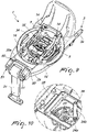
Figure 3 is a view similar to that ofFigure 1 in which a part of the external shell of the car base is removed in order to allow the retention and contrast device to be seen; -
Figures 4 and 5 are enlarged-scale views of some portions of the retention and contrast device shown inFigure 3 ; -
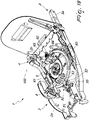
Figure 6 is a cross-sectional view of the car base in the active or use position at the retention and contrast device; -
Figures 7 and 8 are enlarged-scale views of some portions of the retention and contrast device shown inFigure 6 ; -
Figure 9 is a perspective view of the base framework and of a portion of the rotatable supporting body; -
Figure 10 is an enlargement of a portion ofFigure 9 ; -
Figure 11 is a view from above of what is shown inFigure 9 ; -
Figure 12 is a perspective view of the base framework; -
Figure 13 is an enlargement of a portion ofFigure 12 ; -
Figures 14 to 17 are schematic views showing the sequence of operation of the kinematic connection device; -
Figure 18 is a perspective view of the child car seat with a seat element during the step of coupling; -
Figure 19 is a perspective view of the car base, in which a portion of the rotatable supporting body has been omitted, which is positioned in a first active position; -
Figure 20 is a view similar to that ofFigure 19 but with the rotatable supporting body in a second active position. - With reference to the figures, the child car seat according to the invention, particularly for transporting children, generally designated by the
reference numeral 1, comprises acar base 2 which can be associated detachably, viafixing means 3, with a seat of a car. - With reference to the embodiment shown in the figures, the fixing means 3 comprise
fixing tabs 3a which are provided with automatic coupling terminals, for example of the type commercially known as ISO-FIX. - There is no reason why different fixing means cannot be used to fix the
car base 2 to the seat, such as for example means that involve the use of the car safety belt. - The
child car seat 1 further comprises aseat element 10, which can be associated detachably with thecar base 2 via engagement/disengagement means 4 which are known per se. - In particular, the engagement/disengagement means 4 comprise at least one
hook 14 which is supported by thecar base 2 and is configured to engage with arespective engagement element 15 supported by theseat element 10. - Preferably, the engagement/disengagement means 4 comprise a pair of
hooks 14 which are supported by thecar base 2 and are configured to engage with arespective engagement element 15 supported by theseat element 10. - Conveniently, the engagement/disengagement means 4 comprise first and second front and
rear hooks 14 which are arranged on at least onelongitudinal member 5. - Preferably, the engagement/disengagement means 4 are arranged on two
longitudinal members 5, which are mutually parallel and are transversely spaced apart. - The
car base 2 comprises afixed framework 2a which supports, so that it can rotate about anaxis 100 that is vertical during use, a rotatable supportingbody 2b for the engagement/disengagement means 4. - The rotatable supporting
base 2b is adapted to pass from at least one inactive or child loading/unloading position to at least one active or use position. - The at least one inactive position and the at least one active position are mutually angularly spaced apart about the
axis 100. - Specifically, it is advantageous for at least two inactive positions arranged at 180° to each other are possible in order to allow the child to be loaded from both sides of the car.
- It is likewise advantageous that two active positions are possible as well, angularly spaced apart by 90° from the inactive positions, in order to make it possible to arrange the
seat element 10 so that the child is seated against the direction of travel of the car, or facing the direction of travel of the car. - The
fixed framework 2a supports anactuation device 30a which is connected, by means of akinematic connection device 30, to the engagement/disengagement means 4 in order to actuate the at least one pair ofhooks 14 so as to disengage therespective engagement elements 15. - Conveniently, the
actuation device 30a comprises a first movable handle with oscillatory movement about a tilting axis. - There is no reason why the actuation device cannot be operated using different movements or why there cannot be a different actuation system, including a remote-controlled system.
- Advantageously, the
seat 1 comprises at least onelocking device 50 for the automatic locking of the rotatable supportingbody 2b in at least one active or use position. - According to an important aspect of the invention, the
base framework 2a supports at least oneactuation element 51 which is functionally connected to thelocking device 50. - The
actuation element 51 comprises two lateral engagement portions, so that it can be easily moved from both sides of thecar base 2. - The
actuation element 51 is connected, through at least one connecting element constituted by a tension member or by a cable, to means for the relative movement of anengagement body 52, which is supported advantageously so that it can slide by thefixed framework 2a, in order to disengage it from arespective seat 53 defined on the rotatable supportingbody 2b, so as to allow the mutual rotation of the rotatable supportingbody 2b with respect to thefixed framework 2a about theaxis 100. - Preferably, the
actuation element 51 also acts in contrast against elastic contrast means, for example constituted by aspring 55. - Conveniently, the rotatable supporting
body 2b defines twoseats 53. - In particular, the two
seats 53 comprise afirst seat 53a and asecond seat 53b which are angularly spaced apart 180° from each other about theaxis 100. - According to a particularly important aspect of the present invention, a retention and
contrast device 20 is provided for the retention and contrast of the stresses of the rotatable supportingbody 2b in the at least one use position. - In particular, the retention and
contrast device 20 is configured to contrast any stresses that are generated in the event of an accident. - Specifically, in the event of an accident the
seat element 10 is subjected to a compound stress: a first stress force acts substantially parallel to the direction of travel of the vehicle and a second stress force tends to rip theseat element 10 from thebase 2. - In particular, the retention and
contrast device 20 comprises first andsecond engagement teeth 22 which are supported by the rotatable supportingbody 2b and are adapted, when the rotatable supportingbody 2b moves into the use position, to engage in arespective engagement seat 23 defined on thefixed framework 2a. - Obviously, there is no reason why the
engagement teeth 22 cannot be supported by thefixed framework 2a and, as a consequence, theengagement seats 23 would be defined on the rotatable supportingbody 2b. - Specifically, the
engagement teeth 22 extend parallel to the direction of travel of the vehicle and are arranged on opposite sides with respect to theaxis 100. - The
engagement teeth 22 are integral with at least onelongitudinal member 5 and are oriented away from theaxis 100. - Advantageously, the retention and
contrast device 20 comprises a first and a second pair ofengagement teeth 22 which are integral with a respective first and secondlongitudinal member 5 and are oriented away from theaxis 100. - The
engagement seats 23 are U-shaped and are supported, mutually opposite and in pairs, directly by thefixed framework 2a, so that, when the rotatable supportingbody 2b moves to one of the use conditions, theengagement teeth 22 will be accommodated in arespective engagement seat 23. - In such condition for use, any stresses, directed along the direction of travel of the car and tending to rip the
seat element 10 from thecar base 2, are transferred directly to thelongitudinal members 5, supported by the rotatable supportingbody 2b, which are retained directly by thefixed framework 2a by virtue of the coupling between theengagement teeth 22 and therespective engagement seat 23. - In this regard, there can advantageously be a shape mating between the
engagement teeth 22 and therespective engagement seat 23. Such shape mating can be obtained by having the end of each engagement tooth have anupper edge 22a which is directed upward, and having therespective engagement seat 23 have alateral retention edge 23a which is directed downward and at least partially faces, on the end directed toward theaxis 100, theupper edge 22a. - According to a further aspect of the present invention, the at least one
hook 14 can be associated with a first seat element and with a second seat element, different from the first seat element. - In particular, the first seat element comprises an infant seat (also known as a carry cot) and the second seat element comprises a child seat, adapted for children up to a few years old.
- The first seat element is of the type adapted to be used exclusively so that the child is seated facing away from the direction of travel of the car.
- The second seat element is of the type adapted to be used so that the child can be seated facing away from the direction of travel of the car or facing in the direction of travel of the car.
- The engagement/disengagement means 4 are configured to enable the coupling of the second seat element to the
rotatable supporting base 2b in both longitudinal orientations. - The engagement/disengagement means 4 are likewise configured to enable the coupling of the first seat element to the
rotatable supporting base 2b in a single longitudinal orientation. - In this regard, it is possible for the
rotatable supporting base 2b to have at least one region for interfacing with theseat element 10. - In particular, the region for interfacing is contoured so as not to interfere with the external surface of the second seat element if the latter is coupled to the at least one
hook 14 in both longitudinal orientations. - The interface element is configured so as not to interfere with a respective abutment portion defined on the external surface of the first seat element if the latter is arranged so as to face the
rotatable supporting base 2b in order to couple it to the at least onehook 14 in a first longitudinal orientation, while the above mentioned interface element is configured so as to interfere, and consequently prevent the coupling, with the respective abutment portion defined on the external surface of the first seat element if the latter is arranged so as to face therotatable supporting base 2b in order to couple it to the at least onehook 14 in a second longitudinal orientation, which is opposite the first longitudinal orientation. - In this manner, while the second seat element can be associated stably with the at least one
hook 14 in both longitudinal orientations, in the case of the first seat element, typically an infant seat or a carry cot, by virtue of the interface element it is possible to couple the first seat element only in a longitudinal orientation, and this independently of how therotatable supporting base 2b is rotated. - The
rotatable supporting base 2b is associated with closure means for thefirst seat 53a, which are actuated on command following the coupling of the first seat element with thehooks 14. - In particular, when the first seat element is associated, in the only allowed orientation of the longitudinal orientations, with the
rotatable supporting base 2b, an actuation portion, defined on the first seat element, engages anabutment body 61 which is defined on therotatable supporting base 2b and is movable with respect to the above mentionedrotatable supporting base 2b. Theabutment body 61, moving for example with an oscillating motion about an oscillation axis, actuates the closure means which have aterminal portion 62 which, in such condition, prevents access, from outside, to thefirst seat 53a by theengagement body 52. - Arranged between the
terminal portion 62 and theabutment body 61 are kinematic connection elements such as, for example, acable 63 and an interconnectinglever mechanism 64, which is adapted to actuate the displacement of theterminal portion 62. - The terminal portion is also associated with loading means, comprising for example a
spring 65, which are configured to maintain theterminal portion 62 in a condition of disengagement from thefirst seat 53a. - In this manner, when the rotatable supporting
base 2b is associated with the first seat element it will be able to move freely about theaxis 100, but theengagement body 52 will be able to engage exclusively in thesecond seat 53b, which is defined so that, in the single condition for use, the first seat element can be positioned so that the child is seated facing away from the direction of travel of the car. - The
car base 2 is further provided with adisplay device 90 for showing the correct positioning of the seat element in the active position. - Such display device is configured to highlight the correct positioning when the
engagement body 52 is correctly inserted into theengagement seat 53. - Obviously, only the correct engagement of the
engagement body 52 in theengagement seat 53 makes it possible to highlight the correct positioning and, as a consequence, when coupling with the first seat element, the display device makes it possible to ascertain the correct positioning only when the first seat element is arranged so that the child is seated, always, facing away from the direction of travel of the car, all in order to prevent errors by the parent/user. - Conveniently, the
kinematic connection device 30 comprises anelongated element 31 which is connected, at one end, to theactuation device 30a and, at the opposite end, to apusher 32. - For the purposes of example, the
elongated element 31 comprises a tension member; however, there is no reason not to use different solutions, such as for example a sheathed cable. - The
pusher 32 has anengagement portion 32a, which can move, as a consequence of the movement of theactuation device 30a, to engage arotor element 33 which is supported so that it can rotate, about theaxis 100, by the fixedframework 2a. - The
rotor element 33 is further connected, by means of a connectingmember 34, to anactuation body 35 which is supported so that it can slide by therotatable supporting body 2b in order to actuate the at least one pair ofhooks 14. - The
rotor element 33, which is integral in rotation with therotatable supporting body 2b, has a plurality ofactuation tabs 33a, which are arranged angularly spaced apart from each other in a manner corresponding to the angular spacing between the various active and inactive positions of therotatable supporting body 2b, so as to be able to be engaged directly by thepusher 32 independently of the angular position of therotatable supporting body 2b as clearly shown in the operating arrangement illustrated for the purposes of example inFigures 14 to 17 . - With reference to the practical embodiment shown in the figures, since the
rotatable supporting body 2b has two inactive positions and two active positions, theactuation tabs 33a are mutually angularly spaced apart by 90° from each other. - Conveniently, there are first means of
elastic contrast 36, which are configured to contrast the movement of theactuation device 30a. - This makes it possible, once the
actuation device 30a is released, to return the pusher to an inactive position as well, so as to allow, following a new pressing of theactuation device 30a, the engagement with therotor element 33. - Preferably, the first means of
elastic contrast 36 comprise a spring that acts between thepusher 32 and thebase framework 2a. - More specifically, the first means of
elastic contrast 36 comprise a first double-arm torsion spring (also known as a trap-pull spring) which is normally splayed or open. - The
pusher 32 is supported so that it can rotate by the fixedframework 2a about anoscillation axis 101 that is substantially parallel to theaxis 100. - According to a preferred embodiment, a
compensation device 37 is interposed between thepusher 32 and theelongated element 31. - This
compensation device 37 is supported by thepusher 32 so that it can rotate, and it has an engagement tab, which can be oscillated following the pressing of theactuation device 30a to command the oscillation of thepusher 37 about itsown oscillation axis 101. - The first means of
elastic contrast 36 comprise, for example, a trap-pull spring with splayed arms, which can be connected, at an end of a first arm, to the fixedframework 2a, and at the end of the second arm, to atab 32b of thepusher 32. - This
pusher tab 32b is kept resting, by the first means ofelastic contrast 36, against anabutment portion 37a defined on thepusher 37. - Elastic means for positioning and for compensating 38 are likewise provided, which act between the
pusher 32 and thecompensation device 37. - The presence of the
compensation device 37 makes it possible, if the user should rotate therotatable supporting base 2b with theactuation device 30a pressed, not to stress the components that make up thekinematic connection device 30. - Delving deeper into the details, the connecting
member 34 is configured to convert the rotary movement of therotor 33 following the actuation of theactuation device 30a to a translation movement of theactuation body 35 which is supported so that it can slide by therotatable supporting body 2b in order to actuate the release of the at least one pair ofhooks 14. - According to a possible embodiment, the connecting
member 34 comprises a firstelongated body 34a which rotates integrally with therotor 33 and alink rod 34b which is pivoted at the respective ends to the firstelongated body 34a and to theactuation body 35. - Preferably, the
actuation body 35 is mounted so that it can slide on a track defined by therotatable supporting base 2b, so that the rotation on command of therotor element 33 corresponds to a movement of theactuation body 35 along the respective track. - According to a possible further embodiment, the engagement/disengagement means 14 comprise a safety device adapted to prevent the accidental disengagement of the at least one
hook 4 and a device for moving eachhook 4. - In particular, the movement of the
actuation element 35 is adapted to determine, in a first segment of movement, the deactivation of the safety device, and in a second segment of movement, the movement of thehook 14. - The operation of the
child car seat 1, according to the invention, is the following. - The
car base 2 is fixed to the seats of the car using the fixing means 3. - The
rotatable supporting base 2b is rotated to the inactive position, so that theseat element 10 is directed to the side, toward the open door of the car, so as to facilitate the loading and unloading of the child. - When the
seat element 10 is stably associated with therotatable supporting base 2b, thehooks 14 lock onto theengagement elements 15 which are integral with theseat element 10, in order to ensure the fixing of the seat element to the car base. - If the user wishes to bring the
rotatable supporting base 2b (and accordingly the seat element 10) into the active or use position, then the user proceeds to rotate therotatable supporting base 2b about theaxis 100, typically by approximately 90°. - Once this position is reached, the
automatic locking device 20 blocks the rotation about theaxis 100. - In such condition, in order to bring the rotatable supporting base once again to the inactive or loading/unloading position, the user needs to intervene on the
actuation element 51 for mutual disengagement. - If instead the user wishes to uncouple the
seat element 10 from thecar base 2, he or she proceeds by pressing theactuation device 30a, which is directly supported by the fixedframework 2 and is therefore always easily accessible by the user. - Pressing the
actuation device 30a determines the oscillation, about theoscillation axis 101, of thepusher 32, which, with itsengagement portion 32a, makes therotor element 33 rotate about theaxis 100. - The rotation, even though for a limited angular portion, of the
rotor element 33 determines, by virtue of the action of the connectingmember 34, the movement of theactuation body 35, supported so that it can slide by therotatable supporting body 2b, with consequent release of thehooks 14. - It seems evident that the configuration of the kinematic mechanism described makes it possible to release the hooks in all the angular positions (both active and inactive and even intermediate between the active and inactive positions) of the
rotatable supporting base 2b. - In practice it has been found that the invention fully achieves the intended aim and objects by providing a child car seat that is extremely reliable both for the locking in the various different angular positions of the
rotatable supporting body 2a, and, especially, in the operations to release thehooks 14. - Furthermore, the particular shape of the
rotatable supporting base 2b makes it possible to associate the first seat element (typically a carry cot) in a single longitudinal orientation, allowing it to freely rotate about theaxis 100 but allowing it to be locked only in the active position in which the seat element is arranged so that the child is seated facing away from the direction of travel of the car. - Furthermore, by virtue of the presence of the retention and
contrast device 20, any force to which theseat element 10 is subjected during an accident is transferred directly to thelongitudinal members 5, supported by therotatable supporting body 2b, which are retained directly by the fixedframework 2a by virtue of the coupling between theengagement teeth 22 and therespective engagement seat 23. - The invention thus conceived is susceptible of numerous modifications and variations, all of which are within the scope of the appended claims. Moreover, all the details may be substituted by other, technically equivalent elements.
- In practice the materials employed, provided they are compatible with the specific use, and the contingent dimensions and shapes, may be any according to requirements and to the state of the art.
- The disclosures in
Italian Patent Application No. 102020000029648 - Where technical features mentioned in any claim are followed by reference signs, those reference signs have been included for the sole purpose of increasing the intelligibility of the claims and accordingly, such reference signs do not have any limiting effect on the interpretation of each element identified by way of example by such reference signs.
Claims (10)
- A child car seat (1), particularly for transporting children, which comprises a car base (2) which can be associated detachably, via fixing means (3), with a seat of a car, and a seat element (10), which can be associated detachably with said car base (2) via engagement/disengagement means (4) supported by said car base (2) which comprise at least one hook (14) configured to engage a respective engagement element (15) supported by said seat element (10), said car base (2) comprising a fixed framework (2a) which supports, so that it can rotate about an axis (100) that is vertical during use, a rotatable supporting body (2b) for said at least one hook (14) which is adapted to pass from at least one inactive or child loading/unloading position to at least two active or use positions, said at least one inactive position and said at least two active positions being mutually angularly spaced apart around said axis (100), said child car seat (1) comprising at least one locking device (50) for the automatic locking of said rotatable supporting body (2b) in at least one of said active or use positions, said base framework (2a) supporting at least one actuation element (51), which is functionally connected to said locking device (50) and is connected to an engagement body (52) in order to disengage it from a respective seat (53) defined on said rotatable supporting body (2b), so as to allow the mutual rotation of said rotatable supporting body (2b) with respect to said fixed framework (2a) about said axis (100), said two seats (53) comprising a first seat (53a) and a second seat (53b) which are angularly mutually spaced apart around said axis (100), said at least one hook (14) can be associated with a first seat element and with a second seat element, different from the first seat element, said first seat element being of the type adapted to be used exclusively so that the child sits against the direction of travel of the car and said second seat element being of the type adapted to be used so that the child can sit against the direction of travel of the car or facing the direction of travel of the car, characterized in that said engagement/disengagement means (4) are configured to allow the coupling of said second seat element to said rotatable supporting base (2b) in both longitudinal directions and of said first seat element to said rotatable supporting base (2b) in only one longitudinal orientation, said rotatable supporting base (2b) being associated with closure means for said first seat (53a), said closure means being actuated on command following the coupling of said first seat element with said at least one hook (14).
- The child car seat (1) according to claim 1, characterized in that said at least one hook (14) is defined on at least one longitudinal member (5) which is supported by said car base (2) and is configured to engage a respective engagement element (15) supported by said seat element (10), a retention and contrast device (20) for the retention and contrast of the stresses of the rotatable supporting body (2b) in the at least one use position being provided and being configured to contrast any stresses, said retention and contrast device (20) comprising at least one first engagement tooth and at least one second engagement tooth (22) which are supported by the rotatable supporting body (2b) and are adapted, when said rotatable supporting body (2b) moves into the use position, to engage a respective engagement seat (23) defined on said fixed framework (2a), said at least two engagement teeth (22) being integral with at least one respective longitudinal member (5) and being oriented away from the axis (100).
- The child car seat (1) according to claim 1 or 2, characterized in that said fixed framework (2a) supports an actuation device (30a) which is connected, by means of a kinematic connection device (30), to said engagement/disengagement means (4) in order to actuate said at least one hook (14) so as to disengage the respective engagement element (15), said kinematic connection device (30) comprising an elongated element (31) which is connected, at one end, to said actuation device (30a) and, at the opposite end, to a pusher (32) which has an engagement portion (32a) which can move, as a consequence of the movement of said actuation device (30a), to engage a rotor element (33) which is supported so that it can rotate, about said axis (100), by said fixed framework (2a), said rotor element (33) being connected, by means of a connecting member (34), to an actuation body (35) which is supported so that it can slide by said rotatable supporting body (2b) in order to actuate said at least one hook (14).
- The child car seat (1) according to one or more of the preceding claims, characterized in that said engagement seats (23) are U-shaped and are supported, mutually opposite and in pairs, directly by said fixed framework (2a).
- The child car seat (1) according to one or more of the preceding claims, characterized in that said actuation element (51) acts in contrast with elastic contrast means.
- The child car seat (1) according to one or more of the preceding claims, characterized in that it comprises a shape mating between said engagement teeth (22) and the respective engagement seat (23).
- The child car seat (1) according to one or more of the preceding claims, characterized in that said shape mating entails that the end of each engagement tooth (22) has an upper edge (22a) which is directed upward, and that the respective engagement seat (23) has a lateral retention edge (23a) which is directed downward and at least partially faces, on the end directed toward the axis (100), the respective upper edge (22a).
- The child car seat (1) according to one or more of the preceding claims, characterized in that said first seat element comprises an infant seat and said second seat element comprises a child seat.
- The child car seat (1) according to one or more of the preceding claims, characterized in that said rotatable supporting base (2b) comprises at least one region for interfacing with said seat element (10), said region for interfacing being shaped so as not to interfere with the external surface of said second seat element if the latter is coupled to said at least one hook (14) in both longitudinal orientations and being configured so as not to interfere with a respective abutment portion defined on the external surface of said first seat element if the latter is arranged so as to face said rotatable supporting base (2b) in order to couple it to said at least one hook (14) in a first longitudinal orientation, said interface element being configured so as to interfere with the respective abutment portion defined on the external surface of said first seat element if the latter is arranged so as to face said rotatable supporting base (2b) in order to couple it to said at least one hook (14) in a second longitudinal orientation, which is opposite the first longitudinal orientation.
- The child car seat (1) according to one or more of the preceding claims, characterized in that said closure means are actuated on command following the coupling of said first seat element with said at least one hook (14) in the only allowed orientation of the longitudinal orientations, by means of an actuation portion which is defined on said first seat element, and which engages an abutment body which is defined on the rotatable supporting base (2b) and is movable with respect to said rotatable supporting base (2b), said closure means having a terminal portion adapted to prevent access to said first seat (53a) by said engagement body (52).
Applications Claiming Priority (1)
| Application Number | Priority Date | Filing Date | Title |
|---|---|---|---|
| IT202000029648 | 2020-12-03 |
Publications (3)
| Publication Number | Publication Date |
|---|---|
| EP4008583A1 true EP4008583A1 (en) | 2022-06-08 |
| EP4008583C0 EP4008583C0 (en) | 2023-06-14 |
| EP4008583B1 EP4008583B1 (en) | 2023-06-14 |
Family
ID=74669340
Family Applications (1)
| Application Number | Title | Priority Date | Filing Date |
|---|---|---|---|
| EP21210818.7A Active EP4008583B1 (en) | 2020-12-03 | 2021-11-26 | Child car seat |
Country Status (1)
| Country | Link |
|---|---|
| EP (1) | EP4008583B1 (en) |
Cited By (1)
| Publication number | Priority date | Publication date | Assignee | Title |
|---|---|---|---|---|
| WO2025093405A1 (en) * | 2023-10-30 | 2025-05-08 | Cybex Gmbh | Child seat, and child seat base |
Citations (2)
| Publication number | Priority date | Publication date | Assignee | Title |
|---|---|---|---|---|
| CN110497826A (en) * | 2019-09-27 | 2019-11-26 | 创是实业(香港)有限公司 | Safety seat pedestal manipulation component, safety seat pedestal, external member and control method |
| US20200215941A1 (en) * | 2017-09-14 | 2020-07-09 | Cybex Gmbh | Child seat system |
-
2021
- 2021-11-26 EP EP21210818.7A patent/EP4008583B1/en active Active
Patent Citations (2)
| Publication number | Priority date | Publication date | Assignee | Title |
|---|---|---|---|---|
| US20200215941A1 (en) * | 2017-09-14 | 2020-07-09 | Cybex Gmbh | Child seat system |
| CN110497826A (en) * | 2019-09-27 | 2019-11-26 | 创是实业(香港)有限公司 | Safety seat pedestal manipulation component, safety seat pedestal, external member and control method |
Cited By (1)
| Publication number | Priority date | Publication date | Assignee | Title |
|---|---|---|---|---|
| WO2025093405A1 (en) * | 2023-10-30 | 2025-05-08 | Cybex Gmbh | Child seat, and child seat base |
Also Published As
| Publication number | Publication date |
|---|---|
| EP4008583C0 (en) | 2023-06-14 |
| EP4008583B1 (en) | 2023-06-14 |
Similar Documents
| Publication | Publication Date | Title |
|---|---|---|
| EP3733478B1 (en) | Baby stroller with a folding mechanism triggered by a child carrier | |
| US12545154B2 (en) | Safety seat having a spin lock | |
| US8556344B2 (en) | Child safety seat assembly | |
| AU2023285807B2 (en) | Wheeled carrying apparatus | |
| US5743596A (en) | Safety fixture for removable seat of the vehicle | |
| KR20060041979A (en) | Lock mechanism of the child seat and child seat fixing device of the stroller | |
| GB2482061A (en) | Child safety seat assembly | |
| EP2664491B1 (en) | Support base for a child safety seat | |
| JP5215594B2 (en) | Double lock caster | |
| EP4008583B1 (en) | Child car seat | |
| US7726731B2 (en) | Device for removably fitting to prams carrycot seats and carrycots being provided with an articulated handle | |
| JPS6339472B2 (en) | ||
| JP4312496B2 (en) | child seat | |
| KR102770306B1 (en) | Locking device for swivel seat | |
| JP5251268B2 (en) | Vehicle seat | |
| AU2025201753A1 (en) | Device for preventing mis-rotation and seat | |
| CN104918822A (en) | Foldable head rest assembly | |
| CN220996192U (en) | Base for a child restraint system, child seat connectable to the base, and child restraint system | |
| US6183001B1 (en) | Device for attaching a support to a child's pushchair, pushchair and support equipped with such a device | |
| CN218505689U (en) | Children car seat | |
| KR20230111248A (en) | Infant carriers and height adjustment devices | |
| CN104203031A (en) | Belt buckle with release lock | |
| JP2024542710A (en) | A child seat base for receiving a seat element | |
| US20050077765A1 (en) | Child car seat inclining and swivelling between a travelling position and an installing position | |
| EP4703198A1 (en) | Child seat |
Legal Events
| Date | Code | Title | Description |
|---|---|---|---|
| PUAI | Public reference made under article 153(3) epc to a published international application that has entered the european phase |
Free format text: ORIGINAL CODE: 0009012 |
|
| STAA | Information on the status of an ep patent application or granted ep patent |
Free format text: STATUS: THE APPLICATION HAS BEEN PUBLISHED |
|
| AK | Designated contracting states |
Kind code of ref document: A1 Designated state(s): AL AT BE BG CH CY CZ DE DK EE ES FI FR GB GR HR HU IE IS IT LI LT LU LV MC MK MT NL NO PL PT RO RS SE SI SK SM TR |
|
| STAA | Information on the status of an ep patent application or granted ep patent |
Free format text: STATUS: REQUEST FOR EXAMINATION WAS MADE |
|
| 17P | Request for examination filed |
Effective date: 20220829 |
|
| RBV | Designated contracting states (corrected) |
Designated state(s): AL AT BE BG CH CY CZ DE DK EE ES FI FR GB GR HR HU IE IS IT LI LT LU LV MC MK MT NL NO PL PT RO RS SE SI SK SM TR |
|
| RIC1 | Information provided on ipc code assigned before grant |
Ipc: B60N 2/28 20060101AFI20221216BHEP |
|
| GRAP | Despatch of communication of intention to grant a patent |
Free format text: ORIGINAL CODE: EPIDOSNIGR1 |
|
| STAA | Information on the status of an ep patent application or granted ep patent |
Free format text: STATUS: GRANT OF PATENT IS INTENDED |
|
| INTG | Intention to grant announced |
Effective date: 20230130 |
|
| GRAS | Grant fee paid |
Free format text: ORIGINAL CODE: EPIDOSNIGR3 |
|
| GRAA | (expected) grant |
Free format text: ORIGINAL CODE: 0009210 |
|
| STAA | Information on the status of an ep patent application or granted ep patent |
Free format text: STATUS: THE PATENT HAS BEEN GRANTED |
|
| AK | Designated contracting states |
Kind code of ref document: B1 Designated state(s): AL AT BE BG CH CY CZ DE DK EE ES FI FR GB GR HR HU IE IS IT LI LT LU LV MC MK MT NL NO PL PT RO RS SE SI SK SM TR |
|
| REG | Reference to a national code |
Ref country code: CH Ref legal event code: EP |
|
| REG | Reference to a national code |
Ref country code: DE Ref legal event code: R096 Ref document number: 602021002937 Country of ref document: DE |
|
| REG | Reference to a national code |
Ref country code: AT Ref legal event code: REF Ref document number: 1579016 Country of ref document: AT Kind code of ref document: T Effective date: 20230715 |
|
| U01 | Request for unitary effect filed |
Effective date: 20230712 |
|
| U07 | Unitary effect registered |
Designated state(s): AT BE BG DE DK EE FI FR IT LT LU LV MT NL PT SE SI Effective date: 20230726 |
|
| REG | Reference to a national code |
Ref country code: LT Ref legal event code: MG9D |
|
| PG25 | Lapsed in a contracting state [announced via postgrant information from national office to epo] |
Ref country code: NO Free format text: LAPSE BECAUSE OF FAILURE TO SUBMIT A TRANSLATION OF THE DESCRIPTION OR TO PAY THE FEE WITHIN THE PRESCRIBED TIME-LIMIT Effective date: 20230914 Ref country code: ES Free format text: LAPSE BECAUSE OF FAILURE TO SUBMIT A TRANSLATION OF THE DESCRIPTION OR TO PAY THE FEE WITHIN THE PRESCRIBED TIME-LIMIT Effective date: 20230614 |
|
| PG25 | Lapsed in a contracting state [announced via postgrant information from national office to epo] |
Ref country code: RS Free format text: LAPSE BECAUSE OF FAILURE TO SUBMIT A TRANSLATION OF THE DESCRIPTION OR TO PAY THE FEE WITHIN THE PRESCRIBED TIME-LIMIT Effective date: 20230614 Ref country code: HR Free format text: LAPSE BECAUSE OF FAILURE TO SUBMIT A TRANSLATION OF THE DESCRIPTION OR TO PAY THE FEE WITHIN THE PRESCRIBED TIME-LIMIT Effective date: 20230614 Ref country code: GR Free format text: LAPSE BECAUSE OF FAILURE TO SUBMIT A TRANSLATION OF THE DESCRIPTION OR TO PAY THE FEE WITHIN THE PRESCRIBED TIME-LIMIT Effective date: 20230915 |
|
| U20 | Renewal fee for the european patent with unitary effect paid |
Year of fee payment: 3 Effective date: 20231122 |
|
| PG25 | Lapsed in a contracting state [announced via postgrant information from national office to epo] |
Ref country code: SK Free format text: LAPSE BECAUSE OF FAILURE TO SUBMIT A TRANSLATION OF THE DESCRIPTION OR TO PAY THE FEE WITHIN THE PRESCRIBED TIME-LIMIT Effective date: 20230614 |
|
| PG25 | Lapsed in a contracting state [announced via postgrant information from national office to epo] |
Ref country code: IS Free format text: LAPSE BECAUSE OF FAILURE TO SUBMIT A TRANSLATION OF THE DESCRIPTION OR TO PAY THE FEE WITHIN THE PRESCRIBED TIME-LIMIT Effective date: 20231014 |
|
| PG25 | Lapsed in a contracting state [announced via postgrant information from national office to epo] |
Ref country code: SM Free format text: LAPSE BECAUSE OF FAILURE TO SUBMIT A TRANSLATION OF THE DESCRIPTION OR TO PAY THE FEE WITHIN THE PRESCRIBED TIME-LIMIT Effective date: 20230614 Ref country code: SK Free format text: LAPSE BECAUSE OF FAILURE TO SUBMIT A TRANSLATION OF THE DESCRIPTION OR TO PAY THE FEE WITHIN THE PRESCRIBED TIME-LIMIT Effective date: 20230614 Ref country code: RO Free format text: LAPSE BECAUSE OF FAILURE TO SUBMIT A TRANSLATION OF THE DESCRIPTION OR TO PAY THE FEE WITHIN THE PRESCRIBED TIME-LIMIT Effective date: 20230614 Ref country code: IS Free format text: LAPSE BECAUSE OF FAILURE TO SUBMIT A TRANSLATION OF THE DESCRIPTION OR TO PAY THE FEE WITHIN THE PRESCRIBED TIME-LIMIT Effective date: 20231014 Ref country code: CZ Free format text: LAPSE BECAUSE OF FAILURE TO SUBMIT A TRANSLATION OF THE DESCRIPTION OR TO PAY THE FEE WITHIN THE PRESCRIBED TIME-LIMIT Effective date: 20230614 |
|
| PG25 | Lapsed in a contracting state [announced via postgrant information from national office to epo] |
Ref country code: PL Free format text: LAPSE BECAUSE OF FAILURE TO SUBMIT A TRANSLATION OF THE DESCRIPTION OR TO PAY THE FEE WITHIN THE PRESCRIBED TIME-LIMIT Effective date: 20230614 |
|
| REG | Reference to a national code |
Ref country code: DE Ref legal event code: R097 Ref document number: 602021002937 Country of ref document: DE |
|
| PLBE | No opposition filed within time limit |
Free format text: ORIGINAL CODE: 0009261 |
|
| STAA | Information on the status of an ep patent application or granted ep patent |
Free format text: STATUS: NO OPPOSITION FILED WITHIN TIME LIMIT |
|
| 26N | No opposition filed |
Effective date: 20240315 |
|
| PG25 | Lapsed in a contracting state [announced via postgrant information from national office to epo] |
Ref country code: MC Free format text: LAPSE BECAUSE OF FAILURE TO SUBMIT A TRANSLATION OF THE DESCRIPTION OR TO PAY THE FEE WITHIN THE PRESCRIBED TIME-LIMIT Effective date: 20230614 |
|
| PG25 | Lapsed in a contracting state [announced via postgrant information from national office to epo] |
Ref country code: MC Free format text: LAPSE BECAUSE OF FAILURE TO SUBMIT A TRANSLATION OF THE DESCRIPTION OR TO PAY THE FEE WITHIN THE PRESCRIBED TIME-LIMIT Effective date: 20230614 |
|
| REG | Reference to a national code |
Ref country code: IE Ref legal event code: MM4A |
|
| PG25 | Lapsed in a contracting state [announced via postgrant information from national office to epo] |
Ref country code: IE Free format text: LAPSE BECAUSE OF NON-PAYMENT OF DUE FEES Effective date: 20231126 |
|
| PG25 | Lapsed in a contracting state [announced via postgrant information from national office to epo] |
Ref country code: IE Free format text: LAPSE BECAUSE OF NON-PAYMENT OF DUE FEES Effective date: 20231126 |
|
| U20 | Renewal fee for the european patent with unitary effect paid |
Year of fee payment: 4 Effective date: 20241120 |
|
| REG | Reference to a national code |
Ref country code: CH Ref legal event code: PL |
|
| REG | Reference to a national code |
Ref country code: CH Ref legal event code: PL |
|
| PG25 | Lapsed in a contracting state [announced via postgrant information from national office to epo] |
Ref country code: CH Free format text: LAPSE BECAUSE OF NON-PAYMENT OF DUE FEES Effective date: 20241130 |
|
| PG25 | Lapsed in a contracting state [announced via postgrant information from national office to epo] |
Ref country code: CY Free format text: LAPSE BECAUSE OF FAILURE TO SUBMIT A TRANSLATION OF THE DESCRIPTION OR TO PAY THE FEE WITHIN THE PRESCRIBED TIME-LIMIT; INVALID AB INITIO Effective date: 20211126 |
|
| PG25 | Lapsed in a contracting state [announced via postgrant information from national office to epo] |
Ref country code: TR Free format text: LAPSE BECAUSE OF FAILURE TO SUBMIT A TRANSLATION OF THE DESCRIPTION OR TO PAY THE FEE WITHIN THE PRESCRIBED TIME-LIMIT Effective date: 20230614 |
|
| U20 | Renewal fee for the european patent with unitary effect paid |
Year of fee payment: 5 Effective date: 20251120 |
|
| PGFP | Annual fee paid to national office [announced via postgrant information from national office to epo] |
Ref country code: GB Payment date: 20251119 Year of fee payment: 5 |
|
| PG25 | Lapsed in a contracting state [announced via postgrant information from national office to epo] |
Ref country code: HU Free format text: LAPSE BECAUSE OF FAILURE TO SUBMIT A TRANSLATION OF THE DESCRIPTION OR TO PAY THE FEE WITHIN THE PRESCRIBED TIME-LIMIT; INVALID AB INITIO Effective date: 20211126 |