EP4008558A1 - Tag writing device, label printer, and information processing program - Google Patents
Tag writing device, label printer, and information processing program Download PDFInfo
- Publication number
- EP4008558A1 EP4008558A1 EP21179740.2A EP21179740A EP4008558A1 EP 4008558 A1 EP4008558 A1 EP 4008558A1 EP 21179740 A EP21179740 A EP 21179740A EP 4008558 A1 EP4008558 A1 EP 4008558A1
- Authority
- EP
- European Patent Office
- Prior art keywords
- antenna
- mount
- wireless tags
- wireless
- component
- Prior art date
- Legal status (The legal status is an assumption and is not a legal conclusion. Google has not performed a legal analysis and makes no representation as to the accuracy of the status listed.)
- Granted
Links
Images




Classifications
-
- B—PERFORMING OPERATIONS; TRANSPORTING
- B41—PRINTING; LINING MACHINES; TYPEWRITERS; STAMPS
- B41J—TYPEWRITERS; SELECTIVE PRINTING MECHANISMS, i.e. MECHANISMS PRINTING OTHERWISE THAN FROM A FORME; CORRECTION OF TYPOGRAPHICAL ERRORS
- B41J3/00—Typewriters or selective printing or marking mechanisms characterised by the purpose for which they are constructed
- B41J3/44—Typewriters or selective printing mechanisms having dual functions or combined with, or coupled to, apparatus performing other functions
- B41J3/50—Mechanisms producing characters by printing and also producing a record by other means, e.g. printer combined with RFID writer
-
- G—PHYSICS
- G06—COMPUTING OR CALCULATING; COUNTING
- G06K—GRAPHICAL DATA READING; PRESENTATION OF DATA; RECORD CARRIERS; HANDLING RECORD CARRIERS
- G06K15/00—Arrangements for producing a permanent visual presentation of the output data, e.g. computer output printers
- G06K15/02—Arrangements for producing a permanent visual presentation of the output data, e.g. computer output printers using printers
- G06K15/028—Arrangements for producing a permanent visual presentation of the output data, e.g. computer output printers using printers by thermal printers
-
- B—PERFORMING OPERATIONS; TRANSPORTING
- B41—PRINTING; LINING MACHINES; TYPEWRITERS; STAMPS
- B41J—TYPEWRITERS; SELECTIVE PRINTING MECHANISMS, i.e. MECHANISMS PRINTING OTHERWISE THAN FROM A FORME; CORRECTION OF TYPOGRAPHICAL ERRORS
- B41J3/00—Typewriters or selective printing or marking mechanisms characterised by the purpose for which they are constructed
- B41J3/407—Typewriters or selective printing or marking mechanisms characterised by the purpose for which they are constructed for marking on special material
- B41J3/4075—Tape printers; Label printers
-
- G—PHYSICS
- G01—MEASURING; TESTING
- G01S—RADIO DIRECTION-FINDING; RADIO NAVIGATION; DETERMINING DISTANCE OR VELOCITY BY USE OF RADIO WAVES; LOCATING OR PRESENCE-DETECTING BY USE OF THE REFLECTION OR RERADIATION OF RADIO WAVES; ANALOGOUS ARRANGEMENTS USING OTHER WAVES
- G01S5/00—Position-fixing by co-ordinating two or more direction or position line determinations; Position-fixing by co-ordinating two or more distance determinations
- G01S5/02—Position-fixing by co-ordinating two or more direction or position line determinations; Position-fixing by co-ordinating two or more distance determinations using radio waves
- G01S5/0284—Relative positioning
-
- G—PHYSICS
- G01—MEASURING; TESTING
- G01S—RADIO DIRECTION-FINDING; RADIO NAVIGATION; DETERMINING DISTANCE OR VELOCITY BY USE OF RADIO WAVES; LOCATING OR PRESENCE-DETECTING BY USE OF THE REFLECTION OR RERADIATION OF RADIO WAVES; ANALOGOUS ARRANGEMENTS USING OTHER WAVES
- G01S5/00—Position-fixing by co-ordinating two or more direction or position line determinations; Position-fixing by co-ordinating two or more distance determinations
- G01S5/02—Position-fixing by co-ordinating two or more direction or position line determinations; Position-fixing by co-ordinating two or more distance determinations using radio waves
- G01S5/0295—Proximity-based methods, e.g. position inferred from reception of particular signals
-
- G—PHYSICS
- G06—COMPUTING OR CALCULATING; COUNTING
- G06K—GRAPHICAL DATA READING; PRESENTATION OF DATA; RECORD CARRIERS; HANDLING RECORD CARRIERS
- G06K15/00—Arrangements for producing a permanent visual presentation of the output data, e.g. computer output printers
- G06K15/02—Arrangements for producing a permanent visual presentation of the output data, e.g. computer output printers using printers
- G06K15/16—Means for paper feeding or form feeding
-
- G—PHYSICS
- G06—COMPUTING OR CALCULATING; COUNTING
- G06K—GRAPHICAL DATA READING; PRESENTATION OF DATA; RECORD CARRIERS; HANDLING RECORD CARRIERS
- G06K17/00—Methods or arrangements for effecting co-operative working between equipments covered by two or more of main groups G06K1/00 - G06K15/00, e.g. automatic card files incorporating conveying and reading operations
- G06K17/0022—Methods or arrangements for effecting co-operative working between equipments covered by two or more of main groups G06K1/00 - G06K15/00, e.g. automatic card files incorporating conveying and reading operations arrangements or provisions for transferring data to distant stations, e.g. from a sensing device
- G06K17/0025—Methods or arrangements for effecting co-operative working between equipments covered by two or more of main groups G06K1/00 - G06K15/00, e.g. automatic card files incorporating conveying and reading operations arrangements or provisions for transferring data to distant stations, e.g. from a sensing device the arrangement consisting of a wireless interrogation device in combination with a device for optically marking the record carrier
-
- G—PHYSICS
- G06—COMPUTING OR CALCULATING; COUNTING
- G06K—GRAPHICAL DATA READING; PRESENTATION OF DATA; RECORD CARRIERS; HANDLING RECORD CARRIERS
- G06K19/00—Record carriers for use with machines and with at least a part designed to carry digital markings
- G06K19/06—Record carriers for use with machines and with at least a part designed to carry digital markings characterised by the kind of the digital marking, e.g. shape, nature, code
- G06K19/067—Record carriers with conductive marks, printed circuits or semiconductor circuit elements, e.g. credit or identity cards also with resonating or responding marks without active components
- G06K19/07—Record carriers with conductive marks, printed circuits or semiconductor circuit elements, e.g. credit or identity cards also with resonating or responding marks without active components with integrated circuit chips
- G06K19/077—Constructional details, e.g. mounting of circuits in the carrier
- G06K19/07749—Constructional details, e.g. mounting of circuits in the carrier the record carrier being capable of non-contact communication, e.g. constructional details of the antenna of a non-contact smart card
-
- G—PHYSICS
- G06—COMPUTING OR CALCULATING; COUNTING
- G06F—ELECTRIC DIGITAL DATA PROCESSING
- G06F3/00—Input arrangements for transferring data to be processed into a form capable of being handled by the computer; Output arrangements for transferring data from processing unit to output unit, e.g. interface arrangements
- G06F3/12—Digital output to print unit, e.g. line printer, chain printer
- G06F3/1201—Dedicated interfaces to print systems
- G06F3/1202—Dedicated interfaces to print systems specifically adapted to achieve a particular effect
- G06F3/1203—Improving or facilitating administration, e.g. print management
- G06F3/1208—Improving or facilitating administration, e.g. print management resulting in improved quality of the output result, e.g. print layout, colours, workflows, print preview
-
- G—PHYSICS
- G06—COMPUTING OR CALCULATING; COUNTING
- G06F—ELECTRIC DIGITAL DATA PROCESSING
- G06F3/00—Input arrangements for transferring data to be processed into a form capable of being handled by the computer; Output arrangements for transferring data from processing unit to output unit, e.g. interface arrangements
- G06F3/12—Digital output to print unit, e.g. line printer, chain printer
- G06F3/1201—Dedicated interfaces to print systems
- G06F3/1223—Dedicated interfaces to print systems specifically adapted to use a particular technique
- G06F3/1237—Print job management
- G06F3/125—Page layout or assigning input pages onto output media, e.g. imposition
-
- G—PHYSICS
- G06—COMPUTING OR CALCULATING; COUNTING
- G06F—ELECTRIC DIGITAL DATA PROCESSING
- G06F3/00—Input arrangements for transferring data to be processed into a form capable of being handled by the computer; Output arrangements for transferring data from processing unit to output unit, e.g. interface arrangements
- G06F3/12—Digital output to print unit, e.g. line printer, chain printer
- G06F3/1201—Dedicated interfaces to print systems
- G06F3/1278—Dedicated interfaces to print systems specifically adapted to adopt a particular infrastructure
- G06F3/1285—Remote printer device, e.g. being remote from client or server
Definitions
- Embodiments described herein relate generally to a tag writing device, a label printer, and an information processing program.
- One of the objects of the present invention is to improve prior art techniques and overcome at least some of the prior art problems as for instance above illustrated.
- a tag writing device comprising a conveying component configured to convey a mount, to which a plurality of wireless tags are attached in a row at about equal intervals, along an array direction of the plurality of wireless tags; an antenna opposed to the mount conveyed by the conveying component, the antenna being provided for wireless communication with a plurality of wireless tags located within a communication range among the plurality of wireless tags; an acquiring component configured to acquire, in a period in which the mount is conveyed by the conveying component from a predetermined start position to a predetermined end position, a plurality of times each time the mount is conveyed by the conveying component by a fixed amount, reception intensities in the antenna of radio signals transmitted from the plurality of wireless tags; a determining component configured to determine, concerning each of the plurality of wireless tags, an intermediate position between the start position and the end position as a position where a sum of reception intensities acquired by the acquiring component while the mount is conveyed from the start position to the
- the determining component determines the intermediate position by an arithmetic operation.
- the plurality of wireless tags are attached in at about 1 cm intervals.
- the plurality of wireless tags are radio frequency identification wireless tags.
- a label printer comprising a conveying component configured to convey a mount, to which a plurality of label papers respectively attached with wireless tags are stuck in a row at about equal intervals, along an array direction of the plurality of label papers; a print component configured to print an image on the label paper; an antenna opposed to the mount conveyed by the conveying component, the antenna being provided for wireless communication with a plurality of wireless tags located within a communication range among the plurality of wireless tags; an acquiring component configured to acquire, in a period in which the mount is conveyed by the conveying component from a predetermined start position to a predetermined end position, a plurality of times each time the mount is conveyed by the conveying component by a fixed amount, reception intensities in the antenna of radio signals transmitted from the plurality of wireless tags; a determining component configured to determine, concerning each of the plurality of wireless tags, an intermediate position between the start position and the end position as a position where a sum of reception intensities acquired by
- the determining component determines the intermediate position by an arithmetic operation.
- the plurality of wireless tags are attached in at about 1 cm intervals.
- the plurality of wireless tags are radio frequency identification wireless tags.
- the print component is a thermal-type print head.
- an information processing method for a tag writing device comprising acquiring, in a period in which a mount, to which a plurality of wireless tags are attached in a row at equal intervals, along an array direction of the plurality of wireless tags, is conveyed by a conveying component from a predetermined start position to a predetermined end position, a plurality of times each time the mount is conveyed by the conveying component by a fixed amount, reception intensities in an antenna of radio signals transmitted from the plurality of wireless tags, the antenna being provided for wireless communication with a plurality of wireless tags located within a communication range among the plurality of wireless tags; determining, concerning each of the plurality of wireless tags, an intermediate position between the start position and the end position as a position where a sum of reception intensities acquired while the mount is conveyed from the start position to the intermediate position by the conveying component and a sum of reception intensities acquired while the mount is conveyed from the intermediate position to the end position by the conveying component are
- a tag writing device comprising: a conveying component configured to convey a mount, to which a plurality of wireless tags are attached in a row at about equal intervals, along an array direction of the plurality of wireless tags; an antenna opposed to the mount conveyed by the conveying component, the antenna being provided for wireless communication with one or a plurality of wireless tags located within a communication range among the plurality of wireless tags; a cutting component configured to cut the mount in a direction crossing the array direction; a controller configured to set an end portion of the mount formed by being cut by the cutting unit to be opposed to the antenna and, thereafter, control the conveying component to convey the mount while causing the mount to pass a position opposed to the antenna; an acquiring component configured to, if the mount is conveyed by the conveying component while passing the position opposed to the antenna, acquire, a plurality of times, reception intensities in the antenna of radio signals transmitted from the plurality of wireless tags; a selecting component configured to, if reception intensity matching a
- the determining component determines the intermediate position by an arithmetic operation.
- the plurality of wireless tags are attached in at about 1 cm intervals.
- the plurality of wireless tags are radio frequency identification wireless tags.
- a label printer comprising: a conveying component configured to convey a mount, to which a plurality of label papers respectively attached with wireless tags are stuck in a row at about equal intervals, along an array direction of the plurality of label papers; a print component configured to print an image on the label paper; an antenna opposed to the mount conveyed by the conveying component, the antenna being provided for wireless communication with one or a plurality of wireless tags located within a communication range among the plurality of wireless tags; a cutting component configured to cut the mount in a direction crossing the array direction; a controller configured to set an end portion of the mount formed by being cut by the cutting component to be opposed to the antenna and, thereafter, control the conveying unit to convey the mount while causing the mount to pass a position opposed to the antenna; an acquiring component configured to, if the mount is conveyed by the conveying component while being caused to pass the position opposed to the antenna, acquire, a plurality of times, reception intensities in the antenna of radio signals transmitted from
- the determining component determines the intermediate position by an arithmetic operation.
- the plurality of wireless tags are attached in at about 1 cm intervals.
- the plurality of wireless tags are radio frequency identification wireless tags.
- the print component is a thermal-type print head.
- an information processing method for a tag writing device comprising:
- An aspect of embodiments is to provide, in order to solve the problems described above, a tag writing device, a label printer, and an information processing program that can correctly perform calibration for determining an optimum relative positional relation between a wireless tag and an antenna.
- a tag writing device includes a conveying unit, an antenna, an acquiring unit, a determining unit, a selecting unit, and a deciding unit.
- the conveying unit conveys a mount, to which a plurality of wireless tags are attached in a row at equal intervals, along an array direction of the plurality of wireless tags.
- the antenna is disposed to be opposed to the mount conveyed by the conveying unit and is provided for wireless communication with a plurality of wireless tags located within a communication range among the plurality of wireless tags.
- the acquiring unit acquires, in a period in which the mount is conveyed by the conveying unit from a predetermined start position to a predetermined end position, a plurality of times every time the mount is conveyed by the conveying unit by a fixed amount, reception intensities in the antenna of radio signals transmitted from the plurality of wireless tags.
- the determining unit determines, concerning each of the plurality of wireless tags, an intermediate position between the start position and the end position as a position where a sum of reception intensities acquired by the acquiring unit while the mount is conveyed from the start position to the intermediate position by the conveying unit and a sum of reception intensities acquired by the acquiring unit while the mount is conveyed from the intermediate position to the end position by the conveying unit are closest.
- the selecting unit selects, as a target tag, the wireless tag, the intermediate position of which is determined by the determining unit as a position within a prediction range predetermined as a range included in a range between the start position and the end position.
- the deciding unit decides, based on reception intensity in the antenna of a radio signal transmitted from the target tag selected by the selecting unit, a relative positional relation between the wireless tag and the antenna at a time when writing is performed in one of the plurality of wireless tags.
- FIG. 1 is a diagram illustrating the structure of a part of and a main part circuit configuration of a label printer 100 according to a first embodiment.
- the label printer 100 prints, while conveying an elongated mount MO, an image representing characters and the like on label paper RA stuck to one surface (hereinafter referred to as front surface) of the mount MO.
- the label printer 100 writes data in a wireless tag attached to the label paper RA.
- the material of the mount MO and the label paper RA is typically paper but may be a material other than the paper such as resin.
- the materials of the mount MO and the label paper RA may be different from each other.
- the label paper RA is heat-sensitive paper.
- the wireless tag for example, an RFID (radio frequency identifier) tag can be used.
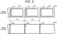
- FIG. 2 is a diagram illustrating the exteriors of a front surface and a rear surface of the mount MO.
- a plurality of label papers RA are stuck to the front surface of the mount MO in a row at equal intervals along the longitudinal direction of the mount MO. That is, the plurality of label papers RA are arranged on the front surface of the mount MO in a row at a pitch PI.
- the longitudinal direction of the mount MO is simply referred to as "longitudinal direction”.
- a wireless tag TA is attached to each of the label papers RA. In this embodiment, an attached position of the wireless tag TA in the label paper RA is near one end portion of the label paper RA. However, the attached position of the wireless tag TA in the label paper RA is not limited to this.
- a mark MA is formed in a position corresponding to an end portion on a downstream side in a feed direction among end portions of the label paper RA.
- the mark MA is a straight line in a direction crossing the longitudinal direction.
- the mark MA may be any form if the mark MA represents the position of the end portion.
- the label printer 100 includes conveying rollers 1 and 2, a print head 3, an antenna 4, a mark sensor 5, a cutter 6, a motor 7, a motor driving circuit 8, a head driving circuit 9, a reader writer 10, a sensor circuit 11, a cutter driving circuit 12, a display unit 13, an input unit 14, a memory 15, an interface unit 16, and a main controller 17.
- Both of the conveying rollers 1 and 2 are disposed to be opposed to each other in a state in which axes are directed in the depth direction in FIG. 1 .
- the conveying rollers 1 and 2 hold the mount MO and rotate around the axes to convey the mount MO.
- Both of the conveying rollers 1 and 2 are capable of rotating clockwise and counterclockwise in FIG. 1 and capable of conveying the mount MO in both of a direction toward the left side in FIG. 1 (hereinafter referred to as forward direction) and a direction toward the right side in FIG. 1 (hereinafter referred to as back direction).
- the print head 3 is disposed to be opposed to the front surface side of the mount MO conveyed by the conveying rollers 1 and 2 and prints an image on the label paper RA.
- a print position PP where the print head 3 prints an image on the label paper RA is a position further on an upstream side in the forward direction than a position where the mount MO is held by the conveying rollers 1 and 2.
- the print head 3 is a thermal-type print head.
- the print head 3 can be replaced with devices of a thermal transfer type, a dot impact type, an inkjet type, and other various types.
- the antenna 4 is disposed to be opposed to the rear surface side of the mount MO conveyed by the conveying rollers 1 and 2. However, the antenna 4 may be disposed to be opposed to the front surface side of the mount MO.
- the antenna 4 radiates a radio wave to be received by a wireless tag attached to the label paper RA to the wireless tag.
- the antenna 4 receives a radio wave radiated from the wireless tag attached to the label paper RA and generates an electric signal corresponding to the radio wave.
- a center position PM of the antenna 4 along a conveying direction of the mount MO is further on the upstream in the forward direction than the print position PP.
- the mark sensor 5 is disposed to be opposed to the rear surface side of the mount MO conveyed by the conveying rollers 1 and 2.
- the mark sensor 5 detects the mark MA formed on the rear surface of the mount MO.
- a detection position PD of the mark MA by the mark sensor 5 is a position between the position where the mount MO is held by the conveying rollers 1 and 2 and the print position PP.
- a cut position PC where the cutter 6 cuts the mount MO is a position further on the downstream side in the forward direction than the position where the mount MO is held by the conveying rollers 1 and 2.
- the motor 7 generates a rotational force.
- the rotational force generated by the motor 7 is transmitted to the conveying roller 1 via a gear or the like to rotate the conveying roller 1.
- the rotational force generated by the motor 7 may be transmitted to the conveying roller 2 via a gear or the like to rotate the conveying roller 2.
- the motor driving circuit 8 drives, under control by the main controller 17, the motor 7 to generate a required rotational force.
- the head driving circuit 9 drives, under the control by the main controller 17, the print head 3 to print any image on the label paper RA.
- the reader writer 10 extracts, from an electric signal obtained by the antenna 4 according to a radio wave radiated from the wireless tag TA, response data transmitted by the wireless tag TA.
- the reader writer 10 supplies, to the antenna 4, a transmission signal for wirelessly transmitting data to be written in the wireless tag TA to the wireless tag TA.
- the reader writer 10 has a function of, in a situation in which a radio wave transmitted from the wireless tag TA is received by the antenna 4, measuring reception intensity of the radio wave. In this embodiment, reception electric field intensity (receive signal strength indicator: RSSI) is used as the reception intensity.
- RSSI reception electric field intensity
- the reader writer 10 outputs a measured RSSI together with an identifier for identifying the wireless tag TA that transmits a radio wave concerning the RSSI. In a situation in which radio waves respectively transmitted from a plurality of wireless tags TA are received by the antenna 4, the reader writer 10 measures an RSSI of each of the radio waves and outputs the RSSI together with an identifier for identifying the individual wireless
- the sensor circuit 11 detects based on an output signal of the mark sensor 5 that the mark MA reaches the detection position PD.
- the cutter driving circuit 12 drives, under the control by the main controller 17, the cutter 6 to cut the mount MO.
- the display unit 13 performs various display operations for notifying various kinds of information to an operator.
- display unit 13 well-known display devices such as a screen display device such as a liquid crystal display and a light emitting device such as an LED lamp can be used alone or in combination.
- Various instructions by the operator are input to the input unit 14.
- the input unit 14 well-known input devices such as a touch sensor, a key switch, and a keyboard can be used alone or in combination.
- a single touch panel may be used as the display unit 13 and the input unit 14.
- the memory 15 saves data concerning an image to be printed on the label paper RA or data to be written in the wireless tag TA.
- the interface unit 16 performs communication processing for exchanging data with an external information terminal device or the like.
- an external information terminal device for example, a well-known communication device conforming to the LAN (local area network) standard can be used.
- the main controller 17 includes a CPU 171.
- the main controller 17 controls, according to information processing by the CPU 171, in order to realize operation of the label printer 100, the units such as the motor driving circuit 8, the head driving circuit 9, the reader writer 10, the sensor circuit 11, the cutter driving circuit 12, the display unit 13, the input unit 14, the memory 15, and the interface unit 16.
- a microcomputer including, besides the CPU 171, a memory for storing an information processing program, which describes information processing by the CPU 171, and to be used by the CPU 171 as a work area can be used.
- the label printer 100 is used to, for example, issue labels stuck to commodities displayed and sold in a store.
- the label printer 100 writes, in the wireless tag TA, tag data for causing a POS terminal or the like to capture a sales price and the like and prints an image representing the sales price and the like on the label paper RA to which the wireless tag TA is stuck. If a relative positional relation between the writing target wireless tag TA and the antenna 4 is in a state in which communication with the writing target wireless tag can be satisfactorily performed, the writing of the tag data in the wireless tag TA is performed by the reader writer 10 transmitting a radio signal for writing via the antenna 4 under control by the CPU 171.
- a function of a transmitting unit is realized by cooperation of a computer including the CPU 171 as a central part and the reader writer 10.
- the print of the image on the label paper RA is performed by the driving circuit 9 driving the print head 3 under the control by the CPU 171. That is, a function of a print unit is realized by the print head 3 and the head driving circuit 9.
- the label printer 100 allows a plurality of types of label papers RA to be selectively attached.
- the pitch PI, the length of the label paper RA in the longitudinal direction, an attached position of the wireless tag TA in the label paper RA, a wireless communication characteristic of the wireless tag TA, or the like is sometimes different depending on a type of the label paper RA. Consequently, a relative positional relation between the label paper RA and the antenna 4 suitable for writing data in the wireless tag TA is sometimes different depending on the type of the label paper RA. Therefore, calibration for determining the relative positional relation between the label paper RA and the antenna 4 suitable for writing data in the wireless tag TA is executed if a type of the label paper RA to be attached is changed.
- a characteristic operation in this embodiment is operation concerning the calibration. Therefore, the operation is explained below.
- the CPU 171 starts information processing for the calibration.
- FIG. 3 is a flowchart of the information processing by the CPU 171 for the calibration.
- the CPU 171 forms a start state of the calibration.
- the start state is, for example, a state in which the center of the label paper RA is aligned with the center position PM of the antenna 4.
- the CPU 171 instructs the motor driving circuit 8 to start conveyance of the mount MO in the forward direction (hereinafter referred to a forward feed).
- the motor driving circuit 8 rotates the motor 7 to forward-feed the mount MO. If the motor 7 starts rotation, the conveying roller 1 rotates clockwise with a rotational force of the rotation and forward-feeds the mount MO. In this way, a function of a conveying unit that conveys a mount is realized by the conveying rollers 1 and 2, the motor 7, and the motor driving circuit 8.
- the sensor circuit 11 detects the mark MA in response to the change in the output.
- the CPU 171 instructs the motor driving circuit 8 to stop according to the detection of the mark MA by the sensor circuit 11.
- the motor driving circuit 8 stops the motor 7 according to the instruction, whereby the mark MA on the mount MO is located in the detection position PD.
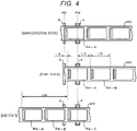
- FIG. 4 is a diagram illustrating state transition of the mount MO for calibration.
- FIG. 4 a state of the mount MO at a point in time when the forward-feed explained above is ended is illustrated on the upper side. That is, the leading end of one label paper RA indicated by a sign RA-A in FIG. 4 among the plurality of label papers RA is located in the detection position PD.
- the CPU 171 instructs the motor driving circuit 8 to convey the mount MO in the back direction by a first specified amount LA (hereinafter referred to as back-feed) .
- the motor driving circuit 8 rotates the motor 7 by a rotation amount corresponding to the first specified amount LA to back-feed the mount MO.
- the conveying roller 1 rotates counterclockwise with a rotational force of the motor 7 at this time and back-feeds the mount MO by the first specified amount LA.
- the first specified amount LA is calculated as a difference between an interval between the detection position PD and the center position PM and a half of the length of the label paper RA in the longitudinal direction.
- FIG. 4 a state of the mount MO at a point in time when the back-feed explained above is ended is illustrated in the center. This state is the start state.
- the CPU 171 instructs the motor driving circuit 8 to forward-feed the mount MO by a second specified amount.
- the motor driving circuit 8 rotates the motor 7 by a rotation amount corresponding to the second specified amount.
- the second specified amount is set to, for example, 1 cm.
- the second specified amount may be optionally set by, for example, a designer of the label printer 100.
- the CPU 171 acquires an RSSI and an identifier output from the reader writer 10 and saves the RSSI and the identifier in, for example, the internal memory of the main controller 17. At this time, the CPU 171 correlates a feed amount from the start state with the RSSI and the identifier. If a plurality of sets of RSSIs and identifiers are output from the reader writer 10, the CPU 171 acquires and saves all of the plurality of sets of RSSIs and identifiers.
- the CPU 171 confirms whether the calibration is in an end state.
- the end state is, for example, a state in which the feed amount from the start state is a third specified amount LB. It is assumed that the third specified amount LB is set to, for example, a double of the pitch PI. However, the third specified amount LB may be optionally set by, for example, the designer of the label printer 100.
- the CPU 171 determines NO and returns to ACT 13. That is, in a collection period from the start state to the end state, the CPU 171 collects an RSSI and an identifier every time the CPU 171 forward-feeds the mount MO by the second specified amount.
- the CPU 171 executes the information processing based on the information processing program in this way. Consequently, the computer including the CPU 171 as the central part functions as an acquiring unit.
- FIG. 4 a state of the mount MO at a point in time when the forward-feed explained above is ended is illustrated on the lower side. That is, the center of one label paper RA indicated by a sign RA-C in FIG. 4 among the plurality of label papers RA is located in the center position PM of the antenna 4.
- the label paper RA-C is the second label paper RA following a label paper RA-A. This state is the end state. If failing in confirming that the calibration is in such an end state, the CPU 171 determines YES in ACT 15 and proceeds to ACT 16.
- the line graphs of the RSSIs are line graphs formed by plotting the RSSIs with the vertical axis indicating the magnitude of an RSSI and the horizontal axis indicating a feed amount on the horizontal axis.
- FIG. 5 is a diagram illustrating line graphs of RSSIs concerning the wireless tags TA at the time when RSSIs concerning two wireless tags TA are successfully collected.
- the wireless tag TA concerning the line graph illustrated on the upper side is referred to as first wireless tag TA and the wireless tag TA concerning the line graph illustrated on the lower side is referred to as second wireless tag TA.
- the wireless tag TA attached to a label paper RA-B illustrated in FIG. 4 is the first wireless tag TA and the wireless tag TA attached to the label paper RA-C illustrated in FIG. 4 is the second wireless tag TA.
- the CPU 171 determines a feed amount FA as a feed amount equivalent to a position that bisects, at an area ratio, a hatching region illustrated on the upper side in the horizontal axis direction.
- the CPU 171 determines a feed amount FB as a feed amount equivalent to a position that bisects, at an area ratio, a hatching region illustrated on the lower side in the horizontal axis direction.
- the RSSI is acquired every time the mount MO is conveyed by the second specified amount, if the feed amount FA and the feed amount FB are values integer times as large as the second specified amount, the hatching region sometimes cannot be bisected at the area ratio in the horizontal axis direction. Therefore, in this case, a state in which the areas of respective two regions across the feed amount FA or the feed amount FB are the closest is regarded as the bisection.
- the area of a hatching region illustrated in FIG. 5 is proportional to a sum of electric field intensities illustrated in the hatching region. Therefore, a position that bisects the hatching region at an area ratio in the horizontal axis direction is an example of the intermediate position between the start position and the end position of the collection period.
- the position is a position where a sum of RSSIs collected while the mount MO is conveyed from the start position to the intermediate position and a sum of RSSIs collected while the mount MO is conveyed from the intermediate position to the end position are the closest.
- the CPU 171 executes the information processing based on the information processing program in this way. Consequently, the computer including the CPU 171 as the central part functions as a determining unit.
- the CPU 171 confirms whether a plurality of intermediate positions present in a prediction range are present in the intermediate position determined in ACT 16.
- the prediction range is a range from when the leading end of any label paper RA reaches the center position PM until when the trailing end of the label paper RA reaches the center position PM in the collection period.
- the center of the label paper RA-A is located in the center position PM of the antenna 4. If the forward-feed is performed from this state over a length LC calculated by subtracting a half of the length of the label paper RA in the conveying direction of the mount MO from the pitch PI, the leading end of the label paper RA immediately following the label paper RA-A reaches the center position PM.
- the label paper RA immediately following the label paper RA-A is illustrated with a sign RA-B in Fig. 4 . If the forward-feed is further performed over a length LD of the label paper RA in the longitudinal direction, the trailing end of the label paper RA-B reaches the center position PM. Therefore, the prediction range is a range in which the feed amount is the length LC to LC+LD.
- the feed amount FA is within the prediction range and the feed amount FB is not within the prediction range. Therefore, since only one intermediate position is located within the prediction range, the CPU 171 determines NO in ACT 17 in FIG. 3 and proceeds to ACT 18.
- the CPU 171 selects the wireless tag TA concerning the one intermediate position located in the prediction range as a calibration target wireless tag (hereinafter referred to as target tag) .
- target tag a calibration target wireless tag
- the CPU 171 selects the first wireless tag TA as the target tag.
- the CPU 171 determines YES in ACT 17 in FIG. 3 and proceeds to ACT 19.
- the CPU 171 selects, out of the plurality of intermediate positions located within the prediction range, an intermediate position having the smallest feed amount representing the intermediate position and selects the wireless tag TA concerning the intermediate position as the target tag. For example, if it is assumed that the feed amount FB illustrated in FIG. 5 is also within the prediction range, since the feed amount FA is smaller than the feed amount FB, the CPU 171 selects the first wireless tag TA corresponding to the feed amount FA as the target tag.
- the CPU 171 selects a wireless tag, an intermediate position of which is determined as a position within the prediction range, as the target tag.
- the CPU 171 executes the information processing based on the information processing program in this way. Consequently, the computer including the CPU 171 as the central part functions as a selecting unit.
- the CPU 171 decides, concerning the target tag, based on the RSSIs collected in ACT 12 and ACT 14, a relative positional relation between the target tag and the antenna 4 at the time when data is written in the target tag. For example, well-known processing can be directly used as this processing.
- the CPU 171 executes the information processing based on the information processing program in this way. Consequently, the computer including the CPU 171 as the central part functions as a deciding unit.
- the CPU 171 ends the information processing for the calibration.
- the wireless tag TA having a better communication condition is selected as the target tag out of the plurality of wireless tags TA present near the antenna 4 and, then, an optimum relative positional relation between the wireless tag and the antenna 4 is determined based on a communication state with the target tag. Therefore, the determination can be properly performed.
- FIG. 6 is a diagram illustrating the structure of a part of and a main part circuit configuration of a label printer 200 according to a second embodiment.
- the same components as the components illustrated in FIG. 1 are denoted by the same reference numerals and signs and detailed explanation of the components is omitted.
- a hardware configuration of the label printer 200 is different from the label printer 100 in that the hardware configuration of the label printer 200 further includes conveying rollers 21 and 22.
- the conveying rollers 21 and 22 are disposed to be opposed to each other in a state in which axes of both of the conveying rollers 21 and 22 are directed in the depth direction in FIG. 6 .
- the conveying rollers 21 and 22 hold the mount MO and convey the mount MO according to rotation around the axes. Both of the conveying rollers 21 and 22 are capable of rotating clockwise and counterclockwise in FIG. 6 and capable of conveying the mount MO in both of the forward direction and the back direction.
- the conveying roller 21 receives a rotational force of the motor 7 and rotates synchronously with the conveying roller 1.
- the rotational force generated by the motor 7 may be transmitted to the conveying roller 22 via a gear or the like to rotate the conveying roller 22.
- a function of a conveying unit that conveys a mount is realized by the conveying rollers 21 and 22 in addition to the conveying rollers 1 and 2, the motor 7, and the motor driving circuit 8.
- the label printer 200 is different from the label printer 100 in information processing executed by the CPU 171 for calibration.
- FIG. 7 is a flowchart of the information processing by the CPU 171 for the calibration.
- the CPU 171 starts forward-feed of the mount MO.
- the CPU 171 instructs the motor driving circuit 8 to start the forward-feed.
- the motor driving circuit 8 rotates the motor 7 to forward-feed the mount MO. If the motor 7 starts rotation, the conveying rollers 1 and 21 rotate clockwise with a rotational force of the rotation and forward-feed the mount MO.
- the CPU 171 waits for the mark MA to be detected. If the mark MA reaches the detection position PD and a change occurs in an output of the mark sensor 5, the sensor circuit 11 detects the mark MA in response to the change in the output. The sensor circuit 11 detects the mark MA in this way. According to the detection of the mark MA, the CPU 171 determines YES and proceeds to ACT 33.
- FIG. 8 is a diagram illustrating a state transition of the mount MO for calibration.
- FIG. 8 a state of the mount MO at a point in time when the mark MA is detected as explained above is illustrated on the upper side. That is, the leading end of one label paper RA indicated by a sign RA-B in FIG. 8 among a plurality of label papers RA is located in the detection position PD.
- the CPU 171 waits for the mount MO to be further forward-fed by a fourth specified amount LE.
- the fourth specified amount LE is set as an amount shorter than an interval between the detection position PD and the cut position PC, a sum of an interval between the label papers RA adjacent to each other and the fourth specified amount LE being larger than an interval between the detection position PD and the cut position PC.
- the fourth specified amount LE may be set as a value common to all types of label papers by, for example, a designer of the label printer 200.
- the fourth specified amount LE may be set by the CPU 171 according to a type of an attached label paper RA considering an interval between the label papers RA adjacent to each other.
- the CPU 171 may acquire an interval between the label papers RA for each type of the label paper RA according to, for example, an input of a value from the input unit 14 or may acquire the value by reading out a value correlated with a type of the label paper RA and described in a database set in a storage device provided on the inside or the outside of the label printer 200. If the mount MO is forward-fed by the fourth specified amount LE, the CPU 171 determines YES and proceeds to ACT 34.
- the CPU 171 stops the forward-feed of the mount MO.
- the CPU 171 instructs the motor driving circuit 8 to stop the motor 7.
- the motor driving circuit 8 stops the motor 7, whereby the forward-feed of the mount MO is stopped.
- FIG. 8 a state of the mount MO at a point in time when the forward-feed explained above is ended is illustrated in the center. As illustrated in FIG. 8 , a part between the label paper RA-B and the label paper RA-A preceding and adjacent to the label paper RA-B is located in the cut position PC.
- the CPU 171 cuts the mount MO.
- the CPU 171 instructs the cutter driving circuit 12 to cut the mount MO.
- the cutter driving circuit 12 drives the cutter 6.
- the cutter 6 cuts off a part of the mount MO located further on the downstream side in the forward direction than the cut position PC. Consequently, the label paper RA-A is cut off.
- the cut-off label paper RA-A is discharged to, for example, the outside of the label printer 200.
- the cutter 6 cuts the mount MO in a direction crossing the array direction of the wireless tags TA and is equivalent to a cutting unit.
- the CPU 171 forms a start state.
- the start state is, for example, a state in which an end portion of the mount MO formed anew by cutting off a part of the mount MO as explained above is aligned with the center position PM of the antenna 4.
- the CPU 171 instructs the motor driving circuit 8 to back-feed the mount MO by a fifth specified amount LF.
- the motor driving circuit 8 rotates the motor 7 by a rotation amount corresponding to the fifth specified amount LF to back-feed the mount MO.
- the conveying rollers 1 and 21 rotate counterclockwise with a rotational force of the motor 7 at this time and back-feed the mount MO by the fifth specified amount LF.
- the fifth specified amount LF is an interval between the cut position PC and the center position PM.
- FIG. 8 a state of the mount MO at a point in time when the back-feed explained above is ended is illustrated on the lower side. This state is the start state.
- the CPU 171 acquires an RSSI and an identifier output from the reader writer 10. If a plurality of sets of RSSIs and identifiers are output from the reader writer 10, the CPU 171 acquires all of the plurality of sets of RSSIs and identifiers. The CPU 171 executes the information processing based on the information processing program in this way. Consequently, a computer including the CPU 171 as a central part functions as an acquiring unit.
- the CPU 171 confirms whether a predetermined condition is satisfied concerning the RSSI acquired in ACT 37.
- the condition is determined in advance by, for example, the designer of the label printer 200 as a condition for determining whether the RSSI has magnitude enough for satisfactorily performing communication. As an example, the condition is "the RSSI is equal to or larger than a predetermined threshold". If failing in confirming that the condition is satisfied, the CPU 171 determines NO and proceeds to ACT 39.
- the CPU 171 instructs the motor driving circuit 8 to forward-feed the mount MO by a sixth specified amount.
- the motor driving circuit 8 rotates the motor 7 by a rotation amount corresponding to the sixth specified amount.
- the sixth specified amount is set to, for example, 1 cm.
- the sixth specified amount may be optionally set by, for example, the designer of the label printer 200.
- the CPU 171 controls a conveying unit configured by the conveying rollers 1 and 2, themotor 7, themotor driving circuit 8, and the conveying rollers 21 and 22 to convey the mount MO while causing the mount MO to pass a position opposed to the antenna 4. That is, the CPU 171 executes the information processing based on the information processing program. Consequently, the computer including the CPU 171 as the central part functions as a control unit.
- the CPU 171 acquires an RSSI and an identifier output from the reader writer 10. If a plurality of sets of RSSIs and identifiers are output from the reader writer 10, the CPU 171 acquires all of the plurality of sets of RSSIs and identifiers.
- ACT 41 as in ACT 38, the CPU 171 confirms whether the condition is satisfied. If failing in confirming that the condition is satisfied, the CPU 171 determines NO and returns to ACT 39. That is, the CPU 171 repeatedly acquires RSSIs while forward-feeding the mount MO by the sixth specified amount and waits for the condition to be satisfied concerning the RSSIs.
- the CPU 171 determines YES in ACT 38 or ACT 41 and proceeds to ACT 42.
- the CPU 171 selects, as a target tag, the wireless tag TA identified by an identifier acquired together with the RSSI concerning which the condition is satisfied.
- the CPU 171 executes the information processing based on the information processing program in this way. Consequently, the computer including the CPU 171 as the central part functions as a selecting unit.
- the CPU 171 collects RSSIs concerning the target tag while changing the position of the target tag and decides, based on the collected RSSIs, a relative positional relation between the target tag and the antenna 4 at the time when data is written in the target tag.
- This processing for example, well-known processing can be directly used.
- the RSSIs acquired in ACT 37 and ACT 40 may be saved.
- RSSI values other than the RSSIs may be collected.
- the CPU 171 executes the information processing based on the information processing program in this way. Consequently, the computer including the CPU 171 as the central part functions as a deciding unit.
- the CPU 171 ends the information processing for the calibration.
- the wireless tag TA having a better communication condition is selected as the target tag out of the plurality of wireless tags TA present near the antenna 4 and, then, an optimum relative positional relation between the wireless tag and the antenna 4 is determined based on a communication state with the target tag. Therefore, the determination can be properly performed.
- the processing for selecting the target tag is simpler compared with the label printer 100 and a load on the CPU 171 can be reduced.
- the conveying rollers 21 and 22 are provided because a back-feed amount for forming the start state is larger than the back-feed amount in the label printer 100. Therefore, a hardware configuration is more complicated than the label printer 100.
- the graph used for determining the intermediate position in the first embodiment may be a graph of another form such as a histogram if an area corresponding to the magnitude of an RSSI is generated.
- the determination of the intermediate position in the first embodiment can also be realized by an arithmetic operation in which a graph is not used.
- the first embodiment may be realized as a tag writing device that does not include a print function for printing on the label paper RA and writes data in the wireless tag TA.
- the reception intensity may be measured as an indicator value different from the RSSI.
Landscapes
- Engineering & Computer Science (AREA)
- General Physics & Mathematics (AREA)
- Physics & Mathematics (AREA)
- Theoretical Computer Science (AREA)
- General Engineering & Computer Science (AREA)
- Radar, Positioning & Navigation (AREA)
- Remote Sensing (AREA)
- Computer Networks & Wireless Communication (AREA)
- Microelectronics & Electronic Packaging (AREA)
- Computer Hardware Design (AREA)
- Accessory Devices And Overall Control Thereof (AREA)
- Printers Characterized By Their Purpose (AREA)
- Radar Systems Or Details Thereof (AREA)
Abstract
Description
- This application is based upon and claims the benefit of priority from
Japanese Patent Application No. P2020-200904, filed on December 3, 2020 - Embodiments described herein relate generally to a tag writing device, a label printer, and an information processing program.
- There has been known a label printer that performs printing on a label and writes information in a wireless tag attached to the label.
- In the label printer of this type, if labels of a plurality of types in which, for example, types of wireless tags are different or attached positions of wireless tags are different are made selectively usable, an optimum relationship between relative positions of a writing target wireless tag and an antenna sometimes changes depending on a type of a label to be used.
- Therefore, it is necessary to correctly perform calibration for determining an optimum relative positional relation between a wireless tag and an antenna concerning a set label.
- Under such circumstances, it has been desired to be able to properly determine an optimum relative positional relation between a wireless tag and an antenna.
- One of the objects of the present invention is to improve prior art techniques and overcome at least some of the prior art problems as for instance above illustrated.
- According to a first aspect of the present invention, it is provided a tag writing device, comprising a conveying component configured to convey a mount, to which a plurality of wireless tags are attached in a row at about equal intervals, along an array direction of the plurality of wireless tags; an antenna opposed to the mount conveyed by the conveying component, the antenna being provided for wireless communication with a plurality of wireless tags located within a communication range among the plurality of wireless tags; an acquiring component configured to acquire, in a period in which the mount is conveyed by the conveying component from a predetermined start position to a predetermined end position, a plurality of times each time the mount is conveyed by the conveying component by a fixed amount, reception intensities in the antenna of radio signals transmitted from the plurality of wireless tags; a determining component configured to determine, concerning each of the plurality of wireless tags, an intermediate position between the start position and the end position as a position where a sum of reception intensities acquired by the acquiring component while the mount is conveyed from the start position to the intermediate position by the conveying component and a sum of reception intensities acquired by the acquiring component while the mount is conveyed from the intermediate position to the end position by the conveying component are closest; a selecting component configured to select, as a target tag, the wireless tag, the intermediate position of which is determined by the determining component as a position within a prediction range predetermined as a range included in a range between the start position and the end position; and a deciding component configured to decide, based on reception intensity in the antenna of a radio signal transmitted from the target tag selected by the selecting component, a relative positional relation between the wireless tag and the antenna at a time when writing is performed in one of the plurality of wireless tags.
- Optionally, in the tag writing device according to the first aspect of the invention, the determining component determines the intermediate position by an arithmetic operation.
- Optionally, in the tag writing device according to the first aspect of the invention, the plurality of wireless tags are attached in at about 1 cm intervals.
- Optionally, in the tag writing device according to the first aspect of the invention, the plurality of wireless tags are radio frequency identification wireless tags.
- According to a second aspect of the invention, it is provided a label printer, comprising a conveying component configured to convey a mount, to which a plurality of label papers respectively attached with wireless tags are stuck in a row at about equal intervals, along an array direction of the plurality of label papers; a print component configured to print an image on the label paper; an antenna opposed to the mount conveyed by the conveying component, the antenna being provided for wireless communication with a plurality of wireless tags located within a communication range among the plurality of wireless tags; an acquiring component configured to acquire, in a period in which the mount is conveyed by the conveying component from a predetermined start position to a predetermined end position, a plurality of times each time the mount is conveyed by the conveying component by a fixed amount, reception intensities in the antenna of radio signals transmitted from the plurality of wireless tags; a determining component configured to determine, concerning each of the plurality of wireless tags, an intermediate position between the start position and the end position as a position where a sum of reception intensities acquired by the acquiring component while the mount is conveyed from the start position to the intermediate position by the conveying component and a sum of reception intensities acquired by the acquiring component while the mount is conveyed from the intermediate position to the end position by the conveying component are closest; a selecting component configured to select, as a target tag, the wireless tag, the intermediate position of which is determined by the determining component as a position within a prediction range predetermined as a range included in a range between the start position and the end position; a deciding component configured to decide, based on reception intensity in the antenna of a radio signal transmitted from the target tag selected by the selecting component, a relative positional relation between the wireless tag and the antenna at a time when writing is performed in one of the plurality of wireless tags; and a transmitting component configured to, if a relative positional relation between a wireless tag, which is one of the plurality of wireless tags, and the antenna is the positional relation decided by the deciding component, cause the antenna to transmit a radio wave for writing data in the wireless tag.
- Optionally, in the label printer according to the second aspect of the invention, the determining component determines the intermediate position by an arithmetic operation.
- Optionally, in the label printer according to the second aspect of the invention, the plurality of wireless tags are attached in at about 1 cm intervals.
- Optionally, in the label printer according to the second aspect of the invention, the plurality of wireless tags are radio frequency identification wireless tags.
- Optionally, in the label printer according to the second aspect of the invention, the print component is a thermal-type print head.
- According to a third aspect of the invention, it is provided an information processing method for a tag writing device, comprising acquiring, in a period in which a mount, to which a plurality of wireless tags are attached in a row at equal intervals, along an array direction of the plurality of wireless tags, is conveyed by a conveying component from a predetermined start position to a predetermined end position, a plurality of times each time the mount is conveyed by the conveying component by a fixed amount, reception intensities in an antenna of radio signals transmitted from the plurality of wireless tags, the antenna being provided for wireless communication with a plurality of wireless tags located within a communication range among the plurality of wireless tags; determining, concerning each of the plurality of wireless tags, an intermediate position between the start position and the end position as a position where a sum of reception intensities acquired while the mount is conveyed from the start position to the intermediate position by the conveying component and a sum of reception intensities acquired while the mount is conveyed from the intermediate position to the end position by the conveying component are closest; selecting, as a target tag, the wireless tag, the intermediate position of which is determined as a position within a prediction range predetermined as a range included in a range between the start position and the end position; and deciding, based on reception intensity in the antenna of a radio signal transmitted from the selected target tag, a relative positional relation between the wireless tag and the antenna at a time when writing is performed in one of the plurality of wireless tags.
- According to a fourth aspect of the invention, it is provided a tag writing device, comprising: a conveying component configured to convey a mount, to which a plurality of wireless tags are attached in a row at about equal intervals, along an array direction of the plurality of wireless tags; an antenna opposed to the mount conveyed by the conveying component, the antenna being provided for wireless communication with one or a plurality of wireless tags located within a communication range among the plurality of wireless tags; a cutting component configured to cut the mount in a direction crossing the array direction; a controller configured to set an end portion of the mount formed by being cut by the cutting unit to be opposed to the antenna and, thereafter, control the conveying component to convey the mount while causing the mount to pass a position opposed to the antenna; an acquiring component configured to, if the mount is conveyed by the conveying component while passing the position opposed to the antenna, acquire, a plurality of times, reception intensities in the antenna of radio signals transmitted from the plurality of wireless tags; a selecting component configured to, if reception intensity matching a predetermined condition is acquired by the acquiring component, select, as a target tag, one wireless tag that transmits a radio signal for generating the reception intensity in the antenna among the plurality of wireless tags; and a deciding component configured to decide, based on reception intensity in the antenna of a radio signal transmitted from the target tag selected by the selecting component, a relative positional relation between the wireless tag and the antenna at a time when writing is performed in one of the plurality of wireless tags.
- Optionally, in the tag writing device according to the fourth aspect of the invention, the determining component determines the intermediate position by an arithmetic operation.
- Optionally, in the tag writing device according to the fourth aspect of the invention, the plurality of wireless tags are attached in at about 1 cm intervals.
- Optionally, in the tag writing device according to the fourth aspect of the invention, the plurality of wireless tags are radio frequency identification wireless tags.
- According to a fifth aspect of the invention, it is provided a label printer, comprising: a conveying component configured to convey a mount, to which a plurality of label papers respectively attached with wireless tags are stuck in a row at about equal intervals, along an array direction of the plurality of label papers; a print component configured to print an image on the label paper; an antenna opposed to the mount conveyed by the conveying component, the antenna being provided for wireless communication with one or a plurality of wireless tags located within a communication range among the plurality of wireless tags; a cutting component configured to cut the mount in a direction crossing the array direction; a controller configured to set an end portion of the mount formed by being cut by the cutting component to be opposed to the antenna and, thereafter, control the conveying unit to convey the mount while causing the mount to pass a position opposed to the antenna; an acquiring component configured to, if the mount is conveyed by the conveying component while being caused to pass the position opposed to the antenna, acquire, a plurality of times, reception intensities in the antenna of radio signals transmitted from the plurality of wireless tags; a selecting component configured to, if reception intensity matching a predetermined condition is acquired by the acquiring component, select, as a target tag, one wireless tag that transmits a radio signal for generating the reception intensity in the antenna among the plurality of wireless tags; a deciding component configured to decide, based on reception intensity in the antenna of a radio signal transmitted from the target tag selected by the selecting component, a relative positional relation between the wireless tag and the antenna at a time when writing is performed in one of the plurality of wireless tags; and a transmitting component configured to, if a relative positional relation between a wireless tag, which is one of the plurality of wireless tags, and the antenna is the positional relation decided by the deciding component, cause the antenna to transmit a radio wave for writing data in the wireless tag.
- Optionally, in the label printer according to the fifth aspect of the invention, the determining component determines the intermediate position by an arithmetic operation.
- Optionally, in the label printer according to the fifth aspect of the invention, the plurality of wireless tags are attached in at about 1 cm intervals.
- Optionally, in the label printer according to the fifth aspect of the invention, the plurality of wireless tags are radio frequency identification wireless tags.
- Optionally, in the label printer according to the fifth aspect of the invention, the print component is a thermal-type print head.
- According to a sixth aspect, it is provided an information processing method for a tag writing device, comprising:
- setting an end portion of a mount, to which a plurality of wireless tags are attached in a row at equal intervals, along an array direction of the plurality of wireless tags, formed by being cut by a cutting component, the configured to cut the mount in a direction crossing the array direction, opposed to the antenna and, thereafter, controlling the conveying component to convey the mount while causing the mount to pass a position opposed to an antenna, the antenna being provided for wireless communication with one or a plurality of wireless tags located within a communication range among the plurality of wireless tags;
- if the mount is conveyed by the conveying component while passing the position opposed to the antenna, acquiring, a plurality of times, reception intensities in the antenna of radio signals transmitted from the plurality of wireless tags;
- if reception intensity matching a predetermined condition is acquired, selecting, as a target tag, one wireless tag that transmits a radio signal for generating the reception intensity in the antenna among the plurality of wireless tags; and
- deciding, based on reception intensity in the antenna of a radio signal transmitted from the selected target tag, a relative positional relation between the wireless tag and the antenna at a time when writing is performed in one of the plurality of wireless tags.
-
-
FIG. 1 is a diagram illustrating the structure of a part of and a main part circuit configuration of a label printer according to a first embodiment; -
FIG. 2 is a diagram illustrating exteriors of a front surface and a rear surface of a mount; -
FIG. 3 is a flowchart of information processing by a CPU inFIG. 1 for calibration; -
FIG. 4 is a diagram illustrating a transition state of a mount for calibration in the first embodiment; -
FIG. 5 is a diagram illustrating line graphs of RSSIs concerning two wireless tags; -
FIG. 6 is a diagram illustrating the structure of a part of and a main part circuit configuration of a label printer according to a second embodiment; -
FIG. 7 is a flowchart of information processing by a CPU inFIG. 6 for calibration; and -
FIG. 8 is a diagram illustrating a state transition of a mount for calibration in the second embodiment. - An aspect of embodiments is to provide, in order to solve the problems described above, a tag writing device, a label printer, and an information processing program that can correctly perform calibration for determining an optimum relative positional relation between a wireless tag and an antenna.
- A tag writing device according to an embodiment includes a conveying unit, an antenna, an acquiring unit, a determining unit, a selecting unit, and a deciding unit. The conveying unit conveys a mount, to which a plurality of wireless tags are attached in a row at equal intervals, along an array direction of the plurality of wireless tags. The antenna is disposed to be opposed to the mount conveyed by the conveying unit and is provided for wireless communication with a plurality of wireless tags located within a communication range among the plurality of wireless tags. The acquiring unit acquires, in a period in which the mount is conveyed by the conveying unit from a predetermined start position to a predetermined end position, a plurality of times every time the mount is conveyed by the conveying unit by a fixed amount, reception intensities in the antenna of radio signals transmitted from the plurality of wireless tags. The determining unit determines, concerning each of the plurality of wireless tags, an intermediate position between the start position and the end position as a position where a sum of reception intensities acquired by the acquiring unit while the mount is conveyed from the start position to the intermediate position by the conveying unit and a sum of reception intensities acquired by the acquiring unit while the mount is conveyed from the intermediate position to the end position by the conveying unit are closest. The selecting unit selects, as a target tag, the wireless tag, the intermediate position of which is determined by the determining unit as a position within a prediction range predetermined as a range included in a range between the start position and the end position. The deciding unit decides, based on reception intensity in the antenna of a radio signal transmitted from the target tag selected by the selecting unit, a relative positional relation between the wireless tag and the antenna at a time when writing is performed in one of the plurality of wireless tags.
- Embodiments are explained below with reference to the drawings.
-
FIG. 1 is a diagram illustrating the structure of a part of and a main part circuit configuration of alabel printer 100 according to a first embodiment. - The label printer 100 prints, while conveying an elongated mount MO, an image representing characters and the like on label paper RA stuck to one surface (hereinafter referred to as front surface) of the mount MO. The
label printer 100 writes data in a wireless tag attached to the label paper RA. The material of the mount MO and the label paper RA is typically paper but may be a material other than the paper such as resin. The materials of the mount MO and the label paper RA may be different from each other. In this embodiment, the label paper RA is heat-sensitive paper. As the wireless tag, for example, an RFID (radio frequency identifier) tag can be used. -
FIG. 2 is a diagram illustrating the exteriors of a front surface and a rear surface of the mount MO. - A plurality of label papers RA are stuck to the front surface of the mount MO in a row at equal intervals along the longitudinal direction of the mount MO. That is, the plurality of label papers RA are arranged on the front surface of the mount MO in a row at a pitch PI. In the following explanation, the longitudinal direction of the mount MO is simply referred to as "longitudinal direction". A wireless tag TA is attached to each of the label papers RA. In this embodiment, an attached position of the wireless tag TA in the label paper RA is near one end portion of the label paper RA. However, the attached position of the wireless tag TA in the label paper RA is not limited to this.
- On the rear surface of the mount MO, a mark MA is formed in a position corresponding to an end portion on a downstream side in a feed direction among end portions of the label paper RA. In this embodiment, the mark MA is a straight line in a direction crossing the longitudinal direction. However, the mark MA may be any form if the mark MA represents the position of the end portion.
- The
label printer 100 includes conveyingrollers print head 3, anantenna 4, amark sensor 5, acutter 6, amotor 7, amotor driving circuit 8, ahead driving circuit 9, areader writer 10, asensor circuit 11, acutter driving circuit 12, adisplay unit 13, aninput unit 14, amemory 15, aninterface unit 16, and amain controller 17. - Both of the conveying
rollers FIG. 1 . The conveyingrollers rollers FIG. 1 and capable of conveying the mount MO in both of a direction toward the left side inFIG. 1 (hereinafter referred to as forward direction) and a direction toward the right side inFIG. 1 (hereinafter referred to as back direction). - The
print head 3 is disposed to be opposed to the front surface side of the mount MO conveyed by the conveyingrollers print head 3 prints an image on the label paper RA is a position further on an upstream side in the forward direction than a position where the mount MO is held by the conveyingrollers print head 3 is a thermal-type print head. However, theprint head 3 can be replaced with devices of a thermal transfer type, a dot impact type, an inkjet type, and other various types. - The
antenna 4 is disposed to be opposed to the rear surface side of the mount MO conveyed by the conveyingrollers antenna 4 may be disposed to be opposed to the front surface side of the mount MO. Theantenna 4 radiates a radio wave to be received by a wireless tag attached to the label paper RA to the wireless tag. Theantenna 4 receives a radio wave radiated from the wireless tag attached to the label paper RA and generates an electric signal corresponding to the radio wave. A center position PM of theantenna 4 along a conveying direction of the mount MO is further on the upstream in the forward direction than the print position PP. - The
mark sensor 5 is disposed to be opposed to the rear surface side of the mount MO conveyed by the conveyingrollers mark sensor 5 detects the mark MA formed on the rear surface of the mount MO. A detection position PD of the mark MA by themark sensor 5 is a position between the position where the mount MO is held by the conveyingrollers - The
cutter 6 cuts the mount MO. A cut position PC where thecutter 6 cuts the mount MO is a position further on the downstream side in the forward direction than the position where the mount MO is held by the conveyingrollers - The
motor 7 generates a rotational force. The rotational force generated by themotor 7 is transmitted to the conveyingroller 1 via a gear or the like to rotate the conveyingroller 1. The rotational force generated by themotor 7 may be transmitted to the conveyingroller 2 via a gear or the like to rotate the conveyingroller 2. - The
motor driving circuit 8 drives, under control by themain controller 17, themotor 7 to generate a required rotational force. - The
head driving circuit 9 drives, under the control by themain controller 17, theprint head 3 to print any image on the label paper RA. - The
reader writer 10 extracts, from an electric signal obtained by theantenna 4 according to a radio wave radiated from the wireless tag TA, response data transmitted by the wireless tag TA. Thereader writer 10 supplies, to theantenna 4, a transmission signal for wirelessly transmitting data to be written in the wireless tag TA to the wireless tag TA. Thereader writer 10 has a function of, in a situation in which a radio wave transmitted from the wireless tag TA is received by theantenna 4, measuring reception intensity of the radio wave. In this embodiment, reception electric field intensity (receive signal strength indicator: RSSI) is used as the reception intensity. Thereader writer 10 outputs a measured RSSI together with an identifier for identifying the wireless tag TA that transmits a radio wave concerning the RSSI. In a situation in which radio waves respectively transmitted from a plurality of wireless tags TA are received by theantenna 4, thereader writer 10 measures an RSSI of each of the radio waves and outputs the RSSI together with an identifier for identifying the individual wireless tag TA. - The
sensor circuit 11 detects based on an output signal of themark sensor 5 that the mark MA reaches the detection position PD. - The
cutter driving circuit 12 drives, under the control by themain controller 17, thecutter 6 to cut the mount MO. - The
display unit 13 performs various display operations for notifying various kinds of information to an operator. As thedisplay unit 13, well-known display devices such as a screen display device such as a liquid crystal display and a light emitting device such as an LED lamp can be used alone or in combination. - Various instructions by the operator are input to the
input unit 14. As theinput unit 14, well-known input devices such as a touch sensor, a key switch, and a keyboard can be used alone or in combination. - As the
display unit 13 and theinput unit 14, a single touch panel may be used. - The
memory 15 saves data concerning an image to be printed on the label paper RA or data to be written in the wireless tag TA. - The
interface unit 16 performs communication processing for exchanging data with an external information terminal device or the like. As theinterface unit 16, for example, a well-known communication device conforming to the LAN (local area network) standard can be used. - The
main controller 17 includes aCPU 171. Themain controller 17 controls, according to information processing by theCPU 171, in order to realize operation of thelabel printer 100, the units such as themotor driving circuit 8, thehead driving circuit 9, thereader writer 10, thesensor circuit 11, thecutter driving circuit 12, thedisplay unit 13, theinput unit 14, thememory 15, and theinterface unit 16. As themain controller 17, for example, a microcomputer including, besides theCPU 171, a memory for storing an information processing program, which describes information processing by theCPU 171, and to be used by theCPU 171 as a work area can be used. - The operation of the
label printer 100 configured as explained above is explained. Content of processing explained below is an example . A change of order of a part of the processing, omission of a part of the processing, addition of other processing, or the like is possible as appropriate. - The
label printer 100 is used to, for example, issue labels stuck to commodities displayed and sold in a store. In the case of this use, thelabel printer 100 writes, in the wireless tag TA, tag data for causing a POS terminal or the like to capture a sales price and the like and prints an image representing the sales price and the like on the label paper RA to which the wireless tag TA is stuck. If a relative positional relation between the writing target wireless tag TA and theantenna 4 is in a state in which communication with the writing target wireless tag can be satisfactorily performed, the writing of the tag data in the wireless tag TA is performed by thereader writer 10 transmitting a radio signal for writing via theantenna 4 under control by theCPU 171. That is, a function of a transmitting unit is realized by cooperation of a computer including theCPU 171 as a central part and thereader writer 10. The print of the image on the label paper RA is performed by the drivingcircuit 9 driving theprint head 3 under the control by theCPU 171. That is, a function of a print unit is realized by theprint head 3 and thehead driving circuit 9. - The
label printer 100 allows a plurality of types of label papers RA to be selectively attached. The pitch PI, the length of the label paper RA in the longitudinal direction, an attached position of the wireless tag TA in the label paper RA, a wireless communication characteristic of the wireless tag TA, or the like is sometimes different depending on a type of the label paper RA. Consequently, a relative positional relation between the label paper RA and theantenna 4 suitable for writing data in the wireless tag TA is sometimes different depending on the type of the label paper RA. Therefore, calibration for determining the relative positional relation between the label paper RA and theantenna 4 suitable for writing data in the wireless tag TA is executed if a type of the label paper RA to be attached is changed. A characteristic operation in this embodiment is operation concerning the calibration. Therefore, the operation is explained below. - If a predetermined execution condition is satisfied, the
CPU 171 starts information processing for the calibration. -
FIG. 3 is a flowchart of the information processing by theCPU 171 for the calibration. - In
ACT 11, theCPU 171 forms a start state of the calibration. The start state is, for example, a state in which the center of the label paper RA is aligned with the center position PM of theantenna 4. For example, theCPU 171 instructs themotor driving circuit 8 to start conveyance of the mount MO in the forward direction (hereinafter referred to a forward feed). According to the instruction, themotor driving circuit 8 rotates themotor 7 to forward-feed the mount MO. If themotor 7 starts rotation, the conveyingroller 1 rotates clockwise with a rotational force of the rotation and forward-feeds the mount MO. In this way, a function of a conveying unit that conveys a mount is realized by the conveyingrollers motor 7, and themotor driving circuit 8. If the mark MA reaches the detection position PD, a change occurs in an output of themark sensor 5. Thesensor circuit 11 detects the mark MA in response to the change in the output. TheCPU 171 instructs themotor driving circuit 8 to stop according to the detection of the mark MA by thesensor circuit 11. Themotor driving circuit 8 stops themotor 7 according to the instruction, whereby the mark MA on the mount MO is located in the detection position PD. -
FIG. 4 is a diagram illustrating state transition of the mount MO for calibration. - In
FIG. 4 , a state of the mount MO at a point in time when the forward-feed explained above is ended is illustrated on the upper side. That is, the leading end of one label paper RA indicated by a sign RA-A inFIG. 4 among the plurality of label papers RA is located in the detection position PD. - Subsequently, the
CPU 171 instructs themotor driving circuit 8 to convey the mount MO in the back direction by a first specified amount LA (hereinafter referred to as back-feed) . According to the instruction, themotor driving circuit 8 rotates themotor 7 by a rotation amount corresponding to the first specified amount LA to back-feed the mount MO. The conveyingroller 1 rotates counterclockwise with a rotational force of themotor 7 at this time and back-feeds the mount MO by the first specified amount LA. The first specified amount LA is calculated as a difference between an interval between the detection position PD and the center position PM and a half of the length of the label paper RA in the longitudinal direction. - In
FIG. 4 , a state of the mount MO at a point in time when the back-feed explained above is ended is illustrated in the center. This state is the start state. - In
ACT 12, theCPU 171 acquires an RSSI and an identifier output from thereader writer 10 and saves the RSSI and the identifier in, for example, an internal memory of themain controller 17. At this time, theCPU 171 corelates a feed amount=0 with the RSSI and the identifier. If a plurality of sets of RSSIs and identifiers are output from thereader writer 10, theCPU 171 acquires and saves all of the plurality of sets of RSSIs and identifiers. - In
ACT 13, theCPU 171 instructs themotor driving circuit 8 to forward-feed the mount MO by a second specified amount. According to the instruction, themotor driving circuit 8 rotates themotor 7 by a rotation amount corresponding to the second specified amount. It is assumed that the second specified amount is set to, for example, 1 cm. However, the second specified amount may be optionally set by, for example, a designer of thelabel printer 100. - In
ACT 14, theCPU 171 acquires an RSSI and an identifier output from thereader writer 10 and saves the RSSI and the identifier in, for example, the internal memory of themain controller 17. At this time, theCPU 171 correlates a feed amount from the start state with the RSSI and the identifier. If a plurality of sets of RSSIs and identifiers are output from thereader writer 10, theCPU 171 acquires and saves all of the plurality of sets of RSSIs and identifiers. - In
ACT 15, theCPU 171 confirms whether the calibration is in an end state. The end state is, for example, a state in which the feed amount from the start state is a third specified amount LB. It is assumed that the third specified amount LB is set to, for example, a double of the pitch PI. However, the third specified amount LB may be optionally set by, for example, the designer of thelabel printer 100. If failing in confirming that the calibration is in the end state, theCPU 171 determines NO and returns toACT 13. That is, in a collection period from the start state to the end state, theCPU 171 collects an RSSI and an identifier every time theCPU 171 forward-feeds the mount MO by the second specified amount. TheCPU 171 executes the information processing based on the information processing program in this way. Consequently, the computer including theCPU 171 as the central part functions as an acquiring unit. - In
FIG. 4 , a state of the mount MO at a point in time when the forward-feed explained above is ended is illustrated on the lower side. That is, the center of one label paper RA indicated by a sign RA-C inFIG. 4 among the plurality of label papers RA is located in the center position PM of theantenna 4. The label paper RA-C is the second label paper RA following a label paper RA-A. This state is the end state. If failing in confirming that the calibration is in such an end state, theCPU 171 determines YES inACT 15 and proceeds toACT 16. - In
ACT 16, theCPU 171 determines, considering the RSSI acquired inACT 12 and the RSSIs collected by repeatingACT 14, an intermediate position between a position of the mount MO in the start state and a position of the mount MO in the end state. For example, theCPU 171 determines the intermediate position as a position that bisects, at an area ratio, in a horizontal axis direction, a polygon formed between line graphs of a plurality of RSSIs and the horizontal axis of RSSI=0 acquired, concerning each of identifiers acquired in the collection period, together with the identifier. For example, theCPU 171 determines a feed amount equivalent to the intermediate position as an indicator value of the intermediate position. The line graphs of the RSSIs are line graphs formed by plotting the RSSIs with the vertical axis indicating the magnitude of an RSSI and the horizontal axis indicating a feed amount on the horizontal axis. -
FIG. 5 is a diagram illustrating line graphs of RSSIs concerning the wireless tags TA at the time when RSSIs concerning two wireless tags TA are successfully collected. - In the following explanation concerning
FIG. 5 , the wireless tag TA concerning the line graph illustrated on the upper side is referred to as first wireless tag TA and the wireless tag TA concerning the line graph illustrated on the lower side is referred to as second wireless tag TA. As an example, the wireless tag TA attached to a label paper RA-B illustrated inFIG. 4 is the first wireless tag TA and the wireless tag TA attached to the label paper RA-C illustrated inFIG. 4 is the second wireless tag TA. - Concerning the first wireless tag TA, the
CPU 171 determines a feed amount FA as a feed amount equivalent to a position that bisects, at an area ratio, a hatching region illustrated on the upper side in the horizontal axis direction. Concerning the second wireless tag TA, theCPU 171 determines a feed amount FB as a feed amount equivalent to a position that bisects, at an area ratio, a hatching region illustrated on the lower side in the horizontal axis direction. However, since the RSSI is acquired every time the mount MO is conveyed by the second specified amount, if the feed amount FA and the feed amount FB are values integer times as large as the second specified amount, the hatching region sometimes cannot be bisected at the area ratio in the horizontal axis direction. Therefore, in this case, a state in which the areas of respective two regions across the feed amount FA or the feed amount FB are the closest is regarded as the bisection. - The area of a hatching region illustrated in
FIG. 5 is proportional to a sum of electric field intensities illustrated in the hatching region. Therefore, a position that bisects the hatching region at an area ratio in the horizontal axis direction is an example of the intermediate position between the start position and the end position of the collection period. The position is a position where a sum of RSSIs collected while the mount MO is conveyed from the start position to the intermediate position and a sum of RSSIs collected while the mount MO is conveyed from the intermediate position to the end position are the closest. TheCPU 171 executes the information processing based on the information processing program in this way. Consequently, the computer including theCPU 171 as the central part functions as a determining unit. - In
ACT 17, theCPU 171 confirms whether a plurality of intermediate positions present in a prediction range are present in the intermediate position determined inACT 16. The prediction range is a range from when the leading end of any label paper RA reaches the center position PM until when the trailing end of the label paper RA reaches the center position PM in the collection period. - As explained above and illustrated in
FIG. 4 , in the start state, the center of the label paper RA-A is located in the center position PM of theantenna 4. If the forward-feed is performed from this state over a length LC calculated by subtracting a half of the length of the label paper RA in the conveying direction of the mount MO from the pitch PI, the leading end of the label paper RA immediately following the label paper RA-A reaches the center position PM. The label paper RA immediately following the label paper RA-A is illustrated with a sign RA-B inFig. 4 . If the forward-feed is further performed over a length LD of the label paper RA in the longitudinal direction, the trailing end of the label paper RA-B reaches the center position PM. Therefore, the prediction range is a range in which the feed amount is the length LC to LC+LD. - In an example illustrated in
FIG. 5 , the feed amount FA is within the prediction range and the feed amount FB is not within the prediction range. Therefore, since only one intermediate position is located within the prediction range, theCPU 171 determines NO inACT 17 inFIG. 3 and proceeds to ACT 18. - In ACT 18, the
CPU 171 selects the wireless tag TA concerning the one intermediate position located in the prediction range as a calibration target wireless tag (hereinafter referred to as target tag) . For example, in the example illustrated inFIG. 5 , theCPU 171 selects the first wireless tag TA as the target tag. - On the other hand, if a plurality of intermediate positions are located within the prediction range, the
CPU 171 determines YES inACT 17 inFIG. 3 and proceeds to ACT 19. - In ACT 19, the
CPU 171 selects, out of the plurality of intermediate positions located within the prediction range, an intermediate position having the smallest feed amount representing the intermediate position and selects the wireless tag TA concerning the intermediate position as the target tag. For example, if it is assumed that the feed amount FB illustrated inFIG. 5 is also within the prediction range, since the feed amount FA is smaller than the feed amount FB, theCPU 171 selects the first wireless tag TA corresponding to the feed amount FA as the target tag. - As explained above, the
CPU 171 selects a wireless tag, an intermediate position of which is determined as a position within the prediction range, as the target tag. TheCPU 171 executes the information processing based on the information processing program in this way. Consequently, the computer including theCPU 171 as the central part functions as a selecting unit. - If the
CPU 171 selects the target tag in ACT 18 or ACT 19 inFIG. 3 , theCPU 171 proceeds to ACT 20. - In ACT 20, the
CPU 171 decides, concerning the target tag, based on the RSSIs collected inACT 12 andACT 14, a relative positional relation between the target tag and theantenna 4 at the time when data is written in the target tag. For example, well-known processing can be directly used as this processing. TheCPU 171 executes the information processing based on the information processing program in this way. Consequently, the computer including theCPU 171 as the central part functions as a deciding unit. - Thereafter, the
CPU 171 ends the information processing for the calibration. - As explained above, with the
label printer 100, based on the collected RSSIs, the wireless tag TA having a better communication condition is selected as the target tag out of the plurality of wireless tags TA present near theantenna 4 and, then, an optimum relative positional relation between the wireless tag and theantenna 4 is determined based on a communication state with the target tag. Therefore, the determination can be properly performed. -
FIG. 6 is a diagram illustrating the structure of a part of and a main part circuit configuration of alabel printer 200 according to a second embodiment. InFIG. 6 , the same components as the components illustrated inFIG. 1 are denoted by the same reference numerals and signs and detailed explanation of the components is omitted. - A hardware configuration of the
label printer 200 is different from thelabel printer 100 in that the hardware configuration of thelabel printer 200 further includes conveyingrollers - The conveying
rollers rollers FIG. 6 . The conveyingrollers rollers FIG. 6 and capable of conveying the mount MO in both of the forward direction and the back direction. The conveyingroller 21 receives a rotational force of themotor 7 and rotates synchronously with the conveyingroller 1. The rotational force generated by themotor 7 may be transmitted to the conveyingroller 22 via a gear or the like to rotate the conveyingroller 22. In this way, in thelabel printer 200, a function of a conveying unit that conveys a mount is realized by the conveyingrollers rollers motor 7, and themotor driving circuit 8. - The
label printer 200 is different from thelabel printer 100 in information processing executed by theCPU 171 for calibration. -
FIG. 7 is a flowchart of the information processing by theCPU 171 for the calibration. - In ACT 31, the
CPU 171 starts forward-feed of the mount MO. For example, theCPU 171 instructs themotor driving circuit 8 to start the forward-feed. According to the instruction, themotor driving circuit 8 rotates themotor 7 to forward-feed the mount MO. If themotor 7 starts rotation, the conveyingrollers - In ACT 32, the
CPU 171 waits for the mark MA to be detected. If the mark MA reaches the detection position PD and a change occurs in an output of themark sensor 5, thesensor circuit 11 detects the mark MA in response to the change in the output. Thesensor circuit 11 detects the mark MA in this way. According to the detection of the mark MA, theCPU 171 determines YES and proceeds to ACT 33. -
FIG. 8 is a diagram illustrating a state transition of the mount MO for calibration. - In
FIG. 8 , a state of the mount MO at a point in time when the mark MA is detected as explained above is illustrated on the upper side. That is, the leading end of one label paper RA indicated by a sign RA-B inFIG. 8 among a plurality of label papers RA is located in the detection position PD. - In ACT 33, after the mark MA is detected, the
CPU 171 waits for the mount MO to be further forward-fed by a fourth specified amount LE. The fourth specified amount LE is set as an amount shorter than an interval between the detection position PD and the cut position PC, a sum of an interval between the label papers RA adjacent to each other and the fourth specified amount LE being larger than an interval between the detection position PD and the cut position PC. The fourth specified amount LE may be set as a value common to all types of label papers by, for example, a designer of thelabel printer 200. Alternatively, the fourth specified amount LE may be set by theCPU 171 according to a type of an attached label paper RA considering an interval between the label papers RA adjacent to each other. TheCPU 171 may acquire an interval between the label papers RA for each type of the label paper RA according to, for example, an input of a value from theinput unit 14 or may acquire the value by reading out a value correlated with a type of the label paper RA and described in a database set in a storage device provided on the inside or the outside of thelabel printer 200. If the mount MO is forward-fed by the fourth specified amount LE, theCPU 171 determines YES and proceeds to ACT 34. - In ACT 34, the
CPU 171 stops the forward-feed of the mount MO. For example, theCPU 171 instructs themotor driving circuit 8 to stop themotor 7. According to the instruction, themotor driving circuit 8 stops themotor 7, whereby the forward-feed of the mount MO is stopped. - In
FIG. 8 , a state of the mount MO at a point in time when the forward-feed explained above is ended is illustrated in the center. As illustrated inFIG. 8 , a part between the label paper RA-B and the label paper RA-A preceding and adjacent to the label paper RA-B is located in the cut position PC. - In ACT 35, the
CPU 171 cuts the mount MO. For example, theCPU 171 instructs thecutter driving circuit 12 to cut the mount MO. According to the instruction, thecutter driving circuit 12 drives thecutter 6. Thecutter 6 cuts off a part of the mount MO located further on the downstream side in the forward direction than the cut position PC. Consequently, the label paper RA-A is cut off. The cut-off label paper RA-A is discharged to, for example, the outside of thelabel printer 200. Thecutter 6 cuts the mount MO in a direction crossing the array direction of the wireless tags TA and is equivalent to a cutting unit. - In ACT 36, the
CPU 171 forms a start state. The start state is, for example, a state in which an end portion of the mount MO formed anew by cutting off a part of the mount MO as explained above is aligned with the center position PM of theantenna 4. For example, theCPU 171 instructs themotor driving circuit 8 to back-feed the mount MO by a fifth specified amount LF. According to the instruction, themotor driving circuit 8 rotates themotor 7 by a rotation amount corresponding to the fifth specified amount LF to back-feed the mount MO. The conveyingrollers motor 7 at this time and back-feed the mount MO by the fifth specified amount LF. The fifth specified amount LF is an interval between the cut position PC and the center position PM. - In
FIG. 8 , a state of the mount MO at a point in time when the back-feed explained above is ended is illustrated on the lower side. This state is the start state. - In ACT 37, the
CPU 171 acquires an RSSI and an identifier output from thereader writer 10. If a plurality of sets of RSSIs and identifiers are output from thereader writer 10, theCPU 171 acquires all of the plurality of sets of RSSIs and identifiers. TheCPU 171 executes the information processing based on the information processing program in this way. Consequently, a computer including theCPU 171 as a central part functions as an acquiring unit. - In ACT 38, the
CPU 171 confirms whether a predetermined condition is satisfied concerning the RSSI acquired in ACT 37. The condition is determined in advance by, for example, the designer of thelabel printer 200 as a condition for determining whether the RSSI has magnitude enough for satisfactorily performing communication. As an example, the condition is "the RSSI is equal to or larger than a predetermined threshold". If failing in confirming that the condition is satisfied, theCPU 171 determines NO and proceeds to ACT 39. - In ACT 39, the
CPU 171 instructs themotor driving circuit 8 to forward-feed the mount MO by a sixth specified amount. According to the instruction, themotor driving circuit 8 rotates themotor 7 by a rotation amount corresponding to the sixth specified amount. It is assumed that the sixth specified amount is set to, for example, 1 cm. However, the sixth specified amount may be optionally set by, for example, the designer of thelabel printer 200. - As explained above, in ACT 36 and ACT 39, after setting the end portion of the mount MO, which is formed by being cut by the
cutter 6, to be opposed to theantenna 4, theCPU 171 controls a conveying unit configured by the conveyingrollers themotor 7, themotor drivingcircuit 8, and the conveyingrollers antenna 4. That is, theCPU 171 executes the information processing based on the information processing program. Consequently, the computer including theCPU 171 as the central part functions as a control unit. - In ACT 40, the
CPU 171 acquires an RSSI and an identifier output from thereader writer 10. If a plurality of sets of RSSIs and identifiers are output from thereader writer 10, theCPU 171 acquires all of the plurality of sets of RSSIs and identifiers. - In ACT 41, as in ACT 38, the
CPU 171 confirms whether the condition is satisfied. If failing in confirming that the condition is satisfied, theCPU 171 determines NO and returns to ACT 39. That is, theCPU 171 repeatedly acquires RSSIs while forward-feeding the mount MO by the sixth specified amount and waits for the condition to be satisfied concerning the RSSIs. - If confirming that the condition is satisfied concerning an RSSI acquired immediately before in ACT 37 or ACT 40, the
CPU 171 determines YES in ACT 38 or ACT 41 and proceeds to ACT 42. - In ACT 42, the
CPU 171 selects, as a target tag, the wireless tag TA identified by an identifier acquired together with the RSSI concerning which the condition is satisfied. TheCPU 171 executes the information processing based on the information processing program in this way. Consequently, the computer including theCPU 171 as the central part functions as a selecting unit. - In ACT 43, the
CPU 171 collects RSSIs concerning the target tag while changing the position of the target tag and decides, based on the collected RSSIs, a relative positional relation between the target tag and theantenna 4 at the time when data is written in the target tag. As this processing, for example, well-known processing can be directly used. The RSSIs acquired in ACT 37 and ACT 40 may be saved. In ACT 43, RSSI values other than the RSSIs may be collected. TheCPU 171 executes the information processing based on the information processing program in this way. Consequently, the computer including theCPU 171 as the central part functions as a deciding unit. - Thereafter, the
CPU 171 ends the information processing for the calibration. - As explained above, with the
label printer 200, based on the collected RSSIs, the wireless tag TA having a better communication condition is selected as the target tag out of the plurality of wireless tags TA present near theantenna 4 and, then, an optimum relative positional relation between the wireless tag and theantenna 4 is determined based on a communication state with the target tag. Therefore, the determination can be properly performed. - With the
label printer 200, the processing for selecting the target tag is simpler compared with thelabel printer 100 and a load on theCPU 171 can be reduced. However, in thelabel printer 200, the conveyingrollers label printer 100. Therefore, a hardware configuration is more complicated than thelabel printer 100. - Various modified implementations explained below of the embodiments are possible.
- The graph used for determining the intermediate position in the first embodiment may be a graph of another form such as a histogram if an area corresponding to the magnitude of an RSSI is generated.
- The determination of the intermediate position in the first embodiment can also be realized by an arithmetic operation in which a graph is not used.
- The first embodiment may be realized as a tag writing device that does not include a print function for printing on the label paper RA and writes data in the wireless tag TA.
- The reception intensity may be measured as an indicator value different from the RSSI.
- The several embodiments are explained above. However, these embodiments are presented as examples and are not intended to limit the scope of the invention. These new embodiments can be implemented in other various forms. Various omissions, substitutions, and changes can be made without departing from the scope of the invention as defined by the appended claims. These embodiments and modifications of the embodiments are included in the scope of the invention and included in the inventions described in claims and the scope of equivalents of the inventions.
Claims (15)
- A tag writing device, comprising:a conveying component configured to convey a mount, to which a plurality of wireless tags are attached in a row at about equal intervals, along an array direction of the plurality of wireless tags;an antenna opposed to the mount conveyed by the conveying component, the antenna being provided for wireless communication with a plurality of wireless tags located within a communication range among the plurality of wireless tags;an acquiring component configured to acquire, in a period in which the mount is conveyed by the conveying component from a predetermined start position to a predetermined end position, a plurality of times each time the mount is conveyed by the conveying component by a fixed amount, reception intensities in the antenna of radio signals transmitted from the plurality of wireless tags;a determining component configured to determine, concerning each of the plurality of wireless tags, an intermediate position between the start position and the end position as a position where a sum of reception intensities acquired by the acquiring component while the mount is conveyed from the start position to the intermediate position by the conveying component and a sum of reception intensities acquired by the acquiring component while the mount is conveyed from the intermediate position to the end position by the conveying component are closest;a selecting component configured to select, as a target tag, the wireless tag, the intermediate position of which is determined by the determining component as a position within a prediction range predetermined as a range included in a range between the start position and the end position; anda deciding component configured to decide, based on reception intensity in the antenna of a radio signal transmitted from the target tag selected by the selecting component, a relative positional relation between the wireless tag and the antenna at a time when writing is performed in one of the plurality of wireless tags.
- The tag writing device according to claim 1, wherein the determining component determines the intermediate position by an arithmetic operation.
- The tag writing device according to claim 1 or 2, wherein the plurality of wireless tags are attached in at about 1 cm intervals, and/or wherein the plurality of wireless tags are radio frequency identification wireless tags.
- A label printer, comprising:a conveying component configured to convey a mount, to which a plurality of label papers respectively attached with wireless tags are stuck in a row at about equal intervals, along an array direction of the plurality of label papers;a print component configured to print an image on the label paper;an antenna opposed to the mount conveyed by the conveying component, the antenna being provided for wireless communication with a plurality of wireless tags located within a communication range among the plurality of wireless tags;an acquiring component configured to acquire, in a period in which the mount is conveyed by the conveying component from a predetermined start position to a predetermined end position, a plurality of times each time the mount is conveyed by the conveying component by a fixed amount, reception intensities in the antenna of radio signals transmitted from the plurality of wireless tags;a determining component configured to determine, concerning each of the plurality of wireless tags, an intermediate position between the start position and the end position as a position where a sum of reception intensities acquired by the acquiring component while the mount is conveyed from the start position to the intermediate position by the conveying component and a sum of reception intensities acquired by the acquiring component while the mount is conveyed from the intermediate position to the end position by the conveying component are closest;a selecting component configured to select, as a target tag, the wireless tag, the intermediate position of which is determined by the determining component as a position within a prediction range predetermined as a range included in a range between the start position and the end position;a deciding component configured to decide, based on reception intensity in the antenna of a radio signal transmitted from the target tag selected by the selecting component, a relative positional relation between the wireless tag and the antenna at a time when writing is performed in one of the plurality of wireless tags; anda transmitting component configured to, if a relative positional relation between a wireless tag, which is one of the plurality of wireless tags, and the antenna is the positional relation decided by the deciding component, cause the antenna to transmit a radio wave for writing data in the wireless tag.
- The label printer according to claim 4, wherein the determining component determines the intermediate position by an arithmetic operation.
- The label printer according to claim 4 or 5, wherein the plurality of wireless tags are attached in at about 1 cm intervals, and/or wherein the plurality of wireless tags are radio frequency identification wireless tags.
- The label printer according to any of claims 4 to 6, wherein the print component is a thermal-type print head.
- An information processing method for a tag writing device, comprising:acquiring, in a period in which a mount, to which a plurality of wireless tags are attached in a row at equal intervals, along an array direction of the plurality of wireless tags, is conveyed by a conveying component from a predetermined start position to a predetermined end position, a plurality of times each time the mount is conveyed by the conveying component by a fixed amount, reception intensities in an antenna of radio signals transmitted from the plurality of wireless tags, the antenna being provided for wireless communication with a plurality of wireless tags located within a communication range among the plurality of wireless tags,;determining, concerning each of the plurality of wireless tags, an intermediate position between the start position and the end position as a position where a sum of reception intensities acquired while the mount is conveyed from the start position to the intermediate position by the conveying component and a sum of reception intensities acquired while the mount is conveyed from the intermediate position to the end position by the conveying component are closest;selecting, as a target tag, the wireless tag, the intermediate position of which is determined as a position within a prediction range predetermined as a range included in a range between the start position and the end position; anddeciding, based on reception intensity in the antenna of a radio signal transmitted from the selected target tag, a relative positional relation between the wireless tag and the antenna at a time when writing is performed in one of the plurality of wireless tags.
- A tag writing device, comprising:a conveying component configured to convey a mount, to which a plurality of wireless tags are attached in a row at about equal intervals, along an array direction of the plurality of wireless tags;an antenna opposed to the mount conveyed by the conveying component, the antenna being provided for wireless communication with one or a plurality of wireless tags located within a communication range among the plurality of wireless tags;a cutting component configured to cut the mount in a direction crossing the array direction;a controller configured to set an end portion of the mount formed by being cut by the cutting unit to be opposed to the antenna and, thereafter, control the conveying component to convey the mount while causing the mount to pass a position opposed to the antenna;an acquiring component configured to, if the mount is conveyed by the conveying component while passing the position opposed to the antenna, acquire, a plurality of times, reception intensities in the antenna of radio signals transmitted from the plurality of wireless tags;a selecting component configured to, if reception intensity matching a predetermined condition is acquired by the acquiring component, select, as a target tag, one wireless tag that transmits a radio signal for generating the reception intensity in the antenna among the plurality of wireless tags; anda deciding component configured to decide, based on reception intensity in the antenna of a radio signal transmitted from the target tag selected by the selecting component, a relative positional relation between the wireless tag and the antenna at a time when writing is performed in one of the plurality of wireless tags.
- The tag writing device according to claim 9, wherein the determining component determines the intermediate position by an arithmetic operation.
- The tag writing device according to claim 9 or 10, wherein the plurality of wireless tags are attached in at about 1 cm intervals, and/or wherein the plurality of wireless tags are radio frequency identification wireless tags.
- A label printer, comprising:a conveying component configured to convey a mount, to which a plurality of label papers respectively attached with wireless tags are stuck in a row at about equal intervals, along an array direction of the plurality of label papers;a print component configured to print an image on the label paper;an antenna opposed to the mount conveyed by the conveying component, the antenna being provided for wireless communication with one or a plurality of wireless tags located within a communication range among the plurality of wireless tags;a cutting component configured to cut the mount in a direction crossing the array direction;a controller configured to set an end portion of the mount formed by being cut by the cutting component to be opposed to the antenna and, thereafter, control the conveying unit to convey the mount while causing the mount to pass a position opposed to the antenna;an acquiring component configured to, if the mount is conveyed by the conveying component while being caused to pass the position opposed to the antenna, acquire, a plurality of times, reception intensities in the antenna of radio signals transmitted from the plurality of wireless tags;a selecting component configured to, if reception intensity matching a predetermined condition is acquired by the acquiring component, select, as a target tag, one wireless tag that transmits a radio signal for generating the reception intensity in the antenna among the plurality of wireless tags;a deciding component configured to decide, based on reception intensity in the antenna of a radio signal transmitted from the target tag selected by the selecting component, a relative positional relation between the wireless tag and the antenna at a time when writing is performed in one of the plurality of wireless tags; anda transmitting component configured to, if a relative positional relation between a wireless tag, which is one of the plurality of wireless tags, and the antenna is the positional relation decided by the deciding component, cause the antenna to transmit a radio wave for writing data in the wireless tag.
- The label printer according to claim 12, wherein the determining component determines the intermediate position by an arithmetic operation.
- The label printer according to claim 12 or 13, wherein the plurality of wireless tags are attached in at about 1 cm intervals, and/or wherein the plurality of wireless tags are radio frequency identification wireless tags.
- An information processing method for a tag writing device, comprising:setting an end portion of a mount, to which a plurality of wireless tags are attached in a row at equal intervals, along an array direction of the plurality of wireless tags, formed by being cut by a cutting component, the configured to cut the mount in a direction crossing the array direction, opposed to the antenna and, thereafter, controlling the conveying component to convey the mount while causing the mount to pass a position opposed to an antenna, the antenna being provided for wireless communication with one or a plurality of wireless tags located within a communication range among the plurality of wireless tags;if the mount is conveyed by the conveying component while passing the position opposed to the antenna, acquiring, a plurality of times, reception intensities in the antenna of radio signals transmitted from the plurality of wireless tags;if reception intensity matching a predetermined condition is acquired, selecting, as a target tag, one wireless tag that transmits a radio signal for generating the reception intensity in the antenna among the plurality of wireless tags; anddeciding, based on reception intensity in the antenna of a radio signal transmitted from the selected target tag, a relative positional relation between the wireless tag and the antenna at a time when writing is performed in one of the plurality of wireless tags.
Applications Claiming Priority (1)
| Application Number | Priority Date | Filing Date | Title |
|---|---|---|---|
| JP2020200904A JP7551479B2 (en) | 2020-12-03 | 2020-12-03 | Tag writing device, label printer and information processing program |
Publications (2)
| Publication Number | Publication Date |
|---|---|
| EP4008558A1 true EP4008558A1 (en) | 2022-06-08 |
| EP4008558B1 EP4008558B1 (en) | 2023-11-15 |
Family
ID=76483210
Family Applications (1)
| Application Number | Title | Priority Date | Filing Date |
|---|---|---|---|
| EP21179740.2A Active EP4008558B1 (en) | 2020-12-03 | 2021-06-16 | Tag writing device, label printer, and information processing method |
Country Status (4)
| Country | Link |
|---|---|
| US (1) | US11827042B2 (en) |
| EP (1) | EP4008558B1 (en) |
| JP (1) | JP7551479B2 (en) |
| CN (1) | CN114595796B (en) |
Families Citing this family (4)
| Publication number | Priority date | Publication date | Assignee | Title |
|---|---|---|---|---|
| JP7831981B2 (en) * | 2021-11-30 | 2026-03-17 | 株式会社サトー | Printer, printer control method, and program |
| CN119376661A (en) * | 2023-07-27 | 2025-01-28 | 手持产品公司 | Method and apparatus for configuring an RFID printer using RFID label media |
| JP2025024727A (en) | 2023-08-08 | 2025-02-21 | サトーホールディングス株式会社 | Printer, information processing method, and program |
| CN117953764B (en) * | 2024-03-26 | 2024-06-25 | 武汉精臣智慧标识科技有限公司 | Continuous paper label, label printer and allowance measuring and calculating method |
Citations (1)
| Publication number | Priority date | Publication date | Assignee | Title |
|---|---|---|---|---|
| US20150199594A1 (en) * | 2014-01-14 | 2015-07-16 | Toshiba Tec Kabushiki Kaisha | Label printer, and method of searching optimal communication position |
Family Cites Families (17)
| Publication number | Priority date | Publication date | Assignee | Title |
|---|---|---|---|---|
| JP2003178271A (en) | 2001-12-12 | 2003-06-27 | Canon Finetech Inc | Communication device, recording device, communication control method, storage medium, and program |
| JP2006116886A (en) * | 2004-10-25 | 2006-05-11 | Sato Corp | Printer |
| JP4593340B2 (en) * | 2005-03-30 | 2010-12-08 | 株式会社サトー | Label printer and control method of label printer |
| JP2007293714A (en) * | 2006-04-26 | 2007-11-08 | Toshiba Tec Corp | Wireless communication apparatus and printing apparatus |
| US9513370B2 (en) * | 2007-07-27 | 2016-12-06 | Lucomm Technologies, Inc. | Systems and methods for object localization and path identification based on RFID sensing |
| JP4862845B2 (en) * | 2008-02-28 | 2012-01-25 | 日本電気株式会社 | IC tag position detection device, IC tag position detection method, and IC tag label printer |
| JP5107876B2 (en) | 2008-12-04 | 2012-12-26 | 東芝テック株式会社 | Wireless communication apparatus and wireless communication method |
| JP5348243B2 (en) * | 2009-04-14 | 2013-11-20 | 秀昭 原田 | Wireless tag batch reading device and network article management system |
| JP5465286B2 (en) | 2012-08-02 | 2014-04-09 | 東芝テック株式会社 | RFID label printer and method for controlling RFID label printer |
| JP6201454B2 (en) * | 2013-06-27 | 2017-09-27 | セイコーエプソン株式会社 | Medium processing apparatus, printing apparatus, and method of controlling medium processing apparatus |
| JP6136642B2 (en) * | 2013-06-27 | 2017-05-31 | セイコーエプソン株式会社 | Medium processing apparatus, printing apparatus, and method of controlling medium processing apparatus |
| JP6682994B2 (en) | 2016-04-28 | 2020-04-15 | オムロン株式会社 | Communication device, system and program including communication device |
| JP7009242B2 (en) | 2018-02-01 | 2022-01-25 | 東芝テック株式会社 | Data writer |
| JP7108469B2 (en) | 2018-06-01 | 2022-07-28 | 東芝テック株式会社 | Wireless tag writing device, wireless tag writing method and program |
| JP7097247B2 (en) | 2018-07-05 | 2022-07-07 | 東芝テック株式会社 | Data writing device and processing method |
| JP2020112930A (en) | 2019-01-09 | 2020-07-27 | 東芝テック株式会社 | Data storage device and data storage method |
| JP2021039590A (en) | 2019-09-04 | 2021-03-11 | 東芝テック株式会社 | Wireless tag processing device and program |
-
2020
- 2020-12-03 JP JP2020200904A patent/JP7551479B2/en active Active
-
2021
- 2021-05-10 US US17/315,394 patent/US11827042B2/en active Active
- 2021-06-02 CN CN202110614880.1A patent/CN114595796B/en active Active
- 2021-06-16 EP EP21179740.2A patent/EP4008558B1/en active Active
Patent Citations (1)
| Publication number | Priority date | Publication date | Assignee | Title |
|---|---|---|---|---|
| US20150199594A1 (en) * | 2014-01-14 | 2015-07-16 | Toshiba Tec Kabushiki Kaisha | Label printer, and method of searching optimal communication position |
Also Published As
| Publication number | Publication date |
|---|---|
| US20220176714A1 (en) | 2022-06-09 |
| EP4008558B1 (en) | 2023-11-15 |
| JP7551479B2 (en) | 2024-09-17 |
| CN114595796B (en) | 2024-10-18 |
| CN114595796A (en) | 2022-06-07 |
| JP2022088837A (en) | 2022-06-15 |
| US11827042B2 (en) | 2023-11-28 |
Similar Documents
| Publication | Publication Date | Title |
|---|---|---|
| US11827042B2 (en) | Tag writing device, label printer, and information processing program | |
| CN110555490B (en) | Wireless tag writing device and method, readable storage medium, and electronic device | |
| US11809944B2 (en) | Data writing device | |
| US20170147840A9 (en) | Thermal Printer with a Quick Release Cover | |
| US9308760B2 (en) | Printer, printing method, and printing system | |
| EP3207490B1 (en) | Thermal printer with quick release cover | |
| JP2006116886A (en) | Printer | |
| US11574161B2 (en) | Wireless tag processing device configured to select from lists a parameter value to be used to communicate with a wireless tag | |
| EP3476613B1 (en) | Printer apparatus, printing method, and computer readable medium | |
| JP2014032491A (en) | Rfid label printer and method for controlling rfid label printer | |
| EP3591569B1 (en) | Data writing device and processing method | |
| EP1702293B1 (en) | A method for printing and/or cutting an image | |
| JP2003073001A (en) | Printing equipment | |
| JP2022051752A (en) | Data writing device | |
| JP2008030293A (en) | Printer device | |
| JP2016081320A (en) | Print setting method, program and printing system for printing system | |
| JP2012111062A (en) | Duplex printer and duplex printing method | |
| JP2022138081A (en) | Information processing device, tape printer, control method for information processing device, and program |
Legal Events
| Date | Code | Title | Description |
|---|---|---|---|
| PUAI | Public reference made under article 153(3) epc to a published international application that has entered the european phase |
Free format text: ORIGINAL CODE: 0009012 |
|
| STAA | Information on the status of an ep patent application or granted ep patent |
Free format text: STATUS: THE APPLICATION HAS BEEN PUBLISHED |
|
| AK | Designated contracting states |
Kind code of ref document: A1 Designated state(s): AL AT BE BG CH CY CZ DE DK EE ES FI FR GB GR HR HU IE IS IT LI LT LU LV MC MK MT NL NO PL PT RO RS SE SI SK SM TR |
|
| STAA | Information on the status of an ep patent application or granted ep patent |
Free format text: STATUS: REQUEST FOR EXAMINATION WAS MADE |
|
| 17P | Request for examination filed |
Effective date: 20221124 |
|
| RBV | Designated contracting states (corrected) |
Designated state(s): AL AT BE BG CH CY CZ DE DK EE ES FI FR GB GR HR HU IE IS IT LI LT LU LV MC MK MT NL NO PL PT RO RS SE SI SK SM TR |
|
| GRAP | Despatch of communication of intention to grant a patent |
Free format text: ORIGINAL CODE: EPIDOSNIGR1 |
|
| STAA | Information on the status of an ep patent application or granted ep patent |
Free format text: STATUS: GRANT OF PATENT IS INTENDED |
|
| RIC1 | Information provided on ipc code assigned before grant |
Ipc: G06F 3/12 20060101ALN20230519BHEP Ipc: G01S 5/02 20100101ALI20230519BHEP Ipc: G06K 17/00 20060101ALI20230519BHEP Ipc: B41J 3/50 20060101ALI20230519BHEP Ipc: B41J 3/407 20060101AFI20230519BHEP |
|
| INTG | Intention to grant announced |
Effective date: 20230607 |
|
| RIN1 | Information on inventor provided before grant (corrected) |
Inventor name: KAWASAKI, YUKI |
|
| GRAS | Grant fee paid |
Free format text: ORIGINAL CODE: EPIDOSNIGR3 |
|
| GRAA | (expected) grant |
Free format text: ORIGINAL CODE: 0009210 |
|
| STAA | Information on the status of an ep patent application or granted ep patent |
Free format text: STATUS: THE PATENT HAS BEEN GRANTED |
|
| AK | Designated contracting states |
Kind code of ref document: B1 Designated state(s): AL AT BE BG CH CY CZ DE DK EE ES FI FR GB GR HR HU IE IS IT LI LT LU LV MC MK MT NL NO PL PT RO RS SE SI SK SM TR |
|
| REG | Reference to a national code |
Ref country code: CH Ref legal event code: EP Ref country code: GB Ref legal event code: FG4D |
|
| REG | Reference to a national code |
Ref country code: DE Ref legal event code: R096 Ref document number: 602021006775 Country of ref document: DE |
|
| REG | Reference to a national code |
Ref country code: IE Ref legal event code: FG4D |
|
| REG | Reference to a national code |
Ref country code: LT Ref legal event code: MG9D |
|
| REG | Reference to a national code |
Ref country code: NL Ref legal event code: MP Effective date: 20231115 |
|
| PG25 | Lapsed in a contracting state [announced via postgrant information from national office to epo] |
Ref country code: GR Free format text: LAPSE BECAUSE OF FAILURE TO SUBMIT A TRANSLATION OF THE DESCRIPTION OR TO PAY THE FEE WITHIN THE PRESCRIBED TIME-LIMIT Effective date: 20240216 |
|
| PG25 | Lapsed in a contracting state [announced via postgrant information from national office to epo] |
Ref country code: IS Free format text: LAPSE BECAUSE OF FAILURE TO SUBMIT A TRANSLATION OF THE DESCRIPTION OR TO PAY THE FEE WITHIN THE PRESCRIBED TIME-LIMIT Effective date: 20240315 |
|
| PG25 | Lapsed in a contracting state [announced via postgrant information from national office to epo] |
Ref country code: LT Free format text: LAPSE BECAUSE OF FAILURE TO SUBMIT A TRANSLATION OF THE DESCRIPTION OR TO PAY THE FEE WITHIN THE PRESCRIBED TIME-LIMIT Effective date: 20231115 |
|
| REG | Reference to a national code |
Ref country code: AT Ref legal event code: MK05 Ref document number: 1631419 Country of ref document: AT Kind code of ref document: T Effective date: 20231115 |
|
| PG25 | Lapsed in a contracting state [announced via postgrant information from national office to epo] |
Ref country code: NL Free format text: LAPSE BECAUSE OF FAILURE TO SUBMIT A TRANSLATION OF THE DESCRIPTION OR TO PAY THE FEE WITHIN THE PRESCRIBED TIME-LIMIT Effective date: 20231115 |
|
| PG25 | Lapsed in a contracting state [announced via postgrant information from national office to epo] |
Ref country code: AT Free format text: LAPSE BECAUSE OF FAILURE TO SUBMIT A TRANSLATION OF THE DESCRIPTION OR TO PAY THE FEE WITHIN THE PRESCRIBED TIME-LIMIT Effective date: 20231115 |
|
| PG25 | Lapsed in a contracting state [announced via postgrant information from national office to epo] |
Ref country code: ES Free format text: LAPSE BECAUSE OF FAILURE TO SUBMIT A TRANSLATION OF THE DESCRIPTION OR TO PAY THE FEE WITHIN THE PRESCRIBED TIME-LIMIT Effective date: 20231115 |
|
| PG25 | Lapsed in a contracting state [announced via postgrant information from national office to epo] |
Ref country code: NL Free format text: LAPSE BECAUSE OF FAILURE TO SUBMIT A TRANSLATION OF THE DESCRIPTION OR TO PAY THE FEE WITHIN THE PRESCRIBED TIME-LIMIT Effective date: 20231115 Ref country code: LT Free format text: LAPSE BECAUSE OF FAILURE TO SUBMIT A TRANSLATION OF THE DESCRIPTION OR TO PAY THE FEE WITHIN THE PRESCRIBED TIME-LIMIT Effective date: 20231115 Ref country code: IS Free format text: LAPSE BECAUSE OF FAILURE TO SUBMIT A TRANSLATION OF THE DESCRIPTION OR TO PAY THE FEE WITHIN THE PRESCRIBED TIME-LIMIT Effective date: 20240315 Ref country code: GR Free format text: LAPSE BECAUSE OF FAILURE TO SUBMIT A TRANSLATION OF THE DESCRIPTION OR TO PAY THE FEE WITHIN THE PRESCRIBED TIME-LIMIT Effective date: 20240216 Ref country code: ES Free format text: LAPSE BECAUSE OF FAILURE TO SUBMIT A TRANSLATION OF THE DESCRIPTION OR TO PAY THE FEE WITHIN THE PRESCRIBED TIME-LIMIT Effective date: 20231115 Ref country code: BG Free format text: LAPSE BECAUSE OF FAILURE TO SUBMIT A TRANSLATION OF THE DESCRIPTION OR TO PAY THE FEE WITHIN THE PRESCRIBED TIME-LIMIT Effective date: 20240215 Ref country code: AT Free format text: LAPSE BECAUSE OF FAILURE TO SUBMIT A TRANSLATION OF THE DESCRIPTION OR TO PAY THE FEE WITHIN THE PRESCRIBED TIME-LIMIT Effective date: 20231115 Ref country code: PT Free format text: LAPSE BECAUSE OF FAILURE TO SUBMIT A TRANSLATION OF THE DESCRIPTION OR TO PAY THE FEE WITHIN THE PRESCRIBED TIME-LIMIT Effective date: 20240315 |
|
| PG25 | Lapsed in a contracting state [announced via postgrant information from national office to epo] |
Ref country code: SE Free format text: LAPSE BECAUSE OF FAILURE TO SUBMIT A TRANSLATION OF THE DESCRIPTION OR TO PAY THE FEE WITHIN THE PRESCRIBED TIME-LIMIT Effective date: 20231115 Ref country code: RS Free format text: LAPSE BECAUSE OF FAILURE TO SUBMIT A TRANSLATION OF THE DESCRIPTION OR TO PAY THE FEE WITHIN THE PRESCRIBED TIME-LIMIT Effective date: 20231115 Ref country code: PL Free format text: LAPSE BECAUSE OF FAILURE TO SUBMIT A TRANSLATION OF THE DESCRIPTION OR TO PAY THE FEE WITHIN THE PRESCRIBED TIME-LIMIT Effective date: 20231115 Ref country code: NO Free format text: LAPSE BECAUSE OF FAILURE TO SUBMIT A TRANSLATION OF THE DESCRIPTION OR TO PAY THE FEE WITHIN THE PRESCRIBED TIME-LIMIT Effective date: 20240215 Ref country code: LV Free format text: LAPSE BECAUSE OF FAILURE TO SUBMIT A TRANSLATION OF THE DESCRIPTION OR TO PAY THE FEE WITHIN THE PRESCRIBED TIME-LIMIT Effective date: 20231115 Ref country code: HR Free format text: LAPSE BECAUSE OF FAILURE TO SUBMIT A TRANSLATION OF THE DESCRIPTION OR TO PAY THE FEE WITHIN THE PRESCRIBED TIME-LIMIT Effective date: 20231115 |
|
| PG25 | Lapsed in a contracting state [announced via postgrant information from national office to epo] |
Ref country code: DK Free format text: LAPSE BECAUSE OF FAILURE TO SUBMIT A TRANSLATION OF THE DESCRIPTION OR TO PAY THE FEE WITHIN THE PRESCRIBED TIME-LIMIT Effective date: 20231115 |
|
| PG25 | Lapsed in a contracting state [announced via postgrant information from national office to epo] |
Ref country code: CZ Free format text: LAPSE BECAUSE OF FAILURE TO SUBMIT A TRANSLATION OF THE DESCRIPTION OR TO PAY THE FEE WITHIN THE PRESCRIBED TIME-LIMIT Effective date: 20231115 |
|
| PG25 | Lapsed in a contracting state [announced via postgrant information from national office to epo] |
Ref country code: SK Free format text: LAPSE BECAUSE OF FAILURE TO SUBMIT A TRANSLATION OF THE DESCRIPTION OR TO PAY THE FEE WITHIN THE PRESCRIBED TIME-LIMIT Effective date: 20231115 |
|
| PG25 | Lapsed in a contracting state [announced via postgrant information from national office to epo] |
Ref country code: SM Free format text: LAPSE BECAUSE OF FAILURE TO SUBMIT A TRANSLATION OF THE DESCRIPTION OR TO PAY THE FEE WITHIN THE PRESCRIBED TIME-LIMIT Effective date: 20231115 Ref country code: SK Free format text: LAPSE BECAUSE OF FAILURE TO SUBMIT A TRANSLATION OF THE DESCRIPTION OR TO PAY THE FEE WITHIN THE PRESCRIBED TIME-LIMIT Effective date: 20231115 Ref country code: RO Free format text: LAPSE BECAUSE OF FAILURE TO SUBMIT A TRANSLATION OF THE DESCRIPTION OR TO PAY THE FEE WITHIN THE PRESCRIBED TIME-LIMIT Effective date: 20231115 Ref country code: IT Free format text: LAPSE BECAUSE OF FAILURE TO SUBMIT A TRANSLATION OF THE DESCRIPTION OR TO PAY THE FEE WITHIN THE PRESCRIBED TIME-LIMIT Effective date: 20231115 Ref country code: EE Free format text: LAPSE BECAUSE OF FAILURE TO SUBMIT A TRANSLATION OF THE DESCRIPTION OR TO PAY THE FEE WITHIN THE PRESCRIBED TIME-LIMIT Effective date: 20231115 Ref country code: DK Free format text: LAPSE BECAUSE OF FAILURE TO SUBMIT A TRANSLATION OF THE DESCRIPTION OR TO PAY THE FEE WITHIN THE PRESCRIBED TIME-LIMIT Effective date: 20231115 Ref country code: CZ Free format text: LAPSE BECAUSE OF FAILURE TO SUBMIT A TRANSLATION OF THE DESCRIPTION OR TO PAY THE FEE WITHIN THE PRESCRIBED TIME-LIMIT Effective date: 20231115 |
|
| REG | Reference to a national code |
Ref country code: DE Ref legal event code: R097 Ref document number: 602021006775 Country of ref document: DE |
|
| PLBE | No opposition filed within time limit |
Free format text: ORIGINAL CODE: 0009261 |
|
| STAA | Information on the status of an ep patent application or granted ep patent |
Free format text: STATUS: NO OPPOSITION FILED WITHIN TIME LIMIT |
|
| 26N | No opposition filed |
Effective date: 20240819 |
|
| PG25 | Lapsed in a contracting state [announced via postgrant information from national office to epo] |
Ref country code: SI Free format text: LAPSE BECAUSE OF FAILURE TO SUBMIT A TRANSLATION OF THE DESCRIPTION OR TO PAY THE FEE WITHIN THE PRESCRIBED TIME-LIMIT Effective date: 20231115 |
|
| PG25 | Lapsed in a contracting state [announced via postgrant information from national office to epo] |
Ref country code: SI Free format text: LAPSE BECAUSE OF FAILURE TO SUBMIT A TRANSLATION OF THE DESCRIPTION OR TO PAY THE FEE WITHIN THE PRESCRIBED TIME-LIMIT Effective date: 20231115 |
|
| PG25 | Lapsed in a contracting state [announced via postgrant information from national office to epo] |
Ref country code: MC Free format text: LAPSE BECAUSE OF FAILURE TO SUBMIT A TRANSLATION OF THE DESCRIPTION OR TO PAY THE FEE WITHIN THE PRESCRIBED TIME-LIMIT Effective date: 20231115 |
|
| REG | Reference to a national code |
Ref country code: CH Ref legal event code: PL |
|
| PG25 | Lapsed in a contracting state [announced via postgrant information from national office to epo] |
Ref country code: LU Free format text: LAPSE BECAUSE OF NON-PAYMENT OF DUE FEES Effective date: 20240616 |
|
| PG25 | Lapsed in a contracting state [announced via postgrant information from national office to epo] |
Ref country code: IE Free format text: LAPSE BECAUSE OF NON-PAYMENT OF DUE FEES Effective date: 20240616 |
|
| PG25 | Lapsed in a contracting state [announced via postgrant information from national office to epo] |
Ref country code: BE Free format text: LAPSE BECAUSE OF NON-PAYMENT OF DUE FEES Effective date: 20240630 Ref country code: CH Free format text: LAPSE BECAUSE OF NON-PAYMENT OF DUE FEES Effective date: 20240630 |
|
| REG | Reference to a national code |
Ref country code: BE Ref legal event code: MM Effective date: 20240630 |
|
| PG25 | Lapsed in a contracting state [announced via postgrant information from national office to epo] |
Ref country code: FI Free format text: LAPSE BECAUSE OF FAILURE TO SUBMIT A TRANSLATION OF THE DESCRIPTION OR TO PAY THE FEE WITHIN THE PRESCRIBED TIME-LIMIT Effective date: 20231115 |
|
| PG25 | Lapsed in a contracting state [announced via postgrant information from national office to epo] |
Ref country code: CY Free format text: LAPSE BECAUSE OF FAILURE TO SUBMIT A TRANSLATION OF THE DESCRIPTION OR TO PAY THE FEE WITHIN THE PRESCRIBED TIME-LIMIT; INVALID AB INITIO Effective date: 20210616 |
|
| PG25 | Lapsed in a contracting state [announced via postgrant information from national office to epo] |
Ref country code: HU Free format text: LAPSE BECAUSE OF FAILURE TO SUBMIT A TRANSLATION OF THE DESCRIPTION OR TO PAY THE FEE WITHIN THE PRESCRIBED TIME-LIMIT; INVALID AB INITIO Effective date: 20210616 |
|
| PG25 | Lapsed in a contracting state [announced via postgrant information from national office to epo] |
Ref country code: TR Free format text: LAPSE BECAUSE OF FAILURE TO SUBMIT A TRANSLATION OF THE DESCRIPTION OR TO PAY THE FEE WITHIN THE PRESCRIBED TIME-LIMIT Effective date: 20231115 |
|
| PGFP | Annual fee paid to national office [announced via postgrant information from national office to epo] |
Ref country code: GB Payment date: 20260408 Year of fee payment: 6 |
|
| PGFP | Annual fee paid to national office [announced via postgrant information from national office to epo] |
Ref country code: DE Payment date: 20260331 Year of fee payment: 6 |
|
| PGFP | Annual fee paid to national office [announced via postgrant information from national office to epo] |
Ref country code: FR Payment date: 20260401 Year of fee payment: 6 |