EP4008183A1 - Avian distractor device - Google Patents
Avian distractor device Download PDFInfo
- Publication number
- EP4008183A1 EP4008183A1 EP21212512.4A EP21212512A EP4008183A1 EP 4008183 A1 EP4008183 A1 EP 4008183A1 EP 21212512 A EP21212512 A EP 21212512A EP 4008183 A1 EP4008183 A1 EP 4008183A1
- Authority
- EP
- European Patent Office
- Prior art keywords
- clamp
- diverter
- spherical diverter
- spherical
- jaws
- Prior art date
- Legal status (The legal status is an assumption and is not a legal conclusion. Google has not performed a legal analysis and makes no representation as to the accuracy of the status listed.)
- Granted
Links
Images



Classifications
-
- A—HUMAN NECESSITIES
- A01—AGRICULTURE; FORESTRY; ANIMAL HUSBANDRY; HUNTING; TRAPPING; FISHING
- A01M—CATCHING, TRAPPING OR SCARING OF ANIMALS; APPARATUS FOR THE DESTRUCTION OF NOXIOUS ANIMALS OR NOXIOUS PLANTS
- A01M29/00—Scaring or repelling devices, e.g. bird-scaring apparatus
- A01M29/06—Scaring or repelling devices, e.g. bird-scaring apparatus using visual means, e.g. scarecrows, moving elements, specific shapes, patterns or the like
- A01M29/08—Scaring or repelling devices, e.g. bird-scaring apparatus using visual means, e.g. scarecrows, moving elements, specific shapes, patterns or the like using reflection, colours or films with specific transparency or reflectivity
-
- H—ELECTRICITY
- H02—GENERATION; CONVERSION OR DISTRIBUTION OF ELECTRIC POWER
- H02G—INSTALLATION OF ELECTRIC CABLES OR LINES, OR OF COMBINED OPTICAL AND ELECTRIC CABLES OR LINES
- H02G1/00—Methods or apparatus specially adapted for installing, maintaining, repairing or dismantling electric cables or lines
- H02G1/02—Methods or apparatus specially adapted for installing, maintaining, repairing or dismantling electric cables or lines for overhead lines or cables
Definitions
- An avian distractor or a bird diverter is a device that is attached to an overhead structure to alert and divert birds and other wildlife away from the line in order to avoid accidents and fatalities. Such devices are particularly useful for power and communication lines that cross lakes or rivers, where birds tend to flock together.
- Yet another object of the present invention is to provide an avian distractor device that is capable of increasing low light, dawn/dusk visibility to wildlife.
- an avian distractor device which includes a clamp having a pair of jaws attached to a hinge via a plurality of springs and a locking member disposed in communication with the pair of jaws to rigidly hold a conductor of different sizes using the spring force.
- a spherical diverter having two interlocking hemispheres is mechanically interlocked via a male and female slot located at its end.
- a fastener is threaded via a center portion of the spherical diverter via a swivel molded structure located at an inner side of the lower hemisphere to rotatably attach the spherical diverter to the hinge and the clamp.
- the diverter (22) is preferably substantially spherical.
- the spherical diverter (22) with photo-phosphorence pigments induces night glow effect on to the spherical diverter (22).
- the colors on the reflective tape (28) of the diverter (22) during rotation, oscillation, and/or vibrations is enhanced to approaching birds, animals and bats and thereby causing the wildlife to avoid collisions with wires.
- the avian distractor device (10) is lightweight, easily and quickly installed by hand.
- the positive grip on the conductor (20) ensures the avian diverter device (10) remains in the applied location.
- the avian distractor device (10) has a long service life without deterioration of material properties with minimal wind resistance.
- the clamp (12) snaps on and off quickly and easily.
- the clamp (12) is fitted by hand or by drone.
- the avian distractor device (10) can be any suitable size, shape, and configuration, and has a sufficiently large wind-catching surface, and is large enough to deter birds or other wildlife.
Landscapes
- Life Sciences & Earth Sciences (AREA)
- Birds (AREA)
- Engineering & Computer Science (AREA)
- Insects & Arthropods (AREA)
- Pest Control & Pesticides (AREA)
- Wood Science & Technology (AREA)
- Zoology (AREA)
- Environmental Sciences (AREA)
- Catching Or Destruction (AREA)
Abstract
Description
- The present invention relates to an avian distractor device for preventing collision of birds or other wildlife with overhead lines, (eg power lines, communication lines, or any other overhead obstruction in the wildlife's path).
- An avian distractor or a bird diverter is a device that is attached to an overhead structure to alert and divert birds and other wildlife away from the line in order to avoid accidents and fatalities. Such devices are particularly useful for power and communication lines that cross lakes or rivers, where birds tend to flock together.
- Majority of prior art distractor devices for repelling or alerting wildlife from collision and electrocution risks have a ball, a flapper or an indicator component attached to the conductor line via a clamp. Such prior art devices are coated with materials that do not reflect light so that the color or level of contrast with the environment are not visually recognized by the birds in flight. Such an approach reduces the power line visibility for the wildlife and increases their risk of collision. In some prior art approaches lines are marked with high-visibility devices, but the effectiveness of line marking remains unclear. Additionally, the clamp that holds the conductor lines may be disassembled due to strong winds or lack of sufficient fixed engagement with the power line. Furthermore, the assembly of the device to the conductor lines are time consuming, difficult in the context of energized lines, and dangerous to persons performing the alterations or assembly. However, differences in efficacy between the types of devices and in some cases conflicting results reduces the ability of these devices to reduce collision risk to the wildlife.
- Hence, there is a need in that art to provide a solution to address all the above mentioned problems. The present invention relates to an improved avian distractor device that is relatively inexpensive, easy to assemble, sturdy, durable, modular and easy to install.
- The following summary is provided to facilitate an understanding of some of the innovative features unique to the disclosed embodiments and is not intended to be a full description. A full appreciation of the various aspects of the embodiments disclosed herein can be gained by taking the entire specification, claims, drawings, and abstract as a whole.
- An object of the present invention is to provide an avian distractor device for preventing collision of birds and other wildlife with overhead structures (including lines and towers).
- Another object of the present invention is to provide an avian distractor device that are relatively inexpensive, easy to assemble, sturdy, durable, modular and easy to install.
- Yet another object of the present invention is to provide an avian distractor device that is capable of reducing wind loading on the overall component and on the connection zone between clamp and indicator in windy conditions and prevent mechanical failure associated with fatigue
- Yet another object of the present invention is to provide an avian distractor device that is capable of increasing low light, dawn/dusk visibility to wildlife.
- Yet another object of the present invention is to provide an avian distractor device that is attached to a variety of structures.
- According to one aspect of the present invention, an avian distractor device is disclosed which includes a clamp having a pair of jaws attached to a hinge via a plurality of springs and a locking member disposed in communication with the pair of jaws to rigidly hold a conductor of different sizes using the spring force. A spherical diverter having two interlocking hemispheres is mechanically interlocked via a male and female slot located at its end. A fastener is threaded via a center portion of the spherical diverter via a swivel molded structure located at an inner side of the lower hemisphere to rotatably attach the spherical diverter to the hinge and the clamp.
- A retro-reflective is encircled on a central portion of the spherical diverter to enhance visibility of the device while sealing the joint between the 2 halves from moisture ingress. A plurality of dimples is located on an external surface of the spherical diverter and on a connection zone between the clamp and the spherical diverter to reduce a drag force on the device. The spherical diverter reflects any available light in all directions and is visible from all directions including above or below the diverter. The locking member further includes a locking cover for covering the locking member of the clamp via screws to rigidly hold and lock the conductor. The jaws include a plurality of UV Stabilized rubber inserts for better flexibility and cushioning effect to hold the conductor.
- The pair of jaws snaps the clamp on and off around the conductor and is fitted by hand, an insulated rod (known as a hot stick) or by a drone using an attachment hole located on the jaws. The device can be installed in live (energized) or dead (de-energised) line conditions. The clamp is composed of a polyamide structure with an ultraviolet and thermal stability to increase visibility of the device to the wildlife. The spherical diverter is composed of a polymer material with a photo-phosphorence pigment to induce a night glow effect onto the spherical diverter. The polymer material is composed of a polycarbonate material or polyacetal material. The spherical diverter is reflective and rotate in response to the wind. The retro-reflective tape is composed of an orange color tape, a yellow color tape or a green color tape to enhance visibility of the device to the wildlife.
- The disclosed embodiments may be better understood by referring to the figures, in which like reference numerals refer to identical or functionally-similar elements throughout the separate views, further illustrate the present invention and, together with the detailed description of the invention, serve to explain the principles of the present invention.
-
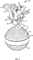
FIG. 1 illustrates a perspective view of an avian distractor device for preventing collision of birds and other wildlife with overhead structures (i.e. power lines), in accordance with an exemplary embodiment of the present invention; -
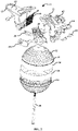
FIG. 2 illustrates an exploded view of the avian distractor device, in accordance with an exemplary embodiment of the present invention; -
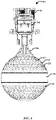
FIG. 3 illustrates a perspective view of a bottom hemisphere of the spherical diverter with a swivel molded structure, in accordance with an exemplary embodiment of the present invention; -
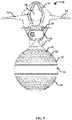
FIG. 4 illustrates a Side view of the avian distractor device, in accordance with an exemplary embodiment of the present invention; -
FIG. 5 illustrates a perspective view the avian distractor device that is attached a cylindrical substrate, (i.e could be a powerline, communications line or another similar structure not necessarily cylindrical in cross section). in accordance with an exemplary embodiment of the present invention; -
FIG. 6 illustrates a side view of the avian distractor device, in accordance with an exemplary embodiment of the present invention; and -
FIG. 7 illustrates a sectional view of the avian distractor device, in accordance with an exemplary embodiment of the present invention. - The particular values and configurations discussed in these non-limiting examples can be varied and are cited merely to illustrate at least one embodiment and are not intended to limit the scope thereof.
- In the following, numerous specific details are set forth to provide a thorough description of various embodiments. Certain embodiments may be practiced without these specific details or with some variations in detail. In some instances, certain features are described in less detail so as not to obscure other aspects. The level of detail associated with each of the elements or features should not be construed to qualify the novelty or importance of one feature over the others.
- The claimed subject matter has been provided here with reference to one or more features or embodiments. Those skilled in the art will recognize and appreciate that, despite of the detailed nature of the exemplary embodiments provided here; changes and modifications may be applied to said embodiments without limiting or departing from the generally intended scope. These and various other adaptations and combinations of the embodiments provided here are within the scope of the disclosed subject matter as defined by the claims and their full set of equivalents. Like numbers refer to like elements throughout.
- The present invention relates to an avian distractor device for preventing collision of birds and other wildlife with overhead structures, (i.e. power lines, communication lines and structures). The avian distractor device is relatively inexpensive, easy to assemble, sturdy, durable, modular and easy to install. The avian distractor device is capable of reducing wind loading on the overall component and on a connection zone between a clamp and an indicator in windy conditions. The avian distractor device is also capable of increasing low light dawn/dusk visibility to wildlife and is attached to a variety of structures.
- Referring to
FIG. 1 a perspective view of an avian distractor device (10) for preventing collision of birds and other wildlife with overhead power lines is illustrated, in accordance with an exemplary embodiment of the present invention. Note that inFIGS. 1-7 , identical or similar parts or components are generally indicated by identical reference numerals. The avian distractor device (10) includes a clamp (12) having a pair of jaws (13, 14) attached to a hinge (16) via a plurality of springs (18, 38). The clamp (12) is composed of a locking member (52) disposed in communication with the pair of jaws (13, 14) to rigidly hold a conductor (20) of different sizes using the spring force. The locking member (52) further includes threaded inserts and bolt to connect the spherical diverter (22), the hinge (16) and the clamp (12). The locking member (52) is composed of a locking cover (45, 46) for covering the locking member (52) of the clamp (12) via screws (44) to rigidly hold and lock the conductor (20). Note that the locking cover (45, 46) is made of plastic or other nonconductive, weather resistant material, based on design consideration. - In a preferred embodiment, the avian distractor device (10) is attached to the conductor (20) through the clamp (12). Note that as utilized herein, the term conductor (20) generally refers to an elongate object such as a solid or tubular rod, pipe, strut, radio masts or towers, or the like and specifically relate to a cable, wire, line, cord, conductor, or the like suspended above the ground, such as overhead power transmission lines, whether non-energized or low voltage, medium voltage, high voltage, extra high voltage, ultrahigh voltage, as aluminum conductors reinforced with steel, bundle conductors, ground conductors, aerial cables, antennas, electrical fence, overhead cable, or the like.
- Referring to
FIG. 2 an exploded view of the avian distractor device (10) is illustrated, in accordance with an exemplary embodiment of the present invention. The avian distractor device (10) is composed of a spherical diverter (22) having two interlocking hemispheres (23, 33). The interlocking hemispheres (23, 33) are mechanically interlocked via a male and female slot (24, 26) located at the ends of the interlocking hemispheres (23, 33). The spherical diverter (22) is reflective and rotates in response to the wind. A swivel molded structure (50) is located at an inner portion of the lower hemisphere (33), as shown inFIG. 3 . A fastener (36) is threaded via a center portion of the spherical diverter (22) via the swivel molded structure (50) to rotatably attach the spherical diverter (22) to the hinge (16) and the clamp (12), as shown inFIG. 3 . In general, a swivel is a cylindrical rod that can turn freely within a support structure. The rod is usually prevented from slipping out by a nut, washer or thickening of the rod. The lower hemisphere (33) is attached to the ends of the rod or the center. The swivel molded structure (50) located at the lower hemisphere (33) of the spherical diverter (22) allow the spherical diverter (22) to rotate as explained above. - A retro-reflective tape (28) is encircled on a central portion of the spherical diverter (22) to enhance visibility of the device (10). In general, the retro-reflective tape (28) works by reflecting light back to the light source only. In a preferred embodiment, the spherical diverter (22) is composed of a polymer material such as, for example, polycarbonate material or polyacetal material with a photo-phosphorence pigment to induce a night glow effect onto the spherical diverter (22), based on design consideration. In general, phosphorescence is a type of photoluminescence related to fluorescence. Unlike fluorescence, a phosphorescent material does not immediately re-emit the radiation it absorbs. The slower time scales of the re-emission are associated with "forbidden" energy state transitions in quantum mechanics. As these transitions occur very slowly in certain materials, absorbed radiation is re-emitted at a lower intensity for up to several hours after the original excitation. The retro-reflective tape (28) is adhesively attached to the central portion of the spherical diverter (22), as shown in
FIG. 4 . The retro-reflective tape (28) refracts and reflects ambient light to make the diverter (22) visible to the wildlife. Note that the retro-reflective tape (28) is composed of an orange color tape, a yellow color tape or a green color tape to enhance visibility of the device (10) to the wildlife, based on design consideration. - Referring to
FIG. 5 a side view of the avian distractor device (10) is illustrated, in accordance with an exemplary embodiment of the present invention. The jaws (13, 14) are composed of a plurality of rubber inserts (40) with serrations for better flexibility and cushioning effect to hold the conductor (20). The pair of jaws (13, 14) snaps the clamp (12) on and off around the conductor (20). The avian distractor device (10) is opened by hand and closed in a "snap fit" process around the conductor (20) which can be a live conductor or guy wire. In a preferred embodiment, the avian distractor device (10) is fitted to the conductor (10) by an insulated rod. The avian distractor device (10) is also drone installable and is held by a drone using an attachment hole (62, 63) in the extension of the clamp (12), based on design consideration. These attachment holes (62, 63) also serve to provide a holding point used to open the clamp (12). - The spherical diverter (22) is translucent so that light enters within the material and emerge out through the retro-reflective tape (28) to help brighten the phosphorescence colors. A plurality of dimples (32) is located on an external surface of the spherical diverter (22) and on a connection zone between the clamp (12) and the spherical diverter (22) to reduce a drag force on the device (10). In a preferred embodiment, the dimples (32) are spherical in shape to reduce a drag force on the device (10). The avian distractor device (10) uses light through reflectance and refraction, and motion through rotation, oscillation and vibration to divert birds and wildlife away from the power line and other structures on which birds typically perch or against which birds may collide.
- Referring to
FIG. 6 a front view the avian distractor device (10) that holds the conductor (20) is illustrated, in accordance with an exemplary embodiment of the present invention. Again as reminder, inFIGS. 1-7 , identical or similar parts or components are generally indicated by identical reference numerals. The spherical shape of the diverter (22) reflects any available light in all directions and is visible from all directions including above or below the diverter (22). The clamp (12) is made of polyamide structure with ultraviolet and thermal stability to increase visibility of the device (10) to the wildlife. The polyamide structure absorbs stray light in low light conditions and will not break down under natural sunlight exposure. This type of plastic advantageously magnifies and enhances the phosphorescence material that is applied to the surface of the substrate. - Referring to
FIG. 7 a sectional view of the avian distractor device (10) is illustrated, in accordance with an exemplary embodiment of the present invention. The diverter (22) is preferably substantially spherical. The spherical diverter (22) with photo-phosphorence pigments induces night glow effect on to the spherical diverter (22). The colors on the reflective tape (28) of the diverter (22) during rotation, oscillation, and/or vibrations is enhanced to approaching birds, animals and bats and thereby causing the wildlife to avoid collisions with wires. Note that the embodiments discussed herein should not be construed in any limited sense. It can be appreciated that such embodiments reveal details of the structure of a preferred form necessary for a better understanding of the invention and may be subject to change by skilled persons within the scope of the invention without departing from the concept thereof. - The avian distractor device (10) is lightweight, easily and quickly installed by hand. The positive grip on the conductor (20) ensures the avian diverter device (10) remains in the applied location. The avian distractor device (10) has a long service life without deterioration of material properties with minimal wind resistance. The clamp (12) snaps on and off quickly and easily. The clamp (12) is fitted by hand or by drone. The avian distractor device (10) can be any suitable size, shape, and configuration, and has a sufficiently large wind-catching surface, and is large enough to deter birds or other wildlife.
- It will be appreciated that variations of the above-disclosed and other features and functions, or alternatives thereof, may be desirably combined into many other different systems or applications. Also that various presently unforeseen or unanticipated alternatives, modifications, variations or improvements therein may be subsequently made by those skilled in the art which are also intended to be encompassed by the following claims.
Claims (9)
- An avian distractor device (10), comprising:a clamp (12) having a pair of jaws (13, 14) attached to a hinge (16) via a plurality of springs (18, 38) and a locking member (52) disposed in communication with the pair of jaws (13, 14) to rigidly hold a conductor (20) of different sizes using the spring force;a spherical diverter (22) having two interlocking hemispheres (23, 33) mechanically interlocked via a male and female slot (24, 26) located at its end and a fastener (36) threaded via a center portion of the spherical diverter (22) via a swivel molded structure (50) located at an inner side of the lower hemisphere (33) to rotatably attach the spherical diverter (22) to the hinge (16) and the clamp (12); anda retro-reflective tape (28) encircled on a central portion of the spherical diverter (22) to enhance visibility of the device (10) to the wildlife and a plurality of dimples (32) located on an external surface of the spherical diverter (22) and on a connection zone between the clamp (12) and the spherical diverter (22) to reduce a drag force on the device (10).
- The device (10) of claim 1, wherein the locking member (52) comprises a locking cover (45, 46) for covering the locking member (52) of the clamp (12) via screws (44) to rigidly hold and lock the conductor (20).
- The device (10) of claim 1, wherein the jaws (13, 14) comprises a plurality of rubber inserts (40) to flexibly hold the conductor (20).
- The device (10) of claim 1, wherein jaws (13, 14) snaps the clamp (12) on and off around the conductor (20) and is fitted by hand, an insulated rod or by a drone using an attachment hole (62, 63) located on the jaws (13, 14).
- The device (10) of claim 1, wherein the clamp (12) is composed of a polyamide structure with an ultraviolet and thermal stability to enhance visibility and ensure long durability.
- The device (10) of claim 1, wherein the spherical diverter (22) is reflective and rotate in response to the wind.
- The device (10) of claim 1, wherein the spherical diverter (22) is composed of a polymer material with a photo-phosphorence pigment to induce a night glow effect onto the spherical diverter (22).
- The device (10) of claims 1 and 7, wherein the polymer material comprises a polycarbonate material or a polyacetal material.
- The device (10) of claim 1, wherein the retro-reflective tape (28) is composed of an orange color tape, a yellow color tape or a green color tape.
Applications Claiming Priority (1)
| Application Number | Priority Date | Filing Date | Title |
|---|---|---|---|
| IN202041053180 | 2020-12-07 |
Publications (2)
| Publication Number | Publication Date |
|---|---|
| EP4008183A1 true EP4008183A1 (en) | 2022-06-08 |
| EP4008183B1 EP4008183B1 (en) | 2024-05-01 |
Family
ID=78822052
Family Applications (1)
| Application Number | Title | Priority Date | Filing Date |
|---|---|---|---|
| EP21212512.4A Active EP4008183B1 (en) | 2020-12-07 | 2021-12-06 | Avian distractor device |
Country Status (3)
| Country | Link |
|---|---|
| US (1) | US12507689B2 (en) |
| EP (1) | EP4008183B1 (en) |
| CN (1) | CN114586764B (en) |
Families Citing this family (2)
| Publication number | Priority date | Publication date | Assignee | Title |
|---|---|---|---|---|
| WO2020146923A1 (en) * | 2019-01-14 | 2020-07-23 | Balmoral Engineering Pty Ltd | Apparatus for securing device to transmission lines |
| EP4742469A1 (en) * | 2024-11-11 | 2026-05-13 | Hammar, Lars | Suspension device |
Citations (4)
| Publication number | Priority date | Publication date | Assignee | Title |
|---|---|---|---|---|
| JP2008271676A (en) * | 2007-04-18 | 2008-11-06 | Chugoku Electric Power Co Inc:The | Bird clash preventer |
| ES2333397A1 (en) * | 2009-11-12 | 2010-02-19 | Sociedad Anonima De Preformados Metalicos | Cable beacon (Machine-translation by Google Translate, not legally binding) |
| US8869732B1 (en) * | 2009-06-02 | 2014-10-28 | Ab Hammarprodukter | Bird diverter |
| US9331465B2 (en) * | 2013-03-14 | 2016-05-03 | San Diego Gas & Electric Company | Aerial marker assemblies, components and related methods |
Family Cites Families (11)
| Publication number | Priority date | Publication date | Assignee | Title |
|---|---|---|---|---|
| US5421266A (en) | 1993-06-04 | 1995-06-06 | Sociedad Anonima De Performados Metallicos | Device for the installation of beacons for power lines |
| UY29780A1 (en) * | 2005-09-05 | 2007-03-30 | Interconexion Electrica S A E | BIRD FLIGHT DEVICE DEVICE AND ITS CABLE OR AIR WIRE HOLDING SYSTEM |
| SE533763C2 (en) * | 2009-05-04 | 2010-12-28 | Lars Hammar | Suspension device |
| US9706767B2 (en) | 2011-04-08 | 2017-07-18 | Power Line Sentry, Llc | Collision aversion system |
| US8438998B2 (en) | 2011-04-08 | 2013-05-14 | Power Line Sentry, Llc | Avian flight diverter |
| CN203424209U (en) * | 2013-09-08 | 2014-02-12 | 国网山东齐河县供电公司 | Spheroidal bird scarer |
| CA2929124C (en) | 2013-11-22 | 2022-10-18 | Preformed Line Products | Power line protection device |
| CN105552782B (en) * | 2016-02-23 | 2017-05-31 | 河南安鑫电子有限公司 | The method for installing bird-scaring unit to power transmission tower using servicing unit and by unmanned plane |
| AU2016216676A1 (en) * | 2016-03-23 | 2017-10-12 | Balmoral Engineering Pty Ltd | Improved Marker Device |
| CN107464680A (en) * | 2017-10-11 | 2017-12-12 | 溧阳市农电电力有限公司 | A kind of transformer protective cover |
| CN111296405A (en) * | 2020-03-24 | 2020-06-19 | 江苏引拓电力科技有限公司 | Intelligent ultrasonic bird repelling method |
-
2021
- 2021-12-02 CN CN202111457427.0A patent/CN114586764B/en active Active
- 2021-12-06 EP EP21212512.4A patent/EP4008183B1/en active Active
- 2021-12-07 US US17/544,475 patent/US12507689B2/en active Active
Patent Citations (4)
| Publication number | Priority date | Publication date | Assignee | Title |
|---|---|---|---|---|
| JP2008271676A (en) * | 2007-04-18 | 2008-11-06 | Chugoku Electric Power Co Inc:The | Bird clash preventer |
| US8869732B1 (en) * | 2009-06-02 | 2014-10-28 | Ab Hammarprodukter | Bird diverter |
| ES2333397A1 (en) * | 2009-11-12 | 2010-02-19 | Sociedad Anonima De Preformados Metalicos | Cable beacon (Machine-translation by Google Translate, not legally binding) |
| US9331465B2 (en) * | 2013-03-14 | 2016-05-03 | San Diego Gas & Electric Company | Aerial marker assemblies, components and related methods |
Non-Patent Citations (1)
| Title |
|---|
| RICK HARNESS: "Using an Unmanned Aerial Vehicle to Install Wire Markers to Mitigate Bird Collisions ENV-VISION: Environmental Vision", 25 May 2016 (2016-05-25), XP055593823, Retrieved from the Internet <URL:https://epristorage.blob.core.windows.net/documents/Rick%20Harness_EDM%20International.pdf> [retrieved on 20190604] * |
Also Published As
| Publication number | Publication date |
|---|---|
| US20220174937A1 (en) | 2022-06-09 |
| EP4008183B1 (en) | 2024-05-01 |
| US12507689B2 (en) | 2025-12-30 |
| CN114586764B (en) | 2025-11-21 |
| CN114586764A (en) | 2022-06-07 |
Similar Documents
| Publication | Publication Date | Title |
|---|---|---|
| EP4008183B1 (en) | Avian distractor device | |
| US20120255503A1 (en) | Avian flight diverter | |
| US8869732B1 (en) | Bird diverter | |
| US20130298845A1 (en) | Apparatuses, systems and methods for warning flying birds of hazards | |
| US9559510B2 (en) | Signalling device for a transmission line | |
| ES2409718T3 (en) | Bird flight diverter device and its fastening system to aerial cables or wires. | |
| US20180368389A1 (en) | Bird deterring structure and method | |
| US8627613B2 (en) | Avian nesting diverters and methods for using the same | |
| US6526905B2 (en) | Self-contained obstruction marker | |
| KR102284562B1 (en) | Device to expel bird for electric pole | |
| US20200275646A1 (en) | Device for powerline preservation | |
| CA2359217A1 (en) | Light-emitting device and support pillar assembly | |
| US10107465B2 (en) | Flagpole finial assembly | |
| CA2929124C (en) | Power line protection device | |
| JP5660384B2 (en) | Bird protection against polymer insulators | |
| KR101322305B1 (en) | Aid to navigation facilities with birds exterminator and solar power clamp | |
| US20150059228A1 (en) | Decoy device | |
| JP2602143B2 (en) | Electricity type wire tension detection type alarm sensor | |
| US20060186393A1 (en) | Modular fencing system | |
| CA2799919C (en) | Driveway marking device | |
| KR100590408B1 (en) | Underground Power Cable Support | |
| AU2005267520A1 (en) | Firefly bird flapper unit | |
| CN211183314U (en) | Ball head hanging ring | |
| JP2007014103A (en) | Luminous ring for electric line | |
| KR102030269B1 (en) | Apparatus for controlling Birds |
Legal Events
| Date | Code | Title | Description |
|---|---|---|---|
| PUAI | Public reference made under article 153(3) epc to a published international application that has entered the european phase |
Free format text: ORIGINAL CODE: 0009012 |
|
| STAA | Information on the status of an ep patent application or granted ep patent |
Free format text: STATUS: THE APPLICATION HAS BEEN PUBLISHED |
|
| AK | Designated contracting states |
Kind code of ref document: A1 Designated state(s): AL AT BE BG CH CY CZ DE DK EE ES FI FR GB GR HR HU IE IS IT LI LT LU LV MC MK MT NL NO PL PT RO RS SE SI SK SM TR |
|
| STAA | Information on the status of an ep patent application or granted ep patent |
Free format text: STATUS: REQUEST FOR EXAMINATION WAS MADE |
|
| 17P | Request for examination filed |
Effective date: 20221201 |
|
| RBV | Designated contracting states (corrected) |
Designated state(s): AL AT BE BG CH CY CZ DE DK EE ES FI FR GB GR HR HU IE IS IT LI LT LU LV MC MK MT NL NO PL PT RO RS SE SI SK SM TR |
|
| RIC1 | Information provided on ipc code assigned before grant |
Ipc: A01M 29/08 20110101ALI20231122BHEP Ipc: A01M 29/00 20110101AFI20231122BHEP |
|
| GRAP | Despatch of communication of intention to grant a patent |
Free format text: ORIGINAL CODE: EPIDOSNIGR1 |
|
| STAA | Information on the status of an ep patent application or granted ep patent |
Free format text: STATUS: GRANT OF PATENT IS INTENDED |
|
| INTG | Intention to grant announced |
Effective date: 20240123 |
|
| GRAS | Grant fee paid |
Free format text: ORIGINAL CODE: EPIDOSNIGR3 |
|
| GRAA | (expected) grant |
Free format text: ORIGINAL CODE: 0009210 |
|
| STAA | Information on the status of an ep patent application or granted ep patent |
Free format text: STATUS: THE PATENT HAS BEEN GRANTED |
|
| AK | Designated contracting states |
Kind code of ref document: B1 Designated state(s): AL AT BE BG CH CY CZ DE DK EE ES FI FR GB GR HR HU IE IS IT LI LT LU LV MC MK MT NL NO PL PT RO RS SE SI SK SM TR |
|
| REG | Reference to a national code |
Ref country code: GB Ref legal event code: FG4D |
|
| REG | Reference to a national code |
Ref country code: CH Ref legal event code: EP |
|
| REG | Reference to a national code |
Ref country code: IE Ref legal event code: FG4D |
|
| REG | Reference to a national code |
Ref country code: DE Ref legal event code: R096 Ref document number: 602021012620 Country of ref document: DE |
|
| RAP2 | Party data changed (patent owner data changed or rights of a patent transferred) |
Owner name: TE CONNECTIVITY IRELAND LIMITED Owner name: TE CONNECTIVITY SOLUTIONS GMBH |
|
| REG | Reference to a national code |
Ref country code: LT Ref legal event code: MG9D |
|
| REG | Reference to a national code |
Ref country code: NL Ref legal event code: MP Effective date: 20240501 |
|
| PG25 | Lapsed in a contracting state [announced via postgrant information from national office to epo] |
Ref country code: IS Free format text: LAPSE BECAUSE OF FAILURE TO SUBMIT A TRANSLATION OF THE DESCRIPTION OR TO PAY THE FEE WITHIN THE PRESCRIBED TIME-LIMIT Effective date: 20240901 |
|
| PG25 | Lapsed in a contracting state [announced via postgrant information from national office to epo] |
Ref country code: BG Free format text: LAPSE BECAUSE OF FAILURE TO SUBMIT A TRANSLATION OF THE DESCRIPTION OR TO PAY THE FEE WITHIN THE PRESCRIBED TIME-LIMIT Effective date: 20240501 |
|
| PG25 | Lapsed in a contracting state [announced via postgrant information from national office to epo] |
Ref country code: FI Free format text: LAPSE BECAUSE OF FAILURE TO SUBMIT A TRANSLATION OF THE DESCRIPTION OR TO PAY THE FEE WITHIN THE PRESCRIBED TIME-LIMIT Effective date: 20240501 Ref country code: HR Free format text: LAPSE BECAUSE OF FAILURE TO SUBMIT A TRANSLATION OF THE DESCRIPTION OR TO PAY THE FEE WITHIN THE PRESCRIBED TIME-LIMIT Effective date: 20240501 |
|
| PG25 | Lapsed in a contracting state [announced via postgrant information from national office to epo] |
Ref country code: GR Free format text: LAPSE BECAUSE OF FAILURE TO SUBMIT A TRANSLATION OF THE DESCRIPTION OR TO PAY THE FEE WITHIN THE PRESCRIBED TIME-LIMIT Effective date: 20240802 |
|
| PG25 | Lapsed in a contracting state [announced via postgrant information from national office to epo] |
Ref country code: PT Free format text: LAPSE BECAUSE OF FAILURE TO SUBMIT A TRANSLATION OF THE DESCRIPTION OR TO PAY THE FEE WITHIN THE PRESCRIBED TIME-LIMIT Effective date: 20240902 |
|
| REG | Reference to a national code |
Ref country code: AT Ref legal event code: MK05 Ref document number: 1681059 Country of ref document: AT Kind code of ref document: T Effective date: 20240501 |
|
| PG25 | Lapsed in a contracting state [announced via postgrant information from national office to epo] |
Ref country code: NL Free format text: LAPSE BECAUSE OF FAILURE TO SUBMIT A TRANSLATION OF THE DESCRIPTION OR TO PAY THE FEE WITHIN THE PRESCRIBED TIME-LIMIT Effective date: 20240501 |
|
| PG25 | Lapsed in a contracting state [announced via postgrant information from national office to epo] |
Ref country code: ES Free format text: LAPSE BECAUSE OF FAILURE TO SUBMIT A TRANSLATION OF THE DESCRIPTION OR TO PAY THE FEE WITHIN THE PRESCRIBED TIME-LIMIT Effective date: 20240501 |
|
| PG25 | Lapsed in a contracting state [announced via postgrant information from national office to epo] |
Ref country code: AT Free format text: LAPSE BECAUSE OF FAILURE TO SUBMIT A TRANSLATION OF THE DESCRIPTION OR TO PAY THE FEE WITHIN THE PRESCRIBED TIME-LIMIT Effective date: 20240501 |
|
| PG25 | Lapsed in a contracting state [announced via postgrant information from national office to epo] |
Ref country code: PL Free format text: LAPSE BECAUSE OF FAILURE TO SUBMIT A TRANSLATION OF THE DESCRIPTION OR TO PAY THE FEE WITHIN THE PRESCRIBED TIME-LIMIT Effective date: 20240501 |
|
| PG25 | Lapsed in a contracting state [announced via postgrant information from national office to epo] |
Ref country code: LV Free format text: LAPSE BECAUSE OF FAILURE TO SUBMIT A TRANSLATION OF THE DESCRIPTION OR TO PAY THE FEE WITHIN THE PRESCRIBED TIME-LIMIT Effective date: 20240501 |
|
| PG25 | Lapsed in a contracting state [announced via postgrant information from national office to epo] |
Ref country code: PT Free format text: LAPSE BECAUSE OF FAILURE TO SUBMIT A TRANSLATION OF THE DESCRIPTION OR TO PAY THE FEE WITHIN THE PRESCRIBED TIME-LIMIT Effective date: 20240902 Ref country code: PL Free format text: LAPSE BECAUSE OF FAILURE TO SUBMIT A TRANSLATION OF THE DESCRIPTION OR TO PAY THE FEE WITHIN THE PRESCRIBED TIME-LIMIT Effective date: 20240501 Ref country code: NO Free format text: LAPSE BECAUSE OF FAILURE TO SUBMIT A TRANSLATION OF THE DESCRIPTION OR TO PAY THE FEE WITHIN THE PRESCRIBED TIME-LIMIT Effective date: 20240801 Ref country code: NL Free format text: LAPSE BECAUSE OF FAILURE TO SUBMIT A TRANSLATION OF THE DESCRIPTION OR TO PAY THE FEE WITHIN THE PRESCRIBED TIME-LIMIT Effective date: 20240501 Ref country code: LV Free format text: LAPSE BECAUSE OF FAILURE TO SUBMIT A TRANSLATION OF THE DESCRIPTION OR TO PAY THE FEE WITHIN THE PRESCRIBED TIME-LIMIT Effective date: 20240501 Ref country code: IS Free format text: LAPSE BECAUSE OF FAILURE TO SUBMIT A TRANSLATION OF THE DESCRIPTION OR TO PAY THE FEE WITHIN THE PRESCRIBED TIME-LIMIT Effective date: 20240901 Ref country code: HR Free format text: LAPSE BECAUSE OF FAILURE TO SUBMIT A TRANSLATION OF THE DESCRIPTION OR TO PAY THE FEE WITHIN THE PRESCRIBED TIME-LIMIT Effective date: 20240501 Ref country code: GR Free format text: LAPSE BECAUSE OF FAILURE TO SUBMIT A TRANSLATION OF THE DESCRIPTION OR TO PAY THE FEE WITHIN THE PRESCRIBED TIME-LIMIT Effective date: 20240802 Ref country code: FI Free format text: LAPSE BECAUSE OF FAILURE TO SUBMIT A TRANSLATION OF THE DESCRIPTION OR TO PAY THE FEE WITHIN THE PRESCRIBED TIME-LIMIT Effective date: 20240501 Ref country code: ES Free format text: LAPSE BECAUSE OF FAILURE TO SUBMIT A TRANSLATION OF THE DESCRIPTION OR TO PAY THE FEE WITHIN THE PRESCRIBED TIME-LIMIT Effective date: 20240501 Ref country code: BG Free format text: LAPSE BECAUSE OF FAILURE TO SUBMIT A TRANSLATION OF THE DESCRIPTION OR TO PAY THE FEE WITHIN THE PRESCRIBED TIME-LIMIT Effective date: 20240501 Ref country code: AT Free format text: LAPSE BECAUSE OF FAILURE TO SUBMIT A TRANSLATION OF THE DESCRIPTION OR TO PAY THE FEE WITHIN THE PRESCRIBED TIME-LIMIT Effective date: 20240501 Ref country code: RS Free format text: LAPSE BECAUSE OF FAILURE TO SUBMIT A TRANSLATION OF THE DESCRIPTION OR TO PAY THE FEE WITHIN THE PRESCRIBED TIME-LIMIT Effective date: 20240801 |
|
| PG25 | Lapsed in a contracting state [announced via postgrant information from national office to epo] |
Ref country code: DK Free format text: LAPSE BECAUSE OF FAILURE TO SUBMIT A TRANSLATION OF THE DESCRIPTION OR TO PAY THE FEE WITHIN THE PRESCRIBED TIME-LIMIT Effective date: 20240501 |
|
| PG25 | Lapsed in a contracting state [announced via postgrant information from national office to epo] |
Ref country code: EE Free format text: LAPSE BECAUSE OF FAILURE TO SUBMIT A TRANSLATION OF THE DESCRIPTION OR TO PAY THE FEE WITHIN THE PRESCRIBED TIME-LIMIT Effective date: 20240501 |
|
| PG25 | Lapsed in a contracting state [announced via postgrant information from national office to epo] |
Ref country code: CZ Free format text: LAPSE BECAUSE OF FAILURE TO SUBMIT A TRANSLATION OF THE DESCRIPTION OR TO PAY THE FEE WITHIN THE PRESCRIBED TIME-LIMIT Effective date: 20240501 |
|
| PG25 | Lapsed in a contracting state [announced via postgrant information from national office to epo] |
Ref country code: RO Free format text: LAPSE BECAUSE OF FAILURE TO SUBMIT A TRANSLATION OF THE DESCRIPTION OR TO PAY THE FEE WITHIN THE PRESCRIBED TIME-LIMIT Effective date: 20240501 Ref country code: SK Free format text: LAPSE BECAUSE OF FAILURE TO SUBMIT A TRANSLATION OF THE DESCRIPTION OR TO PAY THE FEE WITHIN THE PRESCRIBED TIME-LIMIT Effective date: 20240501 |
|
| PG25 | Lapsed in a contracting state [announced via postgrant information from national office to epo] |
Ref country code: SM Free format text: LAPSE BECAUSE OF FAILURE TO SUBMIT A TRANSLATION OF THE DESCRIPTION OR TO PAY THE FEE WITHIN THE PRESCRIBED TIME-LIMIT Effective date: 20240501 |
|
| PG25 | Lapsed in a contracting state [announced via postgrant information from national office to epo] |
Ref country code: SM Free format text: LAPSE BECAUSE OF FAILURE TO SUBMIT A TRANSLATION OF THE DESCRIPTION OR TO PAY THE FEE WITHIN THE PRESCRIBED TIME-LIMIT Effective date: 20240501 Ref country code: SK Free format text: LAPSE BECAUSE OF FAILURE TO SUBMIT A TRANSLATION OF THE DESCRIPTION OR TO PAY THE FEE WITHIN THE PRESCRIBED TIME-LIMIT Effective date: 20240501 Ref country code: RO Free format text: LAPSE BECAUSE OF FAILURE TO SUBMIT A TRANSLATION OF THE DESCRIPTION OR TO PAY THE FEE WITHIN THE PRESCRIBED TIME-LIMIT Effective date: 20240501 Ref country code: EE Free format text: LAPSE BECAUSE OF FAILURE TO SUBMIT A TRANSLATION OF THE DESCRIPTION OR TO PAY THE FEE WITHIN THE PRESCRIBED TIME-LIMIT Effective date: 20240501 Ref country code: DK Free format text: LAPSE BECAUSE OF FAILURE TO SUBMIT A TRANSLATION OF THE DESCRIPTION OR TO PAY THE FEE WITHIN THE PRESCRIBED TIME-LIMIT Effective date: 20240501 Ref country code: CZ Free format text: LAPSE BECAUSE OF FAILURE TO SUBMIT A TRANSLATION OF THE DESCRIPTION OR TO PAY THE FEE WITHIN THE PRESCRIBED TIME-LIMIT Effective date: 20240501 |
|
| REG | Reference to a national code |
Ref country code: DE Ref legal event code: R097 Ref document number: 602021012620 Country of ref document: DE |
|
| PLBE | No opposition filed within time limit |
Free format text: ORIGINAL CODE: 0009261 |
|
| STAA | Information on the status of an ep patent application or granted ep patent |
Free format text: STATUS: NO OPPOSITION FILED WITHIN TIME LIMIT |
|
| 26N | No opposition filed |
Effective date: 20250204 |
|
| PG25 | Lapsed in a contracting state [announced via postgrant information from national office to epo] |
Ref country code: SI Free format text: LAPSE BECAUSE OF FAILURE TO SUBMIT A TRANSLATION OF THE DESCRIPTION OR TO PAY THE FEE WITHIN THE PRESCRIBED TIME-LIMIT Effective date: 20240501 |
|
| REG | Reference to a national code |
Ref country code: DE Ref legal event code: R119 Ref document number: 602021012620 Country of ref document: DE |
|
| PG25 | Lapsed in a contracting state [announced via postgrant information from national office to epo] |
Ref country code: MC Free format text: LAPSE BECAUSE OF FAILURE TO SUBMIT A TRANSLATION OF THE DESCRIPTION OR TO PAY THE FEE WITHIN THE PRESCRIBED TIME-LIMIT Effective date: 20240501 |
|
| REG | Reference to a national code |
Ref country code: CH Ref legal event code: PL |
|
| PG25 | Lapsed in a contracting state [announced via postgrant information from national office to epo] |
Ref country code: LU Free format text: LAPSE BECAUSE OF NON-PAYMENT OF DUE FEES Effective date: 20241206 |
|
| PG25 | Lapsed in a contracting state [announced via postgrant information from national office to epo] |
Ref country code: SE Free format text: LAPSE BECAUSE OF FAILURE TO SUBMIT A TRANSLATION OF THE DESCRIPTION OR TO PAY THE FEE WITHIN THE PRESCRIBED TIME-LIMIT Effective date: 20240501 |
|
| REG | Reference to a national code |
Ref country code: BE Ref legal event code: MM Effective date: 20241231 |
|
| PG25 | Lapsed in a contracting state [announced via postgrant information from national office to epo] |
Ref country code: DE Free format text: LAPSE BECAUSE OF NON-PAYMENT OF DUE FEES Effective date: 20250701 |
|
| PG25 | Lapsed in a contracting state [announced via postgrant information from national office to epo] |
Ref country code: BE Free format text: LAPSE BECAUSE OF NON-PAYMENT OF DUE FEES Effective date: 20241231 |
|
| PGFP | Annual fee paid to national office [announced via postgrant information from national office to epo] |
Ref country code: FR Payment date: 20250930 Year of fee payment: 5 |
|
| PG25 | Lapsed in a contracting state [announced via postgrant information from national office to epo] |
Ref country code: CH Free format text: LAPSE BECAUSE OF NON-PAYMENT OF DUE FEES Effective date: 20241231 |
|
| PG25 | Lapsed in a contracting state [announced via postgrant information from national office to epo] |
Ref country code: IE Free format text: LAPSE BECAUSE OF NON-PAYMENT OF DUE FEES Effective date: 20241206 |
|
| PGFP | Annual fee paid to national office [announced via postgrant information from national office to epo] |
Ref country code: GB Payment date: 20251001 Year of fee payment: 5 |
|
| PGFP | Annual fee paid to national office [announced via postgrant information from national office to epo] |
Ref country code: IT Payment date: 20251121 Year of fee payment: 5 |
|
| PG25 | Lapsed in a contracting state [announced via postgrant information from national office to epo] |
Ref country code: CY Free format text: LAPSE BECAUSE OF FAILURE TO SUBMIT A TRANSLATION OF THE DESCRIPTION OR TO PAY THE FEE WITHIN THE PRESCRIBED TIME-LIMIT; INVALID AB INITIO Effective date: 20211206 |
|
| PG25 | Lapsed in a contracting state [announced via postgrant information from national office to epo] |
Ref country code: TR Free format text: LAPSE BECAUSE OF FAILURE TO SUBMIT A TRANSLATION OF THE DESCRIPTION OR TO PAY THE FEE WITHIN THE PRESCRIBED TIME-LIMIT Effective date: 20240501 |
|
| PG25 | Lapsed in a contracting state [announced via postgrant information from national office to epo] |
Ref country code: HU Free format text: LAPSE BECAUSE OF FAILURE TO SUBMIT A TRANSLATION OF THE DESCRIPTION OR TO PAY THE FEE WITHIN THE PRESCRIBED TIME-LIMIT; INVALID AB INITIO Effective date: 20211206 |
|
| PG25 | Lapsed in a contracting state [announced via postgrant information from national office to epo] |
Ref country code: LT Free format text: LAPSE BECAUSE OF FAILURE TO SUBMIT A TRANSLATION OF THE DESCRIPTION OR TO PAY THE FEE WITHIN THE PRESCRIBED TIME-LIMIT Effective date: 20240501 |