EP4007871B1 - Power electronics cooling arrangement - Google Patents
Power electronics cooling arrangement Download PDFInfo
- Publication number
- EP4007871B1 EP4007871B1 EP20847063.3A EP20847063A EP4007871B1 EP 4007871 B1 EP4007871 B1 EP 4007871B1 EP 20847063 A EP20847063 A EP 20847063A EP 4007871 B1 EP4007871 B1 EP 4007871B1
- Authority
- EP
- European Patent Office
- Prior art keywords
- refrigerant
- compressor
- mode
- cooling
- controller
- Prior art date
- Legal status (The legal status is an assumption and is not a legal conclusion. Google has not performed a legal analysis and makes no representation as to the accuracy of the status listed.)
- Active
Links
Images


Classifications
-
- H—ELECTRICITY
- H02—GENERATION; CONVERSION OR DISTRIBUTION OF ELECTRIC POWER
- H02K—DYNAMO-ELECTRIC MACHINES
- H02K9/00—Arrangements for cooling or ventilating
- H02K9/10—Arrangements for cooling or ventilating by gaseous cooling medium flowing in closed circuit, a part of which is external to the machine casing
-
- F—MECHANICAL ENGINEERING; LIGHTING; HEATING; WEAPONS; BLASTING
- F04—POSITIVE - DISPLACEMENT MACHINES FOR LIQUIDS; PUMPS FOR LIQUIDS OR ELASTIC FLUIDS
- F04D—NON-POSITIVE-DISPLACEMENT PUMPS
- F04D17/00—Radial-flow pumps, e.g. centrifugal pumps; Helico-centrifugal pumps
- F04D17/08—Centrifugal pumps
- F04D17/10—Centrifugal pumps for compressing or evacuating
- F04D17/12—Multi-stage pumps
- F04D17/122—Multi-stage pumps the individual rotor discs being, one for each stage, on a common shaft and axially spaced, e.g. conventional centrifugal multi- stage compressors
-
- F—MECHANICAL ENGINEERING; LIGHTING; HEATING; WEAPONS; BLASTING
- F04—POSITIVE - DISPLACEMENT MACHINES FOR LIQUIDS; PUMPS FOR LIQUIDS OR ELASTIC FLUIDS
- F04D—NON-POSITIVE-DISPLACEMENT PUMPS
- F04D25/00—Pumping installations or systems
- F04D25/02—Units comprising pumps and their driving means
- F04D25/06—Units comprising pumps and their driving means the pump being electrically driven
-
- F—MECHANICAL ENGINEERING; LIGHTING; HEATING; WEAPONS; BLASTING
- F04—POSITIVE - DISPLACEMENT MACHINES FOR LIQUIDS; PUMPS FOR LIQUIDS OR ELASTIC FLUIDS
- F04D—NON-POSITIVE-DISPLACEMENT PUMPS
- F04D27/00—Control, e.g. regulation, of pumps, pumping installations or pumping systems specially adapted for elastic fluids
- F04D27/007—Conjoint control of two or more different functions
-
- F—MECHANICAL ENGINEERING; LIGHTING; HEATING; WEAPONS; BLASTING
- F04—POSITIVE - DISPLACEMENT MACHINES FOR LIQUIDS; PUMPS FOR LIQUIDS OR ELASTIC FLUIDS
- F04D—NON-POSITIVE-DISPLACEMENT PUMPS
- F04D27/00—Control, e.g. regulation, of pumps, pumping installations or pumping systems specially adapted for elastic fluids
- F04D27/02—Surge control
-
- F—MECHANICAL ENGINEERING; LIGHTING; HEATING; WEAPONS; BLASTING
- F04—POSITIVE - DISPLACEMENT MACHINES FOR LIQUIDS; PUMPS FOR LIQUIDS OR ELASTIC FLUIDS
- F04D—NON-POSITIVE-DISPLACEMENT PUMPS
- F04D29/00—Details, component parts, or accessories
- F04D29/58—Cooling; Heating; Diminishing heat transfer
- F04D29/5813—Cooling the control unit
-
- F—MECHANICAL ENGINEERING; LIGHTING; HEATING; WEAPONS; BLASTING
- F24—HEATING; RANGES; VENTILATING
- F24F—AIR-CONDITIONING; AIR-HUMIDIFICATION; VENTILATION; USE OF AIR CURRENTS FOR SCREENING
- F24F1/00—Room units for air-conditioning, e.g. separate or self-contained units or units receiving primary air from a central station
- F24F1/06—Separate outdoor units, e.g. outdoor unit to be linked to a separate room comprising a compressor and a heat exchanger
- F24F1/20—Electric components for separate outdoor units
- F24F1/24—Cooling of electric components
-
- F—MECHANICAL ENGINEERING; LIGHTING; HEATING; WEAPONS; BLASTING
- F25—REFRIGERATION OR COOLING; COMBINED HEATING AND REFRIGERATION SYSTEMS; HEAT PUMP SYSTEMS; MANUFACTURE OR STORAGE OF ICE; LIQUEFACTION SOLIDIFICATION OF GASES
- F25B—REFRIGERATION MACHINES, PLANTS OR SYSTEMS; COMBINED HEATING AND REFRIGERATION SYSTEMS; HEAT PUMP SYSTEMS
- F25B31/00—Compressor arrangements
- F25B31/006—Cooling of compressor or motor
-
- F—MECHANICAL ENGINEERING; LIGHTING; HEATING; WEAPONS; BLASTING
- F25—REFRIGERATION OR COOLING; COMBINED HEATING AND REFRIGERATION SYSTEMS; HEAT PUMP SYSTEMS; MANUFACTURE OR STORAGE OF ICE; LIQUEFACTION SOLIDIFICATION OF GASES
- F25B—REFRIGERATION MACHINES, PLANTS OR SYSTEMS; COMBINED HEATING AND REFRIGERATION SYSTEMS; HEAT PUMP SYSTEMS
- F25B31/00—Compressor arrangements
- F25B31/006—Cooling of compressor or motor
- F25B31/008—Cooling of compressor or motor by injecting a liquid
-
- F—MECHANICAL ENGINEERING; LIGHTING; HEATING; WEAPONS; BLASTING
- F25—REFRIGERATION OR COOLING; COMBINED HEATING AND REFRIGERATION SYSTEMS; HEAT PUMP SYSTEMS; MANUFACTURE OR STORAGE OF ICE; LIQUEFACTION SOLIDIFICATION OF GASES
- F25B—REFRIGERATION MACHINES, PLANTS OR SYSTEMS; COMBINED HEATING AND REFRIGERATION SYSTEMS; HEAT PUMP SYSTEMS
- F25B49/00—Arrangement or mounting of control or safety devices
- F25B49/02—Arrangement or mounting of control or safety devices for compression type machines, plants or systems
- F25B49/025—Motor control arrangements
-
- H—ELECTRICITY
- H02—GENERATION; CONVERSION OR DISTRIBUTION OF ELECTRIC POWER
- H02K—DYNAMO-ELECTRIC MACHINES
- H02K11/00—Structural association of dynamo-electric machines with electric components or with devices for shielding, monitoring or protection
- H02K11/20—Structural association of dynamo-electric machines with electric components or with devices for shielding, monitoring or protection for measuring, monitoring, testing, protecting or switching
- H02K11/25—Devices for sensing temperature, or actuated thereby
-
- F—MECHANICAL ENGINEERING; LIGHTING; HEATING; WEAPONS; BLASTING
- F05—INDEXING SCHEMES RELATING TO ENGINES OR PUMPS IN VARIOUS SUBCLASSES OF CLASSES F01-F04
- F05D—INDEXING SCHEME FOR ASPECTS RELATING TO NON-POSITIVE-DISPLACEMENT MACHINES OR ENGINES, GAS-TURBINES OR JET-PROPULSION PLANTS
- F05D2270/00—Control
- F05D2270/30—Control parameters, e.g. input parameters
- F05D2270/301—Pressure
- F05D2270/3011—Inlet pressure
-
- F—MECHANICAL ENGINEERING; LIGHTING; HEATING; WEAPONS; BLASTING
- F25—REFRIGERATION OR COOLING; COMBINED HEATING AND REFRIGERATION SYSTEMS; HEAT PUMP SYSTEMS; MANUFACTURE OR STORAGE OF ICE; LIQUEFACTION SOLIDIFICATION OF GASES
- F25B—REFRIGERATION MACHINES, PLANTS OR SYSTEMS; COMBINED HEATING AND REFRIGERATION SYSTEMS; HEAT PUMP SYSTEMS
- F25B2600/00—Control issues
- F25B2600/25—Control of valves
- F25B2600/2507—Flow-diverting valves
-
- F—MECHANICAL ENGINEERING; LIGHTING; HEATING; WEAPONS; BLASTING
- F25—REFRIGERATION OR COOLING; COMBINED HEATING AND REFRIGERATION SYSTEMS; HEAT PUMP SYSTEMS; MANUFACTURE OR STORAGE OF ICE; LIQUEFACTION SOLIDIFICATION OF GASES
- F25B—REFRIGERATION MACHINES, PLANTS OR SYSTEMS; COMBINED HEATING AND REFRIGERATION SYSTEMS; HEAT PUMP SYSTEMS
- F25B2700/00—Sensing or detecting of parameters; Sensors therefor
- F25B2700/19—Pressures
- F25B2700/193—Pressures of the compressor
- F25B2700/1933—Suction pressures
-
- F—MECHANICAL ENGINEERING; LIGHTING; HEATING; WEAPONS; BLASTING
- F25—REFRIGERATION OR COOLING; COMBINED HEATING AND REFRIGERATION SYSTEMS; HEAT PUMP SYSTEMS; MANUFACTURE OR STORAGE OF ICE; LIQUEFACTION SOLIDIFICATION OF GASES
- F25B—REFRIGERATION MACHINES, PLANTS OR SYSTEMS; COMBINED HEATING AND REFRIGERATION SYSTEMS; HEAT PUMP SYSTEMS
- F25B2700/00—Sensing or detecting of parameters; Sensors therefor
- F25B2700/21—Temperatures
- F25B2700/2115—Temperatures of a compressor or the drive means therefor
- F25B2700/21156—Temperatures of a compressor or the drive means therefor of the motor
-
- F—MECHANICAL ENGINEERING; LIGHTING; HEATING; WEAPONS; BLASTING
- F25—REFRIGERATION OR COOLING; COMBINED HEATING AND REFRIGERATION SYSTEMS; HEAT PUMP SYSTEMS; MANUFACTURE OR STORAGE OF ICE; LIQUEFACTION SOLIDIFICATION OF GASES
- F25B—REFRIGERATION MACHINES, PLANTS OR SYSTEMS; COMBINED HEATING AND REFRIGERATION SYSTEMS; HEAT PUMP SYSTEMS
- F25B2700/00—Sensing or detecting of parameters; Sensors therefor
- F25B2700/21—Temperatures
- F25B2700/2115—Temperatures of a compressor or the drive means therefor
- F25B2700/21156—Temperatures of a compressor or the drive means therefor of the motor
- F25B2700/21157—Temperatures of a compressor or the drive means therefor of the motor at the coil or rotor
-
- H—ELECTRICITY
- H02—GENERATION; CONVERSION OR DISTRIBUTION OF ELECTRIC POWER
- H02K—DYNAMO-ELECTRIC MACHINES
- H02K2213/00—Specific aspects, not otherwise provided for and not covered by codes H02K2201/00 - H02K2211/00
- H02K2213/09—Machines characterised by the presence of elements which are subject to variation, e.g. adjustable bearings, reconfigurable windings, variable pitch ventilators
Definitions
- Refrigerant compressors are used to circulate refrigerant in a chiller or heat pump via a refrigerant loop.
- Refrigerant loops are known to include a condenser, an expansion device, and an evaporator.
- Some compressors provide cooling to the motor and/or associated power electronics by conveying refrigerant from the main loop to the motor or other power electronics.
- US-B-6189335 teaches a multi-stage compressing refrigeration device for multi-stage compression of a refrigerant using a plurality of compressing means.
- low-stage compressing means and high-stage compressing means a condenser, first expanding means, an intermediate evaporator, second expanding means and a main evaporator constitute the refrigeration cycle.
- the refrigerant flowing out of the condenser is branched into the intermediate evaporator via the first expanding means and the main evaporator via the second expanding means. Heat exchange is performed between the refrigerant flowing into the second expanding means and the intermediate evaporator.
- the refrigerant flowing out of the main evaporator is sucked by the low-stage compressing means, and the refrigerant flowing out of the intermediate evaporator is sucked by the high-stage compressing means together with the refrigerant discharged from the low-stage compressing means.
- a refrigerant compressor comprises a first stage and a second stage downstream of the first stage, and a cooling line configured to cool power electronics.
- the cooling line is configured to be switched between a first mode and a second mode.
- the first mode is configured to dump refrigerant between the first stage and the second stage, and the second mode is configured to dump refrigerant upstream of the first stage.
- the cooling line is configured to draw refrigerant from a main refrigerant loop.
- the compressor is a centrifugal compressor and the first stage comprises a first impeller and the second stage comprises a second impeller.
- a controller is configured to switch between the first and second modes automatically in response to an input from a sensor.
- the controller is configured to monitor a suction pressure of the compressor, and the controller is configured to automatically switch to the second mode when the suction pressure is above a predetermined threshold.
- the controller is configured to automatically direct the return of the cooling flow in a real time manner based on operating conditions.
- the cooling line is configured to be switched between the first mode and the second mode by inserting a plug along the cooling line.
- the compressor comprises a housing, and the plug is accessible external to the housing.
- the plug is a threaded plug.
- a directional flow control valve is configured to switch between the first mode and the second mode.
- the second mode is used for high saturated suction temperature (SST), or low pressure difference cooling applications.
- a refrigerant system comprises a main refrigerant loop in communication with a condenser, an evaporator, and a compressor according to the exemplary aspect of the present disclosure.
- the power electronics comprises a silicon controlled rectifier
- the cooling line comprises a heat exchanger arranged to cool the silicon controlled rectifier
- a first plug is arranged in the heat exchanger.
- the cooling line is configured to be switched between the first mode and the second mode by inserting a plug along the cooling line.
- the compressor is arranged in a housing, and the plug is accessible external to the housing.
- a controller is configured to switch between the first and second modes automatically in response to an input from a sensor.
- the controller is set to direct the return of the cooling flow based on applications of normal comfort cooling or high SST cooling.
- the controller is configured to direct the return of the cooling flow in a real time manner based on operating conditions.
- the controller is configured to monitor a suction pressure of the compressor, and the controller is configured to automatically switch to the second mode when the suction pressure is above a predetermined threshold.
- FIG. 1 schematically illustrates a refrigerant cooling system 10.
- the refrigerant system 10 includes a main refrigerant loop, or circuit, 12 in communication with a compressor or multiple compressors 14, a condenser 16, an evaporator 18, and an expansion device 20.
- This refrigerant system 10 may be used in a chiller or heat pump, for example.
- the main refrigerant loop 12 can include an economizer downstream of the condenser 16 and upstream of the expansion device 20.
- the refrigerant cooling system 10 may be an air condition system, for example.
- Figure 2 schematically illustrates an example compressor 14.
- the example compressor 14 is a two-stage compressor.
- a first impeller 22 is upstream of a second impeller 24.
- the example compressor 14 is a two stage centrifugal compressor.
- Other multiple-stage compressors may be utilized in other examples.
- one stage includes an impeller and shroud arrangement, and another stage includes an alternative arrangement.
- the impellers 22, 24 are driven by a motor 26.
- the compressor 14 may be a split cooling compressor.
- a first cooling line 30 draws refrigerant from the main refrigerant loop 12 (shown in Figure 1 ) for the power electronics, such as an insulated-gate bipolar transistor (IGBT) and a silicon controlled rectifier (SCR), for example.
- the cooling line 30 has a first heat exchanging portion 31 for cooling an IGBT and a second heat exchanging portion 35 for cooling an SCR.
- a second cooling line 80 from the main refrigerant loop 12 cools the motor 26, for example.
- a first solenoid 29 may be in communication with a first controller 38 to control the fluid entering the first cooling line 30.
- a second solenoid 79 may be in communication with a second controller 78 to control the fluid entering the second cooling line 80.
- the controller 38, 78 may be a Bearing Motor compressor controller (BMCC).
- the controller 78 may be in communication with sensors 84, 86 arranged along the cooling line 80, for example.
- a first temperature sensor 84 provides a temperature at the motor windings and a second temperature sensor 86 provides a temperature at the motor cavity.
- the cooling line 30 returns the refrigerant to the main refrigerant loop 12 near the compressor 14.
- the cooling line 30 is selectable to return the refrigerant to one of at least two places at a juncture 32.
- the cooling line 30 is configured in a first mode or a second mode.
- the first mode the cooling line 30 is configured to return refrigerant via a first line 34 that dumps refrigerant between the first and second impellers 22, 24. This is known as an inter-stage return, in some examples.
- the cooling line 30 is configured to return refrigerant via a second line 36 upstream of the first impeller 22.
- the spot 36 may be the evaporator 18 or suction side of the compressor 14
- the first and second modes may be selected manually or automatically.
- the first mode may be used for regular comfort cooling applications, while the second mode may be used for high SST cooling applications, such as data centers.
- the controller 38 is used to switch between the first and second modes.
- the controller 38 may be in communication with sensors 40, 42 arranged along the cooling line 30, for example.
- a first temperature sensor 40 provides a temperature at the IGBT and a second temperature sensor 42 provides a temperature at the SCR.
- a directional flow control valve 33 is used to switch between the first mode and the second mode.
- the controller 38 may monitor the suction pressure of the compressor 14, in some examples. In some examples, the controller 38 will direct the valve 33 to return the refrigerant via the second line 36 if the suction pressure of the compressor 14 is above a preset value. This is the second mode with a suction return. If the suction pressure is below the preset value, the valve 33 will return the refrigerant via the first line 34. This is the first mode inter-stage return.
- the first mode may be the default mode, for example.
- the controller 38 may monitor the pressure difference in the cooling line and the temperature sensors 40 and 42 in real time. In case of low-pressure difference and the temperature sensor readings continuously above the set points, the controller 38 can direct the valve 33 to return to the second line 36. If the pressure difference is enough to keep the temperature set points, it can direct the return to 34 to increase the total system efficiency.
- FIG 3 schematically illustrates another example compressor 114.
- the compressor 114 corresponds to the compressor 14 of Figure 2 , with like parts having reference numerals preappended with a "1.”
- the first line 134 may be blocked off by a threaded plug 149, for example.
- the threaded plug 149 may be arranged in a silicon controlled rectifier (SCR) heat sink 135.
- the second line 136 is an internal channel 146 with a customer connection plug 148.
- a customer connection plug 148 may be used to control flow through the second line 136.
- the customer connection plug 148 may be accessed external to a compressor housing, such that the customer may manually change between the first and second modes.
- the customer connection plug 148 may be used in combination with a separate threaded plug 149, or without a separate plug.
- the cooling line pressure difference may be lower than normal comfort cooling.
- Known cooling lines return refrigerant between the first and second compressor stages.
- this known arrangement may not provide even cooling due to low pressure difference.
- the disclosed arrangement of returning refrigerant to the suction side may improve cooling for high SST applications, since the suction side has a lower temperature and pressure.
- the disclosed arrangement may also permit the cooling return to be selected based on a particular application or operating condition. Thus, the pressure difference and saturated temperature of the refrigerant are selectable.
- the disclosed arrangement may be used for data center cooling, for example. This arrangement may help prevent overheating and/or too much liquid in high SST applications.
- Figures 4 and 5 illustrate one example of manually switching between the first and second modes.
- Figure 4 shows a view of an example compressor 14 in the first mode.
- a short plug 50 is used to block off the second line 36 (shown in Figure 2 ).
- the short plug 50 is thus used in the first mode, so the refrigerant is returned between the first and second stages via the first line 34.
- the short plug 50 may be a threaded plug, for example.
- Figure 5 shows a view of an example compressor 14 in the second mode.
- a long plug 52 is used to block off the first line 34 (shown in Figure 2 ).
- the long plug 52 is thus used in the second mode, so the refrigerant is returned to the suction upstream of the first stage.
- the long plug 52 may be a threaded plug, for example.
- the compressor 14 may be shipped to a customer with both a short plug 50 and a long plug 52. The customer can then decide whether to use the compressor 14 with the short or long plug 50, 52, depending on the application. In other examples, one of the first and second plugs 50, 52 may be sold as a separate accessory to the compressor 14. The plugs 50, 52 provide a very simple, low cost way to have a single compressor 14 operable in two modes. In some examples, the customer decides which mode to use based on the application, and does not change between the first and second modes after the compressor 14 is installed.
- the compressor 14 may start with a plug in place in the first mode, then the plug may be removed and a return pipe connected to the suction for the second mode. In this example, a plug may not be used when the compressor 14 is in the second mode.
Landscapes
- Engineering & Computer Science (AREA)
- Mechanical Engineering (AREA)
- General Engineering & Computer Science (AREA)
- Physics & Mathematics (AREA)
- Thermal Sciences (AREA)
- Power Engineering (AREA)
- Chemical & Material Sciences (AREA)
- Combustion & Propulsion (AREA)
- Microelectronics & Electronic Packaging (AREA)
- Structures Of Non-Positive Displacement Pumps (AREA)
- Control Of Positive-Displacement Air Blowers (AREA)
Description
- Refrigerant compressors are used to circulate refrigerant in a chiller or heat pump via a refrigerant loop. Refrigerant loops are known to include a condenser, an expansion device, and an evaporator.
- Some compressors provide cooling to the motor and/or associated power electronics by conveying refrigerant from the main loop to the motor or other power electronics.
-
US-B-6189335 teaches a multi-stage compressing refrigeration device for multi-stage compression of a refrigerant using a plurality of compressing means. In the multi-stage compression refrigeration device, low-stage compressing means and high-stage compressing means, a condenser, first expanding means, an intermediate evaporator, second expanding means and a main evaporator constitute the refrigeration cycle. The refrigerant flowing out of the condenser is branched into the intermediate evaporator via the first expanding means and the main evaporator via the second expanding means. Heat exchange is performed between the refrigerant flowing into the second expanding means and the intermediate evaporator. Additionally, the refrigerant flowing out of the main evaporator is sucked by the low-stage compressing means, and the refrigerant flowing out of the intermediate evaporator is sucked by the high-stage compressing means together with the refrigerant discharged from the low-stage compressing means. - A refrigerant compressor according to an exemplary aspect of the present disclosure comprises a first stage and a second stage downstream of the first stage, and a cooling line configured to cool power electronics. The cooling line is configured to be switched between a first mode and a second mode. The first mode is configured to dump refrigerant between the first stage and the second stage, and the second mode is configured to dump refrigerant upstream of the first stage. The cooling line is configured to draw refrigerant from a main refrigerant loop.
- In a further non-limiting embodiment of the foregoing refrigerant compressor, the compressor is a centrifugal compressor and the first stage comprises a first impeller and the second stage comprises a second impeller.
- In a further non-limiting embodiment of the foregoing refrigerant compressor, a controller is configured to switch between the first and second modes automatically in response to an input from a sensor.
- In a further non-limiting embodiment of the foregoing refrigerant compressor, the controller is configured to monitor a suction pressure of the compressor, and the controller is configured to automatically switch to the second mode when the suction pressure is above a predetermined threshold.
- In a further non-limiting embodiment of the foregoing refrigerant compressor, the controller is configured to automatically direct the return of the cooling flow in a real time manner based on operating conditions.
- In a further non-limiting embodiment of the foregoing refrigerant compressor, the cooling line is configured to be switched between the first mode and the second mode by inserting a plug along the cooling line.
- In a further non-limiting embodiment of the foregoing refrigerant compressor, the compressor comprises a housing, and the plug is accessible external to the housing.
- In a further non-limiting embodiment of the foregoing refrigerant compressor, the plug is a threaded plug.
- In a further non-limiting embodiment of the foregoing refrigerant compressor, a directional flow control valve is configured to switch between the first mode and the second mode.
- In a further non-limiting embodiment of the foregoing refrigerant compressor, the second mode is used for high saturated suction temperature (SST), or low pressure difference cooling applications.
- A refrigerant system according to an exemplary aspect of the present disclosure comprises a main refrigerant loop in communication with a condenser, an evaporator, and a compressor according to the exemplary aspect of the present disclosure.
- In a further non-limiting embodiment of the foregoing refrigerant system, the power electronics comprises a silicon controlled rectifier, and the cooling line comprises a heat exchanger arranged to cool the silicon controlled rectifier.
- In a further non-limiting embodiment of the foregoing refrigerant system, a first plug is arranged in the heat exchanger.
- In a further non-limiting embodiment of the foregoing refrigerant system, the cooling line is configured to be switched between the first mode and the second mode by inserting a plug along the cooling line.
- In a further non-limiting embodiment of the foregoing refrigerant system, the compressor is arranged in a housing, and the plug is accessible external to the housing.
- In a further non-limiting embodiment of the foregoing refrigerant system, a controller is configured to switch between the first and second modes automatically in response to an input from a sensor.
- In a further non-limiting embodiment of the foregoing refrigerant system, the controller is set to direct the return of the cooling flow based on applications of normal comfort cooling or high SST cooling.
- In a further non-limiting embodiment of the foregoing refrigerant system, the controller is configured to direct the return of the cooling flow in a real time manner based on operating conditions.
- In a further non-limiting embodiment of the foregoing refrigerant system, the controller is configured to monitor a suction pressure of the compressor, and the controller is configured to automatically switch to the second mode when the suction pressure is above a predetermined threshold.
-
-
Figure 1 is a schematic illustration of a refrigerant loop. -
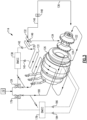
Figure 2 is a schematic illustration of an example compressor cooling arrangement. -
Figure 3 is a schematic illustration of another example compressor cooling arrangement. -
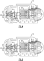
Figure 4 illustrates a view of an example compressor in a first mode. -
Figure 5 illustrates a view of an example compressor in a second mode. -
Figure 1 schematically illustrates arefrigerant cooling system 10. Therefrigerant system 10 includes a main refrigerant loop, or circuit, 12 in communication with a compressor ormultiple compressors 14, acondenser 16, anevaporator 18, and anexpansion device 20. Thisrefrigerant system 10 may be used in a chiller or heat pump, for example. Notably, while a particular example of therefrigerant system 10 is shown, this application extends to other refrigerant system configurations. For instance, themain refrigerant loop 12 can include an economizer downstream of thecondenser 16 and upstream of theexpansion device 20. Therefrigerant cooling system 10 may be an air condition system, for example. -
Figure 2 schematically illustrates anexample compressor 14. Theexample compressor 14 is a two-stage compressor. Afirst impeller 22 is upstream of asecond impeller 24. Theexample compressor 14 is a two stage centrifugal compressor. Other multiple-stage compressors may be utilized in other examples. In some examples, one stage includes an impeller and shroud arrangement, and another stage includes an alternative arrangement. Theimpellers motor 26. - The
compressor 14 may be a split cooling compressor. Afirst cooling line 30 draws refrigerant from the main refrigerant loop 12 (shown inFigure 1 ) for the power electronics, such as an insulated-gate bipolar transistor (IGBT) and a silicon controlled rectifier (SCR), for example. In the illustrated example, thecooling line 30 has a firstheat exchanging portion 31 for cooling an IGBT and a secondheat exchanging portion 35 for cooling an SCR. Asecond cooling line 80 from themain refrigerant loop 12 cools themotor 26, for example. Afirst solenoid 29 may be in communication with afirst controller 38 to control the fluid entering thefirst cooling line 30. Asecond solenoid 79 may be in communication with a second controller 78 to control the fluid entering thesecond cooling line 80. Although illustrated as twocontrollers 38, 78, it should be understood that a single controller may be used for bothcooling lines controller 38, 78 may be a Bearing Motor compressor controller (BMCC). The controller 78 may be in communication withsensors cooling line 80, for example. In the illustrated example, afirst temperature sensor 84 provides a temperature at the motor windings and asecond temperature sensor 86 provides a temperature at the motor cavity. - The
cooling line 30 returns the refrigerant to themain refrigerant loop 12 near thecompressor 14. In this example, thecooling line 30 is selectable to return the refrigerant to one of at least two places at ajuncture 32. Thecooling line 30 is configured in a first mode or a second mode. In the first mode, the coolingline 30 is configured to return refrigerant via afirst line 34 that dumps refrigerant between the first andsecond impellers line 30 is configured to return refrigerant via asecond line 36 upstream of thefirst impeller 22. Thespot 36 may be the evaporator 18 or suction side of thecompressor 14 - The first and second modes may be selected manually or automatically. The first mode may be used for regular comfort cooling applications, while the second mode may be used for high SST cooling applications, such as data centers. In some examples, the
controller 38 is used to switch between the first and second modes. Thecontroller 38 may be in communication withsensors line 30, for example. In the illustrated example, afirst temperature sensor 40 provides a temperature at the IGBT and asecond temperature sensor 42 provides a temperature at the SCR. A directionalflow control valve 33 is used to switch between the first mode and the second mode. - The
controller 38 may monitor the suction pressure of thecompressor 14, in some examples. In some examples, thecontroller 38 will direct thevalve 33 to return the refrigerant via thesecond line 36 if the suction pressure of thecompressor 14 is above a preset value. This is the second mode with a suction return. If the suction pressure is below the preset value, thevalve 33 will return the refrigerant via thefirst line 34. This is the first mode inter-stage return. The first mode may be the default mode, for example. - The
controller 38 may monitor the pressure difference in the cooling line and thetemperature sensors controller 38 can direct thevalve 33 to return to thesecond line 36. If the pressure difference is enough to keep the temperature set points, it can direct the return to 34 to increase the total system efficiency. -
Figure 3 schematically illustrates anotherexample compressor 114. To the extent not otherwise described or shown, thecompressor 114 corresponds to thecompressor 14 ofFigure 2 , with like parts having reference numerals preappended with a "1." - In this example, the
first line 134 may be blocked off by a threadedplug 149, for example. The threadedplug 149 may be arranged in a silicon controlled rectifier (SCR)heat sink 135. In this example, thesecond line 136 is aninternal channel 146 with acustomer connection plug 148. Acustomer connection plug 148 may be used to control flow through thesecond line 136. In one example, thecustomer connection plug 148 may be accessed external to a compressor housing, such that the customer may manually change between the first and second modes. Thecustomer connection plug 148 may be used in combination with a separate threadedplug 149, or without a separate plug. - In high SST applications, such as data centers cooling, the cooling line pressure difference may be lower than normal comfort cooling. Known cooling lines return refrigerant between the first and second compressor stages. However, for high SST applications, this known arrangement may not provide even cooling due to low pressure difference. The disclosed arrangement of returning refrigerant to the suction side may improve cooling for high SST applications, since the suction side has a lower temperature and pressure. The disclosed arrangement may also permit the cooling return to be selected based on a particular application or operating condition. Thus, the pressure difference and saturated temperature of the refrigerant are selectable. The disclosed arrangement may be used for data center cooling, for example. This arrangement may help prevent overheating and/or too much liquid in high SST applications.
-
Figures 4 and 5 illustrate one example of manually switching between the first and second modes.Figure 4 shows a view of anexample compressor 14 in the first mode. In this example, ashort plug 50 is used to block off the second line 36 (shown inFigure 2 ). Theshort plug 50 is thus used in the first mode, so the refrigerant is returned between the first and second stages via thefirst line 34. Theshort plug 50 may be a threaded plug, for example. -
Figure 5 shows a view of anexample compressor 14 in the second mode. In this example, along plug 52 is used to block off the first line 34 (shown inFigure 2 ). Thelong plug 52 is thus used in the second mode, so the refrigerant is returned to the suction upstream of the first stage. Thelong plug 52 may be a threaded plug, for example. - In some examples, the
compressor 14 may be shipped to a customer with both ashort plug 50 and along plug 52. The customer can then decide whether to use thecompressor 14 with the short orlong plug second plugs compressor 14. Theplugs single compressor 14 operable in two modes. In some examples, the customer decides which mode to use based on the application, and does not change between the first and second modes after thecompressor 14 is installed. - Although plugs are shown and described, other methods of switching flow between the first and second lines may fall within the scope of this disclosure. For example, in one example, the
compressor 14 may start with a plug in place in the first mode, then the plug may be removed and a return pipe connected to the suction for the second mode. In this example, a plug may not be used when thecompressor 14 is in the second mode.
Claims (14)
- A refrigerant compressor (14), comprising:a first stage (22) and a second stage (24) downstream of the first stage (22); characterized bya cooling line (30) configured to cool power electronics, the cooling line (30) configured to be switched between a first mode and a second mode, wherein the first mode is configured to dump refrigerant between the first stage (22) and the second stage (24), and the second mode is configured to dump refrigerant upstream of the first stage (22),wherein the cooling line (30) is configured to draw refrigerant from a main refrigerant loop (12).
- The refrigerant compressor (14) of claim 1, wherein the compressor (14) is a centrifugal compressor (14) and the first stage (22) comprises a first impeller and the second stage (24) comprises a second impeller.
- The refrigerant compressor (14) of claim 1, comprising a controller (38) configured to switch between the first and second modes automatically in response to an input from a sensor (40, 42).
- The refrigerant compressor (14) of claim 3, wherein the controller (38) is configured to monitor a suction pressure of the compressor (14), and the controller (38) is configured to automatically switch to the second mode when the suction pressure is above a predetermined threshold.
- The refrigerant compressor (14) of claim 3, wherein the controller is configured to automatically direct the return of the cooling flow in a real time manner based on operating conditions.
- The refrigerant compressor (14) of claim 1, wherein the cooling line (30) is configured to be switched between the first mode and the second mode by inserting a plug (50, 52) along the cooling line (30).
- The refrigerant compressor (14) of claim 6, wherein the compressor (14) comprises a housing, and the plug (50, 52) is accessible external to the housing.
- The refrigerant compressor (14) of claim 6, wherein the plug (50, 52) is a threaded plug.
- The refrigerant compressor (14) of claim 1, comprising a directional flow control valve (33) configured to switch between the first mode and the second mode.
- The refrigerant compressor (14) of claim 1, wherein the second mode is used for high saturated suction temperature (SST), or low pressure difference cooling applications.
- A refrigerant system (10), comprising:
a main refrigerant loop (12) in communication with a condenser (16), an evaporator (18), and a compressor (14) according to claim 1 - The refrigerant system (10) of claim 11, wherein the power electronics comprises a silicon controlled rectifier, and the cooling line (30) comprises a heat exchanger arranged to cool the silicon controlled rectifier, optionally wherein a first plug (50, 52) is arranged in the heat exchanger.
- The refrigerant system (10) of claim 11, wherein the cooling line (30) is configured to be switched between the first mode and the second mode by inserting a plug (50, 52) along the cooling line (30), optionally wherein the compressor (16) is arranged in a housing, and the plug (50, 52) is accessible external to the housing.
- The refrigerant system (10) of claim 11, wherein a controller (38) is configured to switch between the first and second modes automatically in response to an input from a sensor (40, 42),or wherein the controller (38) is set to direct the return of the cooling flow based on applications of normal comfort cooling or high SST cooling,or wherein the controller (38) is configured to direct the return of the cooling flow in a real time manner based on operating conditions,or wherein the controller (38) is configured to monitor a suction pressure of the compressor, and the controller (38) is configured to automatically switch to the second mode when the suction pressure is above a predetermined threshold.
Applications Claiming Priority (2)
| Application Number | Priority Date | Filing Date | Title |
|---|---|---|---|
| US201962881550P | 2019-08-01 | 2019-08-01 | |
| PCT/US2020/044570 WO2021022192A1 (en) | 2019-08-01 | 2020-07-31 | Power electronics cooling arrangement |
Publications (3)
| Publication Number | Publication Date |
|---|---|
| EP4007871A1 EP4007871A1 (en) | 2022-06-08 |
| EP4007871A4 EP4007871A4 (en) | 2023-08-16 |
| EP4007871B1 true EP4007871B1 (en) | 2025-02-19 |
Family
ID=74230567
Family Applications (1)
| Application Number | Title | Priority Date | Filing Date |
|---|---|---|---|
| EP20847063.3A Active EP4007871B1 (en) | 2019-08-01 | 2020-07-31 | Power electronics cooling arrangement |
Country Status (4)
| Country | Link |
|---|---|
| US (1) | US11994136B2 (en) |
| EP (1) | EP4007871B1 (en) |
| CN (1) | CN114286916B (en) |
| WO (1) | WO2021022192A1 (en) |
Families Citing this family (2)
| Publication number | Priority date | Publication date | Assignee | Title |
|---|---|---|---|---|
| US12526968B2 (en) | 2022-01-06 | 2026-01-13 | Carrier Corporation | Heatsink for power electronics cooling |
| CN116437624A (en) | 2022-01-11 | 2023-07-14 | 开利公司 | mechanical enclosure |
Family Cites Families (16)
| Publication number | Priority date | Publication date | Assignee | Title |
|---|---|---|---|---|
| US3253646A (en) * | 1964-04-08 | 1966-05-31 | Udylite Corp | Cooling system for power supply apparatus |
| JPS5223402B2 (en) * | 1973-10-12 | 1977-06-24 | ||
| US5350039A (en) * | 1993-02-25 | 1994-09-27 | Nartron Corporation | Low capacity centrifugal refrigeration compressor |
| US6189335B1 (en) * | 1998-02-06 | 2001-02-20 | Sanyo Electric Co., Ltd. | Multi-stage compressing refrigeration device and refrigerator using the device |
| US6176092B1 (en) * | 1998-10-09 | 2001-01-23 | American Standard Inc. | Oil-free liquid chiller |
| DE10128307B4 (en) * | 2001-06-12 | 2004-03-18 | Siemens Ag | air conditioning |
| US7003971B2 (en) * | 2004-04-12 | 2006-02-28 | York International Corporation | Electronic component cooling system for an air-cooled chiller |
| US8322155B2 (en) | 2006-08-15 | 2012-12-04 | American Power Conversion Corporation | Method and apparatus for cooling |
| WO2008140454A1 (en) * | 2007-05-14 | 2008-11-20 | Carrier Corporation | Refrigerant vapor compression system with flash tank economizer |
| JP4814167B2 (en) * | 2007-07-25 | 2011-11-16 | 三菱重工業株式会社 | Multistage compressor |
| US20110023513A1 (en) * | 2009-07-28 | 2011-02-03 | Hamilton Sundstrand Corporation | Expansion valve for a refrigerant system |
| US9316424B2 (en) | 2011-04-19 | 2016-04-19 | Liebert Corporation | Multi-stage cooling system with tandem compressors and optimized control of sensible cooling and dehumidification |
| JP5821756B2 (en) * | 2011-04-21 | 2015-11-24 | 株式会社デンソー | Refrigeration cycle equipment |
| US8950201B2 (en) * | 2012-03-30 | 2015-02-10 | Trane International Inc. | System and method for cooling power electronics using heat sinks |
| KR102128584B1 (en) * | 2013-09-16 | 2020-06-30 | 엘지전자 주식회사 | An air conditioner |
| DE102017107602B3 (en) * | 2017-04-10 | 2018-09-20 | Gardner Denver Deutschland Gmbh | Compressor system with internal air-water cooling |
-
2020
- 2020-07-31 US US17/618,910 patent/US11994136B2/en active Active
- 2020-07-31 CN CN202080053518.5A patent/CN114286916B/en active Active
- 2020-07-31 WO PCT/US2020/044570 patent/WO2021022192A1/en not_active Ceased
- 2020-07-31 EP EP20847063.3A patent/EP4007871B1/en active Active
Also Published As
| Publication number | Publication date |
|---|---|
| CN114286916A (en) | 2022-04-05 |
| WO2021022192A1 (en) | 2021-02-04 |
| EP4007871A4 (en) | 2023-08-16 |
| CN114286916B (en) | 2024-07-30 |
| US11994136B2 (en) | 2024-05-28 |
| US20220252073A1 (en) | 2022-08-11 |
| EP4007871A1 (en) | 2022-06-08 |
Similar Documents
| Publication | Publication Date | Title |
|---|---|---|
| US10274233B2 (en) | Refrigerant cooling and lubrication system with refrigerant source access from an evaporator | |
| EP2979043B1 (en) | Compressor | |
| KR101602741B1 (en) | Constant temperature liquid circulating device and operation method thereof | |
| EP2837900B1 (en) | Air-conditioning device | |
| EP3348932A1 (en) | Refrigeration cycle apparatus | |
| US11994136B2 (en) | Power electronics cooling arrangement | |
| US12018867B2 (en) | Refrigeration apparatus | |
| JP2014163624A (en) | Turbo refrigerator | |
| JP2016205773A (en) | Air conditioner | |
| JP5854882B2 (en) | Chilling unit | |
| JP6497582B2 (en) | Refrigerator unit | |
| CN106796056A (en) | Freezing cycle device | |
| JP6069179B2 (en) | Turbo refrigerator | |
| JP6295121B2 (en) | Turbo refrigerator | |
| JP2017172923A (en) | Refrigerating device | |
| US20250305734A1 (en) | Valve arrangement for refrigerant compressor | |
| JP6617862B2 (en) | refrigerator | |
| JP2017201216A (en) | Turbo refrigerator | |
| EP3745047A1 (en) | Refrigeration cycle device | |
| WO2007069279A1 (en) | Energy saving chiller |
Legal Events
| Date | Code | Title | Description |
|---|---|---|---|
| STAA | Information on the status of an ep patent application or granted ep patent |
Free format text: STATUS: THE INTERNATIONAL PUBLICATION HAS BEEN MADE |
|
| PUAI | Public reference made under article 153(3) epc to a published international application that has entered the european phase |
Free format text: ORIGINAL CODE: 0009012 |
|
| STAA | Information on the status of an ep patent application or granted ep patent |
Free format text: STATUS: REQUEST FOR EXAMINATION WAS MADE |
|
| 17P | Request for examination filed |
Effective date: 20220111 |
|
| AK | Designated contracting states |
Kind code of ref document: A1 Designated state(s): AL AT BE BG CH CY CZ DE DK EE ES FI FR GB GR HR HU IE IS IT LI LT LU LV MC MK MT NL NO PL PT RO RS SE SI SK SM TR |
|
| DAV | Request for validation of the european patent (deleted) | ||
| DAX | Request for extension of the european patent (deleted) | ||
| A4 | Supplementary search report drawn up and despatched |
Effective date: 20230714 |
|
| RIC1 | Information provided on ipc code assigned before grant |
Ipc: H02K 11/25 20160101ALI20230710BHEP Ipc: H02K 9/10 20060101ALI20230710BHEP Ipc: F25B 49/02 20060101ALI20230710BHEP Ipc: F04D 27/02 20060101ALI20230710BHEP Ipc: F04D 25/06 20060101ALI20230710BHEP Ipc: F04D 17/12 20060101ALI20230710BHEP Ipc: H05K 7/20 20060101ALI20230710BHEP Ipc: H02K 9/00 20060101ALI20230710BHEP Ipc: F25B 31/00 20060101ALI20230710BHEP Ipc: F25B 1/10 20060101ALI20230710BHEP Ipc: F04D 29/58 20060101ALI20230710BHEP Ipc: F24F 1/24 20110101AFI20230710BHEP |
|
| P01 | Opt-out of the competence of the unified patent court (upc) registered |
Effective date: 20230713 |
|
| GRAP | Despatch of communication of intention to grant a patent |
Free format text: ORIGINAL CODE: EPIDOSNIGR1 |
|
| STAA | Information on the status of an ep patent application or granted ep patent |
Free format text: STATUS: GRANT OF PATENT IS INTENDED |
|
| INTG | Intention to grant announced |
Effective date: 20240918 |
|
| GRAS | Grant fee paid |
Free format text: ORIGINAL CODE: EPIDOSNIGR3 |
|
| GRAA | (expected) grant |
Free format text: ORIGINAL CODE: 0009210 |
|
| STAA | Information on the status of an ep patent application or granted ep patent |
Free format text: STATUS: THE PATENT HAS BEEN GRANTED |
|
| AK | Designated contracting states |
Kind code of ref document: B1 Designated state(s): AL AT BE BG CH CY CZ DE DK EE ES FI FR GB GR HR HU IE IS IT LI LT LU LV MC MK MT NL NO PL PT RO RS SE SI SK SM TR |
|
| REG | Reference to a national code |
Ref country code: GB Ref legal event code: FG4D |
|
| REG | Reference to a national code |
Ref country code: CH Ref legal event code: EP |
|
| REG | Reference to a national code |
Ref country code: IE Ref legal event code: FG4D |
|
| REG | Reference to a national code |
Ref country code: DE Ref legal event code: R096 Ref document number: 602020046488 Country of ref document: DE |
|
| REG | Reference to a national code |
Ref country code: NL Ref legal event code: MP Effective date: 20250219 |
|
| PG25 | Lapsed in a contracting state [announced via postgrant information from national office to epo] |
Ref country code: RS Free format text: LAPSE BECAUSE OF FAILURE TO SUBMIT A TRANSLATION OF THE DESCRIPTION OR TO PAY THE FEE WITHIN THE PRESCRIBED TIME-LIMIT Effective date: 20250519 |
|
| PG25 | Lapsed in a contracting state [announced via postgrant information from national office to epo] |
Ref country code: FI Free format text: LAPSE BECAUSE OF FAILURE TO SUBMIT A TRANSLATION OF THE DESCRIPTION OR TO PAY THE FEE WITHIN THE PRESCRIBED TIME-LIMIT Effective date: 20250219 |
|
| PG25 | Lapsed in a contracting state [announced via postgrant information from national office to epo] |
Ref country code: PL Free format text: LAPSE BECAUSE OF FAILURE TO SUBMIT A TRANSLATION OF THE DESCRIPTION OR TO PAY THE FEE WITHIN THE PRESCRIBED TIME-LIMIT Effective date: 20250219 |
|
| PG25 | Lapsed in a contracting state [announced via postgrant information from national office to epo] |
Ref country code: ES Free format text: LAPSE BECAUSE OF FAILURE TO SUBMIT A TRANSLATION OF THE DESCRIPTION OR TO PAY THE FEE WITHIN THE PRESCRIBED TIME-LIMIT Effective date: 20250219 |
|
| PGFP | Annual fee paid to national office [announced via postgrant information from national office to epo] |
Ref country code: GB Payment date: 20250612 Year of fee payment: 6 |
|
| REG | Reference to a national code |
Ref country code: LT Ref legal event code: MG9D |
|
| PG25 | Lapsed in a contracting state [announced via postgrant information from national office to epo] |
Ref country code: NO Free format text: LAPSE BECAUSE OF FAILURE TO SUBMIT A TRANSLATION OF THE DESCRIPTION OR TO PAY THE FEE WITHIN THE PRESCRIBED TIME-LIMIT Effective date: 20250519 Ref country code: IS Free format text: LAPSE BECAUSE OF FAILURE TO SUBMIT A TRANSLATION OF THE DESCRIPTION OR TO PAY THE FEE WITHIN THE PRESCRIBED TIME-LIMIT Effective date: 20250619 |
|
| PG25 | Lapsed in a contracting state [announced via postgrant information from national office to epo] |
Ref country code: NL Free format text: LAPSE BECAUSE OF FAILURE TO SUBMIT A TRANSLATION OF THE DESCRIPTION OR TO PAY THE FEE WITHIN THE PRESCRIBED TIME-LIMIT Effective date: 20250219 |
|
| PG25 | Lapsed in a contracting state [announced via postgrant information from national office to epo] |
Ref country code: HR Free format text: LAPSE BECAUSE OF FAILURE TO SUBMIT A TRANSLATION OF THE DESCRIPTION OR TO PAY THE FEE WITHIN THE PRESCRIBED TIME-LIMIT Effective date: 20250219 |
|
| PG25 | Lapsed in a contracting state [announced via postgrant information from national office to epo] |
Ref country code: PT Free format text: LAPSE BECAUSE OF FAILURE TO SUBMIT A TRANSLATION OF THE DESCRIPTION OR TO PAY THE FEE WITHIN THE PRESCRIBED TIME-LIMIT Effective date: 20250620 Ref country code: LV Free format text: LAPSE BECAUSE OF FAILURE TO SUBMIT A TRANSLATION OF THE DESCRIPTION OR TO PAY THE FEE WITHIN THE PRESCRIBED TIME-LIMIT Effective date: 20250219 |
|
| PGFP | Annual fee paid to national office [announced via postgrant information from national office to epo] |
Ref country code: FR Payment date: 20250610 Year of fee payment: 6 |
|
| PG25 | Lapsed in a contracting state [announced via postgrant information from national office to epo] |
Ref country code: GR Free format text: LAPSE BECAUSE OF FAILURE TO SUBMIT A TRANSLATION OF THE DESCRIPTION OR TO PAY THE FEE WITHIN THE PRESCRIBED TIME-LIMIT Effective date: 20250520 Ref country code: BG Free format text: LAPSE BECAUSE OF FAILURE TO SUBMIT A TRANSLATION OF THE DESCRIPTION OR TO PAY THE FEE WITHIN THE PRESCRIBED TIME-LIMIT Effective date: 20250219 |
|
| REG | Reference to a national code |
Ref country code: AT Ref legal event code: MK05 Ref document number: 1768576 Country of ref document: AT Kind code of ref document: T Effective date: 20250219 |
|
| PG25 | Lapsed in a contracting state [announced via postgrant information from national office to epo] |
Ref country code: SE Free format text: LAPSE BECAUSE OF FAILURE TO SUBMIT A TRANSLATION OF THE DESCRIPTION OR TO PAY THE FEE WITHIN THE PRESCRIBED TIME-LIMIT Effective date: 20250219 |
|
| PG25 | Lapsed in a contracting state [announced via postgrant information from national office to epo] |
Ref country code: SM Free format text: LAPSE BECAUSE OF FAILURE TO SUBMIT A TRANSLATION OF THE DESCRIPTION OR TO PAY THE FEE WITHIN THE PRESCRIBED TIME-LIMIT Effective date: 20250219 |
|
| PG25 | Lapsed in a contracting state [announced via postgrant information from national office to epo] |
Ref country code: DK Free format text: LAPSE BECAUSE OF FAILURE TO SUBMIT A TRANSLATION OF THE DESCRIPTION OR TO PAY THE FEE WITHIN THE PRESCRIBED TIME-LIMIT Effective date: 20250219 |
|
| PGFP | Annual fee paid to national office [announced via postgrant information from national office to epo] |
Ref country code: DE Payment date: 20250604 Year of fee payment: 6 |
|
| PG25 | Lapsed in a contracting state [announced via postgrant information from national office to epo] |
Ref country code: IT Free format text: LAPSE BECAUSE OF FAILURE TO SUBMIT A TRANSLATION OF THE DESCRIPTION OR TO PAY THE FEE WITHIN THE PRESCRIBED TIME-LIMIT Effective date: 20250219 |
|
| PG25 | Lapsed in a contracting state [announced via postgrant information from national office to epo] |
Ref country code: AT Free format text: LAPSE BECAUSE OF FAILURE TO SUBMIT A TRANSLATION OF THE DESCRIPTION OR TO PAY THE FEE WITHIN THE PRESCRIBED TIME-LIMIT Effective date: 20250219 |
|
| PG25 | Lapsed in a contracting state [announced via postgrant information from national office to epo] |
Ref country code: EE Free format text: LAPSE BECAUSE OF FAILURE TO SUBMIT A TRANSLATION OF THE DESCRIPTION OR TO PAY THE FEE WITHIN THE PRESCRIBED TIME-LIMIT Effective date: 20250219 Ref country code: CZ Free format text: LAPSE BECAUSE OF FAILURE TO SUBMIT A TRANSLATION OF THE DESCRIPTION OR TO PAY THE FEE WITHIN THE PRESCRIBED TIME-LIMIT Effective date: 20250219 |
|
| PG25 | Lapsed in a contracting state [announced via postgrant information from national office to epo] |
Ref country code: RO Free format text: LAPSE BECAUSE OF FAILURE TO SUBMIT A TRANSLATION OF THE DESCRIPTION OR TO PAY THE FEE WITHIN THE PRESCRIBED TIME-LIMIT Effective date: 20250219 |
|
| PG25 | Lapsed in a contracting state [announced via postgrant information from national office to epo] |
Ref country code: SK Free format text: LAPSE BECAUSE OF FAILURE TO SUBMIT A TRANSLATION OF THE DESCRIPTION OR TO PAY THE FEE WITHIN THE PRESCRIBED TIME-LIMIT Effective date: 20250219 |
|
| REG | Reference to a national code |
Ref country code: DE Ref legal event code: R097 Ref document number: 602020046488 Country of ref document: DE |
|
| PLBE | No opposition filed within time limit |
Free format text: ORIGINAL CODE: 0009261 |
|
| STAA | Information on the status of an ep patent application or granted ep patent |
Free format text: STATUS: NO OPPOSITION FILED WITHIN TIME LIMIT |
|
| REG | Reference to a national code |
Ref country code: CH Ref legal event code: L10 Free format text: ST27 STATUS EVENT CODE: U-0-0-L10-L00 (AS PROVIDED BY THE NATIONAL OFFICE) Effective date: 20251231 |
|
| 26N | No opposition filed |
Effective date: 20251120 |
|
| REG | Reference to a national code |
Ref country code: CH Ref legal event code: H13 Free format text: ST27 STATUS EVENT CODE: U-0-0-H10-H13 (AS PROVIDED BY THE NATIONAL OFFICE) Effective date: 20260224 |
|
| PG25 | Lapsed in a contracting state [announced via postgrant information from national office to epo] |
Ref country code: LU Free format text: LAPSE BECAUSE OF NON-PAYMENT OF DUE FEES Effective date: 20250731 |
|
| REG | Reference to a national code |
Ref country code: BE Ref legal event code: MM Effective date: 20250731 |
|
| PG25 | Lapsed in a contracting state [announced via postgrant information from national office to epo] |
Ref country code: BE Free format text: LAPSE BECAUSE OF NON-PAYMENT OF DUE FEES Effective date: 20250731 |
|
| PG25 | Lapsed in a contracting state [announced via postgrant information from national office to epo] |
Ref country code: CH Free format text: LAPSE BECAUSE OF NON-PAYMENT OF DUE FEES Effective date: 20250731 |