EP4007465A1 - Operation panel for power conversion device and power conversion device - Google Patents
Operation panel for power conversion device and power conversion device Download PDFInfo
- Publication number
- EP4007465A1 EP4007465A1 EP21199579.0A EP21199579A EP4007465A1 EP 4007465 A1 EP4007465 A1 EP 4007465A1 EP 21199579 A EP21199579 A EP 21199579A EP 4007465 A1 EP4007465 A1 EP 4007465A1
- Authority
- EP
- European Patent Office
- Prior art keywords
- operation panel
- battery
- power conversion
- conversion device
- button battery
- Prior art date
- Legal status (The legal status is an assumption and is not a legal conclusion. Google has not performed a legal analysis and makes no representation as to the accuracy of the status listed.)
- Granted
Links
Images






Classifications
-
- H—ELECTRICITY
- H05—ELECTRIC TECHNIQUES NOT OTHERWISE PROVIDED FOR
- H05K—PRINTED CIRCUITS; CASINGS OR CONSTRUCTIONAL DETAILS OF ELECTRIC APPARATUS; MANUFACTURE OF ASSEMBLAGES OF ELECTRICAL COMPONENTS
- H05K5/00—Casings, cabinets or drawers for electric apparatus
- H05K5/02—Details
- H05K5/0256—Details of interchangeable modules or receptacles therefor, e.g. cartridge mechanisms
- H05K5/0286—Receptacles therefor, e.g. card slots, module sockets, card groundings
-
- H—ELECTRICITY
- H02—GENERATION; CONVERSION OR DISTRIBUTION OF ELECTRIC POWER
- H02M—APPARATUS FOR CONVERSION BETWEEN AC AND AC, BETWEEN AC AND DC, OR BETWEEN DC AND DC, AND FOR USE WITH MAINS OR SIMILAR POWER SUPPLY SYSTEMS; CONVERSION OF DC OR AC INPUT POWER INTO SURGE OUTPUT POWER; CONTROL OR REGULATION THEREOF
- H02M1/00—Details of apparatus for conversion
-
- H—ELECTRICITY
- H05—ELECTRIC TECHNIQUES NOT OTHERWISE PROVIDED FOR
- H05K—PRINTED CIRCUITS; CASINGS OR CONSTRUCTIONAL DETAILS OF ELECTRIC APPARATUS; MANUFACTURE OF ASSEMBLAGES OF ELECTRICAL COMPONENTS
- H05K5/00—Casings, cabinets or drawers for electric apparatus
- H05K5/02—Details
- H05K5/03—Covers
Definitions
- the present invention relates to an operation panel for a power conversion device and a power conversion device, and more particularly to an operation panel for a power conversion device and a power conversion device provided with an operation unit that operates a power conversion device main body portion.
- an operation panel for a power conversion device provided with an operation unit (switch) that operates a power conversion device main body portion.
- Such an operation panel for a power conversion device is disclosed in, for example, Japanese Unexamined Patent Application, First Publication No. 2005-117733 ( JP-A-2005-117733 ).
- JP-A-2005-117733 discloses an operation panel for a power conversion device including a switch for selecting an operation method of a power conversion device main body portion, a switch for selecting an output frequency setting of the power conversion device main body portion, and a connector to connect to the power conversion device main body portion.
- the functions required for the operation panel for a power conversion device have been increased in recent years.
- the functions required for the operation panel include enabling operation even when power supply from the power conversion device main body portion is shut down, in addition to enabling communication with an external device. Therefore, there is a demand for an operation panel in which a button battery is mounted as an auxiliary power source for the operation panel when the power supply is shut down and the button battery can be replaced.
- the operation panel for a power conversion device in the related art as described in JP-A-2005-117733 the operation panel is provided with an operation unit (switch) that operates the power conversion device main body portion. Therefore, when the button battery is mounted on the operation unit side in a replaceable manner as the auxiliary power source, a space on the operation unit side becomes narrow and thus it is impossible to provide a communication connector or the like for communicating with an external device on the operation unit side. Since a size of the operation panel main body is determined by the main body portion of the power conversion device to which the operation panel is connected, the size of the operation panel main body cannot be easily changed. Therefore, it is difficult to increase a printed circuit board to implement the communication connector or the like. As a result, there is a demand for an operation panel for a power conversion device and a power conversion device capable of suppressing the narrowing of the space on the operation unit side while mounting the button battery for supplying the power to the operation panel in a replaceable manner.
- the present invention has been made to solve the above-mentioned problems, and one object of the present invention is to provide a demand for an operation panel for a power conversion device and a power conversion device capable of suppressing narrowing of a space on an operation unit side while mounting a button battery for supplying power to an operation panel in a replaceable manner.
- an operation panel for a power conversion device includes an operation panel board provided with operation units that operate a power conversion device main body portion on a front side, a first terminal and a second terminal provided corresponding to a button battery for supplying power to the operation panel board on a back surface of the operation panel board, a rear cover including a battery positioning portion that positions the button battery with respect to the first terminal and the second terminal and an opening portion provided such that the battery positioning portion is exposed, which is disposed so as to cover the back surface of the operation panel board, and a battery cover which is configured to be attached to and detached from the rear cover and provided so as to cover the opening portion.
- the operation unit that operates the power conversion device main body portion is provided on the front side of the operation panel board, as described above.
- the first terminal and the second terminal are provided on the back surface of the operation panel board corresponding to the button battery. Accordingly, since the button battery can be mounted on the back surface of the operation panel board provided with the first terminal and the second terminal, it is possible to suppress narrowing of a space on an operation unit side of the operation panel, unlike the case where the button battery is mounted on the front side of the operation panel board provided with the operation unit.
- the battery cover configured to be attached to and detached from the rear cover covers the opening portion provided such that the battery positioning portion is exposed.
- buttons battery replacement button battery
- the battery positioning portion that positions the button battery by detaching the battery cover.
- the operation panel main body is detachably attached to the power conversion device main body portion.
- the button battery replace button battery
- the operation panel for a power conversion device preferably, further includes a card slot portion for inserting a memory card, which is provided on the back surface of the operation panel board.
- the operation panel board is provided with a stroke area for sliding the memory card to insert the card into the card slot portion and remove the card from the card slot portion.
- the opening portion is provided in the rear cover such that the battery positioning portion and the stroke area are exposed.
- a function required for the operation panel for a power conversion device includes enabling mounting of the memory card for storing a communication setting, a communication log, or the like with an external device.
- the card slot portion for inserting the memory card is provided on the back surface of the operation panel board, it is possible to store the communication setting, the communication log, or the like with the device outside the power conversion device in the memory card by mounting the memory card on the back surface of the operation panel board.
- the operation panel board is provided with the stroke area for sliding the memory card to insert the card into the card slot portion and remove the card from the card slot portion, it is possible to easily insert the card into the card slot portion and remove the card from the card slot portion.
- the opening portion is provided in the rear cover such that the battery positioning portion and the stroke area are exposed, it is possible to provide the battery cover provided so as to cover the opening portion in common with respect to the battery positioning portion and the stroke area. As a result, it is possible to suppress an increase in the number of components and a complicated device configuration.
- the stroke area is provided between the card slot portion and the battery positioning portion.
- the battery positioning portion is configured to be flexurally deformable at the time of the attachment and detachment of the button battery.
- the rear cover further includes a flexure regulating portion that regulates a flexural deformation amount of the battery positioning portion at the time of the attachment and detachment of the button battery.
- the battery positioning portion includes a snap-fit portion that is provided along an outer peripheral surface of the button battery and is flexurally deformable at the time of the attachment and detachment of the button battery.
- the snap-fit portion is provided with a positioning projection portion that projects on a side where the button battery is disposed and on a side where the second terminal is disposed, in order to position a position of the button battery with respect to the second terminal.
- the snap-fit portion provided along the outer peripheral surface of the button battery is provided with the positioning projection portion that projects on the side where the button battery is disposed and on the side where the second terminal is disposed. Therefore, it is possible to press the button battery attached to the snap-fit portion toward the second terminal side. As a result, it is possible to reliably bring the button battery and the second terminal into contact with each other at the time of the attachment of the button battery.
- the snap-fit portion includes a pair of arm portions having an arc shape, which are elastically deformable, provided in an arc shape along the outer peripheral surface of the button battery. Tip ends of the pair of arm portions having the arc shape are provided on a side where the stroke area is disposed with respect to the button battery.
- the first terminal is disposed on a tip end side of the pair of arm portions having the arc shape from a central portion of the position where the button battery is disposed, in an area surrounded by the pair of arm portions having the arc shape.
- the button battery is provided with a negative pole on one side surface, a positive pole provided on the other side surface, and a positive pole also provided on the outer peripheral surface of the button battery.
- the positive and negative poles of the button battery may be short-circuited due to contact of the positive pole provided on the outer peripheral surface of the button battery and the negative pole provided on one side surface of the button battery with the terminal provided on the operation panel board at the same time.
- the first terminal is disposed on the tip end side of the pair of arm portions having the arc shape from the central portion of the position where the button battery is disposed.
- the first terminal it is possible to dispose the first terminal at a position separated from the positive pole provided on the outer peripheral surface of the button battery, as compared with the case where the first terminal is disposed at the central portion of the position where the button battery is disposed, as described above. As a result, it is possible to prevent the positive and negative poles of the button battery from being short-circuited due to the contact of both the positive and negative poles of the button battery with the first terminal at the time of the attachment and detachment of the button battery (replacement of the button battery).
- the second terminal is disposed on an outer peripheral surface side of the button battery and is configured to be flexurally deformable.
- the rear cover further includes a position regulating portion that regulates a position of the outer peripheral surface of the button battery with respect to the second terminal in order to regulate a flexural deformation amount of the second terminal.
- a plurality of the second terminals are provided along the outer peripheral surface of the button battery.
- the plurality of second terminals are provided along the outer peripheral surface of the button battery, it is possible to bring any second terminal into contact with the button battery even in a case where the attachment position of the button battery is displaced on the operation panel board, unlike a case where only one second terminal is provided.
- the rear cover further includes an intrusion prevention portion that prevents the memory card from intruding between the rear cover and the operation panel board, which is provided along an outer edge of the stroke area so as to project toward the operation panel board side.
- the battery cover includes a projection portion that projects toward a first terminal side provided on the operation panel board in a state of being attached to the rear cover to press the button battery toward the first terminal side.
- the power conversion device main body portion is accommodated and a rear side of an operation panel main body is configured to be attached to a control panel that performs power control.
- the operation panel further includes a sealing member, between the rear cover and the control panel, provided on an outside of the battery cover so as to surround the battery cover.
- the battery cover is disposed at a central portion of a surface of the rear cover facing the control panel.
- the rear cover has a groove portion that is formed along an outer peripheral portion of the surface of the rear cover facing the control panel and into which the sealing member is fitted.
- the battery cover With the disposition of the battery cover near the central portion of the surface of the rear cover facing the control panel, it is possible to easily surround the battery cover with the sealing member, as compared with a case where the battery cover is provided near the outer peripheral portion of the surface of the rear cover facing the control panel. As a result, it is possible to easily prevent water from intruding between the rear cover and the battery cover.
- a power conversion device includes a power conversion device main body portion, and an operation panel that is detachably attached to the power conversion device main body portion and receives an operation on the power conversion device main body portion.
- the operation panel includes an operation panel board provided with operation units that operate the power conversion device main body portion on a front side, a first terminal and a second terminal provided corresponding to a button battery for supplying power to the operation panel board on a back surface of the operation panel board, a rear cover including a battery positioning portion that positions the button battery with respect to the first terminal and the second terminal and an opening portion provided such that the battery positioning portion is exposed, which is disposed so as to cover the back surface of the operation panel board, and a battery cover which is configured to be attached to and detached from the rear cover and provided so as to cover the opening portion.
- the operation unit that operates the power conversion device main body portion is provided on the front side of the operation panel board, as described above.
- the first terminal and the second terminal are provided on the back surface of the operation panel board corresponding to the button battery. Accordingly, since the button battery can be mounted on the back surface of the operation panel board provided with the first terminal and the second terminal, it is possible to suppress the narrowing of the space on the operation unit side, unlike the case where the button battery is mounted on the front side of the operation panel board provided with the operation unit.
- the battery cover configured to be attached to and detached from the rear cover of the operation panel is configured to cover the opening portion provided such that the battery positioning portion is exposed.
- the user can attach and detach the button battery with respect to the battery positioning portion that positions the button battery by detaching the battery cover from the operation panel in a state of being detached from the power conversion device main body portion.
- the power conversion device capable of suppressing the narrowing of the space on the operation unit side of the operation panel while mounting the button battery for supplying the power to the operation panel in a replaceable manner.
- the operation panel 101 is an example of an"operation panel for a power conversion device" in the claims.
- the power conversion device 100 includes a power conversion device main body portion 102 and the operation panel 101 that receives an operation on the power conversion device main body portion 102.
- the operation panel 101 is configured such that a rear side (Y2 direction side) of the operation panel 101 main body is attached to a control panel 110.
- the control panel 110 is configured to accommodate the power conversion device main body portion 102 and perform power control.
- the control panel 110 is configured to control the power supplied to a load (not shown) outside the control panel 110.
- An electric device other than the power conversion device main body portion 102 such as a circuit breaker, an on/off switch, a switch (push button), a display, or an electric meter, may be accommodated inside the control panel 110.
- the power conversion device 100 is, for example, an inverter device that converts AC power input from a commercial power source and outputs the converted power to the load.
- the power conversion device 100 is configured to communicate with an external device such as a personal computer (PC) .
- PC personal computer
- the operation panel 101 is a device that operates a power conversion operation by the power conversion device 100 (power conversion device main body portion 102).
- the operation panel 101 is configured to be attached to and detached from the control panel 110 that accommodates the power conversion device main body portion 102.
- the operation panel 101 is attached detachably (to be attachable and detachable) to the power conversion device main body portion 102.
- the operation panel 101 is configured such that the power is supplied from a button battery B (refer to Fig. 4 ) when the power supply is shut off, such as when the power conversion operation by the power conversion device main body portion 102 is stopped. Accordingly, the operation panel 101 is configured to maintain an operable state even when the power supply from the power conversion device main body portion 102 is shut off. That is, the operation panel 101 uses the button battery B as an auxiliary power source.
- the operation panel 101 includes a main body cover 10.
- a display 1, an operation button 2, and a terminal cover 3 are provided on a front side (Y1 direction side) of the operation panel 101.
- the display 1 is a display device that checks a state, setting, or the like of the power conversion device 100 (power conversion device main body portion 102).
- the display 1 includes a liquid crystal display or an organic EL display.
- the operation button 2 is a button for operating the power conversion device main body portion 102 (power conversion device 100).
- the operation button 2 is provided on the front side (Y1 direction side) of an operation panel board 50 (refer to Fig. 5A ) described below.
- the operation button 2 is a push button disposed so as to correspond to a plurality of switches 4 (refer to Fig. 5A ) provided on the front side (Y1 direction side) of the operation panel board 50 described below.
- the operation button 2 and the switch 4 are examples of an "operation unit" in the claims.
- the operation panel 101 is configured to receive an input operation based on the input operation by a user on a plurality of operation buttons 2. That is, the user can change the operation, setting, or the like of the power conversion device 100 (power conversion device main body portion 102) by operating the operation button 2.
- the terminal cover 3 is provided so as to cover a connector 5 (refer to Fig. 5A ) described below.
- the terminal cover 3 is configured detachably such that the connector 5 can be exposed when the connector 5 is used.
- the terminal cover 3 is configured to be elastically deformable.
- the terminal cover 3 is made of rubber, for example.
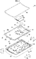
- the operation panel 101 includes a rear cover 20 and a battery cover 30.
- the rear cover 20 and the battery cover 30 are disposed on the rear side (Y2 direction side) of the operation panel 101.
- the operation panel 101 includes a sealing member 40 provided on the outside of the battery cover 30 so as to surround the battery cover 30.
- the sealing member 40 includes a waterproof packing.
- the sealing member 40 may include a potting material.
- a hole portion for fastening H1 is provided on the rear side (Y2 direction side) of the operation panel 101, as shown in Fig. 3 .
- the hole portion for fastening H1 is provided on the rear cover 20 and is a hole portion used when the operation panel 101 is fastened and fixed to the control panel 110.
- connectors 6 and 7 for communicably connecting the power conversion device main body portion 102 and the operation panel 101 (operation panel board 50) are provided, as shown in Fig. 3 .
- Each of the connectors 6 and 7 is provided so as to project from a back surface (surface on Y2 direction side) of the operation panel board 50 (refer to Fig. 4 ) toward the outside (Y2 direction side) of the operation panel 101.
- the operation panel 101 includes the operation panel board 50.
- the operation panel board 50 is a printed circuit board (PCB) in which a wiring pattern is formed by a conductor and electronic components EC such as a central processing unit (CPU) and a read only memory (ROM) or a random access memory (RAM) are mounted.
- PCB printed circuit board
- electronic components EC such as a central processing unit (CPU) and a read only memory (ROM) or a random access memory (RAM) are mounted.
- the operation panel 101 includes a negative terminal 51 and a positive terminal 52, which correspond to the button battery B for supplying the power to the operation panel board 50, provided on the back surface (surface on Y2 direction side) of the operation panel board 50.
- the negative terminal 51 is an example of a "first terminal” in the claims
- the positive terminal 52 is an example of a "second terminal” in the claims.
- the negative terminal 51 is provided on the back surface (surface on Y2 direction side) of the operation panel board 50 so as to be pressed from the Y2 direction side by a negative pole on a lower surface of the button battery B.
- the negative terminal 51 is configured to be flexurally deformable in the Y1 direction side.
- the positive terminal 52 is provided on the back surface (surface on Y2 direction side) of the operation panel board 50 so as to be pressed from an X2 direction side by a positive pole of an outer peripheral surface P (refer to Fig. 8 ) of the button battery B.
- the button battery B is a battery having a button shape (coin shape).
- the button battery B may be a primary battery or a secondary battery.
- the button battery B may be a battery containing lithium or a battery containing an alkaline material.
- the operation panel 101 is provided on the back surface (surface on Y2 direction side) of the operation panel board 50 and includes a card slot portion 53 for inserting a memory card C, as shown in Fig. 4 .
- the operation panel 101 (operation panel board 50) is configured such that data can be written (saved) to the inserted memory card C using the card slot portion 53 and such that the data stored (saved) in the inserted memory card C can be read.
- the memory card C is a storage device having a card shape including a flash memory and the like.
- the memory card C is an SD memory card, a USB memory card, or a memory stick.
- the memory card C stores data such as a communication log or a communication setting with a device outside the power conversion device 100 (power conversion device main body portion 102).
- the operation panel board 50 is accommodated inside the main body cover 10.
- a sealing member 60 (refer to Fig. 4 ) is provided so as to surround the operation panel board 50.
- the sealing member 60 includes a waterproof packing.
- the sealing member 60 may be a member (sealing member) containing the same material as the sealing member 40 or may be a member containing a different material.
- the main body cover 10 is provided with a hole portion for fastening H2 (refer to Fig. 4 ) that communicates with the hole portion for fastening H1 of the rear cover 20.
- the rear cover 20 has a groove portion 25 that is formed along near an outer peripheral portion of a surface 20a of the rear cover 20 facing the control panel 110 and into which the sealing member 40 is fitted (refer to Fig. 4 ).
- the sealing member 40 adheres to the groove portion 25 with a double-sided tape or the like.
- the rear cover 20 is provided with a snap-fit portion 21 (refer to Fig. 4 ) for positioning the button battery B with respect to the negative terminal 51 and the positive terminal 52 and an opening portion A1 provided so as to expose the snap-fit portion 21 (refer to Fig. 4 ).
- the snap-fit portion 21 is an example of a "battery positioning portion" in the claims.
- the snap-fit portion 21 can position the button battery B with respect to the negative terminal 51 and the positive terminal 52. Therefore, when the button battery B is attached, the button battery B can be reliably contacted with the negative terminal 51 and the positive terminal 52.
- the rear cover 20 is provided with an opening portion A2 for exposing the connector 6 and an opening portion A3 for exposing the connector 7.
- the rear cover 20 is disposed so as to cover the back surface of the operation panel board 50.
- the rear cover 20 has a snap-fit portion 20b (refer to Fig. 4 ) that projects toward the main body cover 10 (operation panel board 50) side (Y1 direction side).
- the rear cover 20 is configured to be fitted and fixed to the main body cover 10 by the snap-fit portion 20b.
- the sealing member 60 provided so as to surround the operation panel board 50, it is possible to prevent water from intruding between the rear cover 20 and the main body cover 10 (gap).
- the battery cover 30 is configured to be attached to and detached from the rear cover 20.
- the battery cover 30 is provided with a hole portion 30a (refer to Fig. 4 ).
- the main body cover 10, the rear cover 20, and the battery cover 30 are made of members containing resin.
- the main body cover 10, the rear cover 20, and the battery cover 30 are formed of, for example, ABS resin.
- the display 1, the switch 4, and the connector 5 are provided (implemented) on the front side (Y1 direction side) of the operation panel board 50.
- the plurality of switches 4 are provided corresponding to the plurality of operation buttons 2.
- the connector 5 is provided for communicably connecting to the device outside the power conversion device 100 (control panel 110) such as a personal computer (PC).
- the connector 5 is a USB terminal that is communicably connected to the device outside the power conversion device 100 (control panel 110) such as the PC.
- the display 1, the switch 4, and the connector 5 are electrically connected to the wiring pattern formed on the operation panel board 50.
- the connector 6, the connector 7, the negative terminal 51, the positive terminal 52, and the card slot portion 53 are provided (implemented) on a back side (Y2 direction side) of the operation panel board 50.
- the positive terminal 52, the negative terminal 51, and the card slot portion 53 are disposed in this order from an X1 direction side, viewed from the back side (Y2 direction side) of the operation panel board 50.
- the negative terminal 51, the positive terminal 52, and the card slot portion 53 are electrically connected to the wiring pattern formed on the operation panel board 50.
- the negative terminal 51, the positive terminal 52, and the card slot portion 53 are provided near a central portion on the back side (Y2 direction side) of the operation panel board 50 in a Z direction.
- the negative terminal 51, the positive terminal 52, and the card slot portion 53 are disposed at a position overlapping the display 1 provided on the front side (Y1 direction side) of the operation panel board 50, viewed from a Y direction (Y1 direction side or Y2 direction side) (refer to Figs. 5A and 5B ).
- the battery cover 30 is disposed near a central portion of the surface 20a of the rear cover 20 facing the control panel 110.
- the battery cover 30 is provided so as to cover the opening portion A1 (refer to Fig. 4 ). In a state where the battery cover 30 is attached, a claw portion 21b of the snap-fit portion 21 described below is configured to be exposed from the hole portion 30a of the battery cover 30, as shown in Fig. 6 .
- the sealing member 40 is disposed so as to surround the connector 6 (opening portion A2), the connector 7 (opening portion A3), and the hole portion for fastening H1, as shown in Fig. 6 . That is, the operation panel 101 is attached to the control panel 110 on the surface 20a of the rear cover 20 facing the control panel 110, using the hole portion for fastening H1 provided inside the sealing member 40.
- the sealing member 40 is disposed between the rear cover 20 and the control panel 110 when the rear side (Y2 direction side) of the operation panel 101 is attached to the control panel 110.
- the sealing member 40 is configured such that the main body of the operation panel 101 (rear cover 20) is attached to the control panel 110 and is pressed against the control panel 110 to be elastically deformed.
- the positive terminal 52 is disposed on the outer peripheral surface P side of the button battery B and is configured to be flexurally deformable.
- the rear cover 20 includes a position regulating portion 23 that regulates a position of the outer peripheral surface P of the button battery B with respect to the positive terminal 52 in order to regulate a flexural deformation amount of the positive terminal 52, as shown in Fig. 8 .
- the position regulating portion 23 is a step provided on the rear cover 20, and the button battery B is caught by the position regulating portion 23 (step) to regulate movement of the button battery B in the X1 direction side.
- the battery cover 30 includes a projection portion 31 that projects toward the negative terminal 51 side (Y1 direction side) provided on the operation panel board 50 in a state of being attached to the rear cover 20 to press the button battery B toward the negative terminal 51 side (refer to Fig. 8 ).
- a tip end of the projection portion 31 is formed flat and presses the button battery B from the Y2 direction side in the state where the battery cover 30 is attached.
- the operation panel board 50 is provided with a stroke area S for sliding the memory card C to insert the card into the card slot portion 53 and remove the card from the card slot portion 53.
- the positive terminal 52 is disposed on the outside (X1 direction side) of the opening portion A1 provided on the surface 20a of the rear cover 20, viewed from the Y2 direction side.
- a part of the positive terminal 52 side (X1 direction side) of the button battery B is disposed on the outside (X1 direction side) of the opening portion A1 provided on the surface 20a of the rear cover 20, viewed from the Y2 direction side. That is, the positive terminal 52 and the part of the positive terminal 52 side of the button battery B are covered with the rear cover 20 on the Y2 direction side.
- the stroke area S is provided between the card slot portion 53 and the snap-fit portion 21.
- the stroke area S is an area for sliding and moving the memory card C and is an area where a component constituting an electronic circuit, such as the electronic component EC, is not attached (not implemented) on the back surface (surface on Y2 direction side) of the operation panel board 50.
- the user can insert the memory card C into the card slot portion 53 by sliding and moving the memory card C from the stroke area S to the card slot portion 53 side (X2 direction side).
- the user can remove the memory card C from the card slot portion 53 by sliding and moving the memory card C from the card slot portion 53 to the stroke area S side (X1 direction side).
- a plurality (two) of positive terminals 52 are provided along the outer peripheral surface P of the button battery B, as shown in Fig. 9 .
- the plurality of positive terminals 52 are electrically connected by a conductor pattern formed on the operation panel board 50.
- the snap-fit portion 21 is provided along the outer peripheral surface P of the button battery B and is configured to be flexurally deformable at the time of the attachment and detachment of the button battery B.
- the snap-fit portion 21 includes a pair of arm portions having an arc shape 21a, which are elastically deformable, provided in an arc shape along the outer peripheral surface P of the button battery B.
- tip ends of the pair of arm portions having the arc shape 21a are provided on the side where the stroke area S is disposed with respect to the button battery B (X2 direction side).
- the snap-fit portion 21 includes claw portions 21b provided near tip end portions of the pair of arm portions having the arc shape 21a.
- the claw portion 21b is configured to cover (press) a part of the button battery B from the Y2 direction side in a state where the button battery B is attached to an area surrounded by the pair of arm portions having the arc shape 21a.
- the rear cover 20 includes an intrusion prevention portion 24 that prevents the memory card C from intruding between the rear cover 20 and the operation panel board 50 by projecting toward the operation panel board 50 side (Y1 direction side).
- the intrusion prevention portion 24 is provided along an outer edge of the stroke area S, as shown in Fig. 9 .
- a distance D1, in the Y direction, between the intrusion prevention portion 24 and the operation panel board 50 (refer to Fig. 10 ) is smaller than a width W, in the Y direction, of an insertion port 53a of the card slot portion 53 into which the memory card C is inserted (refer to Fig. 10 ).
- the distance D1, in the Y direction, between the intrusion prevention portion 24 and the operation panel board 50 (refer to Fig. 10 ) is a size such that the memory card C does not enter between the rear cover 20 and the operation panel board 50.
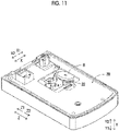
- the user attaches the button battery B by pressing and expanding (flexurally deforming) the pair of arm portions having the arc shape 21a of the snap-fit portion 21, in a state where the button battery B is tilted to the X direction along a surface of the back side of the operation panel board 50 (in a slanted state), as shown in Fig. 11 .
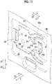
- the rear cover 20 includes a flexure regulating portion 22 that regulates the flexural deformation amount of the snap-fit portion 21 at the time of the attachment and detachment of the button battery B, as shown in Figs. 11 and 12 .
- the flexure regulating portion 22 is a wall having an arc shape formed (disposed) along the pair of arm portions having the arc shape 21a of the snap-fit portion 21.
- the snap-fit portion 21 is provided with a positioning projection portion 21c for positioning a position of the button battery B with respect to the positive terminal 52, as shown in Fig. 12 .
- the positioning projection portion 21c projects to the side where the button battery B is disposed and to the side where the positive terminal 52 is disposed.
- the positioning projection portion 21c is provided inside each of the pair of arm portions having the arc shape 21a. That is, one positioning projection portion 21c is provided for one arm portion 21a.
- the positioning projection portion 21c is configured to project in an arc shape from the inside of each of the pair of arm portions having the arc shape 21a toward the button battery B side (negative terminal 51 side).
- the positioning projection portion 21c is provided on the operation panel board 50 side (Y1 direction side) with respect to the claw portion 21b.
- the arm portion 21a, the positioning projection portion 21c, the flexure regulating portion 22, and the intrusion prevention portion 24 are continuously (integrally) formed, as shown in Fig. 12 .
- the opening portion A1 is provided on the rear cover 20 such that the snap-fit portion 21 and the stroke area S are exposed, as shown in Fig. 12 .
- the opening portion A1 is provided on the rear cover 20 such that the flexure regulating portion 22 and the negative terminal 51 are exposed.
- the opening portion A1 is formed in a stepped shape such that the operation panel board 50 is exposed along outer edges of the arm portion 21a, the positioning projection portion 21c, the flexure regulating portion 22, and the intrusion prevention portion 24.
- the negative terminal 51 is disposed on the tip end side of the pair of arm portions having the arc shape 21a (X2 direction side) from a central portion of the position where the button battery B is disposed, in the area surrounded by the pair of arm portions having the arc shape 21a.
- the rear cover 20 covers the Y2 direction side of the positive terminal 52. Therefore, the user inserts (attaches) the button battery B into the area surrounded by the pair of arm portions having the arc shape 21a, in the state where the button battery B is tilted to the X direction along the surface of the back side of the operation panel board 50 (in the slanted state) such that the outer peripheral surface P on the X1 direction side faces the Y1 direction side.
- the negative terminal 51 is disposed at a position where the positive and negative poles of the button battery B are not short-circuited even in a case where the button battery B is inserted in a tilted state (inserted slantingly) into the area surrounded by the pair of arm portions having the arc shape 21a.
- the negative terminal 51 is disposed at a position shifted toward the X2 direction side from the central portion of the position where the button battery B is disposed, up to a position where a tilt angle of the button battery B with respect to the negative terminal 51 can be increased to an angle ⁇ where both the positive and negative poles of the button battery B do not contact the negative terminal 51 at the same time (refer to Fig. 15 ).
- the operation button 2 (switch 4) for operating the power conversion device main body portion 102 is provided on the front side (Y1 direction side) of the operation panel board 50.
- the negative terminal 51 and the positive terminal 52 are provided, corresponding to the button battery B, on the back surface (surface on Y2 direction side) of the operation panel board 50. Accordingly, the button battery B can be mounted on the back surface (surface on Y2 direction side) of the operation panel board 50 provided with the negative terminal 51 and the positive terminal 52.
- the battery cover 30 configured to be attached to and detached from the rear cover 20 covers the opening portion A1 provided such that the snap-fit portion 21 is exposed. Therefore, the user can attach and detach the button battery B (replace button battery B) with respect to the snap-fit portion 21 that positions the button battery B by detaching the battery cover 30.
- the operation panel 101 and the power conversion device 100 capable of suppressing the narrowing of the space on the operation button 2 (switch 4) side of the operation panel 101 while mounting the button battery B for supplying the power to the operation panel 101 in a replaceable manner.
- the operation panel 101 main body is detachably attached to the power conversion device main body portion 102, as described above. Accordingly, it is possible to easily attach and detach the button battery B (replace button battery B) with respect to the negative terminal 51 and the positive terminal 52 provided on the back surface (surface on Y2 direction side) of the operation panel board 50.
- the card slot portion 53 for inserting the memory card C is provided on the back surface (surface on Y2 direction side) of the operation panel board 50. Therefore, it is possible to store the communication setting, the communication log, or the like with the device outside the power conversion device 100 in the memory card C by mounting the memory card C on the back surface of the operation panel board 50, as described above.
- the operation panel board 50 is provided with the stroke area S for sliding the memory card C to insert the card into the card slot portion 53 and remove the card from the card slot portion 53. Therefore, it is possible to easily insert the memory card C into the card slot portion 53 and remove the memory card C from the card slot portion 53.
- the opening portion A1 is provided, on the rear cover 20, such that the snap-fit portion 21 and the stroke area S are exposed. Therefore, it is possible to provide the battery cover 30 provided so as to cover the opening portion A1 in common with respect to the snap-fit portion 21 and the stroke area S. As a result, it is possible to suppress an increase in the number of components and a complicated device configuration.
- the stroke area S is provided between the card slot portion 53 and the snap-fit portion 21, as described above. Accordingly, it is possible to put the snap-fit portion 21 and the stroke area S close to each other, unlike the case where the stroke area S is provided on the side (X2 direction side) opposite to the side where the snap-fit portion 21 is disposed with respect to the card slot portion 53. Therefore, it is possible to reduce the opening portion A1 where the snap-fit portion 21 and the stroke area S are exposed. As a result, when the user detaches the battery cover 30 provided so as to cover the opening portion A1 and performs the work, it is possible to suppress intrusion of foreign matter into the operation panel 101.
- the snap-fit portion 21 is configured to be flexurally deformable at the time of the attachment and detachment of the button battery B
- the rear cover 20 includes the flexure regulating portion 22 that regulates the flexural deformation amount of the snap-fit portion 21 at the time of the attachment and detachment of the button battery B, as described above. Accordingly, since the flexure regulating portion 22 can regulate the flexural deformation amount of the snap-fit portion 21, it is possible to suppress damage of the snap-fit portion 21 due to excessive flexure of the snap-fit portion 21 at the time of the attachment and detachment of the button battery B (replacement of button battery B).
- the snap-fit portion 21 is provided along the outer peripheral surface P of the button battery B and is configured to be flexurally deformable at the time of the attachment and detachment of the button battery B, as described above. Accordingly, since the snap-fit portion 21 can be flexurally deformed at the time of the attachment and detachment of the button battery B, it is possible to easily attach and detach the button battery B (replace button battery B).
- the snap-fit portion 21 provided along the outer peripheral surface P of the button battery B is provided with the positioning projection portion 21c that projects on the side where the button battery B is disposed and on the side where the positive terminal 52 is disposed. Therefore, it is possible to press the button battery B attached to the snap-fit portion 21 toward the positive terminal 52 side. As a result, it is possible to reliably bring the button battery B and the positive terminal 52 into contact with each other at the time of the attachment of the button battery B.
- the snap-fit portion 21 includes the pair of arm portions having the arc shape 21a, which are elastically deformable, provided in the arc shape along the outer peripheral surface P of the button battery B, and the tip ends of the pair of arm portions having the arc shape 21a are provided on the side where the stroke area S is disposed with respect to the button battery B (X2 direction side), as described above. Accordingly, the user can easily press and expand the pair of arm portions having the arc shape 21a, which are elastically deformable, of the snap-fit portion 21 from the stroke area S side at the time of the detachment of the button battery B. As a result, it is possible to easily detach the button battery B.
- the negative terminal 51 is disposed on the tip end side of the pair of arm portions having the arc shape 21a from the central portion of the position where the button battery B is disposed, in the area surrounded by the pair of arm portions having the arc shape 21a, as described above. Accordingly, with the disposition of the negative terminal 51 on the tip end side of the pair of arm portions having the arc shape 21a from the central portion of the position where the button battery B is disposed, it is possible to dispose the negative terminal 51 at a position separated from the positive pole provided on the outer peripheral surface P of the button battery B, compared with a case where the negative terminal 51 is disposed at the central portion of the position where the button battery B is disposed.
- the positive terminal 52 is disposed on the outer peripheral surface P side of the button battery B and is configured to be flexurally deformable, as described above.
- the rear cover 20 includes the position regulating portion 23 that regulates the position of the outer peripheral surface P of the button battery B with respect to the positive terminal 52 to regulate the flexural deformation amount of the positive terminal 52. Accordingly, with the position regulating portion 23 that regulates the position of the outer peripheral surface P of the button battery B with respect to the positive terminal 52, it is possible to regulate the flexural deformation amount of the positive terminal 52 at the time of the attachment and detachment of the button battery B (replacement of the button battery B). As a result, it is possible to prevent the positive terminal 52 from being damaged due to excessive flexure of the positive terminal 52 at the time of the attachment and detachment of the button battery B (replacement of the button battery B).
- the plurality (two) of positive terminals 52 are provided along the outer peripheral surface P of the button battery B, as described above. Accordingly, since the plurality (two) of positive terminals 52 are provided along the outer peripheral surface P of the button battery B, it is possible to bring any positive terminal 52 into contact with the button battery B even in a case where the attachment position of the button battery B is displaced on the operation panel board 50, unlike a case where only one positive terminal 52 is provided. As a result, it is possible to reliably bring the button battery B and the positive terminal 52 into contact with each other, as compared with a case where only one positive terminal 52 is provided.
- the rear cover 20 is provided along the outer edge of the stroke area S so as to project toward the operation panel board 50 side (Y1 direction side), and includes the intrusion prevention portion 24 that prevents the memory card C from intruding between the rear cover 20 and the operation panel board 50, as described above. Accordingly, it is possible to prevent the memory card C from intruding between the rear cover 20 and the operation panel board 50 when the memory card C is inserted into and removed from the card slot portion 53 in the stroke area S. As a result, it is possible to improve workability when the memory card C, which stores the communication setting, the communication log, or the like with the device outside the power conversion device 100, is inserted into and removed from the card slot portion 53.
- the battery cover 30 includes the projection portion 31 that projects toward the negative terminal 51 side (Y1 direction side) provided on the operation panel board 50 in the state of being attached to the rear cover 20 to press the button battery B toward the negative terminal 51 side, as described above. Accordingly, since the button battery B is pressed toward the negative terminal 51 side (Y1 direction side) by the projection portion 31 of the battery cover 30, it is possible to reliably bring the button battery B and the negative terminal 51 into contact with each other at the time of the attachment of the button battery B.
- the power conversion device main body portion 102 is accommodated, and the rear side (Y2 direction side) of the operation panel 101 main body is configured to be attached to the control panel 110 that performs the power control, as described above.
- the sealing member 40 provided on the outside of the battery cover 30 so as to surround the battery cover 30 is provided between the rear cover 20 and the control panel 110. Accordingly, with the sealing member 40, between the rear cover 20 and the control panel 110, provided on the outside of the battery cover 30 so as to surround the battery cover 30, it is possible to prevent water from intruding between the rear cover 20 and the control panel 110 in a state where the rear side (Y2 direction side) of the operation panel 101 main body is attached to the control panel 110. As a result, it is possible to prevent water from intruding between the rear cover 20 and the battery cover 30 in the state where the rear side (Y2 direction side) of the operation panel 101 main body is attached to the control panel 110.
- the battery cover 30 is disposed near the central portion of the surface 20a of the rear cover 20 facing the control panel 110, as described above.
- the rear cover 20 has the groove portion 25 that is formed along near an outer peripheral portion of a surface 20a of the rear cover 20 facing the control panel 110 and into which the sealing member 40 is fitted. Accordingly, since the sealing member 40 is disposed along near the outer peripheral portion of the surface 20a of the rear cover 20 facing the control panel 110, it is possible to make an area where water can be prevented from intruding between the rear cover 20 and the control panel 110 relatively large on the surface 20a of the rear cover 20 facing the control panel 110.
- the battery cover 30 With the disposition of the battery cover 30 near the central portion of the surface 20a of the rear cover 20 facing the control panel 110, it is possible to easily surround the battery cover 30 with the sealing member 40, as compared with a case where the battery cover 30 is provided near the outer peripheral portion of the surface 20a of the rear cover 20 facing the control panel 110. As a result, it is possible to easily prevent water from intruding between the rear cover 20 and the battery cover 30.
- the present invention is not limited thereto.
- the power conversion device main body portion 102 may not be accommodated in the control panel 110 (refer to Fig. 1 ) and the operation panel 101 may be directly attached to the power conversion device main body portion 102, as in the power conversion device 200 of the modification example shown in Fig. 16 .
- the opening portion A1 is provided on the rear cover 20 such that the snap-fit portion 21 (battery positioning portion) and the stroke area S are exposed, but the present invention is not limited thereto.
- the rear cover may be separately provided with an opening portion for exposing the battery positioning portion and an opening portion for exposing the stroke area.
- the stroke area S is provided between the card slot portion 53 and the snap-fit portion 21 (battery positioning portion), but the present invention is not limited thereto.
- the stroke area may be provided on the side opposite to the side where the battery positioning portion is disposed (X1 direction side) with respect to the card slot portion.
- the rear cover 20 includes the flexure regulating portion 22 that regulates the flexural deformation amount of the snap-fit portion 21 (battery positioning portion) at the time of the attachment and detachment of the button battery B, but the present invention is not limited thereto.
- the flexure regulating portion that regulates the flexural deformation amount of the battery positioning portion may be provided at a position other than the rear cover, such as the operation panel board.
- the battery positioning portion may be configured not to include the snap-fit portion.
- the battery positioning portion may be configured to be provided in the arc shape along the outer peripheral surface of the button battery and configured so as not to be flexurally deformed (to have relatively small flexural deformation), and thus the flexure regulating portion that regulates the flexural deformation amount of the battery positioning portion may not be provided on the rear cover.
- the snap-fit portion 21 is provided with the positioning projection portion 21c that projects on the side where the button battery B is disposed and on the side where the positive terminal 52 (second terminal) is disposed, in order to position the position of the button battery B with respect to the positive terminal 52 (second terminal), but the present invention is not limited thereto.
- the positioning projection portion may be provided at a position other than the rear cover, such as the operation panel board or the battery cover, in order to position the position of the button battery B with respect to the second terminal.
- the tip ends of the pair of arm portions having the arc shape 21a are provided on the side where the stroke area S is disposed with respect to the button battery B (X2 direction side), but the present invention is not limited thereto.
- the tip ends of the pair of arm portions having the arc shape may be provided on the side opposite to the side where the stroke area is disposed with respect to the button battery.
- the positive terminal 52 (second terminal) is disposed on the tip end side of the pair of arm portions having the arc shape 21a from the central portion of the position where the button battery B is disposed, in the area surrounded by the pair of arm portions having the arc shape 21a, but the present invention is not limited thereto.
- the second terminal may be disposed at the central portion of the position where the button battery is disposed, in the area surrounded by the pair of arm portions having the arc shape.
- the rear cover 20 includes the position regulating portion 23 that regulates the position of the outer peripheral surface P of the button battery B with respect to the positive terminal 52 (second terminal), but the present invention is not limited thereto.
- the position regulating portion that regulates the position of the outer peripheral surface of the button battery with respect to the second terminal may be included at a position other than the rear cover, such as the operation panel board.
- the two positive terminals 52 are provided along the outer peripheral surface P of the button battery B, but the present invention is not limited thereto. In the present invention, only one positive terminal 52 (second terminal) may be provided along the outer peripheral surface P of the button battery B, or three or more positive terminals 52 may be provided.
- the rear cover 20 includes the intrusion prevention portion 24 that prevents the memory card C from intruding between the rear cover 20 and the operation panel board 50, but the present invention is not limited thereto.
- the intrusion prevention portion that prevents the memory card from intruding between the rear cover and the operation panel board may be included at a position other than the rear cover, such as the operation panel board.
- the battery cover 30 includes the projection portion 31 that projects toward the negative terminal 51 (first terminal) side (Y1 direction side) provided on the operation panel board 50 in the state of being attached to the rear cover 20 to press the button battery B toward the negative terminal 51 side, but the present invention is not limited thereto.
- the projection portion that projects toward the first terminal side provided on the operation panel board to press the button battery toward the first terminal side may be included at a position other than the battery cover, such as the rear cover.
- the rear cover 20 has the groove portion 25 that is formed along near an outer peripheral portion of a surface 20a of the rear cover 20 facing the control panel 110 and into which the sealing member 40 is fitted, but the present invention is not limited thereto.
- the rear cover may have the sealing member directly attached to the surface of the rear cover facing the control panel without having the groove portion.
- the operation button 2 and the switch 4 are shown as an example of the operation unit, but the present invention is not limited thereto.
- the operation unit may include a touch panel provided on the display.
Landscapes
- Engineering & Computer Science (AREA)
- Microelectronics & Electronic Packaging (AREA)
- Power Engineering (AREA)
- Battery Mounting, Suspending (AREA)
- Casings For Electric Apparatus (AREA)
- Inverter Devices (AREA)
Abstract
Description
- The present invention relates to an operation panel for a power conversion device and a power conversion device, and more particularly to an operation panel for a power conversion device and a power conversion device provided with an operation unit that operates a power conversion device main body portion.
- In the related art, there is known an operation panel for a power conversion device provided with an operation unit (switch) that operates a power conversion device main body portion. Such an operation panel for a power conversion device is disclosed in, for example,
Japanese Unexamined Patent Application, First Publication No. 2005-117733 JP-A-2005-117733 -
JP-A-2005-117733 - Functions required for the operation panel for a power conversion device have been increased in recent years. The functions required for the operation panel include enabling operation even when power supply from the power conversion device main body portion is shut down, in addition to enabling communication with an external device. Therefore, there is a demand for an operation panel in which a button battery is mounted as an auxiliary power source for the operation panel when the power supply is shut down and the button battery can be replaced.
- However, in the operation panel for a power conversion device in the related art as described in
JP-A-2005-117733 - The present invention has been made to solve the above-mentioned problems, and one object of the present invention is to provide a demand for an operation panel for a power conversion device and a power conversion device capable of suppressing narrowing of a space on an operation unit side while mounting a button battery for supplying power to an operation panel in a replaceable manner.
- In order to achieve the above object, an operation panel for a power conversion device according to a first aspect of the present invention includes an operation panel board provided with operation units that operate a power conversion device main body portion on a front side, a first terminal and a second terminal provided corresponding to a button battery for supplying power to the operation panel board on a back surface of the operation panel board, a rear cover including a battery positioning portion that positions the button battery with respect to the first terminal and the second terminal and an opening portion provided such that the battery positioning portion is exposed, which is disposed so as to cover the back surface of the operation panel board, and a battery cover which is configured to be attached to and detached from the rear cover and provided so as to cover the opening portion.
- In the operation panel for a power conversion device according to the first aspect, the operation unit that operates the power conversion device main body portion is provided on the front side of the operation panel board, as described above. The first terminal and the second terminal are provided on the back surface of the operation panel board corresponding to the button battery. Accordingly, since the button battery can be mounted on the back surface of the operation panel board provided with the first terminal and the second terminal, it is possible to suppress narrowing of a space on an operation unit side of the operation panel, unlike the case where the button battery is mounted on the front side of the operation panel board provided with the operation unit. The battery cover configured to be attached to and detached from the rear cover covers the opening portion provided such that the battery positioning portion is exposed. Therefore, a user can attach and detach the button battery (replace button battery) with respect to the battery positioning portion that positions the button battery by detaching the battery cover. As a result, it is possible to suppress the narrowing of the space on the operation unit side while mounting the button battery for supplying the power to the operation panel in a replaceable manner.
- In the operation panel for a power conversion device according to the first aspect, preferably, the operation panel main body is detachably attached to the power conversion device main body portion. With this configuration, even in a case where the rear side of the operation panel main body is attached to the power conversion device main body portion, it is possible to easily attach and detach the button battery (replace button battery) with respect to the first terminal and the second terminal provided on the back surface of the operation panel board by detaching the operation panel main body from the power conversion device main body portion.
- The operation panel for a power conversion device according to the first aspect, preferably, further includes a card slot portion for inserting a memory card, which is provided on the back surface of the operation panel board. The operation panel board is provided with a stroke area for sliding the memory card to insert the card into the card slot portion and remove the card from the card slot portion. The opening portion is provided in the rear cover such that the battery positioning portion and the stroke area are exposed. A function required for the operation panel for a power conversion device includes enabling mounting of the memory card for storing a communication setting, a communication log, or the like with an external device. With the above configuration, since the card slot portion for inserting the memory card is provided on the back surface of the operation panel board, it is possible to store the communication setting, the communication log, or the like with the device outside the power conversion device in the memory card by mounting the memory card on the back surface of the operation panel board. As described above, with the configuration in which the operation panel board is provided with the stroke area for sliding the memory card to insert the card into the card slot portion and remove the card from the card slot portion, it is possible to easily insert the card into the card slot portion and remove the card from the card slot portion. Further, with the configuration in which the opening portion is provided in the rear cover such that the battery positioning portion and the stroke area are exposed, it is possible to provide the battery cover provided so as to cover the opening portion in common with respect to the battery positioning portion and the stroke area. As a result, it is possible to suppress an increase in the number of components and a complicated device configuration.
- In the configuration including the card slot portion, preferably, the stroke area is provided between the card slot portion and the battery positioning portion. With this configuration, it is possible to put the battery positioning portion and the stroke area close to each other, unlike the case where the stroke area is provided on the side opposite to the side where the battery positioning portion is disposed with respect to the card slot portion. Therefore, it is possible to reduce the opening portion where the battery positioning portion and the stroke area are exposed. As a result, when the user detaches the battery cover provided so as to cover the opening portion and performs the work, it is possible to suppress intrusion of foreign matter into the operation panel.
- In the configuration including the card slot portion, preferably, the battery positioning portion is configured to be flexurally deformable at the time of the attachment and detachment of the button battery. The rear cover further includes a flexure regulating portion that regulates a flexural deformation amount of the battery positioning portion at the time of the attachment and detachment of the button battery. With this configuration, since the flexural deformation amount of the battery positioning portion can be regulated by the flexure regulating portion, it is possible to suppress damage of the battery positioning portion due to excessive flexure of the battery positioning portion at the time of the attachment and detachment of the button battery (replacement of button battery).
- In the configuration in which the stroke area is provided between the card slot portion and the battery positioning portion, preferably, the battery positioning portion includes a snap-fit portion that is provided along an outer peripheral surface of the button battery and is flexurally deformable at the time of the attachment and detachment of the button battery. The snap-fit portion is provided with a positioning projection portion that projects on a side where the button battery is disposed and on a side where the second terminal is disposed, in order to position a position of the button battery with respect to the second terminal. With this configuration, since the snap-fit portion is flexurally deformed at the time of the attachment and detachment of the button battery, it is possible to easily attach and detach the button battery (replace button battery). The snap-fit portion provided along the outer peripheral surface of the button battery is provided with the positioning projection portion that projects on the side where the button battery is disposed and on the side where the second terminal is disposed. Therefore, it is possible to press the button battery attached to the snap-fit portion toward the second terminal side. As a result, it is possible to reliably bring the button battery and the second terminal into contact with each other at the time of the attachment of the button battery.
- In the configuration in which the battery positioning portion includes the snap-fit portion, the snap-fit portion includes a pair of arm portions having an arc shape, which are elastically deformable, provided in an arc shape along the outer peripheral surface of the button battery. Tip ends of the pair of arm portions having the arc shape are provided on a side where the stroke area is disposed with respect to the button battery. With this configuration, the user can easily press and expand the pair of arm portions having the arc shape, which are elastically deformable, of the snap-fit portion from the stroke area side at the time of the detachment of the button battery. As a result, it is possible to easily detach the button battery.
- In this case, preferably, the first terminal is disposed on a tip end side of the pair of arm portions having the arc shape from a central portion of the position where the button battery is disposed, in an area surrounded by the pair of arm portions having the arc shape. The button battery is provided with a negative pole on one side surface, a positive pole provided on the other side surface, and a positive pole also provided on the outer peripheral surface of the button battery. Therefore, when the button battery is tilted and inserted into the area surrounded by the pair of arm portions having the arc shape from the tip end side of the pair of arm portions having the arc shape, the positive and negative poles of the button battery may be short-circuited due to contact of the positive pole provided on the outer peripheral surface of the button battery and the negative pole provided on one side surface of the button battery with the terminal provided on the operation panel board at the same time. On the contrary, in the present invention, the first terminal is disposed on the tip end side of the pair of arm portions having the arc shape from the central portion of the position where the button battery is disposed. Therefore, it is possible to dispose the first terminal at a position separated from the positive pole provided on the outer peripheral surface of the button battery, as compared with the case where the first terminal is disposed at the central portion of the position where the button battery is disposed, as described above. As a result, it is possible to prevent the positive and negative poles of the button battery from being short-circuited due to the contact of both the positive and negative poles of the button battery with the first terminal at the time of the attachment and detachment of the button battery (replacement of the button battery).
- In the configuration in which the battery positioning portion includes the snap-fit portion, preferably, the second terminal is disposed on an outer peripheral surface side of the button battery and is configured to be flexurally deformable. The rear cover further includes a position regulating portion that regulates a position of the outer peripheral surface of the button battery with respect to the second terminal in order to regulate a flexural deformation amount of the second terminal. With this configuration, with the position regulating portion that regulates the position of the outer peripheral surface of the button battery with respect to the second terminal, it is possible to regulate the flexural deformation amount of the second terminal at the time of the attachment and detachment of the button battery (replacement of the button battery). As a result, it is possible to prevent the second terminal from being damaged due to excessive flexure of the second terminal at the time of the attachment and detachment of the button battery (replacement of the button battery).
- In the configuration in which the battery positioning portion includes the snap-fit portion, preferably, a plurality of the second terminals are provided along the outer peripheral surface of the button battery. With this configuration, since the plurality of second terminals are provided along the outer peripheral surface of the button battery, it is possible to bring any second terminal into contact with the button battery even in a case where the attachment position of the button battery is displaced on the operation panel board, unlike a case where only one second terminal is provided. As a result, it is possible to reliably bring the button battery and the second terminal into contact with each other, as compared with the case where only one second terminal is provided.
- In the configuration including the card slot portion, preferably, the rear cover further includes an intrusion prevention portion that prevents the memory card from intruding between the rear cover and the operation panel board, which is provided along an outer edge of the stroke area so as to project toward the operation panel board side. With this configuration, it is possible to prevent the memory card from intruding between the rear cover and the operation panel board when the memory card is inserted into and removed from the card slot portion in the stroke area. As a result, it is possible to improve workability when the memory card, which stores the communication setting, the communication log, or the like with the device outside the power conversion device, is inserted into and removed from the card slot portion.
- In the operation panel for a power conversion device according to the first aspect, preferably, the battery cover includes a projection portion that projects toward a first terminal side provided on the operation panel board in a state of being attached to the rear cover to press the button battery toward the first terminal side. With this configuration, since the button battery is pressed toward the first terminal side by the projection portion of the battery cover, it is possible to reliably bring the button battery and the first terminal into contact with each other at the time of the attachment of the button battery.
- In the operation panel for a power conversion device according to the first aspect, preferably, the power conversion device main body portion is accommodated and a rear side of an operation panel main body is configured to be attached to a control panel that performs power control. The operation panel further includes a sealing member, between the rear cover and the control panel, provided on an outside of the battery cover so as to surround the battery cover. With this configuration, with the sealing member, between the rear cover and the control panel, provided on the outside of the battery cover so as to surround the battery cover, it is possible to prevent water from intruding between the rear cover and the control panel in a state where the rear side of the operation panel main body is attached to the control panel. As a result, it is possible to prevent water from intruding between the rear cover and the battery cover in the state where the rear side of the operation panel main body is attached to the control panel.
- In this case, preferably, the battery cover is disposed at a central portion of a surface of the rear cover facing the control panel. The rear cover has a groove portion that is formed along an outer peripheral portion of the surface of the rear cover facing the control panel and into which the sealing member is fitted. With this configuration, since the sealing member is disposed along the outer peripheral portion of the surface of the rear cover facing the control panel, it is possible to make an area where water can be prevented from intruding between the rear cover and the control panel relatively large on the surface of the rear cover facing the control panel. With the disposition of the battery cover near the central portion of the surface of the rear cover facing the control panel, it is possible to easily surround the battery cover with the sealing member, as compared with a case where the battery cover is provided near the outer peripheral portion of the surface of the rear cover facing the control panel. As a result, it is possible to easily prevent water from intruding between the rear cover and the battery cover.
- In order to achieve the above object, a power conversion device according to a second aspect of the present invention includes a power conversion device main body portion, and an operation panel that is detachably attached to the power conversion device main body portion and receives an operation on the power conversion device main body portion. The operation panel includes an operation panel board provided with operation units that operate the power conversion device main body portion on a front side, a first terminal and a second terminal provided corresponding to a button battery for supplying power to the operation panel board on a back surface of the operation panel board, a rear cover including a battery positioning portion that positions the button battery with respect to the first terminal and the second terminal and an opening portion provided such that the battery positioning portion is exposed, which is disposed so as to cover the back surface of the operation panel board, and a battery cover which is configured to be attached to and detached from the rear cover and provided so as to cover the opening portion.
- In the power conversion device according to the second aspect, the operation unit that operates the power conversion device main body portion is provided on the front side of the operation panel board, as described above. The first terminal and the second terminal are provided on the back surface of the operation panel board corresponding to the button battery. Accordingly, since the button battery can be mounted on the back surface of the operation panel board provided with the first terminal and the second terminal, it is possible to suppress the narrowing of the space on the operation unit side, unlike the case where the button battery is mounted on the front side of the operation panel board provided with the operation unit. The battery cover configured to be attached to and detached from the rear cover of the operation panel is configured to cover the opening portion provided such that the battery positioning portion is exposed. Accordingly, the user can attach and detach the button battery with respect to the battery positioning portion that positions the button battery by detaching the battery cover from the operation panel in a state of being detached from the power conversion device main body portion. As a result, it is possible to provide the power conversion device capable of suppressing the narrowing of the space on the operation unit side of the operation panel while mounting the button battery for supplying the power to the operation panel in a replaceable manner. With the attachment of the operation panel to the power conversion device main body portion in a detachable manner, even in the case where the rear side of the operation panel main body is attached to the power conversion device main body portion, it is possible to easily attach and detach the button battery (replace button battery) with respect to the first terminal and the second terminal provided on the back surface of the operation panel board by detaching the operation panel main body from the power conversion device main body portion.
- The foregoing and other objects, features, aspects and advantages of the present invention will become more apparent from the following detailed description of the present invention when taken in conjunction with the accompanying drawings.
-
- [
Fig. 1] Fig. 1 is a view of a state in which an operation panel according to an embodiment of the present invention is attached to a control panel. - [
Fig. 2] Fig. 2 is a perspective view of a front side of the operation panel. - [
Fig. 3] Fig. 3 is a perspective view of a rear side of the operation panel. - [
Fig. 4] Fig. 4 is a disassembled perspective view seen from the rear side of the operation panel. - [
Fig. 5A] Fig. 5A is a view of an operation panel board and is a view of a front surface of the operation panel board. - [
Fig. 5B] Fig. 5B is a view of the operation panel board and is a view of a back surface of the operation panel board. - [
Fig. 6] Fig. 6 is a rear view of the operation panel. - [
Fig. 7] Fig. 7 is a view of a sealing member in a state where the operation panel is attached to the control panel. - [
Fig. 8] Fig. 8 is a partial sectional view taken along a line 300-300 ofFig. 6 . - [
Fig. 9] Fig. 9 is the rear view of the operation panel in a state where a battery cover is detached. - [
Fig. 10] Fig. 10 is a partial cross-sectional view taken along a line 400-400 ofFig. 9 . - [
Fig. 11] Fig. 11 is a perspective view for describing attachment of a button battery to the operation panel. - [
Fig. 12] Fig. 12 is a view of a configuration of a snap-fit portion. - [
Fig. 13] Fig. 13 is the rear view of the operation panel in a state where the button battery is detached. - [
Fig. 14] Fig. 14 is a first view for describing disposition of a negative terminal. - [
Fig. 15] Fig. 15 is a second view for describing the disposition of the negative terminal. - [
Fig. 16] Fig. 16 is a view of a power conversion device according to a modification example. - Hereinafter, embodiments embodying the present invention will be described with reference to drawings.
- An overall configuration of a
power conversion device 100 and anoperation panel 101 according to one embodiment of the present invention will be described with reference toFig. 1 . Theoperation panel 101 is an example of an"operation panel for a power conversion device" in the claims. - The
power conversion device 100 includes a power conversion devicemain body portion 102 and theoperation panel 101 that receives an operation on the power conversion devicemain body portion 102. - The
operation panel 101 is configured such that a rear side (Y2 direction side) of theoperation panel 101 main body is attached to acontrol panel 110. Thecontrol panel 110 is configured to accommodate the power conversion devicemain body portion 102 and perform power control. - The
control panel 110 is configured to control the power supplied to a load (not shown) outside thecontrol panel 110. An electric device other than the power conversion devicemain body portion 102, such as a circuit breaker, an on/off switch, a switch (push button), a display, or an electric meter, may be accommodated inside thecontrol panel 110. - The
power conversion device 100 is, for example, an inverter device that converts AC power input from a commercial power source and outputs the converted power to the load. Thepower conversion device 100 is configured to communicate with an external device such as a personal computer (PC) . - The
operation panel 101 is a device that operates a power conversion operation by the power conversion device 100 (power conversion device main body portion 102). Theoperation panel 101 is configured to be attached to and detached from thecontrol panel 110 that accommodates the power conversion devicemain body portion 102. Theoperation panel 101 is attached detachably (to be attachable and detachable) to the power conversion devicemain body portion 102. - The
operation panel 101 is configured such that the power is supplied from a button battery B (refer toFig. 4 ) when the power supply is shut off, such as when the power conversion operation by the power conversion devicemain body portion 102 is stopped. Accordingly, theoperation panel 101 is configured to maintain an operable state even when the power supply from the power conversion devicemain body portion 102 is shut off. That is, theoperation panel 101 uses the button battery B as an auxiliary power source. - As shown in
Fig. 2 , theoperation panel 101 includes amain body cover 10. Adisplay 1, anoperation button 2, and aterminal cover 3 are provided on a front side (Y1 direction side) of theoperation panel 101. - The
display 1 is a display device that checks a state, setting, or the like of the power conversion device 100 (power conversion device main body portion 102). Thedisplay 1 includes a liquid crystal display or an organic EL display. - The
operation button 2 is a button for operating the power conversion device main body portion 102 (power conversion device 100). Theoperation button 2 is provided on the front side (Y1 direction side) of an operation panel board 50 (refer toFig. 5A ) described below. Theoperation button 2 is a push button disposed so as to correspond to a plurality of switches 4 (refer toFig. 5A ) provided on the front side (Y1 direction side) of theoperation panel board 50 described below. Theoperation button 2 and theswitch 4 are examples of an "operation unit" in the claims. - The
operation panel 101 is configured to receive an input operation based on the input operation by a user on a plurality ofoperation buttons 2. That is, the user can change the operation, setting, or the like of the power conversion device 100 (power conversion device main body portion 102) by operating theoperation button 2. - The
terminal cover 3 is provided so as to cover a connector 5 (refer toFig. 5A ) described below. Theterminal cover 3 is configured detachably such that theconnector 5 can be exposed when theconnector 5 is used. Theterminal cover 3 is configured to be elastically deformable. Theterminal cover 3 is made of rubber, for example. - As shown in
Fig. 3 , theoperation panel 101 includes arear cover 20 and abattery cover 30. Therear cover 20 and thebattery cover 30 are disposed on the rear side (Y2 direction side) of theoperation panel 101. - As shown in
Fig. 3 , theoperation panel 101 includes a sealingmember 40 provided on the outside of thebattery cover 30 so as to surround thebattery cover 30. The sealingmember 40 includes a waterproof packing. The sealingmember 40 may include a potting material. - A hole portion for fastening H1 is provided on the rear side (Y2 direction side) of the
operation panel 101, as shown inFig. 3 . The hole portion for fastening H1 is provided on therear cover 20 and is a hole portion used when theoperation panel 101 is fastened and fixed to thecontrol panel 110. - On the rear side (Y2 direction side) of the
operation panel 101,connectors main body portion 102 and the operation panel 101 (operation panel board 50) are provided, as shown inFig. 3 . - Each of the
connectors Fig. 4 ) toward the outside (Y2 direction side) of theoperation panel 101. - As shown in
Fig. 4 , theoperation panel 101 includes theoperation panel board 50. Theoperation panel board 50 is a printed circuit board (PCB) in which a wiring pattern is formed by a conductor and electronic components EC such as a central processing unit (CPU) and a read only memory (ROM) or a random access memory (RAM) are mounted. - The
operation panel 101 includes anegative terminal 51 and apositive terminal 52, which correspond to the button battery B for supplying the power to theoperation panel board 50, provided on the back surface (surface on Y2 direction side) of theoperation panel board 50. Thenegative terminal 51 is an example of a "first terminal" in the claims, and thepositive terminal 52 is an example of a "second terminal" in the claims. - The
negative terminal 51 is provided on the back surface (surface on Y2 direction side) of theoperation panel board 50 so as to be pressed from the Y2 direction side by a negative pole on a lower surface of the button battery B. Thenegative terminal 51 is configured to be flexurally deformable in the Y1 direction side. Thepositive terminal 52 is provided on the back surface (surface on Y2 direction side) of theoperation panel board 50 so as to be pressed from an X2 direction side by a positive pole of an outer peripheral surface P (refer toFig. 8 ) of the button battery B. - The button battery B is a battery having a button shape (coin shape). The button battery B may be a primary battery or a secondary battery. The button battery B may be a battery containing lithium or a battery containing an alkaline material.
- The
operation panel 101 is provided on the back surface (surface on Y2 direction side) of theoperation panel board 50 and includes acard slot portion 53 for inserting a memory card C, as shown inFig. 4 . The operation panel 101 (operation panel board 50) is configured such that data can be written (saved) to the inserted memory card C using thecard slot portion 53 and such that the data stored (saved) in the inserted memory card C can be read. - The memory card C is a storage device having a card shape including a flash memory and the like. For example, the memory card C is an SD memory card, a USB memory card, or a memory stick. The memory card C stores data such as a communication log or a communication setting with a device outside the power conversion device 100 (power conversion device main body portion 102).
- The
operation panel board 50 is accommodated inside themain body cover 10. A sealing member 60 (refer toFig. 4 ) is provided so as to surround theoperation panel board 50. The sealingmember 60 includes a waterproof packing. The sealingmember 60 may be a member (sealing member) containing the same material as the sealingmember 40 or may be a member containing a different material. Themain body cover 10 is provided with a hole portion for fastening H2 (refer toFig. 4 ) that communicates with the hole portion for fastening H1 of therear cover 20. - The
rear cover 20 has agroove portion 25 that is formed along near an outer peripheral portion of asurface 20a of therear cover 20 facing thecontrol panel 110 and into which the sealingmember 40 is fitted (refer toFig. 4 ). The sealingmember 40 adheres to thegroove portion 25 with a double-sided tape or the like. - The
rear cover 20 is provided with a snap-fit portion 21 (refer toFig. 4 ) for positioning the button battery B with respect to thenegative terminal 51 and thepositive terminal 52 and an opening portion A1 provided so as to expose the snap-fit portion 21 (refer toFig. 4 ). The snap-fit portion 21 is an example of a "battery positioning portion" in the claims. In the present embodiment, the snap-fit portion 21 can position the button battery B with respect to thenegative terminal 51 and thepositive terminal 52. Therefore, when the button battery B is attached, the button battery B can be reliably contacted with thenegative terminal 51 and thepositive terminal 52. - The
rear cover 20 is provided with an opening portion A2 for exposing theconnector 6 and an opening portion A3 for exposing theconnector 7. - The
rear cover 20 is disposed so as to cover the back surface of theoperation panel board 50. Therear cover 20 has a snap-fit portion 20b (refer toFig. 4 ) that projects toward the main body cover 10 (operation panel board 50) side (Y1 direction side). Therear cover 20 is configured to be fitted and fixed to themain body cover 10 by the snap-fit portion 20b. With the sealingmember 60 provided so as to surround theoperation panel board 50, it is possible to prevent water from intruding between therear cover 20 and the main body cover 10 (gap). - The
battery cover 30 is configured to be attached to and detached from therear cover 20. Thebattery cover 30 is provided with ahole portion 30a (refer toFig. 4 ). - The
main body cover 10, therear cover 20, and thebattery cover 30 are made of members containing resin. Themain body cover 10, therear cover 20, and thebattery cover 30 are formed of, for example, ABS resin. - As shown in
Fig. 5A , thedisplay 1, theswitch 4, and theconnector 5 are provided (implemented) on the front side (Y1 direction side) of theoperation panel board 50. The plurality ofswitches 4 are provided corresponding to the plurality ofoperation buttons 2. Theconnector 5 is provided for communicably connecting to the device outside the power conversion device 100 (control panel 110) such as a personal computer (PC). For example, theconnector 5 is a USB terminal that is communicably connected to the device outside the power conversion device 100 (control panel 110) such as the PC. Thedisplay 1, theswitch 4, and theconnector 5 are electrically connected to the wiring pattern formed on theoperation panel board 50. - As shown in
Fig. 5B , theconnector 6, theconnector 7, thenegative terminal 51, thepositive terminal 52, and thecard slot portion 53 are provided (implemented) on a back side (Y2 direction side) of theoperation panel board 50. Thepositive terminal 52, thenegative terminal 51, and thecard slot portion 53 are disposed in this order from an X1 direction side, viewed from the back side (Y2 direction side) of theoperation panel board 50. Thenegative terminal 51, thepositive terminal 52, and thecard slot portion 53 are electrically connected to the wiring pattern formed on theoperation panel board 50. - The
negative terminal 51, thepositive terminal 52, and thecard slot portion 53 are provided near a central portion on the back side (Y2 direction side) of theoperation panel board 50 in a Z direction. Thenegative terminal 51, thepositive terminal 52, and thecard slot portion 53 are disposed at a position overlapping thedisplay 1 provided on the front side (Y1 direction side) of theoperation panel board 50, viewed from a Y direction (Y1 direction side or Y2 direction side) (refer toFigs. 5A and 5B ). - As shown in
Fig. 6 , thebattery cover 30 is disposed near a central portion of thesurface 20a of therear cover 20 facing thecontrol panel 110. - The
battery cover 30 is provided so as to cover the opening portion A1 (refer toFig. 4 ). In a state where thebattery cover 30 is attached, aclaw portion 21b of the snap-fit portion 21 described below is configured to be exposed from thehole portion 30a of thebattery cover 30, as shown inFig. 6 . - The sealing
member 40 is disposed so as to surround the connector 6 (opening portion A2), the connector 7 (opening portion A3), and the hole portion for fastening H1, as shown inFig. 6 . That is, theoperation panel 101 is attached to thecontrol panel 110 on thesurface 20a of therear cover 20 facing thecontrol panel 110, using the hole portion for fastening H1 provided inside the sealingmember 40. - As shown in
Fig. 7 , the sealingmember 40 is disposed between therear cover 20 and thecontrol panel 110 when the rear side (Y2 direction side) of theoperation panel 101 is attached to thecontrol panel 110. The sealingmember 40 is configured such that the main body of the operation panel 101 (rear cover 20) is attached to thecontrol panel 110 and is pressed against thecontrol panel 110 to be elastically deformed. - As shown in
Fig. 8 , thepositive terminal 52 is disposed on the outer peripheral surface P side of the button battery B and is configured to be flexurally deformable. Therear cover 20 includes aposition regulating portion 23 that regulates a position of the outer peripheral surface P of the button battery B with respect to thepositive terminal 52 in order to regulate a flexural deformation amount of thepositive terminal 52, as shown inFig. 8 . Theposition regulating portion 23 is a step provided on therear cover 20, and the button battery B is caught by the position regulating portion 23 (step) to regulate movement of the button battery B in the X1 direction side. - The
battery cover 30 includes aprojection portion 31 that projects toward thenegative terminal 51 side (Y1 direction side) provided on theoperation panel board 50 in a state of being attached to therear cover 20 to press the button battery B toward thenegative terminal 51 side (refer toFig. 8 ). A tip end of the projection portion 31 (end portion on Y1 direction side) is formed flat and presses the button battery B from the Y2 direction side in the state where thebattery cover 30 is attached. - As shown in
Fig. 9 , theoperation panel board 50 is provided with a stroke area S for sliding the memory card C to insert the card into thecard slot portion 53 and remove the card from thecard slot portion 53. - As shown in
Fig. 9 , thepositive terminal 52 is disposed on the outside (X1 direction side) of the opening portion A1 provided on thesurface 20a of therear cover 20, viewed from the Y2 direction side. As shown inFig. 9 , in a state where the button battery B is attached, a part of thepositive terminal 52 side (X1 direction side) of the button battery B is disposed on the outside (X1 direction side) of the opening portion A1 provided on thesurface 20a of therear cover 20, viewed from the Y2 direction side. That is, thepositive terminal 52 and the part of thepositive terminal 52 side of the button battery B are covered with therear cover 20 on the Y2 direction side. - As shown in
Fig. 9 , the stroke area S is provided between thecard slot portion 53 and the snap-fit portion 21. The stroke area S is an area for sliding and moving the memory card C and is an area where a component constituting an electronic circuit, such as the electronic component EC, is not attached (not implemented) on the back surface (surface on Y2 direction side) of theoperation panel board 50. - Accordingly, the user can insert the memory card C into the
card slot portion 53 by sliding and moving the memory card C from the stroke area S to thecard slot portion 53 side (X2 direction side). The user can remove the memory card C from thecard slot portion 53 by sliding and moving the memory card C from thecard slot portion 53 to the stroke area S side (X1 direction side). - In the present embodiment, a plurality (two) of
positive terminals 52 are provided along the outer peripheral surface P of the button battery B, as shown inFig. 9 . The plurality ofpositive terminals 52 are electrically connected by a conductor pattern formed on theoperation panel board 50. - As shown in
Fig. 9 , the snap-fit portion 21 is provided along the outer peripheral surface P of the button battery B and is configured to be flexurally deformable at the time of the attachment and detachment of the button battery B. - As shown in
Fig. 9 , the snap-fit portion 21 includes a pair of arm portions having anarc shape 21a, which are elastically deformable, provided in an arc shape along the outer peripheral surface P of the button battery B. - As shown in
Fig. 9 , in the snap-fit portion 21, tip ends of the pair of arm portions having thearc shape 21a are provided on the side where the stroke area S is disposed with respect to the button battery B (X2 direction side). - As shown in
Fig. 9 , the snap-fit portion 21 includesclaw portions 21b provided near tip end portions of the pair of arm portions having thearc shape 21a. Theclaw portion 21b is configured to cover (press) a part of the button battery B from the Y2 direction side in a state where the button battery B is attached to an area surrounded by the pair of arm portions having thearc shape 21a. - As shown in
Fig. 10 , therear cover 20 includes anintrusion prevention portion 24 that prevents the memory card C from intruding between therear cover 20 and theoperation panel board 50 by projecting toward theoperation panel board 50 side (Y1 direction side). Theintrusion prevention portion 24 is provided along an outer edge of the stroke area S, as shown inFig. 9 . - A distance D1, in the Y direction, between the
intrusion prevention portion 24 and the operation panel board 50 (refer toFig. 10 ) is smaller than a width W, in the Y direction, of aninsertion port 53a of thecard slot portion 53 into which the memory card C is inserted (refer toFig. 10 ). The distance D1, in the Y direction, between theintrusion prevention portion 24 and the operation panel board 50 (refer toFig. 10 ) is a size such that the memory card C does not enter between therear cover 20 and theoperation panel board 50. - At the time of the attachment of the button battery B, the user attaches the button battery B by pressing and expanding (flexurally deforming) the pair of arm portions having the
arc shape 21a of the snap-fit portion 21, in a state where the button battery B is tilted to the X direction along a surface of the back side of the operation panel board 50 (in a slanted state), as shown inFig. 11 . - The
rear cover 20 includes aflexure regulating portion 22 that regulates the flexural deformation amount of the snap-fit portion 21 at the time of the attachment and detachment of the button battery B, as shown inFigs. 11 and12 . Theflexure regulating portion 22 is a wall having an arc shape formed (disposed) along the pair of arm portions having thearc shape 21a of the snap-fit portion 21. - The snap-
fit portion 21 is provided with apositioning projection portion 21c for positioning a position of the button battery B with respect to thepositive terminal 52, as shown inFig. 12 . Thepositioning projection portion 21c projects to the side where the button battery B is disposed and to the side where thepositive terminal 52 is disposed. - Specifically, the
positioning projection portion 21c is provided inside each of the pair of arm portions having thearc shape 21a. That is, onepositioning projection portion 21c is provided for onearm portion 21a. Thepositioning projection portion 21c is configured to project in an arc shape from the inside of each of the pair of arm portions having thearc shape 21a toward the button battery B side (negative terminal 51 side). Thepositioning projection portion 21c is provided on theoperation panel board 50 side (Y1 direction side) with respect to theclaw portion 21b. Thearm portion 21a, thepositioning projection portion 21c, theflexure regulating portion 22, and theintrusion prevention portion 24 are continuously (integrally) formed, as shown inFig. 12 . - The opening portion A1 is provided on the
rear cover 20 such that the snap-fit portion 21 and the stroke area S are exposed, as shown inFig. 12 . The opening portion A1 is provided on therear cover 20 such that theflexure regulating portion 22 and thenegative terminal 51 are exposed. The opening portion A1 is formed in a stepped shape such that theoperation panel board 50 is exposed along outer edges of thearm portion 21a, thepositioning projection portion 21c, theflexure regulating portion 22, and theintrusion prevention portion 24. - As shown in
Fig. 13 , thenegative terminal 51 is disposed on the tip end side of the pair of arm portions having thearc shape 21a (X2 direction side) from a central portion of the position where the button battery B is disposed, in the area surrounded by the pair of arm portions having thearc shape 21a. - As shown in
Fig. 14 , therear cover 20 covers the Y2 direction side of thepositive terminal 52. Therefore, the user inserts (attaches) the button battery B into the area surrounded by the pair of arm portions having thearc shape 21a, in the state where the button battery B is tilted to the X direction along the surface of the back side of the operation panel board 50 (in the slanted state) such that the outer peripheral surface P on the X1 direction side faces the Y1 direction side. - Therefore, the
negative terminal 51 is disposed at a position where the positive and negative poles of the button battery B are not short-circuited even in a case where the button battery B is inserted in a tilted state (inserted slantingly) into the area surrounded by the pair of arm portions having thearc shape 21a. - Specifically, with the interference of the pair of arm portions having the
arc shape 21a with the button battery B, thenegative terminal 51 is disposed at a position shifted toward the X2 direction side from the central portion of the position where the button battery B is disposed, up to a position where a tilt angle of the button battery B with respect to thenegative terminal 51 can be increased to an angle θ where both the positive and negative poles of the button battery B do not contact thenegative terminal 51 at the same time (refer toFig. 15 ). - In the present embodiment, the following effects can be obtained.
- In the present embodiment, the operation button 2 (switch 4) for operating the power conversion device
main body portion 102 is provided on the front side (Y1 direction side) of theoperation panel board 50. Thenegative terminal 51 and thepositive terminal 52 are provided, corresponding to the button battery B, on the back surface (surface on Y2 direction side) of theoperation panel board 50. Accordingly, the button battery B can be mounted on the back surface (surface on Y2 direction side) of theoperation panel board 50 provided with thenegative terminal 51 and thepositive terminal 52. Therefore, it is possible to suppress narrowing of a space on the operation button 2 (switch 4) side of theoperation panel 101, unlike the case where the button battery B is mounted on the front side (Y1 direction side) of theoperation panel board 50 provided with the operation button 2 (switch 4). Thebattery cover 30 configured to be attached to and detached from therear cover 20 covers the opening portion A1 provided such that the snap-fit portion 21 is exposed. Therefore, the user can attach and detach the button battery B (replace button battery B) with respect to the snap-fit portion 21 that positions the button battery B by detaching thebattery cover 30. As a result, it is possible to provide theoperation panel 101 and thepower conversion device 100 capable of suppressing the narrowing of the space on the operation button 2 (switch 4) side of theoperation panel 101 while mounting the button battery B for supplying the power to theoperation panel 101 in a replaceable manner. - In the present embodiment, the
operation panel 101 main body is detachably attached to the power conversion devicemain body portion 102, as described above. Accordingly, it is possible to easily attach and detach the button battery B (replace button battery B) with respect to thenegative terminal 51 and thepositive terminal 52 provided on the back surface (surface on Y2 direction side) of theoperation panel board 50. - In the present embodiment, the
card slot portion 53 for inserting the memory card C is provided on the back surface (surface on Y2 direction side) of theoperation panel board 50. Therefore, it is possible to store the communication setting, the communication log, or the like with the device outside thepower conversion device 100 in the memory card C by mounting the memory card C on the back surface of theoperation panel board 50, as described above. Theoperation panel board 50 is provided with the stroke area S for sliding the memory card C to insert the card into thecard slot portion 53 and remove the card from thecard slot portion 53. Therefore, it is possible to easily insert the memory card C into thecard slot portion 53 and remove the memory card C from thecard slot portion 53. Further, the opening portion A1 is provided, on therear cover 20, such that the snap-fit portion 21 and the stroke area S are exposed. Therefore, it is possible to provide thebattery cover 30 provided so as to cover the opening portion A1 in common with respect to the snap-fit portion 21 and the stroke area S. As a result, it is possible to suppress an increase in the number of components and a complicated device configuration. - In the present embodiment, the stroke area S is provided between the
card slot portion 53 and the snap-fit portion 21, as described above. Accordingly, it is possible to put the snap-fit portion 21 and the stroke area S close to each other, unlike the case where the stroke area S is provided on the side (X2 direction side) opposite to the side where the snap-fit portion 21 is disposed with respect to thecard slot portion 53. Therefore, it is possible to reduce the opening portion A1 where the snap-fit portion 21 and the stroke area S are exposed. As a result, when the user detaches thebattery cover 30 provided so as to cover the opening portion A1 and performs the work, it is possible to suppress intrusion of foreign matter into theoperation panel 101. - In the present embodiment, the snap-
fit portion 21 is configured to be flexurally deformable at the time of the attachment and detachment of the button battery B, and therear cover 20 includes theflexure regulating portion 22 that regulates the flexural deformation amount of the snap-fit portion 21 at the time of the attachment and detachment of the button battery B, as described above. Accordingly, since theflexure regulating portion 22 can regulate the flexural deformation amount of the snap-fit portion 21, it is possible to suppress damage of the snap-fit portion 21 due to excessive flexure of the snap-fit portion 21 at the time of the attachment and detachment of the button battery B (replacement of button battery B). - In the present embodiment, the snap-
fit portion 21 is provided along the outer peripheral surface P of the button battery B and is configured to be flexurally deformable at the time of the attachment and detachment of the button battery B, as described above. Accordingly, since the snap-fit portion 21 can be flexurally deformed at the time of the attachment and detachment of the button battery B, it is possible to easily attach and detach the button battery B (replace button battery B). The snap-fit portion 21 provided along the outer peripheral surface P of the button battery B is provided with thepositioning projection portion 21c that projects on the side where the button battery B is disposed and on the side where thepositive terminal 52 is disposed. Therefore, it is possible to press the button battery B attached to the snap-fit portion 21 toward thepositive terminal 52 side. As a result, it is possible to reliably bring the button battery B and thepositive terminal 52 into contact with each other at the time of the attachment of the button battery B. - In the present embodiment, the snap-
fit portion 21 includes the pair of arm portions having thearc shape 21a, which are elastically deformable, provided in the arc shape along the outer peripheral surface P of the button battery B, and the tip ends of the pair of arm portions having thearc shape 21a are provided on the side where the stroke area S is disposed with respect to the button battery B (X2 direction side), as described above. Accordingly, the user can easily press and expand the pair of arm portions having thearc shape 21a, which are elastically deformable, of the snap-fit portion 21 from the stroke area S side at the time of the detachment of the button battery B. As a result, it is possible to easily detach the button battery B. - In the present embodiment, the
negative terminal 51 is disposed on the tip end side of the pair of arm portions having thearc shape 21a from the central portion of the position where the button battery B is disposed, in the area surrounded by the pair of arm portions having thearc shape 21a, as described above. Accordingly, with the disposition of thenegative terminal 51 on the tip end side of the pair of arm portions having thearc shape 21a from the central portion of the position where the button battery B is disposed, it is possible to dispose thenegative terminal 51 at a position separated from the positive pole provided on the outer peripheral surface P of the button battery B, compared with a case where thenegative terminal 51 is disposed at the central portion of the position where the button battery B is disposed. As a result, it is possible to prevent the positive and negative poles of the button battery B from being short-circuited due to the contact of both the positive and negative poles of the button battery B with thenegative terminal 51 at the time of the attachment and detachment of the button battery B (replacement of the button battery B) . - In the present embodiment, the
positive terminal 52 is disposed on the outer peripheral surface P side of the button battery B and is configured to be flexurally deformable, as described above. Therear cover 20 includes theposition regulating portion 23 that regulates the position of the outer peripheral surface P of the button battery B with respect to thepositive terminal 52 to regulate the flexural deformation amount of thepositive terminal 52. Accordingly, with theposition regulating portion 23 that regulates the position of the outer peripheral surface P of the button battery B with respect to thepositive terminal 52, it is possible to regulate the flexural deformation amount of thepositive terminal 52 at the time of the attachment and detachment of the button battery B (replacement of the button battery B). As a result, it is possible to prevent the positive terminal 52 from being damaged due to excessive flexure of thepositive terminal 52 at the time of the attachment and detachment of the button battery B (replacement of the button battery B). - In the present embodiment, the plurality (two) of
positive terminals 52 are provided along the outer peripheral surface P of the button battery B, as described above. Accordingly, since the plurality (two) ofpositive terminals 52 are provided along the outer peripheral surface P of the button battery B, it is possible to bring anypositive terminal 52 into contact with the button battery B even in a case where the attachment position of the button battery B is displaced on theoperation panel board 50, unlike a case where only onepositive terminal 52 is provided. As a result, it is possible to reliably bring the button battery B and thepositive terminal 52 into contact with each other, as compared with a case where only onepositive terminal 52 is provided. - In the present embodiment, the
rear cover 20 is provided along the outer edge of the stroke area S so as to project toward theoperation panel board 50 side (Y1 direction side), and includes theintrusion prevention portion 24 that prevents the memory card C from intruding between therear cover 20 and theoperation panel board 50, as described above. Accordingly, it is possible to prevent the memory card C from intruding between therear cover 20 and theoperation panel board 50 when the memory card C is inserted into and removed from thecard slot portion 53 in the stroke area S. As a result, it is possible to improve workability when the memory card C, which stores the communication setting, the communication log, or the like with the device outside thepower conversion device 100, is inserted into and removed from thecard slot portion 53. - In the present embodiment, the
battery cover 30 includes theprojection portion 31 that projects toward thenegative terminal 51 side (Y1 direction side) provided on theoperation panel board 50 in the state of being attached to therear cover 20 to press the button battery B toward thenegative terminal 51 side, as described above. Accordingly, since the button battery B is pressed toward thenegative terminal 51 side (Y1 direction side) by theprojection portion 31 of thebattery cover 30, it is possible to reliably bring the button battery B and thenegative terminal 51 into contact with each other at the time of the attachment of the button battery B. - In the present embodiment, the power conversion device
main body portion 102 is accommodated, and the rear side (Y2 direction side) of theoperation panel 101 main body is configured to be attached to thecontrol panel 110 that performs the power control, as described above. The sealingmember 40 provided on the outside of thebattery cover 30 so as to surround thebattery cover 30 is provided between therear cover 20 and thecontrol panel 110. Accordingly, with the sealingmember 40, between therear cover 20 and thecontrol panel 110, provided on the outside of thebattery cover 30 so as to surround thebattery cover 30, it is possible to prevent water from intruding between therear cover 20 and thecontrol panel 110 in a state where the rear side (Y2 direction side) of theoperation panel 101 main body is attached to thecontrol panel 110. As a result, it is possible to prevent water from intruding between therear cover 20 and thebattery cover 30 in the state where the rear side (Y2 direction side) of theoperation panel 101 main body is attached to thecontrol panel 110. - In the present embodiment, the
battery cover 30 is disposed near the central portion of thesurface 20a of therear cover 20 facing thecontrol panel 110, as described above. Therear cover 20 has thegroove portion 25 that is formed along near an outer peripheral portion of asurface 20a of therear cover 20 facing thecontrol panel 110 and into which the sealingmember 40 is fitted. Accordingly, since the sealingmember 40 is disposed along near the outer peripheral portion of thesurface 20a of therear cover 20 facing thecontrol panel 110, it is possible to make an area where water can be prevented from intruding between therear cover 20 and thecontrol panel 110 relatively large on thesurface 20a of therear cover 20 facing thecontrol panel 110. With the disposition of thebattery cover 30 near the central portion of thesurface 20a of therear cover 20 facing thecontrol panel 110, it is possible to easily surround thebattery cover 30 with the sealingmember 40, as compared with a case where thebattery cover 30 is provided near the outer peripheral portion of thesurface 20a of therear cover 20 facing thecontrol panel 110. As a result, it is possible to easily prevent water from intruding between therear cover 20 and thebattery cover 30. - The embodiments disclosed this time is required to be considered as examples in all respects and not restrictive. The scope of the present invention is indicated not by the description of the above embodiment but by the scope of claims, and further includes all changes (modification examples) within the meaning and scope equivalent to the scope of claims.
- For example, in the above embodiment, an example of the operation panel 101 (operation panel for power conversion device) attached to the
control panel 110 has been shown, but the present invention is not limited thereto. For example, in the operation panel for a power conversion device, the power conversion devicemain body portion 102 may not be accommodated in the control panel 110 (refer toFig. 1 ) and theoperation panel 101 may be directly attached to the power conversion devicemain body portion 102, as in thepower conversion device 200 of the modification example shown inFig. 16 . - In the above embodiment, the opening portion A1 is provided on the
rear cover 20 such that the snap-fit portion 21 (battery positioning portion) and the stroke area S are exposed, but the present invention is not limited thereto. In the present invention, the rear cover may be separately provided with an opening portion for exposing the battery positioning portion and an opening portion for exposing the stroke area. - In the above embodiment, the stroke area S is provided between the
card slot portion 53 and the snap-fit portion 21 (battery positioning portion), but the present invention is not limited thereto. In the present invention, the stroke area may be provided on the side opposite to the side where the battery positioning portion is disposed (X1 direction side) with respect to the card slot portion. - In the above embodiment, the
rear cover 20 includes theflexure regulating portion 22 that regulates the flexural deformation amount of the snap-fit portion 21 (battery positioning portion) at the time of the attachment and detachment of the button battery B, but the present invention is not limited thereto. In the present invention, the flexure regulating portion that regulates the flexural deformation amount of the battery positioning portion may be provided at a position other than the rear cover, such as the operation panel board. In the present invention, the battery positioning portion may be configured not to include the snap-fit portion. In this case, the battery positioning portion may be configured to be provided in the arc shape along the outer peripheral surface of the button battery and configured so as not to be flexurally deformed (to have relatively small flexural deformation), and thus the flexure regulating portion that regulates the flexural deformation amount of the battery positioning portion may not be provided on the rear cover. - In the above embodiment, the snap-
fit portion 21 is provided with thepositioning projection portion 21c that projects on the side where the button battery B is disposed and on the side where the positive terminal 52 (second terminal) is disposed, in order to position the position of the button battery B with respect to the positive terminal 52 (second terminal), but the present invention is not limited thereto. In the present invention, the positioning projection portion may be provided at a position other than the rear cover, such as the operation panel board or the battery cover, in order to position the position of the button battery B with respect to the second terminal. - In the above embodiment, the tip ends of the pair of arm portions having the
arc shape 21a are provided on the side where the stroke area S is disposed with respect to the button battery B (X2 direction side), but the present invention is not limited thereto. In the present invention, the tip ends of the pair of arm portions having the arc shape may be provided on the side opposite to the side where the stroke area is disposed with respect to the button battery. - In the above embodiment, the positive terminal 52 (second terminal) is disposed on the tip end side of the pair of arm portions having the
arc shape 21a from the central portion of the position where the button battery B is disposed, in the area surrounded by the pair of arm portions having thearc shape 21a, but the present invention is not limited thereto. In the present invention, the second terminal may be disposed at the central portion of the position where the button battery is disposed, in the area surrounded by the pair of arm portions having the arc shape. - In the above embodiment, the
rear cover 20 includes theposition regulating portion 23 that regulates the position of the outer peripheral surface P of the button battery B with respect to the positive terminal 52 (second terminal), but the present invention is not limited thereto. In the present invention, the position regulating portion that regulates the position of the outer peripheral surface of the button battery with respect to the second terminal may be included at a position other than the rear cover, such as the operation panel board. - In the above embodiment, the two positive terminals 52 (second terminals) are provided along the outer peripheral surface P of the button battery B, but the present invention is not limited thereto. In the present invention, only one positive terminal 52 (second terminal) may be provided along the outer peripheral surface P of the button battery B, or three or more
positive terminals 52 may be provided. - In the above embodiment, the
rear cover 20 includes theintrusion prevention portion 24 that prevents the memory card C from intruding between therear cover 20 and theoperation panel board 50, but the present invention is not limited thereto. In the present invention, the intrusion prevention portion that prevents the memory card from intruding between the rear cover and the operation panel board may be included at a position other than the rear cover, such as the operation panel board. - In the above embodiment, the
battery cover 30 includes theprojection portion 31 that projects toward the negative terminal 51 (first terminal) side (Y1 direction side) provided on theoperation panel board 50 in the state of being attached to therear cover 20 to press the button battery B toward thenegative terminal 51 side, but the present invention is not limited thereto. In the present invention, the projection portion that projects toward the first terminal side provided on the operation panel board to press the button battery toward the first terminal side may be included at a position other than the battery cover, such as the rear cover. - In the above embodiment, the
rear cover 20 has thegroove portion 25 that is formed along near an outer peripheral portion of asurface 20a of therear cover 20 facing thecontrol panel 110 and into which the sealingmember 40 is fitted, but the present invention is not limited thereto. In the present invention, the rear cover may have the sealing member directly attached to the surface of the rear cover facing the control panel without having the groove portion. - In the above embodiment, the
operation button 2 and theswitch 4 are shown as an example of the operation unit, but the present invention is not limited thereto. In the present invention, the operation unit may include a touch panel provided on the display.
Claims (15)
- An operation panel for a power conversion device (101) comprising:an operation panel board (50) provided with operation units (2, 4) that operate a power conversion device main body portion (102) on a front side;a first terminal (51) and a second terminal (52) provided corresponding to a button battery (B) for supplying power to the operation panel board on a back surface of the operation panel board;a rear cover (20) including a battery positioning portion (21) that positions the button battery with respect to the first terminal and the second terminal and an opening portion (A1) provided such that the battery positioning portion is exposed, which is disposed so as to cover the back surface of the operation panel board; anda battery cover (30) which is configured to be attached to and detached from the rear cover and provided so as to cover the opening portion.
- The operation panel for a power conversion device according to Claim 1, wherein
the operation panel main body is detachably attached to the power conversion device main body portion. - The operation panel for a power conversion device according to Claim 1 or 2, further comprising:a card slot portion (53) for inserting a memory card (C), which is provided on the back surface of the operation panel board, whereinthe operation panel board is provided with a stroke area (S) for sliding the memory card to insert the card into the card slot portion and remove the card from the card slot portion, andthe opening portion is provided in the rear cover such that the battery positioning portion and the stroke area are exposed.
- The operation panel for a power conversion device according to Claim 3, wherein
the stroke area is provided between the card slot portion and the battery positioning portion. - The operation panel for a power conversion device according to Claim 3 or 4, whereinthe battery positioning portion is configured to be flexurally deformable at the time of the attachment and detachment of the button battery, andthe rear cover further includes a flexure regulating portion (22) that regulates a flexural deformation amount of the battery positioning portion at the time of the attachment and detachment of the button battery.
- The operation panel for a power conversion device according to Claim 4 or 5, whereinthe battery positioning portion includes a snap-fit portion (21) that is provided along an outer peripheral surface (P) of the button battery and is flexurally deformable at the time of the attachment and detachment of the button battery, andthe snap-fit portion is provided with a positioning projection portion (21c) that projects on a side where the button battery is disposed and on a side where the second terminal is disposed, in order to position a position of the button battery with respect to the second terminal.
- The operation panel for a power conversion device according to Claim 6, whereinthe snap-fit portion includes a pair of arm portions having an arc shape (21a), which are elastically deformable, provided in an arc shape along the outer peripheral surface of the button battery, andtip ends of the pair of arm portions having the arc shape are provided on a side where the stroke area is disposed with respect to the button battery.
- The operation panel for a power conversion device according to Claim 7, wherein
the first terminal is disposed on a tip end side of the pair of arm portions having the arc shape from a central portion of the position where the button battery is disposed, in an area surrounded by the pair of arm portions having the arc shape. - The operation panel for a power conversion device according to any one of Claims 6 to 8, whereinthe second terminal is disposed on an outer peripheral surface side of the button battery and is configured to be flexurally deformable, andthe rear cover further includes a position regulating portion (23) that regulates a position of the outer peripheral surface of the button battery with respect to the second terminal in order to regulate a flexural deformation amount of the second terminal.
- The operation panel for a power conversion device according to any one of Claims 6 to 9, wherein
a plurality of the second terminals are provided along the outer peripheral surface of the button battery. - The operation panel for a power conversion device according to any one of Claims 3 to 10, wherein
the rear cover further includes an intrusion prevention portion (24) that prevents the memory card from intruding between the rear cover and the operation panel board, which is provided along an outer edge of the stroke area so as to project toward the operation panel board side. - The operation panel for a power conversion device according to any one of Claims 1 to 11, wherein
the battery cover includes a projection portion (31) that projects toward a first terminal side provided on the operation panel board in a state of being attached to the rear cover to press the button battery toward the first terminal side. - The operation panel for a power conversion device according to any one of Claims 1 to 12, whereinthe power conversion device main body portion is accommodated and a rear side of an operation panel main body is configured to be attached to a control panel that performs power control, andthe operation panel further comprises a sealing member (40), between the rear cover and the control panel, provided on an outside of the battery cover so as to surround the battery cover.
- The operation panel for a power conversion device according to Claim 13, whereinthe battery cover is disposed at a central portion of a surface of the rear cover facing the control panel, andthe rear cover has a groove portion (25) which is formed along an outer peripheral portion of the surface of the rear cover facing the control panel and into which the sealing member is fitted.
- A power conversion device (100) comprising:a power conversion device main body portion (102); andan operation panel (101) according to one of the preceeding claims that is detachably attached to the power conversion device main body portion.
Applications Claiming Priority (1)
| Application Number | Priority Date | Filing Date | Title |
|---|---|---|---|
| JP2020195170A JP7596743B2 (en) | 2020-11-25 | 2020-11-25 | Operation panel for power conversion device and power conversion device |
Publications (2)
| Publication Number | Publication Date |
|---|---|
| EP4007465A1 true EP4007465A1 (en) | 2022-06-01 |
| EP4007465B1 EP4007465B1 (en) | 2023-10-18 |
Family
ID=78134773
Family Applications (1)
| Application Number | Title | Priority Date | Filing Date |
|---|---|---|---|
| EP21199579.0A Active EP4007465B1 (en) | 2020-11-25 | 2021-09-28 | Operation panel for power conversion device and power conversion device |
Country Status (3)
| Country | Link |
|---|---|
| EP (1) | EP4007465B1 (en) |
| JP (1) | JP7596743B2 (en) |
| CN (1) | CN114552942B (en) |
Citations (3)
| Publication number | Priority date | Publication date | Assignee | Title |
|---|---|---|---|---|
| JPH11233090A (en) * | 1998-02-16 | 1999-08-27 | Sony Corp | Battery lid lock mechanism |
| JP2005117733A (en) | 2003-10-06 | 2005-04-28 | Hitachi Industrial Equipment Systems Co Ltd | Power converter |
| JP2014170151A (en) * | 2013-03-05 | 2014-09-18 | Canon Inc | Electronic device |
Family Cites Families (12)
| Publication number | Priority date | Publication date | Assignee | Title |
|---|---|---|---|---|
| US5805423A (en) * | 1996-05-17 | 1998-09-08 | United Technologies Automotive | Battery contact and retention apparatus for printed circuit boards |
| JP3295637B2 (en) * | 1997-12-24 | 2002-06-24 | 東海興業株式会社 | Button battery holding structure |
| JP2007266693A (en) * | 2006-03-27 | 2007-10-11 | Sharp Corp | SIM card compatible mobile terminal device |
| JP2009259666A (en) * | 2008-04-18 | 2009-11-05 | Ishida Co Ltd | Removal structure of button battery, electronic device, and jig for removal of button battery |
| JP2012146595A (en) * | 2011-01-14 | 2012-08-02 | Mitsubishi Electric Corp | Electric device |
| JP2014107058A (en) * | 2012-11-26 | 2014-06-09 | Tokai Rika Co Ltd | Portable terminal |
| JP6657981B2 (en) * | 2016-01-18 | 2020-03-04 | 日本精機株式会社 | Battery storage structure for electronic equipment |
| JP6786983B2 (en) * | 2016-06-15 | 2020-11-18 | 富士電機株式会社 | Inverter device |
| CN207354766U (en) * | 2016-08-03 | 2018-05-11 | 三菱电机株式会社 | Electronic instrument |
| JP6741530B2 (en) * | 2016-09-12 | 2020-08-19 | アルプスアルパイン株式会社 | Electronics |
| US10530597B1 (en) * | 2017-04-01 | 2020-01-07 | Smart Power Partners LLC | System for controlling a plurality of power switches configured to apply power to devices |
| TWI706628B (en) * | 2018-10-16 | 2020-10-01 | 飛宏科技股份有限公司 | Combined type ac/dc power supply |
-
2020
- 2020-11-25 JP JP2020195170A patent/JP7596743B2/en active Active
-
2021
- 2021-09-28 EP EP21199579.0A patent/EP4007465B1/en active Active
- 2021-09-29 CN CN202111152495.6A patent/CN114552942B/en active Active
Patent Citations (3)
| Publication number | Priority date | Publication date | Assignee | Title |
|---|---|---|---|---|
| JPH11233090A (en) * | 1998-02-16 | 1999-08-27 | Sony Corp | Battery lid lock mechanism |
| JP2005117733A (en) | 2003-10-06 | 2005-04-28 | Hitachi Industrial Equipment Systems Co Ltd | Power converter |
| JP2014170151A (en) * | 2013-03-05 | 2014-09-18 | Canon Inc | Electronic device |
Also Published As
| Publication number | Publication date |
|---|---|
| CN114552942B (en) | 2025-12-09 |
| JP7596743B2 (en) | 2024-12-10 |
| CN114552942A (en) | 2022-05-27 |
| EP4007465B1 (en) | 2023-10-18 |
| JP2022083690A (en) | 2022-06-06 |
Similar Documents
| Publication | Publication Date | Title |
|---|---|---|
| US8169786B2 (en) | Ruggedized housing and components for a handled device | |
| KR20030035854A (en) | Wireless communication device and information processing apparatus which can hold the device | |
| KR20000074397A (en) | Portable computer with function of power control by combination or separation of stylus | |
| US6461181B1 (en) | Docking interface for portable device | |
| EP4007465B1 (en) | Operation panel for power conversion device and power conversion device | |
| EP2294903B1 (en) | Ruggedized housing and components for a handheld device | |
| KR102431592B1 (en) | Portable printer | |
| JP7552332B2 (en) | Operation panel for power conversion device and power conversion device | |
| KR102724609B1 (en) | Computer device and expansion module used therein | |
| JP3758043B2 (en) | Electronic device and method for assembling the same | |
| CN110149120B (en) | Button and card slot combination structure and mobile terminal | |
| CN113994294B (en) | Information processing device | |
| US20110188190A1 (en) | Electronic apparatus having replaceable input device | |
| US6186801B1 (en) | PC card | |
| CN1321483C (en) | Terminals and Portable Devices Using the Terminals | |
| CN214835485U (en) | Modularization electronic lock | |
| CN113805466B (en) | Intelligence wrist-watch subassembly | |
| EP4195884B1 (en) | Power supply with detachable communication module | |
| CN221239253U (en) | Electronic equipment | |
| CN216351787U (en) | Consumable box | |
| CN223967335U (en) | Laser level meter | |
| CN218301823U (en) | Card replacing structure of intelligent door magnet | |
| US9372506B2 (en) | Electronic device | |
| JP2025079153A (en) | electronic equipment | |
| JP2025182226A (en) | Battery Exchange System |
Legal Events
| Date | Code | Title | Description |
|---|---|---|---|
| PUAI | Public reference made under article 153(3) epc to a published international application that has entered the european phase |
Free format text: ORIGINAL CODE: 0009012 |
|
| STAA | Information on the status of an ep patent application or granted ep patent |
Free format text: STATUS: THE APPLICATION HAS BEEN PUBLISHED |
|
| AK | Designated contracting states |
Kind code of ref document: A1 Designated state(s): AL AT BE BG CH CY CZ DE DK EE ES FI FR GB GR HR HU IE IS IT LI LT LU LV MC MK MT NL NO PL PT RO RS SE SI SK SM TR |
|
| STAA | Information on the status of an ep patent application or granted ep patent |
Free format text: STATUS: REQUEST FOR EXAMINATION WAS MADE |
|
| 17P | Request for examination filed |
Effective date: 20220803 |
|
| RBV | Designated contracting states (corrected) |
Designated state(s): AL AT BE BG CH CY CZ DE DK EE ES FI FR GB GR HR HU IE IS IT LI LT LU LV MC MK MT NL NO PL PT RO RS SE SI SK SM TR |
|
| STAA | Information on the status of an ep patent application or granted ep patent |
Free format text: STATUS: EXAMINATION IS IN PROGRESS |
|
| 17Q | First examination report despatched |
Effective date: 20220922 |
|
| RIC1 | Information provided on ipc code assigned before grant |
Ipc: H05K 5/03 20060101ALI20230403BHEP Ipc: H05K 5/02 20060101AFI20230403BHEP |
|
| GRAP | Despatch of communication of intention to grant a patent |
Free format text: ORIGINAL CODE: EPIDOSNIGR1 |
|
| STAA | Information on the status of an ep patent application or granted ep patent |
Free format text: STATUS: GRANT OF PATENT IS INTENDED |
|
| INTG | Intention to grant announced |
Effective date: 20230512 |
|
| GRAS | Grant fee paid |
Free format text: ORIGINAL CODE: EPIDOSNIGR3 |
|
| GRAA | (expected) grant |
Free format text: ORIGINAL CODE: 0009210 |
|
| STAA | Information on the status of an ep patent application or granted ep patent |
Free format text: STATUS: THE PATENT HAS BEEN GRANTED |
|
| AK | Designated contracting states |
Kind code of ref document: B1 Designated state(s): AL AT BE BG CH CY CZ DE DK EE ES FI FR GB GR HR HU IE IS IT LI LT LU LV MC MK MT NL NO PL PT RO RS SE SI SK SM TR |
|
| REG | Reference to a national code |
Ref country code: GB Ref legal event code: FG4D |
|
| REG | Reference to a national code |
Ref country code: CH Ref legal event code: EP |
|
| REG | Reference to a national code |
Ref country code: IE Ref legal event code: FG4D |
|
| REG | Reference to a national code |
Ref country code: DE Ref legal event code: R096 Ref document number: 602021005983 Country of ref document: DE |
|
| REG | Reference to a national code |
Ref country code: LT Ref legal event code: MG9D |
|
| REG | Reference to a national code |
Ref country code: NL Ref legal event code: MP Effective date: 20231018 |
|
| REG | Reference to a national code |
Ref country code: AT Ref legal event code: MK05 Ref document number: 1623645 Country of ref document: AT Kind code of ref document: T Effective date: 20231018 |
|
| PG25 | Lapsed in a contracting state [announced via postgrant information from national office to epo] |
Ref country code: NL Free format text: LAPSE BECAUSE OF FAILURE TO SUBMIT A TRANSLATION OF THE DESCRIPTION OR TO PAY THE FEE WITHIN THE PRESCRIBED TIME-LIMIT Effective date: 20231018 |
|
| PG25 | Lapsed in a contracting state [announced via postgrant information from national office to epo] |
Ref country code: GR Free format text: LAPSE BECAUSE OF FAILURE TO SUBMIT A TRANSLATION OF THE DESCRIPTION OR TO PAY THE FEE WITHIN THE PRESCRIBED TIME-LIMIT Effective date: 20240119 |
|
| PG25 | Lapsed in a contracting state [announced via postgrant information from national office to epo] |
Ref country code: IS Free format text: LAPSE BECAUSE OF FAILURE TO SUBMIT A TRANSLATION OF THE DESCRIPTION OR TO PAY THE FEE WITHIN THE PRESCRIBED TIME-LIMIT Effective date: 20240218 |
|
| PG25 | Lapsed in a contracting state [announced via postgrant information from national office to epo] |
Ref country code: LT Free format text: LAPSE BECAUSE OF FAILURE TO SUBMIT A TRANSLATION OF THE DESCRIPTION OR TO PAY THE FEE WITHIN THE PRESCRIBED TIME-LIMIT Effective date: 20231018 |
|
| PG25 | Lapsed in a contracting state [announced via postgrant information from national office to epo] |
Ref country code: AT Free format text: LAPSE BECAUSE OF FAILURE TO SUBMIT A TRANSLATION OF THE DESCRIPTION OR TO PAY THE FEE WITHIN THE PRESCRIBED TIME-LIMIT Effective date: 20231018 |
|
| PG25 | Lapsed in a contracting state [announced via postgrant information from national office to epo] |
Ref country code: ES Free format text: LAPSE BECAUSE OF FAILURE TO SUBMIT A TRANSLATION OF THE DESCRIPTION OR TO PAY THE FEE WITHIN THE PRESCRIBED TIME-LIMIT Effective date: 20231018 |
|
| PG25 | Lapsed in a contracting state [announced via postgrant information from national office to epo] |
Ref country code: LT Free format text: LAPSE BECAUSE OF FAILURE TO SUBMIT A TRANSLATION OF THE DESCRIPTION OR TO PAY THE FEE WITHIN THE PRESCRIBED TIME-LIMIT Effective date: 20231018 Ref country code: IS Free format text: LAPSE BECAUSE OF FAILURE TO SUBMIT A TRANSLATION OF THE DESCRIPTION OR TO PAY THE FEE WITHIN THE PRESCRIBED TIME-LIMIT Effective date: 20240218 Ref country code: GR Free format text: LAPSE BECAUSE OF FAILURE TO SUBMIT A TRANSLATION OF THE DESCRIPTION OR TO PAY THE FEE WITHIN THE PRESCRIBED TIME-LIMIT Effective date: 20240119 Ref country code: ES Free format text: LAPSE BECAUSE OF FAILURE TO SUBMIT A TRANSLATION OF THE DESCRIPTION OR TO PAY THE FEE WITHIN THE PRESCRIBED TIME-LIMIT Effective date: 20231018 Ref country code: BG Free format text: LAPSE BECAUSE OF FAILURE TO SUBMIT A TRANSLATION OF THE DESCRIPTION OR TO PAY THE FEE WITHIN THE PRESCRIBED TIME-LIMIT Effective date: 20240118 Ref country code: AT Free format text: LAPSE BECAUSE OF FAILURE TO SUBMIT A TRANSLATION OF THE DESCRIPTION OR TO PAY THE FEE WITHIN THE PRESCRIBED TIME-LIMIT Effective date: 20231018 Ref country code: PT Free format text: LAPSE BECAUSE OF FAILURE TO SUBMIT A TRANSLATION OF THE DESCRIPTION OR TO PAY THE FEE WITHIN THE PRESCRIBED TIME-LIMIT Effective date: 20240219 |
|
| PG25 | Lapsed in a contracting state [announced via postgrant information from national office to epo] |
Ref country code: SE Free format text: LAPSE BECAUSE OF FAILURE TO SUBMIT A TRANSLATION OF THE DESCRIPTION OR TO PAY THE FEE WITHIN THE PRESCRIBED TIME-LIMIT Effective date: 20231018 Ref country code: RS Free format text: LAPSE BECAUSE OF FAILURE TO SUBMIT A TRANSLATION OF THE DESCRIPTION OR TO PAY THE FEE WITHIN THE PRESCRIBED TIME-LIMIT Effective date: 20231018 Ref country code: PL Free format text: LAPSE BECAUSE OF FAILURE TO SUBMIT A TRANSLATION OF THE DESCRIPTION OR TO PAY THE FEE WITHIN THE PRESCRIBED TIME-LIMIT Effective date: 20231018 Ref country code: NO Free format text: LAPSE BECAUSE OF FAILURE TO SUBMIT A TRANSLATION OF THE DESCRIPTION OR TO PAY THE FEE WITHIN THE PRESCRIBED TIME-LIMIT Effective date: 20240118 Ref country code: LV Free format text: LAPSE BECAUSE OF FAILURE TO SUBMIT A TRANSLATION OF THE DESCRIPTION OR TO PAY THE FEE WITHIN THE PRESCRIBED TIME-LIMIT Effective date: 20231018 Ref country code: HR Free format text: LAPSE BECAUSE OF FAILURE TO SUBMIT A TRANSLATION OF THE DESCRIPTION OR TO PAY THE FEE WITHIN THE PRESCRIBED TIME-LIMIT Effective date: 20231018 |
|
| PG25 | Lapsed in a contracting state [announced via postgrant information from national office to epo] |
Ref country code: DK Free format text: LAPSE BECAUSE OF FAILURE TO SUBMIT A TRANSLATION OF THE DESCRIPTION OR TO PAY THE FEE WITHIN THE PRESCRIBED TIME-LIMIT Effective date: 20231018 |
|
| REG | Reference to a national code |
Ref country code: DE Ref legal event code: R097 Ref document number: 602021005983 Country of ref document: DE |
|
| PG25 | Lapsed in a contracting state [announced via postgrant information from national office to epo] |
Ref country code: CZ Free format text: LAPSE BECAUSE OF FAILURE TO SUBMIT A TRANSLATION OF THE DESCRIPTION OR TO PAY THE FEE WITHIN THE PRESCRIBED TIME-LIMIT Effective date: 20231018 |
|
| PG25 | Lapsed in a contracting state [announced via postgrant information from national office to epo] |
Ref country code: SK Free format text: LAPSE BECAUSE OF FAILURE TO SUBMIT A TRANSLATION OF THE DESCRIPTION OR TO PAY THE FEE WITHIN THE PRESCRIBED TIME-LIMIT Effective date: 20231018 |
|
| PG25 | Lapsed in a contracting state [announced via postgrant information from national office to epo] |
Ref country code: SM Free format text: LAPSE BECAUSE OF FAILURE TO SUBMIT A TRANSLATION OF THE DESCRIPTION OR TO PAY THE FEE WITHIN THE PRESCRIBED TIME-LIMIT Effective date: 20231018 Ref country code: SK Free format text: LAPSE BECAUSE OF FAILURE TO SUBMIT A TRANSLATION OF THE DESCRIPTION OR TO PAY THE FEE WITHIN THE PRESCRIBED TIME-LIMIT Effective date: 20231018 Ref country code: RO Free format text: LAPSE BECAUSE OF FAILURE TO SUBMIT A TRANSLATION OF THE DESCRIPTION OR TO PAY THE FEE WITHIN THE PRESCRIBED TIME-LIMIT Effective date: 20231018 Ref country code: EE Free format text: LAPSE BECAUSE OF FAILURE TO SUBMIT A TRANSLATION OF THE DESCRIPTION OR TO PAY THE FEE WITHIN THE PRESCRIBED TIME-LIMIT Effective date: 20231018 Ref country code: DK Free format text: LAPSE BECAUSE OF FAILURE TO SUBMIT A TRANSLATION OF THE DESCRIPTION OR TO PAY THE FEE WITHIN THE PRESCRIBED TIME-LIMIT Effective date: 20231018 Ref country code: CZ Free format text: LAPSE BECAUSE OF FAILURE TO SUBMIT A TRANSLATION OF THE DESCRIPTION OR TO PAY THE FEE WITHIN THE PRESCRIBED TIME-LIMIT Effective date: 20231018 |
|
| PLBE | No opposition filed within time limit |
Free format text: ORIGINAL CODE: 0009261 |
|
| STAA | Information on the status of an ep patent application or granted ep patent |
Free format text: STATUS: NO OPPOSITION FILED WITHIN TIME LIMIT |
|
| 26N | No opposition filed |
Effective date: 20240719 |
|
| PG25 | Lapsed in a contracting state [announced via postgrant information from national office to epo] |
Ref country code: SI Free format text: LAPSE BECAUSE OF FAILURE TO SUBMIT A TRANSLATION OF THE DESCRIPTION OR TO PAY THE FEE WITHIN THE PRESCRIBED TIME-LIMIT Effective date: 20231018 |
|
| PG25 | Lapsed in a contracting state [announced via postgrant information from national office to epo] |
Ref country code: SI Free format text: LAPSE BECAUSE OF FAILURE TO SUBMIT A TRANSLATION OF THE DESCRIPTION OR TO PAY THE FEE WITHIN THE PRESCRIBED TIME-LIMIT Effective date: 20231018 |
|
| PG25 | Lapsed in a contracting state [announced via postgrant information from national office to epo] |
Ref country code: MC Free format text: LAPSE BECAUSE OF FAILURE TO SUBMIT A TRANSLATION OF THE DESCRIPTION OR TO PAY THE FEE WITHIN THE PRESCRIBED TIME-LIMIT Effective date: 20231018 |
|
| REG | Reference to a national code |
Ref country code: CH Ref legal event code: PL |
|
| PG25 | Lapsed in a contracting state [announced via postgrant information from national office to epo] |
Ref country code: LU Free format text: LAPSE BECAUSE OF NON-PAYMENT OF DUE FEES Effective date: 20240928 |
|
| REG | Reference to a national code |
Ref country code: BE Ref legal event code: MM Effective date: 20240930 |
|
| PG25 | Lapsed in a contracting state [announced via postgrant information from national office to epo] |
Ref country code: BE Free format text: LAPSE BECAUSE OF NON-PAYMENT OF DUE FEES Effective date: 20240930 |
|
| PG25 | Lapsed in a contracting state [announced via postgrant information from national office to epo] |
Ref country code: FR Free format text: LAPSE BECAUSE OF NON-PAYMENT OF DUE FEES Effective date: 20240930 |
|
| PG25 | Lapsed in a contracting state [announced via postgrant information from national office to epo] |
Ref country code: CH Free format text: LAPSE BECAUSE OF NON-PAYMENT OF DUE FEES Effective date: 20240930 |
|
| PG25 | Lapsed in a contracting state [announced via postgrant information from national office to epo] |
Ref country code: IE Free format text: LAPSE BECAUSE OF NON-PAYMENT OF DUE FEES Effective date: 20240928 |
|
| PG25 | Lapsed in a contracting state [announced via postgrant information from national office to epo] |
Ref country code: FI Free format text: LAPSE BECAUSE OF FAILURE TO SUBMIT A TRANSLATION OF THE DESCRIPTION OR TO PAY THE FEE WITHIN THE PRESCRIBED TIME-LIMIT Effective date: 20231019 |
|
| PGFP | Annual fee paid to national office [announced via postgrant information from national office to epo] |
Ref country code: DE Payment date: 20250805 Year of fee payment: 5 |
|
| PGFP | Annual fee paid to national office [announced via postgrant information from national office to epo] |
Ref country code: IT Payment date: 20250825 Year of fee payment: 5 |
|
| PG25 | Lapsed in a contracting state [announced via postgrant information from national office to epo] |
Ref country code: CY Free format text: LAPSE BECAUSE OF FAILURE TO SUBMIT A TRANSLATION OF THE DESCRIPTION OR TO PAY THE FEE WITHIN THE PRESCRIBED TIME-LIMIT; INVALID AB INITIO Effective date: 20210928 |
|
| PG25 | Lapsed in a contracting state [announced via postgrant information from national office to epo] |
Ref country code: HU Free format text: LAPSE BECAUSE OF FAILURE TO SUBMIT A TRANSLATION OF THE DESCRIPTION OR TO PAY THE FEE WITHIN THE PRESCRIBED TIME-LIMIT; INVALID AB INITIO Effective date: 20210928 |