EP4007223B1 - Link path calculation method, apparatus, terminal and computer-readable storage medium - Google Patents
Link path calculation method, apparatus, terminal and computer-readable storage medium Download PDFInfo
- Publication number
- EP4007223B1 EP4007223B1 EP20854158.1A EP20854158A EP4007223B1 EP 4007223 B1 EP4007223 B1 EP 4007223B1 EP 20854158 A EP20854158 A EP 20854158A EP 4007223 B1 EP4007223 B1 EP 4007223B1
- Authority
- EP
- European Patent Office
- Prior art keywords
- tmax
- tsn
- bridge
- link
- latency
- Prior art date
- Legal status (The legal status is an assumption and is not a legal conclusion. Google has not performed a legal analysis and makes no representation as to the accuracy of the status listed.)
- Active
Links
Images



Classifications
-
- H—ELECTRICITY
- H04—ELECTRIC COMMUNICATION TECHNIQUE
- H04W—WIRELESS COMMUNICATION NETWORKS
- H04W40/00—Communication routing or communication path finding
- H04W40/02—Communication route or path selection, e.g. power-based or shortest path routing
-
- H—ELECTRICITY
- H04—ELECTRIC COMMUNICATION TECHNIQUE
- H04L—TRANSMISSION OF DIGITAL INFORMATION, e.g. TELEGRAPHIC COMMUNICATION
- H04L45/00—Routing or path finding of packets in data switching networks
- H04L45/02—Topology update or discovery
-
- H—ELECTRICITY
- H04—ELECTRIC COMMUNICATION TECHNIQUE
- H04L—TRANSMISSION OF DIGITAL INFORMATION, e.g. TELEGRAPHIC COMMUNICATION
- H04L45/00—Routing or path finding of packets in data switching networks
- H04L45/12—Shortest path evaluation
- H04L45/121—Shortest path evaluation by minimising delays
-
- H—ELECTRICITY
- H04—ELECTRIC COMMUNICATION TECHNIQUE
- H04L—TRANSMISSION OF DIGITAL INFORMATION, e.g. TELEGRAPHIC COMMUNICATION
- H04L47/00—Traffic control in data switching networks
- H04L47/10—Flow control; Congestion control
- H04L47/24—Traffic characterised by specific attributes, e.g. priority or QoS
- H04L47/2416—Real-time traffic
Definitions
- Embodiments of the present disclosure relate to, but are not limited to, the field of network communications and, in particular to, but are not limited to, a link path calculation method, device, and terminal device, and a computer-readable storage medium.
- the 3rd Generation Partnership Project (3GPP) has determined the Service-based architecture (SBA) as the 5G unified infrastructure.
- SBA Service-based architecture
- the official name of the 5G System Architecture Standards Project is: the 5G System Architecture, or 5GS for short.
- the 5GS When the 5GS is to support Time sensitive Network (TSN) requirements, the 5GS plans to emulate a TSN bridge to reduce the impact on other TSN entities (e.g. CNC, CUC, End-Station, etc.), while the 5GS is internally a black box to the outside and will not significantly alter the 5GS.
- the 5GS functions as a bridge for the TSN network and consists of ports on the User Plane Function (UPF) side, user plane tunnels between User Equipment (UE) and the UPF, ports on the UE/TT side, and interfaces between virtual bridges.
- UPF User Plane Function
- UE User Equipment
- the ports on the UPF/TT and UE/TT sides support the connection with the TSN network, and the UPF/TT and UE/TT are associated with each other by the PDU sessions inside the 5GS.
- the connection diagram is as shown in Fig. 1 , where TT is TSN Translator and PDU is Protocol Data Unit.
- the 5GS system may use multiple segmentation methods: in one of them, no segmentation is performed in the whole system and the whole system acts as a TSN virtual bridge, as shown in Fig. 1 , while in the other, segmentation is performed based on each UPF, as shown in Fig. 2 .
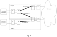
- Another method is to perform segmentation based on UE, as shown in Fig. 3 .
- the ports on the UE side and the UPF side are integrated as part of the bridge by the 5GS bridge and notified to the TSN TT, and then provided to the CNC for registration or modification of the TSN bridge.
- a complete 5GS system may be segmented into multiple TSN virtual bridges, and there are no interconnection ports between these multiple virtual TSN bridges, thus resulting in a system in which communication would otherwise be possible between 5GSs, after being segmented into virtual TSN bridges, not being able to connect in the CNC's view instead.
- the routes within the 5GS could have been used to calculate paths and forward messages, however, the CNC is not aware of these routes, resulting in the inability to perform path calculation, which would result in a much lower success rate of path calculation.
- the transmission latency of the 5GS system is not fixed, and the latency is related to the resources allocated by the system, and its span is relatively large.
- the CNC cannot directly sum up the latencies acquired on the link as before as a basis for judgment when performing path calculations. Therefore, it's important to provide an effective solution for path calculation of the 5GS-TSN-VB link.
- TSN-5GS QoS mapping provides details on how to perform the QoS mapping between TSN and 5GS, while being compliant with the input and output information required in TSN (fully centralized model). It also proposes a feedback approach in order to match the reported/exposed information to the TSN and the received configuration information from the CNC. In this way, the 5GS will configure connections internally only according to the needs and requirements.
- a document "Updates on Solution #18” proposes to update solution #18: QoS negotiation between 3GPP and TSN networks. It mainly focuses on 5GS virtual bridge information reporting and QoS profile generation for CP based architecture.
- WO 2018/015425 A1 discloses a system and method for determining a network path through a network that is managed by a software defined network (Ts SDN) controller incorporating time management.
- the SDN controller can determine that a data packet originating from a transmitting device and directed to a receiving device is associated with one of: time-sensitive, time-aware or best effort characteristic.
- the controller can then determine a network path for transport of the data packet from the transmitting device to the receiving device with a guaranteed end to end delay to satisfy the characteristic.
- the end to end delay considers latency through each layer the data packet transitions through after being conjured at an application layer of the transmitting device.
- the data packet is then transmitted from the transmitting device via the network path to the receiving device.
- a link path calculation method, device, and terminal device and a computer-readable storage medium are provided by the embodiments of the present disclosure, which are applicable to a 5GS-TSN-VB link, in order to enhance success rate of path calculation and improve user experience, to at least a certain extent.
- the embodiments of the present disclosure provide a link path calculation method applied to a 5GS-TSN-VB link, the link path calculation method including: acquiring a topology containing a TSN bridge, the TSN bridge including a 5GS TSN virtual bridge and a common TSN bridge; acquiring a latency parameter of a link of the TSN bridge; acquiring a minimum latency Tmin, achievable by the 5GS-TSN-VB as a 5GS, where UE connected to a listener is located at the 5GS-TSN-VB, and acquiring a maximum latency MaxLatency in service requirements; calculating an optimal path and determining the sum Tc of all link latencies on the optimal path; determining, according to the Tc, Tmin, and MaxLatency, a maximum latency Tmax tolerated by the 5GS-TSN-VB; determining an optimal value Tmax-O of the Tmax according to the Tmax, the Tmax-O being less than or equal to the Tmax and the Tmax-O being greater than zero; and
- Embodiments of the present disclosure also provide a link path calculation device, including: a first acquisition module configured to acquire a topology containing a TSN bridge, the TSN bridge including a 5GS TSN virtual bridge and a common TSN bridge; a second acquisition module configured to acquire a latency parameter of a link of the TSN bridge; a third acquisition module configured to acquire a minimum latency Tmin, achievable by the 5GS-TSN-VB as a 5GS where UE connected to a listener is located at the 5GS-TSN-VB, and acquire a maximum latency MaxLatency in service requirements; a first calculation module configured to calculate an optimal path and determine the sum Tc of all link latencies on the optimal path; a second calculation module configured to determine, according to the Tc, Tmin, and MaxLatency, a maximum latency Tmax tolerated by the 5GS-TSN-VB; a third calculation module configured to determine an optimal value Tmax-O of the Tmax according to the Tmax, the Tmax-O being less than
- Embodiments of the present disclosure also provide a link path calculation terminal device applied to a 5GS-TSN-VB link, the link path calculation terminal including: a processor, a memory and a communication bus, where the communication bus is configured to implement connection and communication between the processor and the memory; and the processor is configured to execute one or more computer programs stored in the memory to implement the link path calculation method as described in any one of the above.
- Embodiments of the present disclosure also provide a computer-readable storage medium storing one or more computer programs executable by one or more processors to implement the link path calculation method as described in any one of the above.
- the present disclosure provides a link path calculation method, device, and terminal device and a computer-readable storage medium.
- the link path calculation method through acquiring a topology of a TSN bridge including a 5GS TSN virtual bridge and a common TSN bridge; acquiring a latency parameter of a link of the TSN bridge, and a minimum latency Tmin, achievable by the 5GS-TSN-VB as a 5GS where UE connected to a listener is located the 5GS-TSN-VB, and acquiring a maximum latency MaxLatency in service requirements; calculating an optimal path and determining the sum Tc of all link latencies on the optimal path; determining, according to the Tc, Tmin, and MaxLatency, a maximum latency Tmax tolerated by the 5GS-TSN-VB; determining an optimal value Tmax-O of the Tmax according to the Tmax, the Tmax-O being less than or equal to the Tmax and the Tmax-O being greater than zero; and sending service flow
- a link path calculation method provided in this embodiment includes steps S401 to S407.
- a topology containing a TSN bridge is acquired.
- a latency parameter of a link of the TSN bridge is acquired.
- a minimum latency Tmin achievable by the 5GS-TSN-VB as a 5GS where UE connected to a listener is located, and a maximum latency MaxLatency in service requirements, are acquired.
- an optimal path is calculated and the sum Tc of all link latencies on the optimal path is determined.
- a maximum latency Tmax tolerated by the 5GS-TSN-VB is determined according to the Tc, Tmin, and MaxLatency.
- an optimal value Tmax-O of the Tmax is determined according to the Tmax, the Tmax-O being less than or equal to the Tmax and the Tmax-O being greater than zero.
- service flow information and the Tmax-O are sent as latency requirements to a 5GS system corresponding to the 5GS-TSN-VB, and the service flow information is sent to a corresponding TSN bridge in response to path calculation being successful.
- the event processing method is applied to a 5GS-TSN-VB link, where the TSN bridge includes a 5GS TSN virtual bridge and a common TSN bridge.
- the topology containing a TSN bridge may be acquired by a TSN entity such as CNC, CUC, End-Station, etc., where the topology may be acquired in an existing implementable manner, which is not limited in the embodiments of the present disclosure.
- the above-mentioned acquiring minimum latency Tmin, achievable by the 5GS-TSN-VB as a 5GS where UE connected to a receiver (listener) is located, and a maximum latency MaxLatency in service requirements, may be implemented using the relevant existing technology in the field, and is not limited here.
- all link latencies on the optimal path may be accumulated, and the resulting sum is Tc.
- the minimum latency Tmin achievable by the 5GS-TSN-VB as a 5GS where UE connected to the listener is located, may be configured by the user or the system, and a minimum value of the minimum latency Tmin may be 0.
- the link path calculation method in response to the presence of segmentation in the 5GS system, before acquiring a latency parameter of a link of the TSN bridge, the link path calculation method further includes: configuring a virtual fully connected 5GS-VL between segmented virtual TSN bridges; and acquiring a topology of the 5GS-VL; and the TSN bridge further includes the 5GS-VL.
- a virtual fully connected 5GS-VL may be configured between the segmented virtual TSN bridges, and then the topology of the TSN bridge including the virtual fully connected 5GS-VL may be acquired, where the TSN bridge includes a 5GS TSN virtual bridge, 5GS-VL and common TSN bridges.
- the common TSN bridge includes bridges in the TSN bridge other than the 5GS TSN virtual bridge and the 5GS-VL.
- the 5GS-VL may be a fully connected virtual connection 5GS-VL which is added between segmented TSN virtual bridges in the 5GS system, where each virtual connection has a determined latency that may be calculated and read through real internal routes, and these virtual connections may be utilized by TSN entities such as CNCs and used for path calculations.
- the method of segmentation includes, but is not limited to, the following two methods: UPF-based segmentation, and UE-based segmentation.
- policy function f(x,y) determined based on latency (x), tariff and/or resources (y) may be a policy function developed by the user based on conditions related to latency, tariff and/or resources.
- Tmax-O is equal to Tmax multiplied by a predetermined coefficient, which is a value greater than 0 and less than or equal to 1.
- the predetermined coefficient may be obtained by the user through trial calculations based on the tariff, resource usage and latency that the user can afford, or it may be determined by the user by building a calculation model between the tariff, resource occupation and latency.
- determining an optimal value Tmax-O of the Tmax according the Tmax includes: the Tmax-O being equal to a smaller one of latencies of the 5GS system in response to the latencies of the 5GS system being at least two discrete points.
- the above method is further described below by means of an embodiment. As shown in Fig. 5 , the method includes the steps S501 to S508.
- a virtual fully connected 5GS-VL is configured between segmented virtual TSN bridges.
- the CNC acquires a topology containing a 5GS TSN virtual bridge, a common TSN bridge and the virtual fully connected 5GS-VL.
- the CNC reads the latency parameter of each link.
- a minimum latency Tmin achievable by the 5GS-TSN-VB as a 5GS where UE connected to the listener is located, is read.
- the CNC calculates an optimal path and sums up all link latencies on the path as Tc.
- a maximum latency Tmax tolerated by the 5GS-TSN-VB is calculated according to Equation (1).
- an optimal value Tmax-O of the Tmax is selected according to the 5GS system and a policy.
- service flow information and the Tmax-O are sent as latency requirements to a 5GS system corresponding to the 5GS-TSN-VB, while the CNC successfully performs path calculation and sends the corresponding data to the corresponding bridge and virtual bridge.
- a protocol such as NETCONF
- the selection of the optimal value in S507 may be performed in the following two methods:
- Tmin may be configured, and the minimum value of Tmin may be configured to 0.
- MaxLatency is the maximum latency in the service requirements
- no segmentation is performed in the 5GS system, which exists only as a whole. In this case, during the selection and calculation of its latency, it is not necessary to consider adding a virtual fully connected 5GS-VL, and it is only necessary to calculate the 5GS TSN virtual bridge and the common TSN bridge.
- Fig. 6 illustrates an embodiment of the link path calculation method in the case where a 5GS system works as a whole without segmentation. As shown in Fig. 6 , the 5GS system serves as a whole TSN virtual bridge, where the dashed arrows are the calculation paths for the CNC.
- Tmax-O 15.2 ms is calculated and is sent to the 5GS system corresponding to 5GS-TSN-VB via NETCONF, while the CNC successfully performs path calculation and sends the corresponding data to the corresponding common bridge and virtual bridge.
- Fig. 7 illustrates an embodiment of the link path calculation method in the case where UPF-based segmentation is performed in the 5GS system.
- Fig. 7 there is a virtual connection 5GS-VL 1 configured between Bridge A and Bridge B, where the latency of this link may be acquired by the CNC, and messages may be forwarded between UPF-A and UPF-B.
- the path 701 calculated by the CNC contains a virtual link inside the 5GS system, from Bridge A to Bridge B.
- Tmax-O 11.2 ms is sent as the latency requirement to the 5GS system corresponding to 5GS-TSN-VB via NETCONF, while the CNC successfully performs path calculation and sends the corresponding data to the corresponding common bridge and virtual bridge.
- Fig. 8 illustrates an embodiment of the link path calculation method in the case where UPF-based segmentation is performed in the 5GS system.
- Fig. 8 there is a virtual connection 5GS-VL2 configured between Bridge A and Bridge B, where the latency of this link may be acquired by the CNC, and messages may be forwarded between UPF-A and UPF-B.
- the path 80 calculated by the CNC contains a virtual link inside the 5GS system, from Bridge A to Bridge B.
- Tmax-O 14 ms.
- Tmax-O 14 ms is sent as the latency requirement to the 5GS system corresponding to 5GS-TSN-VB via NETCONF, while the CNC successfully performs path calculation and sends the corresponding data to the corresponding common bridge and virtual bridge.
- the link path calculation method through acquiring a topology of a TSN bridge including a 5GS TSN virtual bridge and a common TSN bridge; acquiring a latency parameter of a link of the TSN bridge, and a minimum latency Tmin, achievable by the 5GS-TSN-VB as a 5GS where UE connected to a listener is located, and a maximum latency MaxLatency in service requirements; calculating an optimal path and determining the sum Tc of all link latencies on the optimal path; determining, according to the Tc, Tmin, and MaxLatency, a maximum latency Tmax tolerated by the 5GS-TSN-VB; determining an optimal value Tmax-O of the Tmax according to the Tmax, the Tmax-O being less than or equal to the Tmax and the Tmax-O being greater than zero; and sending service flow information and the Tmax-O as latency requirements to a 5GS system corresponding to the 5GS-TSN-VB, and sending the service flow information
- a fully connected virtual connection 5GS-VL is added between the segmented TSN virtual bridge, where the introduction of the 5GS-VL enables virtual link connections between the segmented virtual TSN bridges.
- a backward path calculation method is proposed based on the virtual connections, which can configure the optimal time requirement and resource occupation for virtual links within the 5GS TSN virtual bridge.
- the link path calculation device 900 includes a first acquisition module 901, a second acquisition module 902, a third acquisition module 903, a first calculation module 904, a second calculation module 905, a third calculation module 906 and a sending module 907.
- the event processing method is applied to a 5GS-TSN-VB link, where the TSN network bridge includes a 5GS TSN virtual bridge and a common TSN bridge.
- the topology containing a TSN bridge may be acquired by a TSN entity such as CNC, CUC, End-Station, etc., where the topology may be acquired in an existing implementable manner, which is not limited in the embodiments of the present disclosure.
- acquiring the minimum latency Tmin, achievable by the 5GS-TSN-VB as a 5GS where UE connected to a receiver (listener) is located, and a maximum latency MaxLatency in service requirements, may be implemented by utilizing the relevant existing technology in the field, and is not limited here.
- the method to determine the sum Tc of all link latencies on the optimal path may be understood as adding up all link latencies on the optimal path, and the resulting sum is Tc.
- the minimum latency Tmin achievable by the 5GS-TSN-VB as a 5GS where UE connected to the listener is located, may be configured by the user or the system, and the minimum value of the minimum latency Tmin may be 0.
- the link path calculation device in response to the presence of segmentation in the 5GS system, before acquiring a latency parameter of a link of the TSN bridge, the link path calculation device further includes a configuration module and a fourth acquisition module.
- the configuration module is configured to configure, before the second acquisition module acquires a latency parameter of a link of the TSN bridge, a virtual fully connected 5GS-VL between segmented virtual TSN bridges; and
- the fourth acquisition module is configured to acquire a topology of the 5GS-VL.
- the TSN bridge further includes the 5GS-VL.
- a virtual fully connected 5GS-VL may be configured between the segmented virtual TSN bridges, and then the topology of the TSN bridge including the virtual fully connected 5GS-VL may be acquired, where the TSN bridge includes a 5GS TSN virtual bridge, 5GS-VL and common TSN bridges.
- the common TSN bridge includes bridges in the TSN bridge other than the 5GS TSN virtual bridge and the 5GS-VL.
- the 5GS-VL may be a fully connected virtual connection 5GS-VL added between segmented TSN virtual bridges in the 5GS system, where each virtual connection has a determined latency that may be calculated and read through real internal routes, and these virtual connections may be utilized by the CNC and used for path calculations.
- the method of segmentation includes, but is not limited to, the following two methods: UPF-based segmentation, and UE-based segmentation.
- policy function f(x,y) determined based on latency (x), tariff and/or resources (y) may be a policy function developed by the user based on conditions related to latency, tariff and/or resources.
- Tmax-O is equal to Tmax multiplied by a predetermined coefficient, which is a value greater than 0 and less than or equal to 1.
- the predetermined coefficient may be obtained by the user through trial calculations based on the tariff, resource usage and latency that the user can afford, or it may be determined by the user by building a calculation model between the tariff, resource occupation and latency.
- the third calculation module determining an optimal value Tmax-O of the Tmax according to the Tmax includes: the Tmax-O being equal to a smaller one of latencies of the 5GS system in response to the latencies of the 5GS system being at least two discrete points.
- the link path calculation device through acquiring, by a first acquisition module, a topology of a TSN bridge including a 5GS TSN virtual bridge and a common TSN bridge; acquiring, by a second acquisition module, a latency parameter of a link of the TSN bridge, and acquiring, by a third acquisition module, a minimum latency Tmin, achievable by the 5GS-TSN-VB as a 5GS where UE connected to a listener is located, and a maximum latency MaxLatency in service requirements; calculating, by a first calculation module, an optimal path and determining the sum Tc of all link latencies on the optimal path; determining, by a second calculation module according to the Tc, Tmin, and MaxLatency, a maximum latency Tmax tolerated by the 5GS-TSN-VB; determining, by a third calculation module, an optimal value Tmax-O of the Tmax according to the Tmax, the Tmax-O being less than or equal to the Tmax and the
- a fully connected virtual connection 5GS-VL is added between the segmented TSN virtual bridge, where the introduction of the 5GS-VL enables virtual link connections between the segmented virtual TSN bridges.
- a backward path calculation method is proposed based on the virtual connections, which can configure the optimal time requirement and resource occupation for virtual links within the 5GS TSN virtual bridge.
- This embodiment provides a link path calculation terminal device which, as shown in Fig. 10 , includes a processor 1001, a memory 1003, and a communication bus 1002, where: the communication bus 1002 is configured to implement connection and communication between the processor 1001 and the memory 1003; and the processor 1001 is configured to execute one or more computer programs stored in memory 1003 to implement at least one step of the link path calculation method as described in the above embodiments.
- This embodiment provides a computer-readable storage medium that includes a volatile or non-volatile, removable or non-removable medium implemented in any method or technology for storing information, such as computer-readable instructions, data structures, computer program modules, or other data.
- the computer-readable storage medium includes, but is not limited to, random access memory (RAM), read-only memory (ROM), electrically erasable programmable read-only memory (EEPROM), flash memory or other memory technologies, compact disc read-only memory (CD-ROM), digital versatile disc (DVD) or other optical disc storage, cassettes, magnetic tapes, magnetic disc storage or other magnetic storage devices, or any other media that can be configured to store desired information and can be accessed by computers.
- the computer-readable storage medium in this embodiment may be used to store one or more computer programs executable by a processor to implement at least one step of the link path calculation method as described in the above embodiments.
- This embodiment also provides a computer program (or computer software) which may be distributed on a computer-readable medium and may be executed by a computing device to implement at least one step of the event processing method as described in the above embodiments; and in some cases, at least one step illustrated or described may be performed in an order different from that described in the above embodiments.
- a computer program or computer software
- This embodiment also provides a computer program product including a computer-readable device on which a computer program as illustrated above is stored.
- the computer-readable device may include the computer-readable storage medium as illustrated above.
- communication media typically contain computer-readable instructions, data structures, computer program modules or other data in a modulated data signal such as a carrier wave or other transmission mechanism, and may include any information delivery media. Therefore, the present disclosure is not limited to any particular combination of hardware and software.
- a topology of a TSN bridge including a 5GS TSN virtual bridge and a common TSN bridge; acquiring a latency parameter of a link of the TSN bridge, and a minimum latency Tmin that the 5GS-TSN-VB where UE connected to a listener is located can achieve as a 5GS and a maximum latency MaxLatency in service requirements; calculating an optimal path and determining the sum Tc of all link latencies on the optimal path; determining, according to the Tc, Tmin, and MaxLatency, a maximum latency Tmax tolerated by the 5GS-TSN-VB; determining an optimal value Tmax-O of the Tmax according to the Tmax, the Tmax-O being less than or equal to the Tmax and the Tmax-O being greater than zero; and sending service flow information and the Tmax-O as latency requirements to a 5GS system corresponding to the 5GS-TSN-VB, and sending the service
Landscapes
- Engineering & Computer Science (AREA)
- Computer Networks & Wireless Communication (AREA)
- Signal Processing (AREA)
- Data Exchanges In Wide-Area Networks (AREA)
Description
- Embodiments of the present disclosure relate to, but are not limited to, the field of network communications and, in particular to, but are not limited to, a link path calculation method, device, and terminal device, and a computer-readable storage medium.
- The 3rd Generation Partnership Project (3GPP) has determined the Service-based architecture (SBA) as the 5G unified infrastructure. The official name of the 5G System Architecture Standards Project is: the 5G System Architecture, or 5GS for short.
- When the 5GS is to support Time sensitive Network (TSN) requirements, the 5GS plans to emulate a TSN bridge to reduce the impact on other TSN entities (e.g. CNC, CUC, End-Station, etc.), while the 5GS is internally a black box to the outside and will not significantly alter the 5GS. The 5GS functions as a bridge for the TSN network and consists of ports on the User Plane Function (UPF) side, user plane tunnels between User Equipment (UE) and the UPF, ports on the UE/TT side, and interfaces between virtual bridges. For the TSN virtual bridge of the 5GS, the ports on the UPF/TT and UE/TT sides support the connection with the TSN network, and the UPF/TT and UE/TT are associated with each other by the PDU sessions inside the 5GS. The connection diagram is as shown in
Fig. 1 , where TT is TSN Translator and PDU is Protocol Data Unit. - For the convenience of management, the 5GS system may use multiple segmentation methods: in one of them, no segmentation is performed in the whole system and the whole system acts as a TSN virtual bridge, as shown in
Fig. 1 , while in the other, segmentation is performed based on each UPF, as shown inFig. 2 . Another method is to perform segmentation based on UE, as shown inFig. 3 . - After the segmentation, the ports on the UE side and the UPF side are integrated as part of the bridge by the 5GS bridge and notified to the TSN TT, and then provided to the CNC for registration or modification of the TSN bridge.
- However, when bridge division is performed in the 5GS, a complete 5GS system may be segmented into multiple TSN virtual bridges, and there are no interconnection ports between these multiple virtual TSN bridges, thus resulting in a system in which communication would otherwise be possible between 5GSs, after being segmented into virtual TSN bridges, not being able to connect in the CNC's view instead. The routes within the 5GS could have been used to calculate paths and forward messages, however, the CNC is not aware of these routes, resulting in the inability to perform path calculation, which would result in a much lower success rate of path calculation.
- Meanwhile, the transmission latency of the 5GS system is not fixed, and the latency is related to the resources allocated by the system, and its span is relatively large. In this case, the CNC cannot directly sum up the latencies acquired on the link as before as a basis for judgment when performing path calculations. Therefore, it's important to provide an effective solution for path calculation of the 5GS-TSN-VB link.
- A document "TSN-5GS QoS mapping" provides details on how to perform the QoS mapping between TSN and 5GS, while being compliant with the input and output information required in TSN (fully centralized model). It also proposes a feedback approach in order to match the reported/exposed information to the TSN and the received configuration information from the CNC. In this way, the 5GS will configure connections internally only according to the needs and requirements.
- A document "3rd Generation Partnership Project; Technical Specification Group Services and System Aspects; Study on enhancement of 5G System (5GS) for vertical and Local Area Network (LAN) services (Release 16)" is to study enhancements to 5GS that are required to fulfil Stage-1 service requirements in vertical domains defined in TS 22.261 and TS 22.104.
- A document "Updates on
Solution # 18" proposes to update solution #18: QoS negotiation between 3GPP and TSN networks. It mainly focuses on 5GS virtual bridge information reporting and QoS profile generation for CP based architecture. -
WO 2018/015425 A1 discloses a system and method for determining a network path through a network that is managed by a software defined network (Ts SDN) controller incorporating time management. The SDN controller can determine that a data packet originating from a transmitting device and directed to a receiving device is associated with one of: time-sensitive, time-aware or best effort characteristic. The controller can then determine a network path for transport of the data packet from the transmitting device to the receiving device with a guaranteed end to end delay to satisfy the characteristic. The end to end delay considers latency through each layer the data packet transitions through after being conjured at an application layer of the transmitting device. The data packet is then transmitted from the transmitting device via the network path to the receiving device. - The invention is defined in the appended independent claims. Embodiments representing particular realisations of the invention are defined in the dependent claims.
- A link path calculation method, device, and terminal device and a computer-readable storage medium are provided by the embodiments of the present disclosure, which are applicable to a 5GS-TSN-VB link, in order to enhance success rate of path calculation and improve user experience, to at least a certain extent.
- The embodiments of the present disclosure provide a link path calculation method applied to a 5GS-TSN-VB link, the link path calculation method including: acquiring a topology containing a TSN bridge, the TSN bridge including a 5GS TSN virtual bridge and a common TSN bridge; acquiring a latency parameter of a link of the TSN bridge; acquiring a minimum latency Tmin, achievable by the 5GS-TSN-VB as a 5GS, where UE connected to a listener is located at the 5GS-TSN-VB, and acquiring a maximum latency MaxLatency in service requirements; calculating an optimal path and determining the sum Tc of all link latencies on the optimal path; determining, according to the Tc, Tmin, and MaxLatency, a maximum latency Tmax tolerated by the 5GS-TSN-VB; determining an optimal value Tmax-O of the Tmax according to the Tmax, the Tmax-O being less than or equal to the Tmax and the Tmax-O being greater than zero; and sending service flow information and the Tmax-O as latency requirements to a 5GS system corresponding to the 5GS-TSN-VB, and sending the service flow information to a corresponding TSN bridge in response to path calculation being successful.
- Embodiments of the present disclosure also provide a link path calculation device, including: a first acquisition module configured to acquire a topology containing a TSN bridge, the TSN bridge including a 5GS TSN virtual bridge and a common TSN bridge; a second acquisition module configured to acquire a latency parameter of a link of the TSN bridge; a third acquisition module configured to acquire a minimum latency Tmin, achievable by the 5GS-TSN-VB as a 5GS where UE connected to a listener is located at the 5GS-TSN-VB, and acquire a maximum latency MaxLatency in service requirements; a first calculation module configured to calculate an optimal path and determine the sum Tc of all link latencies on the optimal path; a second calculation module configured to determine, according to the Tc, Tmin, and MaxLatency, a maximum latency Tmax tolerated by the 5GS-TSN-VB; a third calculation module configured to determine an optimal value Tmax-O of the Tmax according to the Tmax, the Tmax-O being less than or equal to the Tmax and the Tmax-O being greater than zero; and a sending module configured to send service flow information and the Tmax-O as latency requirements to a 5GS system corresponding to the 5GS-TSN-VB, and send the service flow information to a corresponding TSN bridge in response to path calculation being successful.
- Embodiments of the present disclosure also provide a link path calculation terminal device applied to a 5GS-TSN-VB link, the link path calculation terminal including: a processor, a memory and a communication bus, where the communication bus is configured to implement connection and communication between the processor and the memory; and the processor is configured to execute one or more computer programs stored in the memory to implement the link path calculation method as described in any one of the above.
- Embodiments of the present disclosure also provide a computer-readable storage medium storing one or more computer programs executable by one or more processors to implement the link path calculation method as described in any one of the above.
- The beneficial effects of the present disclosure: the present disclosure provides a link path calculation method, device, and terminal device and a computer-readable storage medium. With the link path calculation method, through acquiring a topology of a TSN bridge including a 5GS TSN virtual bridge and a common TSN bridge; acquiring a latency parameter of a link of the TSN bridge, and a minimum latency Tmin, achievable by the 5GS-TSN-VB as a 5GS where UE connected to a listener is located the 5GS-TSN-VB, and acquiring a maximum latency MaxLatency in service requirements; calculating an optimal path and determining the sum Tc of all link latencies on the optimal path; determining, according to the Tc, Tmin, and MaxLatency, a maximum latency Tmax tolerated by the 5GS-TSN-VB; determining an optimal value Tmax-O of the Tmax according to the Tmax, the Tmax-O being less than or equal to the Tmax and the Tmax-O being greater than zero; and sending service flow information and the Tmax-O as latency requirements to a 5GS system corresponding to the 5GS-TSN-VB, and sending the service flow information to a corresponding TSN bridge in response to path calculation being successful, an effective solution is provided for path calculation of a 5GS-TSN-VB link, which enhances the success rate of path calculation and improves user experience.
- Other features and corresponding beneficial effects of the present disclosure are explained in the subsequent description, and it should be understood that at least some of the beneficial effects become apparent from the description of the present disclosure.
- The invention is set out in the appended set of claims.
-
-
Fig. 1 is a schematic diagram of a 5GS virtual bridge provided in the background section of the present disclosure; -
Fig. 2 is a schematic diagram of UPF-based segmentation of a 5GS virtual bridge provided in the background section of the present disclosure; -
Fig. 3 is a schematic diagram of UE-based segmentation of a 5GS virtual bridge provided in the background section of the present disclosure; -
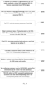
Fig. 4 is a flowchart of a link path calculation method provided in Embodiment I of the present disclosure; -
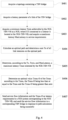
Fig. 5 is a flowchart of an implementation of a link path calculation method provided in Embodiment I of the present disclosure; -
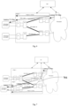
Fig. 6 is a schematic diagram of an implementation of another link path calculation method provided in Embodiment I of the present disclosure; -
Fig. 7 is a schematic diagram of an implementation of another link path calculation method provided in Embodiment I of the present disclosure; -
Fig. 8 is a schematic diagram of an implementation of another link path calculation method provided in Embodiment I of the present disclosure; -
Fig. 9 a schematic diagram of a link path calculation device provided in Embodiment II of the present disclosure; and -
Fig. 10 is a schematic diagram of a link path calculation terminal device provided in Embodiment III of the present disclosure. - In order to make the objective, technical schemes and advantages of the present disclosure more clearly understood, the embodiments of the present disclosure will be illustrated in detail by means of several embodiments in conjunction with the accompanying drawings. It should be understood that the particular embodiments described herein are only intended to explain the present disclosure, and are not intended to limit the present disclosure.
- Referring to
Fig. 4 , a link path calculation method provided in this embodiment includes steps S401 to S407. - At S401, a topology containing a TSN bridge is acquired.
- At S402, a latency parameter of a link of the TSN bridge is acquired.
- At S403, a minimum latency Tmin, achievable by the 5GS-TSN-VB as a 5GS where UE connected to a listener is located, and a maximum latency MaxLatency in service requirements, are acquired.
- At S404, an optimal path is calculated and the sum Tc of all link latencies on the optimal path is determined.
- At S405, a maximum latency Tmax tolerated by the 5GS-TSN-VB is determined according to the Tc, Tmin, and MaxLatency.
- At S406, an optimal value Tmax-O of the Tmax is determined according to the Tmax, the Tmax-O being less than or equal to the Tmax and the Tmax-O being greater than zero.
- At S407, service flow information and the Tmax-O are sent as latency requirements to a 5GS system corresponding to the 5GS-TSN-VB, and the service flow information is sent to a corresponding TSN bridge in response to path calculation being successful.
- In some embodiments, the event processing method is applied to a 5GS-TSN-VB link, where the TSN bridge includes a 5GS TSN virtual bridge and a common TSN bridge.
- In some embodiments, the topology containing a TSN bridge may be acquired by a TSN entity such as CNC, CUC, End-Station, etc., where the topology may be acquired in an existing implementable manner, which is not limited in the embodiments of the present disclosure.
- It should be noted that the above-mentioned acquiring minimum latency Tmin, achievable by the 5GS-TSN-VB as a 5GS where UE connected to a receiver (listener) is located, and a maximum latency MaxLatency in service requirements, may be implemented using the relevant existing technology in the field, and is not limited here.
- It should be noted that the calculation of the optimal path may be implemented using the relevant existing technology in the field, and is not limited here.
- To determine the sum Tc of all link latencies on the optimal path, all link latencies on the optimal path may be accumulated, and the resulting sum is Tc.
- It should be noted that the minimum latency Tmin, achievable by the 5GS-TSN-VB as a 5GS where UE connected to the listener is located, may be configured by the user or the system, and a minimum value of the minimum latency Tmin may be 0.
- In some embodiments, in response to the presence of segmentation in the 5GS system, before acquiring a latency parameter of a link of the TSN bridge, the link path calculation method further includes: configuring a virtual fully connected 5GS-VL between segmented virtual TSN bridges; and acquiring a topology of the 5GS-VL; and the TSN bridge further includes the 5GS-VL.
- It should be noted that in response to the presence of segmentation in the 5GS system, a virtual fully connected 5GS-VL may be configured between the segmented virtual TSN bridges, and then the topology of the TSN bridge including the virtual fully connected 5GS-VL may be acquired, where the TSN bridge includes a 5GS TSN virtual bridge, 5GS-VL and common TSN bridges. It should be noted that the common TSN bridge includes bridges in the TSN bridge other than the 5GS TSN virtual bridge and the 5GS-VL.
- In some embodiments, the 5GS-VL may be a fully connected virtual connection 5GS-VL which is added between segmented TSN virtual bridges in the 5GS system, where each virtual connection has a determined latency that may be calculated and read through real internal routes, and these virtual connections may be utilized by TSN entities such as CNCs and used for path calculations.
- In some embodiments, the method of segmentation includes, but is not limited to, the following two methods: UPF-based segmentation, and UE-based segmentation.
- It should be noted that those having ordinary skills in the art may also use other existing methods to implement segmentation of a 5GS system, and after adding a fully connected virtual connection 5GS-VL between the segmented TSN virtual bridges, link management and path calculation may also be performed in the method provided in the embodiments of the present disclosure.
- In some embodiments, determining, according to the Tc, Tmin, and MaxLatency, a maximum latency Tmax tolerated by the 5GS-TSN-VB includes: Tmax = MaxLatency - Tc + Tmin.
- In some embodiments, determining an optimal value Tmax-O of the Tmax according the Tmax includes: determining a policy function f(x,y) according to latency (x), tariff and/or resource (y), the f(x,y) being less than or equal to 1; and Tmax-O = f(x,y) * Tmax.
- It should be noted that the above-mentioned policy function f(x,y) determined based on latency (x), tariff and/or resources (y) may be a policy function developed by the user based on conditions related to latency, tariff and/or resources.
- In some embodiments, Tmax-O is equal to Tmax multiplied by a predetermined coefficient, which is a value greater than 0 and less than or equal to 1. The predetermined coefficient may be obtained by the user through trial calculations based on the tariff, resource usage and latency that the user can afford, or it may be determined by the user by building a calculation model between the tariff, resource occupation and latency.
- In some embodiments, determining an optimal value Tmax-O of the Tmax according the Tmax includes: the Tmax-O being equal to a smaller one of latencies of the 5GS system in response to the latencies of the 5GS system being at least two discrete points.
- For ease of understanding, the above method is further described below by means of an embodiment. As shown in
Fig. 5 , the method includes the steps S501 to S508. - At S501, in response to the presence of segmentation in the 5GS system, a virtual fully connected 5GS-VL is configured between segmented virtual TSN bridges.
- At S502, the CNC acquires a topology containing a 5GS TSN virtual bridge, a common TSN bridge and the virtual fully connected 5GS-VL.
- At S503, the CNC reads the latency parameter of each link.
- At S504, a minimum latency Tmin, achievable by the 5GS-TSN-VB as a 5GS where UE connected to the listener is located, is read.
- At S505, the CNC calculates an optimal path and sums up all link latencies on the path as Tc.
- At S506, a maximum latency Tmax tolerated by the 5GS-TSN-VB is calculated according to Equation (1).
- At S507, an optimal value Tmax-O of the Tmax is selected according to the 5GS system and a policy.
- At S508, by configuring a protocol, such as NETCONF, service flow information and the Tmax-O are sent as latency requirements to a 5GS system corresponding to the 5GS-TSN-VB, while the CNC successfully performs path calculation and sends the corresponding data to the corresponding bridge and virtual bridge.
- It should be noted that the equation in S506 is shown as follows:

- The selection of the optimal value in S507 may be performed in the following two methods:
- (1) An optimal value less than Tmax is selected according to a certain policy (taking into consideration the combination of latency and tariff/resources);

- (2) In response to the latencies of the radio system being discrete points T[ t0 , t1 , t2 ,... tn ], where t0 <t1 <t2 ...<tn, then a discrete latency value is selected for Tmax-O, and in response to tm ≤ Tmax-O< tm+1 being satisfied,

- It should be noted that the value of Tmin may be configured, and the minimum value of Tmin may be configured to 0. MaxLatency is the maximum latency in the service requirements
- In some embodiments, no segmentation is performed in the 5GS system, which exists only as a whole. In this case, during the selection and calculation of its latency, it is not necessary to consider adding a virtual fully connected 5GS-VL, and it is only necessary to calculate the 5GS TSN virtual bridge and the common TSN bridge.
-
Fig. 6 illustrates an embodiment of the link path calculation method in the case where a 5GS system works as a whole without segmentation. As shown inFig. 6 , the 5GS system serves as a whole TSN virtual bridge, where the dashed arrows are the calculation paths for the CNC. Assuming that the link latency on the left side of the 5GS of the optimal path calculated in the figure is T1 = 5 ms, and on the right side the link latency is T2 = 6 ms, and in the service requirements, MaxLatency = 26 ms, and Tmin = 4 ms, then Tmax = MaxLatency - (T1 + T2) + Tmin = 19 ms is calculated according to Equation (1), and then the optimal value Tmax-O is calculated according to Equation (2). Assuming that the policy function f(x,y) = 0.8, then Tmax-O = 15.2 ms is calculated and is sent to the 5GS system corresponding to 5GS-TSN-VB via NETCONF, while the CNC successfully performs path calculation and sends the corresponding data to the corresponding common bridge and virtual bridge. -
Fig. 7 illustrates an embodiment of the link path calculation method in the case where UPF-based segmentation is performed in the 5GS system. As shown inFig. 7 , there is a virtual connection 5GS-VL 1 configured between Bridge A and Bridge B, where the latency of this link may be acquired by the CNC, and messages may be forwarded between UPF-A and UPF-B. Thepath 701 calculated by the CNC contains a virtual link inside the 5GS system, from Bridge A to Bridge B. Assuming that the link latency on the left side of the 5GS of the optimal path calculated in the figure is T1 = 5 ms, and on the right side the link latency is T2 = 6 ms, and in the service requirements, MaxLatency = 26 ms, Tmin = 4 ms, and the latency of 5GS-VL 1 isTv 1 = 5 ms, then Tmax = MaxLatency - (T1 + T2 + Tv1) + Tmin = 14 ms is calculated according to Equation (1), and then the optimal value Tmax-O is calculated according to Equation (2). Assuming that the policy function f(x,y) = 0.8, then Tmax-O = 11.2 ms is calculated. At this time, Tmax-O = 11.2 ms is sent as the latency requirement to the 5GS system corresponding to 5GS-TSN-VB via NETCONF, while the CNC successfully performs path calculation and sends the corresponding data to the corresponding common bridge and virtual bridge. -
Fig. 8 illustrates an embodiment of the link path calculation method in the case where UPF-based segmentation is performed in the 5GS system. As shown inFig. 8 , there is a virtual connection 5GS-VL2 configured between Bridge A and Bridge B, where the latency of this link may be acquired by the CNC, and messages may be forwarded between UPF-A and UPF-B. The path 80 calculated by the CNC contains a virtual link inside the 5GS system, from Bridge A to Bridge B. Assuming that the link latency on the left side of the 5GS of the optimal path calculated in the figure is T1 = 5 ms, and on the right side the link latency is T2 = 6 ms, and in the service requirements, MaxLatency = 26 ms, Tmin = 4 ms, and the latency of 5GS-VL 2 is Tv2= 5ms, then Tmax = MaxLatency - (T1 + T2 + Tv2) + Tmin = 14ms is calculated according to Equation (1), and then the optimal value Tmax-O is calculated according to Equation (3). Assuming that the latencies are discrete points T[10 ms, 12 ms, 14 ms, 16 ms, ... 40 ms], and since 14 ms ≤ 14 ms < 16 ms, Tmax-O = 14 ms. At this time, Tmax-O = 14 ms is sent as the latency requirement to the 5GS system corresponding to 5GS-TSN-VB via NETCONF, while the CNC successfully performs path calculation and sends the corresponding data to the corresponding common bridge and virtual bridge. - It should be noted that the UE-based segmentation calculation method is similar to that in the above embodiments and will not be repeated here.
- With the link path calculation method proposed in the embodiment of the present disclosure, through acquiring a topology of a TSN bridge including a 5GS TSN virtual bridge and a common TSN bridge; acquiring a latency parameter of a link of the TSN bridge, and a minimum latency Tmin, achievable by the 5GS-TSN-VB as a 5GS where UE connected to a listener is located, and a maximum latency MaxLatency in service requirements; calculating an optimal path and determining the sum Tc of all link latencies on the optimal path; determining, according to the Tc, Tmin, and MaxLatency, a maximum latency Tmax tolerated by the 5GS-TSN-VB; determining an optimal value Tmax-O of the Tmax according to the Tmax, the Tmax-O being less than or equal to the Tmax and the Tmax-O being greater than zero; and sending service flow information and the Tmax-O as latency requirements to a 5GS system corresponding to the 5GS-TSN-VB, and sending the service flow information to a corresponding TSN bridge in response to path calculation being successful, the internal paths of the 5GS system are effectively utilized, which greatly increases the success rate of path calculation and effectively balances the contradiction between tariff/resources and latency, and improves the user experience.
- In response to the presence of segmentation in the 5GS system, a fully connected virtual connection 5GS-VL is added between the segmented TSN virtual bridge, where the introduction of the 5GS-VL enables virtual link connections between the segmented virtual TSN bridges. At the same time, a backward path calculation method is proposed based on the virtual connections, which can configure the optimal time requirement and resource occupation for virtual links within the 5GS TSN virtual bridge.
- This embodiment provides a link path calculation device. As shown in
Fig. 9 , the linkpath calculation device 900 includes afirst acquisition module 901, asecond acquisition module 902, athird acquisition module 903, a first calculation module 904, a second calculation module 905, a third calculation module 906 and a sendingmodule 907. - The
first acquisition module 901 is configured to acquire a topology containing a TSN bridge, the TSN bridge including a 5GS TSN virtual bridge and a common TSN bridge; - The
second acquisition module 902 is configured to acquire a latency parameter of a link of the TSN bridge; - The
third acquisition module 903 is configured to acquire a minimum latency Tmin, achievable by the 5GS-TSN-VB as a 5GS where UE connected to a listener is located, and a maximum latency MaxLatency in service requirements; - The first calculation module 904 is configured to calculate an optimal path and determine the sum Tc of all link latencies on the optimal path;
- The second calculation module 905 is configured to determine, according to the Tc, Tmin, and MaxLatency, a maximum latency Tmax tolerated by the 5GS-TSN-VB;
- The third calculation module 906 is configured to determine an optimal value Tmax-O of the Tmax according to the Tmax, the Tmax-O being less than or equal to the Tmax and the Tmax-O being greater than zero; and
- The sending
module 907 is configured to send service flow information and the Tmax-O as latency requirements to a 5GS system corresponding to the 5GS-TSN-VB, and send the service flow information to a corresponding TSN bridge in response to path calculation being successful. - In some embodiments, the event processing method is applied to a 5GS-TSN-VB link, where the TSN network bridge includes a 5GS TSN virtual bridge and a common TSN bridge.
- In some embodiments, the topology containing a TSN bridge may be acquired by a TSN entity such as CNC, CUC, End-Station, etc., where the topology may be acquired in an existing implementable manner, which is not limited in the embodiments of the present disclosure.
- It should be noted that acquiring the minimum latency Tmin, achievable by the 5GS-TSN-VB as a 5GS where UE connected to a receiver (listener) is located, and a maximum latency MaxLatency in service requirements, may be implemented by utilizing the relevant existing technology in the field, and is not limited here.
- It should be noted that the calculation of the optimal path may be implemented using the relevant existing technology in the field, and is not limited here.
- The method to determine the sum Tc of all link latencies on the optimal path may be understood as adding up all link latencies on the optimal path, and the resulting sum is Tc.
- It should be noted that the minimum latency Tmin, achievable by the 5GS-TSN-VB as a 5GS where UE connected to the listener is located, may be configured by the user or the system, and the minimum value of the minimum latency Tmin may be 0.
- In some embodiments, in response to the presence of segmentation in the 5GS system, before acquiring a latency parameter of a link of the TSN bridge, the link path calculation device further includes a configuration module and a fourth acquisition module.
- The configuration module is configured to configure, before the second acquisition module acquires a latency parameter of a link of the TSN bridge, a virtual fully connected 5GS-VL between segmented virtual TSN bridges; and
The fourth acquisition module is configured to acquire a topology of the 5GS-VL. - In the configuration in which the second acquisition module acquires the latency parameter of the link of the TSN bridge, the TSN bridge further includes the 5GS-VL.
- It should be noted that in response to the presence of segmentation in the 5GS system, a virtual fully connected 5GS-VL may be configured between the segmented virtual TSN bridges, and then the topology of the TSN bridge including the virtual fully connected 5GS-VL may be acquired, where the TSN bridge includes a 5GS TSN virtual bridge, 5GS-VL and common TSN bridges. It should be noted that the common TSN bridge includes bridges in the TSN bridge other than the 5GS TSN virtual bridge and the 5GS-VL.
- In some embodiments, the 5GS-VL may be a fully connected virtual connection 5GS-VL added between segmented TSN virtual bridges in the 5GS system, where each virtual connection has a determined latency that may be calculated and read through real internal routes, and these virtual connections may be utilized by the CNC and used for path calculations.
- In some embodiments, the method of segmentation includes, but is not limited to, the following two methods: UPF-based segmentation, and UE-based segmentation.
- It should be noted that those having ordinary skills in the art may also use other existing methods to implement segmentation of a 5GS system, and after adding a fully connected virtual connection 5GS-VL between the segmented TSN virtual bridges, link management and path calculation may also be performed in the method provided in the embodiments of the present disclosure.
- In some embodiments, the second calculation module determining, according to the Tc, Tmin, and MaxLatency, a maximum latency Tmax tolerated by the 5GS-TSN-VB includes: Tmax = MaxLatency - Tc + Tmin.
- In some embodiments, the third calculation module determining an optimal value Tmax-O of the Tmax according to the Tmax includes: determining a policy function f(x,y) according to latency (x), tariff and/or resource (y), the f(x,y) being less than or equal to 1; and Tmax-O = f(x,y) * Tmax.
- It should be noted that the above-mentioned policy function f(x,y) determined based on latency (x), tariff and/or resources (y) may be a policy function developed by the user based on conditions related to latency, tariff and/or resources.
- In some embodiments, Tmax-O is equal to Tmax multiplied by a predetermined coefficient, which is a value greater than 0 and less than or equal to 1. The predetermined coefficient may be obtained by the user through trial calculations based on the tariff, resource usage and latency that the user can afford, or it may be determined by the user by building a calculation model between the tariff, resource occupation and latency.
- In some embodiments, the third calculation module determining an optimal value Tmax-O of the Tmax according to the Tmax includes: the Tmax-O being equal to a smaller one of latencies of the 5GS system in response to the latencies of the 5GS system being at least two discrete points.
- With the link path calculation device proposed in the embodiment of the present disclosure, through acquiring, by a first acquisition module, a topology of a TSN bridge including a 5GS TSN virtual bridge and a common TSN bridge; acquiring, by a second acquisition module, a latency parameter of a link of the TSN bridge, and acquiring, by a third acquisition module, a minimum latency Tmin, achievable by the 5GS-TSN-VB as a 5GS where UE connected to a listener is located, and a maximum latency MaxLatency in service requirements; calculating, by a first calculation module, an optimal path and determining the sum Tc of all link latencies on the optimal path; determining, by a second calculation module according to the Tc, Tmin, and MaxLatency, a maximum latency Tmax tolerated by the 5GS-TSN-VB; determining, by a third calculation module, an optimal value Tmax-O of the Tmax according to the Tmax, the Tmax-O being less than or equal to the Tmax and the Tmax-O being greater than zero; and sending, by a sending module, service flow information and the Tmax-O as latency requirements to a 5GS system corresponding to the 5GS-TSN-VB, and sends the service flow information to a corresponding TSN bridge in response to path calculation being successful, the internal paths of the 5GS system are effectively utilized, which greatly increases the success rate of path calculation and effectively balances the contradiction between tariff/resources and latency, and improves the user experience.
- In response to the presence of segmentation in the 5GS system, a fully connected virtual connection 5GS-VL is added between the segmented TSN virtual bridge, where the introduction of the 5GS-VL enables virtual link connections between the segmented virtual TSN bridges. At the same time, a backward path calculation method is proposed based on the virtual connections, which can configure the optimal time requirement and resource occupation for virtual links within the 5GS TSN virtual bridge.
- This embodiment provides a link path calculation terminal device which, as shown in
Fig. 10 , includes aprocessor 1001, amemory 1003, and acommunication bus 1002, where: thecommunication bus 1002 is configured to implement connection and communication between theprocessor 1001 and thememory 1003; and theprocessor 1001 is configured to execute one or more computer programs stored inmemory 1003 to implement at least one step of the link path calculation method as described in the above embodiments. - This embodiment provides a computer-readable storage medium that includes a volatile or non-volatile, removable or non-removable medium implemented in any method or technology for storing information, such as computer-readable instructions, data structures, computer program modules, or other data. The computer-readable storage medium includes, but is not limited to, random access memory (RAM), read-only memory (ROM), electrically erasable programmable read-only memory (EEPROM), flash memory or other memory technologies, compact disc read-only memory (CD-ROM), digital versatile disc (DVD) or other optical disc storage, cassettes, magnetic tapes, magnetic disc storage or other magnetic storage devices, or any other media that can be configured to store desired information and can be accessed by computers.
- The computer-readable storage medium in this embodiment may be used to store one or more computer programs executable by a processor to implement at least one step of the link path calculation method as described in the above embodiments.
- This embodiment also provides a computer program (or computer software) which may be distributed on a computer-readable medium and may be executed by a computing device to implement at least one step of the event processing method as described in the above embodiments; and in some cases, at least one step illustrated or described may be performed in an order different from that described in the above embodiments.
- It should be understood that in some cases, at least one step illustrated or described may be performed in an order different from that described in the above embodiments.
- This embodiment also provides a computer program product including a computer-readable device on which a computer program as illustrated above is stored. In this embodiment, the computer-readable device may include the computer-readable storage medium as illustrated above.
- As can be seen, it should be understood by those having ordinary skills in the art that all or some of the steps in the methods disclosed above, functional modules/units in the systems and devices disclosed above may be implemented as software (which may be implemented by computer program code executable by a computing device), firmware, hardware, and appropriate combinations thereof. In the hardware implementation, the division between functional modules/units mentioned in the above description does not necessarily correspond to the division of physical components; for example, a physical component may have multiple functions, or a function or step may be performed cooperatively by several physical components. Some or all of the physical components may be implemented as software executed by a processor, such as a central processing unit, a digital signal processor or a microprocessor, or as hardware, or as an integrated circuit, such as an application specific integrated circuit.
- Furthermore, it is well known to those having ordinary skills in the art that communication media typically contain computer-readable instructions, data structures, computer program modules or other data in a modulated data signal such as a carrier wave or other transmission mechanism, and may include any information delivery media. Therefore, the present disclosure is not limited to any particular combination of hardware and software.
- The foregoing is a detailed description of several embodiments of the present disclosure in conjunction with particular implementations, and implementations of the present disclosure should not be construed as being limited to the description. For those having ordinary skills in the art to which the present disclosure pertains, several simple deductions or substitutions can be made, the scope of the invention being defined solely by the appended claims.
- Based on the link path calculation method provided in the above embodiments of the present disclosure, through acquiring a topology of a TSN bridge including a 5GS TSN virtual bridge and a common TSN bridge; acquiring a latency parameter of a link of the TSN bridge, and a minimum latency Tmin that the 5GS-TSN-VB where UE connected to a listener is located can achieve as a 5GS and a maximum latency MaxLatency in service requirements; calculating an optimal path and determining the sum Tc of all link latencies on the optimal path; determining, according to the Tc, Tmin, and MaxLatency, a maximum latency Tmax tolerated by the 5GS-TSN-VB; determining an optimal value Tmax-O of the Tmax according to the Tmax, the Tmax-O being less than or equal to the Tmax and the Tmax-O being greater than zero; and sending service flow information and the Tmax-O as latency requirements to a 5GS system corresponding to the 5GS-TSN-VB, and sending the service flow information to a corresponding TSN bridge in response to path calculation being successful, an effective solution is provided for path calculation of a 5GS-TSN-VB link, which enhances the success rate of path calculation.
Claims (14)
- A link path calculation method applied to a 5G System Architecture-Time sensitive Network-Virtual Bridge, 5GS-TSN-VB link, comprisingacquiring a topology containing a TSN bridge, the TSN bridge comprising a 5GS TSN virtual bridge and a TSN common bridge (S401);acquiring a latency parameter of a link of the TSN bridge (S402);acquiring a minimum latency Tmin achievable by the 5GS-TSN-VB as a 5GS, wherein UE connected to a listener is located at the 5GS-TSN-VB; and acquiring a maximum latency MaxLatency in service requirements (S403);calculating an optimal path and determining a sum Tc of all link latencies on the optimal path (S404);determining, according to the Tc, Tmin, and MaxLatency, a maximum latency Tmax tolerated by the 5GS-TSN-VB (S405);characterised by determining an optimal value Tmax-O of the Tmax according to the Tmax, the Tmax-O being less than or equal to the Tmax and the Tmax-O being greater than zero (S406); andsending service flow information and the Tmax-O as latency requirements to a 5GS system corresponding to the 5GS-TSN-VB, and sending the service flow information to the TSN bridge corresponding to the successfully calculated path in response to path calculation being successful (S407).
- The link path calculation method of claim 1, in response to a presence of segmentation in the 5GS system, before acquiring a latency parameter of a link of the TSN bridge, further comprising:configuring a virtual fully connected 5GS-VL between segmented virtual TSN bridges; andacquiring a topology of the 5GS-VL;wherein the TSN bridge further comprises the 5GS-VL.
- The link path calculation method of claim 2, wherein the segmentation comprises at least one of: UPF-based segmentation, or UE-based segmentation.
- The link path calculation method of any one of claims 1 to 3, wherein determining, according to the Tc, Tmin, and MaxLatency, a maximum latency Tmax tolerated by the 5GS-TSN-VB comprises:

- The link path calculation method of claim 4, wherein determining an optimal value Tmax-O of the Tmax according to the Tmax comprises:
determining a policy function f(x,y) according to latency (x), tariff and resource (y), the f(x,y) being less than or equal to 1; and
- The link path calculation method of claim 4, wherein determining an optimal value Tmax-O of the Tmax according to the Tmax comprises:
determining a policy function f(x,y) according to latency (x), tariff or resource (y), the f(x,y) being less than or equal to 1; and
- The link path calculation method of claim 4, wherein determining an optimal value Tmax-O of the Tmax according to the Tmax comprises:
the Tmax-O being equal to a smaller one of latencies of the 5GS system in response to the latencies of the 5GS system being at least two discrete points. - A link path calculation device (900), comprisinga first acquisition module (901) configured to acquire a topology containing a TSN bridge, the TSN bridge comprising a 5GS TSN virtual bridge and a TSN common bridge;a second acquisition module (902) configured to acquire a latency parameter of a link of the TSN bridge;a third acquisition module (903) configured to acquire a minimum latency Tmin achievable by the 5G System Architecture-Time sensitive Network-Virtual Bridge, 5GS-TSN-VB, as a 5GS, wherein UE connected to a listener is located at the 5GS-TSN-VB, and a maximum latency MaxLatency in service requirements;a first calculation module (904) configured to calculate an optimal path and determine a sum Tc of all link latencies on the optimal path;a second calculation module (905) configured to determine, according to the Tc, Tmin, and MaxLatency, a maximum latency Tmax tolerated by the 5GS-TSN-VB;characterised by a third calculation module (906) configured to determine an optimal value Tmax-O of the Tmax according to the Tmax, the Tmax-O being less than or equal to the Tmax and the Tmax-O being greater than zero; anda sending module (907) configured to send service flow information and the Tmax-O as latency requirements to a 5GS system corresponding to the 5GS-TSN-VB, and send the service flow information to the TSN bridge corresponding to the successfully calculated path in response to path calculation being successful.
- The link path calculation device (900) of claim 8, in response to a presence of segmentation in the 5GS system, further comprising:a configuration module configured to configure, before the second acquisition module (902) acquires a latency parameter of a link of the TSN bridge, a virtual fully connected 5GS-VL between segmented virtual TSN bridges; anda fourth acquisition module configured to acquire a topology of the 5GS-VL;wherein in the configuration in which the second acquisition module (902) acquires the latency parameter of the link of the TSN bridge, the TSN bridge further comprises the 5GS-VL.
- The link path calculation device (900) of claim 9, wherein the segmentation comprises at least one of: UPF-based segmentation, or UE-based segmentation.
- The link path calculation device (900) of any one of claims 8 to 10, wherein the second calculation module (905) is configured to:
determine, according to the Tc, Tmin, and MaxLatency, a maximum latency Tmax tolerated by the 5GS-TSN-VB, by adopting Tmax = MaxLatency - Tc + Tmin. - The link path calculation device (900) of claim 11, wherein the third calculation module (906) is configured to:
determine an optimal value Tmax-O of the Tmax according to the Tmax, by adopting Tmax-O = f(x,y) * Tmax, where f(x,y) is a policy function f(x,y) determined according to latency (x), tariff and resource (y), and f(x,y) is less than or equal to 1. - The link path calculation device (900) of claim 11, wherein the third calculation module (906) is configured to:
determine an optimal value Tmax-O of the Tmax according to the Tmax, wherein the Tmax-O is equal to a smaller one of latencies of the 5GS system in response to the latencies of the 5GS system being at least two discrete points. - A computer-readable storage medium storing one or more computer programs executable by one or more processors to implement the link path calculation method of any one of claims 1 to 7.
Applications Claiming Priority (2)
| Application Number | Priority Date | Filing Date | Title |
|---|---|---|---|
| CN201910770799.5A CN112422432B (en) | 2019-08-20 | 2019-08-20 | Link path calculation method, device, terminal and computer readable storage medium |
| PCT/CN2020/101952 WO2021031744A1 (en) | 2019-08-20 | 2020-07-14 | Link path calculation method, apparatus, terminal and computer-readable storage medium |
Publications (3)
| Publication Number | Publication Date |
|---|---|
| EP4007223A1 EP4007223A1 (en) | 2022-06-01 |
| EP4007223A4 EP4007223A4 (en) | 2022-09-28 |
| EP4007223B1 true EP4007223B1 (en) | 2024-12-18 |
Family
ID=74660472
Family Applications (1)
| Application Number | Title | Priority Date | Filing Date |
|---|---|---|---|
| EP20854158.1A Active EP4007223B1 (en) | 2019-08-20 | 2020-07-14 | Link path calculation method, apparatus, terminal and computer-readable storage medium |
Country Status (5)
| Country | Link |
|---|---|
| US (1) | US12101243B2 (en) |
| EP (1) | EP4007223B1 (en) |
| CN (1) | CN112422432B (en) |
| ES (1) | ES3004867T3 (en) |
| WO (1) | WO2021031744A1 (en) |
Families Citing this family (1)
| Publication number | Priority date | Publication date | Assignee | Title |
|---|---|---|---|---|
| CN113747564B (en) * | 2021-09-07 | 2023-03-24 | 中国电信股份有限公司 | Time delay control method, system, device, storage medium and electronic equipment |
Family Cites Families (11)
| Publication number | Priority date | Publication date | Assignee | Title |
|---|---|---|---|---|
| ES2987476T3 (en) * | 2016-07-19 | 2024-11-15 | Schneider Electric Ind Sas | Time-sensitive software-defined networks |
| CN109845201A (en) | 2016-08-08 | 2019-06-04 | 西门子股份公司 | Method, software agent, networking device and SDN controller for software-defined networking of cyber-physical networks in different technical fields, especially industrial automation networks |
| US20180184438A1 (en) * | 2016-12-28 | 2018-06-28 | Intel Corporation | Persistent scheduling and forwarding while receiving in wireless time sensitive networks |
| CN107172710B (en) * | 2017-04-23 | 2019-12-06 | 西安电子科技大学 | resource allocation and service access control method based on virtual subnet |
| EP3448000A1 (en) * | 2017-08-23 | 2019-02-27 | Siemens Aktiengesellschaft | Method for generating a unique addressing id for a data stream of an application in a tsn-compliant network and apparatus for same |
| CN110120878B (en) * | 2018-02-05 | 2020-10-23 | 华为技术有限公司 | Method and apparatus for obtaining link quality |
| EP3831014A1 (en) * | 2018-08-13 | 2021-06-09 | Nokia Solutions and Networks GmbH & Co. KG | Supporting the fulfilment of e2e qos requirements in tsn-3gpp network integration |
| EP3837815A1 (en) * | 2018-08-14 | 2021-06-23 | Nokia Technologies Oy | Signalling of deterministic system capabilities depending on absolute transmission time (tsn, detnet, etc.) |
| EP3837809B1 (en) * | 2018-08-14 | 2026-04-08 | Nokia Solutions and Networks Oy | Mutual 3gpp-tsn qos adaption and shaping |
| US11489769B2 (en) * | 2019-03-20 | 2022-11-01 | Cisco Technology, Inc. | Virtualized radio access network architecture for applications requiring a time sensitive network |
| WO2021002873A1 (en) * | 2019-07-03 | 2021-01-07 | Nokia Technologies Oy | Selective packet duplication or alternative packet transmission based on survival time |
-
2019
- 2019-08-20 CN CN201910770799.5A patent/CN112422432B/en active Active
-
2020
- 2020-07-14 US US17/635,912 patent/US12101243B2/en active Active
- 2020-07-14 ES ES20854158T patent/ES3004867T3/en active Active
- 2020-07-14 WO PCT/CN2020/101952 patent/WO2021031744A1/en not_active Ceased
- 2020-07-14 EP EP20854158.1A patent/EP4007223B1/en active Active
Also Published As
| Publication number | Publication date |
|---|---|
| WO2021031744A1 (en) | 2021-02-25 |
| ES3004867T3 (en) | 2025-03-13 |
| US20220286380A1 (en) | 2022-09-08 |
| EP4007223A1 (en) | 2022-06-01 |
| CN112422432B (en) | 2023-06-20 |
| EP4007223A4 (en) | 2022-09-28 |
| US12101243B2 (en) | 2024-09-24 |
| CN112422432A (en) | 2021-02-26 |
Similar Documents
| Publication | Publication Date | Title |
|---|---|---|
| US20220132413A1 (en) | Network Slice Management Method and Related Apparatus | |
| CN114731333B (en) | Method, system and computer readable medium for providing guaranteed traffic bandwidth for services at an intermediate proxy node | |
| EP4024778B1 (en) | Method for determining required bandwidth for data stream transmission, and devices and system | |
| EP1623536B1 (en) | Method for the distribution of a network traffic according to sla and qos parameters | |
| US11258717B2 (en) | Method for sending service packet, network device, and system | |
| KR101938455B1 (en) | Method and apparatus for perforiming dynamic edge computing | |
| EP3585095A1 (en) | Method for controlling quality of service, and device, smf, upf, ue, pcf and an therefor | |
| WO2021139696A1 (en) | Method, apparatus and system for sending report information | |
| CN114827007B (en) | Computing power-aware routing method, device, routing node, and client device | |
| US10999882B2 (en) | Multipath control of data streams | |
| US20210258872A1 (en) | A method of and a device for operating network gateway services in a service based telecommunications system | |
| EP4037270B1 (en) | Service traffic adjusting method and apparatus | |
| CN114143185B (en) | A network communication method and device, electronic equipment, and storage medium | |
| US12418837B2 (en) | Resource balancing | |
| EP4255027A1 (en) | Uplink route decision method, distributed unit device and user plane function connecting method in mobile communication system | |
| CN115022936B (en) | Data forwarding method and related equipment | |
| US12101243B2 (en) | Link path calculation method, apparatus, terminal and computer-readable storage medium | |
| WO2026061255A1 (en) | Computing and network service processing method and related device | |
| EP4175353B1 (en) | Application request processing method and system, electronic device, and storage medium | |
| CN118301676A (en) | Bandwidth resource allocation method, device, electronic equipment and storage medium | |
| CN117439888A (en) | AM policy updating method, device, system, equipment and medium | |
| WO2022222693A1 (en) | Message processing method and apparatus, electronic device, and computer-readable storage medium | |
| US20240114323A1 (en) | Apparatus and method for providing service function chaining service exposure in wireless communication system | |
| Oliveira et al. | Flexible RAN slicing for mobile wireless networks | |
| CN113747564B (en) | Time delay control method, system, device, storage medium and electronic equipment |
Legal Events
| Date | Code | Title | Description |
|---|---|---|---|
| STAA | Information on the status of an ep patent application or granted ep patent |
Free format text: STATUS: THE INTERNATIONAL PUBLICATION HAS BEEN MADE |
|
| PUAI | Public reference made under article 153(3) epc to a published international application that has entered the european phase |
Free format text: ORIGINAL CODE: 0009012 |
|
| STAA | Information on the status of an ep patent application or granted ep patent |
Free format text: STATUS: REQUEST FOR EXAMINATION WAS MADE |
|
| 17P | Request for examination filed |
Effective date: 20220225 |
|
| AK | Designated contracting states |
Kind code of ref document: A1 Designated state(s): AL AT BE BG CH CY CZ DE DK EE ES FI FR GB GR HR HU IE IS IT LI LT LU LV MC MK MT NL NO PL PT RO RS SE SI SK SM TR |
|
| A4 | Supplementary search report drawn up and despatched |
Effective date: 20220829 |
|
| RIC1 | Information provided on ipc code assigned before grant |
Ipc: H04W 40/02 20090101AFI20220823BHEP |
|
| DAV | Request for validation of the european patent (deleted) | ||
| DAX | Request for extension of the european patent (deleted) | ||
| REG | Reference to a national code |
Ref country code: DE Ref legal event code: R079 Free format text: PREVIOUS MAIN CLASS: H04L0012727000 Ipc: H04W0040020000 Ref country code: DE Ref legal event code: R079 Ref document number: 602020043482 Country of ref document: DE Free format text: PREVIOUS MAIN CLASS: H04L0012727000 Ipc: H04W0040020000 |
|
| GRAP | Despatch of communication of intention to grant a patent |
Free format text: ORIGINAL CODE: EPIDOSNIGR1 |
|
| STAA | Information on the status of an ep patent application or granted ep patent |
Free format text: STATUS: GRANT OF PATENT IS INTENDED |
|
| RIC1 | Information provided on ipc code assigned before grant |
Ipc: H04L 47/2416 20220101ALN20240823BHEP Ipc: H04L 45/121 20220101ALN20240823BHEP Ipc: H04W 40/02 20090101AFI20240823BHEP |
|
| INTG | Intention to grant announced |
Effective date: 20240904 |
|
| GRAS | Grant fee paid |
Free format text: ORIGINAL CODE: EPIDOSNIGR3 |
|
| GRAA | (expected) grant |
Free format text: ORIGINAL CODE: 0009210 |
|
| STAA | Information on the status of an ep patent application or granted ep patent |
Free format text: STATUS: THE PATENT HAS BEEN GRANTED |
|
| AK | Designated contracting states |
Kind code of ref document: B1 Designated state(s): AL AT BE BG CH CY CZ DE DK EE ES FI FR GB GR HR HU IE IS IT LI LT LU LV MC MK MT NL NO PL PT RO RS SE SI SK SM TR |
|
| REG | Reference to a national code |
Ref country code: CH Ref legal event code: EP |
|
| REG | Reference to a national code |
Ref country code: DE Ref legal event code: R096 Ref document number: 602020043482 Country of ref document: DE |
|
| REG | Reference to a national code |
Ref country code: IE Ref legal event code: FG4D |
|
| REG | Reference to a national code |
Ref country code: ES Ref legal event code: FG2A Ref document number: 3004867 Country of ref document: ES Kind code of ref document: T3 Effective date: 20250313 |
|
| REG | Reference to a national code |
Ref country code: LT Ref legal event code: MG9D |
|
| PG25 | Lapsed in a contracting state [announced via postgrant information from national office to epo] |
Ref country code: HR Free format text: LAPSE BECAUSE OF FAILURE TO SUBMIT A TRANSLATION OF THE DESCRIPTION OR TO PAY THE FEE WITHIN THE PRESCRIBED TIME-LIMIT Effective date: 20241218 |
|
| PG25 | Lapsed in a contracting state [announced via postgrant information from national office to epo] |
Ref country code: FI Free format text: LAPSE BECAUSE OF FAILURE TO SUBMIT A TRANSLATION OF THE DESCRIPTION OR TO PAY THE FEE WITHIN THE PRESCRIBED TIME-LIMIT Effective date: 20241218 |
|
| PG25 | Lapsed in a contracting state [announced via postgrant information from national office to epo] |
Ref country code: BG Free format text: LAPSE BECAUSE OF FAILURE TO SUBMIT A TRANSLATION OF THE DESCRIPTION OR TO PAY THE FEE WITHIN THE PRESCRIBED TIME-LIMIT Effective date: 20241218 |
|
| PG25 | Lapsed in a contracting state [announced via postgrant information from national office to epo] |
Ref country code: NO Free format text: LAPSE BECAUSE OF FAILURE TO SUBMIT A TRANSLATION OF THE DESCRIPTION OR TO PAY THE FEE WITHIN THE PRESCRIBED TIME-LIMIT Effective date: 20250318 |
|
| REG | Reference to a national code |
Ref country code: NL Ref legal event code: MP Effective date: 20241218 |
|
| PG25 | Lapsed in a contracting state [announced via postgrant information from national office to epo] |
Ref country code: LV Free format text: LAPSE BECAUSE OF FAILURE TO SUBMIT A TRANSLATION OF THE DESCRIPTION OR TO PAY THE FEE WITHIN THE PRESCRIBED TIME-LIMIT Effective date: 20241218 Ref country code: GR Free format text: LAPSE BECAUSE OF FAILURE TO SUBMIT A TRANSLATION OF THE DESCRIPTION OR TO PAY THE FEE WITHIN THE PRESCRIBED TIME-LIMIT Effective date: 20250319 |
|
| PG25 | Lapsed in a contracting state [announced via postgrant information from national office to epo] |
Ref country code: RS Free format text: LAPSE BECAUSE OF FAILURE TO SUBMIT A TRANSLATION OF THE DESCRIPTION OR TO PAY THE FEE WITHIN THE PRESCRIBED TIME-LIMIT Effective date: 20250318 |
|
| PG25 | Lapsed in a contracting state [announced via postgrant information from national office to epo] |
Ref country code: NL Free format text: LAPSE BECAUSE OF FAILURE TO SUBMIT A TRANSLATION OF THE DESCRIPTION OR TO PAY THE FEE WITHIN THE PRESCRIBED TIME-LIMIT Effective date: 20241218 |
|
| REG | Reference to a national code |
Ref country code: AT Ref legal event code: MK05 Ref document number: 1753272 Country of ref document: AT Kind code of ref document: T Effective date: 20241218 |
|
| PG25 | Lapsed in a contracting state [announced via postgrant information from national office to epo] |
Ref country code: SM Free format text: LAPSE BECAUSE OF FAILURE TO SUBMIT A TRANSLATION OF THE DESCRIPTION OR TO PAY THE FEE WITHIN THE PRESCRIBED TIME-LIMIT Effective date: 20241218 |
|
| PG25 | Lapsed in a contracting state [announced via postgrant information from national office to epo] |
Ref country code: PL Free format text: LAPSE BECAUSE OF FAILURE TO SUBMIT A TRANSLATION OF THE DESCRIPTION OR TO PAY THE FEE WITHIN THE PRESCRIBED TIME-LIMIT Effective date: 20241218 |
|
| PGFP | Annual fee paid to national office [announced via postgrant information from national office to epo] |
Ref country code: GB Payment date: 20250529 Year of fee payment: 6 |
|
| PG25 | Lapsed in a contracting state [announced via postgrant information from national office to epo] |
Ref country code: IS Free format text: LAPSE BECAUSE OF FAILURE TO SUBMIT A TRANSLATION OF THE DESCRIPTION OR TO PAY THE FEE WITHIN THE PRESCRIBED TIME-LIMIT Effective date: 20250418 |
|
| PG25 | Lapsed in a contracting state [announced via postgrant information from national office to epo] |
Ref country code: PT Free format text: LAPSE BECAUSE OF FAILURE TO SUBMIT A TRANSLATION OF THE DESCRIPTION OR TO PAY THE FEE WITHIN THE PRESCRIBED TIME-LIMIT Effective date: 20250421 |
|
| PG25 | Lapsed in a contracting state [announced via postgrant information from national office to epo] |
Ref country code: EE Free format text: LAPSE BECAUSE OF FAILURE TO SUBMIT A TRANSLATION OF THE DESCRIPTION OR TO PAY THE FEE WITHIN THE PRESCRIBED TIME-LIMIT Effective date: 20241218 |
|
| PGFP | Annual fee paid to national office [announced via postgrant information from national office to epo] |
Ref country code: FR Payment date: 20250610 Year of fee payment: 6 |
|
| PG25 | Lapsed in a contracting state [announced via postgrant information from national office to epo] |
Ref country code: RO Free format text: LAPSE BECAUSE OF FAILURE TO SUBMIT A TRANSLATION OF THE DESCRIPTION OR TO PAY THE FEE WITHIN THE PRESCRIBED TIME-LIMIT Effective date: 20241218 Ref country code: AT Free format text: LAPSE BECAUSE OF FAILURE TO SUBMIT A TRANSLATION OF THE DESCRIPTION OR TO PAY THE FEE WITHIN THE PRESCRIBED TIME-LIMIT Effective date: 20241218 |
|
| PG25 | Lapsed in a contracting state [announced via postgrant information from national office to epo] |
Ref country code: SK Free format text: LAPSE BECAUSE OF FAILURE TO SUBMIT A TRANSLATION OF THE DESCRIPTION OR TO PAY THE FEE WITHIN THE PRESCRIBED TIME-LIMIT Effective date: 20241218 |
|
| PG25 | Lapsed in a contracting state [announced via postgrant information from national office to epo] |
Ref country code: CZ Free format text: LAPSE BECAUSE OF FAILURE TO SUBMIT A TRANSLATION OF THE DESCRIPTION OR TO PAY THE FEE WITHIN THE PRESCRIBED TIME-LIMIT Effective date: 20241218 |
|
| PG25 | Lapsed in a contracting state [announced via postgrant information from national office to epo] |
Ref country code: IT Free format text: LAPSE BECAUSE OF FAILURE TO SUBMIT A TRANSLATION OF THE DESCRIPTION OR TO PAY THE FEE WITHIN THE PRESCRIBED TIME-LIMIT Effective date: 20241218 |
|
| PG25 | Lapsed in a contracting state [announced via postgrant information from national office to epo] |
Ref country code: SE Free format text: LAPSE BECAUSE OF FAILURE TO SUBMIT A TRANSLATION OF THE DESCRIPTION OR TO PAY THE FEE WITHIN THE PRESCRIBED TIME-LIMIT Effective date: 20241218 |
|
| REG | Reference to a national code |
Ref country code: DE Ref legal event code: R097 Ref document number: 602020043482 Country of ref document: DE |
|
| PGFP | Annual fee paid to national office [announced via postgrant information from national office to epo] |
Ref country code: ES Payment date: 20250807 Year of fee payment: 6 |
|
| PG25 | Lapsed in a contracting state [announced via postgrant information from national office to epo] |
Ref country code: DK Free format text: LAPSE BECAUSE OF FAILURE TO SUBMIT A TRANSLATION OF THE DESCRIPTION OR TO PAY THE FEE WITHIN THE PRESCRIBED TIME-LIMIT Effective date: 20241218 |
|
| PGFP | Annual fee paid to national office [announced via postgrant information from national office to epo] |
Ref country code: DE Payment date: 20250604 Year of fee payment: 6 |
|
| PLBE | No opposition filed within time limit |
Free format text: ORIGINAL CODE: 0009261 |
|
| STAA | Information on the status of an ep patent application or granted ep patent |
Free format text: STATUS: NO OPPOSITION FILED WITHIN TIME LIMIT |
|
| REG | Reference to a national code |
Ref country code: CH Ref legal event code: L10 Free format text: ST27 STATUS EVENT CODE: U-0-0-L10-L00 (AS PROVIDED BY THE NATIONAL OFFICE) Effective date: 20251029 |
|
| 26N | No opposition filed |
Effective date: 20250919 |
|
| REG | Reference to a national code |
Ref country code: CH Ref legal event code: H13 Free format text: ST27 STATUS EVENT CODE: U-0-0-H10-H13 (AS PROVIDED BY THE NATIONAL OFFICE) Effective date: 20260224 |
|
| PG25 | Lapsed in a contracting state [announced via postgrant information from national office to epo] |
Ref country code: LU Free format text: LAPSE BECAUSE OF NON-PAYMENT OF DUE FEES Effective date: 20250714 |
|
| REG | Reference to a national code |
Ref country code: BE Ref legal event code: MM Effective date: 20250731 |
|
| PG25 | Lapsed in a contracting state [announced via postgrant information from national office to epo] |
Ref country code: BE Free format text: LAPSE BECAUSE OF NON-PAYMENT OF DUE FEES Effective date: 20250731 |
|
| PG25 | Lapsed in a contracting state [announced via postgrant information from national office to epo] |
Ref country code: CH Free format text: LAPSE BECAUSE OF NON-PAYMENT OF DUE FEES Effective date: 20250731 |