EP4007220A1 - Communication device, communication system, communication method, and non-transitory computer-readable medium storing communication program therein - Google Patents
Communication device, communication system, communication method, and non-transitory computer-readable medium storing communication program therein Download PDFInfo
- Publication number
- EP4007220A1 EP4007220A1 EP19957347.8A EP19957347A EP4007220A1 EP 4007220 A1 EP4007220 A1 EP 4007220A1 EP 19957347 A EP19957347 A EP 19957347A EP 4007220 A1 EP4007220 A1 EP 4007220A1
- Authority
- EP
- European Patent Office
- Prior art keywords
- wireless lan
- frame
- access point
- lan interface
- mac address
- Prior art date
- Legal status (The legal status is an assumption and is not a legal conclusion. Google has not performed a legal analysis and makes no representation as to the accuracy of the status listed.)
- Withdrawn
Links
- 238000004891 communication Methods 0.000 title claims abstract description 188
- 238000000034 method Methods 0.000 title claims description 13
- 238000005538 encapsulation Methods 0.000 claims abstract description 58
- 230000005540 biological transmission Effects 0.000 claims abstract description 45
- 230000005641 tunneling Effects 0.000 claims abstract description 19
- 238000012546 transfer Methods 0.000 description 144
- 101100281642 Saccharomyces cerevisiae (strain ATCC 204508 / S288c) FRM2 gene Proteins 0.000 description 17
- 101100069417 Saccharomyces cerevisiae (strain ATCC 204508 / S288c) GRE1 gene Proteins 0.000 description 9
- 101100069419 Saccharomyces cerevisiae (strain ATCC 204508 / S288c) GRE2 gene Proteins 0.000 description 8
- 238000010586 diagram Methods 0.000 description 7
- 101100435070 Saccharomyces cerevisiae (strain ATCC 204508 / S288c) APN2 gene Proteins 0.000 description 6
- 101100268779 Solanum lycopersicum ACO1 gene Proteins 0.000 description 6
- 230000008030 elimination Effects 0.000 description 3
- 238000003379 elimination reaction Methods 0.000 description 3
- 230000002708 enhancing effect Effects 0.000 description 3
- 230000006870 function Effects 0.000 description 3
- 230000015654 memory Effects 0.000 description 3
- 238000004519 manufacturing process Methods 0.000 description 2
- 230000003287 optical effect Effects 0.000 description 2
- 230000000694 effects Effects 0.000 description 1
- 238000005516 engineering process Methods 0.000 description 1
- VJYFKVYYMZPMAB-UHFFFAOYSA-N ethoprophos Chemical compound CCCSP(=O)(OCC)SCCC VJYFKVYYMZPMAB-UHFFFAOYSA-N 0.000 description 1
- 238000012986 modification Methods 0.000 description 1
- 230000004048 modification Effects 0.000 description 1
- 239000013307 optical fiber Substances 0.000 description 1
- 238000012545 processing Methods 0.000 description 1
- 239000004065 semiconductor Substances 0.000 description 1
Images




Classifications
-
- H—ELECTRICITY
- H04—ELECTRIC COMMUNICATION TECHNIQUE
- H04L—TRANSMISSION OF DIGITAL INFORMATION, e.g. TELEGRAPHIC COMMUNICATION
- H04L45/00—Routing or path finding of packets in data switching networks
- H04L45/24—Multipath
-
- H—ELECTRICITY
- H04—ELECTRIC COMMUNICATION TECHNIQUE
- H04L—TRANSMISSION OF DIGITAL INFORMATION, e.g. TELEGRAPHIC COMMUNICATION
- H04L12/00—Data switching networks
- H04L12/28—Data switching networks characterised by path configuration, e.g. LAN [Local Area Networks] or WAN [Wide Area Networks]
- H04L12/46—Interconnection of networks
- H04L12/4633—Interconnection of networks using encapsulation techniques, e.g. tunneling
-
- H—ELECTRICITY
- H04—ELECTRIC COMMUNICATION TECHNIQUE
- H04L—TRANSMISSION OF DIGITAL INFORMATION, e.g. TELEGRAPHIC COMMUNICATION
- H04L45/00—Routing or path finding of packets in data switching networks
- H04L45/22—Alternate routing
-
- H—ELECTRICITY
- H04—ELECTRIC COMMUNICATION TECHNIQUE
- H04L—TRANSMISSION OF DIGITAL INFORMATION, e.g. TELEGRAPHIC COMMUNICATION
- H04L45/00—Routing or path finding of packets in data switching networks
- H04L45/66—Layer 2 routing, e.g. in Ethernet based MAN's
-
- H—ELECTRICITY
- H04—ELECTRIC COMMUNICATION TECHNIQUE
- H04W—WIRELESS COMMUNICATION NETWORKS
- H04W28/00—Network traffic management; Network resource management
- H04W28/02—Traffic management, e.g. flow control or congestion control
- H04W28/08—Load balancing or load distribution
- H04W28/086—Load balancing or load distribution among access entities
-
- H—ELECTRICITY
- H04—ELECTRIC COMMUNICATION TECHNIQUE
- H04W—WIRELESS COMMUNICATION NETWORKS
- H04W40/00—Communication routing or communication path finding
- H04W40/02—Communication route or path selection, e.g. power-based or shortest path routing
-
- H—ELECTRICITY
- H04—ELECTRIC COMMUNICATION TECHNIQUE
- H04W—WIRELESS COMMUNICATION NETWORKS
- H04W80/00—Wireless network protocols or protocol adaptations to wireless operation
- H04W80/02—Data link layer protocols
-
- H—ELECTRICITY
- H04—ELECTRIC COMMUNICATION TECHNIQUE
- H04W—WIRELESS COMMUNICATION NETWORKS
- H04W84/00—Network topologies
- H04W84/02—Hierarchically pre-organised networks, e.g. paging networks, cellular networks, WLAN [Wireless Local Area Network] or WLL [Wireless Local Loop]
- H04W84/10—Small scale networks; Flat hierarchical networks
- H04W84/12—WLAN [Wireless Local Area Networks]
Definitions
- the present invention relates to a communication device, a communication system, a communication method, and a non-transitory computer readable medium storing a communication program.
- Wireless communication such as a wireless LAN (Local Area Network) is widespread today and used in various systems at home, office, factory and the like.
- Use of wireless communication allows freely moving a communication device without limitation of wiring or the like. While this enhances convenience, it is desired to ensure the quality of communication including wireless communication.
- Patent Literatures 1 and 2 are known as the related art.
- the device when transmitting a packet in a packet transfer device that performs communication through redundant paths in a wide area network or the like, the device makes a copy of the packet and assigns a sequence number indicating the sequential order to the packet, or uses GRE (Generic Routing Encapsulation) technology.
- GRE Generic Routing Encapsulation
- Patent Literature 2 when a mobile IP system receives an encapsulated packet, it decapsulates the packet to check the sequence number and the arrival time.
- Patent Literatures 1 and 2 enhance the reliability of communication by performing communication through redundant paths.
- the related art do not give consideration to a system configuration in wireless communication, there is a problem that it is difficult to enhance the reliability of wireless communication in some cases.
- an object of the present disclosure is to provide a communication device, a communication system, a communication method, and a non-transitory computer readable medium storing a communication program capable of enhancing the reliability of communication including wireless communication.
- a communication device includes a first wireless LAN interface configured to wirelessly communicate with a first wireless LAN access point; a second wireless LAN interface configured to wirelessly communicate with a second wireless LAN access point; an encapsulation means for encapsulating, in accordance with a specified encapsulation protocol, a transmission frame to be transmitted to a communication device at other side via Layer 2 tunneling; and a redundancy means for generating a first encapsulated frame where a MAC address of the first wireless LAN interface is set to a source MAC address and a second encapsulated frame where a MAC address of the second wireless LAN interface is set to a source MAC address by using the encapsulated transmission frame, wherein the first wireless LAN interface wirelessly transmits the generated first encapsulated frame to the first wireless LAN access point, and the second wireless LAN interface wirelessly transmits the generated second encapsulated frame to the second wireless LAN access point.
- a communication system includes first and second communication devices, and first and second wireless LAN access points connected to the second communication device, wherein the first communication device includes a first wireless LAN interface configured to wirelessly communicate with the first wireless LAN access point; a second wireless LAN interface configured to wirelessly communicate with the second wireless LAN access point; an encapsulation means for encapsulating, in accordance with a specified encapsulation protocol, a transmission frame to be transmitted to the second communication device via Layer 2 tunneling; and a redundancy means for generating a first encapsulated frame where a MAC address of the first wireless LAN interface is set to a source MAC address and a second encapsulated frame where a MAC address of the second wireless LAN interface is set to a source MAC address by using the encapsulated transmission frame, the first wireless LAN interface wirelessly transmits the generated first encapsulated frame to the first wireless LAN access point, and the second wireless LAN interface wirelessly transmits the generated second encapsulated frame to the second wireless
- a communication method includes encapsulating, in accordance with a specified encapsulation protocol, a transmission frame to be transmitted to a communication device at other side via Layer 2 tunneling; generating a first encapsulated frame where a MAC address of a first wireless LAN interface is set to a source MAC address and a second encapsulated frame where a MAC address of a second wireless LAN interface is set to a source MAC address by using the encapsulated transmission frame, the first wireless LAN interface being configured to wirelessly communicate with a first wireless LAN access point, and the second wireless LAN interface being configured to wirelessly communicate with a second wireless LAN access point; wirelessly transmitting the generated first encapsulated frame from the first wireless LAN interface to the first wireless LAN access point; and wirelessly transmitting the generated second encapsulated frame from the second wireless LAN interface to the second wireless LAN access point.
- a non-transitory computer readable medium storing a communication program is a non-transitory computer readable medium storing a communication program causing a computer to execute a process including encapsulating, in accordance with a specified encapsulation protocol, a transmission frame to be transmitted to a communication device at other side via Layer 2 tunneling; generating a first encapsulated frame where a MAC address of a first wireless LAN interface is set to a source MAC address and a second encapsulated frame where a MAC address of a second wireless LAN interface is set to a source MAC address by using the encapsulated transmission frame, the first wireless LAN interface being configured to wirelessly communicate with a first wireless LAN access point, and the second wireless LAN interface being configured to wirelessly communicate with a second wireless LAN access point; wirelessly transmitting the generated first encapsulated frame from the first wireless LAN interface to the first wireless LAN access point; and wirelessly transmitting the generated second encapsulated frame from the second wireless
- a communication device capable of enhancing the reliability of communication including wireless communication.
- Fig. 1 shows an overall configuration of a communication system 1 according to an example embodiment
- Figs. 2 and 3 show overall configurations of two communication devices that constitute the communication system 1.
- the communication system 1 includes a communication device (first communication device) 10, a communication device (second communication device) 20, an access point (first wireless LAN access point) 31, and an access point (second wireless LAN access point) 32.
- the access points 31 and 32 are connected by wire to the communication device 20, and wirelessly communicate with the communication device 10.
- the communication devices 10 and 20 achieve redundancy (doubling) of a communication path using a path R1 through the access point 31 and a path R2 through the access point 32.
- the communication device 10 includes wireless LAN interfaces 11 and 12, an encapsulation unit 13, and a redundancy unit 14.
- the wireless LAN interface (first wireless LAN interface) 11 wirelessly communicates with the access point 31.
- the wireless LAN interface (second wireless LAN interface) 12 wirelessly communicates with the access point 32.
- the encapsulation unit 13 encapsulates, in accordance with a specified encapsulation protocol, a transmission frame to be transmitted to the communication device 20 via Layer 2 tunneling.
- the redundancy unit 14 generates a first encapsulated frame where the MAC address of the wireless LAN interface 11 is set to a sender MAC address and a second encapsulated frame where the MAC address of the wireless LAN interface 12 is set to the source MAC address by using the encapsulated transmission frame. Further, the wireless LAN interface 11 wirelessly transmits the generated first encapsulated frame to the access point 31 and the wireless LAN interface 12 wirelessly transmits the generated second encapsulated frame to the access point 32. The transmission frame is thereby transmitted through two paths: the path R1 and the path R2.
- the communication device 20 includes a receiving unit 21, a redundancy unit 22, and a decapsulation unit 23.
- the receiving unit 21 receives the first encapsulated frame from the communication device 10 through the access point 31 that is connected by wire, and receives the second encapsulated frame from the communication device 10 through the access point 32 that is connected by wire.
- the redundancy unit 22 selects one of the first encapsulated frame and the second encapsulated frame received by the receiving unit 21. For example, duplication of a packet is eliminated using a sequence number.
- the decapsulation unit 23 decapsulates the encapsulated frame selected by the redundancy unit 22.
- a frame is transmitted and received through redundant paths via two access points. Further, the transmitting side sets the MAC address of the wireless LAN interface that wirelessly communicates with the access point of each path to the source MAC address for the encapsulated frame, and transmits the set frame. This allows wireless communication through the access point to be done reliably and thereby enhances the reliability of communication including wireless communication.
- FIG. 4 shows a configuration example of a communication system 2 according to this example embodiment.
- the communication system 2 is a system that enables communication between factory equipment 300 and a management device 400.
- the communication system 2 constructs a factory network in a factory having manufacturing facilities or the like.
- equipment are often moved due to a change in manufacturing line or the like.
- a wired network a wired LAN such as Ethernet (registered trademark), for example
- it requires time and manpower to change wiring or the like when moving the equipment, and it is therefore desirable to reduce such time and manpower required.
- mobile equipment such as an AGV (Automated Guided Vehicle) is placed in a factory, and a wired network cannot sufficiently support communication of such mobile equipment.
- a part of the communication path between the factory equipment 300 and the management device 400 is provided by a wireless network using a wireless LAN in consideration of moving factory equipment.
- use of a wireless LAN may cause unstable communication quality compared with use of a wired LAN. Therefore, this example embodiment aims at enhancing the reliability of wireless LAN communication between the factory equipment 300 and the management device 400.
- the communication system 2 includes a mobile transfer device (first communication device) 100, a fixed transfer device (second communication device) 200, a plurality of access points AP, and a Layer 2 switching hub HUB between the factory equipment 300 and the management device 400.
- the plurality of access points AP are placed at specified intervals in the factory, and transfer data in bridge mode, for example.
- Different BSSID Basic Service Set Identifiers
- BSSID Base Service Set Identifiers
- each access point AP is capable of wireless communication using an arbitrary channel. For example, channels that do not interfere with each other, such as channels of 2.4GHz and 5GHz bands, may be used.
- the factory equipment 300 is an AGV (Automated Guided Vehicle) that automatically runs in a factory or a movable industrial robot
- the management device 400 is a management server that manages the driving or the like of the factory equipment 300.
- the factory equipment 300 transmits its location information or the like to the management device 400, and the management device 400 transmits direction information of movement or the like to the factory equipment 300.
- the factory equipment 300 and the management device 400 may be other arbitrary devices.
- the mobile transfer device 100 is a transfer device that transfers packets transmitted to and received by the factory equipment 300.
- the mobile transfer device 100 performs wireless communication with the plurality of access points AP, and performs encapsulation communication with the fixed transfer device 200 through the plurality of access points AP by using a plurality of paths (e.g., T1 and T2).
- the mobile transfer device 100 is placed to be movable together with the factory equipment 300, and is connected to the factory equipment 300 by wired LAN.
- the mobile transfer device 100 and the factory equipment 300 move in a factory and communicate with the fixed transfer device and the management device 400 through nearby (e.g., two) access points AP.
- the mobile transfer device 100 and the factory equipment 300 are separate devices in this example, the mobile transfer device 100 and the factory equipment 300 may be one device. Specifically, the mobile transfer device 100 may be built in the factory equipment 300.
- the fixed transfer device 200 is a transfer device that transfers packets transmitted to and received by the management device 400.
- the fixed transfer device 200 is connected by wired LAN to the plurality of access points AP through the Layer 2 switching hub HUB.
- the fixed transfer device 200 performs wired communication with the plurality of access points AP, and performs encapsulation communication with the mobile transfer device 100 through the plurality of access points AP.
- the fixed transfer device 200 and the management device 400 are separate devices in this example, the fixed transfer device 200 and the management device 400 may be one device. Specifically, the fixed transfer device 200 may be built in the management device 400.
- IP addresses of the same subnetwork are set for the management device 400 and the factory equipment 300.
- "192.16.0.1” is set for the management device 400
- "192.16.0.2” is set for the factory equipment 300.
- This example embodiment enables wireless communication between the management device 400 and the factory equipment 300 without changing settings such as the IP addresses (subnetwork) of the management device 400 and the factory equipment 300 or applications.
- the configuration of the fixed transfer device 200 to the mobile transfer device 100 between the management device 400 and the factory equipment 300, communication by wireless LAN is possible without affecting the management device 400 and the factory equipment 300.
- GRE encapsulation communication (Layer 2 tunneling communication) is performed between the mobile transfer device 100 and the fixed transfer device 200, and further redundancy of the communication path is achieved with the path T1 and the path T2.
- redundant paths may be any two or more paths.
- another encapsulation protocol not limited to GRE, may be used.
- Fig. 5 shows a configuration example of the mobile transfer device 100 according to this example embodiment.
- the mobile transfer device 100 includes a wired LAN interface ETH1, wireless LAN interfaces WLAN10 and WLAN11, an encapsulation interface GRE1, and a packet transfer unit BR1.
- the number of wireless LAN interfaces is not limited to two.
- a plurality of wireless LAN interfaces may be included according to the number of redundant paths.
- the wired LAN interface ETH1 is a wired communication unit that performs Ethernet communication.
- the wired LAN interface ETH1 is connected by wire to the factory equipment 300 and transmits and receives packets to and from the factory equipment 300.
- the wireless LAN interfaces WLAN10 and WLAN11 are wireless communication units that perform wireless LAN communication, and wirelessly communicate with any of the access points AP.
- the wireless LAN interfaces WLAN10 and WLAN11 communicate with a desired access point AP by setting the BSSID of the access point AP to a wireless LAN frame. Note that, by associating (registering) the MAC address of a wireless LAN interface with an access point AP in advance, wireless communication can be carried out between the wireless LAN interface and the access point AP without discarding the wireless LAN frame.
- the wireless LAN interfaces WLAN10 and WLAN11 also serve as redundant transmission units that transmit the same frame to redundant paths.
- radio signals do not interfere with each other in the transmission of redundant frames (encapsulated frames).
- channels that do not interfere with each other may be used.
- the wireless LAN interface WLAN10 may wirelessly communicate with the access point AP1 by using the channel of 2.4GHz band
- the wireless LAN interface WLAN11 may wirelessly communicate with the access point AP2 by using the channel of 5GHz band, so that redundant frames are simultaneously transmitted.
- ON/OFF of wireless transmission may be controlled in such a way that the wireless transmission period does not overlap between the wireless LAN interfaces WLAN10 and WLAN11.
- the encapsulation interface GRE1 is an encapsulation communication unit (virtual interface) that performs GRE encapsulation communication.
- the encapsulation interface GRE1 performs encapsulation communication by establishing a GRE tunnel between the fixed transfer device 200 and the encapsulation interface GRE1.
- the encapsulation interface GRE1 encapsulates a frame containing a packet received from the factory equipment 300 and further decapsulates an encapsulated frame received from the access point AP.
- the packet transfer unit BR1 is a transfer unit that transfers packets transmitted and received in each interface of the mobile transfer device 100.
- the packet transfer unit BR1 has a routing table or a MAC address table.
- the packet transfer unit BR1 refers to the routing table or the like, and transfers the packet to the interface corresponding to the destination address (e.g., IP address) of the packet (or frame).
- the packet transfer unit BR1 includes a redundancy unit CP1 that transmits and receives the frame to and from the redundant paths (e.g., the path T1 and the path T2).
- the redundancy unit CP1 assigns a sequence number or copies the frame when transferring the packet received from the factory equipment 300 through the redundant paths.
- the redundancy unit CP1 may sort the packets in the order of sequence numbers and discard a duplicate packet on the basis of the sequence number. Specifically, in this example embodiment, the same IP packets are transmitted through two paths, and one of those packets received earlier is processed.
- Fig. 6 shows a configuration example of the fixed transfer device 200 according to this example embodiment.
- the fixed transfer device 200 includes wired LAN interfaces ETH20, ETH21 and ETH22, an encapsulation interface GRE2, and a packet transfer unit BR2. Note that a plurality of wired LAN interfaces may be included according to the number of redundant paths.
- the wired LAN interfaces ETH20, ETH21 and ETH22 are wired communication units that perform Ethernet communication.
- the wired LAN interface ETH20 is connected by wire to the management device 400 and transmits and receives packets to and from the management device 400.
- the wired LAN interfaces ETH21 and ETH22 are connected by wire to the Layer 2 switching hub HUB.
- the wired LAN interface ETH21 transmits and receives frames to and from the mobile transfer device 100 through the Layer 2 switching hub HUB and the access point AP1.
- the wired LAN interface ETH22 transmits and receives frames to and from the mobile transfer device 100 through the Layer 2 switching hub HUB and the access point AP2.
- IP addresses may be shared so that any of the IP addresses can be received by an arbitrary interface.
- the encapsulation interface GRE2 is an encapsulation communication unit (virtual interface) that performs GRE encapsulation communication.
- the encapsulation interface GRE2 performs encapsulation communication by establishing a GRE tunnel between the mobile transfer device 100 and the encapsulation interface GRE2.
- the encapsulation interface GRE2 encapsulates a frame containing a packet received from the management device 400 and further decapsulates an encapsulated frame received from the access point AP.
- the packet transfer unit BR2 is a transfer unit that transfers packets transmitted and received in each interface of the fixed transfer device 200.
- the packet transfer unit BR2 has the same function as the packet transfer unit BR1 of the mobile transfer device 100, and includes a redundancy unit CP2.
- the packet transfer unit BR2 refers to the routing table or the like, and transfers the packet to the interface corresponding to the destination address of the packet (or frame).
- the redundancy unit CP2 assigns a sequence number or copies the frame when transferring the packet received from the management device 400 through the redundant paths. Further, when transferring frames received from the plurality of access points AP through the redundant paths to the management device 400, the redundancy unit CP2 may sort the packets in the order of sequence numbers and discard a duplicate packet on the basis of the sequence number.
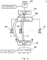
- Fig. 7 shows a network configuration example of the communication system according to the first example embodiment and an image of the flow of packets (frames).
- IP addresses of the same subnetwork are set for the management device 400 and the factory equipment 300.
- "192.16.0.1” is set for a wired LAN interface ETH4 of the management device 400
- "192.16.0.2” is set for a wired LAN interface ETH3 of the factory equipment 300.
- IP addresses of the same subnetwork as that of the management device 400 and the factory equipment 300 are set for the fixed transfer device 200 on the side of the management device 400 and for the mobile transfer device 100 on the side of the factory equipment 300.
- IP addresses of the same subnetwork as that of the management device 400 and the factory equipment 300 are set for the fixed transfer device 200 on the side of the management device 400 and for the mobile transfer device 100 on the side of the factory equipment 300.
- "192.168.101” is set for the packet transfer unit BR2 of the fixed transfer device 200
- "192.168.0.102” is set for the packet transfer unit BR1 of the mobile transfer device 100.
- IP addresses of a different subnetwork from that of the management device 400 and the factory equipment 300 are set for the fixed transfer device 200 and the mobile transfer device 100 on the wireless LAN side. Further, an IP address of a different subnetwork is set for each communication path to be made redundant. Specifically, in the fixed transfer device 200 and the mobile transfer device 100, subnetworks are different between a path through the access point AP1 and a path through the access point AP2. For example, "192.168.10.1” is set for the wired LAN interface ETH21 of the fixed transfer device 200, and “192.168.10.2” is set for the wireless LAN interface WLAN10 of the mobile transfer device 100. Further, “192.168.20.1” is set for the wired LAN interface ETH22 of the fixed transfer device 200, and “192.168.20.2” is set for the wireless LAN interface WLAN11 of the mobile transfer device 100.
- the factory equipment 300 When transmitting a packet from the factory equipment 300 to the management device 400, for example, the factory equipment 300 transmits the packet from "192.168.0.2" to "192.168.0.1".
- the mobile transfer device 100 receives a packet by the wired LAN interface ETH1, and the packet transfer unit BR1 transfers the received packet to "192.168.0.1".
- the encapsulation interface GRE1 encapsulates by GRE a frame containing the packet, and the redundancy unit CP1 copies the encapsulated frame.
- the two copied encapsulated frames are transmitted respectively from the wireless LAN interfaces WLAN10 and WLAN11 through the access point AP1 and the access point AP2. Specifically, the encapsulated frame is transmitted from "192.168.10.2" of the wireless LAN interface WLAN10 to "192.168.10.1” of the wired LAN interface ETH21 of the management device 400, and the encapsulated frame is transmitted from "192.168.20.2" of the wireless LAN interface WLAN11 to "192.168.20.1" of the wired LAN interface ETH22 of the management device 400.
- the fixed transfer device 200 receives the encapsulated frames by the wired LAN interfaces ETH21 and ETH22, and then the encapsulation interface GRE2 decapsulates the received encapsulated frames, and the redundancy unit CP2 discards a duplicate packet. Since the packet contained in the decapsulated frame is the packet addressed to "192.168.0.1" from "192.168.0.2" transmitted by the factory equipment 300, it is transmitted by the packet transfer unit BR2 from the wired LAN interface ETH20 to the management device 400.
- the management device 400 when transmitting a packet from the management device 400 to the factory equipment 300, the management device 400 transmits the packet from "192.168.0.1" to "192.168.0.2.
- the fixed transfer device 200 receives a packet by the wired LAN interface ETH20, and then the packet transfer unit BR2 transfers the received packet to "192.168.0.2". At this time, the encapsulation interface GRE2 encapsulates by GRE a frame containing the packet, and the redundancy unit CP2 copies the encapsulated frame.
- the two copied encapsulated frames are transmitted respectively from the wired LAN interfaces ETH21 and ETH22 through the access point AP1 and the access point AP2. Specifically, the encapsulated frame is transmitted from "192.168.10.1” of the wired LAN interface ETH21 to "192.168.10.2” of the wireless LAN interface WLAN10 of the mobile transfer device 100, and the encapsulated frame is transmitted from "192.168.20.1" of the wired LAN interface ETH22 to "192.168.20.2" of the wireless LAN interface WLAN11 of the mobile transfer device 100.
- the mobile transfer device 100 receives the encapsulated frames by the wireless LAN interfaces WLAN10 and WLAN11, and then the encapsulation interface GRE1 decapsulates the received encapsulated frames, and the redundancy unit CP1 discards a duplicate packet. Since the packet contained in the decapsulated frame is the packet addressed to "192.168.0.2" from "192.168.0.1" transmitted by the management device 400, it is transmitted by the packet transfer unit BR1 from the wired LAN interface ETH1 to the factory equipment 300.
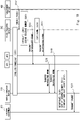
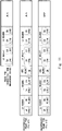
- Fig. 8 is a sequence chart of transmitting a packet from the factory equipment 300 to the management device 400, and Fig. 9 shows an example of frame formats in this case.
- the mobile transfer device 100 establishes tunneling between the fixed transfer device 200 and the mobile transfer device 100 in advance (S101).
- the mobile transfer device 100 establishes Layer 2 tunneling (encapsulates a Layer 2 frame) in accordance with the GRE protocol. This enables the mobile transfer device 100 to perform encapsulation communication between the encapsulation interface GRE1 and the fixed transfer device 200.
- the factory equipment 300 transmits a packet addressed to the management device 400 (S102).
- the frame FRM1 in Fig. 9 is an example of a frame that contains a packet transmitted from the factory equipment 300.
- the packet contained in FRM1 is a TCP/IP packet, for example.
- an application and a change in settings are not needed in the factory equipment 300 and the management device 400, and transmission and reception of a typical TCP/IP packet are possible.
- the frame FRM1 contains a Layer 2 header (MAC header), a Layer 3 header (IP header), and transmission data.
- the factory equipment 300 sets the MAC address of the wired LAN interface ETH3 of the factory equipment 300 to a source MAC address SA of the Layer 2 header of the frame FRM1, and sets the MAC address of the wired LAN interface ETH4 of the management device 400 (or the MAC address of the mobile transfer device 100) to a destination MAC address DA.
- the factory equipment 300 sets the IP address of the wired LAN interface ETH4 of the factory equipment 300 to the source IP address SA of the Layer 3 header of the frame FRM1, and sets the IP address of the wired LAN interface ETH4 of the management device 400 to the destination IP address DA.
- the mobile transfer device 100 receives the packet from the factory equipment 300, and encapsulates by GRE the frame containing the packet (S103), and assigns (includes) a sequence number to the encapsulated frame (S104).
- the frame FRM2 in Fig. 9 is an example of the encapsulated frame generated at this time. As shown in Fig. 9 , the mobile transfer device 100 generates the frame FRM2 by adding a Layer 2 header, a Layer 3 header, and a GRE header to the frame FRM1 received from the factory equipment 300, and assigns a sequence number to the GRE header.
- the mobile transfer device 100 Since the encapsulated frame FRM2 is a frame to be transmitted through the access point AP1, the mobile transfer device 100 sets the MAC address of the wireless LAN interface WLAN10 to the source MAC address SA of the Layer 2 header of the frame FRM2, and sets the MAC address of the wired LAN interface ETH21 of the fixed transfer device 200 to the destination MAC address DA.
- the IP address of the wireless LAN interface WLAN10 is set to the source IP address SA of the Layer 3 header of the frame FRM2, and the IP address of the wired LAN interface ETH21 of the fixed transfer device 200 is set to the destination IP address DA. Note that, if it is receivable by the wired LAN interface ETH21 of the fixed transfer device 200, the IP address of the wired LAN interface ETH22 may be set.
- the mobile transfer device 100 transmits the generated frame FRM2 to the access point AP1 (S105).
- the wireless LAN interface WLAN10 transmits the encapsulated frame FRM2 after converting it into a wireless LAN format. To be specific, it generates a wireless LAN frame where the BSSID of the access point AP1 is further added to the Layer 2 header of the frame FRM2.
- the mobile transfer device 100 copies the encapsulated frame (S106).
- the frame FRM3 in Fig. 9 is an example of the encapsulated frame generated at this time.
- the mobile transfer device 100 copies the frame FRM2 and generates the frame FRM3. Since the encapsulated frame FRM3 is a frame to be transmitted through the access point AP2, the mobile transfer device 100 sets the MAC address of the wireless LAN interface WLAN11 to the source MAC address SA of the Layer 2 header of the frame FRM3, and sets the MAC address of the wired LAN interface ETH22 of the fixed transfer device 200 to the destination MAC address DA. Communication through the access point AP2 is thereby reliably carried out, as in the case of the frame FRM2.
- the IP address of the wireless LAN interface WLAN11 is set to the source IP address SA of the Layer 3 header of the frame FRM3, and the IP address of the wired LAN interface ETH22 of the fixed transfer device 200 is set to the destination IP address DA. If it is receivable by the wired LAN interface ETH22 of the fixed transfer device 200, the IP address of the wired LAN interface ETH21 may be set as in the case of the frame FRM2.
- the mobile transfer device 100 transmits the generated frame FRM3 to the access point AP2 (S107).
- the wireless LAN interface WLAN11 transmits the encapsulated frame FRM3 after converts it into a wireless LAN format. To be specific, it generates a wireless LAN frame where the BSSID of the access point AP2 is further added to the Layer 2 header of the frame FRM3.
- the access point AP1 transfers, to the fixed transfer device 200, the frame (the wireless LAN frame of FRM2) received from the mobile transfer device 100 (S108).
- the access point AP1 transmits the received wireless LAN frame after converting it into the format of the frame FRM2 in Fig. 9 . To be specific, it removes the BSSID of the access point AP1 from the Layer 2 header of the wireless LAN frame and thereby generates the frame FRM2.
- the access point AP2 transfers, to the fixed transfer device 200, the frame (the wireless LAN frame of FRM3) received from the mobile transfer device 100 (S109).
- the access point AP2 transmits the received wireless LAN frame after converting it into the format of the frame FRM3 in Fig. 9 . To be specific, it removes the BSSID of the access point AP2 from the Layer 2 header of the wireless LAN frame and thereby generates the frame FRM3.
- the fixed transfer device 200 receives the encapsulated frames from the access points AP1 and AP2, and performs decapsulation (S110), sorting by sequence number (S111), and elimination of a duplicate packet (S112).
- S110 decapsulation
- S111 sorting by sequence number
- S112 elimination of a duplicate packet
- the fixed transfer device 200 receives the encapsulated frame FRM2 from the access point AP1
- it removes the Layer 2 header and the GRE header from the encapsulated frame FRM2
- thereby generates the frame FRM1 in Fig. 9 Likewise, when the fixed transfer device 200 receives the encapsulated frame FRM3 from the access point AP2, it removes the Layer 2 header and the GRE header from the encapsulated frame FRM3, and thereby generates the frame FRM1 in Fig. 9 .
- the received packets (frames) are sorted according to the order of the sequence numbers contained in the GRE headers, and if there is a packet with the same sequence number
- the fixed transfer device 200 transmits the packet to the management device 400 (S113). Since the packet contained in the decapsulated frame is addressed to the management device 400, the fixed transfer device 200 transmits this packet to the management device 400.
- Fig. 10 is a sequence chart of transmitting a packet from the management device 400 to the factory equipment 300, and Fig. 11 shows an example of frame formats in this case.
- the fixed transfer device 200 establishes tunneling between the mobile transfer device 100 and the fixed transfer device 200 (S201) in the same manner as shown in Fig. 8 .
- the management device 400 transmits a packet addressed to the factory equipment 300 (S202).
- the frame FRM4 in Fig. 11 is an example of a frame that contains a packet transmitted from the management device 400, and it has the same format as the frame FRM1 in Fig. 9 .
- the management device 400 sets the MAC address of the wired LAN interface ETH4 of the management device 400 to the source MAC address SA of the Layer 2 header of the frame FRM4, and sets the MAC address of the wired LAN interface ETH3 of the factory equipment 300 to the destination MAC address DA.
- the management device 400 sets the IP address of the wired LAN interface ETH4 of the management device 400 to the source IP address SA of the Layer 3 header of the frame FRM4, and sets the IP address of the wired LAN interface ETH3 of the factory equipment 300 to the destination IP address DA.
- the fixed transfer device 200 receives the packet from the management device 400, and encapsulates the frame by GRE (S203), and assigns (includes) a sequence number to the encapsulated frame (S204) in the same manner as shown in Fig. 8 .
- the frame FRM5 in Fig. 11 is an example of the encapsulated frame generated at this time, and it has the same format as the frame FRM2 in Fig. 9 .
- the fixed transfer device 200 sets the MAC address of the wired LAN interface ETH21 of the fixed transfer device 200 to the source MAC address SA of the Layer 2 header of the frame FRM5, and sets the MAC address of the wireless LAN interface WLAN10 to the destination MAC address DA.
- the fixed transfer device 200 sets the IP address of the wired LAN interface ETH21 of the fixed transfer device 200 to the source IP address SA of the Layer 3 header of the frame FRM5, and sets the IP address of the wireless LAN interface WLAN10 to the destination IP address DA.
- the fixed transfer device 200 transmits the generated frame FRM5 to the access point AP1 (S205), and copies the encapsulated frame (S206).
- the frame FRM6 in Fig. 11 is an example of the encapsulated frame generated at this time, and it has the same format as the frame FRM3 in Fig. 9 .
- the fixed transfer device 200 sets the MAC address of the wired LAN interface ETH22 of the fixed transfer device 200 to the source MAC address SA of the Layer 2 header of the frame FRM6, and sets the MAC address of the wireless LAN interface WLAN11 to the destination MAC address DA.
- the fixed transfer device 200 sets the IP address of the wired LAN interface ETH22 of the fixed transfer device 200 to the source IP address SA of the Layer 3 header of the frame FRM6, and sets the IP address of the wireless LAN interface WLAN11 to the destination IP address DA. Further, the fixed transfer device 200 transmits the generated frame FRM6 to the access point AP2 (S207).
- the access point AP1 transfers, to the mobile transfer device 100, the frame (FRM5) received from the fixed transfer device 200 (S208).
- the access point AP1 transmits the encapsulated frame FRM5 after converting it into a wireless LAN format. To be specific, it generates a wireless LAN frame where the BSSID of the access point AP1 is further added to the Layer 2 header of the frame FRM5.
- the access point AP2 transfers, to the mobile transfer device 100, the frame (FRM6) received from the fixed transfer device 200 (S209).
- the access point AP2 transmits the encapsulated frame FRM6 after converting it into a wireless LAN format. To be specific, it generates a wireless LAN frame where the BSSID of the access point AP2 is further added to the Layer 2 header of the frame FRM6.
- the mobile transfer device 100 receives the wireless LAN frames from the access points AP1 and AP2, and performs decapsulation (S210), sorting by sequence number (S211), and elimination of a duplicate packet (S212).
- S210 decapsulation
- S211 sorting by sequence number
- S212 elimination of a duplicate packet
- the mobile transfer device 100 receives the wireless LAN frame from the access point AP1, it converts this frame into the format of the frame FRM5 in Fig. 11 . To be specific, it removes the BSSID of the access point AP1 from the Layer 2 header of the wireless LAN frame and thereby generates the frame FRM5. Further, it eliminates the Layer 2 header and the GRE header from the encapsulated frame FRM5, and thereby generates the frame FRM4 in Fig. 11 .
- the mobile transfer device 100 receives the wireless LAN frame from the access point AP2, it removes the BSSID from the Layer 2 header of the wireless LAN frame and thereby generates the frame FRM6, and further eliminates the Layer 2 header and the GRE header and thereby generates the frame FRM4 in Fig. 11 .
- the mobile transfer device 100 sorts the packets according to the sequence numbers contained in the GRE headers, and discards a duplicate packet in the same manner as shown in Fig. 9 .
- the mobile transfer device 100 transmits the packet to the factory equipment 300 (S213). Since the packet contained in the decapsulated frame is addressed to the factory equipment 300, the mobile transfer device 100 transmits this packet to the factory equipment 300.
- a plurality of wireless LAN paths are prepared to achieve redundancy in a communication system of a factory or the like, and the transmitting side transmits frames to both of the paths, and the receiving side processes the frame that arrives earlier. Further, the receiving side performs sequence control. This enhances the reliability of wireless LAN communication where communication of a frame is unstable.
- encapsulation communication such as GRE is used to achieve wireless communication without need of an application or a change in settings of existing equipment. Further, this allows use of typical TCP/IP communication or UDP/IP communication between existing equipment, and avoids the Duplicate ACK problem or the duplicate reception problem by sequence control or duplicate packet elimination.
- the MAC address of the wireless LAN interface is set to the source MAC address, so that the frame is not discarded at the access point and communication is done reliably through the access point.
- information of the whole Layer 2 frame containing original Layer 2 to Layer 4 headers is left, and further two copies of this information are prepared, and Layer 2 headers are set to enable communication of the two copied frames to different wireless LAN access points, and then the frames are transmitted by Layer 3 routing.
- redundancy communication (generation of a plurality of frames) is always performed using a plurality of paths in the above-described example embodiment, determination whether to perform redundancy communication may be made.
- redundancy communication may be performed according to the priority of a frame to be transmitted.
- redundancy transmission may be performed when the priority of a frame is higher than a predetermined criterion by referring to information (input interface information, MAC header information, IP header information, and TCP header) about Layers 1 to 4 of packets. This may be achieved by setting a mark according to the priority to the frame at specified timing.
- redundancy communication may be performed according to the wireless communication quality of a wireless LAN.
- the radio field intensity or communication errors may be monitored for each wireless LAN interface, and redundancy transmission may be performed when the wireless communication quality of any wireless LAN interface is lower than a predetermined criterion.
- Each element in the above-described example embodiment may be formed by hardware or software or both of them, and may be formed by one hardware or software or a plurality of hardware or software.
- the function (processing) of each device may be implemented by a computer including a CPU, a memory and the like.
- a control program for performing a communication method according to the example embodiment may be stored in a storage device, and each function may be implemented by executing the program stored in the storage device on the CPU.
- Non-transitory computer readable media include any type of tangible storage medium.
- Examples of the non-transitory computer readable media include magnetic storage media (such as flexible disks, magnetic tapes, hard disk drives, etc.), and optical magnetic storage media (e.g. magneto-optical disks), CD-ROM (Read Only Memory), CD-R, and CD-R/W, semiconductor memories (e.g., mask ROM, PROM (Programmable ROM), EPROM (Erasable PROM), flash ROM, and RAM (Random Access Memory)).
- the program may be provided to a computer using any type of transitory computer readable medium. Examples of transitory computer readable media include electric signals, optical signals, and electromagnetic waves.
- the transitory computer readable medium can provide the program to a computer via a wired communication line such as an electric wire or an optical fiber, or a wireless communication line.
- a communication device comprising:
- the redundancy means sets, to a destination MAC address of the first encapsulated frame, a MAC address of a wired LAN interface of the communication device at other side to which the first wireless LAN access point is connected, and sets, to a destination MAC address of the second encapsulated frame, a MAC address of a wired LAN interface of the communication device at other side to which the second wireless LAN access point is connected.
- the redundancy means sets, to a destination IP address of the first encapsulated frame, an IP address of a wired LAN interface of the communication device at other side to which the first or second wireless LAN access point is connected, and sets, to a destination IP address of the second encapsulated frame, an IP address of a wired LAN interface of the communication device at other side to which the first or second wireless LAN access point is connected.
- the communication device according to any one of Supplementary Notes 1 to 3, wherein the encapsulation means assigns a sequence number to an encapsulation header when it is encapsulating the transmission frame.
- the communication device according to any one of Supplementary Notes 1 to 4, wherein the redundancy means generates the first and second encapsulated frames according to a priority of the transmission frame.
- the communication device according to any one of Supplementary Notes 1 to 5, wherein the redundancy means generates the first and second encapsulated frames according to quality of wireless communication with the first wireless LAN access point or quality of wireless communication with the second wireless LAN access point.
- the communication device according to any one of Supplementary Notes 1 to 6, wherein a wireless channel to be used or wireless transmission timing of the first wireless LAN interface differs from that of the second wireless LAN interface.
- a communication system comprising:
- the redundancy means sets, to a destination MAC address of the first encapsulated frame, a MAC address of a wired LAN interface of the communication device at other side to which the first wireless LAN access point is connected, and sets, to a destination MAC address of the second encapsulated frame, a MAC address of a wired LAN interface of the communication device at other side to which the second wireless LAN access point is connected.
- a communication method comprising:
- a MAC address of a wired LAN interface of the communication device at other side to which the first wireless LAN access point is connected is set to a destination MAC address of the first encapsulated frame
- a MAC address of a wired LAN interface of the communication device at other side to which the second wireless LAN access point is connected is set to a destination MAC address of the second encapsulated frame.
- a communication program causing a computer to execute a process comprising:
- a MAC address of a wired LAN interface of the communication device at other side to which the first wireless LAN access point is connected is set to a destination MAC address of the first encapsulated frame
- a MAC address of a wired LAN interface of the communication device at other side to which the second wireless LAN access point is connected is set to a destination MAC address of the second encapsulated frame.
- a communication device comprising:
Landscapes
- Engineering & Computer Science (AREA)
- Computer Networks & Wireless Communication (AREA)
- Signal Processing (AREA)
- Mobile Radio Communication Systems (AREA)
- Data Exchanges In Wide-Area Networks (AREA)
Abstract
Description
- The present invention relates to a communication device, a communication system, a communication method, and a non-transitory computer readable medium storing a communication program.
- Wireless communication such as a wireless LAN (Local Area Network) is widespread today and used in various systems at home, office, factory and the like. Use of wireless communication allows freely moving a communication device without limitation of wiring or the like. While this enhances convenience, it is desired to ensure the quality of communication including wireless communication.
-
Patent Literatures Patent Literature 1, when transmitting a packet in a packet transfer device that performs communication through redundant paths in a wide area network or the like, the device makes a copy of the packet and assigns a sequence number indicating the sequential order to the packet, or uses GRE (Generic Routing Encapsulation) technology. According toPatent Literature 2, when a mobile IP system receives an encapsulated packet, it decapsulates the packet to check the sequence number and the arrival time. -
- PTL1:
Japanese Unexamined Patent Application Publication No. 2007-209040 - PTL2:
Japanese Unexamined Patent Application Publication No. 2008-160495 - The related art such as
Patent Literatures - To solve the above problem, an object of the present disclosure is to provide a communication device, a communication system, a communication method, and a non-transitory computer readable medium storing a communication program capable of enhancing the reliability of communication including wireless communication.
- A communication device according to the present disclosure includes a first wireless LAN interface configured to wirelessly communicate with a first wireless LAN access point; a second wireless LAN interface configured to wirelessly communicate with a second wireless LAN access point; an encapsulation means for encapsulating, in accordance with a specified encapsulation protocol, a transmission frame to be transmitted to a communication device at other side via
Layer 2 tunneling; and a redundancy means for generating a first encapsulated frame where a MAC address of the first wireless LAN interface is set to a source MAC address and a second encapsulated frame where a MAC address of the second wireless LAN interface is set to a source MAC address by using the encapsulated transmission frame, wherein the first wireless LAN interface wirelessly transmits the generated first encapsulated frame to the first wireless LAN access point, and the second wireless LAN interface wirelessly transmits the generated second encapsulated frame to the second wireless LAN access point. - A communication system according to the present disclosure includes first and second communication devices, and first and second wireless LAN access points connected to the second communication device, wherein the first communication device includes a first wireless LAN interface configured to wirelessly communicate with the first wireless LAN access point; a second wireless LAN interface configured to wirelessly communicate with the second wireless LAN access point; an encapsulation means for encapsulating, in accordance with a specified encapsulation protocol, a transmission frame to be transmitted to the second communication device via
Layer 2 tunneling; and a redundancy means for generating a first encapsulated frame where a MAC address of the first wireless LAN interface is set to a source MAC address and a second encapsulated frame where a MAC address of the second wireless LAN interface is set to a source MAC address by using the encapsulated transmission frame, the first wireless LAN interface wirelessly transmits the generated first encapsulated frame to the first wireless LAN access point, and the second wireless LAN interface wirelessly transmits the generated second encapsulated frame to the second wireless LAN access point. - A communication method according to the present disclosure includes encapsulating, in accordance with a specified encapsulation protocol, a transmission frame to be transmitted to a communication device at other side via
Layer 2 tunneling; generating a first encapsulated frame where a MAC address of a first wireless LAN interface is set to a source MAC address and a second encapsulated frame where a MAC address of a second wireless LAN interface is set to a source MAC address by using the encapsulated transmission frame, the first wireless LAN interface being configured to wirelessly communicate with a first wireless LAN access point, and the second wireless LAN interface being configured to wirelessly communicate with a second wireless LAN access point; wirelessly transmitting the generated first encapsulated frame from the first wireless LAN interface to the first wireless LAN access point; and wirelessly transmitting the generated second encapsulated frame from the second wireless LAN interface to the second wireless LAN access point. - A non-transitory computer readable medium storing a communication program according to the present disclosure is a non-transitory computer readable medium storing a communication program causing a computer to execute a process including encapsulating, in accordance with a specified encapsulation protocol, a transmission frame to be transmitted to a communication device at other side via
Layer 2 tunneling; generating a first encapsulated frame where a MAC address of a first wireless LAN interface is set to a source MAC address and a second encapsulated frame where a MAC address of a second wireless LAN interface is set to a source MAC address by using the encapsulated transmission frame, the first wireless LAN interface being configured to wirelessly communicate with a first wireless LAN access point, and the second wireless LAN interface being configured to wirelessly communicate with a second wireless LAN access point; wirelessly transmitting the generated first encapsulated frame from the first wireless LAN interface to the first wireless LAN access point; and wirelessly transmitting the generated second encapsulated frame from the second wireless LAN interface to the second wireless LAN access point. - According to the present disclosure, there are provided a communication device, a communication system, a communication method, and a communication program capable of enhancing the reliability of communication including wireless communication.
-
-
Fig. 1 is a block diagram showing an overview of a communication system according to an example embodiment. -
Fig. 2 is a block diagram showing an overview of a first communication device according to an example embodiment. -
Fig. 3 is a block diagram showing an overview of a second communication device according to an example embodiment. -
Fig. 4 is a block diagram showing a configuration example of a communication system according to a first example embodiment. -
Fig. 5 is a block diagram showing a configuration example of a mobile transfer device according to the first example embodiment. -
Fig. 6 is a block diagram showing a configuration example of a fixed transfer device according to the first example embodiment. -
Fig. 7 is a block diagram showing a network configuration example of a communication system according to the first example embodiment. -
Fig. 8 is a sequence chart showing an operation example of the communication system according to the first example embodiment. -
Fig. 9 is a view showing a format example of a frame used in the communication system according to the first example embodiment. -
Fig. 10 is a sequence chart showing an operation example of the communication system according to the first example embodiment. -
Fig. 11 is a view showing a format example of a frame used in the communication system according to the first example embodiment. - Example embodiments will be described hereinafter with reference to the drawings. In the figures, the identical reference symbols denote identical structural elements and the redundant explanation thereof is omitted.
-
Fig. 1 shows an overall configuration of acommunication system 1 according to an example embodiment, andFigs. 2 and3 show overall configurations of two communication devices that constitute thecommunication system 1. - As shown in
Fig. 1 , thecommunication system 1 according to the example embodiment includes a communication device (first communication device) 10, a communication device (second communication device) 20, an access point (first wireless LAN access point) 31, and an access point (second wireless LAN access point) 32. Theaccess points communication device 20, and wirelessly communicate with thecommunication device 10. Thecommunication devices access point 31 and a path R2 through theaccess point 32. - As shown in
Fig. 2 , thecommunication device 10 includeswireless LAN interfaces encapsulation unit 13, and aredundancy unit 14. The wireless LAN interface (first wireless LAN interface) 11 wirelessly communicates with theaccess point 31. The wireless LAN interface (second wireless LAN interface) 12 wirelessly communicates with theaccess point 32. - The
encapsulation unit 13 encapsulates, in accordance with a specified encapsulation protocol, a transmission frame to be transmitted to thecommunication device 20 viaLayer 2 tunneling. Theredundancy unit 14 generates a first encapsulated frame where the MAC address of thewireless LAN interface 11 is set to a sender MAC address and a second encapsulated frame where the MAC address of thewireless LAN interface 12 is set to the source MAC address by using the encapsulated transmission frame. Further, thewireless LAN interface 11 wirelessly transmits the generated first encapsulated frame to theaccess point 31 and thewireless LAN interface 12 wirelessly transmits the generated second encapsulated frame to theaccess point 32. The transmission frame is thereby transmitted through two paths: the path R1 and the path R2. - As shown in
Fig. 3 , thecommunication device 20 includes areceiving unit 21, aredundancy unit 22, and adecapsulation unit 23. Thereceiving unit 21 receives the first encapsulated frame from thecommunication device 10 through theaccess point 31 that is connected by wire, and receives the second encapsulated frame from thecommunication device 10 through theaccess point 32 that is connected by wire. Theredundancy unit 22 selects one of the first encapsulated frame and the second encapsulated frame received by thereceiving unit 21. For example, duplication of a packet is eliminated using a sequence number. Thedecapsulation unit 23 decapsulates the encapsulated frame selected by theredundancy unit 22. - As described above, in this example embodiment, when performing communication via
Layer 2 tunneling between a communication device that performs wireless LAN communication and a communication device that is connected to access points, a frame is transmitted and received through redundant paths via two access points. Further, the transmitting side sets the MAC address of the wireless LAN interface that wirelessly communicates with the access point of each path to the source MAC address for the encapsulated frame, and transmits the set frame. This allows wireless communication through the access point to be done reliably and thereby enhances the reliability of communication including wireless communication. - A first example embodiment is described hereinafter with reference to the drawings.
Fig. 4 shows a configuration example of acommunication system 2 according to this example embodiment. - The
communication system 2 is a system that enables communication betweenfactory equipment 300 and amanagement device 400. For example, thecommunication system 2 constructs a factory network in a factory having manufacturing facilities or the like. In a factory, equipment are often moved due to a change in manufacturing line or the like. If equipment are connected through a wired network (a wired LAN such as Ethernet (registered trademark), for example), it requires time and manpower to change wiring or the like when moving the equipment, and it is therefore desirable to reduce such time and manpower required. Further, mobile equipment such as an AGV (Automated Guided Vehicle) is placed in a factory, and a wired network cannot sufficiently support communication of such mobile equipment. - In view of the above circumstances, a part of the communication path between the
factory equipment 300 and themanagement device 400 is provided by a wireless network using a wireless LAN in consideration of moving factory equipment. On the other hand, use of a wireless LAN may cause unstable communication quality compared with use of a wired LAN. Therefore, this example embodiment aims at enhancing the reliability of wireless LAN communication between thefactory equipment 300 and themanagement device 400. - As shown in
Fig. 4 , in addition to thefactory equipment 300 and themanagement device 400, thecommunication system 2 according to this example embodiment includes a mobile transfer device (first communication device) 100, a fixed transfer device (second communication device) 200, a plurality of access points AP, and aLayer 2 switching hub HUB between thefactory equipment 300 and themanagement device 400. - The plurality of access points AP are placed at specified intervals in the factory, and transfer data in bridge mode, for example. Different BSSID (Basic Service Set Identifiers) are set respectively to the plurality of access points AP (including AP1 and AP2), and wireless communication with a desired access point is enabled by setting the BSSID of the access point to a wireless LAN frame. Further, each access point AP is capable of wireless communication using an arbitrary channel. For example, channels that do not interfere with each other, such as channels of 2.4GHz and 5GHz bands, may be used.
- For example, the
factory equipment 300 is an AGV (Automated Guided Vehicle) that automatically runs in a factory or a movable industrial robot, and themanagement device 400 is a management server that manages the driving or the like of thefactory equipment 300. Thefactory equipment 300 transmits its location information or the like to themanagement device 400, and themanagement device 400 transmits direction information of movement or the like to thefactory equipment 300. Note that thefactory equipment 300 and themanagement device 400 may be other arbitrary devices. - The
mobile transfer device 100 is a transfer device that transfers packets transmitted to and received by thefactory equipment 300. Themobile transfer device 100 performs wireless communication with the plurality of access points AP, and performs encapsulation communication with the fixedtransfer device 200 through the plurality of access points AP by using a plurality of paths (e.g., T1 and T2). Themobile transfer device 100 is placed to be movable together with thefactory equipment 300, and is connected to thefactory equipment 300 by wired LAN. Themobile transfer device 100 and thefactory equipment 300 move in a factory and communicate with the fixed transfer device and themanagement device 400 through nearby (e.g., two) access points AP. Although themobile transfer device 100 and thefactory equipment 300 are separate devices in this example, themobile transfer device 100 and thefactory equipment 300 may be one device. Specifically, themobile transfer device 100 may be built in thefactory equipment 300. - The fixed
transfer device 200 is a transfer device that transfers packets transmitted to and received by themanagement device 400. The fixedtransfer device 200 is connected by wired LAN to the plurality of access points AP through theLayer 2 switching hub HUB. The fixedtransfer device 200 performs wired communication with the plurality of access points AP, and performs encapsulation communication with themobile transfer device 100 through the plurality of access points AP. Although the fixedtransfer device 200 and themanagement device 400 are separate devices in this example, the fixedtransfer device 200 and themanagement device 400 may be one device. Specifically, the fixedtransfer device 200 may be built in themanagement device 400. - IP addresses of the same subnetwork are set for the
management device 400 and thefactory equipment 300. For example, "192.16.0.1" is set for themanagement device 400, and "192.16.0.2" is set for thefactory equipment 300. This example embodiment enables wireless communication between themanagement device 400 and thefactory equipment 300 without changing settings such as the IP addresses (subnetwork) of themanagement device 400 and thefactory equipment 300 or applications. Specifically, by providing the configuration of the fixedtransfer device 200 to themobile transfer device 100 between themanagement device 400 and thefactory equipment 300, communication by wireless LAN is possible without affecting themanagement device 400 and thefactory equipment 300. To achieve this, in this example embodiment, GRE encapsulation communication (Layer 2 tunneling communication) is performed between themobile transfer device 100 and the fixedtransfer device 200, and further redundancy of the communication path is achieved with the path T1 and the path T2. Note that redundant paths may be any two or more paths. Further, another encapsulation protocol, not limited to GRE, may be used. -
Fig. 5 shows a configuration example of themobile transfer device 100 according to this example embodiment. As shown inFig. 5 , themobile transfer device 100 includes a wired LAN interface ETH1, wireless LAN interfaces WLAN10 and WLAN11, an encapsulation interface GRE1, and a packet transfer unit BR1. Note that the number of wireless LAN interfaces is not limited to two. A plurality of wireless LAN interfaces may be included according to the number of redundant paths. - The wired LAN interface ETH1 is a wired communication unit that performs Ethernet communication. The wired LAN interface ETH1 is connected by wire to the
factory equipment 300 and transmits and receives packets to and from thefactory equipment 300. - The wireless LAN interfaces WLAN10 and WLAN11 are wireless communication units that perform wireless LAN communication, and wirelessly communicate with any of the access points AP. The wireless LAN interfaces WLAN10 and WLAN11 communicate with a desired access point AP by setting the BSSID of the access point AP to a wireless LAN frame. Note that, by associating (registering) the MAC address of a wireless LAN interface with an access point AP in advance, wireless communication can be carried out between the wireless LAN interface and the access point AP without discarding the wireless LAN frame.
- The wireless LAN interfaces WLAN10 and WLAN11 also serve as redundant transmission units that transmit the same frame to redundant paths. In the wireless LAN interfaces WLAN10 and WLAN11, it is preferred that radio signals do not interfere with each other in the transmission of redundant frames (encapsulated frames). To avoid interference, channels that do not interfere with each other may be used. For example, the wireless LAN interface WLAN10 may wirelessly communicate with the access point AP1 by using the channel of 2.4GHz band, and the wireless LAN interface WLAN11 may wirelessly communicate with the access point AP2 by using the channel of 5GHz band, so that redundant frames are simultaneously transmitted.
- Further, when using channels that interfere with each other, it is desirable to control transmission in such a way that the timing of transmission is different from each other. For example, ON/OFF of wireless transmission may be controlled in such a way that the wireless transmission period does not overlap between the wireless LAN interfaces WLAN10 and WLAN11.
- The encapsulation interface GRE1 is an encapsulation communication unit (virtual interface) that performs GRE encapsulation communication. The encapsulation interface GRE1 performs encapsulation communication by establishing a GRE tunnel between the
fixed transfer device 200 and the encapsulation interface GRE1. The encapsulation interface GRE1 encapsulates a frame containing a packet received from thefactory equipment 300 and further decapsulates an encapsulated frame received from the access point AP. - The packet transfer unit BR1 is a transfer unit that transfers packets transmitted and received in each interface of the
mobile transfer device 100. The packet transfer unit BR1 has a routing table or a MAC address table. The packet transfer unit BR1 refers to the routing table or the like, and transfers the packet to the interface corresponding to the destination address (e.g., IP address) of the packet (or frame). Further, the packet transfer unit BR1 includes a redundancy unit CP1 that transmits and receives the frame to and from the redundant paths (e.g., the path T1 and the path T2). The redundancy unit CP1 assigns a sequence number or copies the frame when transferring the packet received from thefactory equipment 300 through the redundant paths. Further, when transferring frames received from the plurality of access points AP through the redundant paths to thefactory equipment 300, the redundancy unit CP1 may sort the packets in the order of sequence numbers and discard a duplicate packet on the basis of the sequence number. Specifically, in this example embodiment, the same IP packets are transmitted through two paths, and one of those packets received earlier is processed. -
Fig. 6 shows a configuration example of the fixedtransfer device 200 according to this example embodiment. As shown inFig. 6 , the fixedtransfer device 200 includes wired LAN interfaces ETH20, ETH21 and ETH22, an encapsulation interface GRE2, and a packet transfer unit BR2. Note that a plurality of wired LAN interfaces may be included according to the number of redundant paths. - The wired LAN interfaces ETH20, ETH21 and ETH22 are wired communication units that perform Ethernet communication. The wired LAN interface ETH20 is connected by wire to the
management device 400 and transmits and receives packets to and from themanagement device 400. - The wired LAN interfaces ETH21 and ETH22 are connected by wire to the
Layer 2 switching hub HUB. For example, the wired LAN interface ETH21 transmits and receives frames to and from themobile transfer device 100 through theLayer 2 switching hub HUB and the access point AP1. Further, the wired LAN interface ETH22 transmits and receives frames to and from themobile transfer device 100 through theLayer 2 switching hub HUB and the access point AP2. Although different IP addresses are set to the wired LAN interfaces ETH21 and ETH22, IP addresses may be shared so that any of the IP addresses can be received by an arbitrary interface. - The encapsulation interface GRE2 is an encapsulation communication unit (virtual interface) that performs GRE encapsulation communication. The encapsulation interface GRE2 performs encapsulation communication by establishing a GRE tunnel between the
mobile transfer device 100 and the encapsulation interface GRE2. The encapsulation interface GRE2 encapsulates a frame containing a packet received from themanagement device 400 and further decapsulates an encapsulated frame received from the access point AP. - The packet transfer unit BR2 is a transfer unit that transfers packets transmitted and received in each interface of the fixed
transfer device 200. The packet transfer unit BR2 has the same function as the packet transfer unit BR1 of themobile transfer device 100, and includes a redundancy unit CP2. The packet transfer unit BR2 refers to the routing table or the like, and transfers the packet to the interface corresponding to the destination address of the packet (or frame). The redundancy unit CP2 assigns a sequence number or copies the frame when transferring the packet received from themanagement device 400 through the redundant paths. Further, when transferring frames received from the plurality of access points AP through the redundant paths to themanagement device 400, the redundancy unit CP2 may sort the packets in the order of sequence numbers and discard a duplicate packet on the basis of the sequence number. -
Fig. 7 shows a network configuration example of the communication system according to the first example embodiment and an image of the flow of packets (frames). As illustrated inFig. 4 , IP addresses of the same subnetwork are set for themanagement device 400 and thefactory equipment 300. In this example, "192.16.0.1" is set for a wired LAN interface ETH4 of themanagement device 400, and "192.16.0.2" is set for a wired LAN interface ETH3 of thefactory equipment 300. - Further, IP addresses of the same subnetwork as that of the
management device 400 and thefactory equipment 300 are set for the fixedtransfer device 200 on the side of themanagement device 400 and for themobile transfer device 100 on the side of thefactory equipment 300. For example, "192.168.101" is set for the packet transfer unit BR2 of the fixedtransfer device 200, and "192.168.0.102" is set for the packet transfer unit BR1 of themobile transfer device 100. - On the other hand, IP addresses of a different subnetwork from that of the
management device 400 and thefactory equipment 300 are set for the fixedtransfer device 200 and themobile transfer device 100 on the wireless LAN side. Further, an IP address of a different subnetwork is set for each communication path to be made redundant. Specifically, in the fixedtransfer device 200 and themobile transfer device 100, subnetworks are different between a path through the access point AP1 and a path through the access point AP2. For example, "192.168.10.1" is set for the wired LAN interface ETH21 of the fixedtransfer device 200, and "192.168.10.2" is set for the wireless LAN interface WLAN10 of themobile transfer device 100. Further, "192.168.20.1" is set for the wired LAN interface ETH22 of the fixedtransfer device 200, and "192.168.20.2" is set for the wireless LAN interface WLAN11 of themobile transfer device 100. - When transmitting a packet from the
factory equipment 300 to themanagement device 400, for example, thefactory equipment 300 transmits the packet from "192.168.0.2" to "192.168.0.1". - The
mobile transfer device 100 receives a packet by the wired LAN interface ETH1, and the packet transfer unit BR1 transfers the received packet to "192.168.0.1". At this time, the encapsulation interface GRE1 encapsulates by GRE a frame containing the packet, and the redundancy unit CP1 copies the encapsulated frame. - The two copied encapsulated frames are transmitted respectively from the wireless LAN interfaces WLAN10 and WLAN11 through the access point AP1 and the access point AP2. Specifically, the encapsulated frame is transmitted from "192.168.10.2" of the wireless LAN interface WLAN10 to "192.168.10.1" of the wired LAN interface ETH21 of the
management device 400, and the encapsulated frame is transmitted from "192.168.20.2" of the wireless LAN interface WLAN11 to "192.168.20.1" of the wired LAN interface ETH22 of themanagement device 400. - The fixed
transfer device 200 receives the encapsulated frames by the wired LAN interfaces ETH21 and ETH22, and then the encapsulation interface GRE2 decapsulates the received encapsulated frames, and the redundancy unit CP2 discards a duplicate packet. Since the packet contained in the decapsulated frame is the packet addressed to "192.168.0.1" from "192.168.0.2" transmitted by thefactory equipment 300, it is transmitted by the packet transfer unit BR2 from the wired LAN interface ETH20 to themanagement device 400. - On the other hand, when transmitting a packet from the
management device 400 to thefactory equipment 300, themanagement device 400 transmits the packet from "192.168.0.1" to "192.168.0.2. - The fixed
transfer device 200 receives a packet by the wired LAN interface ETH20, and then the packet transfer unit BR2 transfers the received packet to "192.168.0.2". At this time, the encapsulation interface GRE2 encapsulates by GRE a frame containing the packet, and the redundancy unit CP2 copies the encapsulated frame. - The two copied encapsulated frames are transmitted respectively from the wired LAN interfaces ETH21 and ETH22 through the access point AP1 and the access point AP2. Specifically, the encapsulated frame is transmitted from "192.168.10.1" of the wired LAN interface ETH21 to "192.168.10.2" of the wireless LAN interface WLAN10 of the
mobile transfer device 100, and the encapsulated frame is transmitted from "192.168.20.1" of the wired LAN interface ETH22 to "192.168.20.2" of the wireless LAN interface WLAN11 of themobile transfer device 100. - The
mobile transfer device 100 receives the encapsulated frames by the wireless LAN interfaces WLAN10 and WLAN11, and then the encapsulation interface GRE1 decapsulates the received encapsulated frames, and the redundancy unit CP1 discards a duplicate packet. Since the packet contained in the decapsulated frame is the packet addressed to "192.168.0.2" from "192.168.0.1" transmitted by themanagement device 400, it is transmitted by the packet transfer unit BR1 from the wired LAN interface ETH1 to thefactory equipment 300. -
Fig. 8 is a sequence chart of transmitting a packet from thefactory equipment 300 to themanagement device 400, andFig. 9 shows an example of frame formats in this case. - As shown in
Fig. 8 , themobile transfer device 100 establishes tunneling between thefixed transfer device 200 and themobile transfer device 100 in advance (S101). In this example, themobile transfer device 100 establishesLayer 2 tunneling (encapsulates aLayer 2 frame) in accordance with the GRE protocol. This enables themobile transfer device 100 to perform encapsulation communication between the encapsulation interface GRE1 and the fixedtransfer device 200. - Next, the
factory equipment 300 transmits a packet addressed to the management device 400 (S102). The frame FRM1 inFig. 9 is an example of a frame that contains a packet transmitted from thefactory equipment 300. The packet contained in FRM1 is a TCP/IP packet, for example. In this example embodiment, an application and a change in settings are not needed in thefactory equipment 300 and themanagement device 400, and transmission and reception of a typical TCP/IP packet are possible. - As shown in
Fig. 9 , the frame FRM1 contains aLayer 2 header (MAC header), aLayer 3 header (IP header), and transmission data. Thefactory equipment 300 sets the MAC address of the wired LAN interface ETH3 of thefactory equipment 300 to a source MAC address SA of theLayer 2 header of the frame FRM1, and sets the MAC address of the wired LAN interface ETH4 of the management device 400 (or the MAC address of the mobile transfer device 100) to a destination MAC address DA. Further, thefactory equipment 300 sets the IP address of the wired LAN interface ETH4 of thefactory equipment 300 to the source IP address SA of theLayer 3 header of the frame FRM1, and sets the IP address of the wired LAN interface ETH4 of themanagement device 400 to the destination IP address DA. - Then, the
mobile transfer device 100 receives the packet from thefactory equipment 300, and encapsulates by GRE the frame containing the packet (S103), and assigns (includes) a sequence number to the encapsulated frame (S104). The frame FRM2 inFig. 9 is an example of the encapsulated frame generated at this time. As shown inFig. 9 , themobile transfer device 100 generates the frame FRM2 by adding aLayer 2 header, aLayer 3 header, and a GRE header to the frame FRM1 received from thefactory equipment 300, and assigns a sequence number to the GRE header. Since the encapsulated frame FRM2 is a frame to be transmitted through the access point AP1, themobile transfer device 100 sets the MAC address of the wireless LAN interface WLAN10 to the source MAC address SA of theLayer 2 header of the frame FRM2, and sets the MAC address of the wired LAN interface ETH21 of the fixedtransfer device 200 to the destination MAC address DA. - Use of a MAC address that is not associated with the access point AP1 may cause the frame to be discarded at the access point AP1. Thus, by setting the MAC address of the wireless LAN interface WLAN10 that is already associated with the access point AP1, communication through the access point AP1 is reliably carried out.
- Further, the IP address of the wireless LAN interface WLAN10 is set to the source IP address SA of the
Layer 3 header of the frame FRM2, and the IP address of the wired LAN interface ETH21 of the fixedtransfer device 200 is set to the destination IP address DA. Note that, if it is receivable by the wired LAN interface ETH21 of the fixedtransfer device 200, the IP address of the wired LAN interface ETH22 may be set. - Then, the
mobile transfer device 100 transmits the generated frame FRM2 to the access point AP1 (S105). At this time, the wireless LAN interface WLAN10 transmits the encapsulated frame FRM2 after converting it into a wireless LAN format. To be specific, it generates a wireless LAN frame where the BSSID of the access point AP1 is further added to theLayer 2 header of the frame FRM2. - After that, the
mobile transfer device 100 copies the encapsulated frame (S106). The frame FRM3 inFig. 9 is an example of the encapsulated frame generated at this time. As shown inFig. 9 , themobile transfer device 100 copies the frame FRM2 and generates the frame FRM3. Since the encapsulated frame FRM3 is a frame to be transmitted through the access point AP2, themobile transfer device 100 sets the MAC address of the wireless LAN interface WLAN11 to the source MAC address SA of theLayer 2 header of the frame FRM3, and sets the MAC address of the wired LAN interface ETH22 of the fixedtransfer device 200 to the destination MAC address DA. Communication through the access point AP2 is thereby reliably carried out, as in the case of the frame FRM2. - Further, the IP address of the wireless LAN interface WLAN11 is set to the source IP address SA of the
Layer 3 header of the frame FRM3, and the IP address of the wired LAN interface ETH22 of the fixedtransfer device 200 is set to the destination IP address DA. If it is receivable by the wired LAN interface ETH22 of the fixedtransfer device 200, the IP address of the wired LAN interface ETH21 may be set as in the case of the frame FRM2. - Then, the
mobile transfer device 100 transmits the generated frame FRM3 to the access point AP2 (S107). At this time, the wireless LAN interface WLAN11 transmits the encapsulated frame FRM3 after converts it into a wireless LAN format. To be specific, it generates a wireless LAN frame where the BSSID of the access point AP2 is further added to theLayer 2 header of the frame FRM3. - After that, the access point AP1 transfers, to the fixed
transfer device 200, the frame (the wireless LAN frame of FRM2) received from the mobile transfer device 100 (S108). The access point AP1 transmits the received wireless LAN frame after converting it into the format of the frame FRM2 inFig. 9 . To be specific, it removes the BSSID of the access point AP1 from theLayer 2 header of the wireless LAN frame and thereby generates the frame FRM2. - Further, the access point AP2 transfers, to the fixed
transfer device 200, the frame (the wireless LAN frame of FRM3) received from the mobile transfer device 100 (S109). The access point AP2 transmits the received wireless LAN frame after converting it into the format of the frame FRM3 inFig. 9 . To be specific, it removes the BSSID of the access point AP2 from theLayer 2 header of the wireless LAN frame and thereby generates the frame FRM3. - The fixed
transfer device 200 receives the encapsulated frames from the access points AP1 and AP2, and performs decapsulation (S110), sorting by sequence number (S111), and elimination of a duplicate packet (S112). When the fixedtransfer device 200 receives the encapsulated frame FRM2 from the access point AP1, it removes theLayer 2 header and the GRE header from the encapsulated frame FRM2, and thereby generates the frame FRM1 inFig. 9 . Likewise, when the fixedtransfer device 200 receives the encapsulated frame FRM3 from the access point AP2, it removes theLayer 2 header and the GRE header from the encapsulated frame FRM3, and thereby generates the frame FRM1 inFig. 9 . At this time, the received packets (frames) are sorted according to the order of the sequence numbers contained in the GRE headers, and if there is a packet with the same sequence number, this packet is discarded. - Further, the fixed
transfer device 200 transmits the packet to the management device 400 (S113). Since the packet contained in the decapsulated frame is addressed to themanagement device 400, the fixedtransfer device 200 transmits this packet to themanagement device 400. -
Fig. 10 is a sequence chart of transmitting a packet from themanagement device 400 to thefactory equipment 300, andFig. 11 shows an example of frame formats in this case. - As shown in
Fig. 10 , the fixedtransfer device 200 establishes tunneling between themobile transfer device 100 and the fixed transfer device 200 (S201) in the same manner as shown inFig. 8 . Next, themanagement device 400 transmits a packet addressed to the factory equipment 300 (S202). The frame FRM4 inFig. 11 is an example of a frame that contains a packet transmitted from themanagement device 400, and it has the same format as the frame FRM1 inFig. 9 . Themanagement device 400 sets the MAC address of the wired LAN interface ETH4 of themanagement device 400 to the source MAC address SA of theLayer 2 header of the frame FRM4, and sets the MAC address of the wired LAN interface ETH3 of thefactory equipment 300 to the destination MAC address DA. Further, themanagement device 400 sets the IP address of the wired LAN interface ETH4 of themanagement device 400 to the source IP address SA of theLayer 3 header of the frame FRM4, and sets the IP address of the wired LAN interface ETH3 of thefactory equipment 300 to the destination IP address DA. - Then, the fixed
transfer device 200 receives the packet from themanagement device 400, and encapsulates the frame by GRE (S203), and assigns (includes) a sequence number to the encapsulated frame (S204) in the same manner as shown inFig. 8 . The frame FRM5 inFig. 11 is an example of the encapsulated frame generated at this time, and it has the same format as the frame FRM2 inFig. 9 . The fixedtransfer device 200 sets the MAC address of the wired LAN interface ETH21 of the fixedtransfer device 200 to the source MAC address SA of theLayer 2 header of the frame FRM5, and sets the MAC address of the wireless LAN interface WLAN10 to the destination MAC address DA. - Further, the fixed
transfer device 200 sets the IP address of the wired LAN interface ETH21 of the fixedtransfer device 200 to the source IP address SA of theLayer 3 header of the frame FRM5, and sets the IP address of the wireless LAN interface WLAN10 to the destination IP address DA. - Then, the fixed
transfer device 200 transmits the generated frame FRM5 to the access point AP1 (S205), and copies the encapsulated frame (S206). The frame FRM6 inFig. 11 is an example of the encapsulated frame generated at this time, and it has the same format as the frame FRM3 inFig. 9 . The fixedtransfer device 200 sets the MAC address of the wired LAN interface ETH22 of the fixedtransfer device 200 to the source MAC address SA of theLayer 2 header of the frame FRM6, and sets the MAC address of the wireless LAN interface WLAN11 to the destination MAC address DA. Further, the fixedtransfer device 200 sets the IP address of the wired LAN interface ETH22 of the fixedtransfer device 200 to the source IP address SA of theLayer 3 header of the frame FRM6, and sets the IP address of the wireless LAN interface WLAN11 to the destination IP address DA. Further, the fixedtransfer device 200 transmits the generated frame FRM6 to the access point AP2 (S207). - After that, the access point AP1 transfers, to the
mobile transfer device 100, the frame (FRM5) received from the fixed transfer device 200 (S208). At this time, the access point AP1 transmits the encapsulated frame FRM5 after converting it into a wireless LAN format. To be specific, it generates a wireless LAN frame where the BSSID of the access point AP1 is further added to theLayer 2 header of the frame FRM5. - Further, the access point AP2 transfers, to the
mobile transfer device 100, the frame (FRM6) received from the fixed transfer device 200 (S209). At this time, the access point AP2 transmits the encapsulated frame FRM6 after converting it into a wireless LAN format. To be specific, it generates a wireless LAN frame where the BSSID of the access point AP2 is further added to theLayer 2 header of the frame FRM6. - The
mobile transfer device 100 receives the wireless LAN frames from the access points AP1 and AP2, and performs decapsulation (S210), sorting by sequence number (S211), and elimination of a duplicate packet (S212). When themobile transfer device 100 receives the wireless LAN frame from the access point AP1, it converts this frame into the format of the frame FRM5 inFig. 11 . To be specific, it removes the BSSID of the access point AP1 from theLayer 2 header of the wireless LAN frame and thereby generates the frame FRM5. Further, it eliminates theLayer 2 header and the GRE header from the encapsulated frame FRM5, and thereby generates the frame FRM4 inFig. 11 . - Likewise, when the
mobile transfer device 100 receives the wireless LAN frame from the access point AP2, it removes the BSSID from theLayer 2 header of the wireless LAN frame and thereby generates the frame FRM6, and further eliminates theLayer 2 header and the GRE header and thereby generates the frame FRM4 inFig. 11 . At this time, themobile transfer device 100 sorts the packets according to the sequence numbers contained in the GRE headers, and discards a duplicate packet in the same manner as shown inFig. 9 . - Further, the
mobile transfer device 100 transmits the packet to the factory equipment 300 (S213). Since the packet contained in the decapsulated frame is addressed to thefactory equipment 300, themobile transfer device 100 transmits this packet to thefactory equipment 300. - As described above, in this example embodiment, a plurality of wireless LAN paths are prepared to achieve redundancy in a communication system of a factory or the like, and the transmitting side transmits frames to both of the paths, and the receiving side processes the frame that arrives earlier. Further, the receiving side performs sequence control. This enhances the reliability of wireless LAN communication where communication of a frame is unstable.
- Further, in this example embodiment, encapsulation communication such as GRE is used to achieve wireless communication without need of an application or a change in settings of existing equipment. Further, this allows use of typical TCP/IP communication or UDP/IP communication between existing equipment, and avoids the Duplicate ACK problem or the duplicate reception problem by sequence control or duplicate packet elimination.
- Further, when transmitting a frame from a wireless LAN interface, the MAC address of the wireless LAN interface is set to the source MAC address, so that the frame is not discarded at the access point and communication is done reliably through the access point. Specifically, in this example embodiment, information of the
whole Layer 2 frame containingoriginal Layer 2 to Layer 4 headers is left, and further two copies of this information are prepared, andLayer 2 headers are set to enable communication of the two copied frames to different wireless LAN access points, and then the frames are transmitted byLayer 3 routing. - Although redundancy communication (generation of a plurality of frames) is always performed using a plurality of paths in the above-described example embodiment, determination whether to perform redundancy communication may be made. For example, redundancy communication may be performed according to the priority of a frame to be transmitted. To be specific, redundancy transmission may be performed when the priority of a frame is higher than a predetermined criterion by referring to information (input interface information, MAC header information, IP header information, and TCP header) about
Layers 1 to 4 of packets. This may be achieved by setting a mark according to the priority to the frame at specified timing. - Further, redundancy communication may be performed according to the wireless communication quality of a wireless LAN. For example, the radio field intensity or communication errors may be monitored for each wireless LAN interface, and redundancy transmission may be performed when the wireless communication quality of any wireless LAN interface is lower than a predetermined criterion.
- Each element in the above-described example embodiment may be formed by hardware or software or both of them, and may be formed by one hardware or software or a plurality of hardware or software. The function (processing) of each device may be implemented by a computer including a CPU, a memory and the like. For example, a control program for performing a communication method according to the example embodiment may be stored in a storage device, and each function may be implemented by executing the program stored in the storage device on the CPU.
- The above-described program can be stored and provided to a computer using any type of non-transitory computer readable medium. Non-transitory computer readable media include any type of tangible storage medium. Examples of the non-transitory computer readable media include magnetic storage media (such as flexible disks, magnetic tapes, hard disk drives, etc.), and optical magnetic storage media (e.g. magneto-optical disks), CD-ROM (Read Only Memory), CD-R, and CD-R/W, semiconductor memories (e.g., mask ROM, PROM (Programmable ROM), EPROM (Erasable PROM), flash ROM, and RAM (Random Access Memory)). The program may be provided to a computer using any type of transitory computer readable medium. Examples of transitory computer readable media include electric signals, optical signals, and electromagnetic waves. The transitory computer readable medium can provide the program to a computer via a wired communication line such as an electric wire or an optical fiber, or a wireless communication line.
- Note that the present disclosure is not limited to the above-described example embodiments and can be modified as appropriate without departing from the spirit and scope of the present disclosure.
- Although the present disclosure is described above with reference to the example embodiment, the present disclosure is not limited to the above-described example embodiment. Various changes and modifications as would be obvious to one skilled in the art may be made to the structure and the details of the present disclosure without departing from the scope of the disclosure.
- The whole or part of the example embodiments disclosed above can be described as, but not limited to, the following supplementary notes.
- A communication device comprising:
- a first wireless LAN interface configured to wirelessly communicate with a first wireless LAN access point;
- a second wireless LAN interface configured to wirelessly communicate with a second wireless LAN access point;
- an encapsulation means for encapsulating, in accordance with a specified encapsulation protocol, a transmission frame to be transmitted to a communication device at other side via
Layer 2 tunneling; and - a redundancy means for generating a first encapsulated frame where a MAC address of the first wireless LAN interface is set to a source MAC address and a second encapsulated frame where a MAC address of the second wireless LAN interface is set to a source MAC address by using the encapsulated transmission frame, wherein
- the first wireless LAN interface wirelessly transmits the generated first encapsulated frame to the first wireless LAN access point, and
- the second wireless LAN interface wirelessly transmits the generated second encapsulated frame to the second wireless LAN access point.
- The communication device according to
Supplementary Note 1, wherein the redundancy means sets, to a destination MAC address of the first encapsulated frame, a MAC address of a wired LAN interface of the communication device at other side to which the first wireless LAN access point is connected, and sets, to a destination MAC address of the second encapsulated frame, a MAC address of a wired LAN interface of the communication device at other side to which the second wireless LAN access point is connected. - The communication device according to
Supplementary Note - The communication device according to any one of
Supplementary Notes 1 to 3, wherein the encapsulation means assigns a sequence number to an encapsulation header when it is encapsulating the transmission frame. - The communication device according to any one of
Supplementary Notes 1 to 4, wherein the redundancy means generates the first and second encapsulated frames according to a priority of the transmission frame. - The communication device according to any one of
Supplementary Notes 1 to 5, wherein the redundancy means generates the first and second encapsulated frames according to quality of wireless communication with the first wireless LAN access point or quality of wireless communication with the second wireless LAN access point. - The communication device according to any one of
Supplementary Notes 1 to 6, wherein a wireless channel to be used or wireless transmission timing of the first wireless LAN interface differs from that of the second wireless LAN interface. - A communication system comprising:
- first and second communication devices; and
- first and second wireless LAN access points connected to the second communication device,
- wherein the first communication device includes:
- a first wireless LAN interface configured to wirelessly communicate with the first wireless LAN access point;
- a second wireless LAN interface configured to wirelessly communicate with the second wireless LAN access point;
- an encapsulation means for encapsulating, in accordance with a specified encapsulation protocol, a transmission frame to be transmitted to the second communication device via
Layer 2 tunneling; and - a redundancy means for generating a first encapsulated frame where a MAC address of the first wireless LAN interface is set to a source MAC address and a second encapsulated frame where a MAC address of the second wireless LAN interface is set to a source MAC address by using the encapsulated transmission frame,
- the first wireless LAN interface wirelessly transmits the generated first encapsulated frame to the first wireless LAN access point, and
- the second wireless LAN interface wirelessly transmits the generated second encapsulated frame to the second wireless LAN access point.
- The communication system according to Supplementary Note 8, wherein the redundancy means sets, to a destination MAC address of the first encapsulated frame, a MAC address of a wired LAN interface of the communication device at other side to which the first wireless LAN access point is connected, and sets, to a destination MAC address of the second encapsulated frame, a MAC address of a wired LAN interface of the communication device at other side to which the second wireless LAN access point is connected.
- A communication method comprising:
- encapsulating, in accordance with a specified encapsulation protocol, a transmission frame to be transmitted to a communication device at other side via
Layer 2 tunneling; - generating a first encapsulated frame where a MAC address of a first wireless LAN interface is set to a source MAC address and a second encapsulated frame where a MAC address of a second wireless LAN interface is set to a source MAC address by using the encapsulated transmission frame, the first wireless LAN interface being configured to wirelessly communicate with a first wireless LAN access point, and the second wireless LAN interface being configured to wirelessly communicate with a second wireless LAN access point;
- wirelessly transmitting the generated first encapsulated frame from the first wireless LAN interface to the first wireless LAN access point; and
- wirelessly transmitting the generated second encapsulated frame from the second wireless LAN interface to the second wireless LAN access point.
- The communication method according to
Supplementary Note 10, wherein a MAC address of a wired LAN interface of the communication device at other side to which the first wireless LAN access point is connected is set to a destination MAC address of the first encapsulated frame, and a MAC address of a wired LAN interface of the communication device at other side to which the second wireless LAN access point is connected is set to a destination MAC address of the second encapsulated frame. - A communication program causing a computer to execute a process comprising:
- encapsulating, in accordance with a specified encapsulation protocol, a transmission frame to be transmitted to a communication device at other side via
Layer 2 tunneling; - generating a first encapsulated frame where a MAC address of a first wireless LAN interface is set to a source MAC address and a second encapsulated frame where a MAC address of a second wireless LAN interface is set to a source MAC address by using the encapsulated transmission frame, the first wireless LAN interface being configured to wirelessly communicate with a first wireless LAN access point, and the second wireless LAN interface being configured to wirelessly communicate with a second wireless LAN access point;
- wirelessly transmitting the generated first encapsulated frame from the first wireless LAN interface to the first wireless LAN access point; and
- wirelessly transmitting the generated second encapsulated frame from the second wireless LAN interface to the second wireless LAN access point.
- The communication program according to
Supplementary Note 12, wherein a MAC address of a wired LAN interface of the communication device at other side to which the first wireless LAN access point is connected is set to a destination MAC address of the first encapsulated frame, and a MAC address of a wired LAN interface of the communication device at other side to which the second wireless LAN access point is connected is set to a destination MAC address of the second encapsulated frame. - A communication device comprising:
- a receiving means for receiving a first encapsulated frame from a communication device at other side through a first wireless LAN access point connected by wire and receiving a second encapsulated frame from the communication device at other side through a second wireless LAN access point connected by wire;
- a redundancy means for selecting any one of the first encapsulated frame and the second encapsulated frame; and
- a decapsulation means for decapsulating the selected encapsulated frame in accordance with a specified encapsulation protocol.
-
- 1, 2 COMMUNICATION SYSTEM
- 10 COMMUNICATION DEVICE
- 11, 12 WIRELESS LAN INTERFACE
- 13 ENCAPSULATION UNIT
- 14 REDUNDANCY UNIT
- 20 COMMUNICATION DEVICE
- 21 RECEIVING UNIT
- 22 REDUNDANCY UNIT
- 23 DECAPSULATION UNIT
- 31, 32 ACCESS POINT
- 100 MOBILE TRANSFER DEVICE
- 200 FIXED TRANSFER DEVICE
- 300 FACTORY EQUIPMENT
- 400 MANAGEMENT DEVICE
- AP, AP1, AP2 ACCESS POINT
- BR1, BR2 PACKET TRANSFER UNIT
- CP1, CP2 REDUNDANCY UNIT
- ETH1 WIRED LAN INTERFACE
- ETH20, ETH21, ETH22 WIRED LAN INTERFACE
- ETH3, ETH4 WIRED LAN INTERFACE
- GRE1, GRE2 ENCAPSULATION INTERFACE
-
HUB LAYER 2 SWITCHING HUB - WLAN10, WLAN11 WIRELESS LAN INTERFACE
Claims (10)
- A communication device comprising:a first wireless LAN interface configured to wirelessly communicate with a first wireless LAN access point;a second wireless LAN interface configured to wirelessly communicate with a second wireless LAN access point;an encapsulation means for encapsulating, in accordance with a specified encapsulation protocol, a transmission frame to be transmitted to a communication device at other side via Layer 2 tunneling; anda redundancy means for generating a first encapsulated frame where a MAC address of the first wireless LAN interface is set to a source MAC address and a second encapsulated frame where a MAC address of the second wireless LAN interface is set to a source MAC address by using the encapsulated transmission frame, whereinthe first wireless LAN interface wirelessly transmits the generated first encapsulated frame to the first wireless LAN access point, andthe second wireless LAN interface wirelessly transmits the generated second encapsulated frame to the second wireless LAN access point.
- The communication device according to Claim 1, wherein the redundancy means sets, to a destination MAC address of the first encapsulated frame, a MAC address of a wired LAN interface of the communication device at other side to which the first wireless LAN access point is connected, and sets, to a destination MAC address of the second encapsulated frame, a MAC address of a wired LAN interface of the communication device at other side to which the second wireless LAN access point is connected.
- The communication device according to Claim 1 or 2, wherein the redundancy means sets, to a destination IP address of the first encapsulated frame, an IP address of a wired LAN interface of the communication device at other side to which the first or second wireless LAN access point is connected, and sets, to a destination IP address of the second encapsulated frame, an IP address of a wired LAN interface of the communication device at other side to which the first or second wireless LAN access point is connected.
- The communication device according to any one of Claims 1 to 3, wherein the encapsulation means assigns a sequence number to an encapsulation header when it is encapsulating the transmission frame.
- The communication device according to any one of Claims 1 to 4, wherein the redundancy means generates the first and second encapsulated frames according to a priority of the transmission frame.
- The communication device according to any one of Claims 1 to 5, wherein the redundancy means generates the first and second encapsulated frames according to quality of wireless communication with the first wireless LAN access point or quality of wireless communication with the second wireless LAN access point.
- The communication device according to any one of Claims 1 to 6, wherein a wireless channel to be used or wireless transmission timing of the first wireless LAN interface differs from that of the second wireless LAN interface.
- A communication system comprising:first and second communication devices; andfirst and second wireless LAN access points connected to the second communication device,wherein the first communication device includes:a first wireless LAN interface configured to wirelessly communicate with the first wireless LAN access point;a second wireless LAN interface configured to wirelessly communicate with the second wireless LAN access point;an encapsulation means for encapsulating, in accordance with a specified encapsulation protocol, a transmission frame to be transmitted to the second communication device via Layer 2 tunneling; anda redundancy means for generating a first encapsulated frame where a MAC address of the first wireless LAN interface is set to a source MAC address and a second encapsulated frame where a MAC address of the second wireless LAN interface is set to a source MAC address by using the encapsulated transmission frame,the first wireless LAN interface wirelessly transmits the generated first encapsulated frame to the first wireless LAN access point, andthe second wireless LAN interface wirelessly transmits the generated second encapsulated frame to the second wireless LAN access point.
- A communication method comprising:encapsulating, in accordance with a specified encapsulation protocol, a transmission frame to be transmitted to a communication device at other side via Layer 2 tunneling;generating a first encapsulated frame where a MAC address of a first wireless LAN interface is set to a source MAC address and a second encapsulated frame where a MAC address of a second wireless LAN interface is set to a source MAC address by using the encapsulated transmission frame, the first wireless LAN interface being configured to wirelessly communicate with a first wireless LAN access point, and the second wireless LAN interface being configured to wirelessly communicate with a second wireless LAN access point;wirelessly transmitting the generated first encapsulated frame from the first wireless LAN interface to the first wireless LAN access point; andwirelessly transmitting the generated second encapsulated frame from the second wireless LAN interface to the second wireless LAN access point.
- A non-transitory computer readable medium storing a communication program causing a computer to execute a process comprising:encapsulating, in accordance with a specified encapsulation protocol, a transmission frame to be transmitted to a communication device at other side via Layer 2 tunneling;generating a first encapsulated frame where a MAC address of a first wireless LAN interface is set to a source MAC address and a second encapsulated frame where a MAC address of a second wireless LAN interface is set to a source MAC address by using the encapsulated transmission frame, the first wireless LAN interface being configured to wirelessly communicate with a first wireless LAN access point, and the second wireless LAN interface being configured to wirelessly communicate with a second wireless LAN access point;wirelessly transmitting the generated first encapsulated frame from the first wireless LAN interface to the first wireless LAN access point; andwirelessly transmitting the generated second encapsulated frame from the second wireless LAN interface to the second wireless LAN access point.
Applications Claiming Priority (1)
| Application Number | Priority Date | Filing Date | Title |
|---|---|---|---|
| PCT/JP2019/051227 WO2021130985A1 (en) | 2019-12-26 | 2019-12-26 | Communication device, communication system, communication method, and non-transitory computer-readable medium storing communication program therein |
Publications (2)
| Publication Number | Publication Date |
|---|---|
| EP4007220A1 true EP4007220A1 (en) | 2022-06-01 |
| EP4007220A4 EP4007220A4 (en) | 2022-08-17 |
Family
ID=76573792
Family Applications (1)
| Application Number | Title | Priority Date | Filing Date |
|---|---|---|---|
| EP19957347.8A Withdrawn EP4007220A4 (en) | 2019-12-26 | 2019-12-26 | COMMUNICATIONS DEVICE, SYSTEM, METHOD AND COMMUNICATIONS PROGRAM STORING NON-VOLATILE COMPUTER READABLE MEDIA THEREON |
Country Status (4)
| Country | Link |
|---|---|
| US (1) | US12301446B2 (en) |
| EP (1) | EP4007220A4 (en) |
| JP (1) | JP7290174B2 (en) |
| WO (1) | WO2021130985A1 (en) |
Families Citing this family (1)
| Publication number | Priority date | Publication date | Assignee | Title |
|---|---|---|---|---|
| JP2024030649A (en) * | 2022-08-24 | 2024-03-07 | 国立大学法人東京海洋大学 | Mobile devices and wireless communication control systems |
Family Cites Families (12)
| Publication number | Priority date | Publication date | Assignee | Title |
|---|---|---|---|---|
| JP2004048334A (en) * | 2002-07-11 | 2004-02-12 | Sony Corp | Data transfer control device, communication terminal device, data communication system and method, and computer program |
| JP4407369B2 (en) * | 2004-04-30 | 2010-02-03 | 沖電気工業株式会社 | Wireless network system, packet loss reducing method for wireless network system, and wireless communication apparatus |
| CN1839589B (en) * | 2004-06-25 | 2011-05-04 | 三菱电机株式会社 | Wireless LAN system, diversity device and wireless LAN terminal |
| US7782877B2 (en) * | 2004-11-03 | 2010-08-24 | Verizon Business Global Llc | Network-based dedicated backup service |
| JP2007209040A (en) | 2004-11-18 | 2007-08-16 | Nippon Telegr & Teleph Corp <Ntt> | Packet transfer method and packet transfer apparatus |
| JP4627260B2 (en) | 2005-12-20 | 2011-02-09 | 三菱電機株式会社 | Road-to-vehicle communication method |
| JP4862648B2 (en) | 2006-12-25 | 2012-01-25 | 株式会社日立製作所 | Mobile IP system |
| JPWO2008099446A1 (en) * | 2007-02-06 | 2010-05-27 | 三菱電機株式会社 | Communication system, communication apparatus, radio base station, and radio terminal station |
| US8667177B2 (en) * | 2010-04-28 | 2014-03-04 | Juniper Networks, Inc. | Interface grouping for media access control address pinning in a layer two network |
| US9590906B2 (en) * | 2014-09-24 | 2017-03-07 | Cisco Technology, Inc. | Network resource sharing for routing and forwarding information |
| TWI641282B (en) | 2017-05-19 | 2018-11-11 | 瑞昱半導體股份有限公司 | Network master device and network communication method for cooperative service set |
| US10820202B1 (en) * | 2019-12-17 | 2020-10-27 | Cisco Technology, Inc. | Identifying multiple sessions associated with a user equipment |
-
2019
- 2019-12-26 WO PCT/JP2019/051227 patent/WO2021130985A1/en not_active Ceased
- 2019-12-26 EP EP19957347.8A patent/EP4007220A4/en not_active Withdrawn
- 2019-12-26 JP JP2021566700A patent/JP7290174B2/en active Active
- 2019-12-26 US US17/637,153 patent/US12301446B2/en active Active
Also Published As
| Publication number | Publication date |
|---|---|
| US12301446B2 (en) | 2025-05-13 |
| US20220286385A1 (en) | 2022-09-08 |
| WO2021130985A1 (en) | 2021-07-01 |
| JP7290174B2 (en) | 2023-06-13 |
| EP4007220A4 (en) | 2022-08-17 |
| JPWO2021130985A1 (en) | 2021-07-01 |
Similar Documents
| Publication | Publication Date | Title |
|---|---|---|
| EP2665309B1 (en) | Program code and apparatus for virtual soft handoff | |
| US7756126B2 (en) | VLAN mobility | |
| US10833892B2 (en) | Bridged local area network communication between a device and a cellular access network node | |
| US11234163B1 (en) | Dynamic eCPRI header compression | |
| US8873530B2 (en) | System and method for universal wireless distribution | |
| US9438557B2 (en) | Adaptive dynamic host configuration protocol assignment with virtual local area network pool | |
| EP3119045A1 (en) | Communication device and traffic control method | |
| CN110831249B (en) | Communication method and device | |
| CN104022936A (en) | Method and device for establishing tunnel | |
| US8248927B2 (en) | VLAN pooling | |
| CN116566479B (en) | Data transmission system, method, equipment and medium of distribution line | |
| EP4007220A1 (en) | Communication device, communication system, communication method, and non-transitory computer-readable medium storing communication program therein | |
| EP3893435A1 (en) | Method and apparatus for processing ioam information | |
| CN116248570A (en) | Service chain configuration method, device and storage medium | |
| US11039339B1 (en) | WLAN with distributed access point functionality | |
| EP3800839B1 (en) | Data transmission method and related apparatus | |
| CN113923739B (en) | A system for reducing roaming delay of wireless client terminal equipment | |
| US20160037384A1 (en) | Non-blocking uplink architecture for access points | |
| CN106454754A (en) | Data transmission method and broadband cluster system | |
| US10320661B2 (en) | Communication device and communication method | |
| CN106162743A (en) | Data transmission method and device | |
| CN116711408A (en) | sending station and receiving station | |
| US10638398B2 (en) | Packet tunneling in a wireless network | |
| JP7302742B2 (en) | Communication system, communication device, communication method and program | |
| US12588058B2 (en) | Base station, base station system, and communication method |
Legal Events
| Date | Code | Title | Description |
|---|---|---|---|
| STAA | Information on the status of an ep patent application or granted ep patent |
Free format text: STATUS: THE INTERNATIONAL PUBLICATION HAS BEEN MADE |
|
| PUAI | Public reference made under article 153(3) epc to a published international application that has entered the european phase |
Free format text: ORIGINAL CODE: 0009012 |
|
| STAA | Information on the status of an ep patent application or granted ep patent |
Free format text: STATUS: REQUEST FOR EXAMINATION WAS MADE |
|
| 17P | Request for examination filed |
Effective date: 20220225 |
|
| AK | Designated contracting states |
Kind code of ref document: A1 Designated state(s): AL AT BE BG CH CY CZ DE DK EE ES FI FR GB GR HR HU IE IS IT LI LT LU LV MC MK MT NL NO PL PT RO RS SE SI SK SM TR |
|
| REG | Reference to a national code |
Ref country code: DE Ref legal event code: R079 Free format text: PREVIOUS MAIN CLASS: H04L0012707000 Ipc: H04W0080020000 |
|
| A4 | Supplementary search report drawn up and despatched |
Effective date: 20220720 |
|
| RIC1 | Information provided on ipc code assigned before grant |
Ipc: H04W 40/02 20090101ALI20220714BHEP Ipc: H04L 45/00 20220101ALI20220714BHEP Ipc: H04L 45/24 20220101ALI20220714BHEP Ipc: H04W 84/12 20090101ALI20220714BHEP Ipc: H04W 80/02 20090101AFI20220714BHEP |
|
| DAV | Request for validation of the european patent (deleted) | ||
| DAX | Request for extension of the european patent (deleted) | ||
| STAA | Information on the status of an ep patent application or granted ep patent |
Free format text: STATUS: THE APPLICATION IS DEEMED TO BE WITHDRAWN |
|
| 18D | Application deemed to be withdrawn |
Effective date: 20230221 |