EP4007138A1 - Systems and methods for controlling motor impedance - Google Patents
Systems and methods for controlling motor impedance Download PDFInfo
- Publication number
- EP4007138A1 EP4007138A1 EP21200109.3A EP21200109A EP4007138A1 EP 4007138 A1 EP4007138 A1 EP 4007138A1 EP 21200109 A EP21200109 A EP 21200109A EP 4007138 A1 EP4007138 A1 EP 4007138A1
- Authority
- EP
- European Patent Office
- Prior art keywords
- motor
- impedance
- circuit
- circuit system
- common mode
- Prior art date
- Legal status (The legal status is an assumption and is not a legal conclusion. Google has not performed a legal analysis and makes no representation as to the accuracy of the status listed.)
- Granted
Links
Images





Classifications
-
- H—ELECTRICITY
- H02—GENERATION; CONVERSION OR DISTRIBUTION OF ELECTRIC POWER
- H02K—DYNAMO-ELECTRIC MACHINES
- H02K11/00—Structural association of dynamo-electric machines with electric components or with devices for shielding, monitoring or protection
- H02K11/0094—Structural association with other electrical or electronic devices
-
- H—ELECTRICITY
- H02—GENERATION; CONVERSION OR DISTRIBUTION OF ELECTRIC POWER
- H02P—CONTROL OR REGULATION OF ELECTRIC MOTORS, ELECTRIC GENERATORS OR DYNAMO-ELECTRIC CONVERTERS; CONTROLLING TRANSFORMERS, REACTORS OR CHOKE COILS
- H02P31/00—Arrangements for regulating or controlling electric motors not provided for in groups H02P1/00 - H02P5/00, H02P7/00 or H02P21/00 - H02P29/00
-
- H—ELECTRICITY
- H02—GENERATION; CONVERSION OR DISTRIBUTION OF ELECTRIC POWER
- H02K—DYNAMO-ELECTRIC MACHINES
- H02K11/00—Structural association of dynamo-electric machines with electric components or with devices for shielding, monitoring or protection
- H02K11/30—Structural association with control circuits or drive circuits
-
- H—ELECTRICITY
- H02—GENERATION; CONVERSION OR DISTRIBUTION OF ELECTRIC POWER
- H02K—DYNAMO-ELECTRIC MACHINES
- H02K11/00—Structural association of dynamo-electric machines with electric components or with devices for shielding, monitoring or protection
- H02K11/30—Structural association with control circuits or drive circuits
- H02K11/33—Drive circuits, e.g. power electronics
-
- H—ELECTRICITY
- H02—GENERATION; CONVERSION OR DISTRIBUTION OF ELECTRIC POWER
- H02K—DYNAMO-ELECTRIC MACHINES
- H02K11/00—Structural association of dynamo-electric machines with electric components or with devices for shielding, monitoring or protection
- H02K11/30—Structural association with control circuits or drive circuits
- H02K11/35—Devices for recording or transmitting machine parameters, e.g. memory chips or radio transmitters for diagnosis
-
- H—ELECTRICITY
- H02—GENERATION; CONVERSION OR DISTRIBUTION OF ELECTRIC POWER
- H02P—CONTROL OR REGULATION OF ELECTRIC MOTORS, ELECTRIC GENERATORS OR DYNAMO-ELECTRIC CONVERTERS; CONTROLLING TRANSFORMERS, REACTORS OR CHOKE COILS
- H02P23/00—Arrangements or methods for the control of AC motors characterised by a control method other than vector control
- H02P23/14—Estimation or adaptation of motor parameters, e.g. rotor time constant, flux, speed, current or voltage
-
- H—ELECTRICITY
- H02—GENERATION; CONVERSION OR DISTRIBUTION OF ELECTRIC POWER
- H02P—CONTROL OR REGULATION OF ELECTRIC MOTORS, ELECTRIC GENERATORS OR DYNAMO-ELECTRIC CONVERTERS; CONTROLLING TRANSFORMERS, REACTORS OR CHOKE COILS
- H02P29/00—Arrangements for regulating or controlling electric motors, appropriate for both AC and DC motors
-
- H—ELECTRICITY
- H02—GENERATION; CONVERSION OR DISTRIBUTION OF ELECTRIC POWER
- H02P—CONTROL OR REGULATION OF ELECTRIC MOTORS, ELECTRIC GENERATORS OR DYNAMO-ELECTRIC CONVERTERS; CONTROLLING TRANSFORMERS, REACTORS OR CHOKE COILS
- H02P5/00—Arrangements specially adapted for regulating or controlling the speed or torque of two or more electric motors
-
- H—ELECTRICITY
- H02—GENERATION; CONVERSION OR DISTRIBUTION OF ELECTRIC POWER
- H02P—CONTROL OR REGULATION OF ELECTRIC MOTORS, ELECTRIC GENERATORS OR DYNAMO-ELECTRIC CONVERTERS; CONTROLLING TRANSFORMERS, REACTORS OR CHOKE COILS
- H02P6/00—Arrangements for controlling synchronous motors or other dynamo-electric motors using electronic commutation dependent on the rotor position; Electronic commutators therefor
- H02P6/34—Modelling or simulation for control purposes
-
- H—ELECTRICITY
- H03—ELECTRONIC CIRCUITRY
- H03H—IMPEDANCE NETWORKS, e.g. RESONANT CIRCUITS; RESONATORS
- H03H7/00—Multiple-port networks comprising only passive electrical elements as network components
- H03H7/38—Impedance-matching networks
Definitions
- This disclosure generally relates to electric motors and, more particularly, to systems and methods for controlling the effects of an electric motor on its surrounding environment using a circuit system coupled to the electric motor.
- An electric motor is a machine that converts electrical energy into mechanical energy.
- the various different types of electric motors include direct current (DC) motors, alternating current (AC) motors, magnet-based motors (e.g., a permanent magnet motor, etc.), induction motors (e.g., a three-phase induction motor), brushed motors, brushless motors, as well as other types of motors.
- parasitics are present within an electric motor. These parasitics, which may include parasitic capacitances, parasitic resistances, parasitic inductances, or a combination thereof, are a result of motor design, assembly, and/or installation.
- the broad spectral content associated with electrical switching of the control system of the electric motor may excite these parasitics. This excitation, in turn, may drive transient effects (e.g., transient voltages, transient currents, etc.) onto structure surrounding the electric motor at electrical resonance.
- transient effects e.g., transient voltages, transient currents, etc.
- these transient effects can have undesired consequences. For example, when the electric motor is used in a vehicle, the transient effects may generate undesired interference with other components or systems of the vehicle.
- a system comprises a circuit system configured to be coupled to a motor such that the circuit system reduces a variation in an impedance of the motor within a range of frequencies that includes a resonant frequency of the motor.
- a motor system comprises an electric motor and a circuit system coupled to the electric motor.
- the circuit system is configured to reduce a difference between a lowest common mode (CM) impedance and a highest common mode impedance of the electric motor within a range of frequencies that includes a resonant frequency of the electric motor.
- CM common mode
- a method for controlling effects generated by a motor is provided.
- a circuit system is coupled to a motor.
- a variation in an impedance of the motor is reduced within a range of frequencies that includes a resonant frequency of the motor using the circuit system.
- a system comprises a network analyzer and a model generator.
- the network analyzer is configured to generate baseline impedance information for a reference motor.
- the model generator is configured to generate a motor circuit model of the reference motor using the baseline impedance information for the reference motor.
- the model generator is further configured to generate a suppression circuit model of a circuit system using the motor circuit model such that the circuit system is configured to reduce a variation in an impedance of a motor within a range of frequencies that includes a resonant frequency of the motor when the circuit system is coupled to the motor.
- a method for developing a circuit system to control effects generated by a motor Baseline impedance information is generated for a reference motor.
- a motor circuit model of the reference motor is generated using the baseline impedance information for the reference motor.
- a suppression circuit model of the circuit system is generated using the motor circuit model such that the circuit system is configured to reduce a variation in an impedance of the motor within a range of frequencies that includes a resonant frequency of the motor when the circuit system is coupled to the motor.
- a non-transitory computer-readable medium storing computer instructions thereon, is provided.
- the non-transitory computer-readable medium comprises machine-executable code that, when run by at least one machine, causes the at least one machine to: generate a set of baseline impedance curves corresponding to the motor using a network analyzer; generate a motor circuit model of the motor using the set of baseline impedance curves; and generate a suppression circuit model for a circuit system using the motor circuit model such that the circuit system is configured to reduce a variation in the impedance of the motor within a range of frequencies that includes a resonant frequency of the motor when the circuit system is coupled to the motor.
- the examples described below provide methods and systems for controlling the effects of motors and, in particular, electric motors.
- the various examples provide methods and systems for reducing or suppressing transient effects generated at or near electrical resonance within a motor. These transient effects may include transient voltages and transient currents.
- eVTOL electric vertical takeoff and landing
- eVTOL electric vertical takeoff and landing
- ESC electric speed controllers
- This electrical resonance may generate transient effects, such as undesired high amplitude CM voltages, CM currents, or both that are driven into the motor's surrounding environment.
- the surrounding environment may include structure, such as the frame or chassis of the vehicle.
- the examples provide methods and systems for generating a motor circuit model having a configuration that can be generally used to represent different types of motors. This motor circuit model can then be customized to represent individual motors. Further, a motor circuit model customized for a particular motor is then used to design and develop a circuit system for controlling (e.g., reducing or suppressing) the transient effects that may be generated by that particular motor at and near the resonant frequency for the motor.
- the various examples describe a circuit system that modifies the impedance of a motor. More specifically, the circuit system reduces a variation in an impedance (e.g., CM impedance) of the motor within a range of frequencies that includes the resonant frequency of the motor. Reducing this variation, which raises the common mode impedance at the resonant frequency, reduces or suppresses transient effects that may be produced by the motor.
- an impedance e.g., CM impedance
- This type of circuit system may be lower in cost, weight, or both as compared to using transmission line filters, decoupling capacitors, CM chokes, ferrites, etc. Further, this type of circuit system may be easily and effectively adapted for use with multiple motors. Accordingly, this type of circuit system may be particularly well-suited for use in controlling the effects of electric motors used in light-weight vehicles that require high power.
- a system comprises a circuit system configured to be coupled to a motor.
- the circuit system is coupled to the motor such that the circuit system reduces a variation in an impedance of the motor within a range of frequencies that includes a resonant frequency of the motor.
- This circuit system is designed and developed using a motor circuit model that represents the motor. This configuration of this motor circuit model may be used with respect to other motors of similar or different types, to design and develop circuit systems for coupling to the other motors.
- Figure 1 is a block diagram of a motor system 100 in accordance with one or more examples.
- motor system 100 may be used to generate motive power for platform 101.
- Platform 101 may take different forms.
- platform 101 takes the form of vehicle 102.
- Vehicle 102 may take the form of, for example, without limitation, an aircraft, a spacecraft, an unmanned aerial vehicle (UAV), another type of aerospace vehicle, a ground vehicle, or other type of vehicle.
- UAV unmanned aerial vehicle
- platform 101 may be a piece of machinery, a tool, an electric device, equipment, some other type of platform that operates using motive power, or a combination thereof.
- Motor system 100 may be coupled to platform 101 in different ways.
- motor system 100 may be physically associated with structure 103 and structure 103 may be physically associated with motor system 100. This physical association may be provided via directly or indirectly coupling motor system 100 to structure 103 of platform 101.
- Structure 103 may include a housing, a frame (e.g., a chassis), one or more structural members, a mounting structure or device, some other type of structure, or a combination thereof.
- structure 103 may include a chassis of vehicle 102.
- Motor system 100 may be associated with the chassis by at least a portion of motor system 100 being mounted (or directly attached) to the chassis. In other examples, motor system 100 may be indirectly attached to the chassis. For example, motor system 100 may be attached to another structural component that is itself attached to the chassis directly or indirectly.
- Motor system 100 includes motor 104, control system 106, and circuit system 108.
- Motor 104 is an electric motor and may take any of a number of different forms.
- the electric motor may be a direct current (DC) motor, an alternating current (AC) motor, an electromagnetic motor, a magnet-based motor (e.g., a permanent magnet motor, etc.), an induction motor (e.g., a three-phase induction motor), a brushed motor, a brushless motor, or some other type of motor.
- the electric motor may be a combination or integration of two or more motors, which may be of the same type or of different types.
- Control system 106 is used to control the operation of motor 104.
- Control system 106 may be implemented using hardware, software, firmware, or a combination thereof.
- control system 106 is separate from but coupled to motor 104.
- set of transmission lines 109 may connect control system 106 to motor 104.
- at least a portion of control system 106 is implemented within or integrated as part of motor 104.
- Control system 106 controls the electrical energy that is driven into motor 104.
- control system 106 includes variable speed control.
- control system 106 controls and drives the operation of motor 104 using any number of power semiconductor devices (e.g., insulated gate bipolar transistor (IGBT) devices, metal-oxide-semiconductor field-effect transistor (MOSFET) devices, etc.).
- IGBT insulated gate bipolar transistor
- MOSFET metal-oxide-semiconductor field-effect transistor
- Circuit system 108 may be considered separate from motor 104 and separate from control system 106 but coupled to motor 104, control system 106, or both. In other examples, at least a portion of circuit system 108 may be implemented within or otherwise integrated as part of control system 106, motor 104, or both.
- Transient effects 110 may include transient currents, transient voltages, another type of transient electromagnetic effect, or a combination thereof.
- transient effects 110 are driven onto structure 103 of platform 101 and affect platform 101 in an undesired manner.
- transient currents, transient voltages, or both may generate radiofrequency interference, interfere with power systems, interfere with communications, interfere with platform systems or operations (e.g., avionic operations, etc.), generate undesired noise, or a combination thereof.
- circuit system 108 is used to reduce (or suppress) transient effects 110 by controlling one or more characteristics of motor 104.
- circuit system 108 may be used to control impedance 112 of motor 104.
- Impedance 112 includes common mode (CM) impedance 114, differential mode impedance 115, or both.
- CM common mode
- the amount of common mode (CM) impedance 114 of the motor 104 varies within a range of frequencies at which the motor operates.
- common mode impedance 114 may be lowest at resonant frequency 116 of motor 104.
- Parasitics e.g., parasitic capacitances, parasitic inductances, etc.
- This drop in common mode impedance 114 may produce common mode noise that may be driven onto structure 103 in the form of transient effects 110.
- Circuit system 108 is used to raise common mode impedance 114 at and near resonant frequency 116 to reduce (or suppress) such transient effects 110.
- circuit system 108 raises common mode impedance 114 within range of frequencies 118 that includes resonant frequency 116.
- circuit system 108 may reduce a variation in common mode impedance 114 within range of frequencies 118.
- circuit system 108 may reduce a difference between a lowest impedance and a highest impedance of common mode impedance 114 of motor 104 within range of frequencies 118.
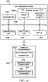
- Figure 2 is a block diagram of a design system 200 in accordance with one or more examples.
- Design system 200 is used to design circuit system 108 in Figure 1 .
- design system 200 includes network analyzer 202 and model generator 204. Model generator 204 and network analyzer 202 may be in communication with each other.
- Model generator 204 may be implemented using hardware, software, firmware, or a combination thereof. In one or more examples, model generator 204 is implemented using computer system 206. Computer system 206 may include a single computer or one or more computers in communication with each other.
- Network analyzer 202 is an instrument used to measure the parameters of electrical networks. In these examples, network analyzer 202 is used to generate S-parameter measurements that are used to generate one or more impedance curves. For example, network analyzer 202 may be used to generate baseline impedance information 210 for reference motor 211. Reference motor 211 may be, for example, motor 104 in Figure 1 or another type of electric motor. Baseline impedance information 210 is sent to model generator 204 for processing.
- baseline impedance information 210 includes S-parameter measurements that are made for reference motor 211. S-parameter measurements may be used to generate set of baseline impedance curves 212 for reference motor 211.
- model generator 204 may generate set of baseline impedance curves 212 using the S-parameter measurements generated for reference motor 211 by network analyzer 202.
- baseline impedance information 210 generated by network analyzer 202 includes set of baseline impedance curves 212, which may be generated using S-parameter measurements made by network analyzer 202.
- an impedance curve such as a baseline impedance curve of set of baseline impedance curves 212, tracks impedance versus frequency.
- Set of baseline impedance curves 212 may include, for example, common mode (CM) baseline impedance curve 214, differential mode (DM) baseline impedance curve 216, or both.
- CM common mode
- DM differential mode
- Model generator 204 uses baseline impedance information 210 received from network analyzer 202 to generate motor circuit model 218. For example, model generator 204 may identify set of baseline impedance curves 212 in baseline impedance information 210 or generate set of baseline impedance curves 212 using the S-parameter measurements in baseline impedance information 210. Model generator 204 approximates motor circuit model 218 using set of baseline impedance curves 212.
- Motor circuit model 218 is a model of an electronic circuit that represents the behavior of reference motor 211.
- motor circuit model 218 is generated such that motor circuit model 218 includes configuration 220 of a plurality of circuit devices 222.
- Circuit devices 222 include capacitors, inductors, and resistors.
- Configuration 220 defines how circuit devices 222 (e.g., the various capacitors, inductors, and resistors) of motor circuit model 218 are connected or coupled together.
- Configuration 220 of motor circuit model 218 may be used to model the behavior of different motors (e.g., at least two different types of motors) using different values for circuit devices 222.
- configuration 220 may be independent of the values assigned to each of circuit devices 222. Different testing may be used to identify which values to assign to each of circuit devices 222 to customize configuration 220 for different motors. But configuration 220 may itself be applicable to these different motors and not require any modification in how circuit devices 222 are arranged or electrically connected or coupled to each other.
- set of base formulas 224 is generated based on configuration 220 for motor circuit model 218.
- a formula of set of base formulas 224 may be generated based on at least a portion of configuration 220.
- Set of base formulas 224 may be used to identify the values for each of circuit devices 222 in configuration 220.
- configuration 220 and set of base formulas 224 may be used to provide a customized representation for that particular type of motor.
- a network analyzer which may be network analyzer 202 or a different network analyzer, may be used to generate motor impedance information 230.
- motor impedance information 230 may include S-parameter measurements that are used to generate set of motor impedance curves 232 or may include set of motor impedance curves 232.
- Model generator 204 receives motor impedance information 230 and uses motor impedance information 230 and set of base formulas 224 corresponding to configuration 220 for motor circuit model 218 to identify set of motor formulas 234. For example, values may be identified for set of base formulas 224 to transform set of base formulas 224 into set of motor formulas 234.
- Set of motor formulas 234 may then be used to develop suppression circuit model 228 for the particular motor, which may be motor 104.
- Suppression circuit model 228 may be used to build a circuit system, such as circuit system 108 in Figure 1 , that can be coupled to the particular motor, which may be motor 104, to reduce or suppress transient effects 110.
- the motor may be operated and a variation in an impedance of the motor within a range of frequencies that includes a resonant frequency of the motor reduced using a circuit system.
- suppression circuit model 228 is described above generally with respect to reducing variation in common mode impedance 114 of motor 104 in Figure 1 at and near the electrical resonance of motor 104. But in other examples, suppression circuit model 228 may be generated to additionally or instead, modify the differential mode impedance 115 of motor 104 at or near the electrical resonance of motor 104.
- FIG 3 is an illustration of a plot of common mode impedance in accordance with one or more examples.
- Plot 300 illustrates the common mode impedance for a reference motor, such as reference motor 211 in Figure 2 .
- Plot 300 includes x-axis 302 that represents frequency and y-axis 304 that represents common mode impedance.
- Curve 306 is a CM impedance curve.
- Curve 306 may be one example of an implementation for CM baseline impedance curve 214 in Figure 2 .
- curve 306 may be generated by a network analyzer, such as network analyzer 202 in Figure 2 , or a model generator, such as model generator 204 in Figure 2 .
- Portion 308 of curve 306 corresponds to range of frequencies 310, which may be one example of an implementation for range of frequencies 118 in Figure 1 .
- Range of frequencies 310 includes the resonant frequency of the reference motor.
- portion 308 of curve 306 has trough 312 at the resonant frequency of the reference motor. Trough 312 is the lowest common mode impedance for the reference motor.
- FIG 4 is an illustration of a plot of differential mode (DM) impedance in accordance with one or more examples.
- Plot 400 illustrates the DM impedance for a reference motor, such as reference motor 211 in Figure 2 .
- Plot 400 includes x-axis 402 that represents frequency and y-axis 404 that represents DM impedance.
- Curve 406 is a DM impedance curve.
- Curve 406 may be one example of an implementation for DM baseline impedance curve 216 in Figure 2 .
- curve 406 may be generated by a network analyzer, such as network analyzer 202 in Figure 2 , or a model generator, such as model generator 204 in Figure 2 .
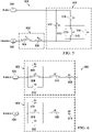
- Figure 5 is a schematic diagram of a first circuit model in accordance with one or more examples.
- first circuit model 500 includes structure portion 502 and phase portion 504.
- First circuit model 500 is one example of an implementation for at least a portion of motor circuit model 218 in Figure 2 .
- the configuration of structure portion 502 and phase portion 504 includes the circuit devices that are included in these portions, as well as their arrangement and connection to each other. This configuration may be determined based on plot 300 in Figure 3 . In particular, the shape of curve 306, the CM impedance curve, may be used to determine the configurations of structure portion 502 and phase portion 504.
- Structure portion 502 represents at least a portion of a motor that is electrically connected to structural component 505.
- Structural component 505 may be or may be a component of, for example, structure 103 in Figure 1 .
- Structure portion 502 includes inductor 506 and resistor 508.
- Phase portion 504 represents at least a portion of a motor that is electrically connected to phase line 509, which carries current of a corresponding phase.
- Phase portion 504 includes resistor 510, capacitor 512, capacitor 514, capacitor 516, and inductor 518.
- Equation (1) is one example of an implementation for a formula of set of base formulas 224 in Figure 2 .
- equation (1) may be a base formula that can be used to generically represent at least a portion of a motor circuit model. Equation (1) may then be solved, based on curve 306 in Figure 3 , for the values of the various resistors, capacitors, and inductors in structure portion 502 and phase portion 504. In one or more examples, solving for these values customizes equation (1) for the motor for which curve 306 in Figure 3 was generated, transforming this base formula into a motor formula, such as one of set of motor formulas 234 in Figure 2 .
- Figure 6 is a schematic diagram of a second motor circuit model in accordance with one or more examples.
- second circuit model 600 includes first phase portion 602 and second phase portion 604.
- first phase portion 602 and second phase portion 604 includes the circuit devices that are included in these portions, as well as their arrangement and connection to each other. This configuration may be determined based on plot 400 in Figure 4 . In particular, the shape of curve 406, the DM impedance curve, may be used to determine the configurations of first phase portion 602 and second phase portion 604.
- First phase portion 602 and second phase portion 604 are identical in this and other examples.
- First phase portion 602 includes resistor 605, resistor 606, inductor 608, inductor 610, and capacitor 612.
- Second phase portion 604 includes resistor 614, resistor 616, inductor 618, inductor 620, and capacitor 622.
- First phase portion 602 and second phase portion 604 each represent at least a portion of a motor that is electrically connected to a phase line.
- first phase portion 602 may be connected to phase line 624 and second phase portion 604 may be connected phase line 626.
- Phase line 624 and phase line 626 may each represent a current of a different phase.
- Equation (2) is one example of an implementation for a formula of set of base formulas 224 in Figure 2 .
- equation (2) may be a base formula that can be used to generically represent at least a portion of a motor circuit model. Equation (2) may then be solved, based on curve 406 in Figure 4 , for the values of the various resistors, capacitors, and inductors in first phase portion 602 and second phase portion 604. In one or more examples, solving for these values customizes equation (2) for the particular motor for which curve 406 was generated, transforming this base formula into a motor formula, such as one of set of motor formulas 234 in Figure 2 .
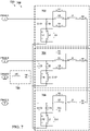
- Figure 7 is a schematic diagram of a motor circuit model in accordance with one or more examples.
- Motor circuit model 700 is one example of an implementation for motor circuit model 218 in Figure 2 .
- Motor circuit model 700 has configuration 701, which may be one example of an implementation for configuration 220 in Figure 2 .
- First circuit model 500 includes first phase branch 702, second phase branch 704, third phase branch 706, and structure branch 708.
- each of first phase branch 702, second phase branch 704, and third phase branch 706 corresponds to or is electrically connected to a different phase of a three-phase power supply for the motor. Further, each of first phase branch 702, second phase branch 704, and third phase branch 706 is formed using the configuration of circuit devices identical to the configuration of phase portion 504 of first circuit model 500 in Figure 5 as well as the configuration of circuit devices from first phase portion 602 (or second phase portion 604) of second circuit model 600 in Figure 6 .
- Structure branch 708 is formed using the configuration of circuit devices identical to the configuration of structure portion 502 of first circuit model 500 in Figure 5 .
- motor circuit model 700 is generated using circuit models (e.g., first circuit model 500 from Figure 5 and second circuit model 600 from Figure 6 ) that are determined using curve 306 in Figure 3 , which is the CM impedance curve, and curve 406 in Figure 4 , which is the DM impedance curve.
- circuit models e.g., first circuit model 500 from Figure 5 and second circuit model 600 from Figure 6
- curve 306 in Figure 3 which is the CM impedance curve
- curve 406 in Figure 4 which is the DM impedance curve.
- FIG 8 is a circuit diagram of a motor system in accordance with one or more examples.
- Circuit diagram 800 represents a motor system, such as, for example, motor system 100 in Figure 1 .
- Circuit diagram 800 includes power component 802, transmission line component 804, motor component 806, and suppression circuit model 808.
- Power component 802 represents the power supply for the motor system. In one or more examples, the power supply is considered part of the control system for the motor system.
- Transmission line component 804 represents the one or more transmission lines that carry current from the power supply to the motor, which is represented by motor component 806.
- motor component 806 includes a motor circuit model such as, for example, motor circuit model 700 in Figure 7 .
- Suppression circuit model 808 may be one example of an implementation for suppression circuit model 228 in Figure 2 .
- Suppression circuit model 808 may be determined using the motor circuit model of motor component 806.
- suppression circuit model 808 may be determined using a set of motor formulas that correspond to the motor circuit model, such as set of motor formulas 234 in Figure 2 .
- suppression circuit model 808 may be determined using equation (1) and equation (2) described above.
- suppression circuit model 808 includes resistor 810, resistor 812, and capacitor 814. In other examples, however, suppression circuit model 808 may include one or more other circuit devices in addition to or in place of resistor 810, resistor 812, capacitor 814, or a combination thereof.
- transmission line component 804 is shown connected between suppression circuit model 808 and motor component 806, and suppression circuit model 808 is shown connected between power component 802 and transmission line component 804.
- suppression circuit model 808 may be connected between transmission line component 804 and motor component 806.
- suppression circuit model 808 may be directly or indirectly connected to motor component 806 in some other manner.
- FIG 9 is an illustration of a plot comparing common mode impedance curves for a motor in accordance with one or more examples.
- Plot 900 includes x-axis 902 representing frequency and y-axis 904 representing common mode impedance.
- Curve 906 is a CM impedance curve for a motor.
- Curve 908 is a CM impedance curve for that same motor when the motor is coupled with a suppression circuit system, such as, for example, circuit system 108 in Figure 1 .
- This suppression circuit system may follow a model similar to suppression circuit model 228 described with respect to Figure 2 or suppression circuit model 808 in Figure 8 .
- the suppression circuit system reduces the variation of common mode impedance within range of frequencies 910.
- Curve 906 has its trough (or lowest impedance) at resonant frequency 912 of the motor.
- the common mode impedance at resonant frequency 912 is raised. This raising of the common mode impedance at resonant frequency 912 reduces the slope of curve 906 at the frequencies leading up to resonant frequency 912.
- Range of frequencies 910 includes frequencies below and above resonant frequency 912. In one or more examples, range of frequencies 910 includes a frequency band of 1 megahertz that is centered around resonant frequency 912. In other examples, range of frequencies 910 includes a frequency band of 2 megahertz that is centered around resonant frequency 912. In still other examples, range of frequencies 910 includes a frequency band of 0.5 megahertz, 3 megahertz, or some other range that is centered around resonant frequency 912. In some cases, range of frequencies 910 is not centered around resonant frequency 912 but still includes resonant frequency 912.
- Figure 10 is an illustration of a plot comparing spectral content of common mode current for a motor in accordance with one or more examples.
- Plot 1000 is based on the same motor on which plot 900 is based.
- Plot 1000 includes x-axis 1002 representing frequency and y-axis 1004 representing decibel amperes (dBA).
- Spectral content 1006 is the spectral content of the CM current for the motor.
- Spectral content 1008 is the spectral content of the CM current for that same motor when the motor is coupled with a suppression circuit system, such as, for example, circuit system 108 in Figure 1 .
- Spectral content 1008 shows that using the suppression circuit system, noise is reduced within range of frequencies 1010 that includes resonant frequency 1012 of the motor.
- FIG 11 is a flowchart of a process for controlling effects of a motor in accordance with an example.
- Process 1100 may be implemented using, for example, circuit system 108 and motor 104 described with respect to Figure 1 .
- a circuit system is coupled to a motor (operation 1102).
- the motor is an electric motor.
- the motor is a permanent magnet motor (e.g., a permanent magnet DC motor).
- a variation in an impedance of the motor within a range of frequencies that includes a resonant frequency of the motor is reduced using the circuit system (operation 1104). Reducing the variation in the impedance of the motor reduces transient effects generated by the motor at or near electrical resonance of the motor.
- operation 1104 is performed by the circuit system raising a common mode impedance of the motor at the resonant frequency of the motor.
- reducing the variation in the impedance includes reducing a difference between a lowest common mode impedance and a highest common mode impedance of the motor within the range of frequencies to thereby suppress noise generated by the motor at and near electrical resonance.
- Figure 12 is a flowchart of a process for developing a circuit system to control effects generated by a motor in accordance with an example.
- Process 1200 in Figure 12 may be implemented using, for example, design system 200 in Figure 2 to develop circuit system 108 in Figure 1 .
- Baseline impedance information is generated for a reference motor (operation 1202). Operation 1202 may be performed using a network analyzer.
- the baseline impedance information includes S-parameter measurements that can be used to generate a set of baseline impedance curves. In other examples, the baseline impedance information includes the set of baseline impedance curves.
- a motor circuit model of the reference motor is generated using the baseline impedance information for the reference motor (operation 1204).
- operation 1204 may include using the shape of each baseline impedance curve in the set of baseline impedance curves to generate the motor circuit model.
- the set of baseline impedance curves may include a CM impedance curve and a DM impedance curve that are used to determine different portions of the configuration of the motor circuit model.
- operation 1204 includes generating the set of baseline curves using the S-parameter measurements.
- a suppression circuit model of the circuit system is generated using the motor circuit model such that the circuit system is configured to reduce a variation in an impedance of a motor within a range of frequencies that includes a resonant frequency of the motor when the circuit system is coupled to the motor (operation 1206).
- the suppression circuit model generated may be used to build the circuit system.
- the suppression circuit model identifies the set of circuit devices and the configuration for the set of circuit devices that are needed to suppress transient effects generated by the motor at electrical resonance.
- the motor in operation 1206 is the reference motor. In other examples, the motor in operation 1206 is a different motor or a different type of motor.
- Figure 13 is a flowchart of a process for developing a circuit system to control effects of a motor in accordance with an example embodiment.
- Process 1300 in Figure 13 may be implemented using, for example, design system 200 in Figure 2 to develop circuit system 108 in Figure 1 .
- process 1300 may be used to implement operation 1204 in Figure 12 and generate a suppression circuit model for the circuit system.
- Process 1300 may begin by identifying a motor CM impedance curve for a motor (operation 1302).
- the motor CM impedance curve may be for example, one curve in set of motor impedance curves 232 in Figure 2 .
- operation 1302 is performed by identifying the motor CM impedance curve from motor impedance information generated for the motor using a network analyzer.
- the motor impedance information may be, for example, motor impedance information 230.
- the motor CM impedance curve is used with a motor circuit model corresponding to a reference motor to form a customized motor circuit model for the motor (operation 1304).
- the motor circuit model may be, for example, motor circuit model 218 in Figure 2 .
- the motor circuit model is the motor circuit model generated for the reference motor in operation 1204 in Figure 12 .
- the motor described in process 1300 may be the same reference motor from Figure 12 or a different motor.
- operation 1304 may be performed by solving for a set of base formulas corresponding to the motor circuit model using the motor CM impedance curve.
- the set of base formulas is defined based on the configuration of the motor circuit model. Solving for the set of base formulas includes identifying values for the various circuit devices that make up the configuration of the motor circuit model. The motor circuit model having these values for the circuit devices in the motor circuit model is considered customized for the motor.
- the customized motor circuit model is used to generate a suppression circuit model for the motor (operation 1306).
- Operation 1306 may be performed by, for example, determining which circuit, when coupled to the motor, would reduce a variation in an impedance of the motor within a range of frequencies that includes the resonant frequency of the motor.
- the suppression circuit model may be generated to modify the impedance of the motor within the range of frequencies in some other manner.
- FIG 14 is a flowchart of a process for controlling effects of a motor in accordance with an example.
- Process 1400 in Figure 14 may be implemented using, for example, circuit system 108 in Figure 1 and motor 104 in Figure 1 .
- a circuit system is coupled to a motor (operation 1402).
- the motor is an electric motor.
- the motor is a permanent magnet motor (e.g., a permanent magnet DC motor).
- the impedance of the motor at electrical resonance is raised using the circuit system to above a baseline impedance of the motor at electrical resonance (operation 1404).
- the impedance and baseline impedance are common mode impedance.
- the baseline impedance may be the impedance of the motor when the circuit system is not coupled to the motor.
- Operation 1404 may be performed to raise the impedance above the baseline impedance by at least a selected amount.
- the circuit system is used to raise the magnitude of the impedance by at least, for example, 20 Ohms, 30 Ohms, 50 Ohms, 60 Ohms, 5 Ohms, 80 Ohms, 100 Ohms, 150 Ohms, or some other number of Ohms.
- the circuit system is generated so as to raise the magnitude of the impedance by at least, for example, a number of Ohms selected between about 20 Ohms and about 1000 Ohms (or 20 Ohms and 1000 Ohms).
- raising the impedance of the motor at electrical resonance includes raising the common mode impedance of the motor at the resonant frequency of the motor. Further, in one or more examples, raising the impedance of the motor at electrical resonance may also include raising the common mode impedance of the motor within a range of frequencies around the resonant frequency. This type of modification may result in a flattening (or at least reduction of slope/steepness) at the dip in the common mode impedance curve corresponding to the motor.
- Data processing system 1500 may be used to implement computer system 206 in Figure 2 .
- data processing system 1500 includes communications framework 1502, which provides communications between processor unit 1504, storage devices 1506, communications unit 1508, input/output unit 1510, and display 1512.
- communications framework 1502 may be implemented as a bus system.
- Processor unit 1504 is configured to execute instructions for software to perform a number of operations.
- Processor unit 1504 may comprise a number of processors, a multi-processor core, and/or some other type of processor, depending on the implementation.
- processor unit 1504 may take the form of a hardware unit, such as a circuit system, an application specific integrated circuit (ASIC), a programmable logic device, or some other suitable type of hardware unit.
- ASIC application specific integrated circuit
- Storage devices 1506 may be in communication with processor unit 1504 through communications framework 1502.
- a storage device also referred to as a computer-readable storage device, is any piece of hardware capable of storing information on a temporary and/or permanent basis. This information may include, but is not limited to, data, program code, and/or other information.
- Memory 1514 and persistent storage 1516 are examples of storage devices 1506.
- Memory 1514 may take the form of, for example, a random-access memory or some type of volatile or non-volatile storage device.
- Persistent storage 1516 may comprise any number of components or devices.
- persistent storage 1516 may comprise a hard drive, a flash memory, a rewritable optical disk, a rewritable magnetic tape, or some combination of the above.
- the media used by persistent storage 1516 may or may not be removable.
- Communications unit 1508 allows data processing system 1500 to communicate with other data processing systems and/or devices. Communications unit 1508 may provide communications using physical and/or wireless communications links.
- Input/output unit 1510 allows input to be received from and output to be sent to other devices connected to data processing system 1500.
- input/output unit 1510 may allow user input to be received through a keyboard, a mouse, and/or some other type of input device.
- input/output unit 1510 may allow output to be sent to a printer connected to data processing system 1500.
- Display 1512 is configured to display information to a user.
- Display 1512 may comprise, for example, without limitation, a monitor, a touch screen, a laser display, a holographic display, a virtual display device, and/or some other type of display device.
- processor unit 1504 may perform the processes of the different examples using computer-implemented instructions. These instructions may be referred to as program code, computer-usable program code, or computer-readable program code and may be read and executed by one or more processors in processor unit 1504.
- program code 1518 is located in a functional form on computer-readable media 1520, which is selectively removable, and may be loaded onto or transferred to data processing system 1500 for execution by processor unit 1504.
- Program code 1518 and computer-readable media 1520 together form computer program product 1522.
- computer-readable media 1520 may be computer-readable storage media 1524 or computer-readable signal media 1526.
- Computer-readable storage media 1524 is a physical or tangible storage device used to store program code 1518 rather than a medium that propagates or transmits program code 1518.
- Computer-readable storage media 1524 may be, for example, without limitation, an optical or magnetic disk or a persistent storage device that is connected to data processing system 1500.
- program code 1518 may be transferred to data processing system 1500 using computer-readable signal media 1526.
- Computer-readable signal media 1526 may be, for example, a propagated data signal containing program code 1518. This data signal may be an electromagnetic signal, an optical signal, and/or some other type of signal that can be transmitted over physical and/or wireless communications links.
- data processing system 1500 in Figure 15 is not meant to provide architectural limitations to the manner in which the examples may be implemented.
- the different examples may be implemented in a data processing system that includes components in addition to or in place of those illustrated for data processing system 1500. Further, components shown in Figure 15 may be varied from the illustrative examples shown.
- aircraft manufacturing and service method 1600 may be described in the context of aircraft manufacturing and service method 1600 as shown in Figure 16 and aircraft 1700 as shown in Figure 17 .
- Figure 16 an illustration of an aircraft manufacturing and service method is depicted in accordance with an example.
- aircraft manufacturing and service method 1600 may include specification and design 1602 of aircraft 1700 in Figure 17 and material procurement 1604.
- aircraft 1700 in Figure 17 During production, component and subassembly manufacturing 1606 and system integration 1608 of aircraft 1700 in Figure 17 takes place. Thereafter, aircraft 1700 in Figure 17 may go through certification and delivery 1610 in order to be placed in service 1612. While in service 1612 by a customer, aircraft 1700 in Figure 17 is scheduled for routine maintenance and service 1614, which may include modification, reconfiguration, refurbishment, and other maintenance or service.
- Each of the processes of aircraft manufacturing and service method 1600 may be performed or carried out by a system integrator, a third party, and/or an operator.
- the operator may be a customer.
- a system integrator may include, without limitation, any number of aircraft manufacturers and major-system subcontractors
- a third party may include, without limitation, any number of vendors, subcontractors, and suppliers
- an operator may be an airline, a leasing company, a military entity, a service organization, and so on.
- aircraft 1700 is produced by aircraft manufacturing and service method 1600 in Figure 16 and may include airframe 1702 with plurality of systems 1704 and interior 1706.
- systems 1704 include one or more of propulsion system 1708, electrical system 1710, hydraulic system 1712, and environmental system 1714. Any number of other systems may be included.
- propulsion system 1708 includes one or more of propulsion system 1708, electrical system 1710, hydraulic system 1712, and environmental system 1714. Any number of other systems may be included.
- an aerospace example is shown, different examples may be applied to other industries, such as the automotive industry.
- Apparatuses and methods embodied herein may be employed during at least one of the stages of aircraft manufacturing and service method 1600 in Figure 16 .
- fabrication system 164 from Figure 1 may be used to fabricate tool 162 during any one of the stages of aircraft manufacturing and service method 1600.
- fabrication system 164 from Figure 1 may be used to fabricate tool 162 during at least one of component and subassembly manufacturing 1606, system integration 1608, routine maintenance and service 1614, or some other stage of aircraft manufacturing and service method 1600.
- fabrication system 164 from Figure 1 may be used to fabricate tool 162 for use in fabricating composite parts for at least one of airframe 1702 or interior 1706 of aircraft 1700 in Figure 17 .
- components or subassemblies produced in component and subassembly manufacturing 1606 in Figure 16 may be fabricated or manufactured in a manner similar to components or subassemblies produced while aircraft 1700 is in service 1612 in Figure 16 .
- one or more apparatus embodiments, method embodiments, or a combination thereof may be utilized during production stages, such as component and subassembly manufacturing 1606 and system integration 1608 in Figure 16 .
- One or more apparatus embodiments, method embodiments, or a combination thereof may be utilized while aircraft 1700 is in service 1612 and/or during maintenance and service 1614 in Figure 16 .
- the use of a number of the different examples may expedite or substantially expedite the assembly of and/or reduce the cost of aircraft 1700.
- one or more embodiments described herein may be used as part of propulsion system 1708 of aircraft 1700.
- each block in the flowcharts or block diagrams may represent a module, a segment, a function, and/or a portion of an operation or step.
- the phrase "at least one of,” when used with a list of items, means different combinations of one or more of the listed items may be used and only one of the items in the list may be needed.
- the item may be a particular object, thing, step, operation, process, or category.
- "at least one of” means any combination of items or number of items may be used from the list, but not all of the items in the list may be required.
- "at least one of item A, item B, or item C" or "at least one of item A, item B, and item C” may mean item A; item A and item B; item B; item A, item B, and item C; item B and item C; or item A and C.
- "at least one of item A, item B, or item C" or “at least one of item A, item B, and item C” may mean, but is not limited to, two of item A, one of item B, and ten of item C; four of item B and seven of item C; or some other suitable combination.
- a system comprising: a circuit system configured to be coupled to a motor such that the circuit system reduces a variation in an impedance of the motor within a range of frequencies that includes a resonant frequency of the motor.
- Clause 3 The system of clause 1 or 2, wherein the circuit system is configured to reduce the variation in the impedance by reducing a difference between a lowest impedance and a highest impedance of the motor within the range of frequencies to thereby suppress noise generated by the motor.
- Clause 4 The system of any of clauses 1 to 3, wherein the circuit system is configured to reduce the variation in the impedance by reducing a slope of a portion of a common mode impedance curve corresponding to the motor between the resonant frequency and a lower frequency within the range of frequencies.
- circuit system comprises: a set of circuit devices including at least one of a resistor, a capacitor, or an inductor.
- Clause 7 The system of any of clauses 1 to 6, further comprising: the motor.
- Clause 8 The system of clause 7, further comprising: a structure associated with the motor, wherein the circuit system is configured to suppress transient effects driven onto the structure by the motor.
- a motor system comprising: an electric motor; and a circuit system coupled to the electric motor, wherein the circuit system is configured to reduce a difference between a lowest common mode impedance and a highest common mode impedance of the electric motor within a range of frequencies that includes a resonant frequency of the electric motor.
- Clause 10 The motor system of clause 9, wherein the circuit system is configured to reduce the difference between the lowest common mode impedance and the highest common mode impedance of the electric motor within the range of frequencies to thereby suppress transient effects generated at an electrical resonance of the electric motor.
- a method for controlling effects generated by a motor comprising: coupling a circuit system to the motor; and reducing a variation in an impedance of the motor within a range of frequencies that includes a resonant frequency of the motor using the circuit system.
- reducing the variation comprises: reducing the variation in the impedance of the motor within the range of frequencies using the circuit system to thereby suppress transient effects driven onto a structure associated with the motor at an electrical resonance of the motor.
- Clause 13 The method of clause 11 or 12, further comprising: generating a set of baseline impedance curves corresponding to the motor; and generating a motor circuit model of the motor using the set of baseline impedance curves.
- generating the set of baseline impedance curves comprises: generating a baseline common mode impedance curve and a baseline differential mode impedance curve corresponding to the motor.
- Clause 15 The method of clause 13 or 14, further comprising: generating a suppression circuit model for the circuit system based, wherein the suppression circuit model is designed to reduce a difference between a lowest common mode impedance and a highest common mode impedance of the motor within the range of frequencies that includes the resonant frequency.
- Clause 16 The method of clause 15, further comprising: building the circuit system based on the suppression circuit model using a set of circuit devices.
- a system comprising: a network analyzer configured to generate baseline impedance information for a reference motor; and a model generator configured to generate a motor circuit model of the reference motor using the baseline impedance information for the reference motor; and generate a suppression circuit model of a circuit system using the motor circuit model such that the circuit system is configured to reduce a variation in an impedance of a motor within a range of frequencies that includes a resonant frequency of the motor when the circuit system is coupled to the motor.
- Clause 23 The system of any of clauses 17 to 22, wherein the model generator is configured to generate a set of base formulas corresponding to a configuration of the motor circuit model and to identify values for a plurality of circuit devices in the motor circuit model using the baseline impedance information to transform the set of base formulas into a set of motor formulas.
- Clause 25 The system of any of clauses 17 to 24, wherein the range of frequencies includes a band of about 1 megahertz around the resonant frequency.
- Clause 26 The system of any of clauses 17 to 25, wherein the range of frequencies includes a band of about 2 megahertz around the resonant frequency.
- a method for developing a circuit system to control effects generated by a motor comprising: generating baseline impedance information for a reference motor; generating a motor circuit model of the reference motor using the baseline impedance information for the reference motor; and generating a suppression circuit model of the circuit system using the motor circuit model such that the circuit system is configured to reduce a variation in an impedance of the motor within a range of frequencies that includes a resonant frequency of the motor when the circuit system is coupled to the motor.
- Clause 28 The method of clause 27, further comprising: building the circuit system based on the suppression circuit model; and coupling the circuit system to the motor.
- a non-transitory computer-readable medium storing computer instructions thereon, the non-transitory computer-readable medium comprising machine-executable code that, when run by at least one machine, causes the at least one machine to: generate a set of baseline impedance curves corresponding to a motor using a network analyzer; generate a motor circuit model of the motor using the set of baseline impedance curves; and generate a suppression circuit model for a circuit system using the motor circuit model such that the circuit system is configured to reduce a variation in the impedance of the motor within a range of frequencies that includes a resonant frequency of the motor when the circuit system is coupled to the motor.
- a method for controlling effects generated by a motor comprising: operating the motor; and reducing a variation in an impedance of the motor within a range of frequencies that includes a resonant frequency of the motor using a circuit system.
Landscapes
- Engineering & Computer Science (AREA)
- Power Engineering (AREA)
- Microelectronics & Electronic Packaging (AREA)
- Aviation & Aerospace Engineering (AREA)
- Control Of Electric Motors In General (AREA)
- Electric Propulsion And Braking For Vehicles (AREA)
- Control Of Ac Motors In General (AREA)
Abstract
Description
- This disclosure generally relates to electric motors and, more particularly, to systems and methods for controlling the effects of an electric motor on its surrounding environment using a circuit system coupled to the electric motor.
- An electric motor is a machine that converts electrical energy into mechanical energy. The various different types of electric motors include direct current (DC) motors, alternating current (AC) motors, magnet-based motors (e.g., a permanent magnet motor, etc.), induction motors (e.g., a three-phase induction motor), brushed motors, brushless motors, as well as other types of motors.
- In some cases, parasitics are present within an electric motor. These parasitics, which may include parasitic capacitances, parasitic resistances, parasitic inductances, or a combination thereof, are a result of motor design, assembly, and/or installation. The broad spectral content associated with electrical switching of the control system of the electric motor may excite these parasitics. This excitation, in turn, may drive transient effects (e.g., transient voltages, transient currents, etc.) onto structure surrounding the electric motor at electrical resonance. These transient effects can have undesired consequences. For example, when the electric motor is used in a vehicle, the transient effects may generate undesired interference with other components or systems of the vehicle.
- A system comprises a circuit system configured to be coupled to a motor such that the circuit system reduces a variation in an impedance of the motor within a range of frequencies that includes a resonant frequency of the motor.
- A motor system comprises an electric motor and a circuit system coupled to the electric motor. The circuit system is configured to reduce a difference between a lowest common mode (CM) impedance and a highest common mode impedance of the electric motor within a range of frequencies that includes a resonant frequency of the electric motor.
- A method for controlling effects generated by a motor is provided. A circuit system is coupled to a motor. A variation in an impedance of the motor is reduced within a range of frequencies that includes a resonant frequency of the motor using the circuit system.
- A system comprises a network analyzer and a model generator. The network analyzer is configured to generate baseline impedance information for a reference motor. The model generator is configured to generate a motor circuit model of the reference motor using the baseline impedance information for the reference motor. The model generator is further configured to generate a suppression circuit model of a circuit system using the motor circuit model such that the circuit system is configured to reduce a variation in an impedance of a motor within a range of frequencies that includes a resonant frequency of the motor when the circuit system is coupled to the motor.
- A method is provided for developing a circuit system to control effects generated by a motor. Baseline impedance information is generated for a reference motor. A motor circuit model of the reference motor is generated using the baseline impedance information for the reference motor. A suppression circuit model of the circuit system is generated using the motor circuit model such that the circuit system is configured to reduce a variation in an impedance of the motor within a range of frequencies that includes a resonant frequency of the motor when the circuit system is coupled to the motor.
- A non-transitory computer-readable medium, storing computer instructions thereon, is provided. The non-transitory computer-readable medium comprises machine-executable code that, when run by at least one machine, causes the at least one machine to: generate a set of baseline impedance curves corresponding to the motor using a network analyzer; generate a motor circuit model of the motor using the set of baseline impedance curves; and generate a suppression circuit model for a circuit system using the motor circuit model such that the circuit system is configured to reduce a variation in the impedance of the motor within a range of frequencies that includes a resonant frequency of the motor when the circuit system is coupled to the motor.
- The features and functions can be achieved independently in various embodiments of the present disclosure or may be combined in yet other embodiments in which further details can be seen with reference to the following description and drawings.
- Examples will now be described with reference to the accompanying drawings in which:
-
Figure 1 is a block diagram of a motor system of a vehicle; -
Figure 2 is a block diagram of a design system; -
Figure 3 is an illustration of a common mode impedance plot for a reference motor; -
Figure 4 is an illustration of a differential mode impedance plot for a reference motor embodiments; -
Figure 5 is a schematic diagram of a section of a motor circuit model; -
Figure 6 is a schematic diagram of a section of a motor circuit model; -
Figure 7 is a schematic diagram of a motor circuit model; -
Figure 8 is a schematic diagram of a motor system; -
Figure 9 is an illustration of a plot comparing common mode impedance curves for a motor; -
Figure 10 is an illustration of a plot comparing spectral content of common mode current for a motor; -
Figure 11 is a flowchart of a process for controlling effects of a motor; -
Figure 12 is a flowchart of a process for developing a circuit system to control effects of a motor; -
Figure 13 is a flowchart of a process for developing a circuit system to control effects of a motor; -
Figure 14 is a flowchart of a process for controlling effects of a motor; -
Figure 15 is a block diagram of a data processing system; -
Figure 16 is an illustration of an aircraft manufacturing and service method; and -
Figure 17 is a block diagram of an aircraft. - The examples described below provide methods and systems for controlling the effects of motors and, in particular, electric motors. In particular, the various examples provide methods and systems for reducing or suppressing transient effects generated at or near electrical resonance within a motor. These transient effects may include transient voltages and transient currents.
- The examples described herein recognize and take into account that certain types of vehicles use electric motors to generate high power levels. For example, various types of aircraft (e.g., electric vertical takeoff and landing (eVTOL) aircraft) may be battery-powered and generate lift via multiple electric motors. These motors may be controlled by, for example, electric speed controllers (ESC) that excite electrical resonances within the motors. This electrical resonance, however, may generate transient effects, such as undesired high amplitude CM voltages, CM currents, or both that are driven into the motor's surrounding environment. The surrounding environment may include structure, such as the frame or chassis of the vehicle.
- Because the electrical resonance of a motor is generally based on the physical construction of that motor, different motors have different electrical resonances. Accordingly, understanding the transient effects produced at and near the resonant frequency of a particular motor or type of motor may be challenging. Thus, the examples provide methods and systems for generating a motor circuit model having a configuration that can be generally used to represent different types of motors. This motor circuit model can then be customized to represent individual motors. Further, a motor circuit model customized for a particular motor is then used to design and develop a circuit system for controlling (e.g., reducing or suppressing) the transient effects that may be generated by that particular motor at and near the resonant frequency for the motor.
- In particular, the various examples describe a circuit system that modifies the impedance of a motor. More specifically, the circuit system reduces a variation in an impedance (e.g., CM impedance) of the motor within a range of frequencies that includes the resonant frequency of the motor. Reducing this variation, which raises the common mode impedance at the resonant frequency, reduces or suppresses transient effects that may be produced by the motor.
- This type of circuit system may be lower in cost, weight, or both as compared to using transmission line filters, decoupling capacitors, CM chokes, ferrites, etc. Further, this type of circuit system may be easily and effectively adapted for use with multiple motors. Accordingly, this type of circuit system may be particularly well-suited for use in controlling the effects of electric motors used in light-weight vehicles that require high power.
- Thus, in some examples, a system comprises a circuit system configured to be coupled to a motor. The circuit system is coupled to the motor such that the circuit system reduces a variation in an impedance of the motor within a range of frequencies that includes a resonant frequency of the motor. This circuit system is designed and developed using a motor circuit model that represents the motor. This configuration of this motor circuit model may be used with respect to other motors of similar or different types, to design and develop circuit systems for coupling to the other motors.
- Referring now to the figures,
Figure 1 is a block diagram of amotor system 100 in accordance with one or more examples. In one or more examples,motor system 100 may be used to generate motive power forplatform 101.Platform 101 may take different forms. - In one or more examples,
platform 101 takes the form ofvehicle 102.Vehicle 102 may take the form of, for example, without limitation, an aircraft, a spacecraft, an unmanned aerial vehicle (UAV), another type of aerospace vehicle, a ground vehicle, or other type of vehicle. In other examples,platform 101 may be a piece of machinery, a tool, an electric device, equipment, some other type of platform that operates using motive power, or a combination thereof. -
Motor system 100 may be coupled toplatform 101 in different ways. For example,motor system 100 may be physically associated withstructure 103 andstructure 103 may be physically associated withmotor system 100. This physical association may be provided via directly or indirectly couplingmotor system 100 to structure 103 ofplatform 101.Structure 103 may include a housing, a frame (e.g., a chassis), one or more structural members, a mounting structure or device, some other type of structure, or a combination thereof. - When
platform 101 takes the form ofvehicle 102,structure 103 may include a chassis ofvehicle 102.Motor system 100 may be associated with the chassis by at least a portion ofmotor system 100 being mounted (or directly attached) to the chassis. In other examples,motor system 100 may be indirectly attached to the chassis. For example,motor system 100 may be attached to another structural component that is itself attached to the chassis directly or indirectly. -
Motor system 100 includesmotor 104,control system 106, andcircuit system 108.Motor 104 is an electric motor and may take any of a number of different forms. For example, the electric motor may be a direct current (DC) motor, an alternating current (AC) motor, an electromagnetic motor, a magnet-based motor (e.g., a permanent magnet motor, etc.), an induction motor (e.g., a three-phase induction motor), a brushed motor, a brushless motor, or some other type of motor. In some cases, the electric motor may be a combination or integration of two or more motors, which may be of the same type or of different types. -
Control system 106 is used to control the operation ofmotor 104.Control system 106 may be implemented using hardware, software, firmware, or a combination thereof. In one or more examples,control system 106 is separate from but coupled tomotor 104. For example, set oftransmission lines 109 may connectcontrol system 106 tomotor 104. In other examples, at least a portion ofcontrol system 106 is implemented within or integrated as part ofmotor 104. -
Control system 106 controls the electrical energy that is driven intomotor 104. In one or more examples,control system 106 includes variable speed control. In some examples,control system 106 controls and drives the operation ofmotor 104 using any number of power semiconductor devices (e.g., insulated gate bipolar transistor (IGBT) devices, metal-oxide-semiconductor field-effect transistor (MOSFET) devices, etc.). -
Circuit system 108 may be considered separate frommotor 104 and separate fromcontrol system 106 but coupled tomotor 104,control system 106, or both. In other examples, at least a portion ofcircuit system 108 may be implemented within or otherwise integrated as part ofcontrol system 106,motor 104, or both. -
Circuit system 108 is used to controltransient effects 110 ofmotor 104.Transient effects 110 may include transient currents, transient voltages, another type of transient electromagnetic effect, or a combination thereof. In one or more examples,transient effects 110 are driven ontostructure 103 ofplatform 101 and affectplatform 101 in an undesired manner. For example, transient currents, transient voltages, or both may generate radiofrequency interference, interfere with power systems, interfere with communications, interfere with platform systems or operations (e.g., avionic operations, etc.), generate undesired noise, or a combination thereof. - In one or more examples,
circuit system 108 is used to reduce (or suppress)transient effects 110 by controlling one or more characteristics ofmotor 104. For example,circuit system 108 may be used to controlimpedance 112 ofmotor 104.Impedance 112 includes common mode (CM)impedance 114,differential mode impedance 115, or both. The amount of common mode (CM)impedance 114 of themotor 104 varies within a range of frequencies at which the motor operates. By coupling thecircuit system 108 with themotor 104 and its electrical windings in a manner for controllingimpedance 112 ofmotor 104,circuit system 108 can reduce (or suppress)transient effects 110 onstructure 103 ofvehicle 102 that may arise due to undesired levels ofimpedance 112. - For example,
common mode impedance 114 may be lowest atresonant frequency 116 ofmotor 104. Parasitics (e.g., parasitic capacitances, parasitic inductances, etc.) that exist withinmotor 104 may cause the steep drop incommon mode impedance 114 that occurs near and at resonant frequency (fr) 116. This drop incommon mode impedance 114 may produce common mode noise that may be driven ontostructure 103 in the form oftransient effects 110.Circuit system 108 is used to raisecommon mode impedance 114 at and nearresonant frequency 116 to reduce (or suppress) suchtransient effects 110. - In one or more examples,
circuit system 108 raisescommon mode impedance 114 within range offrequencies 118 that includesresonant frequency 116. In particular,circuit system 108 may reduce a variation incommon mode impedance 114 within range offrequencies 118. For example,circuit system 108 may reduce a difference between a lowest impedance and a highest impedance ofcommon mode impedance 114 ofmotor 104 within range offrequencies 118. -
Figure 2 is a block diagram of adesign system 200 in accordance with one or more examples.Design system 200 is used to designcircuit system 108 inFigure 1 . In one or more examples,design system 200 includesnetwork analyzer 202 andmodel generator 204.Model generator 204 andnetwork analyzer 202 may be in communication with each other. -
Model generator 204 may be implemented using hardware, software, firmware, or a combination thereof. In one or more examples,model generator 204 is implemented usingcomputer system 206.Computer system 206 may include a single computer or one or more computers in communication with each other. -
Network analyzer 202 is an instrument used to measure the parameters of electrical networks. In these examples,network analyzer 202 is used to generate S-parameter measurements that are used to generate one or more impedance curves. For example,network analyzer 202 may be used to generatebaseline impedance information 210 forreference motor 211.Reference motor 211 may be, for example,motor 104 inFigure 1 or another type of electric motor.Baseline impedance information 210 is sent tomodel generator 204 for processing. - In one or more examples,
baseline impedance information 210 includes S-parameter measurements that are made forreference motor 211. S-parameter measurements may be used to generate set of baseline impedance curves 212 forreference motor 211. For example,model generator 204 may generate set of baseline impedance curves 212 using the S-parameter measurements generated forreference motor 211 bynetwork analyzer 202. - In other examples,
baseline impedance information 210 generated bynetwork analyzer 202 includes set of baseline impedance curves 212, which may be generated using S-parameter measurements made bynetwork analyzer 202. - As used herein, an impedance curve, such as a baseline impedance curve of set of baseline impedance curves 212, tracks impedance versus frequency. Set of baseline impedance curves 212 may include, for example, common mode (CM)
baseline impedance curve 214, differential mode (DM)baseline impedance curve 216, or both. -
Model generator 204 usesbaseline impedance information 210 received fromnetwork analyzer 202 to generatemotor circuit model 218. For example,model generator 204 may identify set of baseline impedance curves 212 inbaseline impedance information 210 or generate set of baseline impedance curves 212 using the S-parameter measurements inbaseline impedance information 210.Model generator 204 approximatesmotor circuit model 218 using set of baseline impedance curves 212. -
Motor circuit model 218 is a model of an electronic circuit that represents the behavior ofreference motor 211. In one or more examples,motor circuit model 218 is generated such thatmotor circuit model 218 includesconfiguration 220 of a plurality ofcircuit devices 222.Circuit devices 222 include capacitors, inductors, and resistors.Configuration 220 defines how circuit devices 222 (e.g., the various capacitors, inductors, and resistors) ofmotor circuit model 218 are connected or coupled together. -
Configuration 220 ofmotor circuit model 218 may be used to model the behavior of different motors (e.g., at least two different types of motors) using different values forcircuit devices 222. For example,configuration 220 may be independent of the values assigned to each ofcircuit devices 222. Different testing may be used to identify which values to assign to each ofcircuit devices 222 to customizeconfiguration 220 for different motors. Butconfiguration 220 may itself be applicable to these different motors and not require any modification in howcircuit devices 222 are arranged or electrically connected or coupled to each other. - In one or more examples, set of
base formulas 224 is generated based onconfiguration 220 formotor circuit model 218. For example, a formula of set ofbase formulas 224 may be generated based on at least a portion ofconfiguration 220. Set ofbase formulas 224 may be used to identify the values for each ofcircuit devices 222 inconfiguration 220. - For a particular type of motor,
configuration 220 and set ofbase formulas 224 may be used to provide a customized representation for that particular type of motor. For example, a network analyzer, which may benetwork analyzer 202 or a different network analyzer, may be used to generatemotor impedance information 230. Similar tobaseline impedance information 210,motor impedance information 230 may include S-parameter measurements that are used to generate set of motor impedance curves 232 or may include set of motor impedance curves 232. -
Model generator 204 receivesmotor impedance information 230 and usesmotor impedance information 230 and set ofbase formulas 224 corresponding toconfiguration 220 formotor circuit model 218 to identify set ofmotor formulas 234. For example, values may be identified for set ofbase formulas 224 to transform set ofbase formulas 224 into set ofmotor formulas 234. - Set of
motor formulas 234 may then be used to developsuppression circuit model 228 for the particular motor, which may bemotor 104.Suppression circuit model 228 may be used to build a circuit system, such ascircuit system 108 inFigure 1 , that can be coupled to the particular motor, which may bemotor 104, to reduce or suppresstransient effects 110. Thus, in one or more examples, the motor may be operated and a variation in an impedance of the motor within a range of frequencies that includes a resonant frequency of the motor reduced using a circuit system. - The block diagrams of
Figures 1 and2 are not meant to imply physical or architectural limitations to the manner in which examples may be implemented. Other components in addition to or in place of the ones illustrated may be used. Some components may be optional. Further, the blocks are presented to illustrate functional components. One or more of these blocks may be combined, divided, or combined and divided into different blocks when implemented in examples. - For example,
suppression circuit model 228 is described above generally with respect to reducing variation incommon mode impedance 114 ofmotor 104 inFigure 1 at and near the electrical resonance ofmotor 104. But in other examples,suppression circuit model 228 may be generated to additionally or instead, modify thedifferential mode impedance 115 ofmotor 104 at or near the electrical resonance ofmotor 104. -
Figure 3 is an illustration of a plot of common mode impedance in accordance with one or more examples.Plot 300 illustrates the common mode impedance for a reference motor, such asreference motor 211 inFigure 2 .Plot 300 includes x-axis 302 that represents frequency and y-axis 304 that represents common mode impedance. -
Curve 306 is a CM impedance curve.Curve 306 may be one example of an implementation for CMbaseline impedance curve 214 inFigure 2 . For example,curve 306 may be generated by a network analyzer, such asnetwork analyzer 202 inFigure 2 , or a model generator, such asmodel generator 204 inFigure 2 . -
Portion 308 ofcurve 306 corresponds to range offrequencies 310, which may be one example of an implementation for range offrequencies 118 inFigure 1 . Range offrequencies 310 includes the resonant frequency of the reference motor. Further,portion 308 ofcurve 306 hastrough 312 at the resonant frequency of the reference motor.Trough 312 is the lowest common mode impedance for the reference motor. -
Figure 4 is an illustration of a plot of differential mode (DM) impedance in accordance with one or more examples.Plot 400 illustrates the DM impedance for a reference motor, such asreference motor 211 inFigure 2 .Plot 400 includesx-axis 402 that represents frequency and y-axis 404 that represents DM impedance. -
Curve 406 is a DM impedance curve.Curve 406 may be one example of an implementation for DMbaseline impedance curve 216 inFigure 2 . For example,curve 406 may be generated by a network analyzer, such asnetwork analyzer 202 inFigure 2 , or a model generator, such asmodel generator 204 inFigure 2 . -
Figure 5 is a schematic diagram of a first circuit model in accordance with one or more examples. In one or more examples,first circuit model 500 includesstructure portion 502 andphase portion 504.First circuit model 500 is one example of an implementation for at least a portion ofmotor circuit model 218 inFigure 2 . - The configuration of
structure portion 502 andphase portion 504 includes the circuit devices that are included in these portions, as well as their arrangement and connection to each other. This configuration may be determined based onplot 300 inFigure 3 . In particular, the shape ofcurve 306, the CM impedance curve, may be used to determine the configurations ofstructure portion 502 andphase portion 504. -
Structure portion 502 represents at least a portion of a motor that is electrically connected tostructural component 505.Structural component 505 may be or may be a component of, for example,structure 103 inFigure 1 .Structure portion 502 includesinductor 506 andresistor 508. -
Phase portion 504 represents at least a portion of a motor that is electrically connected to phaseline 509, which carries current of a corresponding phase.Phase portion 504 includesresistor 510,capacitor 512,capacitor 514,capacitor 516, andinductor 518. - The common mode impedance that exists between the structure and
phase line 509 may be represented by the following equation:
- Equation (1) is one example of an implementation for a formula of set of
base formulas 224 inFigure 2 . In other words, equation (1) may be a base formula that can be used to generically represent at least a portion of a motor circuit model. Equation (1) may then be solved, based oncurve 306 inFigure 3 , for the values of the various resistors, capacitors, and inductors instructure portion 502 andphase portion 504. In one or more examples, solving for these values customizes equation (1) for the motor for which curve 306 inFigure 3 was generated, transforming this base formula into a motor formula, such as one of set ofmotor formulas 234 inFigure 2 . -
Figure 6 is a schematic diagram of a second motor circuit model in accordance with one or more examples. In one or more examples,second circuit model 600 includesfirst phase portion 602 andsecond phase portion 604. - The configuration of
first phase portion 602 andsecond phase portion 604 includes the circuit devices that are included in these portions, as well as their arrangement and connection to each other. This configuration may be determined based onplot 400 inFigure 4 . In particular, the shape ofcurve 406, the DM impedance curve, may be used to determine the configurations offirst phase portion 602 andsecond phase portion 604. -
First phase portion 602 andsecond phase portion 604 are identical in this and other examples.First phase portion 602 includesresistor 605,resistor 606,inductor 608,inductor 610, andcapacitor 612.Second phase portion 604 includesresistor 614,resistor 616,inductor 618,inductor 620, andcapacitor 622. -
First phase portion 602 andsecond phase portion 604 each represent at least a portion of a motor that is electrically connected to a phase line. For example,first phase portion 602 may be connected to phaseline 624 andsecond phase portion 604 may be connectedphase line 626.Phase line 624 andphase line 626 may each represent a current of a different phase. - The differential mode impedance that exists between two phase lines (e.g., two phases a of a three-phase power supply), such as
phase line 624 andphase line 626, may be represented by the following equation:
- Equation (2) is one example of an implementation for a formula of set of
base formulas 224 inFigure 2 . In other words, equation (2) may be a base formula that can be used to generically represent at least a portion of a motor circuit model. Equation (2) may then be solved, based oncurve 406 inFigure 4 , for the values of the various resistors, capacitors, and inductors infirst phase portion 602 andsecond phase portion 604. In one or more examples, solving for these values customizes equation (2) for the particular motor for which curve 406 was generated, transforming this base formula into a motor formula, such as one of set ofmotor formulas 234 inFigure 2 . -
Figure 7 is a schematic diagram of a motor circuit model in accordance with one or more examples.Motor circuit model 700 is one example of an implementation formotor circuit model 218 inFigure 2 .Motor circuit model 700 has configuration 701, which may be one example of an implementation forconfiguration 220 inFigure 2 .First circuit model 500 includesfirst phase branch 702,second phase branch 704,third phase branch 706, andstructure branch 708. - In one or more examples, each of
first phase branch 702,second phase branch 704, andthird phase branch 706 corresponds to or is electrically connected to a different phase of a three-phase power supply for the motor. Further, each offirst phase branch 702,second phase branch 704, andthird phase branch 706 is formed using the configuration of circuit devices identical to the configuration ofphase portion 504 offirst circuit model 500 inFigure 5 as well as the configuration of circuit devices from first phase portion 602 (or second phase portion 604) ofsecond circuit model 600 inFigure 6 .Structure branch 708 is formed using the configuration of circuit devices identical to the configuration ofstructure portion 502 offirst circuit model 500 inFigure 5 . - In this manner,
motor circuit model 700 is generated using circuit models (e.g.,first circuit model 500 fromFigure 5 andsecond circuit model 600 fromFigure 6 ) that are determined usingcurve 306 inFigure 3 , which is the CM impedance curve, andcurve 406 inFigure 4 , which is the DM impedance curve. -
Figure 8 is a circuit diagram of a motor system in accordance with one or more examples. Circuit diagram 800 represents a motor system, such as, for example,motor system 100 inFigure 1 . Circuit diagram 800 includespower component 802,transmission line component 804,motor component 806, andsuppression circuit model 808. -
Power component 802 represents the power supply for the motor system. In one or more examples, the power supply is considered part of the control system for the motor system.Transmission line component 804 represents the one or more transmission lines that carry current from the power supply to the motor, which is represented bymotor component 806. In one or more examples,motor component 806 includes a motor circuit model such as, for example,motor circuit model 700 inFigure 7 . -
Suppression circuit model 808 may be one example of an implementation forsuppression circuit model 228 inFigure 2 .Suppression circuit model 808 may be determined using the motor circuit model ofmotor component 806. For example,suppression circuit model 808 may be determined using a set of motor formulas that correspond to the motor circuit model, such as set ofmotor formulas 234 inFigure 2 . In some examples,suppression circuit model 808 may be determined using equation (1) and equation (2) described above. - In this and other examples,
suppression circuit model 808 includesresistor 810,resistor 812, andcapacitor 814. In other examples, however,suppression circuit model 808 may include one or more other circuit devices in addition to or in place ofresistor 810,resistor 812,capacitor 814, or a combination thereof. - In
Figure 8 ,transmission line component 804 is shown connected betweensuppression circuit model 808 andmotor component 806, andsuppression circuit model 808 is shown connected betweenpower component 802 andtransmission line component 804. In other examples, however,suppression circuit model 808 may be connected betweentransmission line component 804 andmotor component 806. In still other examples,suppression circuit model 808 may be directly or indirectly connected tomotor component 806 in some other manner. -
Figure 9 is an illustration of a plot comparing common mode impedance curves for a motor in accordance with one or more examples.Plot 900 includesx-axis 902 representing frequency and y-axis 904 representing common mode impedance.Curve 906 is a CM impedance curve for a motor.Curve 908 is a CM impedance curve for that same motor when the motor is coupled with a suppression circuit system, such as, for example,circuit system 108 inFigure 1 . This suppression circuit system may follow a model similar tosuppression circuit model 228 described with respect toFigure 2 orsuppression circuit model 808 inFigure 8 . - As depicted, the suppression circuit system reduces the variation of common mode impedance within range of
frequencies 910.Curve 906 has its trough (or lowest impedance) atresonant frequency 912 of the motor. Using the suppression circuit system, the common mode impedance atresonant frequency 912 is raised. This raising of the common mode impedance atresonant frequency 912 reduces the slope ofcurve 906 at the frequencies leading up toresonant frequency 912. - The raising of the common mode impedance at
resonant frequency 912 and the reduction of variation in common mode impedance within range offrequencies 910 aroundresonant frequency 912 results in a reduction in CM noise, which in turn, results in a reduction or suppression of transient effects. - Range of
frequencies 910 includes frequencies below and aboveresonant frequency 912. In one or more examples, range offrequencies 910 includes a frequency band of 1 megahertz that is centered aroundresonant frequency 912. In other examples, range offrequencies 910 includes a frequency band of 2 megahertz that is centered aroundresonant frequency 912. In still other examples, range offrequencies 910 includes a frequency band of 0.5 megahertz, 3 megahertz, or some other range that is centered aroundresonant frequency 912. In some cases, range offrequencies 910 is not centered aroundresonant frequency 912 but still includesresonant frequency 912. -
Figure 10 is an illustration of a plot comparing spectral content of common mode current for a motor in accordance with one or more examples.Plot 1000 is based on the same motor on whichplot 900 is based.Plot 1000 includesx-axis 1002 representing frequency and y-axis 1004 representing decibel amperes (dBA). -
Spectral content 1006 is the spectral content of the CM current for the motor.Spectral content 1008 is the spectral content of the CM current for that same motor when the motor is coupled with a suppression circuit system, such as, for example,circuit system 108 inFigure 1 .Spectral content 1008 shows that using the suppression circuit system, noise is reduced within range offrequencies 1010 that includesresonant frequency 1012 of the motor. -
Figure 11 is a flowchart of a process for controlling effects of a motor in accordance with an example.Process 1100 may be implemented using, for example,circuit system 108 andmotor 104 described with respect toFigure 1 . - A circuit system is coupled to a motor (operation 1102). The motor is an electric motor. In one or more examples, the motor is a permanent magnet motor (e.g., a permanent magnet DC motor).
- A variation in an impedance of the motor within a range of frequencies that includes a resonant frequency of the motor is reduced using the circuit system (operation 1104). Reducing the variation in the impedance of the motor reduces transient effects generated by the motor at or near electrical resonance of the motor. In one or more examples,
operation 1104 is performed by the circuit system raising a common mode impedance of the motor at the resonant frequency of the motor. In one or more examples, reducing the variation in the impedance includes reducing a difference between a lowest common mode impedance and a highest common mode impedance of the motor within the range of frequencies to thereby suppress noise generated by the motor at and near electrical resonance. -
Figure 12 is a flowchart of a process for developing a circuit system to control effects generated by a motor in accordance with an example.Process 1200 inFigure 12 may be implemented using, for example,design system 200 inFigure 2 to developcircuit system 108 inFigure 1 . - Baseline impedance information is generated for a reference motor (operation 1202).
Operation 1202 may be performed using a network analyzer. In one or more examples, the baseline impedance information includes S-parameter measurements that can be used to generate a set of baseline impedance curves. In other examples, the baseline impedance information includes the set of baseline impedance curves. - A motor circuit model of the reference motor is generated using the baseline impedance information for the reference motor (operation 1204). When the baseline impedance information includes the set of baseline impedance curves,
operation 1204 may include using the shape of each baseline impedance curve in the set of baseline impedance curves to generate the motor circuit model. For example, the set of baseline impedance curves may include a CM impedance curve and a DM impedance curve that are used to determine different portions of the configuration of the motor circuit model. In other examples, when the baseline impedance information includes only the S-parameters measurements,operation 1204 includes generating the set of baseline curves using the S-parameter measurements. - A suppression circuit model of the circuit system is generated using the motor circuit model such that the circuit system is configured to reduce a variation in an impedance of a motor within a range of frequencies that includes a resonant frequency of the motor when the circuit system is coupled to the motor (operation 1206). The suppression circuit model generated may be used to build the circuit system. The suppression circuit model identifies the set of circuit devices and the configuration for the set of circuit devices that are needed to suppress transient effects generated by the motor at electrical resonance.
- In one or more examples, the motor in
operation 1206 is the reference motor. In other examples, the motor inoperation 1206 is a different motor or a different type of motor. -
Figure 13 is a flowchart of a process for developing a circuit system to control effects of a motor in accordance with an example embodiment.Process 1300 inFigure 13 may be implemented using, for example,design system 200 inFigure 2 to developcircuit system 108 inFigure 1 . In one or more examples,process 1300 may be used to implementoperation 1204 inFigure 12 and generate a suppression circuit model for the circuit system. -
Process 1300 may begin by identifying a motor CM impedance curve for a motor (operation 1302). The motor CM impedance curve may be for example, one curve in set of motor impedance curves 232 inFigure 2 . In one or more examples,operation 1302 is performed by identifying the motor CM impedance curve from motor impedance information generated for the motor using a network analyzer. The motor impedance information may be, for example,motor impedance information 230. - The motor CM impedance curve is used with a motor circuit model corresponding to a reference motor to form a customized motor circuit model for the motor (operation 1304). The motor circuit model may be, for example,
motor circuit model 218 inFigure 2 . In one or more examples, the motor circuit model is the motor circuit model generated for the reference motor inoperation 1204 inFigure 12 . The motor described inprocess 1300 may be the same reference motor fromFigure 12 or a different motor. - In one or more examples,
operation 1304 may be performed by solving for a set of base formulas corresponding to the motor circuit model using the motor CM impedance curve. The set of base formulas is defined based on the configuration of the motor circuit model. Solving for the set of base formulas includes identifying values for the various circuit devices that make up the configuration of the motor circuit model. The motor circuit model having these values for the circuit devices in the motor circuit model is considered customized for the motor. - The customized motor circuit model is used to generate a suppression circuit model for the motor (operation 1306).
Operation 1306 may be performed by, for example, determining which circuit, when coupled to the motor, would reduce a variation in an impedance of the motor within a range of frequencies that includes the resonant frequency of the motor. In other examples, the suppression circuit model may be generated to modify the impedance of the motor within the range of frequencies in some other manner. -
Figure 14 is a flowchart of a process for controlling effects of a motor in accordance with an example.Process 1400 inFigure 14 may be implemented using, for example,circuit system 108 inFigure 1 andmotor 104 inFigure 1 . - A circuit system is coupled to a motor (operation 1402). The motor is an electric motor. In one or more examples, the motor is a permanent magnet motor (e.g., a permanent magnet DC motor).
- The impedance of the motor at electrical resonance is raised using the circuit system to above a baseline impedance of the motor at electrical resonance (operation 1404). In one or more examples, the impedance and baseline impedance are common mode impedance. Further, the baseline impedance may be the impedance of the motor when the circuit system is not coupled to the motor.
Operation 1404 may be performed to raise the impedance above the baseline impedance by at least a selected amount. - In one or more examples, the circuit system is used to raise the magnitude of the impedance by at least, for example, 20 Ohms, 30 Ohms, 50 Ohms, 60 Ohms, 5 Ohms, 80 Ohms, 100 Ohms, 150 Ohms, or some other number of Ohms. In some examples, the circuit system is generated so as to raise the magnitude of the impedance by at least, for example, a number of Ohms selected between about 20 Ohms and about 1000 Ohms (or 20 Ohms and 1000 Ohms).
- In one or more examples, in
operation 1404, raising the impedance of the motor at electrical resonance includes raising the common mode impedance of the motor at the resonant frequency of the motor. Further, in one or more examples, raising the impedance of the motor at electrical resonance may also include raising the common mode impedance of the motor within a range of frequencies around the resonant frequency. This type of modification may result in a flattening (or at least reduction of slope/steepness) at the dip in the common mode impedance curve corresponding to the motor. - Turning now to
Figure 15 , an illustration of a data processing system in the form of a block diagram is depicted in accordance with an example.Data processing system 1500 may be used to implementcomputer system 206 inFigure 2 . As depicted,data processing system 1500 includescommunications framework 1502, which provides communications betweenprocessor unit 1504,storage devices 1506,communications unit 1508, input/output unit 1510, anddisplay 1512. In some cases,communications framework 1502 may be implemented as a bus system. -
Processor unit 1504 is configured to execute instructions for software to perform a number of operations.Processor unit 1504 may comprise a number of processors, a multi-processor core, and/or some other type of processor, depending on the implementation. In some cases,processor unit 1504 may take the form of a hardware unit, such as a circuit system, an application specific integrated circuit (ASIC), a programmable logic device, or some other suitable type of hardware unit. - Instructions for the operating system, applications, and/or programs run by
processor unit 1504 may be located instorage devices 1506.Storage devices 1506 may be in communication withprocessor unit 1504 throughcommunications framework 1502. As used herein, a storage device, also referred to as a computer-readable storage device, is any piece of hardware capable of storing information on a temporary and/or permanent basis. This information may include, but is not limited to, data, program code, and/or other information. -
Memory 1514 andpersistent storage 1516 are examples ofstorage devices 1506.Memory 1514 may take the form of, for example, a random-access memory or some type of volatile or non-volatile storage device.Persistent storage 1516 may comprise any number of components or devices. For example,persistent storage 1516 may comprise a hard drive, a flash memory, a rewritable optical disk, a rewritable magnetic tape, or some combination of the above. The media used bypersistent storage 1516 may or may not be removable. -
Communications unit 1508 allowsdata processing system 1500 to communicate with other data processing systems and/or devices.Communications unit 1508 may provide communications using physical and/or wireless communications links. - Input/
output unit 1510 allows input to be received from and output to be sent to other devices connected todata processing system 1500. For example, input/output unit 1510 may allow user input to be received through a keyboard, a mouse, and/or some other type of input device. In other examples, input/output unit 1510 may allow output to be sent to a printer connected todata processing system 1500. -
Display 1512 is configured to display information to a user.Display 1512 may comprise, for example, without limitation, a monitor, a touch screen, a laser display, a holographic display, a virtual display device, and/or some other type of display device. - In this and other examples, the processes of the different examples may be performed by
processor unit 1504 using computer-implemented instructions. These instructions may be referred to as program code, computer-usable program code, or computer-readable program code and may be read and executed by one or more processors inprocessor unit 1504. - In these and other examples,
program code 1518 is located in a functional form on computer-readable media 1520, which is selectively removable, and may be loaded onto or transferred todata processing system 1500 for execution byprocessor unit 1504.Program code 1518 and computer-readable media 1520 together formcomputer program product 1522. In this and other examples, computer-readable media 1520 may be computer-readable storage media 1524 or computer-readable signal media 1526. - Computer-
readable storage media 1524 is a physical or tangible storage device used to storeprogram code 1518 rather than a medium that propagates or transmitsprogram code 1518. Computer-readable storage media 1524 may be, for example, without limitation, an optical or magnetic disk or a persistent storage device that is connected todata processing system 1500. - Alternatively,
program code 1518 may be transferred todata processing system 1500 using computer-readable signal media 1526. Computer-readable signal media 1526 may be, for example, a propagated data signal containingprogram code 1518. This data signal may be an electromagnetic signal, an optical signal, and/or some other type of signal that can be transmitted over physical and/or wireless communications links. - The illustration of
data processing system 1500 inFigure 15 is not meant to provide architectural limitations to the manner in which the examples may be implemented. The different examples may be implemented in a data processing system that includes components in addition to or in place of those illustrated fordata processing system 1500. Further, components shown inFigure 15 may be varied from the illustrative examples shown. - Examples of the disclosure may be described in the context of aircraft manufacturing and
service method 1600 as shown inFigure 16 andaircraft 1700 as shown inFigure 17 . Turning first toFigure 16 , an illustration of an aircraft manufacturing and service method is depicted in accordance with an example. During pre-production, aircraft manufacturing andservice method 1600 may include specification anddesign 1602 ofaircraft 1700 inFigure 17 andmaterial procurement 1604. - During production, component and
subassembly manufacturing 1606 andsystem integration 1608 ofaircraft 1700 inFigure 17 takes place. Thereafter,aircraft 1700 inFigure 17 may go through certification anddelivery 1610 in order to be placed inservice 1612. While inservice 1612 by a customer,aircraft 1700 inFigure 17 is scheduled for routine maintenance andservice 1614, which may include modification, reconfiguration, refurbishment, and other maintenance or service. - Each of the processes of aircraft manufacturing and
service method 1600 may be performed or carried out by a system integrator, a third party, and/or an operator. In these examples, the operator may be a customer. For the purposes of this description, a system integrator may include, without limitation, any number of aircraft manufacturers and major-system subcontractors; a third party may include, without limitation, any number of vendors, subcontractors, and suppliers; and an operator may be an airline, a leasing company, a military entity, a service organization, and so on. - With reference now to
Figure 17 , an illustration of an aircraft is depicted in which an example may be implemented. In this and other examples,aircraft 1700 is produced by aircraft manufacturing andservice method 1600 inFigure 16 and may includeairframe 1702 with plurality ofsystems 1704 and interior 1706. Examples ofsystems 1704 include one or more ofpropulsion system 1708,electrical system 1710,hydraulic system 1712, andenvironmental system 1714. Any number of other systems may be included. Although an aerospace example is shown, different examples may be applied to other industries, such as the automotive industry. - Apparatuses and methods embodied herein may be employed during at least one of the stages of aircraft manufacturing and
service method 1600 inFigure 16 . In particular, fabrication system 164 fromFigure 1 may be used to fabricate tool 162 during any one of the stages of aircraft manufacturing andservice method 1600. For example, without limitation, fabrication system 164 fromFigure 1 may be used to fabricate tool 162 during at least one of component andsubassembly manufacturing 1606,system integration 1608, routine maintenance andservice 1614, or some other stage of aircraft manufacturing andservice method 1600. Still further, fabrication system 164 fromFigure 1 may be used to fabricate tool 162 for use in fabricating composite parts for at least one ofairframe 1702 or interior 1706 ofaircraft 1700 inFigure 17 . - In some examples, components or subassemblies produced in component and
subassembly manufacturing 1606 inFigure 16 may be fabricated or manufactured in a manner similar to components or subassemblies produced whileaircraft 1700 is inservice 1612 inFigure 16 . In other examples, one or more apparatus embodiments, method embodiments, or a combination thereof may be utilized during production stages, such as component andsubassembly manufacturing 1606 andsystem integration 1608 inFigure 16 . One or more apparatus embodiments, method embodiments, or a combination thereof may be utilized whileaircraft 1700 is inservice 1612 and/or during maintenance andservice 1614 inFigure 16 . The use of a number of the different examples may expedite or substantially expedite the assembly of and/or reduce the cost ofaircraft 1700. Further, one or more embodiments described herein may be used as part ofpropulsion system 1708 ofaircraft 1700. - The flowcharts and block diagrams in the different depicted examples illustrate the architecture, functionality, and operation of some possible implementations of apparatuses and methods. In this regard, each block in the flowcharts or block diagrams may represent a module, a segment, a function, and/or a portion of an operation or step.
- In some alternative examples, the function or functions noted in the blocks may occur out of the order noted in the figures. For example, in some cases, two blocks shown in succession may be executed concurrently or substantially concurrently, or the blocks may sometimes be performed in the reverse order, depending upon the functionality involved. Also, other blocks may be added in addition to the illustrated blocks in a flowchart or block diagram.
- As used herein, the phrase "at least one of," when used with a list of items, means different combinations of one or more of the listed items may be used and only one of the items in the list may be needed. The item may be a particular object, thing, step, operation, process, or category. In other words, "at least one of" means any combination of items or number of items may be used from the list, but not all of the items in the list may be required. For example, without limitation, "at least one of item A, item B, or item C" or "at least one of item A, item B, and item C" may mean item A; item A and item B; item B; item A, item B, and item C; item B and item C; or item A and C. In some cases, "at least one of item A, item B, or item C" or "at least one of item A, item B, and item C" may mean, but is not limited to, two of item A, one of item B, and ten of item C; four of item B and seven of item C; or some other suitable combination.
- The description of the different examples has been presented for purposes of illustration and description and is not intended to be exhaustive or limited to the examples in the form disclosed. Many modifications and variations will be apparent to those of ordinary skill in the art. Further, different examples may provide different features as compared to other desirable examples. The examples selected are chosen and described in order to best explain principles and practical applications, and to enable others of ordinary skill in the art to understand the disclosure with various modifications as are suited to the particular use contemplated.
- There follows clauses describing further examples.
-
Clause 1. A system comprising: a circuit system configured to be coupled to a motor such that the circuit system reduces a variation in an impedance of the motor within a range of frequencies that includes a resonant frequency of the motor. -
Clause 2. The system ofclause 1, wherein the circuit system is configured to reduce the variation in the impedance by raising a common mode impedance of the motor at the resonant frequency of the motor to thereby reduce transient effects generated by the motor. -
Clause 3. The system ofclause -
Clause 4. The system of any ofclauses 1 to 3, wherein the circuit system is configured to reduce the variation in the impedance by reducing a slope of a portion of a common mode impedance curve corresponding to the motor between the resonant frequency and a lower frequency within the range of frequencies. - Clause 5. The system of any of
clauses 1 to 4, wherein the circuit system comprises: a set of circuit devices including at least one of a resistor, a capacitor, or an inductor. - Clause 6. The system of any of
clauses 1 to 5, wherein the impedance comprises a common mode impedance. - Clause 7. The system of any of
clauses 1 to 6, further comprising: the motor. - Clause 8. The system of clause 7, further comprising: a structure associated with the motor, wherein the circuit system is configured to suppress transient effects driven onto the structure by the motor.
- Clause 9. A motor system comprising: an electric motor; and a circuit system coupled to the electric motor, wherein the circuit system is configured to reduce a difference between a lowest common mode impedance and a highest common mode impedance of the electric motor within a range of frequencies that includes a resonant frequency of the electric motor.
- Clause 10. The motor system of clause 9, wherein the circuit system is configured to reduce the difference between the lowest common mode impedance and the highest common mode impedance of the electric motor within the range of frequencies to thereby suppress transient effects generated at an electrical resonance of the electric motor.
- Clause 11. A method for controlling effects generated by a motor, the method comprising: coupling a circuit system to the motor; and reducing a variation in an impedance of the motor within a range of frequencies that includes a resonant frequency of the motor using the circuit system.
- Clause 12. The method of clause 11, wherein reducing the variation comprises: reducing the variation in the impedance of the motor within the range of frequencies using the circuit system to thereby suppress transient effects driven onto a structure associated with the motor at an electrical resonance of the motor.
- Clause 13. The method of clause 11 or 12, further comprising: generating a set of baseline impedance curves corresponding to the motor; and generating a motor circuit model of the motor using the set of baseline impedance curves.
- Clause 14. The method of clause 13, wherein generating the set of baseline impedance curves comprises: generating a baseline common mode impedance curve and a baseline differential mode impedance curve corresponding to the motor.
- Clause 15. The method of clause 13 or 14, further comprising: generating a suppression circuit model for the circuit system based, wherein the suppression circuit model is designed to reduce a difference between a lowest common mode impedance and a highest common mode impedance of the motor within the range of frequencies that includes the resonant frequency.
- Clause 16. The method of clause 15, further comprising: building the circuit system based on the suppression circuit model using a set of circuit devices.
- Clause 17. A system comprising: a network analyzer configured to generate baseline impedance information for a reference motor; and a model generator configured to generate a motor circuit model of the reference motor using the baseline impedance information for the reference motor; and generate a suppression circuit model of a circuit system using the motor circuit model such that the circuit system is configured to reduce a variation in an impedance of a motor within a range of frequencies that includes a resonant frequency of the motor when the circuit system is coupled to the motor.
- Clause 18. The system of clause 17, wherein the motor is the reference motor.
- Clause 19. The system of clause 17 or 18, wherein the baseline impedance information comprises S-parameter measurements and the model generator is further configured to generate a set of baseline impedance curves using the S-parameter measurements.
-
Clause 20. The system of any of clauses 17 to 19, wherein the baseline impedance information comprises a set of baseline impedance curves corresponding to the motor. - Clause 21. The system of any of clauses 17 to 20, wherein the motor is a permanent magnet motor.
- Clause 22. The system of any of clauses 17 to 21, wherein the motor circuit model has a configuration that is applicable to at least one other motor that is different from the reference motor.
- Clause 23. The system of any of clauses 17 to 22, wherein the model generator is configured to generate a set of base formulas corresponding to a configuration of the motor circuit model and to identify values for a plurality of circuit devices in the motor circuit model using the baseline impedance information to transform the set of base formulas into a set of motor formulas.
- Clause 24. The system of clause 23, wherein the model generator is configured to generate the suppression circuit model for the circuit system using the set of motor formulas.
- Clause 25. The system of any of clauses 17 to 24, wherein the range of frequencies includes a band of about 1 megahertz around the resonant frequency.
- Clause 26. The system of any of clauses 17 to 25, wherein the range of frequencies includes a band of about 2 megahertz around the resonant frequency.
- Clause 27. A method for developing a circuit system to control effects generated by a motor, the method comprising: generating baseline impedance information for a reference motor; generating a motor circuit model of the reference motor using the baseline impedance information for the reference motor; and generating a suppression circuit model of the circuit system using the motor circuit model such that the circuit system is configured to reduce a variation in an impedance of the motor within a range of frequencies that includes a resonant frequency of the motor when the circuit system is coupled to the motor.
- Clause 28. The method of clause 27, further comprising: building the circuit system based on the suppression circuit model; and coupling the circuit system to the motor.
- Clause 29. A non-transitory computer-readable medium, storing computer instructions thereon, the non-transitory computer-readable medium comprising machine-executable code that, when run by at least one machine, causes the at least one machine to: generate a set of baseline impedance curves corresponding to a motor using a network analyzer; generate a motor circuit model of the motor using the set of baseline impedance curves; and generate a suppression circuit model for a circuit system using the motor circuit model such that the circuit system is configured to reduce a variation in the impedance of the motor within a range of frequencies that includes a resonant frequency of the motor when the circuit system is coupled to the motor.
- Clause 30. The non-transitory computer-readable medium of clause 29, wherein a baseline impedance curve of the set of baseline impedance curves is a function of frequency.
- Clause 31. A method for controlling effects generated by a motor, the method comprising: operating the motor; and reducing a variation in an impedance of the motor within a range of frequencies that includes a resonant frequency of the motor using a circuit system.
Claims (15)
- A motor system (100) comprising:an electric motor (104) having a common mode impedance (114) that varies within a range of frequencies; anda circuit system (108) coupled to the electric motor (104), wherein the circuit system (108) is configured to reduce a difference between a lowest common mode impedance and a highest common mode impedance of the electric motor within a range of frequencies that includes a resonant frequency (116) of the electric motor.
- The motor system (100) of claim 1, wherein the circuit system (108) is configured to reduce the difference between the lowest common mode impedance and the highest common mode impedance of the electric motor (104) within the range of frequencies to thereby suppress transient effects generated at an electrical resonance of the electric motor (104).
- The motor system (100) of claim 1 or 2, wherein the circuit system (108) is configured to reduce variation in the impedance by raising a common mode impedance of the electric motor (104) at the resonant frequency of the motor to thereby reduce transient effects generated by the electric motor (104).
- The motor system (100) of any of claims 1 to 3, wherein the circuit system (108) is configured to reduce variation in the impedance by reducing a difference between a lowest impedance and a highest impedance of the electric motor (104) within the range of frequencies to thereby suppress noise generated by the electric motor (104).
- The motor system (100) of any of claims 1 to 4, wherein the circuit system (108) is configured to reduce variation in the impedance by reducing a slope of a portion of a common mode impedance curve corresponding to the electric motor (104) between the resonant frequency and a lower frequency within the range of frequencies.
- The motor system (100) of any of claims 1 to 5, wherein the circuit system (108) comprises:
a set of circuit devices including at least one of a resistor (610), a capacitor (612), or an inductor (614). - The motor system (100) of claim 6, further comprising:
a structure (103) associated with the electric motor (104), wherein the circuit system (108) is configured to suppress transient effects (110) driven onto the structure (103) by the electric motor (104). - A method for controlling effects generated by a motor (104), the method comprising:coupling a circuit system (108) to the motor (104); andreducing a variation in an impedance of the motor (104) within a range of frequencies that includes a resonant frequency of the motor (104) using the circuit system(108).
- The method of claim 8, wherein reducing the variation comprises:
reducing the variation in the impedance of the motor (104) within the range of frequencies by raising a common mode impedance of the motor (104) at the resonant frequency of the motor (104) using the circuit system (108) to thereby suppress transient effects driven onto a structure associated with the motor at an electrical resonance of the motor (104). - The method of claim 8 or 9, further comprising:generating a set of baseline impedance curves corresponding to the motor (104); andgenerating a motor circuit model (218) of the motor (104) using the set of baseline impedance curves.
- The method of claim 10, wherein generating the set of baseline impedance curves comprises:
generating a baseline common mode impedance curve and a baseline differential mode impedance curve corresponding to the motor (104). - The method of claim 10 or 11, further comprising:
generating a suppression circuit model (808) for the circuit system (108) based on a set of motor formulas that correspond to the motor circuit model (218), wherein the suppression circuit model (808) is designed to reduce a difference between a lowest common mode impedance and a highest common mode impedance of the motor (104) within the range of frequencies that includes the resonant frequency. - The method of claim 12, further comprising:
building the circuit system (108) based on the suppression circuit model using a set of circuit devices. - The method of any of claims 8 to 13, wherein the method further comprises steps for developing a circuit system (108) to control effects generated by the motor (104), the steps comprising:generating baseline impedance information (210) for a reference motor (211) ;generating a motor circuit model (218) of the reference motor using the baseline impedance information (210) for the reference motor (211); andgenerating a suppression circuit model (808) of the circuit system using the motor circuit model such that the circuit system is configured to reduce a variation in an impedance of the motor within a range of frequencies that includes a resonant frequency of the motor when the circuit system (108) is coupled to the motor.
- The method of claim 14, further comprising:building the circuit system (108) based on the suppression circuit model (808); andcoupling the circuit system (108) to the motor (104).
Applications Claiming Priority (1)
| Application Number | Priority Date | Filing Date | Title |
|---|---|---|---|
| US202063119626P | 2020-11-30 | 2020-11-30 |
Publications (2)
| Publication Number | Publication Date |
|---|---|
| EP4007138A1 true EP4007138A1 (en) | 2022-06-01 |
| EP4007138B1 EP4007138B1 (en) | 2025-11-05 |
Family
ID=78293878
Family Applications (1)
| Application Number | Title | Priority Date | Filing Date |
|---|---|---|---|
| EP21200109.3A Active EP4007138B1 (en) | 2020-11-30 | 2021-09-30 | System and method for controlling motor impedance |
Country Status (3)
| Country | Link |
|---|---|
| US (1) | US12088229B2 (en) |
| EP (1) | EP4007138B1 (en) |
| CN (1) | CN114583899A (en) |
Families Citing this family (1)
| Publication number | Priority date | Publication date | Assignee | Title |
|---|---|---|---|---|
| US12216107B2 (en) * | 2021-06-14 | 2025-02-04 | Minnich Manufacturing Company, Inc. | Concrete workability meter |
Citations (2)
| Publication number | Priority date | Publication date | Assignee | Title |
|---|---|---|---|---|
| US20170207662A1 (en) * | 2016-01-19 | 2017-07-20 | Toshiba Tec Kabushiki Kaisha | Non-contact power reception apparatus |
| CN107819397A (en) * | 2017-12-06 | 2018-03-20 | 浙江大学 | Input filter and its method to set up include the frequency converter of the input filter |
Family Cites Families (4)
| Publication number | Priority date | Publication date | Assignee | Title |
|---|---|---|---|---|
| JP2005062045A (en) * | 2003-08-15 | 2005-03-10 | Nippon Telegr & Teleph Corp <Ntt> | Common mode equivalent circuit constant measuring instrument and common mode equivalent circuit constant measuring method |
| US11097592B2 (en) * | 2016-03-31 | 2021-08-24 | Kabushiki Kaisha Toyota Jidoshokki | On-board electric compressor |
| RU2697503C1 (en) * | 2016-06-02 | 2019-08-15 | Ниссан Мотор Ко., Лтд. | Power conversion device |
| CN108363877A (en) * | 2018-02-24 | 2018-08-03 | 电子科技大学 | A kind of complete triphase flow of the permanent magnet synchronous motor with star-like connection |
-
2021
- 2021-09-20 US US17/479,319 patent/US12088229B2/en active Active
- 2021-09-30 EP EP21200109.3A patent/EP4007138B1/en active Active
- 2021-11-25 CN CN202111417164.0A patent/CN114583899A/en active Pending
Patent Citations (2)
| Publication number | Priority date | Publication date | Assignee | Title |
|---|---|---|---|---|
| US20170207662A1 (en) * | 2016-01-19 | 2017-07-20 | Toshiba Tec Kabushiki Kaisha | Non-contact power reception apparatus |
| CN107819397A (en) * | 2017-12-06 | 2018-03-20 | 浙江大学 | Input filter and its method to set up include the frequency converter of the input filter |
Also Published As
| Publication number | Publication date |
|---|---|
| CN114583899A (en) | 2022-06-03 |
| US20220173688A1 (en) | 2022-06-02 |
| EP4007138B1 (en) | 2025-11-05 |
| US12088229B2 (en) | 2024-09-10 |
Similar Documents
| Publication | Publication Date | Title |
|---|---|---|
| Touré et al. | EMC modeling of drives for aircraft applications: modeling process, EMI filter optimization, and technological choice | |
| Sun et al. | Parameterization of three-phase electric machine models for EMI simulation | |
| Cuellar et al. | High-frequency behavioral ring core inductor model | |
| US10706197B2 (en) | Automated electromagnetic interference filter design | |
| Sundeep et al. | Holistic modeling of high-frequency behavior of inverter-fed machine winding, considering mutual couplings in time domain | |
| US9646114B2 (en) | Electrical power system stability | |
| JP5977962B2 (en) | Electromagnetic noise analysis method and apparatus | |
| Karakaşlı et al. | High-frequency modeling of delta-and star-connected induction motors | |
| Dos Santos et al. | Trade-off between losses and EMI issues in three-phase SiC inverters for aircraft applications | |
| CN110188381A (en) | A kind of construction method and system of the simulation model for electromagnetic interference prediction | |
| US12088229B2 (en) | Systems and methods for controlling motor impedance | |
| Bi et al. | High‐frequency electric‐motor modelling for conducted CM current prediction in adjustable speed drive system | |
| Zhao et al. | Systematic modeling for a three phase inverter with motor and long cable using optimization method | |
| Ruiz-Sarrio et al. | Sensitivity analysis of a numerical high-frequency impedance model for rotating electrical machines | |
| Xing et al. | Behavioral modeling methods for motor drive system EMI design optimization | |
| Bishnoi et al. | Un-terminated common-mode EMI model of DC-fed motor drives | |
| Frikha et al. | Influence of PCB and connections on the electromagnetic conducted emissions for electric or hybrid vehicle application | |
| Lu et al. | Modeling conducted emissions in servo drives | |
| Bishnoi et al. | EMI terminal modelling of dc-fed motor drives | |
| CN112180179A (en) | A kind of electromagnetic compatibility analysis method and device | |
| Zhao et al. | Design and modeling of helmholtz coil based on winding method optimization | |
| Abdallah et al. | Bridging time and frequency domains for fast and accurate common-mode conducted emission modeling in electric vehicle eAxles | |
| Chavez | Design of high frequency operating mechatronic systems: tools and methods of characterization of electromagnetic couplings between electromechanic converters and power electronics converters | |
| Wang et al. | Method for extracting motor impedance characteristics online | |
| Abdallah et al. | Capacitively coupled transmission line model and validation of a winding-on-core prototype |
Legal Events
| Date | Code | Title | Description |
|---|---|---|---|
| PUAI | Public reference made under article 153(3) epc to a published international application that has entered the european phase |
Free format text: ORIGINAL CODE: 0009012 |
|
| STAA | Information on the status of an ep patent application or granted ep patent |
Free format text: STATUS: THE APPLICATION HAS BEEN PUBLISHED |
|
| AK | Designated contracting states |
Kind code of ref document: A1 Designated state(s): AL AT BE BG CH CY CZ DE DK EE ES FI FR GB GR HR HU IE IS IT LI LT LU LV MC MK MT NL NO PL PT RO RS SE SI SK SM TR |
|
| STAA | Information on the status of an ep patent application or granted ep patent |
Free format text: STATUS: REQUEST FOR EXAMINATION WAS MADE |
|
| 17P | Request for examination filed |
Effective date: 20221118 |
|
| RBV | Designated contracting states (corrected) |
Designated state(s): AL AT BE BG CH CY CZ DE DK EE ES FI FR GB GR HR HU IE IS IT LI LT LU LV MC MK MT NL NO PL PT RO RS SE SI SK SM TR |
|
| RAP3 | Party data changed (applicant data changed or rights of an application transferred) |
Owner name: THE BOEING COMPANY |
|
| STAA | Information on the status of an ep patent application or granted ep patent |
Free format text: STATUS: EXAMINATION IS IN PROGRESS |
|
| 17Q | First examination report despatched |
Effective date: 20240409 |
|
| REG | Reference to a national code |
Ref country code: DE Ref legal event code: R079 Free format text: PREVIOUS MAIN CLASS: H02M0001120000 Ipc: H02P0023140000 Ref country code: DE Ref legal event code: R079 Ref document number: 602021041682 Country of ref document: DE Free format text: PREVIOUS MAIN CLASS: H02M0001120000 Ipc: H02P0023140000 |
|
| GRAP | Despatch of communication of intention to grant a patent |
Free format text: ORIGINAL CODE: EPIDOSNIGR1 |
|
| STAA | Information on the status of an ep patent application or granted ep patent |
Free format text: STATUS: GRANT OF PATENT IS INTENDED |
|
| RIC1 | Information provided on ipc code assigned before grant |
Ipc: H02P 31/00 20060101ALI20250508BHEP Ipc: H02P 23/14 20060101AFI20250508BHEP |
|
| INTG | Intention to grant announced |
Effective date: 20250516 |
|
| P01 | Opt-out of the competence of the unified patent court (upc) registered |
Free format text: CASE NUMBER: APP_26144/2025 Effective date: 20250602 |
|
| GRAJ | Information related to disapproval of communication of intention to grant by the applicant or resumption of examination proceedings by the epo deleted |
Free format text: ORIGINAL CODE: EPIDOSDIGR1 |
|
| STAA | Information on the status of an ep patent application or granted ep patent |
Free format text: STATUS: EXAMINATION IS IN PROGRESS |
|
| GRAS | Grant fee paid |
Free format text: ORIGINAL CODE: EPIDOSNIGR3 |
|
| STAA | Information on the status of an ep patent application or granted ep patent |
Free format text: STATUS: GRANT OF PATENT IS INTENDED |
|
| INTC | Intention to grant announced (deleted) | ||
| RIN1 | Information on inventor provided before grant (corrected) |
Inventor name: SMITH, CARSON ALEXANDER |
|
| GRAA | (expected) grant |
Free format text: ORIGINAL CODE: 0009210 |
|
| STAA | Information on the status of an ep patent application or granted ep patent |
Free format text: STATUS: THE PATENT HAS BEEN GRANTED |
|
| AK | Designated contracting states |
Kind code of ref document: B1 Designated state(s): AL AT BE BG CH CY CZ DE DK EE ES FI FR GB GR HR HU IE IS IT LI LT LU LV MC MK MT NL NO PL PT RO RS SE SI SK SM TR |
|
| REG | Reference to a national code |
Ref country code: CH Ref legal event code: F10 Free format text: ST27 STATUS EVENT CODE: U-0-0-F10-F00 (AS PROVIDED BY THE NATIONAL OFFICE) Effective date: 20251105 Ref country code: GB Ref legal event code: FG4D |
|
| REG | Reference to a national code |
Ref country code: DE Ref legal event code: R096 Ref document number: 602021041682 Country of ref document: DE |
|
| REG | Reference to a national code |
Ref country code: IE Ref legal event code: FG4D |
|
| REG | Reference to a national code |
Ref country code: NL Ref legal event code: MP Effective date: 20251105 |
|
| PG25 | Lapsed in a contracting state [announced via postgrant information from national office to epo] |
Ref country code: ES Free format text: LAPSE BECAUSE OF FAILURE TO SUBMIT A TRANSLATION OF THE DESCRIPTION OR TO PAY THE FEE WITHIN THE PRESCRIBED TIME-LIMIT Effective date: 20251105 |
|
| REG | Reference to a national code |
Ref country code: LT Ref legal event code: MG9D |
|
| PG25 | Lapsed in a contracting state [announced via postgrant information from national office to epo] |
Ref country code: NO Free format text: LAPSE BECAUSE OF FAILURE TO SUBMIT A TRANSLATION OF THE DESCRIPTION OR TO PAY THE FEE WITHIN THE PRESCRIBED TIME-LIMIT Effective date: 20260205 |
|
| PG25 | Lapsed in a contracting state [announced via postgrant information from national office to epo] |
Ref country code: AT Free format text: LAPSE BECAUSE OF FAILURE TO SUBMIT A TRANSLATION OF THE DESCRIPTION OR TO PAY THE FEE WITHIN THE PRESCRIBED TIME-LIMIT Effective date: 20251105 Ref country code: HR Free format text: LAPSE BECAUSE OF FAILURE TO SUBMIT A TRANSLATION OF THE DESCRIPTION OR TO PAY THE FEE WITHIN THE PRESCRIBED TIME-LIMIT Effective date: 20251105 Ref country code: FI Free format text: LAPSE BECAUSE OF FAILURE TO SUBMIT A TRANSLATION OF THE DESCRIPTION OR TO PAY THE FEE WITHIN THE PRESCRIBED TIME-LIMIT Effective date: 20251105 |
|
| REG | Reference to a national code |
Ref country code: AT Ref legal event code: MK05 Ref document number: 1855496 Country of ref document: AT Kind code of ref document: T Effective date: 20251105 |
|
| PG25 | Lapsed in a contracting state [announced via postgrant information from national office to epo] |
Ref country code: NL Free format text: LAPSE BECAUSE OF FAILURE TO SUBMIT A TRANSLATION OF THE DESCRIPTION OR TO PAY THE FEE WITHIN THE PRESCRIBED TIME-LIMIT Effective date: 20251105 |
|
| PG25 | Lapsed in a contracting state [announced via postgrant information from national office to epo] |
Ref country code: RS Free format text: LAPSE BECAUSE OF FAILURE TO SUBMIT A TRANSLATION OF THE DESCRIPTION OR TO PAY THE FEE WITHIN THE PRESCRIBED TIME-LIMIT Effective date: 20260205 |
|
| PG25 | Lapsed in a contracting state [announced via postgrant information from national office to epo] |
Ref country code: IS Free format text: LAPSE BECAUSE OF FAILURE TO SUBMIT A TRANSLATION OF THE DESCRIPTION OR TO PAY THE FEE WITHIN THE PRESCRIBED TIME-LIMIT Effective date: 20260305 |
|
| PG25 | Lapsed in a contracting state [announced via postgrant information from national office to epo] |
Ref country code: PT Free format text: LAPSE BECAUSE OF FAILURE TO SUBMIT A TRANSLATION OF THE DESCRIPTION OR TO PAY THE FEE WITHIN THE PRESCRIBED TIME-LIMIT Effective date: 20260305 |
|
| PG25 | Lapsed in a contracting state [announced via postgrant information from national office to epo] |
Ref country code: PL Free format text: LAPSE BECAUSE OF FAILURE TO SUBMIT A TRANSLATION OF THE DESCRIPTION OR TO PAY THE FEE WITHIN THE PRESCRIBED TIME-LIMIT Effective date: 20251105 |
|
| PG25 | Lapsed in a contracting state [announced via postgrant information from national office to epo] |
Ref country code: LV Free format text: LAPSE BECAUSE OF FAILURE TO SUBMIT A TRANSLATION OF THE DESCRIPTION OR TO PAY THE FEE WITHIN THE PRESCRIBED TIME-LIMIT Effective date: 20251105 |
|
| PG25 | Lapsed in a contracting state [announced via postgrant information from national office to epo] |
Ref country code: BG Free format text: LAPSE BECAUSE OF FAILURE TO SUBMIT A TRANSLATION OF THE DESCRIPTION OR TO PAY THE FEE WITHIN THE PRESCRIBED TIME-LIMIT Effective date: 20251105 |
|
| PG25 | Lapsed in a contracting state [announced via postgrant information from national office to epo] |
Ref country code: LT Free format text: LAPSE BECAUSE OF FAILURE TO SUBMIT A TRANSLATION OF THE DESCRIPTION OR TO PAY THE FEE WITHIN THE PRESCRIBED TIME-LIMIT Effective date: 20251105 |
|
| PG25 | Lapsed in a contracting state [announced via postgrant information from national office to epo] |
Ref country code: SM Free format text: LAPSE BECAUSE OF FAILURE TO SUBMIT A TRANSLATION OF THE DESCRIPTION OR TO PAY THE FEE WITHIN THE PRESCRIBED TIME-LIMIT Effective date: 20251105 |
|
| PG25 | Lapsed in a contracting state [announced via postgrant information from national office to epo] |
Ref country code: DK Free format text: LAPSE BECAUSE OF FAILURE TO SUBMIT A TRANSLATION OF THE DESCRIPTION OR TO PAY THE FEE WITHIN THE PRESCRIBED TIME-LIMIT Effective date: 20251105 |
|
| PG25 | Lapsed in a contracting state [announced via postgrant information from national office to epo] |
Ref country code: IT Free format text: LAPSE BECAUSE OF FAILURE TO SUBMIT A TRANSLATION OF THE DESCRIPTION OR TO PAY THE FEE WITHIN THE PRESCRIBED TIME-LIMIT Effective date: 20251105 |
|
| PG25 | Lapsed in a contracting state [announced via postgrant information from national office to epo] |
Ref country code: EE Free format text: LAPSE BECAUSE OF FAILURE TO SUBMIT A TRANSLATION OF THE DESCRIPTION OR TO PAY THE FEE WITHIN THE PRESCRIBED TIME-LIMIT Effective date: 20251105 |
|
| PG25 | Lapsed in a contracting state [announced via postgrant information from national office to epo] |
Ref country code: CZ Free format text: LAPSE BECAUSE OF FAILURE TO SUBMIT A TRANSLATION OF THE DESCRIPTION OR TO PAY THE FEE WITHIN THE PRESCRIBED TIME-LIMIT Effective date: 20251105 |
|
| PG25 | Lapsed in a contracting state [announced via postgrant information from national office to epo] |
Ref country code: SK Free format text: LAPSE BECAUSE OF FAILURE TO SUBMIT A TRANSLATION OF THE DESCRIPTION OR TO PAY THE FEE WITHIN THE PRESCRIBED TIME-LIMIT Effective date: 20251105 |
|
| PG25 | Lapsed in a contracting state [announced via postgrant information from national office to epo] |
Ref country code: SE Free format text: LAPSE BECAUSE OF FAILURE TO SUBMIT A TRANSLATION OF THE DESCRIPTION OR TO PAY THE FEE WITHIN THE PRESCRIBED TIME-LIMIT Effective date: 20251105 |