EP4007135B1 - Actuator module - Google Patents
Actuator module Download PDFInfo
- Publication number
- EP4007135B1 EP4007135B1 EP21207852.1A EP21207852A EP4007135B1 EP 4007135 B1 EP4007135 B1 EP 4007135B1 EP 21207852 A EP21207852 A EP 21207852A EP 4007135 B1 EP4007135 B1 EP 4007135B1
- Authority
- EP
- European Patent Office
- Prior art keywords
- actuator module
- airflow
- housing
- motor part
- drive shaft
- Prior art date
- Legal status (The legal status is an assumption and is not a legal conclusion. Google has not performed a legal analysis and makes no representation as to the accuracy of the status listed.)
- Active
Links
Images




Classifications
-
- B—PERFORMING OPERATIONS; TRANSPORTING
- B25—HAND TOOLS; PORTABLE POWER-DRIVEN TOOLS; MANIPULATORS
- B25J—MANIPULATORS; CHAMBERS PROVIDED WITH MANIPULATION DEVICES
- B25J9/00—Program-controlled manipulators
- B25J9/10—Program-controlled manipulators characterised by positioning means for manipulator elements
- B25J9/12—Program-controlled manipulators characterised by positioning means for manipulator elements electric
- B25J9/126—Rotary actuators
-
- H—ELECTRICITY
- H02—GENERATION; CONVERSION OR DISTRIBUTION OF ELECTRIC POWER
- H02K—DYNAMO-ELECTRIC MACHINES
- H02K7/00—Arrangements for handling mechanical energy structurally associated with dynamo-electric machines, e.g. structural association with mechanical driving motors or auxiliary dynamo-electric machines
- H02K7/10—Structural association with clutches, brakes, gears, pulleys or mechanical starters
-
- B—PERFORMING OPERATIONS; TRANSPORTING
- B25—HAND TOOLS; PORTABLE POWER-DRIVEN TOOLS; MANIPULATORS
- B25J—MANIPULATORS; CHAMBERS PROVIDED WITH MANIPULATION DEVICES
- B25J17/00—Joints
- B25J17/02—Wrist joints
- B25J17/0241—One-dimensional joints
-
- B—PERFORMING OPERATIONS; TRANSPORTING
- B25—HAND TOOLS; PORTABLE POWER-DRIVEN TOOLS; MANIPULATORS
- B25J—MANIPULATORS; CHAMBERS PROVIDED WITH MANIPULATION DEVICES
- B25J19/00—Accessories fitted to manipulators, e.g. for monitoring, for viewing; Safety devices combined with or specially adapted for use in connection with manipulators
- B25J19/0004—Braking devices
-
- F—MECHANICAL ENGINEERING; LIGHTING; HEATING; WEAPONS; BLASTING
- F16—ENGINEERING ELEMENTS AND UNITS; GENERAL MEASURES FOR PRODUCING AND MAINTAINING EFFECTIVE FUNCTIONING OF MACHINES OR INSTALLATIONS; THERMAL INSULATION IN GENERAL
- F16D—COUPLINGS FOR TRANSMITTING ROTATION; CLUTCHES; BRAKES
- F16D55/00—Brakes with substantially-radial braking surfaces pressed together in axial direction, e.g. disc brakes
- F16D55/24—Brakes with substantially-radial braking surfaces pressed together in axial direction, e.g. disc brakes with a plurality of axially-movable discs, lamellae, or pads, pressed from one side towards an axially-located member
- F16D55/26—Brakes with substantially-radial braking surfaces pressed together in axial direction, e.g. disc brakes with a plurality of axially-movable discs, lamellae, or pads, pressed from one side towards an axially-located member without self-tightening action
- F16D55/28—Brakes with only one rotating disc
-
- H—ELECTRICITY
- H02—GENERATION; CONVERSION OR DISTRIBUTION OF ELECTRIC POWER
- H02K—DYNAMO-ELECTRIC MACHINES
- H02K11/00—Structural association of dynamo-electric machines with electric components or with devices for shielding, monitoring or protection
- H02K11/20—Structural association of dynamo-electric machines with electric components or with devices for shielding, monitoring or protection for measuring, monitoring, testing, protecting or switching
- H02K11/21—Devices for sensing speed or position, or actuated thereby
-
- H—ELECTRICITY
- H02—GENERATION; CONVERSION OR DISTRIBUTION OF ELECTRIC POWER
- H02K—DYNAMO-ELECTRIC MACHINES
- H02K11/00—Structural association of dynamo-electric machines with electric components or with devices for shielding, monitoring or protection
- H02K11/20—Structural association of dynamo-electric machines with electric components or with devices for shielding, monitoring or protection for measuring, monitoring, testing, protecting or switching
- H02K11/21—Devices for sensing speed or position, or actuated thereby
- H02K11/225—Detecting coils
-
- H—ELECTRICITY
- H02—GENERATION; CONVERSION OR DISTRIBUTION OF ELECTRIC POWER
- H02K—DYNAMO-ELECTRIC MACHINES
- H02K11/00—Structural association of dynamo-electric machines with electric components or with devices for shielding, monitoring or protection
- H02K11/30—Structural association with control circuits or drive circuits
- H02K11/33—Drive circuits, e.g. power electronics
-
- H—ELECTRICITY
- H02—GENERATION; CONVERSION OR DISTRIBUTION OF ELECTRIC POWER
- H02K—DYNAMO-ELECTRIC MACHINES
- H02K5/00—Casings; Enclosures; Supports
- H02K5/04—Casings or enclosures characterised by the shape, form or construction thereof
-
- H—ELECTRICITY
- H02—GENERATION; CONVERSION OR DISTRIBUTION OF ELECTRIC POWER
- H02K—DYNAMO-ELECTRIC MACHINES
- H02K5/00—Casings; Enclosures; Supports
- H02K5/04—Casings or enclosures characterised by the shape, form or construction thereof
- H02K5/10—Casings or enclosures characterised by the shape, form or construction thereof with arrangements for protection from ingress, e.g. water or fingers
-
- H—ELECTRICITY
- H02—GENERATION; CONVERSION OR DISTRIBUTION OF ELECTRIC POWER
- H02K—DYNAMO-ELECTRIC MACHINES
- H02K5/00—Casings; Enclosures; Supports
- H02K5/04—Casings or enclosures characterised by the shape, form or construction thereof
- H02K5/18—Casings or enclosures characterised by the shape, form or construction thereof with ribs or fins for improving heat transfer
-
- H—ELECTRICITY
- H02—GENERATION; CONVERSION OR DISTRIBUTION OF ELECTRIC POWER
- H02K—DYNAMO-ELECTRIC MACHINES
- H02K7/00—Arrangements for handling mechanical energy structurally associated with dynamo-electric machines, e.g. structural association with mechanical driving motors or auxiliary dynamo-electric machines
- H02K7/10—Structural association with clutches, brakes, gears, pulleys or mechanical starters
- H02K7/102—Structural association with clutches, brakes, gears, pulleys or mechanical starters with friction brakes
- H02K7/1021—Magnetically influenced friction brakes
- H02K7/1023—Magnetically influenced friction brakes using electromagnets
- H02K7/1025—Magnetically influenced friction brakes using electromagnets using axial electromagnets with generally annular air gap
-
- H—ELECTRICITY
- H02—GENERATION; CONVERSION OR DISTRIBUTION OF ELECTRIC POWER
- H02K—DYNAMO-ELECTRIC MACHINES
- H02K7/00—Arrangements for handling mechanical energy structurally associated with dynamo-electric machines, e.g. structural association with mechanical driving motors or auxiliary dynamo-electric machines
- H02K7/10—Structural association with clutches, brakes, gears, pulleys or mechanical starters
- H02K7/106—Structural association with clutches, brakes, gears, pulleys or mechanical starters with dynamo-electric brakes
-
- H—ELECTRICITY
- H02—GENERATION; CONVERSION OR DISTRIBUTION OF ELECTRIC POWER
- H02K—DYNAMO-ELECTRIC MACHINES
- H02K7/00—Arrangements for handling mechanical energy structurally associated with dynamo-electric machines, e.g. structural association with mechanical driving motors or auxiliary dynamo-electric machines
- H02K7/10—Structural association with clutches, brakes, gears, pulleys or mechanical starters
- H02K7/116—Structural association with clutches, brakes, gears, pulleys or mechanical starters with gears
-
- H—ELECTRICITY
- H02—GENERATION; CONVERSION OR DISTRIBUTION OF ELECTRIC POWER
- H02K—DYNAMO-ELECTRIC MACHINES
- H02K9/00—Arrangements for cooling or ventilating
- H02K9/02—Arrangements for cooling or ventilating by ambient air flowing through the machine
-
- H—ELECTRICITY
- H02—GENERATION; CONVERSION OR DISTRIBUTION OF ELECTRIC POWER
- H02K—DYNAMO-ELECTRIC MACHINES
- H02K9/00—Arrangements for cooling or ventilating
- H02K9/02—Arrangements for cooling or ventilating by ambient air flowing through the machine
- H02K9/04—Arrangements for cooling or ventilating by ambient air flowing through the machine having means for generating a flow of cooling medium
- H02K9/06—Arrangements for cooling or ventilating by ambient air flowing through the machine having means for generating a flow of cooling medium with fans or impellers driven by the machine shaft
-
- H—ELECTRICITY
- H02—GENERATION; CONVERSION OR DISTRIBUTION OF ELECTRIC POWER
- H02K—DYNAMO-ELECTRIC MACHINES
- H02K9/00—Arrangements for cooling or ventilating
- H02K9/08—Arrangements for cooling or ventilating by gaseous cooling medium circulating wholly within the machine casing
-
- H—ELECTRICITY
- H02—GENERATION; CONVERSION OR DISTRIBUTION OF ELECTRIC POWER
- H02K—DYNAMO-ELECTRIC MACHINES
- H02K9/00—Arrangements for cooling or ventilating
- H02K9/10—Arrangements for cooling or ventilating by gaseous cooling medium flowing in closed circuit, a part of which is external to the machine casing
-
- H—ELECTRICITY
- H02—GENERATION; CONVERSION OR DISTRIBUTION OF ELECTRIC POWER
- H02K—DYNAMO-ELECTRIC MACHINES
- H02K9/00—Arrangements for cooling or ventilating
- H02K9/22—Arrangements for cooling or ventilating by solid heat conducting material embedded in, or arranged in contact with, the stator or rotor, e.g. heat bridges
- H02K9/227—Heat sinks
Definitions
- the present invention relates to an actuator module including a heat dissipation structure.
- the present invention has been derived from research conducted as part of the Core Technology Development For Energy Demand Management project of the Ministry of Trade, Industry and Energy of Republic of Korea. [Project Identification Number: 1415169323, Research Title: Development and Demonstration of Robot-Based Rapid Automatic Charging System For Electric Automobile]
- An actuator module may have a sealed structure formed by a housing. Components of the actuator module may be located in the sealed structure formed by the housing. The actuator module can protect the components of the actuator module from external impact through the sealed structure of the housing and can prevent foreign substances from entering the components.
- heat may be generated from some components of the actuator module.
- heat may be generated from a motor and a controller among the components of the actuator module.
- the heat generated from the components of the actuator module located inside the housing needs to be dissipated out of the housing.
- the actuator module may be mounted to a predetermined device to provide a driving force for driving the device.
- the actuator module may have a sealed structure that protects its components from external impact and prevents the inflow of foreign substances. When the actuator module is driven, heat may be generated from the components of the actuator module. Due to the sealed structure, the heat generated from the components of the actuator module is not dissipated to the outside and remains inside the housing. This may reduce the efficiency of dissipating the heat out of the housing.
- a separate cooling line may be proposed in order to dissipate the heat generated from the components of the actuator module to the outside of the housing.
- a cooling line increases the size of the actuator module, which may cause difficulties in miniaturization of the actuator module.
- such a cooling line is required to separately manage a refrigerant, which may cause difficulties in managing the actuator module by a user.
- EP 3 348 362 A1 discloses a mechanical joint configured for providing dissipation of heat generated therein, the mechanical joint comprising a housing containing a motor assembly configured to drive a gear assembly for driving the mechanical joint.
- the motor assembly is configured to be controlled by a control assembly for controlling rotation of a rotor of the motor assembly.
- a brake disk of the control assembly is configured to increase air flow within the housing.
- the present invention provides an actuator module including a heat dissipation structure.
- Embodiments of the present disclosure solve the aforementioned problems and provide an actuator module that not only can have a sealed structure for protecting the components inside the actuator module but also can effectively dissipate heat generated inside the actuator module to the outside.
- An actuator module is defined in claim 1 and includes a motor part including a drive shaft and a drive part which includes the stator of an electric motor and is configured to rotate the drive shaft, a reducer installed on one axial side of the drive part and configured to increase an output torque according to driving of the motor part, a brake installed on the opposite axial side of the drive part and configured to suppress rotation of the motor part, an encoder installed on the axial side of the brake opposite to the drive part and configured to sense an operation of the drive shaft, a controller installed on the axial side of the encoder opposite to the brake and electrically connected to the motor part to control the motor part, and a first housing configured to surround the motor part, the reducer, the brake, the encoder and the controller.
- An airflow path through which an airflow can flow in order to dissipate the heat generated inside the actuator module to the outside is formed to extend from the motor part.
- An airflow circulation member configured to circulate an airflow located around the motor part is formed in the drive shaft at an axial position between the motor part and the brake. The airflow circulation member extends such that at least a portion of the airflow circulation member is located within the airflow path.
- the actuator module may further include a heat dissipation structure installed on one side of the controller and configured to dissipate heat generated from the motor part.
- the airflow path may be formed to extend up to the heat dissipation structure.
- the actuator module may further include a second housing coupled to one side of the first housing.
- the second housing may form a sealed structure together with the first housing.
- a flexible sealing member may be disposed between the first housing and the second housing.
- the heat dissipation structure includes a heat dissipation plate made of a metal material.
- a gap may be formed between the controller and the heat dissipation structure, and the heat dissipation structure may be attached to an inner surface of the first housing.
- one end of the airflow path may be opened toward the motor part, and an opposite end of the airflow path may be opened toward the heat dissipation structure.
- the actuator module may further include a partition wall configured to hold the encoder and disposed between the brake and the encoder.
- the opposite end of the airflow path may penetrate through the partition wall and may be opened toward the heat dissipation structure.
- the airflow path may include, as a boundary surface thereof, an inner surface of the first housing and at least a portion of outer surfaces of the motor part, the brake and the partition wall.
- the airflow circulation member may be formed to protrude from the drive shaft in a radially outward direction when the drive shaft is rotated.
- the airflow circulation member may be rotated together with the drive shaft.
- the actuator module can have the sealed structure formed by the housing, thereby protecting the components inside the actuator module from external impact and preventing inflow of foreign substances.
- the actuator module not only can have the sealed structure, but also can effectively dissipate the heat generated inside the actuator module to the outside.
- the heated airflow can be smoothly circulated in the actuator module, thereby dispersing the heat inside the housing of the actuator module. Therefore, it is possible to prevent the components of the actuator module from being damaged or from malfunctioning.
- Embodiments of the present invention are illustrated for the purpose of explaining the technical idea of the present invention.
- the scope of rights according to the present invention is not limited to the embodiments presented below or the detailed descriptions of such embodiments.
- An "embodiment” in the present invention is any classification for easily explaining the technical idea of the present invention, and individual embodiments do not need to be mutually exclusive to one another.
- components disclosed in one embodiment may be applied to and embodied in another embodiment.
- the components disclosed in one embodiment may be applied and embodied by being modified as far as they do not depart from the scope of the invention, which is defined by the appended claims.
- a "longitudinal direction" of an element throughout the specification may be a direction in which the element extends along one directional axis of the element.
- the one directional axis of the element may mean a direction in which the element extends longer than the other directional axis transverse to the one directional axis.
- one side used in the present disclosure means any one direction with reference to a center of one element, while the directional terms “opposite side” means a direction opposite to the one side direction. However, this is merely a reference for purposes of explanation for clear understanding of the present invention. The one side and the opposite side may be defined differently depending on where the reference is set.
- FIG. 1 is a perspective view of an actuator module according to one embodiment.
- the actuator module 100 includes a first housing 110 and may include a second housing 120 which form the exterior of the actuator module 100.
- the first housing 110 and the second housing 120 may be separated from each other.
- the second housing 120 may be coupled to one side of the first housing.
- the first housing 110 and the second housing 120 may be coupled to each other to form a sealed structure therein.
- the first housing 110 may be divided into one end portion 110a and an opposite end portion 110b.
- the one end portion 110a and the opposite end portion 110b of the first housing 110 may be coupled to each other to form an internal space.
- Components of the actuator module 100 may be disposed in the internal space.
- connection member 145 may protrude toward one side of the second housing 120.
- the connection member 145 may be connected to a predetermined device.
- the connection member 145 connected to the predetermined device may provide the predetermined device with a driving force for driving the device.
- FIG. 2 is an exploded cross-sectional perspective view of the actuator module shown in FIG. 1 , which is taken along line 2-2 in FIG. 1 .
- the actuator module 100 includes a motor part 130 installed in the first housing 110.
- the motor part 130 includes a drive shaft 132 and a drive part 131 configured to rotate the drive shaft 132.
- the drive part 131 may convert electrical energy into rotational energy by using a force applied to a conductor in a magnetic field.
- the drive part 131 includes a stator.
- the stator may include a plurality of stator cores.
- the drive part 131 may include coils that are wound around the stator cores so as to form a rotating magnetic field. When an electric current flows through the coils, the drive part 131 may rotate the drive shaft 132 through electrical interaction.
- the drive shaft 132 may be held in the drive part 131.
- the drive shaft 132 may be held in the drive part 131 through a bearing.
- the drive part 131 may generate an electromagnetic field that gives an electromagnetic influence to the drive shaft 132.
- the drive shaft 132 held in the drive part 131 may be rotated through electrical interaction with the drive part 131.
- the drive shaft 132 may rotate the connection member 145 protruding toward one side of the second housing 120.
- the drive shaft 132 may extend from one side to the opposite side in an elongated shape.
- the drive shaft 132 may be a member that transmits the rotational energy of the motor part 130.
- the drive shaft 132 may transmit the output of the motor part 130.
- the gear-type reducer is a widely used reducer, and may use an involute tooth form.
- the rolling ball-type reducer may be a reducer which performs speed reduction rotation by balls rolling along a guide groove having a shape in which an epicycloid curve and a hypocycloid curve face each other.
- the harmonic drive reducer may be a reducer which induces speed reduction by transmitting only an elliptical motion component to a flexspline due to an elliptically turning bearing when an elliptical wave generator assembly rotates, and slowly rotating the flexspline such that the flexspline skips an outermost ring gear by one tooth at a time.
- the actuator module 100 includes an encoder 160 installed on one side of the brake 150.
- the encoder 160 senses the operation of the motor part 130.
- the encoder 160 may measure a rotation angle of the drive shaft 132 of the motor part 130.
- the encoder 160 may detect the rotation of the drive shaft 132 by measuring the angle of the drive shaft 132.
- the encoder 160 may output an electrical signal when the drive shaft 132 is rotated.
- the encoder 160 may be, for example, a potentiometer or an optical rotary encoder, but the type of the encoder 160 is not limited thereto.
- the actuator module 100 may include the heat dissipation structure 180 installed on one side of the controller 170.
- the heat dissipation structure 180 may be installed on one side of the controller 170 so as to be spaced apart from the controller 170 by a predetermined distance.
- the heat dissipation structure 180 may be installed on the inner surface of the first housing 110 so as to be spaced apart from the controller 170 by a predetermined distance.
- the heat dissipation structure 180 may be fixed to the inner surface of the opposite end portion 110b of the first housing 110.
- the sealing member 111 may extend along a contact portion between the one end portion 110a of the first housing 110 and the second housing 120.
- the sealing member 111 may also extend in a circular shape.
- the one end portion 110a of the first housing 110 and the second housing 120 may be airtightly coupled to each other through the sealing member 111.
- a sealed structure may be formed by the first housing 110 and the second housing 120.
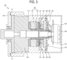
- FIG. 3 is a cross-sectional view of the actuator module shown in FIG. 1 , which is taken along the line 2-2 in FIG. 1 .
- FIG. 3 shows the components of the actuator module 100 that are disposed in a direction transverse to the line 2-2 in the actuator module 100.
- the first housing 110 and the second housing 120 of the actuator module 100 may be coupled to each other to form the sealed structure therein.
- the first housing 110 may surround the motor part 130, the reducer 140, the brake 150, the encoder 160, the controller 170, and the heat dissipation structure 180.
- the components of the actuator module 100 may be disposed inside the sealed structure.
- the actuator module 100 may include the motor part 130 that includes the drive shaft 132 and the drive part 131 for rotating the drive shaft 132.
- the reducer 140 for increasing the torque according to the output of the motor part 130 may be disposed on one side of the drive part 131.
- the brake 150 for suppressing the rotation of the drive shaft 132 may be disposed on the opposite side of the drive part 131.
- the encoder 160 for sensing the operation of the drive shaft 132 may be disposed on one side of the brake 150.
- the partition wall 155 may be disposed between the brake 150 and the encoder 160.
- the controller 170 electrically connected to the motor part 130 to control the motor part 130 may be disposed on one side of the encoder 160.
- the heat dissipation structure 180 may be disposed on one side of the controller 170. The heat dissipation structure 180 may be disposed so as to be spaced apart from the controller 170 by a predetermined distance.
- an airflow path 190 through which an airflow can flow may be formed to extend from the motor part 130 up to the heat dissipation structure 180.
- the airflow path 190 may be a path through which the airflow heated in the motor part 130 flows to the heat dissipation structure 180.
- FIG. 4 is an enlarged partial cross-sectional view showing the airflow path shown in FIG. 3 .
- the airflow path 190 may include one end 191 and the opposite end 192.
- the one end 191 of the airflow path 190 may be opened toward the motor part 130, and the opposite end 192 of the airflow path 190 may be opened toward the heat dissipation structure 180.
- the opposite end 192 of the airflow path 190 may penetrate through the partition wall 155 disposed between the brake 150 and the encoder 160. That is, a through-hole may be formed in the partition wall 155, and the opposite end 192 of the airflow path 190 may include the through-hole of the partition wall 155. As the opposite end 192 of the airflow path 190 penetrates through the partition wall 155, the airflow flowing along the airflow path 190 may flow from the motor part 130 toward the heat dissipation structure 180 without being blocked by the partition wall 155.
- the airflow path 190 may include, as a boundary surface, the inner surface of the first housing 110 and at least a portion of the outer surfaces of the motor part 130, the brake 150, and the partition wall 155. That is, a predetermined boundary surface of the airflow path 190 may be the inner surface of the first housing 110 and at least a portion of the outer surfaces of the motor part 130, the brake 150, and the partition wall 155. The airflow path 190 may be a portion surrounded by the inner surface of the first housing 110 and at least a portion of the outer surfaces of the motor part 130, the brake 150 and the partition wall 155.
- the airflow heated by the heat generated in the motor part 130 may be circulated while passing through the airflow path 190.
- the heated airflow may flow into the airflow path 190 through the one end 191 of the airflow path 190.
- the airflow flowing into the airflow path 190 may pass through the airflow path 190 which includes, as the boundary surface, the inner surface of the first housing 110 and at least a portion of the outer surfaces of the motor part 130, the brake 150 and the partition wall 155.
- the airflow may flow out from the airflow path 190 through the opposite end 192 of the airflow path 190.
- the opposite end 192 may include the through-hole formed in the partition wall 155.
- the airflow flowing out from the airflow path 190 may reach the heat dissipation structure 180 and thereafter may be rapidly cooled.
- An airflow circulation member 135 configured to circulate the airflow located around the motor part 130 is formed in the drive shaft 132 of the actuator module 100.
- the airflow circulation member 135 circulates the airflow located around the drive shaft 132.
- the airflow circulation member 135 may circulate the heated airflow located around the drive shaft 132 to prevent the heated airflow from remaining around the drive shaft 132 for more than a certain period of time.
- the airflow circulation member 135 may be formed to protrude from the drive shaft 132 in a radially outward direction. At least a portion of the airflow circulation member 135 extends so as to be located within the airflow path 190. At least a portion of the airflow circulation member 135 may be located at the one end 191 of the airflow path 190.
- the airflow circulation member 135 may be rotated together with the drive shaft 132 when the drive shaft 132 is rotated.
- the airflow circulation member 135 may circulate the airflow while being rotated together with the drive shaft 132 according to the rotation of the drive shaft 132. At least a portion of the airflow circulation member 135 may allow the heated airflow to pass through the airflow path 190 while being rotated in the airflow path 190.
- FIG. 5 is an exemplary perspective view of the airflow circulation member shown in FIG. 3 .
- the airflow circulation member 135 may be a plurality of fans.
- the plurality of fans may be disposed at an equal interval along the circumference of the drive shaft 132.
- the plurality of fans may extend in a radially outward direction from a rotation axis about which the drive shaft 132 is rotated.
- the plurality of fans may have a width that gradually increases along the radially outward direction from the rotation axis of the drive shaft 132.
- FIG. 6 is another exemplary perspective view of the airflow circulation member shown in FIG. 3 .
- the airflow circulation member 135 may be a plurality of protrusions.
- the plurality of protrusions may have the same shape, and may be disposed at an equal interval along the circumference of the drive shaft 132.
- the plurality of protrusions may generate wind in a direction away from the drive shaft 132 when the drive shaft 132 is rotated.
- Each of the protrusions may have a width that gradually decreases in a direction away from the drive shaft 132.
- Each of the protrusions may be, for example, a prism including a cylinder, or a truncated pyramid including a truncated cone.
- the protrusion when each of the protrusions is a truncated quadrangular pyramid, the protrusion may have a quadrangular cross-section, and the area of the quadrangular cross-section may gradually decrease along a direction away from the drive shaft 132.
- the actuator module 100 can have the sealed structure formed by the housing, thereby protecting the components inside the actuator module 100 from external impact and preventing the inflow of foreign substances. Further, the actuator module 100 according to one embodiment not only can have the sealed structure, but also can effectively dissipate the heat generated inside the actuator module 100 to the outside. The heated airflow can be smoothly circulated in the actuator module 100, thereby dispersing the heat inside the housing of the actuator module 100. Therefore, it is possible to prevent the components of the actuator module 100 from being damaged or from malfunctioning.
Landscapes
- Engineering & Computer Science (AREA)
- Power Engineering (AREA)
- Mechanical Engineering (AREA)
- Robotics (AREA)
- Microelectronics & Electronic Packaging (AREA)
- Physics & Mathematics (AREA)
- General Engineering & Computer Science (AREA)
- Electromagnetism (AREA)
- Thermal Sciences (AREA)
- Connection Of Motors, Electrical Generators, Mechanical Devices, And The Like (AREA)
Description
- The present invention relates to an actuator module including a heat dissipation structure.
- The present invention has been derived from research conducted as part of the Core Technology Development For Energy Demand Management project of the Ministry of Trade, Industry and Energy of Republic of Korea. [Project Identification Number: 1415169323, Research Title: Development and Demonstration of Robot-Based Rapid Automatic Charging System For Electric Automobile]
- An actuator module may have a sealed structure formed by a housing. Components of the actuator module may be located in the sealed structure formed by the housing. The actuator module can protect the components of the actuator module from external impact through the sealed structure of the housing and can prevent foreign substances from entering the components.
- When the actuator module is driven, heat may be generated from some components of the actuator module. For example, heat may be generated from a motor and a controller among the components of the actuator module. The heat generated from the components of the actuator module located inside the housing needs to be dissipated out of the housing.
- The actuator module may be mounted to a predetermined device to provide a driving force for driving the device. The actuator module may have a sealed structure that protects its components from external impact and prevents the inflow of foreign substances. When the actuator module is driven, heat may be generated from the components of the actuator module. Due to the sealed structure, the heat generated from the components of the actuator module is not dissipated to the outside and remains inside the housing. This may reduce the efficiency of dissipating the heat out of the housing.
- If the heat generated from the components of the actuator module is not smoothly dissipated to the outside of the housing, some of the components of the actuator module may be damaged or malfunction due to high temperature, thereby causing problems in the operations of the components. For example, if an electronic circuit board or the like is damaged due to the heat, it may be difficult to operate the actuator module normally. A separate cooling line may be proposed in order to dissipate the heat generated from the components of the actuator module to the outside of the housing. However, such a cooling line increases the size of the actuator module, which may cause difficulties in miniaturization of the actuator module. In addition, such a cooling line is required to separately manage a refrigerant, which may cause difficulties in managing the actuator module by a user.
-
EP 3 348 362 A1 discloses a mechanical joint configured for providing dissipation of heat generated therein, the mechanical joint comprisinga housing containing a motor assembly configured to drive a gear assembly for driving the mechanical joint. The motor assembly is configured to be controlled by a control assembly for controlling rotation of a rotor of the motor assembly. A brake disk of the control assembly is configured to increase air flow within the housing. - The present invention provides an actuator module including a heat dissipation structure.
- Embodiments of the present disclosure solve the aforementioned problems and provide an actuator module that not only can have a sealed structure for protecting the components inside the actuator module but also can effectively dissipate heat generated inside the actuator module to the outside.
- An actuator module according to the present invention is defined in claim 1 and includes a motor part including a drive shaft and a drive part which includes the stator of an electric motor and is configured to rotate the drive shaft, a reducer installed on one axial side of the drive part and configured to increase an output torque according to driving of the motor part, a brake installed on the opposite axial side of the drive part and configured to suppress rotation of the motor part, an encoder installed on the axial side of the brake opposite to the drive part and configured to sense an operation of the drive shaft, a controller installed on the axial side of the encoder opposite to the brake and electrically connected to the motor part to control the motor part, and a first housing configured to surround the motor part, the reducer, the brake, the encoder and the controller. An airflow path through which an airflow can flow in order to dissipate the heat generated inside the actuator module to the outside is formed to extend from the motor part. An airflow circulation member configured to circulate an airflow located around the motor part is formed in the drive shaft at an axial position between the motor part and the brake. The airflow circulation member extends such that at least a portion of the airflow circulation member is located within the airflow path.
- In one embodiment, the actuator module may further include a heat dissipation structure installed on one side of the controller and configured to dissipate heat generated from the motor part. The airflow path may be formed to extend up to the heat dissipation structure.
- In one embodiment, the actuator module may further include a second housing coupled to one side of the first housing. The second housing may form a sealed structure together with the first housing.
- In one embodiment, a flexible sealing member may be disposed between the first housing and the second housing.
- In one embodiment, the heat dissipation structure includes a heat dissipation plate made of a metal material.
- In one embodiment, a gap may be formed between the controller and the heat dissipation structure, and the heat dissipation structure may be attached to an inner surface of the first housing.
- In one embodiment, one end of the airflow path may be opened toward the motor part, and an opposite end of the airflow path may be opened toward the heat dissipation structure.
- In one embodiment, the actuator module may further include a partition wall configured to hold the encoder and disposed between the brake and the encoder. The opposite end of the airflow path may penetrate through the partition wall and may be opened toward the heat dissipation structure.
- In one embodiment, the airflow path may include, as a boundary surface thereof, an inner surface of the first housing and at least a portion of outer surfaces of the motor part, the brake and the partition wall.
- In one embodiment, the airflow heated by the motor part may flow into the airflow path through the one end of the airflow path and may flow out from the airflow path through the opposite end of the airflow path.
- In one embodiment, the airflow circulation member may be formed to protrude from the drive shaft in a radially outward direction when the drive shaft is rotated.
- In one embodiment, the airflow circulation member may be rotated together with the drive shaft.
- In one embodiment, the airflow circulation member may be a plurality of fans, and the plurality of fans may be disposed at an equal interval along a circumference of the drive shaft.
- According to the embodiments of the present invention, the actuator module can have the sealed structure formed by the housing, thereby protecting the components inside the actuator module from external impact and preventing inflow of foreign substances.
- According to the embodiments of the present invention, the actuator module not only can have the sealed structure, but also can effectively dissipate the heat generated inside the actuator module to the outside.
- Further, according to the embodiments of the present invention, the heated airflow can be smoothly circulated in the actuator module, thereby dispersing the heat inside the housing of the actuator module. Therefore, it is possible to prevent the components of the actuator module from being damaged or from malfunctioning.
- The accompanying drawings, which are incorporated in and constitute a part of the specification, illustrate embodiments of the present invention.
-
FIG. 1 is a perspective view of an actuator module according to one embodiment. -
FIG. 2 is an exploded cross-sectional perspective view of the actuator module shown inFIG. 1 , which is taken along line 2-2 inFIG. 1 . -
FIG. 3 is a cross-sectional view of the actuator module shown inFIG. 1 , which is taken along the line 2-2 inFIG. 1 . -
FIG. 4 is an enlarged partial cross-sectional view showing an airflow path shown inFIG. 3 . -
FIG. 5 is an exemplary perspective view of an airflow circulation member shown inFIG. 3 . -
FIG. 6 is another exemplary perspective view of an airflow circulation member shown inFIG. 3 . - Embodiments of the present invention are illustrated for the purpose of explaining the technical idea of the present invention. The scope of rights according to the present invention is not limited to the embodiments presented below or the detailed descriptions of such embodiments.
- An "embodiment" in the present invention is any classification for easily explaining the technical idea of the present invention, and individual embodiments do not need to be mutually exclusive to one another. For example, components disclosed in one embodiment may be applied to and embodied in another embodiment. The components disclosed in one embodiment may be applied and embodied by being modified as far as they do not depart from the scope of the invention, which is defined by the appended claims.
- All technical terms and scientific terms used in the present disclosure include meanings that are commonly understood by those of ordinary skill in the technical field to which the present disclosure pertains unless otherwise defined. All terms used in the present disclosure are selected for the purpose of describing the present invention more clearly, and are not selected to limit the scope of the rights according to the present invention.
- Expressions such as "comprising," "including," "having," and the like used in the present disclosure are to be understood as open-ended terms having the possibility of encompassing other embodiments, unless otherwise mentioned in the phrase or sentence containing such expressions. Further, the terms such as "part," "module," and the like used in the present disclosure mean a unit performing at least one function or operation.
- A "longitudinal direction" of an element throughout the specification may be a direction in which the element extends along one directional axis of the element. In this regard, the one directional axis of the element may mean a direction in which the element extends longer than the other directional axis transverse to the one directional axis.
- Expressions such as "consisting of only an element" and the like used in the present disclosure are to be understood as closed-ended terms excluding the possibility of encompassing another element other than said element.
- Singular expressions described in the present disclosure may encompass plural expressions unless otherwise mentioned, which will also be applied to singular expressions recited in the claims.
- Expressions such as "first," "second," etc. used in the present disclosure are used to separate a plurality of elements from each other, and are not intended to limit an order or importance of the elements.
- The directional terms "one side" used in the present disclosure means any one direction with reference to a center of one element, while the directional terms "opposite side" means a direction opposite to the one side direction. However, this is merely a reference for purposes of explanation for clear understanding of the present invention. The one side and the opposite side may be defined differently depending on where the reference is set.
- Hereinafter, embodiments of the present invention will be described with reference to the accompanying drawings. Like reference numerals in the drawings denote like or corresponding elements. Further, in the following descriptions of the embodiments, redundant descriptions for the same or corresponding elements may be omitted. However, even if the descriptions of the elements are omitted, such elements are not intended to be excluded in any embodiment.
-
FIG. 1 is a perspective view of an actuator module according to one embodiment. - The
actuator module 100 includes afirst housing 110 and may include asecond housing 120 which form the exterior of theactuator module 100. Thefirst housing 110 and thesecond housing 120 may be separated from each other. Thesecond housing 120 may be coupled to one side of the first housing. Thefirst housing 110 and thesecond housing 120 may be coupled to each other to form a sealed structure therein. - The
first housing 110 may be divided into oneend portion 110a and anopposite end portion 110b. The oneend portion 110a and theopposite end portion 110b of thefirst housing 110 may be coupled to each other to form an internal space. Components of theactuator module 100 may be disposed in the internal space. - A
connection member 145 may protrude toward one side of thesecond housing 120. Theconnection member 145 may be connected to a predetermined device. Theconnection member 145 connected to the predetermined device may provide the predetermined device with a driving force for driving the device. -
FIG. 2 is an exploded cross-sectional perspective view of the actuator module shown inFIG. 1 , which is taken along line 2-2 inFIG. 1 . - The internal components of the
actuator module 100 will be described with reference toFIG. 2 . Theactuator module 100 includes amotor part 130 installed in thefirst housing 110. Themotor part 130 includes adrive shaft 132 and adrive part 131 configured to rotate thedrive shaft 132. - The
drive part 131 may convert electrical energy into rotational energy by using a force applied to a conductor in a magnetic field. Thedrive part 131 includes a stator. The stator may include a plurality of stator cores. Thedrive part 131 may include coils that are wound around the stator cores so as to form a rotating magnetic field. When an electric current flows through the coils, thedrive part 131 may rotate thedrive shaft 132 through electrical interaction. - The
drive shaft 132 may be held in thedrive part 131. Thedrive shaft 132 may be held in thedrive part 131 through a bearing. When an electrical current flows through thedrive part 131, thedrive part 131 may generate an electromagnetic field that gives an electromagnetic influence to thedrive shaft 132. Thedrive shaft 132 held in thedrive part 131 may be rotated through electrical interaction with thedrive part 131. Thedrive shaft 132 may rotate theconnection member 145 protruding toward one side of thesecond housing 120. Thedrive shaft 132 may extend from one side to the opposite side in an elongated shape. Thedrive shaft 132 may be a member that transmits the rotational energy of themotor part 130. Thedrive shaft 132 may transmit the output of themotor part 130. - The
actuator module 100 includes areducer 140 installed on one side of thedrive part 131. Thereducer 140 increases the output of themotor part 130. Thereducer 140 increases torque according to the output of themotor part 130. Thereducer 140 may be, for example, at least one of a gear-type reducer, a rolling ball-type reducer, a harmonic drive reducer and a cycloidal reducer. - The gear-type reducer is a widely used reducer, and may use an involute tooth form. The rolling ball-type reducer may be a reducer which performs speed reduction rotation by balls rolling along a guide groove having a shape in which an epicycloid curve and a hypocycloid curve face each other. The harmonic drive reducer may be a reducer which induces speed reduction by transmitting only an elliptical motion component to a flexspline due to an elliptically turning bearing when an elliptical wave generator assembly rotates, and slowly rotating the flexspline such that the flexspline skips an outermost ring gear by one tooth at a time. The cycloidal reducer may be a reducer which achieves speed reduction rotation by fixing pins, and eccentrically rotating a trochoid gear as a planetary gear, and then causing the trochoid gear to only rotate through the pins and the pin holes arranged in the trochoid gear at the same angle.
- The
actuator module 100 includes abrake 150 installed on the opposite side of thedrive part 131. Thebrake 150 may be connected to thedrive shaft 132. Thebrake 150 suppresses rotation of themotor part 130 when an electric power source is not connected to themotor part 130. That is, when an electric power source is not connected to themotor part 130, thebrake 150 may prevent the rotation of themotor part 130 to hinder themotor part 130 from being driven. - The
actuator module 100 includes anencoder 160 installed on one side of thebrake 150. Theencoder 160 senses the operation of themotor part 130. Theencoder 160 may measure a rotation angle of thedrive shaft 132 of themotor part 130. Theencoder 160 may detect the rotation of thedrive shaft 132 by measuring the angle of thedrive shaft 132. Theencoder 160 may output an electrical signal when thedrive shaft 132 is rotated. Theencoder 160 may be, for example, a potentiometer or an optical rotary encoder, but the type of theencoder 160 is not limited thereto. - The
actuator module 100 includes acontroller 170 installed on one side of theencoder 160. Thecontroller 170 may be electrically connected to themotor part 130 to control themotor part 130. Thecontroller 170 may include a motor driver. Thecontroller 170 may receive a user's signal to control the output of themotor part 130. For example, thecontroller 170 may increase the output of themotor part 130 or reduce the output of themotor part 130 according to the user's signal. As the output of themotor part 130 is increased or reduced according to the user's signal, the output of theactuator module 100, i.e., the driving force of theactuator module 100, may be controlled, and the movement of the predetermined device connected to theactuator module 100 may be controlled. - The
actuator module 100 may include apartition wall 155 configured to hold theencoder 160. Theencoder 160 may be mounted on thepartition wall 155. Thepartition wall 155 may be located between thebrake 150 and theencoder 160. Thepartition wall 155 may be connected to thefirst housing 110. Thepartition wall 155 may be connected to thefirst housing 110 to partition one side of thepartition wall 155 and the opposite side of thepartition wall 155. For example, themotor part 130, thereducer 140 and thebrake 150 may be disposed on one side of thepartition wall 155, and theencoder 160, thecontroller 170 and aheat dissipation structure 180 may be disposed on the opposite side of thepartition wall 155. - The
actuator module 100 may include theheat dissipation structure 180 installed on one side of thecontroller 170. Theheat dissipation structure 180 may be installed on one side of thecontroller 170 so as to be spaced apart from thecontroller 170 by a predetermined distance. Theheat dissipation structure 180 may be installed on the inner surface of thefirst housing 110 so as to be spaced apart from thecontroller 170 by a predetermined distance. Theheat dissipation structure 180 may be fixed to the inner surface of theopposite end portion 110b of thefirst housing 110. - The
heat dissipation structure 180 may absorb heat of the inside of thefirst housing 110 and may transfer the heat to the outside of thefirst housing 110. Theheat dissipation structure 180 may be made of a metal material. The metal material may include, but is not limited to, copper (Cu), aluminum (Al) and the like having excellent thermal conductivity. Theheat dissipation structure 180 may include a plurality of heat dissipation plates made of a metal material. The heat dissipation plates may protrude in a direction from the inner surface of theopposite end portion 110b of thefirst housing 110 toward themotor part 130. - A sealing
member 111 may be disposed between the oneend portion 110a of thefirst housing 110 and thesecond housing 120. The sealingmember 111 may be flexible. The sealingmember 111 may be, for example, rubber, but the material of the sealingmember 111 is not limited thereto. - The sealing
member 111 may extend along a contact portion between the oneend portion 110a of thefirst housing 110 and thesecond housing 120. For example, when the contact portion between the oneend portion 110a of thefirst housing 110 and thesecond housing 120 has a circular shape, the sealingmember 111 may also extend in a circular shape. The oneend portion 110a of thefirst housing 110 and thesecond housing 120 may be airtightly coupled to each other through the sealingmember 111. A sealed structure may be formed by thefirst housing 110 and thesecond housing 120. -
FIG. 3 is a cross-sectional view of the actuator module shown inFIG. 1 , which is taken along the line 2-2 inFIG. 1 . -
FIG. 3 shows the components of theactuator module 100 that are disposed in a direction transverse to the line 2-2 in theactuator module 100. - The
first housing 110 and thesecond housing 120 of theactuator module 100 may be coupled to each other to form the sealed structure therein. Thefirst housing 110 may surround themotor part 130, thereducer 140, thebrake 150, theencoder 160, thecontroller 170, and theheat dissipation structure 180. The components of theactuator module 100 may be disposed inside the sealed structure. Theactuator module 100 may include themotor part 130 that includes thedrive shaft 132 and thedrive part 131 for rotating thedrive shaft 132. Thereducer 140 for increasing the torque according to the output of themotor part 130 may be disposed on one side of thedrive part 131. Thebrake 150 for suppressing the rotation of thedrive shaft 132 may be disposed on the opposite side of thedrive part 131. Theencoder 160 for sensing the operation of thedrive shaft 132 may be disposed on one side of thebrake 150. Thepartition wall 155 may be disposed between thebrake 150 and theencoder 160. Thecontroller 170 electrically connected to themotor part 130 to control themotor part 130 may be disposed on one side of theencoder 160. Theheat dissipation structure 180 may be disposed on one side of thecontroller 170. Theheat dissipation structure 180 may be disposed so as to be spaced apart from thecontroller 170 by a predetermined distance. - In the
actuator module 100 according to an embodiment, anairflow path 190 through which an airflow can flow may be formed to extend from themotor part 130 up to theheat dissipation structure 180. Theairflow path 190 may be a path through which the airflow heated in themotor part 130 flows to theheat dissipation structure 180. -
FIG. 4 is an enlarged partial cross-sectional view showing the airflow path shown inFIG. 3 . - The
airflow path 190 may include oneend 191 and theopposite end 192. The oneend 191 of theairflow path 190 may be opened toward themotor part 130, and theopposite end 192 of theairflow path 190 may be opened toward theheat dissipation structure 180. - The
opposite end 192 of theairflow path 190 may penetrate through thepartition wall 155 disposed between thebrake 150 and theencoder 160. That is, a through-hole may be formed in thepartition wall 155, and theopposite end 192 of theairflow path 190 may include the through-hole of thepartition wall 155. As theopposite end 192 of theairflow path 190 penetrates through thepartition wall 155, the airflow flowing along theairflow path 190 may flow from themotor part 130 toward theheat dissipation structure 180 without being blocked by thepartition wall 155. - The
airflow path 190 may include, as a boundary surface, the inner surface of thefirst housing 110 and at least a portion of the outer surfaces of themotor part 130, thebrake 150, and thepartition wall 155. That is, a predetermined boundary surface of theairflow path 190 may be the inner surface of thefirst housing 110 and at least a portion of the outer surfaces of themotor part 130, thebrake 150, and thepartition wall 155. Theairflow path 190 may be a portion surrounded by the inner surface of thefirst housing 110 and at least a portion of the outer surfaces of themotor part 130, thebrake 150 and thepartition wall 155. - The airflow heated by the heat generated in the
motor part 130 may be circulated while passing through theairflow path 190. The heated airflow may flow into theairflow path 190 through the oneend 191 of theairflow path 190. The airflow flowing into theairflow path 190 may pass through theairflow path 190 which includes, as the boundary surface, the inner surface of thefirst housing 110 and at least a portion of the outer surfaces of themotor part 130, thebrake 150 and thepartition wall 155. The airflow may flow out from theairflow path 190 through theopposite end 192 of theairflow path 190. Here, theopposite end 192 may include the through-hole formed in thepartition wall 155. The airflow flowing out from theairflow path 190 may reach theheat dissipation structure 180 and thereafter may be rapidly cooled. - An
airflow circulation member 135 configured to circulate the airflow located around themotor part 130 is formed in thedrive shaft 132 of theactuator module 100. Theairflow circulation member 135 circulates the airflow located around thedrive shaft 132. Theairflow circulation member 135 may circulate the heated airflow located around thedrive shaft 132 to prevent the heated airflow from remaining around thedrive shaft 132 for more than a certain period of time. - The
airflow circulation member 135 may be formed to protrude from thedrive shaft 132 in a radially outward direction. At least a portion of theairflow circulation member 135 extends so as to be located within theairflow path 190. At least a portion of theairflow circulation member 135 may be located at the oneend 191 of theairflow path 190. Theairflow circulation member 135 may be rotated together with thedrive shaft 132 when thedrive shaft 132 is rotated. Theairflow circulation member 135 may circulate the airflow while being rotated together with thedrive shaft 132 according to the rotation of thedrive shaft 132. At least a portion of theairflow circulation member 135 may allow the heated airflow to pass through theairflow path 190 while being rotated in theairflow path 190. -
FIG. 5 is an exemplary perspective view of the airflow circulation member shown inFIG. 3 . - Referring to
FIG. 5 , theairflow circulation member 135 may be a plurality of fans. The plurality of fans may be disposed at an equal interval along the circumference of thedrive shaft 132. The plurality of fans may extend in a radially outward direction from a rotation axis about which thedrive shaft 132 is rotated. The plurality of fans may have a width that gradually increases along the radially outward direction from the rotation axis of thedrive shaft 132. - The plurality of fans may cause the airflow to flow in a direction away from the
drive shaft 132. The plurality of fans may lower the ambient temperature by causing the ambient airflow to flow. The number and shape of the plurality of fans are not limited to those shown inFIG. 5 , and may be varied as necessary. -
FIG. 6 is another exemplary perspective view of the airflow circulation member shown inFIG. 3 . - Referring to
FIG. 6 , theairflow circulation member 135 may be a plurality of protrusions. The plurality of protrusions may have the same shape, and may be disposed at an equal interval along the circumference of thedrive shaft 132. The plurality of protrusions may generate wind in a direction away from thedrive shaft 132 when thedrive shaft 132 is rotated. Each of the protrusions may have a width that gradually decreases in a direction away from thedrive shaft 132. Each of the protrusions may be, for example, a prism including a cylinder, or a truncated pyramid including a truncated cone. For example, when each of the protrusions is a truncated quadrangular pyramid, the protrusion may have a quadrangular cross-section, and the area of the quadrangular cross-section may gradually decrease along a direction away from thedrive shaft 132. - The
actuator module 100 according to one embodiment can have the sealed structure formed by the housing, thereby protecting the components inside theactuator module 100 from external impact and preventing the inflow of foreign substances. Further, theactuator module 100 according to one embodiment not only can have the sealed structure, but also can effectively dissipate the heat generated inside theactuator module 100 to the outside. The heated airflow can be smoothly circulated in theactuator module 100, thereby dispersing the heat inside the housing of theactuator module 100. Therefore, it is possible to prevent the components of theactuator module 100 from being damaged or from malfunctioning. - The technical idea of the present invention has been described heretofore with reference to some embodiments and examples shown in the accompanying drawings. However, it is to be understood that the present invention is not limited to the described embodiments. Modifications and alterations of the described embodiments are contemplated as being alternative forms of the invention as far as they do not depart from the scope of the invention, which is defined by the appended claims.
Claims (13)
- An actuator module (100), comprising:a motor part (130) including a drive shaft (132) and a drive part (131) which includes the stator of an electric motor and is configured to rotate the drive shaft (132) about an axis;a reducer (140) installed on one axial side of the drive part (131) and configured to increase an output torque according to driving of the motor part (130);a brake (150) installed on the opposite axial side of the drive part (131) and configured to suppress rotation of the motor part (130);an encoder (160) installed on the axial side of the brake (150) opposite to the drive part (131) and configured to sense an operation of the drive shaft (132);a controller (170) installed on the axial side of the encoder (160) opposite to the brake (150) and electrically connected to the motor part (130) to control the motor part;a first housing (110) configured to surround the motor part (130), the reducer (140), the brake (150), the encoder (160), and the controller (170),wherein an airflow path (190) through which an airflow can flow in order to dissipate the heat generated inside the actuator module (100) to the outside is formed to extend from the motor part (130); characterized in thatan airflow circulation member (135) configured to circulate an airflow located around the motor part (130) is formed in the drive shaft (132) at an axial position between the motor part (130) and the brake (150),wherein the airflow circulation member (135) extends such that at least a portion of the airflow circulation member (135) is located within the airflow path (190).
- The actuator module of Claim 1, further comprising a heat dissipation structure (180) installed on one axial side of the controller (170) and configured to dissipate heat generated from the motor part (130),
wherein the airflow path (190) is formed to extend up to the heat dissipation structure (180). - The actuator module of Claim 1, further comprising a second housing (120) coupled to one side of the first housing (110),
wherein the second housing (120) forms a sealed structure together with the first housing (110). - The actuator module of Claim 3, wherein a flexible sealing member (111) is disposed between the first housing (110) and the second housing (120).
- The actuator module of Claim 2, wherein the heat dissipation structure (180) includes a heat dissipation plate made of a metal material.
- The actuator module of Claim 5, wherein a gap is formed between the controller (170) and the heat dissipation structure (180), and the heat dissipation structure (180) is attached to an inner surface of the first housing (110).
- The actuator module of Claim 2, wherein one end (191) of the airflow path (190) is opened toward the motor part (130), and an opposite end (192) of the airflow path (190) is opened toward the heat dissipation structure (180).
- The actuator module of Claim 7, further comprising a partition wall (155) configured to hold the encoder (160) and disposed between the brake (150) and the encoder (160),
wherein the opposite end (192) of the airflow path (190) penetrates through the partition wall (155) and is opened toward the heat dissipation structure (180). - The actuator module of Claim 8, wherein the airflow path (190) includes, as a boundary surface thereof, an inner surface of the first housing (110) and at least a portion of outer surfaces of the motor part (130), the brake (150), and the partition wall (155).
- The actuator module of Claim 7, wherein the airflow heated by the motor part (130) flows into the airflow path (190) through the one end (191) of the airflow path and flows out from the airflow path (190) through the opposite end (192) of the airflow path.
- The actuator module of Claim 1, wherein the airflow circulation member (135) is formed to protrude from the drive shaft (132) in a radially outward direction.
- The actuator module of Claim 11, wherein the airflow circulation member (135) is configured to be rotated together with the drive shaft (132) when the drive shaft is rotated.
- The actuator module of Claim 11, wherein the airflow circulation member (135) is a plurality of fans, and the plurality of fans are disposed at an equal interval along a circumference of the drive shaft (132).
Applications Claiming Priority (1)
| Application Number | Priority Date | Filing Date | Title |
|---|---|---|---|
| KR1020200156907A KR102513367B1 (en) | 2020-11-20 | 2020-11-20 | Actuator module |
Publications (2)
| Publication Number | Publication Date |
|---|---|
| EP4007135A1 EP4007135A1 (en) | 2022-06-01 |
| EP4007135B1 true EP4007135B1 (en) | 2025-03-26 |
Family
ID=78617221
Family Applications (1)
| Application Number | Title | Priority Date | Filing Date |
|---|---|---|---|
| EP21207852.1A Active EP4007135B1 (en) | 2020-11-20 | 2021-11-11 | Actuator module |
Country Status (4)
| Country | Link |
|---|---|
| US (1) | US12036671B2 (en) |
| EP (1) | EP4007135B1 (en) |
| KR (1) | KR102513367B1 (en) |
| CN (1) | CN216699669U (en) |
Families Citing this family (3)
| Publication number | Priority date | Publication date | Assignee | Title |
|---|---|---|---|---|
| EP4706157A1 (en) * | 2023-05-03 | 2026-03-11 | Sew-Eurodrive GmbH & Co. KG | Electric motor having an electromagnetically actuatable brake |
| CN116619347A (en) * | 2023-07-06 | 2023-08-22 | 深圳逐际动力科技有限公司 | Actuator, biped, quadruped and quadruped robot, mechanical arm and control method |
| DE102023127750A1 (en) * | 2023-10-11 | 2025-04-17 | Mci (Mirror Controls International) Netherlands B.V. | Actuator for use in a motor vehicle |
Family Cites Families (8)
| Publication number | Priority date | Publication date | Assignee | Title |
|---|---|---|---|---|
| JP5003369B2 (en) * | 2007-09-11 | 2012-08-15 | 株式会社安川電機 | Hollow actuator |
| JP2017094453A (en) * | 2015-11-25 | 2017-06-01 | パナソニックIpマネジメント株式会社 | Electric tool |
| KR102510262B1 (en) * | 2016-02-02 | 2023-03-15 | 엘지이노텍 주식회사 | Motor housing, Motor and Brake apparatus having the same |
| EP3301405A1 (en) * | 2016-09-29 | 2018-04-04 | Siemens Aktiengesellschaft | Verbinden einer motorwelle eines motors mit einem drehgeber |
| US11161258B2 (en) * | 2017-01-16 | 2021-11-02 | Kollmorgen Corporation | Robot arm joint |
| CN107398924B (en) * | 2017-09-20 | 2023-04-21 | 河北工业大学 | Hollow type driving and controlling integrated intelligent modularized joint |
| JP6892080B2 (en) * | 2018-08-09 | 2021-06-18 | 東京ロボティクス株式会社 | Robot arm and robot |
| KR102177405B1 (en) * | 2019-06-07 | 2020-11-12 | 하이젠모터 주식회사 | Driving modules with hollowness |
-
2020
- 2020-11-20 KR KR1020200156907A patent/KR102513367B1/en active Active
-
2021
- 2021-11-11 EP EP21207852.1A patent/EP4007135B1/en active Active
- 2021-11-12 US US17/525,058 patent/US12036671B2/en active Active
- 2021-11-18 CN CN202122834136.0U patent/CN216699669U/en active Active
Also Published As
| Publication number | Publication date |
|---|---|
| KR20220069609A (en) | 2022-05-27 |
| CN216699669U (en) | 2022-06-07 |
| US20220161420A1 (en) | 2022-05-26 |
| KR102513367B1 (en) | 2023-03-24 |
| EP4007135A1 (en) | 2022-06-01 |
| US12036671B2 (en) | 2024-07-16 |
Similar Documents
| Publication | Publication Date | Title |
|---|---|---|
| US12036671B2 (en) | Actuator module with torque output control | |
| US7224094B2 (en) | Magnetic bearing spindle | |
| JP7478206B2 (en) | Power module and power equipment | |
| KR102177405B1 (en) | Driving modules with hollowness | |
| JP6952887B2 (en) | Electric drive system | |
| WO2013008266A1 (en) | Electric motor | |
| DE10141397A1 (en) | Motor driven compressor | |
| CN114448150B (en) | Integrated electric drive system cooling structure and integrated electric drive system | |
| CN112653297B (en) | Motor device | |
| JP7216068B2 (en) | IN-WHEEL ELECTRIC MOTOR WITH INVERTER AND MANUFACTURING METHOD OF SUCH IN-WHEEL ELECTRIC MOTOR | |
| JP6259087B2 (en) | Rotating electric machine | |
| CN113612329A (en) | Axial flux electric machine | |
| WO2011108479A1 (en) | In-wheel motor drive device and design method therefor | |
| US20240151226A1 (en) | Pump device | |
| KR100901751B1 (en) | Housing of the multifunctional integrated motor | |
| JP2007181350A (en) | Motor structure of servo unit for radio control | |
| US12043097B2 (en) | Drive device for a roof component of a vehicle | |
| KR102544771B1 (en) | Rotor assembly and motor including the same | |
| JP7681997B2 (en) | Electric Fluid Pump | |
| CN101090210A (en) | Fan and its inner rotor motor | |
| JP2023035183A (en) | motors and aircraft | |
| US20250239921A1 (en) | Motor unit | |
| CN120902007B (en) | Robot joint module with active heat dissipation function and robot | |
| CN218387142U (en) | Motor, power assembly and vehicle | |
| EP4362286A1 (en) | Electric drive assembly system and vehicle |
Legal Events
| Date | Code | Title | Description |
|---|---|---|---|
| PUAI | Public reference made under article 153(3) epc to a published international application that has entered the european phase |
Free format text: ORIGINAL CODE: 0009012 |
|
| STAA | Information on the status of an ep patent application or granted ep patent |
Free format text: STATUS: REQUEST FOR EXAMINATION WAS MADE |
|
| 17P | Request for examination filed |
Effective date: 20211111 |
|
| AK | Designated contracting states |
Kind code of ref document: A1 Designated state(s): AL AT BE BG CH CY CZ DE DK EE ES FI FR GB GR HR HU IE IS IT LI LT LU LV MC MK MT NL NO PL PT RO RS SE SI SK SM TR |
|
| STAA | Information on the status of an ep patent application or granted ep patent |
Free format text: STATUS: EXAMINATION IS IN PROGRESS |
|
| 17Q | First examination report despatched |
Effective date: 20240807 |
|
| GRAP | Despatch of communication of intention to grant a patent |
Free format text: ORIGINAL CODE: EPIDOSNIGR1 |
|
| STAA | Information on the status of an ep patent application or granted ep patent |
Free format text: STATUS: GRANT OF PATENT IS INTENDED |
|
| INTG | Intention to grant announced |
Effective date: 20241021 |
|
| GRAS | Grant fee paid |
Free format text: ORIGINAL CODE: EPIDOSNIGR3 |
|
| GRAA | (expected) grant |
Free format text: ORIGINAL CODE: 0009210 |
|
| STAA | Information on the status of an ep patent application or granted ep patent |
Free format text: STATUS: THE PATENT HAS BEEN GRANTED |
|
| AK | Designated contracting states |
Kind code of ref document: B1 Designated state(s): AL AT BE BG CH CY CZ DE DK EE ES FI FR GB GR HR HU IE IS IT LI LT LU LV MC MK MT NL NO PL PT RO RS SE SI SK SM TR |
|
| REG | Reference to a national code |
Ref country code: GB Ref legal event code: FG4D |
|
| REG | Reference to a national code |
Ref country code: CH Ref legal event code: EP |
|
| REG | Reference to a national code |
Ref country code: DE Ref legal event code: R096 Ref document number: 602021028068 Country of ref document: DE |
|
| REG | Reference to a national code |
Ref country code: IE Ref legal event code: FG4D |
|
| PG25 | Lapsed in a contracting state [announced via postgrant information from national office to epo] |
Ref country code: RS Free format text: LAPSE BECAUSE OF FAILURE TO SUBMIT A TRANSLATION OF THE DESCRIPTION OR TO PAY THE FEE WITHIN THE PRESCRIBED TIME-LIMIT Effective date: 20250626 |
|
| PG25 | Lapsed in a contracting state [announced via postgrant information from national office to epo] |
Ref country code: FI Free format text: LAPSE BECAUSE OF FAILURE TO SUBMIT A TRANSLATION OF THE DESCRIPTION OR TO PAY THE FEE WITHIN THE PRESCRIBED TIME-LIMIT Effective date: 20250326 |
|
| REG | Reference to a national code |
Ref country code: LT Ref legal event code: MG9D |
|
| PG25 | Lapsed in a contracting state [announced via postgrant information from national office to epo] |
Ref country code: NO Free format text: LAPSE BECAUSE OF FAILURE TO SUBMIT A TRANSLATION OF THE DESCRIPTION OR TO PAY THE FEE WITHIN THE PRESCRIBED TIME-LIMIT Effective date: 20250626 |
|
| PG25 | Lapsed in a contracting state [announced via postgrant information from national office to epo] |
Ref country code: HR Free format text: LAPSE BECAUSE OF FAILURE TO SUBMIT A TRANSLATION OF THE DESCRIPTION OR TO PAY THE FEE WITHIN THE PRESCRIBED TIME-LIMIT Effective date: 20250326 |
|
| PG25 | Lapsed in a contracting state [announced via postgrant information from national office to epo] |
Ref country code: LV Free format text: LAPSE BECAUSE OF FAILURE TO SUBMIT A TRANSLATION OF THE DESCRIPTION OR TO PAY THE FEE WITHIN THE PRESCRIBED TIME-LIMIT Effective date: 20250326 |
|
| PG25 | Lapsed in a contracting state [announced via postgrant information from national office to epo] |
Ref country code: GR Free format text: LAPSE BECAUSE OF FAILURE TO SUBMIT A TRANSLATION OF THE DESCRIPTION OR TO PAY THE FEE WITHIN THE PRESCRIBED TIME-LIMIT Effective date: 20250627 Ref country code: BG Free format text: LAPSE BECAUSE OF FAILURE TO SUBMIT A TRANSLATION OF THE DESCRIPTION OR TO PAY THE FEE WITHIN THE PRESCRIBED TIME-LIMIT Effective date: 20250326 |
|
| REG | Reference to a national code |
Ref country code: NL Ref legal event code: MP Effective date: 20250326 |
|
| PG25 | Lapsed in a contracting state [announced via postgrant information from national office to epo] |
Ref country code: NL Free format text: LAPSE BECAUSE OF FAILURE TO SUBMIT A TRANSLATION OF THE DESCRIPTION OR TO PAY THE FEE WITHIN THE PRESCRIBED TIME-LIMIT Effective date: 20250326 |
|
| PG25 | Lapsed in a contracting state [announced via postgrant information from national office to epo] |
Ref country code: SE Free format text: LAPSE BECAUSE OF FAILURE TO SUBMIT A TRANSLATION OF THE DESCRIPTION OR TO PAY THE FEE WITHIN THE PRESCRIBED TIME-LIMIT Effective date: 20250326 |
|
| REG | Reference to a national code |
Ref country code: AT Ref legal event code: MK05 Ref document number: 1779956 Country of ref document: AT Kind code of ref document: T Effective date: 20250326 |
|
| PG25 | Lapsed in a contracting state [announced via postgrant information from national office to epo] |
Ref country code: SM Free format text: LAPSE BECAUSE OF FAILURE TO SUBMIT A TRANSLATION OF THE DESCRIPTION OR TO PAY THE FEE WITHIN THE PRESCRIBED TIME-LIMIT Effective date: 20250326 |
|
| PG25 | Lapsed in a contracting state [announced via postgrant information from national office to epo] |
Ref country code: PT Free format text: LAPSE BECAUSE OF FAILURE TO SUBMIT A TRANSLATION OF THE DESCRIPTION OR TO PAY THE FEE WITHIN THE PRESCRIBED TIME-LIMIT Effective date: 20250728 Ref country code: ES Free format text: LAPSE BECAUSE OF FAILURE TO SUBMIT A TRANSLATION OF THE DESCRIPTION OR TO PAY THE FEE WITHIN THE PRESCRIBED TIME-LIMIT Effective date: 20250326 |
|
| PG25 | Lapsed in a contracting state [announced via postgrant information from national office to epo] |
Ref country code: IT Free format text: LAPSE BECAUSE OF FAILURE TO SUBMIT A TRANSLATION OF THE DESCRIPTION OR TO PAY THE FEE WITHIN THE PRESCRIBED TIME-LIMIT Effective date: 20250326 Ref country code: PL Free format text: LAPSE BECAUSE OF FAILURE TO SUBMIT A TRANSLATION OF THE DESCRIPTION OR TO PAY THE FEE WITHIN THE PRESCRIBED TIME-LIMIT Effective date: 20250326 |
|
| PG25 | Lapsed in a contracting state [announced via postgrant information from national office to epo] |
Ref country code: AT Free format text: LAPSE BECAUSE OF FAILURE TO SUBMIT A TRANSLATION OF THE DESCRIPTION OR TO PAY THE FEE WITHIN THE PRESCRIBED TIME-LIMIT Effective date: 20250326 |
|
| PG25 | Lapsed in a contracting state [announced via postgrant information from national office to epo] |
Ref country code: EE Free format text: LAPSE BECAUSE OF FAILURE TO SUBMIT A TRANSLATION OF THE DESCRIPTION OR TO PAY THE FEE WITHIN THE PRESCRIBED TIME-LIMIT Effective date: 20250326 |
|
| PG25 | Lapsed in a contracting state [announced via postgrant information from national office to epo] |
Ref country code: RO Free format text: LAPSE BECAUSE OF FAILURE TO SUBMIT A TRANSLATION OF THE DESCRIPTION OR TO PAY THE FEE WITHIN THE PRESCRIBED TIME-LIMIT Effective date: 20250326 |
|
| PG25 | Lapsed in a contracting state [announced via postgrant information from national office to epo] |
Ref country code: SK Free format text: LAPSE BECAUSE OF FAILURE TO SUBMIT A TRANSLATION OF THE DESCRIPTION OR TO PAY THE FEE WITHIN THE PRESCRIBED TIME-LIMIT Effective date: 20250326 |
|
| PG25 | Lapsed in a contracting state [announced via postgrant information from national office to epo] |
Ref country code: IS Free format text: LAPSE BECAUSE OF FAILURE TO SUBMIT A TRANSLATION OF THE DESCRIPTION OR TO PAY THE FEE WITHIN THE PRESCRIBED TIME-LIMIT Effective date: 20250726 |
|
| REG | Reference to a national code |
Ref country code: DE Ref legal event code: R097 Ref document number: 602021028068 Country of ref document: DE |
|
| PGFP | Annual fee paid to national office [announced via postgrant information from national office to epo] |
Ref country code: DE Payment date: 20251015 Year of fee payment: 5 |
|
| PG25 | Lapsed in a contracting state [announced via postgrant information from national office to epo] |
Ref country code: DK Free format text: LAPSE BECAUSE OF FAILURE TO SUBMIT A TRANSLATION OF THE DESCRIPTION OR TO PAY THE FEE WITHIN THE PRESCRIBED TIME-LIMIT Effective date: 20250326 |
|
| PG25 | Lapsed in a contracting state [announced via postgrant information from national office to epo] |
Ref country code: CZ Free format text: LAPSE BECAUSE OF FAILURE TO SUBMIT A TRANSLATION OF THE DESCRIPTION OR TO PAY THE FEE WITHIN THE PRESCRIBED TIME-LIMIT Effective date: 20250326 |
|
| PLBE | No opposition filed within time limit |
Free format text: ORIGINAL CODE: 0009261 |
|
| STAA | Information on the status of an ep patent application or granted ep patent |
Free format text: STATUS: NO OPPOSITION FILED WITHIN TIME LIMIT |
|
| REG | Reference to a national code |
Ref country code: CH Ref legal event code: L10 Free format text: ST27 STATUS EVENT CODE: U-0-0-L10-L00 (AS PROVIDED BY THE NATIONAL OFFICE) Effective date: 20260211 |
|
| 26N | No opposition filed |
Effective date: 20260105 |