EP4007085A1 - Cable assembly and vehicle charging system - Google Patents
Cable assembly and vehicle charging system Download PDFInfo
- Publication number
- EP4007085A1 EP4007085A1 EP20847336.3A EP20847336A EP4007085A1 EP 4007085 A1 EP4007085 A1 EP 4007085A1 EP 20847336 A EP20847336 A EP 20847336A EP 4007085 A1 EP4007085 A1 EP 4007085A1
- Authority
- EP
- European Patent Office
- Prior art keywords
- pin
- hole
- charging
- resistor
- discharging
- Prior art date
- Legal status (The legal status is an assumption and is not a legal conclusion. Google has not performed a legal analysis and makes no representation as to the accuracy of the status listed.)
- Granted
Links
Images



Classifications
-
- B—PERFORMING OPERATIONS; TRANSPORTING
- B60—VEHICLES IN GENERAL
- B60L—PROPULSION OF ELECTRICALLY-PROPELLED VEHICLES; SUPPLYING ELECTRIC POWER FOR AUXILIARY EQUIPMENT OF ELECTRICALLY-PROPELLED VEHICLES; ELECTRODYNAMIC BRAKE SYSTEMS FOR VEHICLES IN GENERAL; MAGNETIC SUSPENSION OR LEVITATION FOR VEHICLES; MONITORING OPERATING VARIABLES OF ELECTRICALLY-PROPELLED VEHICLES; ELECTRIC SAFETY DEVICES FOR ELECTRICALLY-PROPELLED VEHICLES
- B60L53/00—Methods of charging batteries, specially adapted for electric vehicles; Charging stations or on-board charging equipment therefor; Exchange of energy storage elements in electric vehicles
- B60L53/10—Methods of charging batteries, specially adapted for electric vehicles; Charging stations or on-board charging equipment therefor; Exchange of energy storage elements in electric vehicles characterised by the energy transfer between the charging station and the vehicle
- B60L53/14—Conductive energy transfer
- B60L53/18—Cables specially adapted for charging electric vehicles
-
- B—PERFORMING OPERATIONS; TRANSPORTING
- B60—VEHICLES IN GENERAL
- B60L—PROPULSION OF ELECTRICALLY-PROPELLED VEHICLES; SUPPLYING ELECTRIC POWER FOR AUXILIARY EQUIPMENT OF ELECTRICALLY-PROPELLED VEHICLES; ELECTRODYNAMIC BRAKE SYSTEMS FOR VEHICLES IN GENERAL; MAGNETIC SUSPENSION OR LEVITATION FOR VEHICLES; MONITORING OPERATING VARIABLES OF ELECTRICALLY-PROPELLED VEHICLES; ELECTRIC SAFETY DEVICES FOR ELECTRICALLY-PROPELLED VEHICLES
- B60L53/00—Methods of charging batteries, specially adapted for electric vehicles; Charging stations or on-board charging equipment therefor; Exchange of energy storage elements in electric vehicles
- B60L53/10—Methods of charging batteries, specially adapted for electric vehicles; Charging stations or on-board charging equipment therefor; Exchange of energy storage elements in electric vehicles characterised by the energy transfer between the charging station and the vehicle
- B60L53/11—DC charging controlled by the charging station, e.g. mode 4
-
- B—PERFORMING OPERATIONS; TRANSPORTING
- B60—VEHICLES IN GENERAL
- B60L—PROPULSION OF ELECTRICALLY-PROPELLED VEHICLES; SUPPLYING ELECTRIC POWER FOR AUXILIARY EQUIPMENT OF ELECTRICALLY-PROPELLED VEHICLES; ELECTRODYNAMIC BRAKE SYSTEMS FOR VEHICLES IN GENERAL; MAGNETIC SUSPENSION OR LEVITATION FOR VEHICLES; MONITORING OPERATING VARIABLES OF ELECTRICALLY-PROPELLED VEHICLES; ELECTRIC SAFETY DEVICES FOR ELECTRICALLY-PROPELLED VEHICLES
- B60L53/00—Methods of charging batteries, specially adapted for electric vehicles; Charging stations or on-board charging equipment therefor; Exchange of energy storage elements in electric vehicles
- B60L53/10—Methods of charging batteries, specially adapted for electric vehicles; Charging stations or on-board charging equipment therefor; Exchange of energy storage elements in electric vehicles characterised by the energy transfer between the charging station and the vehicle
- B60L53/14—Conductive energy transfer
- B60L53/16—Connectors, e.g. plugs or sockets, specially adapted for charging electric vehicles
-
- B—PERFORMING OPERATIONS; TRANSPORTING
- B60—VEHICLES IN GENERAL
- B60L—PROPULSION OF ELECTRICALLY-PROPELLED VEHICLES; SUPPLYING ELECTRIC POWER FOR AUXILIARY EQUIPMENT OF ELECTRICALLY-PROPELLED VEHICLES; ELECTRODYNAMIC BRAKE SYSTEMS FOR VEHICLES IN GENERAL; MAGNETIC SUSPENSION OR LEVITATION FOR VEHICLES; MONITORING OPERATING VARIABLES OF ELECTRICALLY-PROPELLED VEHICLES; ELECTRIC SAFETY DEVICES FOR ELECTRICALLY-PROPELLED VEHICLES
- B60L53/00—Methods of charging batteries, specially adapted for electric vehicles; Charging stations or on-board charging equipment therefor; Exchange of energy storage elements in electric vehicles
- B60L53/60—Monitoring or controlling charging stations
- B60L53/66—Data transfer between charging stations and vehicles
-
- H—ELECTRICITY
- H01—ELECTRIC ELEMENTS
- H01R—ELECTRICALLY-CONDUCTIVE CONNECTIONS; STRUCTURAL ASSOCIATIONS OF A PLURALITY OF MUTUALLY-INSULATED ELECTRICAL CONNECTING ELEMENTS; COUPLING DEVICES; CURRENT COLLECTORS
- H01R13/00—Details of coupling devices of the kinds covered by groups H01R12/70 or H01R24/00 - H01R33/00
- H01R13/64—Means for preventing incorrect coupling
-
- H—ELECTRICITY
- H01—ELECTRIC ELEMENTS
- H01R—ELECTRICALLY-CONDUCTIVE CONNECTIONS; STRUCTURAL ASSOCIATIONS OF A PLURALITY OF MUTUALLY-INSULATED ELECTRICAL CONNECTING ELEMENTS; COUPLING DEVICES; CURRENT COLLECTORS
- H01R13/00—Details of coupling devices of the kinds covered by groups H01R12/70 or H01R24/00 - H01R33/00
- H01R13/64—Means for preventing incorrect coupling
- H01R13/642—Means for preventing incorrect coupling by position or shape of contact members
-
- H—ELECTRICITY
- H01—ELECTRIC ELEMENTS
- H01R—ELECTRICALLY-CONDUCTIVE CONNECTIONS; STRUCTURAL ASSOCIATIONS OF A PLURALITY OF MUTUALLY-INSULATED ELECTRICAL CONNECTING ELEMENTS; COUPLING DEVICES; CURRENT COLLECTORS
- H01R13/00—Details of coupling devices of the kinds covered by groups H01R12/70 or H01R24/00 - H01R33/00
- H01R13/66—Structural association with built-in electrical component
- H01R13/6608—Structural association with built-in electrical component with built-in single component
- H01R13/6616—Structural association with built-in electrical component with built-in single component with resistor
-
- H—ELECTRICITY
- H01—ELECTRIC ELEMENTS
- H01R—ELECTRICALLY-CONDUCTIVE CONNECTIONS; STRUCTURAL ASSOCIATIONS OF A PLURALITY OF MUTUALLY-INSULATED ELECTRICAL CONNECTING ELEMENTS; COUPLING DEVICES; CURRENT COLLECTORS
- H01R13/00—Details of coupling devices of the kinds covered by groups H01R12/70 or H01R24/00 - H01R33/00
- H01R13/66—Structural association with built-in electrical component
- H01R13/665—Structural association with built-in electrical component with built-in electronic circuit
-
- H—ELECTRICITY
- H01—ELECTRIC ELEMENTS
- H01R—ELECTRICALLY-CONDUCTIVE CONNECTIONS; STRUCTURAL ASSOCIATIONS OF A PLURALITY OF MUTUALLY-INSULATED ELECTRICAL CONNECTING ELEMENTS; COUPLING DEVICES; CURRENT COLLECTORS
- H01R13/00—Details of coupling devices of the kinds covered by groups H01R12/70 or H01R24/00 - H01R33/00
- H01R13/66—Structural association with built-in electrical component
- H01R13/70—Structural association with built-in electrical component with built-in switch
-
- H—ELECTRICITY
- H01—ELECTRIC ELEMENTS
- H01R—ELECTRICALLY-CONDUCTIVE CONNECTIONS; STRUCTURAL ASSOCIATIONS OF A PLURALITY OF MUTUALLY-INSULATED ELECTRICAL CONNECTING ELEMENTS; COUPLING DEVICES; CURRENT COLLECTORS
- H01R24/00—Two-part coupling devices, or either of their cooperating parts, characterised by their overall structure
- H01R24/28—Coupling parts carrying pins, blades or analogous contacts and secured only to wire or cable
- H01R24/30—Coupling parts carrying pins, blades or analogous contacts and secured only to wire or cable with additional earth or shield contacts
-
- H—ELECTRICITY
- H02—GENERATION; CONVERSION OR DISTRIBUTION OF ELECTRIC POWER
- H02J—ELECTRIC POWER NETWORKS; CIRCUIT ARRANGEMENTS OR SYSTEMS FOR SUPPLYING OR DISTRIBUTING ELECTRIC POWER; SYSTEMS FOR STORING ELECTRIC ENERGY
- H02J7/00—Circuit arrangements for charging or discharging batteries or for supplying loads from batteries
- H02J7/34—Parallel operation in networks using both storage and other DC sources, e.g. providing buffering
- H02J7/342—The other DC source being a battery actively interacting with the first one, i.e. battery to battery charging
-
- H—ELECTRICITY
- H02—GENERATION; CONVERSION OR DISTRIBUTION OF ELECTRIC POWER
- H02J—ELECTRIC POWER NETWORKS; CIRCUIT ARRANGEMENTS OR SYSTEMS FOR SUPPLYING OR DISTRIBUTING ELECTRIC POWER; SYSTEMS FOR STORING ELECTRIC ENERGY
- H02J7/00—Circuit arrangements for charging or discharging batteries or for supplying loads from batteries
- H02J7/40—Circuit arrangements for charging or discharging batteries or for supplying loads from batteries characterised by the exchange of charge or discharge related data
- H02J7/47—Arrangements for checking compatibility or authentication between one component, e.g. a battery or a battery charger, and another component, e.g. a power source
-
- H—ELECTRICITY
- H02—GENERATION; CONVERSION OR DISTRIBUTION OF ELECTRIC POWER
- H02J—ELECTRIC POWER NETWORKS; CIRCUIT ARRANGEMENTS OR SYSTEMS FOR SUPPLYING OR DISTRIBUTING ELECTRIC POWER; SYSTEMS FOR STORING ELECTRIC ENERGY
- H02J7/00—Circuit arrangements for charging or discharging batteries or for supplying loads from batteries
- H02J7/70—Circuit arrangements for charging or discharging batteries or for supplying loads from batteries characterised by the mechanical construction
- H02J7/751—Circuit arrangements for charging or discharging batteries or for supplying loads from batteries characterised by the mechanical construction concerning the insertion or the connection of the batteries
-
- H—ELECTRICITY
- H02—GENERATION; CONVERSION OR DISTRIBUTION OF ELECTRIC POWER
- H02J—ELECTRIC POWER NETWORKS; CIRCUIT ARRANGEMENTS OR SYSTEMS FOR SUPPLYING OR DISTRIBUTING ELECTRIC POWER; SYSTEMS FOR STORING ELECTRIC ENERGY
- H02J7/00—Circuit arrangements for charging or discharging batteries or for supplying loads from batteries
- H02J7/865—Battery or charger load switching, e.g. concurrent charging and load supply
-
- H—ELECTRICITY
- H01—ELECTRIC ELEMENTS
- H01R—ELECTRICALLY-CONDUCTIVE CONNECTIONS; STRUCTURAL ASSOCIATIONS OF A PLURALITY OF MUTUALLY-INSULATED ELECTRICAL CONNECTING ELEMENTS; COUPLING DEVICES; CURRENT COLLECTORS
- H01R2107/00—Four or more poles
-
- H—ELECTRICITY
- H01—ELECTRIC ELEMENTS
- H01R—ELECTRICALLY-CONDUCTIVE CONNECTIONS; STRUCTURAL ASSOCIATIONS OF A PLURALITY OF MUTUALLY-INSULATED ELECTRICAL CONNECTING ELEMENTS; COUPLING DEVICES; CURRENT COLLECTORS
- H01R2201/00—Connectors or connections adapted for particular applications
- H01R2201/26—Connectors or connections adapted for particular applications for vehicles
-
- H—ELECTRICITY
- H01—ELECTRIC ELEMENTS
- H01R—ELECTRICALLY-CONDUCTIVE CONNECTIONS; STRUCTURAL ASSOCIATIONS OF A PLURALITY OF MUTUALLY-INSULATED ELECTRICAL CONNECTING ELEMENTS; COUPLING DEVICES; CURRENT COLLECTORS
- H01R31/00—Coupling parts supported only by co-operation with counterpart
- H01R31/06—Intermediate parts for linking two coupling parts, e.g. adapter
- H01R31/065—Intermediate parts for linking two coupling parts, e.g. adapter with built-in electric apparatus
-
- Y—GENERAL TAGGING OF NEW TECHNOLOGICAL DEVELOPMENTS; GENERAL TAGGING OF CROSS-SECTIONAL TECHNOLOGIES SPANNING OVER SEVERAL SECTIONS OF THE IPC; TECHNICAL SUBJECTS COVERED BY FORMER USPC CROSS-REFERENCE ART COLLECTIONS [XRACs] AND DIGESTS
- Y02—TECHNOLOGIES OR APPLICATIONS FOR MITIGATION OR ADAPTATION AGAINST CLIMATE CHANGE
- Y02T—CLIMATE CHANGE MITIGATION TECHNOLOGIES RELATED TO TRANSPORTATION
- Y02T10/00—Road transport of goods or passengers
- Y02T10/60—Other road transportation technologies with climate change mitigation effect
- Y02T10/70—Energy storage systems for electromobility, e.g. batteries
-
- Y—GENERAL TAGGING OF NEW TECHNOLOGICAL DEVELOPMENTS; GENERAL TAGGING OF CROSS-SECTIONAL TECHNOLOGIES SPANNING OVER SEVERAL SECTIONS OF THE IPC; TECHNICAL SUBJECTS COVERED BY FORMER USPC CROSS-REFERENCE ART COLLECTIONS [XRACs] AND DIGESTS
- Y02—TECHNOLOGIES OR APPLICATIONS FOR MITIGATION OR ADAPTATION AGAINST CLIMATE CHANGE
- Y02T—CLIMATE CHANGE MITIGATION TECHNOLOGIES RELATED TO TRANSPORTATION
- Y02T10/00—Road transport of goods or passengers
- Y02T10/60—Other road transportation technologies with climate change mitigation effect
- Y02T10/7072—Electromobility specific charging systems or methods for batteries, ultracapacitors, supercapacitors or double-layer capacitors
-
- Y—GENERAL TAGGING OF NEW TECHNOLOGICAL DEVELOPMENTS; GENERAL TAGGING OF CROSS-SECTIONAL TECHNOLOGIES SPANNING OVER SEVERAL SECTIONS OF THE IPC; TECHNICAL SUBJECTS COVERED BY FORMER USPC CROSS-REFERENCE ART COLLECTIONS [XRACs] AND DIGESTS
- Y02—TECHNOLOGIES OR APPLICATIONS FOR MITIGATION OR ADAPTATION AGAINST CLIMATE CHANGE
- Y02T—CLIMATE CHANGE MITIGATION TECHNOLOGIES RELATED TO TRANSPORTATION
- Y02T90/00—Enabling technologies or technologies with a potential or indirect contribution to GHG emissions mitigation
- Y02T90/10—Technologies relating to charging of electric vehicles
- Y02T90/14—Plug-in electric vehicles
Definitions
- the present disclosure relates to the technical field of vehicles, and in particular, to a cable assembly and a vehicle charging system.
- a dedicated DC charging station (charging cabinet) can achieve quick charging for batteries of the electric vehicles.
- a connection mode thereof is shown in FIG. 1 .
- the DC charging stations are generally fixed and immovable and have a limited quantity, and therefore cannot satisfy charging requirements of the electric vehicles.
- An objective of the present disclosure is to at least resolve one of the technical problems in the related art to some extent.
- the present disclosure is intended to provide a cable assembly.
- the cable assembly can achieve V2V DC charging and has desirable generalization performance.
- the present disclosure is further intended to provide a vehicle charging system.
- an embodiment of a first aspect of the present disclosure provides a cable assembly.
- the cable assembly includes: a power supply plug, adapted to a discharging outlet of a discharging vehicle; a charging plug, adapted to a charging outlet of a to-be-charged vehicle; and a cable, connected between the power supply plug and the charging plug.
- the power supply plug and the charging plug are directly connected to the corresponding vehicle outlets and are removable connection devices, can achieve V2V DC charging, and have more desirable generalization performance compared with charging by using a charging cabinet.
- a second aspect of the present disclosure provides a vehicle charging system.
- the vehicle charging system includes: the cable assembly in the above embodiment; a discharging vehicle, where a discharging outlet is disposed on the discharging vehicle; a to-be-charged vehicle, where a charging outlet is disposed on the to-be-charged vehicle.
- the discharging outlet is adaptively connected to the power supply plug, and the charging outlet is adaptively connected to the charging plug.
- the vehicle charging system in this embodiment of the present disclosure realizes the charging and discharging connection between the discharging vehicle and the to-be-charged vehicle by using cable assembly, can realize V2V DC charging, and has more desirable generalization performance compared with charging connection with a charging cabinet.
- FIG. 2 is a schematic structural diagram of a cable assembly according to an embodiment of the present disclosure.
- a cable assembly 100 includes a power supply plug 110, a charging plug 120, and a cable 130.
- the power supply plug 110 is adapted to a discharging outlet 210 of a discharging vehicle 200
- the charging plug 120 is adapted to a charging outlet 310 of a to-be-charged vehicle 300.
- the cable 130 is connected between the power supply plug 110 and the charging plug 120.
- the to-be-charged vehicle 300 when the to-be-charged vehicle 300 is required to be charged, only the power supply plug 110 is required to be adaptively connected to the discharging outlet 210 of the discharging vehicle 200 and the charging plug 120 is required to be adaptively connected to the charging outlet 310 of the to-be-charged vehicle 300.
- the charging plug 120 is required to be adaptively connected to the charging outlet 310 of the to-be-charged vehicle 300.
- electric energy can be transmitted from the discharging vehicle 200 to the to-be-charged vehicle 300 through the cable 130. That is to say, the charging of the to-be-charged vehicle 300 by the discharging vehicle 200 is realized.
- the operation is simple and easy.
- the cable 130 is composed of a connecting harness.
- the connecting harness includes a DC+ line, a DC-line, a PE line, a CANH line, a CANL line, an A+ line, and an A- line.
- the power supply plug 110 and the charging plug 120 each include 8 pins.
- the power supply plug 110 includes a DC+ pin, a DC- pin, a PE pin, a CANH pin, a CANL pin, an A+ pin, an A- pin, and a CC1 pin.
- the charging plug 120 includes a DC+ pin, a DC- pin, a PE pin, a CANH pin, a CANL pin, an A+ pin, an A- pin, and a CC2 pin.
- the DC+ pin, the DC- pin, the PE pin, the CANH pin, the CANL pin, the A+ pin, and the A- pin of each of the power supply plug 110 and the charging plug 120 are respectively correspondingly connected to the DC+ line, the DC- line, the PE line, the CANH line, the CANL line, the A+ line, and the A- line.
- the power supply plug 110 and the charging plug 120 each have 8 pins disposed thereon, and 7 of the pins are the same, and are respectively correspondingly connected to the 7 lines of the connecting harness of the cable 130. The only difference lies in the one different pin.
- the power supply plug 110 includes a resistor R2, a resistor R3, and a switch S.
- One end of the resistor R3 is connected to the PE pin of the power supply plug 110, an other end of the resistor R3 is connected to one end of the resistor R2, and an other end of the resistor R2 is connected to the CC1 pin of the power supply plug 110.
- the switch S is connected in parallel to the resistor R2.
- the charging plug 120 includes a resistor R5'. One end of the resistor R5' is connected to the PE pin of the charging plug 120, and an other end of the resistor R5' is connected to the CC2 pin of the charging plug 120.
- the power supply plug 110 and the charging plug 120 cannot be transposed. That is to say, in order to realize the charging of the to-be-charged vehicle 300 by the discharging vehicle 200, the power supply plug 110 is allowed to be connected to only the discharging outlet 210, and the charging plug 120 is allowed to be connected to only the charging outlet 310.
- the configurations of the pins of the power supply plug 110 and the charging plug 120 are different.
- a power supply identifier may be disposed on the power supply plug 110, and/or a charging identifier may be disposed on the charging plug 120. That is to say, appearances of the power supply plug 110 and/or the charging plug 120 are marked differently obviously, for example, by using identifiers of different colors, different texts, or the like.
- the power supply plug 110 and the charging plug 120 have a same structure.
- the power supply plug 110 and the charging plug 120 each include 9 pins: a DC+ pin, a DC- pin, a PE pin, a CANH pin, a CANL pin, an A+ pin, an A- pin, a CC1 pin, and a CC2 pin.
- the DC+ pin, the DC- pin, the PE pin, the CANH pin, the CANL pin, the A+ pin, and the A- pin are respectively correspondingly connected to the DC+ line, the DC- line, the PE line, the CANH line, the CANL line, the A+ line and the A- line.
- the power supply plug 110 and the charging plug 120 each have 9 pins disposed thereon, and the 9 pins are the same. 7 of the pins are respectively correspondingly connected to the 7 lines of the connecting harness of the cable 130.
- the power supply plug 110 includes a resistor R2, a resistor R3, a switch S, and a resistor R5.
- One end of the resistor R3 is connected to the PE pin of the power supply plug 110, an other end of the resistor R3 is connected to one end of the resistor R2, and an other end of the resistor R2 is connected to the CC1 pin of the power supply plug.
- the switch S is connected in parallel to the resistor R2.
- One end of the resistor R5 is connected to the PE pin of the power supply plug 110, and an other end of the resistor R5 is connected to the CC2 pin of the power supply plug 110.
- the charging plug 120 includes a resistor R2', a resistor R3', a switch S', and a resistor R5'. Connection modes thereof are same as the connection modes of the components of the power supply plug 110.
- the power supply plug 110 and the charging plug 120 can be transposed. That is to say, the power supply plug 110 may be connected to the discharging outlet 210 or the charging outlet 310. The same is true for the charging plug 120. In this way, connection errors can be avoided.
- the switch S when the pin of the power supply plug 110 is inserted into the discharging outlet 210 or removed from the discharging outlet 210, the switch S may be opened by manual operation.
- a button may be disposed on the power supply plug 110. When the button is pressed, the switch S is opened. At this time, the pins of the power supply plug 110 may be inserted into the discharging outlet 210, or the pins of the power supply plug 110 may be removed from the discharging outlet 210.
- the button is released to close the switch S.
- the discharging outlet 210 and the charging outlet 310 each include a DC+ hole, a DC- hole, a PE hole, a CANH hole, a CANL hole, an A+ hole, an A- hole, a CC1 hole, and a CC2 hole.
- the power supply plug 110 and the charging plug 120 each include 8 pins
- the DC+ hole, the DC- hole, the PE hole, the CANH hole, the CANL hole, the A+ hole, the A- hole, and the CC1 hole of the discharging outlet 210 are respectively correspondingly connected to the DC+ pin, the DC- plug, the PE pin, the CANH pin, the CANL pin, the A+ pin, the A- pin, and the CC1 pin of the power supply plug 110, and the CC2 hole of the discharging outlet 210 is idle.
- the DC+ hole, the DC- hole, the PE hole, the CANH hole, the CANL hole, the A+ hole, the A- hole, and the CC2 hole of the charging outlet 310 are respectively correspondingly connected to the DC+ pin, the DC- plug, the PE pin, the CANH pin, the CANL pin, the A+ pin, the A- pin, and the CC2 pin of the charging plug 120, and the CC1 hole of the charging outlet 310 is idle.
- the power supply plug 110 and the charging plug 120 each include 9 pins
- the DC+ hole, the DC- hole, the PE hole, the CANH hole, the CANL hole, the A+ hole, the A- hole, the CC1 hole, and the CC2 hole of the discharging outlet 210 are respectively correspondingly connected to the DC+ pin, the DC- pin, the PE pin, the CANH pin, the CANL pin, the A+ pin, the A- pin, the CC1 pin, and the CC2 pin of the power supply plug 110.
- the DC+ hole, the DC- hole, the PE hole, the CANH hole, the CANL hole, the A+ hole, the A- hole, the CC1 hole, and the CC2 hole of the charging outlet 310 are respectively correspondingly connected to the DC+ pin, the DC- pin, the PE pin, the CANH pin, the CANL pin, the A+ pin, the A- pin, the CC1 pin, and the CC2 pin of the charging plug 120.
- the discharging outlet 210 includes a resistor R4.
- One end of the resistor R4 is connected to the PE hole of the discharging outlet 210, and an other end of the resistor R4 is connected to the CC1 hole of the discharging outlet.
- the discharging vehicle 200 includes a power supply device 230, a discharging control device 220, a resistor R1, a resistor R6, a switch K1, a switch K2, a switch K3, a switch K4, and a first body ground GND1.
- a first electrode of the power supply device 230 is connected to the DC+ hole of the discharging outlet 210 by the switch K1.
- a second electrode of the power supply device 230 is connected to the DC- hole of the discharging outlet 210 by the switch K2.
- the first body ground GND1 is connected to the PE hole of the discharging outlet 210.
- the discharging control device 220 is connected to the CANH hole and the CANL hole of the discharging outlet 210 to transmit charging and discharging data.
- a first electrode of an auxiliary power supply in the discharging control device 220 is connected to the A+ hole of the discharging outlet 210 by the switch K3.
- a second electrode of the auxiliary power supply is connected to the A- hole of the discharging outlet 210 by the switch K4.
- One end of the resistor R1 is connected to the CC1 hole of the discharging outlet 210 to form a first detection point a.
- An other end of the resistor R1 is connected to a first pull-up voltage U1.
- One end of the resistor R6 is connected to the CC2 hole of the discharging outlet 210 to form a second detection point b.
- An other end of the resistor R6 is connected to a second pull-up voltage U2.
- the charging outlet 310 includes a resistor R4'.
- One end of the resistor R4' is connected to the PE hole of the charging outlet 310, and an other end of the resistor R4' is connected to the CC1 hole of the charging outlet 310.
- the to-be-charged vehicle 300 includes a battery pack 330, a charging control device 320, a resistor R1', a resistor R6', a switch K5, a switch K6, and a second body ground GND2.
- a first electrode of the battery pack 330 is connected to the DC+ hole of the charging outlet 310 by the switch K5.
- a second electrode of the battery pack 330 is connected to the DC- hole of the charging outlet by the switch K6.
- the second body ground GND2 is connected to the PE hole of the charging outlet 310.
- the charging control device 320 is connected to the CANH hole and the CANL hole of the charging outlet 310 to transmit charging and discharging data.
- a positive power supply terminal of the charging control device 320 is connected to the A+ hole of the charging outlet 310.
- a negative power supply terminal of the charging control device 320 is connected to the A- hole of the charging outlet 310.
- One end of the resistor R1' is connected to the CC1 hole of the charging outlet 310 to form a third detection point a'.
- An other end of the resistor R1' is connected to a third pull-up voltage U1'.
- One end of the resistor R6' is connected to the CC2 hole of the charging outlet 310 to form a fourth detection point b'.
- An other end of the resistor R6' is connected to a fourth pull-up voltage U2'.
- the four pull-up voltages U1, U2, U1', and U2' are equal, for example, are all U.
- the discharging control device 220 is configured to determine that the power supply plug 110 is electrically connected to the discharging outlet 210 when a decrease value of a voltage of the first detection point a is greater than a first preset value.
- the charging control device 320 is configured to determine that the charging plug 120 is electrically connected to the charging outlet 310 when a decrease value of a voltage of the fourth detection point b' is greater than a second preset value.
- the pull-up voltage U1 supplies power to only the resistors R1 and R4 connected in series, and the voltage of the first detection point a is relatively large.
- the pull-up voltage U1 supplies power to the resistors R1, R4, R2, and R3.
- R2 and R3 connected in series are connected in parallel to R4 and then connected in series to R1. The voltage of the first detection point a is reduced.
- the pull-up voltage U1 supplies power to the resistors R1, R4, and R3.
- R3 is connected in parallel to R4 and then connected in series to R1.
- the voltage of the first detection point a is further reduced. Therefore, based on the settings of the resistors R2 and R3 and the switch S, the status of the connection between the power supply plug 110 and the discharging outlet 210 may be accurately determined by using the voltage value of the first detection point a.
- the power supply device 230 corresponds to the battery pack 330
- the switches K1 and K2 correspond to the switches K5 and K6
- the resistors R1 and R6 correspond to the resistors R1' and R6'
- the discharging control device 220 corresponds to the charging control device 320.
- two switches corresponding to the switches K3 and K4 are further required to be disposed in the to-be-charged vehicle 300.
- the switches K3 and K4 may not be disposed in the discharging vehicle 200.
- a bleeder circuit and an insulation detection circuit are further disposed on each of the discharging vehicle 200 and the to-be-charged vehicle 300.
- one end of the bleeder circuit is connected to a line connecting the switch K1 to the power supply device 230, and an other end of the bleeder circuit is connected to a line connecting the switch K2 to the power supply device 230.
- a first end of the insulation detection circuit is connected to the line connecting the switch K1 to the power supply device 230, a second end of the insulation detection circuit is connected to the line connecting the switch K2 to the power supply device 230, and a third end of the insulation detection circuit is connected to the first body ground GND1.
- the bleeder circuit and the insulation detection circuit each have a switching function.
- Table 1 shows parameters such as resistances and voltages in FIG. 4 .
- Table 1 Object Parameter Symbol Unit Nominal value Discharging vehicle 200 Equivalent resistance of R1 R1 ⁇ 1000 Equivalent resistance of R6 R6 ⁇ 1000 Pull-up voltage U V 5 Voltage of first detection point a U1a V 2.5 U1b V 2.1 U1c V 1.7/1.3/0.9/0.5 V Discharging outlet Equivalent resistance of R4 R4 ⁇ 1000 Power supply plug Equivalent resistance of R5 R5 ⁇ 1000 Charging plug Equivalent resistance of R5' R5' ⁇ 1000 Charging outlet Equivalent resistance of R4' R4' ⁇ 1000 To-be-charged vehicle 300 Equivalent resistance of R1' R1' ⁇ 1000 Equivalent resistance of R6' R6' ⁇ 1000 Pull-up voltage U V 5 Voltage of fourth detection point b' U2a
- the connecting component is inserted into the vehicle outlet, so that the vehicle in a travel-forbidden state
- the switch S of the power supply plug 110 is pressed to open the switch S, and the power supply plug 110 is inserted into the discharging outlet 210 of the discharging vehicle 200. After the insertion is completed, the switch S of the power supply plug 110 is released to restore the switch S to a normal close state, so that the power supply plug 110 is completely connected to the discharging outlet 210.
- the charging plug 120 is inserted into the charging outlet 310 of the to-be-charged vehicle 300 in the same way according to the above operations.
- a change in the voltage of the first detection point a of the discharging vehicle 200 is as follows: 2.5 V->2.1 V->1.7 V/1.3 V/0.9 V/0.5 V.
- 2.5 V represents that the power supply plug 110 is not connected to the discharging outlet 210.
- 2.1 V represents that the power supply plug 110 is half connected to the discharging outlet 210.
- 1.7 V/1.3 V/0.9 V/0.5 V represents that the power supply plug 110 is completely connected to the discharging outlet 210.
- a change in the voltage of the fourth detection point b' of the to-be-charged vehicle 300 is as follows: 5 V->2.5 V.
- turn-on of the switch S may be used as a trigger condition. Therefore, when the switch S is turned on, the vehicle is caused to enter a travel-forbidden state through interlocking or other control measures.
- the trigger condition may be opening a charging and discharging outlet cover, connecting an adapter component to the vehicle outlet, and operating a charging and discharge button/switch of the vehicle.
- the discharging control device 220 of the discharging vehicle 200 determines whether the power supply plug 110 is completely connected to the discharging outlet 210 by measuring the voltage value of the first detection point a. If the voltage value of the first detection point a is one of 1.7 V/1.3 V/0.9 V/0.5 V, it is determined that the power supply plug 110 is completely connected to the discharging outlet 210.
- the switches K3 and K4 are closed so that a low-voltage auxiliary power supply loop is connected.
- the switches K1 and K2 are closed to perform insulation detection.
- An output voltage during the insulation detection is a smaller value of an insulation voltage in a vehicle communication handshake message and a rated voltage of the power supply device 230.
- the insulation detection circuit is physically separated from the power supply loop, and the bleeder circuit is enabled to discharge a charging output voltage.
- K1 and K2 are opened, and the communication handshake message is periodically transmitted.
- the charging control device 320 of the to-be-charged vehicle 300 determines whether the charging plug 120 is completely connected to the charging outlet 310 by measuring the voltage value of the fourth detection point b'. If the to-be-charged vehicle 300 does not require the discharging vehicle 200 to provide an auxiliary voltage, the charging control device 320 directly measures the voltage value of the fourth detection point b' to determine whether the charging plug 120 is connected to the charging outlet 310. If the voltage value of the fourth detection point b' is 2.5 V, the charging control device 320 of the to-be-charged vehicle 300 starts to periodically transmit the communication handshake message.
- the charging control device 320 controls the switches K5 and K6 to be closed, so that the charging loop is connected.
- the discharging control device 220 detects that a voltage of the battery pack 330 of the to-be-charged vehicle 300 is normal (that is, determines that the voltage of the battery pack is greater than a minimum output voltage of the power supply device 230 and less than a maximum output voltage of the power supply device 230), the discharging control device controls the switches K1 and K2 to be closed, so that the DC power supply loop is connected.
- the charging control device 320 transmits a battery charging requirement parameter to the discharging control device 220 in real time.
- the charging control adjusts the charging current to be same as a command value within a longest time of Is.
- the charging control adjusts the charging current to be same as the command value within AI/dlmin s (dlmin is a minimum charging rate, which is 20 A/s).
- the discharging control device 220 adjusts the charging voltage and the charging current in real time according to the battery charging demand parameter.
- the charging control device 320 and the discharging control device 220 further transmit respective status information to each other.
- the charging control device 320 is required to be able to detect disconnection of the PE pin.
- the charging control device 320 determines whether to end the charging according to whether a battery system reaches a fully charged state or whether a message instructing to end charging by the discharging vehicle. When any of the above charging ending conditions is met, the charging control device 320 starts to periodically transmit a message instructing to end charging by the charging control device (or a battery management system), and opens the switches K5 and K6 after it is determined that the charging current is less than 5 A.
- the discharging control device 220 When the charging ending condition set by the operator is met or the message instructing to end charging by the charging control device (or the battery management system) is received, the discharging control device 220 periodically transmits the message instructing to end charging by the discharging vehicle and controls the discharging vehicle 200 to stop charging and reduce the charging current at a rate not less than 100 A/s. When the charging current is less than or equal to 5 A, the switches K1 and K2 are opened. When the operator implements the charging ending instruction, the discharging control device 220 starts to periodically transmit the message instructing to end charging by the discharging vehicle, and controls the discharging vehicle 200 to stop charging. When it is determined that the charging current is less than 5 A, the switches K1 and K2 are opened, the bleeder circuit is enabled again, and then the switches K3 and K4 are opened.
- the message instructing to end charging by the discharging vehicle is periodically transmitted to the to-be-charged vehicle 300, and the discharging vehicle is controlled to stop charging.
- the current value is required to be reduced to 5 A within 50 ms or the switches K1, K2, K3 and K4 are required to be opened within 100 ms.
- the discharging vehicle 200 stops charging and opens the switches K1, K2, K3, and K4.
- the discharging control device 220 detects the voltage of the first detection point a. If it is determined that the switch S of the power supply plug 110 is changed from close to open, the output current is required to be reduced to 5 A or less within 50 ms.
- the discharging control device 220 detects the voltage of the first detection point a. If it is determined that the power supply plug 110 and the discharging outlet 210 are changed from being completely connected to being disconnected, the discharging vehicle 200 is controlled to stop charging, and the switches K1, K2, K3, and K4 are opened.
- the discharging vehicle 200 is controlled to stop charging.
- the discharging vehicle 200 may determine whether the power supply plug 110 is completely connected to the discharging outlet 210 by using a resistance value between the first detection point a and PE (the voltage value of the first detection point a) and the rated current parameter of the cable 130.
- a resistance value between the first detection point a and PE the voltage value of the first detection point a
- the rated current parameter of the cable 130 For specific determination the connection status and the rated current parameter, refer to Table 2.
- Table 2 Status R3 R2 s U1 Interface connection status and rated current State A - - 2.5 V
- the vehicle interface is not completely connected State B - Open 2.5 V
- the mechanical locking device is unlocked State C 1.1 K ⁇ /0.5W a - Close 1.7 V
- the vehicle interface is completely connected, and the capacity of the charging cable is 80 A
- the vehicle interface is in a half-connected state State D 560 ⁇ /0.5W a - Close 1.3 V
- the vehicle interface is completely connected, and the capacity of the charging cable is 125 A.
- the equivalent resistance is a resistance obtained after R2 and R3 are connected in series and then connected in parallel to R4 and then connected in series to R1. All detected voltages U1 are 2.1 V.
- the equivalent resistance is a resistance obtained after R3 and R4 are connected in parallel and then connected in series to R1.
- the capacity of the charging cable is 80 A when U1 is 1.7 V, the capacity of the charging cable is 125 A when U1 is 1.3 V, the capacity of the charging cable is 200 A when U1 is 0.9 V, and the capacity of the charging cable is 250 A when U1 is 0.5 V.
- Table 3 T0 When the vehicle interface is not connected, the protective switch S of the connecting component is pressed to open the switch S. T1 When the vehicle interface is not completely connected, the switch S is maintained in the open state, and the connecting component is inserted into the vehicle outlet. T2 After the connecting component is inserted into the vehicle outlet, the switch S is released so that the switch S normally closed. In this case, the vehicle interface is completely connected.
- T2' An electronic locker feeds back a reliable locking signal T0->T2
- the voltage of the first detection point a of the discharging vehicle changes as follows: 2.5 V->2.1 V->1.7 V/1.3 V/0.9 V/0.5 V
- the voltage of the fourth detection point b' of the to-be-charged vehicle changes as follows: 5 V->2.5 V.
- T3 The discharging vehicle closes the switches K3 and K4 so that the low-voltage auxiliary power supply loop is connected.
- T4 The discharging vehicle enables the handshake message.
- T4->T5 Initial data exchange is performed. The discharging vehicle acquires the maximum total allowable charging voltage and the rated current of the charging cable.
- the charging control device determines whether the vehicle interface is fully connected by measuring the voltage value of the fourth detection point b'. If the voltage value of the fourth detection point b' is 2.5 V, the charging control device waits for the handshake message transmitted by the discharging vehicle, and periodically transmits a handshake message after receiving the handshake message transmitted by the discharging vehicle.
- T6 The discharging vehicle closes an insulation detection circuit switch and enables insulation monitoring.
- T7 The discharging vehicle closes the switches K1 and K2, and the output voltage is an insulation monitoring voltage.
- the insulation monitoring voltage is a smaller one of the maximum total allowable charging voltage and the rated voltage of the discharging vehicle.
- T8 The insulation detection ends, and the insulation detection circuit switch is opened.
- T9 A bleeder circuit switch is closed, and discharging is enabled.
- T10 After a residual voltage is discharged, the bleeder circuit is cut off, and a DC output contactor is cut off.
- T6-T10 After the discharging vehicle receives the maximum total allowable voltage of the to-be-charged vehicle, the discharging vehicle is responsible for the insulation inspection of the interior of the discharging vehicle (including the insulation inspection of the charging cable). For insulation resistances between DC+ and PE and between DC- and PE of the charging DC circuit (a small value R of the two is used), when R > 500 ⁇ /V, safety is determined.
- the discharging vehicle starts to periodically transmit a communication identification message.
- the charging control device waits for the communication identification message transmitted by the discharging vehicle, and periodically transmits the identification message after receiving the identification message transmitted bv the discharging vehicle.
- T12 The to-be-charged vehicle is ready for charging, and the charging control device closes the switches K5 and K6 so that the charging loop is connected.
- the to-be-charged vehicle is responsible for insulation inspection of the entire system.
- the discharging control device detects that the battery voltage of the to-be-charged vehicle is normal (determines that the battery voltage is greater than the minimum output voltage of the discharging vehicle and less than the maximum output voltage of the discharging vehicle), and the discharging vehicle outputs a pre-charging voltage and then closes the switches K1 and K2 so that the DC power supply loop is connected.
- the charging phase after the output voltage of the discharging vehicle reaches the battery voltage of the to-be-charged vehicle, the charging voltage and the charging current are adjusted according to the battery charging requirement transmitted by the to-be-charged vehicle in real time, and the charging status is exchanged with each other.
- the output voltage of the discharging vehicle is the pre-charging voltage, which is a current battery voltage minus 10 V.
- the charging control device starts to periodically transmit a message instructing to end charging by a battery management system, and the discharging vehicle periodically transmits a message instructing to end charging by the discharging vehicle, and controls the discharging vehicle to stop charging.
- the discharging vehicle stops outputting, and the output current is 5 A or less.
- the charging control device opens the switches K5 and K6.
- the discharging vehicle opens the switches K1 and K2.
- the to-be-charged vehicle stops the insulation monitoring.
- T16 The discharging vehicle closes the circuit switch to discharge the output voltage, so as to avoid electric damage to the operator.
- T17 When the output voltage of the discharging vehicle decreases to be less than 60 V, the bleeder circuit switch is opened.
- the discharging vehicle opens the switches K3 and K4.
- the two parties stop communication and interaction.
- T18 The electronic locker feeds back an unlocking signal.
- T19 The switch S of the connecting component is pressed to open the switch S.
- T20 The switch S is maintained in the open state, and the connecting component is removed from the vehicle outlet.
- T21 When the connecting component is completely separated from the vehicle outlet, the switch S is released.
- the voltage of the first detection point a of the discharging vehicle changes as follows: 0.4 V/0.9 V/1.3 V/1.7 V->2.1 V->2.5 V
- the voltage of the fourth detection point b' of the to-be-charged vehicle changes as follows: 2.5 V->5 V.
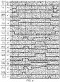
- T0-T7 in FIG. 5 is less than 10 minutes, and T5-T6 is less than 30 seconds.
- T4-T5 represents the initial data interaction, during which exchange of data such as a communication version and the maximum total allowable charging voltage is completed.
- K3 and K4 are required to be opened after the discharging vehicle 200 has transmitted a CSD message and received a BSD message of the battery management system (BMS).
- BMS battery management system
- the bleeder circuit is required to be enabled after the switches K1, K2, K5, and K6 are opened and to exit when the residual voltage is less than 60 V. After a voltage of the CC1 hole changes from 2.1 V to 2.5 V, the bleeder circuit is required to remain cut off.
- a timing diagram and a timing table corresponding to the data in Table 4 and Table 6 are similar to that of the data in Table 1. Only the voltage value of the first detection point a of the discharging vehicle 200 in the timing diagram is required to be modified to a corresponding value, and the voltages of the first detection point a in the T0->T2 row and the T19->T21 row of the timing table are required to be modified to corresponding values.
- the cable assembly in this embodiment of the present disclosure is a movable connection device, which can realize the confirmation of the V2V DC charging connection and the determination of the rated current parameter of the cable, thereby ensuring the safety and the reliability of the V2V DC charging.
- FIG. 6 is a structural block diagram of a vehicle charging system according to an embodiment of the present disclosure.
- the vehicle charging system 1000 includes a discharging vehicle 200, a to-be-charged vehicle 300, and the cable assembly 100 in the above embodiment.
- a discharging outlet 210 is disposed on the discharging vehicle 200
- a charging outlet 310 is disposed on the to-be-charged vehicle 300.
- the discharging outlet 200 charges the to-be-charged vehicle 300
- the discharging outlet 200 is adaptively connected to the power supply plug 110
- the charging outlet 300 is adaptively connected to the charging plug 120.
- the discharging outlet 210 and the charging outlet 310 each include 9 holes: a DC+ hole, a DC- hole, a PE hole, a CANH hole, a CANL hole, an A+ hole, an A-hole, a CC1 hole, and a CC2 hole.
- the power supply plug 110 and the charging plug 120 each include 8 pins
- the DC+ hole, the DC- hole, the PE hole, the CANH hole, the CANL hole, the A+ hole, the A- hole, and the CC1 hole of the discharging outlet 210 are respectively correspondingly connected to the DC+ pin, the DC- plug, the PE pin, the CANH pin, the CANL pin, the A+ pin, the A- pin, and the CC1 pin of the power supply plug 110, and the CC2 hole of the discharging outlet 210 is idle.
- the DC+ hole, the DC- hole, the PE hole, the CANH hole, the CANL hole, the A+ hole, the A- hole, and the CC2 hole of the charging outlet 310 are respectively correspondingly connected to the DC+ pin, the DC- plug, the PE pin, the CANH pin, the CANL pin, the A+ pin, the A- pin, and the CC2 pin of the charging plug 120, and the CC1 hole of the charging outlet 310 is idle.
- the power supply plug 110 and the charging plug 120 each include 9 pins
- the DC+ hole, the DC- hole, the PE hole, the CANH hole, the CANL hole, the A+ hole, the A- hole, the CC1 hole, and the CC2 hole of the discharging outlet 210 are respectively correspondingly connected to the DC+ pin, the DC- pin, the PE pin, the CANH pin, the CANL pin, the A+ pin, the A- pin, the CC1 pin, and the CC2 pin of the power supply plug 110.
- the DC+ hole, the DC- hole, the PE hole, the CANH hole, the CANL hole, the A+ hole, the A- hole, the CC1 hole, and the CC2 hole of the charging outlet 310 are respectively correspondingly connected to the DC+ pin, the DC- pin, the PE pin, the CANH pin, the CANL pin, the A+ pin, the A-pin, the CC1 pin, and the CC2 pin of the charging plug 120.
- the discharging outlet 210 includes a resistor R4.
- One end of the resistor R4 is connected to the PE hole of the discharging outlet 210, and an other end of the resistor R4 is connected to the CC1 hole of the discharging outlet.
- the discharging vehicle 200 includes a power supply device 230, a discharging control device 220, an auxiliary power supply 240, a resistor R1, a resistor R6, a switch K1, a switch K2, a switch K3, a switch K4, and a first body ground GND1.
- a first electrode of the power supply device 230 is connected to the DC+ hole of the discharging outlet 210 by the switch K1.
- a second electrode of the power supply device 230 is connected to the DC- hole of the discharging outlet 210 by the switch K2.
- the first body ground GND1 is connected to the PE hole of the discharging outlet 210.
- the discharging control device 220 is connected to the CANH hole and the CANL hole of the discharging outlet 210 to transmit charging and discharging data.
- a first electrode of the auxiliary power supply 240 is connected to the A+ hole of the discharging outlet 210 by the switch K3.
- a second electrode of the auxiliary power supply 240 is connected to the A- hole of the discharging outlet 210 by the switch K4.
- One end of the resistor R1 is connected to the CC1 hole of the discharging outlet 210 to form a first detection point a.
- An other end of the resistor R1 is connected to a first pull-up voltage U1.
- One end of the resistor R6 is connected to the CC2 hole of the discharging outlet 210 to form a second detection point b.
- An other end of the resistor R6 is connected to a second pull-up voltage U2.
- the charging outlet 310 includes a resistor R4'.
- One end of the resistor R4' is connected to the PE hole of the charging outlet 310, and an other end of the resistor R4' is connected to the CC1 hole of the charging outlet 310.
- the to-be-charged vehicle 300 includes a battery pack 330, a charging control device 320, a resistor R1', a resistor R6', a switch K5, a switch K6, and a second body ground GND2.
- a first electrode of the battery pack 330 is connected to the DC+ hole of the charging outlet 310 by the switch K5.
- a second electrode of the battery pack 330 is connected to the DC- hole of the charging outlet by the switch K6.
- the second body ground GND2 is connected to the PE hole of the charging outlet 310.
- the charging control device 320 is connected to the CANH hole and the CANL hole of the charging outlet 310 to transmit charging and discharging data.
- a positive power supply terminal of the charging control device 320 is connected to the A+ hole of the charging outlet 310.
- a negative power supply terminal of the charging control device 320 is connected to the A- hole of the charging outlet 310.
- One end of the resistor R1' is connected to the CC1 hole of the charging outlet 310 to form a third detection point a'.
- An other end of the resistor R1' is connected to a third pull-up voltage U1'.
- One end of the resistor R6' is connected to the CC2 hole of the charging outlet 310 to form a fourth detection point b'.
- An other end of the resistor R6' is connected to a fourth pull-up voltage U2'.
- the discharging control device 220 is configured to determine that the power supply plug 110 is electrically connected to the discharging outlet 210 when a decrease value of a voltage of the first detection point a is greater than a first preset value.
- the charging control device 320 is configured to determine that the charging plug 120 is electrically connected to the charging outlet 310 when a decrease value of a voltage of the fourth detection point b' is greater than a second preset value.
- the discharging control device 220 is further configured to acquire a rated current of the cable 130 to perform discharging control on the power supply device 230 according to the rated current.
- the vehicle charging system in this embodiment of the present disclosure can realize, by using the movable cable assembly, the confirmation of V2V DC charging connection and the determination of the rated current of the cable, so that the safety and the reliability of the V2V DC charging can be ensured.
- the charging manner is more convenient and can meet the charging requirements of vehicles.
- orientation or position relationships indicated by the terms such as “center”, “longitudinal”, “transverse”, “length”, “width”, “thickness”, “on”, “below”, “front”, “back”, “left”, “right”, “vertical”, “horizontal”, “top”, “bottom”, “inside”, “outside”, “clockwise”, “anticlockwise”, “axial”, “radial”, and “circumferential” are based on orientation or position relationships shown in the accompanying drawings, and are used only for ease and brevity of illustration and description, rather than indicating or implying that the mentioned apparatus or component must have a particular orientation or must be constructed and operated in a particular orientation. Therefore, such terms should not be construed as limiting of the present disclosure.
- first and second are used for descriptive purposes only and are not to be construed as indicating or implying relative importance or implicitly indicating the number of technical features indicated. Therefore, features defining “first” and “second” can explicitly or implicitly include at least one of the features. In the descriptions of the present disclosure, unless explicitly specified, “multiple” means at least two, for example, two or three.
- a connection may be a fixed connection, a detachable connection, or an integral connection; or the connection may be a mechanical connection or an electrical connection; or the connection may be a direct connection, an indirect connection through an intermediary, or internal communication between two elements or mutual action relationship between two elements, unless otherwise specified explicitly.
- a person of ordinary skill in the art can understand specific meanings of the terms in the present disclosure based on specific situations.
- a first feature “on” or “beneath” a second feature may be that the first and second features are in direct contact, or that the first and second features are in indirect contact via an intermediary.
- the first feature “over”, “above” and “up” the second feature may be that the first feature is directly above or obliquely above the second feature, or simply indicates that a horizontal height of the first feature is higher than that of the second feature.
- the first feature “under”, “below” and “down” the second feature may be that the first feature is directly below or obliquely below the second feature, or simply indicates that a horizontal height of the first feature is less than that of the second feature.
Landscapes
- Engineering & Computer Science (AREA)
- Power Engineering (AREA)
- Transportation (AREA)
- Mechanical Engineering (AREA)
- Microelectronics & Electronic Packaging (AREA)
- Electric Propulsion And Braking For Vehicles (AREA)
- Charge And Discharge Circuits For Batteries Or The Like (AREA)
Abstract
Description
- The present disclosure claims priority of
Chinese Patent Application No. 201910703492.3, filled on July 31, 2019 - The present disclosure relates to the technical field of vehicles, and in particular, to a cable assembly and a vehicle charging system.
- With the development of the electric vehicle industry, a fast charging technology has become a key technology for electric vehicles. A dedicated DC charging station (charging cabinet) can achieve quick charging for batteries of the electric vehicles. a connection mode thereof is shown in
FIG. 1 . However, the DC charging stations are generally fixed and immovable and have a limited quantity, and therefore cannot satisfy charging requirements of the electric vehicles. - An objective of the present disclosure is to at least resolve one of the technical problems in the related art to some extent.
- To this end, the present disclosure is intended to provide a cable assembly. The cable assembly can achieve V2V DC charging and has desirable generalization performance.
- The present disclosure is further intended to provide a vehicle charging system.
- In order to achieve the above objectives, an embodiment of a first aspect of the present disclosure provides a cable assembly. The cable assembly includes: a power supply plug, adapted to a discharging outlet of a discharging vehicle; a charging plug, adapted to a charging outlet of a to-be-charged vehicle; and a cable, connected between the power supply plug and the charging plug.
- According to the cable assembly in this embodiment of the present disclosure, the power supply plug and the charging plug are directly connected to the corresponding vehicle outlets and are removable connection devices, can achieve V2V DC charging, and have more desirable generalization performance compared with charging by using a charging cabinet.
- In order to achieve the above objectives, a second aspect of the present disclosure provides a vehicle charging system. The vehicle charging system includes: the cable assembly in the above embodiment; a discharging vehicle, where a discharging outlet is disposed on the discharging vehicle; a to-be-charged vehicle, where a charging outlet is disposed on the to-be-charged vehicle. When the discharging vehicle charges the to-be-charged vehicle, the discharging outlet is adaptively connected to the power supply plug, and the charging outlet is adaptively connected to the charging plug.
- The vehicle charging system in this embodiment of the present disclosure realizes the charging and discharging connection between the discharging vehicle and the to-be-charged vehicle by using cable assembly, can realize V2V DC charging, and has more desirable generalization performance compared with charging connection with a charging cabinet.
- The additional aspects and advantages of the present disclosure will be provided in the following description, some of which will become apparent from the following description or may be learned from practices of the present disclosure.
-
-
FIG. 1 is a schematic structural diagram of a cable assembly in the related art. -
FIG. 2 is a schematic structural diagram of a cable assembly according to an embodiment of the present disclosure. -
FIG. 3 is a circuit diagram of a cable assembly according to an example of the present disclosure. -
FIG. 4 is a circuit diagram of a cable assembly according to another example of the present disclosure. -
FIG. 5 is a timing diagram of charging control according to an example of the present disclosure. -
FIG. 6 is a structural block diagram of a vehicle charging system according to an embodiment of the present disclosure. - The following describes embodiments of the present disclosure in detail. Examples of the embodiments are shown in the accompanying drawings, and same or similar reference numerals in all the accompanying drawings indicate same or similar components or components having same or similar functions. The embodiments described below with reference to the accompanying drawings are exemplary, aiming to explain the present disclosure, but cannot be understood as a limitation on the present disclosure.
- A cable assembly and a vehicle charging system in the embodiments of the present disclosure are described below with reference to the drawings.
-
FIG. 2 is a schematic structural diagram of a cable assembly according to an embodiment of the present disclosure. - As shown in
FIG. 2 , acable assembly 100 includes apower supply plug 110, acharging plug 120, and acable 130. Thepower supply plug 110 is adapted to adischarging outlet 210 of adischarging vehicle 200, and thecharging plug 120 is adapted to acharging outlet 310 of a to-be-charged vehicle 300. Thecable 130 is connected between thepower supply plug 110 and thecharging plug 120. - Therefore, when the to-be-charged
vehicle 300 is required to be charged, only thepower supply plug 110 is required to be adaptively connected to thedischarging outlet 210 of thedischarging vehicle 200 and thecharging plug 120 is required to be adaptively connected to thecharging outlet 310 of the to-be-chargedvehicle 300. In this way, electric energy can be transmitted from thedischarging vehicle 200 to the to-be-chargedvehicle 300 through thecable 130. That is to say, the charging of the to-be-chargedvehicle 300 by thedischarging vehicle 200 is realized. The operation is simple and easy. - In some embodiments of the present disclosure, as shown in
FIG. 3 andFIG. 4 , thecable 130 is composed of a connecting harness. The connecting harness includes a DC+ line, a DC-line, a PE line, a CANH line, a CANL line, an A+ line, and an A- line. - In an example, as shown in
FIG. 3 , thepower supply plug 110 and thecharging plug 120 each include 8 pins. Thepower supply plug 110 includes a DC+ pin, a DC- pin, a PE pin, a CANH pin, a CANL pin, an A+ pin, an A- pin, and a CC1 pin. Thecharging plug 120 includes a DC+ pin, a DC- pin, a PE pin, a CANH pin, a CANL pin, an A+ pin, an A- pin, and a CC2 pin. The DC+ pin, the DC- pin, the PE pin, the CANH pin, the CANL pin, the A+ pin, and the A- pin of each of thepower supply plug 110 and thecharging plug 120 are respectively correspondingly connected to the DC+ line, the DC- line, the PE line, the CANH line, the CANL line, the A+ line, and the A- line. In other words, thepower supply plug 110 and thecharging plug 120 each have 8 pins disposed thereon, and 7 of the pins are the same, and are respectively correspondingly connected to the 7 lines of the connecting harness of thecable 130. The only difference lies in the one different pin. - In this example, as shown in
FIG. 3 , thepower supply plug 110 includes a resistor R2, a resistor R3, and a switch S. One end of the resistor R3 is connected to the PE pin of thepower supply plug 110, an other end of the resistor R3 is connected to one end of the resistor R2, and an other end of the resistor R2 is connected to the CC1 pin of thepower supply plug 110. The switch S is connected in parallel to the resistor R2. Thecharging plug 120 includes a resistor R5'. One end of the resistor R5' is connected to the PE pin of thecharging plug 120, and an other end of the resistor R5' is connected to the CC2 pin of thecharging plug 120. - Therefore, during vehicle charging and discharging, the
power supply plug 110 and thecharging plug 120 cannot be transposed. That is to say, in order to realize the charging of the to-be-chargedvehicle 300 by thedischarging vehicle 200, thepower supply plug 110 is allowed to be connected to only thedischarging outlet 210, and thecharging plug 120 is allowed to be connected to only thecharging outlet 310. In this example, the configurations of the pins of thepower supply plug 110 and thecharging plug 120 are different. In order to further avoid connection errors, a power supply identifier may be disposed on thepower supply plug 110, and/or a charging identifier may be disposed on thecharging plug 120. That is to say, appearances of thepower supply plug 110 and/or thecharging plug 120 are marked differently obviously, for example, by using identifiers of different colors, different texts, or the like. - In another example, as shown in
FIG. 4 , thepower supply plug 110 and thecharging plug 120 have a same structure. Thepower supply plug 110 and thecharging plug 120 each include 9 pins: a DC+ pin, a DC- pin, a PE pin, a CANH pin, a CANL pin, an A+ pin, an A- pin, a CC1 pin, and a CC2 pin. The DC+ pin, the DC- pin, the PE pin, the CANH pin, the CANL pin, the A+ pin, and the A- pin are respectively correspondingly connected to the DC+ line, the DC- line, the PE line, the CANH line, the CANL line, the A+ line and the A- line. In other words, thepower supply plug 110 and thecharging plug 120 each have 9 pins disposed thereon, and the 9 pins are the same. 7 of the pins are respectively correspondingly connected to the 7 lines of the connecting harness of thecable 130. - In this example, referring to
FIG. 4 , thepower supply plug 110 includes a resistor R2, a resistor R3, a switch S, and a resistor R5. One end of the resistor R3 is connected to the PE pin of thepower supply plug 110, an other end of the resistor R3 is connected to one end of the resistor R2, and an other end of the resistor R2 is connected to the CC1 pin of the power supply plug. The switch S is connected in parallel to the resistor R2. One end of the resistor R5 is connected to the PE pin of thepower supply plug 110, and an other end of the resistor R5 is connected to the CC2 pin of thepower supply plug 110. The chargingplug 120 includes a resistor R2', a resistor R3', a switch S', and a resistor R5'. Connection modes thereof are same as the connection modes of the components of thepower supply plug 110. - Thus, during vehicle charging and discharging, the
power supply plug 110 and the chargingplug 120 can be transposed. That is to say, thepower supply plug 110 may be connected to the dischargingoutlet 210 or the chargingoutlet 310. The same is true for the chargingplug 120. In this way, connection errors can be avoided. - In this embodiment of the present disclosure, when the pin of the
power supply plug 110 is inserted into the dischargingoutlet 210 or removed from the dischargingoutlet 210, the switch S may be opened by manual operation. For example, a button may be disposed on thepower supply plug 110. When the button is pressed, the switch S is opened. At this time, the pins of thepower supply plug 110 may be inserted into the dischargingoutlet 210, or the pins of thepower supply plug 110 may be removed from the dischargingoutlet 210. When the pins of thepower supply plug 110 are inserted into the dischargingoutlet 210, the button is released to close the switch S. - In this embodiment of the present disclosure, the discharging
outlet 210 and the chargingoutlet 310 each include a DC+ hole, a DC- hole, a PE hole, a CANH hole, a CANL hole, an A+ hole, an A- hole, a CC1 hole, and a CC2 hole. - In an example, referring to
FIG. 3 , when thepower supply plug 110 and the chargingplug 120 each include 8 pins, the DC+ hole, the DC- hole, the PE hole, the CANH hole, the CANL hole, the A+ hole, the A- hole, and the CC1 hole of the dischargingoutlet 210 are respectively correspondingly connected to the DC+ pin, the DC- plug, the PE pin, the CANH pin, the CANL pin, the A+ pin, the A- pin, and the CC1 pin of thepower supply plug 110, and the CC2 hole of the dischargingoutlet 210 is idle. The DC+ hole, the DC- hole, the PE hole, the CANH hole, the CANL hole, the A+ hole, the A- hole, and the CC2 hole of the chargingoutlet 310 are respectively correspondingly connected to the DC+ pin, the DC- plug, the PE pin, the CANH pin, the CANL pin, the A+ pin, the A- pin, and the CC2 pin of the chargingplug 120, and the CC1 hole of the chargingoutlet 310 is idle. - In another example, referring to
FIG. 4 , when thepower supply plug 110 and the chargingplug 120 each include 9 pins, the DC+ hole, the DC- hole, the PE hole, the CANH hole, the CANL hole, the A+ hole, the A- hole, the CC1 hole, and the CC2 hole of the dischargingoutlet 210 are respectively correspondingly connected to the DC+ pin, the DC- pin, the PE pin, the CANH pin, the CANL pin, the A+ pin, the A- pin, the CC1 pin, and the CC2 pin of thepower supply plug 110. The DC+ hole, the DC- hole, the PE hole, the CANH hole, the CANL hole, the A+ hole, the A- hole, the CC1 hole, and the CC2 hole of the chargingoutlet 310 are respectively correspondingly connected to the DC+ pin, the DC- pin, the PE pin, the CANH pin, the CANL pin, the A+ pin, the A- pin, the CC1 pin, and the CC2 pin of the chargingplug 120. - Referring to
FIG. 3 andFIG. 4 , the dischargingoutlet 210 includes a resistor R4. One end of the resistor R4 is connected to the PE hole of the dischargingoutlet 210, and an other end of the resistor R4 is connected to the CC1 hole of the discharging outlet. The dischargingvehicle 200 includes apower supply device 230, a dischargingcontrol device 220, a resistor R1, a resistor R6, a switch K1, a switch K2, a switch K3, a switch K4, and a first body ground GND1. A first electrode of thepower supply device 230 is connected to the DC+ hole of the dischargingoutlet 210 by the switch K1. A second electrode of thepower supply device 230 is connected to the DC- hole of the dischargingoutlet 210 by the switch K2. The first body ground GND1 is connected to the PE hole of the dischargingoutlet 210. The dischargingcontrol device 220 is connected to the CANH hole and the CANL hole of the dischargingoutlet 210 to transmit charging and discharging data. A first electrode of an auxiliary power supply in the dischargingcontrol device 220 is connected to the A+ hole of the dischargingoutlet 210 by the switch K3. A second electrode of the auxiliary power supply is connected to the A- hole of the dischargingoutlet 210 by the switch K4. One end of the resistor R1 is connected to the CC1 hole of the dischargingoutlet 210 to form a first detection point a. An other end of the resistor R1 is connected to a first pull-up voltage U1. One end of the resistor R6 is connected to the CC2 hole of the dischargingoutlet 210 to form a second detection point b. An other end of the resistor R6 is connected to a second pull-up voltage U2. - Referring to
FIG. 3 andFIG. 4 , the chargingoutlet 310 includes a resistor R4'. One end of the resistor R4' is connected to the PE hole of the chargingoutlet 310, and an other end of the resistor R4' is connected to the CC1 hole of the chargingoutlet 310. The to-be-charged vehicle 300 includes abattery pack 330, a chargingcontrol device 320, a resistor R1', a resistor R6', a switch K5, a switch K6, and a second body ground GND2. A first electrode of thebattery pack 330 is connected to the DC+ hole of the chargingoutlet 310 by the switch K5. A second electrode of thebattery pack 330 is connected to the DC- hole of the charging outlet by the switch K6. The second body ground GND2 is connected to the PE hole of the chargingoutlet 310. The chargingcontrol device 320 is connected to the CANH hole and the CANL hole of the chargingoutlet 310 to transmit charging and discharging data. A positive power supply terminal of the chargingcontrol device 320 is connected to the A+ hole of the chargingoutlet 310. A negative power supply terminal of the chargingcontrol device 320 is connected to the A- hole of the chargingoutlet 310. One end of the resistor R1' is connected to the CC1 hole of the chargingoutlet 310 to form a third detection point a'. An other end of the resistor R1' is connected to a third pull-up voltage U1'. One end of the resistor R6' is connected to the CC2 hole of the chargingoutlet 310 to form a fourth detection point b'. An other end of the resistor R6' is connected to a fourth pull-up voltage U2'. - It should be noted that, in the example shown in
FIG. 3 , the CC2 hole of the dischargingoutlet 210 and the CC1 hole of the chargingoutlet 310 are idle. Therefore, the resistor R6 of the dischargingvehicle 200 and the resistors R4' and R1' of the to-be-charged vehicle 300 are not shown inFIG. 3 . - In an embodiment of the present disclosure, the four pull-up voltages U1, U2, U1', and U2' are equal, for example, are all U.
- The discharging
control device 220 is configured to determine that thepower supply plug 110 is electrically connected to the dischargingoutlet 210 when a decrease value of a voltage of the first detection point a is greater than a first preset value. The chargingcontrol device 320 is configured to determine that the chargingplug 120 is electrically connected to the chargingoutlet 310 when a decrease value of a voltage of the fourth detection point b' is greater than a second preset value. - Specifically, referring to
FIG. 3 andFIG. 4 , when the switch S is opened and the pins of thepower supply plug 110 are not inserted into the dischargingoutlet 210, the pull-up voltage U1 supplies power to only the resistors R1 and R4 connected in series, and the voltage of the first detection point a is relatively large. When the switch S is opened and the pins of thepower supply plug 110 are inserted into the dischargingoutlet 210, the pull-up voltage U1 supplies power to the resistors R1, R4, R2, and R3. R2 and R3 connected in series are connected in parallel to R4 and then connected in series to R1. The voltage of the first detection point a is reduced. When the switch S is closed and the pins of thepower supply plug 110 are inserted into the dischargingoutlet 210, the pull-up voltage U1 supplies power to the resistors R1, R4, and R3. R3 is connected in parallel to R4 and then connected in series to R1. The voltage of the first detection point a is further reduced. Therefore, based on the settings of the resistors R2 and R3 and the switch S, the status of the connection between thepower supply plug 110 and the dischargingoutlet 210 may be accurately determined by using the voltage value of the first detection point a. - It should be understood that the
power supply device 230 corresponds to thebattery pack 330, the switches K1 and K2 correspond to the switches K5 and K6, the resistors R1 and R6 correspond to the resistors R1' and R6', and the dischargingcontrol device 220 corresponds to the chargingcontrol device 320. It should be noted that two switches corresponding to the switches K3 and K4 are further required to be disposed in the to-be-charged vehicle 300. When the dischargingcontrol device 220 determines that thepower supply plug 110 is completely inserted into the dischargingoutlet 210, that is, thepower supply plug 110 is completely connected to the dischargingoutlet 210, the control switches K3 and K4 are closed. - In this embodiment of the present disclosure, during charging of the to-
be-charged vehicle 300, if the chargingcontrol device 320 of the to-be-charged vehicle 300 does not require power supply from an auxiliary power supply, the switches K3 and K4 may not be disposed in the dischargingvehicle 200. - In an embodiment of the present disclosure, a bleeder circuit and an insulation detection circuit are further disposed on each of the discharging
vehicle 200 and the to-be-charged vehicle 300. For example, in the dischargingvehicle 200, one end of the bleeder circuit is connected to a line connecting the switch K1 to thepower supply device 230, and an other end of the bleeder circuit is connected to a line connecting the switch K2 to thepower supply device 230. A first end of the insulation detection circuit is connected to the line connecting the switch K1 to thepower supply device 230, a second end of the insulation detection circuit is connected to the line connecting the switch K2 to thepower supply device 230, and a third end of the insulation detection circuit is connected to the first body ground GND1. In addition, the bleeder circuit and the insulation detection circuit each have a switching function. - The charging of the to-
be-charged vehicle 300 by the dischargingvehicle 200 in the example shown inFIG. 4 is described below with reference to Table 1, Table 2, Table 3, andFIG. 5 . Table 1 shows parameters such as resistances and voltages inFIG. 4 .Table 1 Object Parameter Symbol Unit Nominal value Discharging vehicle 200 Equivalent resistance of R1 R1 Ω 1000 Equivalent resistance of R6 R6 Ω 1000 Pull-up voltage U V 5 Voltage of first detection point a U1a V 2.5 U1b V 2.1 U1c V 1.7/1.3/0.9/0.5 V Discharging outlet Equivalent resistance of R4 R4 Ω 1000 Power supply plug Equivalent resistance of R5 R5 Ω 1000 Charging plug Equivalent resistance of R5' R5' Ω 1000 Charging outlet Equivalent resistance of R4' R4' Ω 1000 To- be-charged vehicle 300Equivalent resistance of R1' R1' Ω 1000 Equivalent resistance of R6' R6' Ω 1000 Pull-up voltage U V 5 Voltage of fourth detection point b' U2a V 5 U2b V 2.5 - As shown in
FIG. 4 , the switch S of thepower supply plug 110 is pressed to open the switch S, and thepower supply plug 110 is inserted into the dischargingoutlet 210 of the dischargingvehicle 200. After the insertion is completed, the switch S of thepower supply plug 110 is released to restore the switch S to a normal close state, so that thepower supply plug 110 is completely connected to the dischargingoutlet 210. The chargingplug 120 is inserted into the chargingoutlet 310 of the to-be-charged vehicle 300 in the same way according to the above operations. - During the insertion of the
power supply plug 110 into the dischargingoutlet 210, a change in the voltage of the first detection point a of the dischargingvehicle 200 is as follows: 2.5 V->2.1 V->1.7 V/1.3 V/0.9 V/0.5 V. 2.5 V represents that thepower supply plug 110 is not connected to the dischargingoutlet 210. 2.1 V represents that thepower supply plug 110 is half connected to the dischargingoutlet 210. 1.7 V/1.3 V/0.9 V/0.5 V represents that thepower supply plug 110 is completely connected to the dischargingoutlet 210. During the insertion of the chargingplug 120 into the chargingoutlet 310, a change in the voltage of the fourth detection point b' of the to-be-charged vehicle 300 is as follows: 5 V->2.5 V. - It should be noted that, during the insertion of the connecting component into the outlet, turn-on of the switch S may be used as a trigger condition. Therefore, when the switch S is turned on, the vehicle is caused to enter a travel-forbidden state through interlocking or other control measures. Optionally, the trigger condition may be opening a charging and discharging outlet cover, connecting an adapter component to the vehicle outlet, and operating a charging and discharge button/switch of the vehicle.
- After an operator sets charging of the discharging
vehicle 200, the dischargingcontrol device 220 of the dischargingvehicle 200 determines whether thepower supply plug 110 is completely connected to the dischargingoutlet 210 by measuring the voltage value of the first detection point a. If the voltage value of the first detection point a is one of 1.7 V/1.3 V/0.9 V/0.5 V, it is determined that thepower supply plug 110 is completely connected to the dischargingoutlet 210. - After the
power supply plug 110 is completely connected to the dischargingoutlet 210, the switches K3 and K4 are closed so that a low-voltage auxiliary power supply loop is connected. The switches K1 and K2 are closed to perform insulation detection. An output voltage during the insulation detection is a smaller value of an insulation voltage in a vehicle communication handshake message and a rated voltage of thepower supply device 230. After the insulation detection is completed, the insulation detection circuit is physically separated from the power supply loop, and the bleeder circuit is enabled to discharge a charging output voltage. After the dischargingvehicle 200 completes the self-check, K1 and K2 are opened, and the communication handshake message is periodically transmitted. If the to-be-charged vehicle 300 requires the dischargingvehicle 200 to provide an auxiliary power supply 240, after the auxiliary power supply 240 provided by the dischargingvehicle 200 is obtained, the chargingcontrol device 320 of the to-be-charged vehicle 300 determines whether the chargingplug 120 is completely connected to the chargingoutlet 310 by measuring the voltage value of the fourth detection point b'. If the to-be-charged vehicle 300 does not require the dischargingvehicle 200 to provide an auxiliary voltage, the chargingcontrol device 320 directly measures the voltage value of the fourth detection point b' to determine whether the chargingplug 120 is connected to the chargingoutlet 310. If the voltage value of the fourth detection point b' is 2.5 V, the chargingcontrol device 320 of the to-be-charged vehicle 300 starts to periodically transmit the communication handshake message. - In a configuration phase of the charging
control device 320 and the dischargingcontrol device 220, the chargingcontrol device 320 controls the switches K5 and K6 to be closed, so that the charging loop is connected. After the dischargingcontrol device 220 detects that a voltage of thebattery pack 330 of the to-be-charged vehicle 300 is normal (that is, determines that the voltage of the battery pack is greater than a minimum output voltage of thepower supply device 230 and less than a maximum output voltage of the power supply device 230), the discharging control device controls the switches K1 and K2 to be closed, so that the DC power supply loop is connected. - In the charging phase, the charging
control device 320 transmits a battery charging requirement parameter to the dischargingcontrol device 220 in real time. When a charging current decreases such that ΔI ≤ 20 A, the charging control adjusts the charging current to be same as a command value within a longest time of Is. When a charging current decreases such that ΔI > 20 A, the charging control adjusts the charging current to be same as the command value within AI/dlmin s (dlmin is a minimum charging rate, which is 20 A/s). The dischargingcontrol device 220 adjusts the charging voltage and the charging current in real time according to the battery charging demand parameter. In addition, the chargingcontrol device 320 and the dischargingcontrol device 220 further transmit respective status information to each other. During the charging, the chargingcontrol device 320 is required to be able to detect disconnection of the PE pin. - The charging
control device 320 determines whether to end the charging according to whether a battery system reaches a fully charged state or whether a message instructing to end charging by the discharging vehicle. When any of the above charging ending conditions is met, the chargingcontrol device 320 starts to periodically transmit a message instructing to end charging by the charging control device (or a battery management system), and opens the switches K5 and K6 after it is determined that the charging current is less than 5 A. When the charging ending condition set by the operator is met or the message instructing to end charging by the charging control device (or the battery management system) is received, the dischargingcontrol device 220 periodically transmits the message instructing to end charging by the discharging vehicle and controls the dischargingvehicle 200 to stop charging and reduce the charging current at a rate not less than 100 A/s. When the charging current is less than or equal to 5 A, the switches K1 and K2 are opened. When the operator implements the charging ending instruction, the dischargingcontrol device 220 starts to periodically transmit the message instructing to end charging by the discharging vehicle, and controls the dischargingvehicle 200 to stop charging. When it is determined that the charging current is less than 5 A, the switches K1 and K2 are opened, the bleeder circuit is enabled again, and then the switches K3 and K4 are opened. - During the charging, if the discharging
vehicle 200 fails to continue to perform charging, the message instructing to end charging by the discharging vehicle is periodically transmitted to the to-be-charged vehicle 300, and the discharging vehicle is controlled to stop charging. The current value is required to be reduced to 5 A within 50 ms or the switches K1, K2, K3 and K4 are required to be opened within 100 ms. - During the charging, if the to-
be-charged vehicle 300 fails to continue to be charged, a message instructing to end charging to the to-be-charged vehicle is transmitted to the dischargingvehicle 200, and the switches K5 and K6 are opened within 300 ms. - During the charging, if the discharging
control device 220 determines that the communication is interrupted, the dischargingvehicle 200 stops charging and opens the switches K1, K2, K3, and K4. - During the charging, the discharging
control device 220 detects the voltage of the first detection point a. If it is determined that the switch S of thepower supply plug 110 is changed from close to open, the output current is required to be reduced to 5 A or less within 50 ms. - During the charging, the discharging
control device 220 detects the voltage of the first detection point a. If it is determined that thepower supply plug 110 and the dischargingoutlet 210 are changed from being completely connected to being disconnected, the dischargingvehicle 200 is controlled to stop charging, and the switches K1, K2, K3, and K4 are opened. - During the charging, if the output voltage of the
power supply device 230 is greater than a maximum total allowable charging voltage of the to-be-charged vehicle 300, the dischargingvehicle 200 is controlled to stop charging. - Certainly, if the discharging
vehicle 200 ends charging due to a serious fault, the charging is restarted, which requires the operator to perform a complete setting to restart the charging. -
- 1) An insulation detection circuit is disposed in each of the discharging
vehicle 200 and the to-be-charged vehicle 300. After thepower supply plug 110 is inserted into the dischargingoutlet 210 and the chargingplug 120 is inserted into the chargingoutlet 310 and before the switches K5 and K6 are closed for charging, the dischargingvehicle 200 is responsible for insulation inspection of an interior of the discharging vehicle 200 (including insulation inspection of the charging cable). The insulation detection circuit of the dischargingvehicle 200 is disconnected from the charging DC loop by using the switch. During the charging after the switches K5 and K6 are closed, the to-be-charged vehicle 300 is responsible for insulation inspection of the entire system. For insulation resistances between DC+ and PE and between DC- and PE of the charging DC circuit (a small value R of the two is used), when R > 500 Ω/V, safety is determined. When 100 Ω/V < R < 500 Ω/V, insulation abnormality alarming may be performed, but the charging can normally proceed. When R < 100 Ω/V, an insulation failure is determined, and the charging is required to be stopped. - 2) After the insulation detection of the discharging
vehicle 200, the charging output voltage is required to be discharged in time to avoid voltage impact on a battery load in the charging phase. After the charging ends, the dischargingvehicle 200 is required to discharge the charging output voltage in time to avoid electric damage to the operator. Parameters of the bleeder circuit are required to be selected in such a way that a voltage of a power supply interface decreases to be less than 60 VDC within 1 second after a charging connector is disconnected. - 3) When the charging loop or the control loop loses power due to a power failure, the discharging
vehicle 200 is required to open the switches K1 and K2 within 1 second or reduce the voltage of the charging interface to be less than 60 VDC within 1 second by using the bleeder circuit. - As described above, the discharging
vehicle 200 may determine whether thepower supply plug 110 is completely connected to the dischargingoutlet 210 by using a resistance value between the first detection point a and PE (the voltage value of the first detection point a) and the rated current parameter of thecable 130. For specific determination the connection status and the rated current parameter, refer to Table 2.Table 2 Status R3 R2 s U1 Interface connection status and rated current State A - - 2.5 V The vehicle interface is not completely connected State B - Open 2.5 V The mechanical locking device is unlocked State C 1.1 KΩ/0.5Wa - Close 1.7 V The vehicle interface is completely connected, and the capacity of the charging cable is 80 A State C' 1.1 KΩ/0.5Wa 1.5 KΩ/0.5Wb Open 2.1 V The vehicle interface is in a half-connected state State D 560 Ω/0.5Wa - Close 1.3 V The vehicle interface is completely connected, and the capacity of the charging cable is 125 A. State D' 560 Ω/0.5Wa 2 KΩ/0.5Wb Open 2.1 V The vehicle interface is in a half-connected state State E 270 Ω/0.5Wa - Close 0.9 V The vehicle interface is completely connected, and the capacity of the charging cable is 200 A State E' 270 Ω/0.5Wa 2.4 KΩ/0.5Wb Open 2.1 V The vehicle interface is in a half-connected state State F 125 Ω/0.5Wa - Close 0.5 V The vehicle interface is completely connected, and the capacity of the charging cable is 250 A State F' 125 Ω/0.5Wa 2.4 KΩ/0.5Wb Open 2.1 V The vehicle interface is in a half-connected state - In the half-connected state, the equivalent resistance is a resistance obtained after R2 and R3 are connected in series and then connected in parallel to R4 and then connected in series to R1. All detected voltages U1 are 2.1 V. In the complete connected state, the equivalent resistance is a resistance obtained after R3 and R4 are connected in parallel and then connected in series to R1. When the resistance values of the resistors R3 and R2 configured in the
cable assembly 100 are different, the detected voltages U1 are different afterdifferent cable assemblies 100 are completely connected. The capacity of the charging cable is 80 A when U1 is 1.7 V, the capacity of the charging cable is 125 A when U1 is 1.3 V, the capacity of the charging cable is 200 A when U1 is 0.9 V, and the capacity of the charging cable is 250 A when U1 is 0.5 V. - The above DC charging connection process and control timing are shown in
FIG. 5 , and description of the control timing is shown in Table 3:Table 3 T0 When the vehicle interface is not connected, the protective switch S of the connecting component is pressed to open the switch S. T1 When the vehicle interface is not completely connected, the switch S is maintained in the open state, and the connecting component is inserted into the vehicle outlet. T2 After the connecting component is inserted into the vehicle outlet, the switch S is released so that the switch S normally closed. In this case, the vehicle interface is completely connected. T2' An electronic locker feeds back a reliable locking signal T0->T2 During the insertion of the connecting component into the vehicle outlet, the voltage of the first detection point a of the discharging vehicle changes as follows: 2.5 V->2.1 V->1.7 V/1.3 V/0.9 V/0.5 V, and the voltage of the fourth detection point b' of the to-be-charged vehicle changes as follows: 5 V->2.5 V. T3 The discharging vehicle closes the switches K3 and K4 so that the low-voltage auxiliary power supply loop is connected. T4 The discharging vehicle enables the handshake message. T4->T5 Initial data exchange is performed. The discharging vehicle acquires the maximum total allowable charging voltage and the rated current of the charging cable. After obtaining the low-voltage auxiliary power supply provided by the discharging vehicle, the charging control device determines whether the vehicle interface is fully connected by measuring the voltage value of the fourth detection point b'. If the voltage value of the fourth detection point b' is 2.5 V, the charging control device waits for the handshake message transmitted by the discharging vehicle, and periodically transmits a handshake message after receiving the handshake message transmitted by the discharging vehicle. T6 The discharging vehicle closes an insulation detection circuit switch and enables insulation monitoring. T7 The discharging vehicle closes the switches K1 and K2, and the output voltage is an insulation monitoring voltage. The insulation monitoring voltage is a smaller one of the maximum total allowable charging voltage and the rated voltage of the discharging vehicle. T8 The insulation detection ends, and the insulation detection circuit switch is opened. T9 A bleeder circuit switch is closed, and discharging is enabled. T10 After a residual voltage is discharged, the bleeder circuit is cut off, and a DC output contactor is cut off. T6-T10 After the discharging vehicle receives the maximum total allowable voltage of the to-be-charged vehicle, the discharging vehicle is responsible for the insulation inspection of the interior of the discharging vehicle (including the insulation inspection of the charging cable). For insulation resistances between DC+ and PE and between DC- and PE of the charging DC circuit (a small value R of the two is used), when R > 500 Ω/V, safety is determined. When 100 Ω/V < R < 500 Ω/V, insulation abnormality alarming may be performed, but the charging can normally proceed. When R < 100 Ω/V, an insulation failure is determined, and the charging is required to be stopped. T11 The discharging vehicle starts to periodically transmit a communication identification message. The charging control device waits for the communication identification message transmitted by the discharging vehicle, and periodically transmits the identification message after receiving the identification message transmitted bv the discharging vehicle. T12 The to-be-charged vehicle is ready for charging, and the charging control device closes the switches K5 and K6 so that the charging loop is connected. The to-be-charged vehicle is responsible for insulation inspection of the entire system. T13 The discharging control device detects that the battery voltage of the to-be-charged vehicle is normal (determines that the battery voltage is greater than the minimum output voltage of the discharging vehicle and less than the maximum output voltage of the discharging vehicle), and the discharging vehicle outputs a pre-charging voltage and then closes the switches K1 and K2 so that the DC power supply loop is connected. In the charging phase, after the output voltage of the discharging vehicle reaches the battery voltage of the to-be-charged vehicle, the charging voltage and the charging current are adjusted according to the battery charging requirement transmitted by the to-be-charged vehicle in real time, and the charging status is exchanged with each other. T12-T13 The output voltage of the discharging vehicle is the pre-charging voltage, which is a current battery voltage minus 10 V. T14 When the charging ending condition is met, the charging control device starts to periodically transmit a message instructing to end charging by a battery management system, and the discharging vehicle periodically transmits a message instructing to end charging by the discharging vehicle, and controls the discharging vehicle to stop charging. The discharging vehicle stops outputting, and the output current is 5 A or less. T15 The charging control device opens the switches K5 and K6. The discharging vehicle opens the switches K1 and K2. The to-be-charged vehicle stops the insulation monitoring. T16 The discharging vehicle closes the circuit switch to discharge the output voltage, so as to avoid electric damage to the operator. T17 When the output voltage of the discharging vehicle decreases to be less than 60 V, the bleeder circuit switch is opened. The discharging vehicle opens the switches K3 and K4. The two parties stop communication and interaction. T18 The electronic locker feeds back an unlocking signal. T19 The switch S of the connecting component is pressed to open the switch S. T20 The switch S is maintained in the open state, and the connecting component is removed from the vehicle outlet. T21 When the connecting component is completely separated from the vehicle outlet, the switch S is released. T19->T21 During disconnection of the connecting component from the vehicle outlet, the voltage of the first detection point a of the discharging vehicle changes as follows: 0.4 V/0.9 V/1.3 V/1.7 V->2.1 V->2.5 V, and the voltage of the fourth detection point b' of the to-be-charged vehicle changes as follows: 2.5 V->5 V. - It should be noted that when there is no charging appointment, T0-T7 in
FIG. 5 is less than 10 minutes, and T5-T6 is less than 30 seconds. When there is a charging appointment, there is no time limit for T0-T7 and T5-T6. T4-T5 represents the initial data interaction, during which exchange of data such as a communication version and the maximum total allowable charging voltage is completed. K3 and K4 are required to be opened after the dischargingvehicle 200 has transmitted a CSD message and received a BSD message of the battery management system (BMS). After the charging is completed, the bleeder circuit is required to be enabled after the switches K1, K2, K5, and K6 are opened and to exit when the residual voltage is less than 60 V. After a voltage of the CC1 hole changes from 2.1 V to 2.5 V, the bleeder circuit is required to remain cut off. - In addition, in this embodiment of the present disclosure, other two sets of data are available for the setting parameters of the
cable assembly 100, as shown in Table 4 and Table 6. Determination of an interface connection status and a rated current parameter corresponding to Table 4 is shown in Table 5, and determination of an interface connection status and a rated current parameter corresponding to Table 6 is shown in Table 7.Table 4 Object Parameter Symbol Unit Nominal value Discharging vehicle 200 Equivalent resistance of R1 R1 Ω 110 Equivalent resistance of R6 equivalent R6 Ω 1000 First pull-up voltage U1 V 5 Voltage of first detection point a U1a V 4.5 U1b V 4 U1c V 3/2/1/0.5 Discharging outlet Equivalent resistance of R4 R4 Ω 1000 Power supply plug Equivalent resistance of R5 R5 Ω 1000 Charging plug Equivalent resistance of R5' R5' Ω 1000 Charging outlet Equivalent resistance of R4' R4' Ω 1000 To-be-charged vehicle 300 Equivalent resistance of R1' R1' Ω 110 Equivalent resistance of R6' R6' Ω 1000 Fourth pull-up voltage U2' V 5 Voltage of fourth detection point b' U2a V 5 U2b V 2.5 Table 5 Status R3 R2 s U1 Interface connection status and rated current State A - - 4.5 V The vehicle interface is not completelv connected State B - Open 4.5 V The mechanical locking device is unlocked State C 200 Ω/0.5Wa - Close 3 V The vehicle interface is completely connected, and the capacity of the charging cable is 80 A State C' 200 Ω/0.5Wa 620 Ω/0.5Wb Open 4 V The vehicle interface is in a half-connected state State D 82 Ω/0.5Wa - Close 2 V The vehicle interface is completely connected, and the capacity of the charging cable is 125 A State D' 82 Ω/0.5Wa 750 Ω/0.5Wb Open 4 V The vehicle interface is in a half-connected state State E 27 Ω/0.5Wa - Close 1 V The vehicle interface is completely connected, and the capacity of the charging cable is 200 A State E' 27 Ω/0.5Wa 750 Ω/0.5Wb Open 4 V The vehicle interface is in a half-connected state State F 12 Ω/0.5Wa - Close 0.5 V The vehicle interface is completely connected, and the capacity of the charging cable is 250 A State F' 12 Ω/0.5Wa 750 Ω/0.5Wb Open 4 V The vehicle interface is in a half-connected state Table 6 Object Parameter Symbol Unit Nominal value Discharging vehicle 200 Equivalent resistance of R1 R1 Ω 1000 Equivalent resistance of R6 R6 Ω 1000 First pull-up voltage U V 5 Voltage of first detection point a U1a V 2.5 U1b V 2 U1c V 1.5/1.0/0.5 V Discharging outlet Equivalent resistance of R4 R4 Ω 1000 Power supply plug Equivalent resistance of R5 R5 Ω 1000 Charging plug Equivalent resistance of R5' R5' Ω 1000 Charging outlet Equivalent resistance of R4' R4' Ω 1000 To-be-charged vehicle 300 Equivalent resistance of R1' R1' Ω 1000 Equivalent resistance of R6' R6' Ω 1000 Fourth pull-up voltage U V 5 Voltage of fourth detection point b' U2a V 5 U2b V 2.5 Table 7 Status R3 R2 s U1 Interface connection status and rated current State A - - 2.5 V The vehicle interface is not completely connected State B - Open 2.5 V The mechanical locking device is unlocked State C 750 Ω/0.5Wa - Close 1.5 V The vehicle interface is completely connected, and the capacity of the charging cable is 80 A State C' 750 Ω/0.5Wa 1.2 KΩ/0.5Wb Open 2 V The vehicle interface is in a half-connected state State D 330 Ω/0.5Wa - Close 1.0 V The vehicle interface is completely connected, and the capacity of the charging cable is 125 A State D' 330 Ω/0.5Wa 1.6 KΩ/0.5Wb Open 2 V The vehicle interface is in a half-connected state State E 120 Ω/0.5Wa - Close 0.5 V The vehicle interface is completely connected, and the capacity of the charging cable is 200 A State E' 120 Ω/0.5Wa 1.8 KΩ/0.5Wb Open 2 V The vehicle interface is in a half-connected state - A timing diagram and a timing table corresponding to the data in Table 4 and Table 6 are similar to that of the data in Table 1. Only the voltage value of the first detection point a of the discharging
vehicle 200 in the timing diagram is required to be modified to a corresponding value, and the voltages of the first detection point a in the T0->T2 row and the T19->T21 row of the timing table are required to be modified to corresponding values. - Advantages and disadvantages of the three sets of data are as follows: In Table 4, the requirements on a precision of a device required for detecting the voltage of the first detection point a are the lowest, but power consumption of the resistor R1 is high. Power consumption of the resistors in Table 1 and Table 6 is very small, but a rated current of a connecting device corresponding to Table 6 has only three gears. Comprehensively, the data in Table 1 is the optimal.
- In conclusion, the cable assembly in this embodiment of the present disclosure is a movable connection device, which can realize the confirmation of the V2V DC charging connection and the determination of the rated current parameter of the cable, thereby ensuring the safety and the reliability of the V2V DC charging.
-
FIG. 6 is a structural block diagram of a vehicle charging system according to an embodiment of the present disclosure. - As shown in
FIG. 6 , thevehicle charging system 1000 includes a dischargingvehicle 200, a to-be-charged vehicle 300, and thecable assembly 100 in the above embodiment. - Specifically, a discharging
outlet 210 is disposed on the dischargingvehicle 200, and a chargingoutlet 310 is disposed on the to-be-charged vehicle 300. When the dischargingvehicle 200 charges the to-be-charged vehicle 300, the dischargingoutlet 200 is adaptively connected to thepower supply plug 110, and the chargingoutlet 300 is adaptively connected to the chargingplug 120. - In this embodiment, the discharging
outlet 210 and the chargingoutlet 310 each include 9 holes: a DC+ hole, a DC- hole, a PE hole, a CANH hole, a CANL hole, an A+ hole, an A-hole, a CC1 hole, and a CC2 hole. - In an example, as shown in
FIG. 3 , when thepower supply plug 110 and the chargingplug 120 each include 8 pins, the DC+ hole, the DC- hole, the PE hole, the CANH hole, the CANL hole, the A+ hole, the A- hole, and the CC1 hole of the dischargingoutlet 210 are respectively correspondingly connected to the DC+ pin, the DC- plug, the PE pin, the CANH pin, the CANL pin, the A+ pin, the A- pin, and the CC1 pin of thepower supply plug 110, and the CC2 hole of the dischargingoutlet 210 is idle. The DC+ hole, the DC- hole, the PE hole, the CANH hole, the CANL hole, the A+ hole, the A- hole, and the CC2 hole of the chargingoutlet 310 are respectively correspondingly connected to the DC+ pin, the DC- plug, the PE pin, the CANH pin, the CANL pin, the A+ pin, the A- pin, and the CC2 pin of the chargingplug 120, and the CC1 hole of the chargingoutlet 310 is idle. - In another example, as shown in
FIG. 4 , when thepower supply plug 110 and the chargingplug 120 each include 9 pins, the DC+ hole, the DC- hole, the PE hole, the CANH hole, the CANL hole, the A+ hole, the A- hole, the CC1 hole, and the CC2 hole of the dischargingoutlet 210 are respectively correspondingly connected to the DC+ pin, the DC- pin, the PE pin, the CANH pin, the CANL pin, the A+ pin, the A- pin, the CC1 pin, and the CC2 pin of thepower supply plug 110. The DC+ hole, the DC- hole, the PE hole, the CANH hole, the CANL hole, the A+ hole, the A- hole, the CC1 hole, and the CC2 hole of the chargingoutlet 310 are respectively correspondingly connected to the DC+ pin, the DC- pin, the PE pin, the CANH pin, the CANL pin, the A+ pin, the A-pin, the CC1 pin, and the CC2 pin of the chargingplug 120. - In this embodiment of the present disclosure, as shown in
FIG. 3 andFIG. 4 , the dischargingoutlet 210 includes a resistor R4. One end of the resistor R4 is connected to the PE hole of the dischargingoutlet 210, and an other end of the resistor R4 is connected to the CC1 hole of the discharging outlet. The dischargingvehicle 200 includes apower supply device 230, a dischargingcontrol device 220, an auxiliary power supply 240, a resistor R1, a resistor R6, a switch K1, a switch K2, a switch K3, a switch K4, and a first body ground GND1. A first electrode of thepower supply device 230 is connected to the DC+ hole of the dischargingoutlet 210 by the switch K1. A second electrode of thepower supply device 230 is connected to the DC- hole of the dischargingoutlet 210 by the switch K2. The first body ground GND1 is connected to the PE hole of the dischargingoutlet 210. The dischargingcontrol device 220 is connected to the CANH hole and the CANL hole of the dischargingoutlet 210 to transmit charging and discharging data. A first electrode of the auxiliary power supply 240 is connected to the A+ hole of the dischargingoutlet 210 by the switch K3. A second electrode of the auxiliary power supply 240 is connected to the A- hole of the dischargingoutlet 210 by the switch K4. One end of the resistor R1 is connected to the CC1 hole of the dischargingoutlet 210 to form a first detection point a. An other end of the resistor R1 is connected to a first pull-up voltage U1. One end of the resistor R6 is connected to the CC2 hole of the dischargingoutlet 210 to form a second detection point b. An other end of the resistor R6 is connected to a second pull-up voltage U2. - As shown in
FIG. 3 andFIG. 4 , the chargingoutlet 310 includes a resistor R4'. One end of the resistor R4' is connected to the PE hole of the chargingoutlet 310, and an other end of the resistor R4' is connected to the CC1 hole of the chargingoutlet 310. The to-be-charged vehicle 300 includes abattery pack 330, a chargingcontrol device 320, a resistor R1', a resistor R6', a switch K5, a switch K6, and a second body ground GND2. A first electrode of thebattery pack 330 is connected to the DC+ hole of the chargingoutlet 310 by the switch K5. A second electrode of thebattery pack 330 is connected to the DC- hole of the charging outlet by the switch K6. The second body ground GND2 is connected to the PE hole of the chargingoutlet 310. The chargingcontrol device 320 is connected to the CANH hole and the CANL hole of the chargingoutlet 310 to transmit charging and discharging data. A positive power supply terminal of the chargingcontrol device 320 is connected to the A+ hole of the chargingoutlet 310. A negative power supply terminal of the chargingcontrol device 320 is connected to the A- hole of the chargingoutlet 310. One end of the resistor R1' is connected to the CC1 hole of the chargingoutlet 310 to form a third detection point a'. An other end of the resistor R1' is connected to a third pull-up voltage U1'. One end of the resistor R6' is connected to the CC2 hole of the chargingoutlet 310 to form a fourth detection point b'. An other end of the resistor R6' is connected to a fourth pull-up voltage U2'. - The discharging
control device 220 is configured to determine that thepower supply plug 110 is electrically connected to the dischargingoutlet 210 when a decrease value of a voltage of the first detection point a is greater than a first preset value. The chargingcontrol device 320 is configured to determine that the chargingplug 120 is electrically connected to the chargingoutlet 310 when a decrease value of a voltage of the fourth detection point b' is greater than a second preset value. - In this embodiment of the present disclosure, the discharging
control device 220 is further configured to acquire a rated current of thecable 130 to perform discharging control on thepower supply device 230 according to the rated current. - It should be noted that, for other specific implementations of the vehicle charging system in this embodiment of the present disclosure, refer to the foregoing descriptions of the specific implementations of the cable assembly.
- The vehicle charging system in this embodiment of the present disclosure can realize, by using the movable cable assembly, the confirmation of V2V DC charging connection and the determination of the rated current of the cable, so that the safety and the reliability of the V2V DC charging can be ensured. The charging manner is more convenient and can meet the charging requirements of vehicles.
- In the description of this specification, the description of the reference terms such as "an embodiment", "some embodiments", "exemplary embodiments", "example", "specific example", or "some examples" means that the specific features, structures, materials or characteristics described with reference to the embodiment or example are included in at least one embodiment or example of the present disclosure. In this specification, schematic descriptions of the foregoing terms do not necessarily point at a same embodiment or example. In addition, the described specific features, structures, materials, or characteristics may be combined in a proper manner in any one or more of the embodiments or examples.
- In the description of the present disclosure, it should be understood that orientation or position relationships indicated by the terms such as "center", "longitudinal", "transverse", "length", "width", "thickness", "on", "below", "front", "back", "left", "right", "vertical", "horizontal", "top", "bottom", "inside", "outside", "clockwise", "anticlockwise", "axial", "radial", and "circumferential" are based on orientation or position relationships shown in the accompanying drawings, and are used only for ease and brevity of illustration and description, rather than indicating or implying that the mentioned apparatus or component must have a particular orientation or must be constructed and operated in a particular orientation. Therefore, such terms should not be construed as limiting of the present disclosure.
- In addition, the terms "first" and "second" are used for descriptive purposes only and are not to be construed as indicating or implying relative importance or implicitly indicating the number of technical features indicated. Therefore, features defining "first" and "second" can explicitly or implicitly include at least one of the features. In the descriptions of the present disclosure, unless explicitly specified, "multiple" means at least two, for example, two or three.
- In the present disclosure, it should be noted that unless otherwise explicitly specified and limited, the terms "mount", "connect", "connection", and "fix" should be understood in a broad sense. For example, a connection may be a fixed connection, a detachable connection, or an integral connection; or the connection may be a mechanical connection or an electrical connection; or the connection may be a direct connection, an indirect connection through an intermediary, or internal communication between two elements or mutual action relationship between two elements, unless otherwise specified explicitly. Unless otherwise explicitly specified or define, a person of ordinary skill in the art can understand specific meanings of the terms in the present disclosure based on specific situations.
- In the present disclosure, unless expressly stated and defined otherwise, a first feature "on" or "beneath" a second feature may be that the first and second features are in direct contact, or that the first and second features are in indirect contact via an intermediary. Moreover, the first feature "over", "above" and "up" the second feature may be that the first feature is directly above or obliquely above the second feature, or simply indicates that a horizontal height of the first feature is higher than that of the second feature. The first feature "under", "below" and "down" the second feature may be that the first feature is directly below or obliquely below the second feature, or simply indicates that a horizontal height of the first feature is less than that of the second feature.
- While the embodiments of the present disclosure have been shown and described above, it is to be understood that the above-described embodiments are illustrative and not to be construed as limiting the present disclosure, and changes, modifications, substitutions, and variations of the above-described embodiments may occur to those of ordinary skill in the art within the scope of the disclosure.
Claims (14)
- A cable assembly, comprising:a power supply plug, adapted to a discharging outlet of a discharging vehicle;a charging plug, adapted to a charging outlet of a to-be-charged vehicle; anda cable, connected between the power supply plug and the charging plug.
- The cable assembly according to claim 1, wherein the cable is composed of a connecting harness, and the connecting harness comprises a DC+ line, a DC- line, a PE line, a CANH line, a CANL line, an A+ line, and an A- line.
- The cable assembly according to claim 2, wherein the power supply plug and the charging plug each comprise 8 pins, the power supply plug comprises a DC+ pin, a DC- pin, a PE pin, a CANH pin, a CANL pin, an A+ pin, an A- pin, and a CC1 pin, and the charging plug comprises a DC+ pin, a DC- pin, a PE pin, a CANH pin, a CANL pin, an A+ pin, an A- pin, and a CC2 pin, wherein the DC+ pin, the DC- pin, the PE pin, the CANH pin, the CANL pin, the A+ pin, and the A- pin of each of the power supply plug and the charging plug are respectively correspondingly connected to the DC+ line, the DC- line, the PE line, the CANH line, the CANL line, the A+ line, and the A- line.
- The cable assembly according to claim 3, wherein the power supply plug comprises a resistor R2, a resistor R3, and a switch S, one end of the resistor R3 is connected to the PE pin of the power supply plug, an other end of the resistor R3 is connected to one end of the resistor R2, an other end of the resistor R2 is connected to the CC1 pin of the power supply plug, and the switch S is connected in parallel to the resistor R2.
- The cable assembly according to claim 4, wherein the charging plug comprises a resistor R5', one end of the resistor R5' is connected to the PE pin of the charging plug, and an other end of the resistor R5' is connected to the CC2 pin of the charging plug.
- The cable assembly according to claim 5, wherein a power supply identifier is disposed on the power supply plug, and/or a charging identifier is disposed on the charging plug.
- The cable assembly according to claim 2, wherein the power supply plug and the charging plug have a same structure, and the power supply plug and the charging plug each comprise 9 pins: a DC+ pin, a DC- pin, a PE pin, a CANH pin, a CANL pin, an A+ pin, an A- pin, a CC1 pin, and a CC2 pin, wherein the DC+ pin, the DC-pin, the PE pin, the CANH pin, the CANL pin, the A+ pin, and the A- pin are respectively correspondingly connected to the DC+ line, the DC- line, the PE line, the CANH line, the CANL line, the A+ line, and the A- line.
- The cable assembly according to claim 7, wherein the power supply plug comprises a resistor R2, a resistor R3, a switch S, and a resistor R5, one end of the resistor R3 is connected to the PE pin of the power supply plug, an other end of the resistor R3 is connected to one end of the resistor R2, an other end of the resistor R2 is connected to the CC 1 pin of the power supply plug, the switch S is connected in parallel to the resistor R2, one end of the resistor R5 is connected to the PE pin of the power supply plug, and an other end of the resistor R5 is connected to the CC2 pin of the power supply plug.
- The cable assembly according to claim 8, wherein the charging plug comprises a resistor R2', a resistor R3', a switch S', and a resistor R5', one end of the resistor R3' is connected to the PE pin of the charging plug, an other end of the resistor R3' is connected to one end of the resistor R2', an other end of the resistor R2' is connected to the CC1 pin of the charging plug, the switch S' is connected in parallel to the resistor R2', one end of the resistor R5' is connected to the PE pin of the charging plug, and an other end of the resistor R5' is connected to the CC2 pin of the charging plug.
- A vehicle charging system, comprising:the cable assembly according to any of claims 1 to 9;a discharging vehicle, where a discharging outlet is disposed on the discharging vehicle; anda to-be-charged vehicle, where a charging outlet is disposed on the to-be-charged vehicle.When the discharging vehicle charges the to-be-charged vehicle, the discharging outlet is adaptively connected to the power supply plug, and the charging outlet is adaptively connected to the charging plug.
- The vehicle charging system according to claim 10, wherein the discharging outlet and the charging outlet each comprise a DC+ hole, a DC- hole, a PE hole, a CANH hole, a CANL hole, an A+ hole, an A- hole, a CC1 hole, and a CC2 hole, whereinwhen the power supply plug and the charging plug each comprise 8 pins, the DC+ hole, the DC- hole, the PE hole, the CANH hole, the CANL hole, the A+ hole, the A- hole, and the CC1 hole of the discharging outlet are respectively correspondingly connected to the DC+ pin, the DC-pin, the PE pin, the CANH pin, the CANL pin, the A+ pin, the A- pin, and the CC1 pin of the power supply plug, the CC2 hole of the discharging outlet is idle, the DC+ hole, the DC- hole, the PE hole, the CANH hole, the CANL hole, the A+ hole, the A- hole, and the CC2 hole of the charging outlet are respectively correspondingly connected to the DC+ pin, the DC- Pin, the PE pin, the CANH pin, the CANL pin, the A+ pin, the A- pin, and the CC2 pin of the charging plug, and the CC1 hole of the charging outlet is idle; andwhen the power supply plug and the charging plug each comprise 9 pins, the DC+ hole, the DC- hole, the PE hole, the CANH hole, the CANL hole, the A+ hole, the A- hole, the CC1 hole, and the CC2 hole of the discharging outlet are respectively correspondingly connected to the DC+ pin, the DC- pin, the PE pin, the CANH pin, the CANL pin, the A+ pin, the A- pin, the CC1 pin, and the CC2 pin of the power supply plug, and the DC+ hole, the DC- hole, the PE hole, the CANH hole, the CANL hole, the A+ hole, the A- hole, the CC1 hole, and the CC2 hole of the charging outlet are respectively correspondingly connected to the DC+ Pin, the DC- pin, the PE pin, the CANH pin, the CANL pin, the A+ pin, the A- pin, the CC1 pin, and the CC2 pin of the charging plug.
- The vehicle charging system according to claim 11, whereinthe discharging outlet further comprises a resistor R4, one end of the resistor R4 is connected to the PE hole of the discharging outlet, an other end of the resistor R4 is connected to the CC 1 hole of the discharging outlet, and the discharging vehicle comprises a power supply device, a discharging control device, a resistor R1, a resistor R6, a switch K1, a switch K2, a switch K3, a switch K4, and a first body ground, wherein a first electrode of the power supply device is connected to the DC+ hole of the discharging outlet by the switch K1, a second electrode of the power supply device is connected to the DC- hole of the discharging outlet by the switch K2, the first body ground is connected to the PE hole of the discharging outlet, the discharging control device is connected to the CANH hole and the CANL hole of the discharging outlet to transmit charging and discharging data, a first electrode of an auxiliary power supply in the discharging control device is connected to the A+ hole of the discharging outlet by the switch K3, a second electrode of the auxiliary power supply is connected to the A- hole of the discharging outlet by the switch K4, one end of the resistor R1 is connected to the CC1 hole of the discharging outlet to form a first detection point, an other end of the resistor R1 is connected to a first pull-up voltage, one end of the resistor R6 is connected to the CC2 hole of the discharging outlet to form a second detection point, and an other end of the resistor R6 is connected to a second pull-up voltage; andthe charging outlet further comprises a resistor R4', one end of the resistor R4' is connected to the PE hole of the charging outlet, an other end of the resistor R4' is connected to the CC1 hole of the charging outlet, and the to-be-charged vehicle comprises a battery pack, a charging control device, a resistor R1', a resistor R6', a switch K5, a switch K6, and a second body ground, wherein a first electrode of the battery pack is connected to the DC+ hole of the charging outlet by the switch K5, a second electrode of the battery pack is connected to the DC- hole of the charging outlet by the switch K6, the second body ground is connected to the PE hole of the charging outlet, the charging control device is connected to the CANH hole and the CANL hole of the charging outlet to transmit charging and discharging data, a positive power supply terminal of the charging control device is connected to the A+ hole of the charging outlet, a negative power supply terminal of the charging control device is connected to the A- hole of the charging outlet, one end of the resistor R1' is connected to the CC1 hole of the charging outlet to form a third detection point, an other end of the resistor R1' is connected to a third pull-up voltage, one end of the resistor R6' is connected to the CC2 hole of the charging outlet to form a fourth detection point, and an other end of the resistor R6' is connected to a fourth pull-up voltage.
- The vehicle charging system according to claim 12, whereinthe discharging control device is configured to determine that the power supply plug is electrically connected to the discharging outlet when a decrease value of a voltage of the first detection point is greater than a first preset value; andthe charging control device is configured to determine that the charging plug is electrically connected to the charging outlet when a decrease value of a voltage of the fourth detection point is greater than a second preset value.
- The vehicle charging system according to claim 12, wherein the discharging control device is further configured to:
acquire a rated current of the cable to perform discharging control on the power supply device according to the rated current.
Priority Applications (1)
| Application Number | Priority Date | Filing Date | Title |
|---|---|---|---|
| EP26150001.1A EP4708586A3 (en) | 2019-07-31 | 2020-07-30 | Cable assembly and vehicle charging system |
Applications Claiming Priority (2)
| Application Number | Priority Date | Filing Date | Title |
|---|---|---|---|
| CN201910703492.3A CN111697403B (en) | 2019-07-31 | 2019-07-31 | Cable assembly and vehicle charging system |
| PCT/CN2020/105883 WO2021018254A1 (en) | 2019-07-31 | 2020-07-30 | Cable assembly and vehicle charging system |
Related Child Applications (1)
| Application Number | Title | Priority Date | Filing Date |
|---|---|---|---|
| EP26150001.1A Division EP4708586A3 (en) | 2019-07-31 | 2020-07-30 | Cable assembly and vehicle charging system |
Publications (3)
| Publication Number | Publication Date |
|---|---|
| EP4007085A1 true EP4007085A1 (en) | 2022-06-01 |
| EP4007085A4 EP4007085A4 (en) | 2022-10-05 |
| EP4007085B1 EP4007085B1 (en) | 2026-02-11 |
Family
ID=72476064
Family Applications (2)
| Application Number | Title | Priority Date | Filing Date |
|---|---|---|---|
| EP26150001.1A Pending EP4708586A3 (en) | 2019-07-31 | 2020-07-30 | Cable assembly and vehicle charging system |
| EP20847336.3A Active EP4007085B1 (en) | 2019-07-31 | 2020-07-30 | Cable assembly and vehicle charging system |
Family Applications Before (1)
| Application Number | Title | Priority Date | Filing Date |
|---|---|---|---|
| EP26150001.1A Pending EP4708586A3 (en) | 2019-07-31 | 2020-07-30 | Cable assembly and vehicle charging system |
Country Status (4)
| Country | Link |
|---|---|
| US (1) | US12240344B2 (en) |
| EP (2) | EP4708586A3 (en) |
| CN (1) | CN111697403B (en) |
| WO (1) | WO2021018254A1 (en) |
Cited By (1)
| Publication number | Priority date | Publication date | Assignee | Title |
|---|---|---|---|---|
| EP4625762A1 (en) * | 2024-03-28 | 2025-10-01 | BYD Company Limited | Discharging control method for vehicle charging system, discharging control device, and vehicle |
Families Citing this family (14)
| Publication number | Priority date | Publication date | Assignee | Title |
|---|---|---|---|---|
| KR102613207B1 (en) * | 2019-07-12 | 2023-12-14 | 현대자동차주식회사 | V2v charging cable and method thereof |
| FR3114582B1 (en) * | 2020-09-29 | 2023-02-10 | Manitou Bf | Handling machine and battery charge management method |
| EP3985807B1 (en) * | 2020-10-15 | 2025-12-31 | TE Connectivity Industrial GmbH | ELECTRICAL PLUG WITH A SPECIAL PLUG ARRANGEMENT WITH EIGHT DATA TRANSFER CONTACTS FOR GIGABIT APPLICATION |
| CN112810470B (en) * | 2021-01-29 | 2022-10-21 | 深圳威迈斯新能源股份有限公司 | V2V quick charging system of vehicle-mounted charger and control method thereof |
| US11923713B2 (en) * | 2021-01-29 | 2024-03-05 | Rivian Ip Holdings, Llc | Systems and methods for vehicle-to-load charging |
| CN115635864B (en) * | 2021-07-19 | 2025-07-01 | 郑州闪象新能源科技有限公司 | Vehicle-end detection method for live-draw gun and vehicle |
| CN115891878A (en) * | 2021-08-06 | 2023-04-04 | 北京图森智途科技有限公司 | Power supply control method for vehicle, control unit, and medium |
| CN113715644A (en) * | 2021-09-14 | 2021-11-30 | 南京信息职业技术学院 | Electric automobile direct current interface and charging system that charges |
| KR20230063796A (en) * | 2021-11-02 | 2023-05-09 | 현대자동차주식회사 | Method and system for detecting connecttion error of charging equipment |
| JP7838496B2 (en) * | 2023-01-30 | 2026-04-01 | トヨタ自動車株式会社 | vehicle |
| CN116101099B (en) * | 2023-04-17 | 2023-08-22 | 宁德时代新能源科技股份有限公司 | Vehicle-to-vehicle charging method, device and vehicle charging system |
| GB2636545A (en) * | 2023-05-02 | 2025-06-25 | Jaguar Land Rover Ltd | Vehicle to vehicle charging |
| DE102023208406A1 (en) * | 2023-09-01 | 2025-03-06 | Volkswagen Aktiengesellschaft | charging cable arrangement for charging a motor vehicle |
| CN221162267U (en) * | 2023-10-31 | 2024-06-18 | 比亚迪股份有限公司 | Switching device and vehicle |
Family Cites Families (9)
| Publication number | Priority date | Publication date | Assignee | Title |
|---|---|---|---|---|
| US10355505B2 (en) * | 2014-03-10 | 2019-07-16 | Dell Products L.P. | Method for adapter over-current-protection (OCP) protection and user warning |
| CN104201736A (en) * | 2014-08-18 | 2014-12-10 | 苏州克兰兹电子科技有限公司 | Control and guide circuit for alternating current charging pile of vehicle |
| CN107492773A (en) * | 2016-08-25 | 2017-12-19 | 宝沃汽车(中国)有限公司 | A kind of electronic Vehicular multifunctional charge cable and electric car |
| US10011181B2 (en) * | 2016-09-27 | 2018-07-03 | Ford Global Technologies, Llc | Vehicle-to-vehicle charging system |
| CN107867186B (en) * | 2016-09-27 | 2021-02-23 | 华为技术有限公司 | Electric vehicles and methods of charging between electric vehicles |
| CN207165869U (en) * | 2017-07-31 | 2018-03-30 | 西安特锐德智能充电科技有限公司 | One kind charging switching device |
| CN108177553B (en) * | 2018-02-28 | 2023-06-16 | 柳州铁道职业技术学院 | A new energy vehicle charging and discharging device |
| CN208478786U (en) * | 2018-07-20 | 2019-02-05 | 深圳市邦特瑞电气有限公司 | A kind of two-way charging plug for high voltage direct current charging |
| CN208767815U (en) * | 2018-08-29 | 2019-04-19 | 比亚迪股份有限公司 | Electric vehicle and its charging and discharging system |
-
2019
- 2019-07-31 CN CN201910703492.3A patent/CN111697403B/en active Active
-
2020
- 2020-07-30 US US17/629,931 patent/US12240344B2/en active Active
- 2020-07-30 WO PCT/CN2020/105883 patent/WO2021018254A1/en not_active Ceased
- 2020-07-30 EP EP26150001.1A patent/EP4708586A3/en active Pending
- 2020-07-30 EP EP20847336.3A patent/EP4007085B1/en active Active
Cited By (1)
| Publication number | Priority date | Publication date | Assignee | Title |
|---|---|---|---|---|
| EP4625762A1 (en) * | 2024-03-28 | 2025-10-01 | BYD Company Limited | Discharging control method for vehicle charging system, discharging control device, and vehicle |
Also Published As
| Publication number | Publication date |
|---|---|
| CN111697403B (en) | 2021-09-03 |
| US20220289051A1 (en) | 2022-09-15 |
| WO2021018254A1 (en) | 2021-02-04 |
| EP4708586A2 (en) | 2026-03-11 |
| EP4708586A3 (en) | 2026-04-29 |
| US12240344B2 (en) | 2025-03-04 |
| CN111697403A (en) | 2020-09-22 |
| EP4007085B1 (en) | 2026-02-11 |
| EP4007085A4 (en) | 2022-10-05 |
Similar Documents
| Publication | Publication Date | Title |
|---|---|---|
| EP4007085A1 (en) | Cable assembly and vehicle charging system | |
| EP3081427B1 (en) | Power supply device of vehicle | |
| CN102742066B (en) | Heavy current battery system and the method being used for controlling heavy current battery system | |
| EP3893289B1 (en) | Energy storage system | |
| EP3432012B1 (en) | Fuse diagnosis device and method using voltage division | |
| JP5090763B2 (en) | Secondary battery charger | |
| CN107112779B (en) | Batteries, battery management systems, mobile platforms, and powered devices | |
| US10298034B2 (en) | Emergency power supply system and management method | |
| US10547185B2 (en) | Battery device, electronic device and method for protecting a battery device | |
| JP2019517102A (en) | Battery pack failure detection device and method | |
| CN107404134A (en) | For the method and arrangement to vehicle battery charging | |
| KR101996446B1 (en) | Power supply device for electric vehicle charging adapter and charging adapter using the same | |
| JP2014194909A (en) | Electrical connection connector | |
| CN108333516A (en) | Battery state testing method and system | |
| JP2010288325A (en) | Capacitor accommodation device | |
| JP2008259293A (en) | Secondary battery charger | |
| EP3901644A1 (en) | Server cabinet power backup system and testing method thereof | |
| KR102059616B1 (en) | Apparatus and method for controlling charge voltage of battery | |
| TWI535142B (en) | Backup power supply device, battery assembly thereof and charging and discharging control method thereof | |
| CN114161958B (en) | V2V control guidance circuits and electric vehicles | |
| CN216215990U (en) | Lithium battery using system | |
| KR20250085323A (en) | Electric vehicle charging controller and charging control method of the same | |
| CN206442128U (en) | Battery, battery management system and mobile platform | |
| CN104753099B (en) | A kind of electric power system and method for controlling power supply | |
| CN107742914A (en) | Integrated Service Digital Network news technology between controller and lithium battery module BMS |
Legal Events
| Date | Code | Title | Description |
|---|---|---|---|
| STAA | Information on the status of an ep patent application or granted ep patent |
Free format text: STATUS: THE INTERNATIONAL PUBLICATION HAS BEEN MADE |
|
| PUAI | Public reference made under article 153(3) epc to a published international application that has entered the european phase |
Free format text: ORIGINAL CODE: 0009012 |
|
| STAA | Information on the status of an ep patent application or granted ep patent |
Free format text: STATUS: REQUEST FOR EXAMINATION WAS MADE |
|
| 17P | Request for examination filed |
Effective date: 20220228 |
|
| AK | Designated contracting states |
Kind code of ref document: A1 Designated state(s): AL AT BE BG CH CY CZ DE DK EE ES FI FR GB GR HR HU IE IS IT LI LT LU LV MC MK MT NL NO PL PT RO RS SE SI SK SM TR |
|
| A4 | Supplementary search report drawn up and despatched |
Effective date: 20220906 |
|
| RIC1 | Information provided on ipc code assigned before grant |
Ipc: H01R 13/70 20060101ALI20220831BHEP Ipc: B60L 53/16 20190101ALI20220831BHEP Ipc: B60L 53/10 20190101ALI20220831BHEP Ipc: B60L 53/18 20190101ALI20220831BHEP Ipc: H01R 13/66 20060101ALI20220831BHEP Ipc: H01R 31/06 20060101AFI20220831BHEP |
|
| DAV | Request for validation of the european patent (deleted) | ||
| DAX | Request for extension of the european patent (deleted) | ||
| STAA | Information on the status of an ep patent application or granted ep patent |
Free format text: STATUS: EXAMINATION IS IN PROGRESS |
|
| 17Q | First examination report despatched |
Effective date: 20240709 |
|
| GRAP | Despatch of communication of intention to grant a patent |
Free format text: ORIGINAL CODE: EPIDOSNIGR1 |
|
| STAA | Information on the status of an ep patent application or granted ep patent |
Free format text: STATUS: GRANT OF PATENT IS INTENDED |
|
| INTG | Intention to grant announced |
Effective date: 20250901 |
|
| GRAS | Grant fee paid |
Free format text: ORIGINAL CODE: EPIDOSNIGR3 |
|
| GRAA | (expected) grant |
Free format text: ORIGINAL CODE: 0009210 |
|
| STAA | Information on the status of an ep patent application or granted ep patent |
Free format text: STATUS: THE PATENT HAS BEEN GRANTED |
|
| AK | Designated contracting states |
Kind code of ref document: B1 Designated state(s): AL AT BE BG CH CY CZ DE DK EE ES FI FR GB GR HR HU IE IS IT LI LT LU LV MC MK MT NL NO PL PT RO RS SE SI SK SM TR |
|
| REG | Reference to a national code |
Ref country code: CH Ref legal event code: F10 Free format text: ST27 STATUS EVENT CODE: U-0-0-F10-F00 (AS PROVIDED BY THE NATIONAL OFFICE) Effective date: 20260211 Ref country code: GB Ref legal event code: FG4D |
|
| P01 | Opt-out of the competence of the unified patent court (upc) registered |
Free format text: CASE NUMBER: UPC_APP_0001707_4007085/2026 Effective date: 20260119 |
|
| REG | Reference to a national code |
Ref country code: DE Ref legal event code: R096 Ref document number: 602020066813 Country of ref document: DE |
|
| REG | Reference to a national code |
Ref country code: IE Ref legal event code: FG4D |