EP4007078B1 - Installation structure of leaky cable connector, and leaky cable connector - Google Patents
Installation structure of leaky cable connector, and leaky cable connector Download PDFInfo
- Publication number
- EP4007078B1 EP4007078B1 EP21857011.7A EP21857011A EP4007078B1 EP 4007078 B1 EP4007078 B1 EP 4007078B1 EP 21857011 A EP21857011 A EP 21857011A EP 4007078 B1 EP4007078 B1 EP 4007078B1
- Authority
- EP
- European Patent Office
- Prior art keywords
- shell
- leaky cable
- limiting member
- cable
- leaky
- Prior art date
- Legal status (The legal status is an assumption and is not a legal conclusion. Google has not performed a legal analysis and makes no representation as to the accuracy of the status listed.)
- Active
Links
Images

Classifications
-
- H—ELECTRICITY
- H01—ELECTRIC ELEMENTS
- H01R—ELECTRICALLY-CONDUCTIVE CONNECTIONS; STRUCTURAL ASSOCIATIONS OF A PLURALITY OF MUTUALLY-INSULATED ELECTRICAL CONNECTING ELEMENTS; COUPLING DEVICES; CURRENT COLLECTORS
- H01R13/00—Details of coupling devices of the kinds covered by groups H01R12/70 or H01R24/00 - H01R33/00
- H01R13/02—Contact members
-
- H—ELECTRICITY
- H01—ELECTRIC ELEMENTS
- H01R—ELECTRICALLY-CONDUCTIVE CONNECTIONS; STRUCTURAL ASSOCIATIONS OF A PLURALITY OF MUTUALLY-INSULATED ELECTRICAL CONNECTING ELEMENTS; COUPLING DEVICES; CURRENT COLLECTORS
- H01R9/00—Structural associations of a plurality of mutually-insulated electrical connecting elements, e.g. terminal strips or terminal blocks; Terminals or binding posts mounted upon a base or in a case; Bases therefor
- H01R9/03—Connectors arranged to contact a plurality of the conductors of a multiconductor cable, e.g. tapping connections
- H01R9/05—Connectors arranged to contact a plurality of the conductors of a multiconductor cable, e.g. tapping connections for coaxial cables
- H01R9/0524—Connection to outer conductor by action of a clamping member, e.g. screw fastening means
-
- H—ELECTRICITY
- H01—ELECTRIC ELEMENTS
- H01R—ELECTRICALLY-CONDUCTIVE CONNECTIONS; STRUCTURAL ASSOCIATIONS OF A PLURALITY OF MUTUALLY-INSULATED ELECTRICAL CONNECTING ELEMENTS; COUPLING DEVICES; CURRENT COLLECTORS
- H01R13/00—Details of coupling devices of the kinds covered by groups H01R12/70 or H01R24/00 - H01R33/00
- H01R13/46—Bases; Cases
- H01R13/502—Bases; Cases composed of different pieces
- H01R13/506—Bases; Cases composed of different pieces assembled by snap action of the parts
-
- H—ELECTRICITY
- H01—ELECTRIC ELEMENTS
- H01R—ELECTRICALLY-CONDUCTIVE CONNECTIONS; STRUCTURAL ASSOCIATIONS OF A PLURALITY OF MUTUALLY-INSULATED ELECTRICAL CONNECTING ELEMENTS; COUPLING DEVICES; CURRENT COLLECTORS
- H01R13/00—Details of coupling devices of the kinds covered by groups H01R12/70 or H01R24/00 - H01R33/00
- H01R13/46—Bases; Cases
- H01R13/52—Dustproof, splashproof, drip-proof, waterproof, or flameproof cases
- H01R13/5202—Sealing means between parts of housing or between housing part and a wall, e.g. sealing rings
-
- H—ELECTRICITY
- H01—ELECTRIC ELEMENTS
- H01R—ELECTRICALLY-CONDUCTIVE CONNECTIONS; STRUCTURAL ASSOCIATIONS OF A PLURALITY OF MUTUALLY-INSULATED ELECTRICAL CONNECTING ELEMENTS; COUPLING DEVICES; CURRENT COLLECTORS
- H01R13/00—Details of coupling devices of the kinds covered by groups H01R12/70 or H01R24/00 - H01R33/00
- H01R13/58—Means for relieving strain on wire connection, e.g. cord grip, for avoiding loosening of connections between wires and terminals within a coupling device terminating a cable
- H01R13/5804—Means for relieving strain on wire connection, e.g. cord grip, for avoiding loosening of connections between wires and terminals within a coupling device terminating a cable comprising a separate cable clamping part
- H01R13/5816—Means for relieving strain on wire connection, e.g. cord grip, for avoiding loosening of connections between wires and terminals within a coupling device terminating a cable comprising a separate cable clamping part for cables passing through an aperture in a housing wall, the separate part being captured between cable and contour of aperture
-
- H—ELECTRICITY
- H01—ELECTRIC ELEMENTS
- H01R—ELECTRICALLY-CONDUCTIVE CONNECTIONS; STRUCTURAL ASSOCIATIONS OF A PLURALITY OF MUTUALLY-INSULATED ELECTRICAL CONNECTING ELEMENTS; COUPLING DEVICES; CURRENT COLLECTORS
- H01R4/00—Electrically-conductive connections between two or more conductive members in direct contact, i.e. touching one another; Means for effecting or maintaining such contact; Electrically-conductive connections having two or more spaced connecting locations for conductors and using contact members penetrating insulation
- H01R4/70—Insulation of connections
-
- H—ELECTRICITY
- H01—ELECTRIC ELEMENTS
- H01R—ELECTRICALLY-CONDUCTIVE CONNECTIONS; STRUCTURAL ASSOCIATIONS OF A PLURALITY OF MUTUALLY-INSULATED ELECTRICAL CONNECTING ELEMENTS; COUPLING DEVICES; CURRENT COLLECTORS
- H01R24/00—Two-part coupling devices, or either of their cooperating parts, characterised by their overall structure
- H01R24/38—Two-part coupling devices, or either of their cooperating parts, characterised by their overall structure having concentrically or coaxially arranged contacts
- H01R24/40—Two-part coupling devices, or either of their cooperating parts, characterised by their overall structure having concentrically or coaxially arranged contacts specially adapted for high frequency
- H01R24/56—Two-part coupling devices, or either of their cooperating parts, characterised by their overall structure having concentrically or coaxially arranged contacts specially adapted for high frequency specially adapted to a specific shape of cables, e.g. corrugated cables, twisted pair cables, cables with two screens or hollow cables
Definitions
- the present application relates to the technical field of cable connectors, and specifically to a mounting structure for a leaky cable connector and a leaky cable connector.
- a copper sheet of an external conductor of a leaky cable is flanged.
- An outer copper sheet on an end surface of the flanged leaky cable is clamped within a pressure surface of front and rear shells of the connector.
- the copper sheet is fixed by forces of the tightened front and rear shells, to transfer electrical properties.
- This mounting method is more complex. The separate rear shell needs to be mounted first, a flange is made on the structure of the rear shell, and then the front shell is mounted and tightened.
- a contact member structure with an embedded spring coil is used at a contact position of a copper sheet of a leaky cable.
- the spring coil is an elastic slotted structure and is prone to deformation. After coming into radial contact, the contact member with the spring coil and an external conductor of a cable cannot be compressed. A 360-degree reliable contact cannot be achieved to obtain high contact pressure. The connection tends to fail.
- the stability of dynamic intermodulation is poor in special application environments.
- the contact member with the spring coil tends to deviate from the normal value and cannot be used repeatedly. After a mounting failure occurs, the spring coil is prone to damage when the contact member is pulled out and as a result can no longer be used.
- a slotted cable clamp with a closed ring or a C-shaped opening is used. The method has low stability, and the connector tends to fall off.
- Publication US 2005/0118865 A1 which discloses the preamble of independent claim 1, shows a coaxial connector consisting of a back nut, outer and inner terminals, and an insulator.
- the back nut is made of a single tubular piece and does not enclose any further parts.
- the cable is inserted through the back nut, and a portion of the outer conductor at the end of the cable is flared and shaped along a tapered clamping face of the back nut.
- the back nut is then axially displaced, as by threading the back nut over the outer terminal, to clamp the flared end of the outer conductor of the coaxial cable between the outer terminal of the connector and the back nut thereof.
- Publication US 2013/0323968 A1 shows a connector for cables with a plurality of connector members including a first connector member, a second connector member, and a conductive pin.
- the connector members cooperate to engage an end of a cable.
- Publication US 6 884 113 B1 shows a permanent connector that interconnects a hard-line coaxial cable to a connection housing.
- a contact is interconnected with and extends coaxially through a connector body.
- a collet one-piece with the contact receives a central conductor of the coaxial cable, while a sealing member and mandrel receive an outer conductor of the coaxial cable between them.
- a compression body positioned radially adjacent a portion of the connector body moves axially between first and second positions, wherein when the compression body is in its first position, the coaxial cable is removable from within the connector, and when the compression body is in its second position, the coaxial cable is not removable from within the connector.
- the compression body acts indirectly upon the sealing member so that an electrical connection is made between the sealing member and the outer conductor of the cable when the compression body is in its second position.
- a technical problem to be resolved by the present application is to provide a mounting structure for a leaky cable connector and a leaky cable connector that have reliable connection and adequate use performance to overcome the disadvantage that a leaky cable connector and a leaky cable in the prior art have low connection stability and tend to fall off to affect the use performance.
- a mounting structure for a leaky cable connector including:
- an end surface of at least one of the cable clamp or the first shell facing the gap is a tapered surface.
- an end surface of the cable clamp facing the gap is a tapered surface with an inner diameter gradually increasing from one end close to the second shell to the other end close to the first shell, and an end surface of the first shell facing the gap is formed by at least two partial inclined surfaces.
- a third limiting member and a fourth limiting member are disposed at an interval in an axial direction in the second shell, a first sealing member, a housing, and a pressure ring are sequentially disposed between the third limiting member and the fourth limiting member, the pressure ring abuts against the fourth limiting member, the first sealing member abuts against the third limiting member, and the housing abuts against both the first sealing member and the pressure ring.
- the housing is provided with a tapered surface matching the cable clamp, to apply a radial pressing force to the cable clamp under the action of an external force.
- annular groove is provided in a contact surface between the first shell and the second shell, and a second sealing member is disposed inside the annular groove.
- the first shell and the second shell are assembled by interference fit.
- leaky cable connector including the mounting structure for a leaky cable connector of the present application.
- FIG. 1 to FIG. 3 show a specific embodiment of a mounting structure for a leaky cable connector, including a first shell 1 and a second shell 2 that are sleeved with each other in an axial direction.
- the first shell 1 and the second shell 2 are assembled by interference fit.
- the first shell 1 is disposed inside.
- the second shell 2 is disposed outside.
- a mounting space allowing a leaky cable 3 to pass through is provided in each of the first shell 1 and the second shell 2.
- a cable clamp 4 is disposed at a connection between the first shell 1 and the second shell 2.
- An inner circumference of the first shell 1 is formed with an assembly space 5 allowing insertion of the cable clamp 4 under the action of an external force.
- the cable clamp 4 is formed with a protrusion 6 adapting to the assembly space 5, and extends in a direction of the assembly space 5 away from the first shell 1.
- a gap 7 allowing insertion of an external conductor of the leaky cable 3 is provided between a main body of the cable clamp 4 and the first shell 1.
- the other end of the cable clamp 4 opposite to the protrusion 6 is provided with a step used as a first limiting member 8, and the first shell 1 is provided with a bump used as a second limiting member 9 matching the first limiting member 8. Therefore, the cable clamp 4 is limited at a current position.
- the first limiting member 8 climbs over the second limiting member 9 under the action of an external force to insert the protrusion 6 in the assembly space 5 for fastening, and at the same time the cable clamp 4 is subjected to a force to move toward the first shell 1 to fasten the external conductor of the leaky cable 3.
- a plurality of channels are provided in the cable clamp 4, and a barb is disposed on an inner wall of the cable clamp 4.
- the barb is clamped in an outer sheath of the leaky cable 3, thereby improving the stability of mounting.
- a stepped surface is provided on a side of the barb. During the mounting of the leaky cable 3, the stepped surface abuts against the outer sheath of the leaky cable 3, to limit a mounting size of the leaky cable 3.
- an end surface of the cable clamp 4 facing the gap 7 is a tapered surface with an inner diameter gradually increasing from one end close to the second shell 2 to the other end close to the first shell 1, and an end surface of the first shell 1 facing the gap 7 is formed by two partial inclined surfaces.
- the two partial inclined surfaces form an arc-shaped surface protruding outward away from the gap 7.
- An internal conductor is disposed in an axial direction in the first shell 1.
- the internal conductor includes a jack socket 10, a central conductor 11, and a riveting tube 12 that are sequentially disposed.
- a first step is disposed on one side of the central conductor 11 close to the riveting tube 12.
- a blind hole is provided at a central position.
- a through hole matching the first step is provided in the riveting tube 12. The blind hole is expanded to fasten the riveting tube 12 on the central conductor 11 in a riveting manner.
- the other side of the central conductor 11 close to the jack socket 10 is provided with a second step.
- the second step is provided with an insulator 13, and the jack socket 10 and the central conductor 11 are fastened by interference fit.
- the jack socket 10 further limits the axial movement of the insulator 13.
- the insulator 13 matches the first shell 1, to fasten the internal conductor inside the first shell 1.
- a third limiting member and a fourth limiting member are disposed at an interval in an axial direction in the second shell 2.
- the third limiting member and the fourth limiting member are respectively stepped surfaces formed in the middle of the second shell 2 and at an end of the second shell 2 away from the first shell 1.
- a first sealing member 14, a housing 15, and a pressure ring 16 are sequentially disposed between the third limiting member and the fourth limiting member.
- the pressure ring 16 abuts against the fourth limiting member, to position the pressure ring 16, and the pressure ring 16 is assembled with the second shell 2 by interference fit.
- the first sealing member 14 abuts against the third limiting member.
- the housing 15 abuts against both the first sealing member 14 and the pressure ring 16.
- the pressure ring 16 limits that the first sealing member 14 and the housing 15 can only move between the third limiting member and a left end of the pressure ring 16. It is avoided that the housing 15 moves rightward in a free state to apply a force to the cable clamp 4, and as a result the gap between the cable clamp 4 and the first shell 1 is reduced to affect the insertion of the external conductor of the leaky cable 3. When moving in a direction away from the first shell 1, the housing 15 presses the first sealing member 14 to implement sealing and waterproofing.
- an end surface of the cable clamp 4 away from the axis of the first shell 1 is also a tapered surface.
- the housing 15 is provided with a tapered surface matching the cable clamp 4, to apply a radial pressing force to the cable clamp 4 under the action of an external force, so that the diameter of the cable clamp 4 decreases, and the barb inside is clamped in the outer sheath of the leaky cable 3, to further lock the leaky cable 3.
- annular groove 17 is provided in a contact surface between the first shell 1 and the second shell 2, and a second sealing member 18 is disposed inside the annular groove 17.
- a leaky cable connector including the mounting structure for a leaky cable connector.
- the connector Before the leaky cable 3 is assembled, the connector is preassembled to form a whole.
- the leaky cable 3 requires foaming and coring.
- the prepared leaky cable 3 is inserted in the connector from the second shell 2, until the leaky cable 3 abuts against the first shell 1 and can be no longer pushed.
- the unique design of the first shell 1, the second shell 2, and the cable clamp 4 the leaky cable 3 may be smoothly inserted in the connector, and does not cause the movement of any part.
- an assembly is placed in a dedicated fixture for press fit. With the press fit, the slotted position of the cable clamp 4 is pressed to deform, and the barb is clamped in the outer sheath of the leaky cable 3.
- the external conductor of the leaky cable 3 is pressed on the tapered surfaces of the cable clamp 4 and the first shell 1, to complete mounting.
- end surfaces of the cable clamp 4 and the first shell 1 facing the gap 7 may also be tapered surfaces.
- the cable clamp 4 and the first shell 1 form the annular gap 7.
- an end surface of the pressure ring 16 facing the housing 15 is formed with a wedged surface.
- an end surface of the housing 15 facing the pressure ring 16 is formed with a wedged protrusion adapting to the wedged surface, so that a limiting function can be implemented.
Landscapes
- Details Of Connecting Devices For Male And Female Coupling (AREA)
Description
- The present application relates to the technical field of cable connectors, and specifically to a mounting structure for a leaky cable connector and a leaky cable connector.
- Due to the special structural constraints of leaky cables, at present, quick installation is seldom considered in the design of existing commercially available leaky cable connectors, and shells of a radio frequency leaky cable connector in the industry are usually screwed and fixed on a leaky cable by threads. In one method, a copper sheet of an external conductor of a leaky cable is flanged. An outer copper sheet on an end surface of the flanged leaky cable is clamped within a pressure surface of front and rear shells of the connector. The copper sheet is fixed by forces of the tightened front and rear shells, to transfer electrical properties. This mounting method is more complex. The separate rear shell needs to be mounted first, a flange is made on the structure of the rear shell, and then the front shell is mounted and tightened. This manner is non-integral mounting. In another method, a contact member structure with an embedded spring coil is used at a contact position of a copper sheet of a leaky cable. However, the spring coil is an elastic slotted structure and is prone to deformation. After coming into radial contact, the contact member with the spring coil and an external conductor of a cable cannot be compressed. A 360-degree reliable contact cannot be achieved to obtain high contact pressure. The connection tends to fail. The stability of dynamic intermodulation is poor in special application environments. The contact member with the spring coil tends to deviate from the normal value and cannot be used repeatedly. After a mounting failure occurs, the spring coil is prone to damage when the contact member is pulled out and as a result can no longer be used. In still another method, a slotted cable clamp with a closed ring or a C-shaped opening is used. The method has low stability, and the connector tends to fall off.
- Publication
US 2005/0118865 A1 , which discloses the preamble ofindependent claim 1, shows a coaxial connector consisting of a back nut, outer and inner terminals, and an insulator. The back nut is made of a single tubular piece and does not enclose any further parts. In connecting a coaxial cable to the connector, the cable is inserted through the back nut, and a portion of the outer conductor at the end of the cable is flared and shaped along a tapered clamping face of the back nut. The back nut is then axially displaced, as by threading the back nut over the outer terminal, to clamp the flared end of the outer conductor of the coaxial cable between the outer terminal of the connector and the back nut thereof. - Publication
US 2013/0323968 A1 shows a connector for cables with a plurality of connector members including a first connector member, a second connector member, and a conductive pin. The connector members cooperate to engage an end of a cable. - Publication
US 6 884 113 B1 shows a permanent connector that interconnects a hard-line coaxial cable to a connection housing. A contact is interconnected with and extends coaxially through a connector body. A collet one-piece with the contact receives a central conductor of the coaxial cable, while a sealing member and mandrel receive an outer conductor of the coaxial cable between them. A compression body positioned radially adjacent a portion of the connector body moves axially between first and second positions, wherein when the compression body is in its first position, the coaxial cable is removable from within the connector, and when the compression body is in its second position, the coaxial cable is not removable from within the connector. The compression body acts indirectly upon the sealing member so that an electrical connection is made between the sealing member and the outer conductor of the cable when the compression body is in its second position. - Therefore, a technical problem to be resolved by the present application is to provide a mounting structure for a leaky cable connector and a leaky cable connector that have reliable connection and adequate use performance to overcome the disadvantage that a leaky cable connector and a leaky cable in the prior art have low connection stability and tend to fall off to affect the use performance.
- To resolve the foregoing technical problems, the present application provides a mounting structure for a leaky cable connector, including:
- a first shell and a second shell that are sleeved with each other, where the first shell is disposed inside, the second shell is disposed outside, and a mounting space allowing a leaky cable to pass through is provided in each of the first shell and the second shell; and
- a cable clamp, disposed at a connection between the first shell and the second shell, where a gap allowing insertion of an external conductor of the leaky cable is provided between the cable clamp and the first shell, and when the leaky cable is inserted in the mounting spaces, the cable clamp is subjected to a force to move toward the first shell to fasten the external conductor of the leaky cable,
- wherein the first shell is formed with an assembly space allowing insertion of the cable clamp under the action of an external force, and correspondingly, the cable clamp is formed with a protrusion adapting to the assembly space, and
- the other end of the cable clamp opposite to the protrusion is provided with a first limiting member, the first shell is provided with a second limiting member matching the first limiting member, and the first limiting member climbs over the second limiting member under the action of an external force to insert the protrusion in the assembly space for fastening.
- Optionally, an end surface of at least one of the cable clamp or the first shell facing the gap is a tapered surface.
- Optionally, an end surface of the cable clamp facing the gap is a tapered surface with an inner diameter gradually increasing from one end close to the second shell to the other end close to the first shell, and an end surface of the first shell facing the gap is formed by at least two partial inclined surfaces.
- Optionally, a third limiting member and a fourth limiting member are disposed at an interval in an axial direction in the second shell, a first sealing member, a housing, and a pressure ring are sequentially disposed between the third limiting member and the fourth limiting member, the pressure ring abuts against the fourth limiting member, the first sealing member abuts against the third limiting member, and the housing abuts against both the first sealing member and the pressure ring.
- Optionally, the housing is provided with a tapered surface matching the cable clamp, to apply a radial pressing force to the cable clamp under the action of an external force.
- Optionally, an annular groove is provided in a contact surface between the first shell and the second shell, and a second sealing member is disposed inside the annular groove.
- Optionally, the first shell and the second shell are assembled by interference fit.
- Further provided is a leaky cable connector, including the mounting structure for a leaky cable connector of the present application.
- The technical solution of the present application has the following advantages:
- 1. By the mounting structure for a leaky cable connector provided in the present application, when a leaky cable sequentially passes through the mounting spaces in the second shell and the first shell, under the action of an external force, the external conductor of the leaky cable is inserted in the space between the cable clamp and the first shell, and is fastened by an applied force on the cable clamp toward the first shell. The gap is provided to increase a contact area between the external conductor of the leaky cable and the mounting structure and a positive pressure, so that the connection becomes more reliable and stable, thereby ensuring the use performance.
- 2. By the mounting structure for a leaky cable connector provided in the present application, the end surface of the cable clamp facing the gap is a tapered surface with an inner diameter gradually increasing from one end close to the second shell to the other end close to the first shell, and the end surface of the first shell facing the gap is formed by at least two partial inclined surfaces. The tapered surface and the at least two partial inclined surfaces are provided to further increase the contact area between the mounting structure and the external conductor of the leaky cable, thereby improving the reliability and stability of the connection, and resolving the problems of inadequate contact on a contact bonding surface through which a radio frequency current flows and poor intermodulation of a transmission system caused by a nonlinear characteristic.
- 3. By the mounting structure for a leaky cable connector provided in the present application, the first sealing member in the second shell and the second sealing member on the contact surface between the first shell and the second shell are provided, so that the problem of water leakage in waterproofing using a conventional mastic tape is resolved, thereby improving waterproof sealing performance.
- 4. By the mounting structure for a leaky cable connector provided in the present application, the first shell and the second shell are assembled by interference fit, so that fast installation is implemented, a conventional tool such as a spanner or a utility knife is not required, the labor intensity is reduced, and the mounting efficiency is improved.
-
-
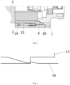
FIG. 1 is a schematic half sectional view of a mounting structure for a leaky cable connector according to the present application; -
FIG. 2 is a partial schematic enlarged view ofFIG. 1 ; -
FIG. 3 is a partial schematic diagram when a leaky cable and a mounting structure are assembled; and -
FIG. 4 is a schematic diagram of another mounting manner of a pressure ring and a shell. - Reference numerals:
1. first shell; 2. second shell; 3. leaky cable; 4. cable clamp; 5. assembly space; 6. protrusion; 7. gap; 8. first limiting member; 9. second limiting member; 10. jack socket; 11. central conductor; 12. riveting tube; 13. insulator; 14. first sealing member; 15. housing; 16. pressure ring; 17. annular groove; and 18. second sealing member. -
FIG. 1 to FIG. 3 show a specific embodiment of a mounting structure for a leaky cable connector, including afirst shell 1 and asecond shell 2 that are sleeved with each other in an axial direction. Thefirst shell 1 and thesecond shell 2 are assembled by interference fit. Thefirst shell 1 is disposed inside. Thesecond shell 2 is disposed outside. A mounting space allowing aleaky cable 3 to pass through is provided in each of thefirst shell 1 and thesecond shell 2. - A
cable clamp 4 is disposed at a connection between thefirst shell 1 and thesecond shell 2. An inner circumference of thefirst shell 1 is formed with anassembly space 5 allowing insertion of thecable clamp 4 under the action of an external force. Correspondingly, thecable clamp 4 is formed with aprotrusion 6 adapting to theassembly space 5, and extends in a direction of theassembly space 5 away from thefirst shell 1. Agap 7 allowing insertion of an external conductor of theleaky cable 3 is provided between a main body of thecable clamp 4 and thefirst shell 1. When noleaky cable 3 passes through the mounting spaces in thefirst shell 1 and thesecond shell 2, the other end of thecable clamp 4 opposite to theprotrusion 6 is provided with a step used as a first limitingmember 8, and thefirst shell 1 is provided with a bump used as a second limitingmember 9 matching the first limitingmember 8. Therefore, thecable clamp 4 is limited at a current position. When theleaky cable 3 and the mounting structure are assembled, that is, as theleaky cable 3 gradually passes through the mounting spaces in thesecond shell 2 and thefirst shell 1, the first limitingmember 8 climbs over the second limitingmember 9 under the action of an external force to insert theprotrusion 6 in theassembly space 5 for fastening, and at the same time thecable clamp 4 is subjected to a force to move toward thefirst shell 1 to fasten the external conductor of theleaky cable 3. - A plurality of channels are provided in the
cable clamp 4, and a barb is disposed on an inner wall of thecable clamp 4. When thecable clamp 4 is subjected to a force to fasten the external conductor of theleaky cable 3, the barb is clamped in an outer sheath of theleaky cable 3, thereby improving the stability of mounting. A stepped surface is provided on a side of the barb. During the mounting of theleaky cable 3, the stepped surface abuts against the outer sheath of theleaky cable 3, to limit a mounting size of theleaky cable 3. - Specifically, an end surface of the
cable clamp 4 facing thegap 7 is a tapered surface with an inner diameter gradually increasing from one end close to thesecond shell 2 to the other end close to thefirst shell 1, and an end surface of thefirst shell 1 facing thegap 7 is formed by two partial inclined surfaces. The two partial inclined surfaces form an arc-shaped surface protruding outward away from thegap 7. - A radial end surface of the
first shell 1 located in thesecond shell 2 contacts an end surface of a foaming layer of theleaky cable 3, to limit the movement of theleaky cable 3. An internal conductor is disposed in an axial direction in thefirst shell 1. The internal conductor includes ajack socket 10, a central conductor 11, and a riveting tube 12 that are sequentially disposed. A first step is disposed on one side of the central conductor 11 close to the riveting tube 12. A blind hole is provided at a central position. A through hole matching the first step is provided in the riveting tube 12. The blind hole is expanded to fasten the riveting tube 12 on the central conductor 11 in a riveting manner. The other side of the central conductor 11 close to thejack socket 10 is provided with a second step. The second step is provided with aninsulator 13, and thejack socket 10 and the central conductor 11 are fastened by interference fit. Thejack socket 10 further limits the axial movement of theinsulator 13. Theinsulator 13 matches thefirst shell 1, to fasten the internal conductor inside thefirst shell 1. - A third limiting member and a fourth limiting member are disposed at an interval in an axial direction in the
second shell 2. The third limiting member and the fourth limiting member are respectively stepped surfaces formed in the middle of thesecond shell 2 and at an end of thesecond shell 2 away from thefirst shell 1. A first sealing member 14, ahousing 15, and apressure ring 16 are sequentially disposed between the third limiting member and the fourth limiting member. Thepressure ring 16 abuts against the fourth limiting member, to position thepressure ring 16, and thepressure ring 16 is assembled with thesecond shell 2 by interference fit. The first sealing member 14 abuts against the third limiting member. Thehousing 15 abuts against both the first sealing member 14 and thepressure ring 16. Thepressure ring 16 limits that the first sealing member 14 and thehousing 15 can only move between the third limiting member and a left end of thepressure ring 16. It is avoided that thehousing 15 moves rightward in a free state to apply a force to thecable clamp 4, and as a result the gap between thecable clamp 4 and thefirst shell 1 is reduced to affect the insertion of the external conductor of theleaky cable 3. When moving in a direction away from thefirst shell 1, thehousing 15 presses the first sealing member 14 to implement sealing and waterproofing. - To further improve the stability of the connection, an end surface of the
cable clamp 4 away from the axis of thefirst shell 1 is also a tapered surface. Thehousing 15 is provided with a tapered surface matching thecable clamp 4, to apply a radial pressing force to thecable clamp 4 under the action of an external force, so that the diameter of thecable clamp 4 decreases, and the barb inside is clamped in the outer sheath of theleaky cable 3, to further lock theleaky cable 3. - To further improve the sealing and waterproof performance, an
annular groove 17 is provided in a contact surface between thefirst shell 1 and thesecond shell 2, and asecond sealing member 18 is disposed inside theannular groove 17. - Further provided is a leaky cable connector, including the mounting structure for a leaky cable connector.
- Before the
leaky cable 3 is assembled, the connector is preassembled to form a whole. Theleaky cable 3 requires foaming and coring. During mounting, the preparedleaky cable 3 is inserted in the connector from thesecond shell 2, until theleaky cable 3 abuts against thefirst shell 1 and can be no longer pushed. With the unique design of thefirst shell 1, thesecond shell 2, and thecable clamp 4, theleaky cable 3 may be smoothly inserted in the connector, and does not cause the movement of any part. After theleaky cable 3 is pushed to position, an assembly is placed in a dedicated fixture for press fit. With the press fit, the slotted position of thecable clamp 4 is pressed to deform, and the barb is clamped in the outer sheath of theleaky cable 3. The external conductor of theleaky cable 3 is pressed on the tapered surfaces of thecable clamp 4 and thefirst shell 1, to complete mounting. - In an alternative embodiment, end surfaces of the
cable clamp 4 and thefirst shell 1 facing thegap 7 may also be tapered surfaces. In this case, thecable clamp 4 and thefirst shell 1 form theannular gap 7. - In an alternative embodiment, as shown in
FIG. 4 , an end surface of thepressure ring 16 facing thehousing 15 is formed with a wedged surface. Correspondingly, an end surface of thehousing 15 facing thepressure ring 16 is formed with a wedged protrusion adapting to the wedged surface, so that a limiting function can be implemented.
Claims (8)
- A mounting structure for a leaky cable connector, comprising:a first shell (1) and a second shell (2) that are sleeved with each other, wherein the first shell (1) is disposed inside, the second shell (2) is disposed outside, and a mounting space allowing a leaky cable (3) to pass through is provided in each of the first shell (1) and the second shell (2); anda cable clamp (4), disposed at a connection between the first shell (1) and the second shell (2), wherein a gap (7) allowing insertion of an external conductor of the leaky cable (3) is provided between the cable clamp (4) and the first shell (1), and when the leaky cable (3) is inserted in the mounting spaces, the cable clamp (4) is subjected to a force to move toward the first shell (1) to fasten the external conductor of the leaky cable (3),characterized in that thefirst shell (1) is formed with an assembly space (5) allowing insertion of the cable clamp (4) under the action of an external force, and correspondingly, the cable clamp (4) is formed with a protrusion (6) adapting to the assembly space (5),and in that the other end of the cable clamp (4) opposite to the protrusion (6) is provided with a first limiting member (8), the first shell (1) is provided with a second limiting member (9) matching the first limiting member (8), and the first limiting member (8) climbs over the second limiting member (9) under the action of an external force to insert the protrusion (6) into the assembly space (5) for fastening.
- The mounting structure for a leaky cable connector according to claim 1, wherein an end surface of at least one of the cable clamp (4) or the first shell (1) facing the gap (7) is a tapered surface.
- The mounting structure for a leaky cable connector according to claim 2, wherein an end surface of the cable clamp (4) facing the gap (7) is a tapered surface with an inner diameter gradually increasing from one end close to the second shell (2) to the other end close to the first shell (1), and an end surface of the first shell (1) facing the gap (7) is formed by at least two partial inclined surfaces.
- The mounting structure for a leaky cable connector according to any one of claims 1 to 3, wherein a third limiting member and a fourth limiting member are disposed at an interval in an axial direction in the second shell (2), a first sealing member (14), a housing (15), and a pressure ring (16) are sequentially disposed between the third limiting member and the fourth limiting member, the pressure ring (16) abuts against the fourth limiting member, the first sealing member (14) abuts against the third limiting member, and the housing (15) abuts against both the first sealing member (14) and the pressure ring (16).
- The mounting structure for a leaky cable connector according to claim 4, wherein the housing (15) is provided with a tapered surface matching the cable clamp (4) to apply a radial pressing force to the cable clamp (4) under the action of an external force.
- The mounting structure for a leaky cable connector according to any one of claims 1 to 5, wherein an annular groove (17) is provided in a contact surface between the first shell (1) and the second shell (2), and a second sealing member (18) is disposed inside the annular groove (17).
- The mounting structure for a leaky cable connector according to any one of claims 1 to 6, wherein the first shell (1) and the second shell (2) are assembled by interference fit.
- A leaky cable connector, comprising the mounting structure for a leaky cable connector according to any one of claims 1 to7.
Applications Claiming Priority (2)
| Application Number | Priority Date | Filing Date | Title |
|---|---|---|---|
| CN202011037583.7A CN112201977B (en) | 2020-09-27 | 2020-09-27 | Mounting structure of cable leakage connector and cable leakage connector |
| PCT/CN2021/092288 WO2022062418A1 (en) | 2020-09-27 | 2021-05-08 | Installation structure of leaky cable connector, and leaky cable connector |
Publications (3)
| Publication Number | Publication Date |
|---|---|
| EP4007078A1 EP4007078A1 (en) | 2022-06-01 |
| EP4007078A4 EP4007078A4 (en) | 2022-12-07 |
| EP4007078B1 true EP4007078B1 (en) | 2025-02-12 |
Family
ID=74007055
Family Applications (1)
| Application Number | Title | Priority Date | Filing Date |
|---|---|---|---|
| EP21857011.7A Active EP4007078B1 (en) | 2020-09-27 | 2021-05-08 | Installation structure of leaky cable connector, and leaky cable connector |
Country Status (4)
| Country | Link |
|---|---|
| EP (1) | EP4007078B1 (en) |
| CN (1) | CN112201977B (en) |
| ES (1) | ES3012662T3 (en) |
| WO (1) | WO2022062418A1 (en) |
Families Citing this family (3)
| Publication number | Priority date | Publication date | Assignee | Title |
|---|---|---|---|---|
| CN112201977B (en) * | 2020-09-27 | 2022-04-26 | 中天射频电缆有限公司 | Mounting structure of cable leakage connector and cable leakage connector |
| CN114221166B (en) * | 2021-12-23 | 2024-01-30 | 杭州摩光通讯器材有限公司 | Connector with fast-assembling structure for radio frequency coaxial leaky cable |
| CN116706601A (en) * | 2023-06-16 | 2023-09-05 | 珠海汉胜科技股份有限公司 | A High Stability RF Connector for Leaky Cable Connection |
Family Cites Families (13)
| Publication number | Priority date | Publication date | Assignee | Title |
|---|---|---|---|---|
| US5938465A (en) * | 1997-10-15 | 1999-08-17 | Palco Connector, Inc. | Machined dual spring ring connector for coaxial cable |
| DE19944491C2 (en) * | 1999-09-16 | 2003-12-18 | Spinner Gmbh Elektrotech | Connector for radiating coaxial cable |
| US6884113B1 (en) * | 2003-10-15 | 2005-04-26 | John Mezzalingua Associates, Inc. | Apparatus for making permanent hardline connection |
| US7261581B2 (en) * | 2003-12-01 | 2007-08-28 | Corning Gilbert Inc. | Coaxial connector and method |
| CN100502148C (en) * | 2007-04-28 | 2009-06-17 | 罗森伯格亚太电子有限公司 | A coaxial cable connector |
| CN100502149C (en) * | 2007-06-28 | 2009-06-17 | 罗森伯格亚太电子有限公司 | A coaxial cable connector |
| US7934954B1 (en) * | 2010-04-02 | 2011-05-03 | John Mezzalingua Associates, Inc. | Coaxial cable compression connectors |
| CN101841108B (en) * | 2010-05-06 | 2011-09-14 | 镇江市正恺电子有限公司 | Double wedge type radio frequency connector |
| CN202034650U (en) * | 2011-04-15 | 2011-11-09 | 江苏正恺电子科技有限公司 | Connector for coaxial leaky cable |
| JP5422617B2 (en) * | 2011-08-10 | 2014-02-19 | 株式会社フジクラ | Coaxial cable connector mounting tool |
| CN104362480A (en) * | 2014-11-11 | 2015-02-18 | 镇江华浩通信器材有限公司 | Universal connector for 7/8 common cables and 7/8 leaky cables |
| CN209675526U (en) * | 2019-04-01 | 2019-11-22 | 中航富士达科技股份有限公司 | A kind of quick attaching connector being adapted to corrugated cable |
| CN112201977B (en) * | 2020-09-27 | 2022-04-26 | 中天射频电缆有限公司 | Mounting structure of cable leakage connector and cable leakage connector |
-
2020
- 2020-09-27 CN CN202011037583.7A patent/CN112201977B/en active Active
-
2021
- 2021-05-08 EP EP21857011.7A patent/EP4007078B1/en active Active
- 2021-05-08 ES ES21857011T patent/ES3012662T3/en active Active
- 2021-05-08 WO PCT/CN2021/092288 patent/WO2022062418A1/en not_active Ceased
Also Published As
| Publication number | Publication date |
|---|---|
| WO2022062418A1 (en) | 2022-03-31 |
| CN112201977A (en) | 2021-01-08 |
| EP4007078A4 (en) | 2022-12-07 |
| CN112201977B (en) | 2022-04-26 |
| EP4007078A1 (en) | 2022-06-01 |
| ES3012662T3 (en) | 2025-04-09 |
Similar Documents
| Publication | Publication Date | Title |
|---|---|---|
| US3910673A (en) | Coaxial cable connectors | |
| US8366482B2 (en) | Re-enterable hardline coaxial cable connector | |
| US6634906B1 (en) | Coaxial connector | |
| CN101820109B (en) | Connector with positive stop for coaxial cable and associated methods | |
| US7182639B2 (en) | Coaxial cable connector | |
| EP1779470B1 (en) | Compression connector for coaxial cable | |
| US7189115B1 (en) | Connector for spiral corrugated coaxial cable and method of use thereof | |
| EP3329554B1 (en) | Cable connector | |
| US10958022B2 (en) | Radio-frequency coaxial cable connector with quick installation | |
| EP4007078A1 (en) | Installation structure of leaky cable connector, and leaky cable connector | |
| US20110059648A1 (en) | Audio Jack Connector Device | |
| AU2020101289A4 (en) | Quickly-demountable highly-reliable radio frequency coaxial connector | |
| US7160149B1 (en) | Coaxial connector and method of connecting a two-wire cable to a coaxial connector | |
| US10601174B2 (en) | Electrical connector assembly with a locking device to stabilize the electrical connection | |
| US7059900B2 (en) | Coaxial cable splice connector assemblies | |
| US7727015B2 (en) | Bulge-type coaxial cable connector | |
| CN114221166B (en) | Connector with fast-assembling structure for radio frequency coaxial leaky cable | |
| EP4583325A1 (en) | Radio frequency coaxial connector | |
| CN111900572A (en) | Radio frequency connector matched with ultra-flexible threaded cable for multiple waterproof intermodulation stabilization | |
| RU2794449C1 (en) | Mounting structure for transmitting cable connector and transmitting cable connector | |
| JP3410721B2 (en) | Terminal connector for coaxial cable | |
| US9293868B2 (en) | Attachment ring for attaching a shield of a cable to a shell | |
| CN219268074U (en) | Radio frequency coaxial connector | |
| US12470013B2 (en) | Electrical terminal connector with rotatable mounting features | |
| CN223093258U (en) | Radio frequency coaxial hole head connector |
Legal Events
| Date | Code | Title | Description |
|---|---|---|---|
| STAA | Information on the status of an ep patent application or granted ep patent |
Free format text: STATUS: UNKNOWN |
|
| STAA | Information on the status of an ep patent application or granted ep patent |
Free format text: STATUS: THE INTERNATIONAL PUBLICATION HAS BEEN MADE |
|
| PUAI | Public reference made under article 153(3) epc to a published international application that has entered the european phase |
Free format text: ORIGINAL CODE: 0009012 |
|
| STAA | Information on the status of an ep patent application or granted ep patent |
Free format text: STATUS: REQUEST FOR EXAMINATION WAS MADE |
|
| 17P | Request for examination filed |
Effective date: 20220225 |
|
| AK | Designated contracting states |
Kind code of ref document: A1 Designated state(s): AL AT BE BG CH CY CZ DE DK EE ES FI FR GB GR HR HU IE IS IT LI LT LU LV MC MK MT NL NO PL PT RO RS SE SI SK SM TR |
|
| REG | Reference to a national code |
Ref country code: DE Ref legal event code: R079 Free format text: PREVIOUS MAIN CLASS: H01R0013020000 Ipc: H01R0009050000 Ref document number: 602021026164 Country of ref document: DE |
|
| A4 | Supplementary search report drawn up and despatched |
Effective date: 20221104 |
|
| RIC1 | Information provided on ipc code assigned before grant |
Ipc: H01R 4/70 20060101ALI20221028BHEP Ipc: H01R 24/56 20110101ALI20221028BHEP Ipc: H01R 9/05 20060101AFI20221028BHEP |
|
| DAV | Request for validation of the european patent (deleted) | ||
| DAX | Request for extension of the european patent (deleted) | ||
| GRAP | Despatch of communication of intention to grant a patent |
Free format text: ORIGINAL CODE: EPIDOSNIGR1 |
|
| STAA | Information on the status of an ep patent application or granted ep patent |
Free format text: STATUS: GRANT OF PATENT IS INTENDED |
|
| INTG | Intention to grant announced |
Effective date: 20241112 |
|
| GRAS | Grant fee paid |
Free format text: ORIGINAL CODE: EPIDOSNIGR3 |
|
| GRAA | (expected) grant |
Free format text: ORIGINAL CODE: 0009210 |
|
| STAA | Information on the status of an ep patent application or granted ep patent |
Free format text: STATUS: THE PATENT HAS BEEN GRANTED |
|
| AK | Designated contracting states |
Kind code of ref document: B1 Designated state(s): AL AT BE BG CH CY CZ DE DK EE ES FI FR GB GR HR HU IE IS IT LI LT LU LV MC MK MT NL NO PL PT RO RS SE SI SK SM TR |
|
| REG | Reference to a national code |
Ref country code: GB Ref legal event code: FG4D |
|
| REG | Reference to a national code |
Ref country code: CH Ref legal event code: EP |
|
| REG | Reference to a national code |
Ref country code: DE Ref legal event code: R096 Ref document number: 602021026164 Country of ref document: DE |
|
| REG | Reference to a national code |
Ref country code: IE Ref legal event code: FG4D |
|
| REG | Reference to a national code |
Ref country code: ES Ref legal event code: FG2A Ref document number: 3012662 Country of ref document: ES Kind code of ref document: T3 Effective date: 20250409 |
|
| REG | Reference to a national code |
Ref country code: NL Ref legal event code: MP Effective date: 20250212 |
|
| PG25 | Lapsed in a contracting state [announced via postgrant information from national office to epo] |
Ref country code: RS Free format text: LAPSE BECAUSE OF FAILURE TO SUBMIT A TRANSLATION OF THE DESCRIPTION OR TO PAY THE FEE WITHIN THE PRESCRIBED TIME-LIMIT Effective date: 20250512 |
|
| PG25 | Lapsed in a contracting state [announced via postgrant information from national office to epo] |
Ref country code: FI Free format text: LAPSE BECAUSE OF FAILURE TO SUBMIT A TRANSLATION OF THE DESCRIPTION OR TO PAY THE FEE WITHIN THE PRESCRIBED TIME-LIMIT Effective date: 20250212 |
|
| PG25 | Lapsed in a contracting state [announced via postgrant information from national office to epo] |
Ref country code: PL Free format text: LAPSE BECAUSE OF FAILURE TO SUBMIT A TRANSLATION OF THE DESCRIPTION OR TO PAY THE FEE WITHIN THE PRESCRIBED TIME-LIMIT Effective date: 20250212 |
|
| REG | Reference to a national code |
Ref country code: LT Ref legal event code: MG9D |
|
| PG25 | Lapsed in a contracting state [announced via postgrant information from national office to epo] |
Ref country code: NO Free format text: LAPSE BECAUSE OF FAILURE TO SUBMIT A TRANSLATION OF THE DESCRIPTION OR TO PAY THE FEE WITHIN THE PRESCRIBED TIME-LIMIT Effective date: 20250512 Ref country code: IS Free format text: LAPSE BECAUSE OF FAILURE TO SUBMIT A TRANSLATION OF THE DESCRIPTION OR TO PAY THE FEE WITHIN THE PRESCRIBED TIME-LIMIT Effective date: 20250612 |
|
| PG25 | Lapsed in a contracting state [announced via postgrant information from national office to epo] |
Ref country code: NL Free format text: LAPSE BECAUSE OF FAILURE TO SUBMIT A TRANSLATION OF THE DESCRIPTION OR TO PAY THE FEE WITHIN THE PRESCRIBED TIME-LIMIT Effective date: 20250212 |
|
| PG25 | Lapsed in a contracting state [announced via postgrant information from national office to epo] |
Ref country code: HR Free format text: LAPSE BECAUSE OF FAILURE TO SUBMIT A TRANSLATION OF THE DESCRIPTION OR TO PAY THE FEE WITHIN THE PRESCRIBED TIME-LIMIT Effective date: 20250212 |
|
| PG25 | Lapsed in a contracting state [announced via postgrant information from national office to epo] |
Ref country code: LV Free format text: LAPSE BECAUSE OF FAILURE TO SUBMIT A TRANSLATION OF THE DESCRIPTION OR TO PAY THE FEE WITHIN THE PRESCRIBED TIME-LIMIT Effective date: 20250212 Ref country code: PT Free format text: LAPSE BECAUSE OF FAILURE TO SUBMIT A TRANSLATION OF THE DESCRIPTION OR TO PAY THE FEE WITHIN THE PRESCRIBED TIME-LIMIT Effective date: 20250612 |
|
| PG25 | Lapsed in a contracting state [announced via postgrant information from national office to epo] |
Ref country code: BG Free format text: LAPSE BECAUSE OF FAILURE TO SUBMIT A TRANSLATION OF THE DESCRIPTION OR TO PAY THE FEE WITHIN THE PRESCRIBED TIME-LIMIT Effective date: 20250212 |
|
| REG | Reference to a national code |
Ref country code: AT Ref legal event code: MK05 Ref document number: 1767022 Country of ref document: AT Kind code of ref document: T Effective date: 20250212 |
|
| PG25 | Lapsed in a contracting state [announced via postgrant information from national office to epo] |
Ref country code: SE Free format text: LAPSE BECAUSE OF FAILURE TO SUBMIT A TRANSLATION OF THE DESCRIPTION OR TO PAY THE FEE WITHIN THE PRESCRIBED TIME-LIMIT Effective date: 20250212 |
|
| PG25 | Lapsed in a contracting state [announced via postgrant information from national office to epo] |
Ref country code: SM Free format text: LAPSE BECAUSE OF FAILURE TO SUBMIT A TRANSLATION OF THE DESCRIPTION OR TO PAY THE FEE WITHIN THE PRESCRIBED TIME-LIMIT Effective date: 20250212 |
|
| PG25 | Lapsed in a contracting state [announced via postgrant information from national office to epo] |
Ref country code: DK Free format text: LAPSE BECAUSE OF FAILURE TO SUBMIT A TRANSLATION OF THE DESCRIPTION OR TO PAY THE FEE WITHIN THE PRESCRIBED TIME-LIMIT Effective date: 20250212 |
|
| PG25 | Lapsed in a contracting state [announced via postgrant information from national office to epo] |
Ref country code: AT Free format text: LAPSE BECAUSE OF FAILURE TO SUBMIT A TRANSLATION OF THE DESCRIPTION OR TO PAY THE FEE WITHIN THE PRESCRIBED TIME-LIMIT Effective date: 20250212 |
|
| PG25 | Lapsed in a contracting state [announced via postgrant information from national office to epo] |
Ref country code: CZ Free format text: LAPSE BECAUSE OF FAILURE TO SUBMIT A TRANSLATION OF THE DESCRIPTION OR TO PAY THE FEE WITHIN THE PRESCRIBED TIME-LIMIT Effective date: 20250212 Ref country code: EE Free format text: LAPSE BECAUSE OF FAILURE TO SUBMIT A TRANSLATION OF THE DESCRIPTION OR TO PAY THE FEE WITHIN THE PRESCRIBED TIME-LIMIT Effective date: 20250212 |
|
| PG25 | Lapsed in a contracting state [announced via postgrant information from national office to epo] |
Ref country code: RO Free format text: LAPSE BECAUSE OF FAILURE TO SUBMIT A TRANSLATION OF THE DESCRIPTION OR TO PAY THE FEE WITHIN THE PRESCRIBED TIME-LIMIT Effective date: 20250212 |
|
| PG25 | Lapsed in a contracting state [announced via postgrant information from national office to epo] |
Ref country code: SK Free format text: LAPSE BECAUSE OF FAILURE TO SUBMIT A TRANSLATION OF THE DESCRIPTION OR TO PAY THE FEE WITHIN THE PRESCRIBED TIME-LIMIT Effective date: 20250212 |
|
| REG | Reference to a national code |
Ref country code: DE Ref legal event code: R097 Ref document number: 602021026164 Country of ref document: DE |
|
| PLBE | No opposition filed within time limit |
Free format text: ORIGINAL CODE: 0009261 |
|
| STAA | Information on the status of an ep patent application or granted ep patent |
Free format text: STATUS: NO OPPOSITION FILED WITHIN TIME LIMIT |
|
| REG | Reference to a national code |
Ref country code: CH Ref legal event code: H13 Free format text: ST27 STATUS EVENT CODE: U-0-0-H10-H13 (AS PROVIDED BY THE NATIONAL OFFICE) Effective date: 20251223 |
|
| REG | Reference to a national code |
Ref country code: CH Ref legal event code: L10 Free format text: ST27 STATUS EVENT CODE: U-0-0-L10-L00 (AS PROVIDED BY THE NATIONAL OFFICE) Effective date: 20251224 |
|
| PG25 | Lapsed in a contracting state [announced via postgrant information from national office to epo] |
Ref country code: LU Free format text: LAPSE BECAUSE OF NON-PAYMENT OF DUE FEES Effective date: 20250508 |
|
| PG25 | Lapsed in a contracting state [announced via postgrant information from national office to epo] |
Ref country code: CH Free format text: LAPSE BECAUSE OF NON-PAYMENT OF DUE FEES Effective date: 20250531 |
|
| 26N | No opposition filed |
Effective date: 20251113 |
|
| GBPC | Gb: european patent ceased through non-payment of renewal fee |
Effective date: 20250512 |
|
| REG | Reference to a national code |
Ref country code: BE Ref legal event code: MM Effective date: 20250531 |
|
| PG25 | Lapsed in a contracting state [announced via postgrant information from national office to epo] |
Ref country code: MC Free format text: LAPSE BECAUSE OF FAILURE TO SUBMIT A TRANSLATION OF THE DESCRIPTION OR TO PAY THE FEE WITHIN THE PRESCRIBED TIME-LIMIT Effective date: 20250212 |
|
| PG25 | Lapsed in a contracting state [announced via postgrant information from national office to epo] |
Ref country code: GB Free format text: LAPSE BECAUSE OF NON-PAYMENT OF DUE FEES Effective date: 20250512 |
|
| PG25 | Lapsed in a contracting state [announced via postgrant information from national office to epo] |
Ref country code: IE Free format text: LAPSE BECAUSE OF NON-PAYMENT OF DUE FEES Effective date: 20250508 |
|
| PG25 | Lapsed in a contracting state [announced via postgrant information from national office to epo] |
Ref country code: BE Free format text: LAPSE BECAUSE OF NON-PAYMENT OF DUE FEES Effective date: 20250531 |
|
| PG25 | Lapsed in a contracting state [announced via postgrant information from national office to epo] |
Ref country code: FR Free format text: LAPSE BECAUSE OF NON-PAYMENT OF DUE FEES Effective date: 20250531 |
|
| PG25 | Lapsed in a contracting state [announced via postgrant information from national office to epo] |
Ref country code: LT Free format text: LAPSE BECAUSE OF FAILURE TO SUBMIT A TRANSLATION OF THE DESCRIPTION OR TO PAY THE FEE WITHIN THE PRESCRIBED TIME-LIMIT Effective date: 20250212 |
|
| PGFP | Annual fee paid to national office [announced via postgrant information from national office to epo] |
Ref country code: ES Payment date: 20260608 Year of fee payment: 6 |
|
| PGFP | Annual fee paid to national office [announced via postgrant information from national office to epo] |
Ref country code: IT Payment date: 20260507 Year of fee payment: 6 |
|
| PGFP | Annual fee paid to national office [announced via postgrant information from national office to epo] |
Ref country code: DE Payment date: 20260513 Year of fee payment: 6 |
|
| PG25 | Lapsed in a contracting state [announced via postgrant information from national office to epo] |
Ref country code: GR Free format text: LAPSE BECAUSE OF NON-PAYMENT OF DUE FEES Effective date: 20250531 |
|
| PG25 | Lapsed in a contracting state [announced via postgrant information from national office to epo] |
Ref country code: CY Free format text: LAPSE BECAUSE OF FAILURE TO SUBMIT A TRANSLATION OF THE DESCRIPTION OR TO PAY THE FEE WITHIN THE PRESCRIBED TIME-LIMIT Effective date: 20250212 |