EP4007059A1 - Battery pack - Google Patents
Battery pack Download PDFInfo
- Publication number
- EP4007059A1 EP4007059A1 EP21209873.5A EP21209873A EP4007059A1 EP 4007059 A1 EP4007059 A1 EP 4007059A1 EP 21209873 A EP21209873 A EP 21209873A EP 4007059 A1 EP4007059 A1 EP 4007059A1
- Authority
- EP
- European Patent Office
- Prior art keywords
- busbar
- insulation film
- battery pack
- flexible substrate
- sub
- Prior art date
- Legal status (The legal status is an assumption and is not a legal conclusion. Google has not performed a legal analysis and makes no representation as to the accuracy of the status listed.)
- Pending
Links
Images




Classifications
-
- H—ELECTRICITY
- H01—ELECTRIC ELEMENTS
- H01M—PROCESSES OR MEANS, e.g. BATTERIES, FOR THE DIRECT CONVERSION OF CHEMICAL ENERGY INTO ELECTRICAL ENERGY
- H01M50/00—Constructional details or processes of manufacture of the non-active parts of electrochemical cells other than fuel cells, e.g. hybrid cells
- H01M50/50—Current conducting connections for cells or batteries
- H01M50/502—Interconnectors for connecting terminals of adjacent batteries; Interconnectors for connecting cells outside a battery casing
- H01M50/521—Interconnectors for connecting terminals of adjacent batteries; Interconnectors for connecting cells outside a battery casing characterised by the material
- H01M50/526—Interconnectors for connecting terminals of adjacent batteries; Interconnectors for connecting cells outside a battery casing characterised by the material having a layered structure
-
- H—ELECTRICITY
- H01—ELECTRIC ELEMENTS
- H01M—PROCESSES OR MEANS, e.g. BATTERIES, FOR THE DIRECT CONVERSION OF CHEMICAL ENERGY INTO ELECTRICAL ENERGY
- H01M50/00—Constructional details or processes of manufacture of the non-active parts of electrochemical cells other than fuel cells, e.g. hybrid cells
- H01M50/50—Current conducting connections for cells or batteries
- H01M50/502—Interconnectors for connecting terminals of adjacent batteries; Interconnectors for connecting cells outside a battery casing
-
- H—ELECTRICITY
- H01—ELECTRIC ELEMENTS
- H01M—PROCESSES OR MEANS, e.g. BATTERIES, FOR THE DIRECT CONVERSION OF CHEMICAL ENERGY INTO ELECTRICAL ENERGY
- H01M50/00—Constructional details or processes of manufacture of the non-active parts of electrochemical cells other than fuel cells, e.g. hybrid cells
- H01M50/50—Current conducting connections for cells or batteries
- H01M50/502—Interconnectors for connecting terminals of adjacent batteries; Interconnectors for connecting cells outside a battery casing
- H01M50/507—Interconnectors for connecting terminals of adjacent batteries; Interconnectors for connecting cells outside a battery casing comprising an arrangement of two or more busbars within a container structure, e.g. busbar modules
-
- H—ELECTRICITY
- H01—ELECTRIC ELEMENTS
- H01M—PROCESSES OR MEANS, e.g. BATTERIES, FOR THE DIRECT CONVERSION OF CHEMICAL ENERGY INTO ELECTRICAL ENERGY
- H01M10/00—Secondary cells; Manufacture thereof
- H01M10/42—Methods or arrangements for servicing or maintenance of secondary cells or secondary half-cells
- H01M10/425—Structural combination with electronic components, e.g. electronic circuits integrated to the outside of the casing
-
- H—ELECTRICITY
- H01—ELECTRIC ELEMENTS
- H01M—PROCESSES OR MEANS, e.g. BATTERIES, FOR THE DIRECT CONVERSION OF CHEMICAL ENERGY INTO ELECTRICAL ENERGY
- H01M10/00—Secondary cells; Manufacture thereof
- H01M10/42—Methods or arrangements for servicing or maintenance of secondary cells or secondary half-cells
- H01M10/425—Structural combination with electronic components, e.g. electronic circuits integrated to the outside of the casing
- H01M10/4257—Smart batteries, e.g. electronic circuits inside the housing of the cells or batteries
-
- H—ELECTRICITY
- H01—ELECTRIC ELEMENTS
- H01M—PROCESSES OR MEANS, e.g. BATTERIES, FOR THE DIRECT CONVERSION OF CHEMICAL ENERGY INTO ELECTRICAL ENERGY
- H01M10/00—Secondary cells; Manufacture thereof
- H01M10/42—Methods or arrangements for servicing or maintenance of secondary cells or secondary half-cells
- H01M10/48—Accumulators combined with arrangements for measuring, testing or indicating the condition of cells, e.g. the level or density of the electrolyte
- H01M10/482—Accumulators combined with arrangements for measuring, testing or indicating the condition of cells, e.g. the level or density of the electrolyte for several batteries or cells simultaneously or sequentially
-
- H—ELECTRICITY
- H01—ELECTRIC ELEMENTS
- H01M—PROCESSES OR MEANS, e.g. BATTERIES, FOR THE DIRECT CONVERSION OF CHEMICAL ENERGY INTO ELECTRICAL ENERGY
- H01M10/00—Secondary cells; Manufacture thereof
- H01M10/42—Methods or arrangements for servicing or maintenance of secondary cells or secondary half-cells
- H01M10/48—Accumulators combined with arrangements for measuring, testing or indicating the condition of cells, e.g. the level or density of the electrolyte
- H01M10/486—Accumulators combined with arrangements for measuring, testing or indicating the condition of cells, e.g. the level or density of the electrolyte for measuring temperature
-
- H—ELECTRICITY
- H01—ELECTRIC ELEMENTS
- H01M—PROCESSES OR MEANS, e.g. BATTERIES, FOR THE DIRECT CONVERSION OF CHEMICAL ENERGY INTO ELECTRICAL ENERGY
- H01M50/00—Constructional details or processes of manufacture of the non-active parts of electrochemical cells other than fuel cells, e.g. hybrid cells
- H01M50/20—Mountings; Secondary casings or frames; Racks, modules or packs; Suspension devices; Shock absorbers; Transport or carrying devices; Holders
-
- H—ELECTRICITY
- H01—ELECTRIC ELEMENTS
- H01M—PROCESSES OR MEANS, e.g. BATTERIES, FOR THE DIRECT CONVERSION OF CHEMICAL ENERGY INTO ELECTRICAL ENERGY
- H01M50/00—Constructional details or processes of manufacture of the non-active parts of electrochemical cells other than fuel cells, e.g. hybrid cells
- H01M50/20—Mountings; Secondary casings or frames; Racks, modules or packs; Suspension devices; Shock absorbers; Transport or carrying devices; Holders
- H01M50/289—Mountings; Secondary casings or frames; Racks, modules or packs; Suspension devices; Shock absorbers; Transport or carrying devices; Holders characterised by spacing elements or positioning means within frames, racks or packs
- H01M50/293—Mountings; Secondary casings or frames; Racks, modules or packs; Suspension devices; Shock absorbers; Transport or carrying devices; Holders characterised by spacing elements or positioning means within frames, racks or packs characterised by the material
-
- H—ELECTRICITY
- H01—ELECTRIC ELEMENTS
- H01M—PROCESSES OR MEANS, e.g. BATTERIES, FOR THE DIRECT CONVERSION OF CHEMICAL ENERGY INTO ELECTRICAL ENERGY
- H01M50/00—Constructional details or processes of manufacture of the non-active parts of electrochemical cells other than fuel cells, e.g. hybrid cells
- H01M50/50—Current conducting connections for cells or batteries
- H01M50/502—Interconnectors for connecting terminals of adjacent batteries; Interconnectors for connecting cells outside a battery casing
- H01M50/503—Interconnectors for connecting terminals of adjacent batteries; Interconnectors for connecting cells outside a battery casing characterised by the shape of the interconnectors
-
- H—ELECTRICITY
- H01—ELECTRIC ELEMENTS
- H01M—PROCESSES OR MEANS, e.g. BATTERIES, FOR THE DIRECT CONVERSION OF CHEMICAL ENERGY INTO ELECTRICAL ENERGY
- H01M50/00—Constructional details or processes of manufacture of the non-active parts of electrochemical cells other than fuel cells, e.g. hybrid cells
- H01M50/50—Current conducting connections for cells or batteries
- H01M50/502—Interconnectors for connecting terminals of adjacent batteries; Interconnectors for connecting cells outside a battery casing
- H01M50/505—Interconnectors for connecting terminals of adjacent batteries; Interconnectors for connecting cells outside a battery casing comprising a single busbar
-
- H—ELECTRICITY
- H01—ELECTRIC ELEMENTS
- H01M—PROCESSES OR MEANS, e.g. BATTERIES, FOR THE DIRECT CONVERSION OF CHEMICAL ENERGY INTO ELECTRICAL ENERGY
- H01M50/00—Constructional details or processes of manufacture of the non-active parts of electrochemical cells other than fuel cells, e.g. hybrid cells
- H01M50/50—Current conducting connections for cells or batteries
- H01M50/502—Interconnectors for connecting terminals of adjacent batteries; Interconnectors for connecting cells outside a battery casing
- H01M50/519—Interconnectors for connecting terminals of adjacent batteries; Interconnectors for connecting cells outside a battery casing comprising printed circuit boards [PCB]
-
- H—ELECTRICITY
- H01—ELECTRIC ELEMENTS
- H01M—PROCESSES OR MEANS, e.g. BATTERIES, FOR THE DIRECT CONVERSION OF CHEMICAL ENERGY INTO ELECTRICAL ENERGY
- H01M50/00—Constructional details or processes of manufacture of the non-active parts of electrochemical cells other than fuel cells, e.g. hybrid cells
- H01M50/50—Current conducting connections for cells or batteries
- H01M50/569—Constructional details of current conducting connections for detecting conditions inside cells or batteries, e.g. details of voltage sensing terminals
-
- H—ELECTRICITY
- H01—ELECTRIC ELEMENTS
- H01M—PROCESSES OR MEANS, e.g. BATTERIES, FOR THE DIRECT CONVERSION OF CHEMICAL ENERGY INTO ELECTRICAL ENERGY
- H01M50/00—Constructional details or processes of manufacture of the non-active parts of electrochemical cells other than fuel cells, e.g. hybrid cells
- H01M50/50—Current conducting connections for cells or batteries
- H01M50/572—Means for preventing undesired use or discharge
- H01M50/584—Means for preventing undesired use or discharge for preventing incorrect connections inside or outside the batteries
- H01M50/59—Means for preventing undesired use or discharge for preventing incorrect connections inside or outside the batteries characterised by the protection means
- H01M50/595—Tapes
-
- H—ELECTRICITY
- H02—GENERATION; CONVERSION OR DISTRIBUTION OF ELECTRIC POWER
- H02G—INSTALLATION OF ELECTRIC CABLES OR LINES, OR OF COMBINED OPTICAL AND ELECTRIC CABLES OR LINES
- H02G5/00—Installations of bus-bars
- H02G5/005—Laminated bus-bars
-
- H—ELECTRICITY
- H05—ELECTRIC TECHNIQUES NOT OTHERWISE PROVIDED FOR
- H05K—PRINTED CIRCUITS; CASINGS OR CONSTRUCTIONAL DETAILS OF ELECTRIC APPARATUS; MANUFACTURE OF ASSEMBLAGES OF ELECTRICAL COMPONENTS
- H05K1/00—Printed circuits
- H05K1/02—Details
- H05K1/0213—Electrical arrangements not otherwise provided for
- H05K1/0263—High current adaptations, e.g. printed high current conductors or using auxiliary non-printed means; Fine and coarse circuit patterns on one circuit board
- H05K1/0265—High current adaptations, e.g. printed high current conductors or using auxiliary non-printed means; Fine and coarse circuit patterns on one circuit board characterized by the lay-out of or details of the printed conductors, e.g. reinforced conductors, redundant conductors, conductors having different cross-sections
-
- H—ELECTRICITY
- H01—ELECTRIC ELEMENTS
- H01M—PROCESSES OR MEANS, e.g. BATTERIES, FOR THE DIRECT CONVERSION OF CHEMICAL ENERGY INTO ELECTRICAL ENERGY
- H01M10/00—Secondary cells; Manufacture thereof
- H01M10/42—Methods or arrangements for servicing or maintenance of secondary cells or secondary half-cells
- H01M10/425—Structural combination with electronic components, e.g. electronic circuits integrated to the outside of the casing
- H01M2010/4271—Battery management systems including electronic circuits, e.g. control of current or voltage to keep battery in healthy state, cell balancing
-
- H—ELECTRICITY
- H01—ELECTRIC ELEMENTS
- H01M—PROCESSES OR MEANS, e.g. BATTERIES, FOR THE DIRECT CONVERSION OF CHEMICAL ENERGY INTO ELECTRICAL ENERGY
- H01M2220/00—Batteries for particular applications
- H01M2220/10—Batteries in stationary systems, e.g. emergency power source in plant
-
- H—ELECTRICITY
- H01—ELECTRIC ELEMENTS
- H01M—PROCESSES OR MEANS, e.g. BATTERIES, FOR THE DIRECT CONVERSION OF CHEMICAL ENERGY INTO ELECTRICAL ENERGY
- H01M50/00—Constructional details or processes of manufacture of the non-active parts of electrochemical cells other than fuel cells, e.g. hybrid cells
- H01M50/20—Mountings; Secondary casings or frames; Racks, modules or packs; Suspension devices; Shock absorbers; Transport or carrying devices; Holders
- H01M50/204—Racks, modules or packs for multiple batteries or multiple cells
- H01M50/207—Racks, modules or packs for multiple batteries or multiple cells characterised by their shape
- H01M50/209—Racks, modules or packs for multiple batteries or multiple cells characterised by their shape adapted for prismatic or rectangular cells
-
- H—ELECTRICITY
- H01—ELECTRIC ELEMENTS
- H01M—PROCESSES OR MEANS, e.g. BATTERIES, FOR THE DIRECT CONVERSION OF CHEMICAL ENERGY INTO ELECTRICAL ENERGY
- H01M50/00—Constructional details or processes of manufacture of the non-active parts of electrochemical cells other than fuel cells, e.g. hybrid cells
- H01M50/20—Mountings; Secondary casings or frames; Racks, modules or packs; Suspension devices; Shock absorbers; Transport or carrying devices; Holders
- H01M50/251—Mountings; Secondary casings or frames; Racks, modules or packs; Suspension devices; Shock absorbers; Transport or carrying devices; Holders specially adapted for stationary devices, e.g. power plant buffering or backup power supplies
-
- H—ELECTRICITY
- H05—ELECTRIC TECHNIQUES NOT OTHERWISE PROVIDED FOR
- H05K—PRINTED CIRCUITS; CASINGS OR CONSTRUCTIONAL DETAILS OF ELECTRIC APPARATUS; MANUFACTURE OF ASSEMBLAGES OF ELECTRICAL COMPONENTS
- H05K1/00—Printed circuits
- H05K1/18—Printed circuits structurally associated with non-printed electric components
- H05K1/189—Printed circuits structurally associated with non-printed electric components characterised by the use of flexible or folded printed circuits
-
- H—ELECTRICITY
- H05—ELECTRIC TECHNIQUES NOT OTHERWISE PROVIDED FOR
- H05K—PRINTED CIRCUITS; CASINGS OR CONSTRUCTIONAL DETAILS OF ELECTRIC APPARATUS; MANUFACTURE OF ASSEMBLAGES OF ELECTRICAL COMPONENTS
- H05K2201/00—Indexing scheme relating to printed circuits covered by H05K1/00
- H05K2201/10—Details of components or other objects attached to or integrated in a printed circuit board
- H05K2201/10007—Types of components
- H05K2201/10037—Printed or non-printed battery
-
- H—ELECTRICITY
- H05—ELECTRIC TECHNIQUES NOT OTHERWISE PROVIDED FOR
- H05K—PRINTED CIRCUITS; CASINGS OR CONSTRUCTIONAL DETAILS OF ELECTRIC APPARATUS; MANUFACTURE OF ASSEMBLAGES OF ELECTRICAL COMPONENTS
- H05K2201/00—Indexing scheme relating to printed circuits covered by H05K1/00
- H05K2201/10—Details of components or other objects attached to or integrated in a printed circuit board
- H05K2201/10227—Other objects, e.g. metallic pieces
- H05K2201/10272—Busbars, i.e. thick metal bars mounted on the printed circuit board [PCB] as high-current conductors
-
- Y—GENERAL TAGGING OF NEW TECHNOLOGICAL DEVELOPMENTS; GENERAL TAGGING OF CROSS-SECTIONAL TECHNOLOGIES SPANNING OVER SEVERAL SECTIONS OF THE IPC; TECHNICAL SUBJECTS COVERED BY FORMER USPC CROSS-REFERENCE ART COLLECTIONS [XRACs] AND DIGESTS
- Y02—TECHNOLOGIES OR APPLICATIONS FOR MITIGATION OR ADAPTATION AGAINST CLIMATE CHANGE
- Y02E—REDUCTION OF GREENHOUSE GAS [GHG] EMISSIONS, RELATED TO ENERGY GENERATION, TRANSMISSION OR DISTRIBUTION
- Y02E60/00—Enabling technologies; Technologies with a potential or indirect contribution to GHG emissions mitigation
- Y02E60/10—Energy storage using batteries
Definitions
- Embodiments of the present disclosure relate to a battery pack.
- a secondary battery can be discharged and charged.
- the secondary battery is used as an energy source of, e.g., a mobile device, an electric vehicle, a hybrid vehicle, an electric bicycle or an uninterruptible power supply (UPS).
- a single secondary battery may be used or a battery module or pack, in which a plurality of batteries are bundled up by electrically connecting the batteries, may be used.
- Small mobile devices e.g., cell phones
- a battery module or pack including a large number of batteries is preferred, so the output voltage or output current can be increased according to the number of built-in batteries.
- the battery pack may include battery cells arranged in a first direction, and a busbar assembly coupled to upper portions of the battery cells, the busbar assembly having a busbar electrically connected to the battery cells, a flexible substrate configured to measure a state information of the battery cells, and an insulating film surrounding the busbar and the flexible substrate.
- the insulating film may include a first insulation film located on the upper portion of the busbar and the flexible substrate, and a second insulation film located on the lower portion of the busbar and the flexible substrate.
- the busbar may include a body and a connection part extending to one side of the body and coupled to the electrode terminal of the battery cell, and each of the first insulation film and the second insulation film includes a terminal hole exposing the connection part.
- the flexible substrate may include a temperature measuring unit for measuring the temperature of the battery cell, and a sensing plate for measuring the voltage of the battery cell, and each of the first insulation film and the second insulation film may include a first hole exposing the temperature measurement unit.
- the first insulation film may include a second hole exposing a portion of the sensing plate.
- the battery pack may further include a third insulation film positioned between the first insulation film and the second insulation film.
- the busbar may include a first busbar located between the first insulation film and the third insulation film, and a second busbar located between the third insulation film and the second insulation film.
- the busbar may include a body and a connection part extending to one side of the body and coupled to the electrode terminal of each of the battery cells, and the second busbar may further include a bent portion located between the body and the connection part.
- the height of the bent portion may correspond to the thickness of the third insulation film.
- the third insulation film may be formed to have a smaller area than the first insulation film and the second insulation film, and may be located between the body of the first busbar and the body of the second busbar.
- the flexible substrate may include a sensing plate for measuring the voltage of the battery cells, and the sensing plate may include a first sensing plate electrically connected to the first busbar and a second sensing plate electrically connected to the second busbar.
- the third insulation film may include a through-hole exposing a portion of the second sensing plate.
- the second sensing plate may be electrically connected to the body of the second busbar through the through-hole.
- the bent portion of the second sensing plate may be formed to have a larger height than the bent portion of the first sensing plate.
- the term "and/or” includes any and all combinations of one or more of the associated listed items.
- an element A is referred to as being "connected to" an element B, the element A can be directly connected to the element B or an intervening element C may be present therebetween such that the element A and the element B are indirectly connected to each other.
- spatially relative terms e.g., "beneath,” “below,” “lower,” “above,” “upper,” and the like, may be used herein for ease of description to describe one element or feature's relationship to another element(s) or feature(s) as illustrated in the figures. It will be understood that the spatially relative terms are intended to encompass different orientations of the device in use or operation in addition to the orientation depicted in the figures. For example, if the element or feature in the figures is turned over, elements described as “below” or “beneath” other elements or features would then be oriented “on” or “above” the other elements or features. Thus, the term “below” can encompass both an orientation of above and below, for example.
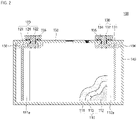
- FIG. 1 is an exploded perspective view of a battery pack according to an embodiment.
- FIG. 2 is a cross-sectional view of a battery cell of FIG. 1
- FIG. 3 is an exploded perspective view of a busbar assembly of FIG. 1 .
- a battery pack 10 may include a plurality of battery cells 100 arranged in one direction (e.g. a first direction) and a busbar assembly 200.
- the busbar assembly 200 may be arranged above the plurality of battery cells 100, e.g., the busbar assembly 200 may continuously overlap tops of all the plurality of battery cells 100.
- each of the battery cells 100 may include an electrode assembly 110, a first terminal 120, a second terminal 130, a case 140, and a cap plate 150.
- the electrode assembly 110 may be arranged in the case 140, with the cap plate 150 sealing the case 140, and the first and second terminals 120 and 130 extending from the electrode assembly 110 through the cap plate 150.
- the electrode assembly 110 may be formed by stacking a stack of a first electrode plate 111, a separator 113, and a second electrode plate 112, e.g., formed in a thin plate shape or a film shape. This type of electrode assembly 110 may be referred to as a stack type.
- the first electrode plate 111 may serve as a negative electrode
- the second electrode plate 112 may serve as a positive electrode, or vice versa.
- the first electrode plate 111 may be formed by coating a first electrode active material, e.g., graphite or carbon, on a first electrode current collector made of a metal foil, e.g., copper, copper alloy, nickel or nickel alloy.
- the first electrode plate 111 may include a first electrode uncoated region 111a which is an area to which the first electrode active material is not applied.
- the second electrode plate 112 may be formed by coating a second electrode active material, e.g., a transition metal oxide, on a second electrode current collector made of a metal foil, e.g., aluminum or an aluminum alloy.
- the second electrode plate 112 may include a second electrode uncoated region 112a that is an area to which the second electrode active material is not applied.
- the first electrode uncoated region 111a may protrude to one side of the electrode assembly 110, and the second electrode uncoated region 112a may protrude to the other (e.g. opposite) side of the electrode assembly 110.
- the separator 113 may be positioned between the first electrode plate 111 and the second electrode plate 112 to prevent a short circuit and to enable the movement of lithium ions, and may include, e.g., polyethylene, polypropylene, or a composite film of polyethylene and polypropylene.
- the first terminal 120 may be formed of a metal and may be electrically connected to the first electrode plate 111.
- the first terminal 120 may include a first current collecting plate 121, a first terminal pillar 122, and a first terminal plate 124.
- the first current collecting plate 121 may be electrically connected to the first electrode uncoated region 111a protruding to one end of the electrode assembly 110.
- a terminal hole may be formed in an upper portion of the first current collecting plate 121, and the first terminal pillar 122 may be inserted into the terminal hole to be riveted and/or welded.
- the first terminal pillar 122 may protrude and extend upward a predetermined length through the cap plate 150, and may be electrically connected to the first current collector plate 121 under the cap plate 150.
- the first terminal plate 124 may be coupled to the first terminal pillar 122.
- the second terminal 130 may be made of a metal and may be electrically connected to the second electrode plate 112.
- the second terminal 130 may include a second current collecting plate 131, a second terminal pillar 132, and a second terminal plate 134.
- the second current collecting plate 131 may be electrically connected to the second electrode uncoated region 112a protruding from one end of the electrode assembly 110.
- a terminal hole may be formed in an upper portion of the second current collecting plate 131, and the second terminal pillar 132 may be inserted into the terminal hole to be riveted and/or welded.
- the second terminal pillar 132 may protrude and extend upward a predetermined length through the cap plate 150, and may be electrically connected to the second current collecting plate 131 at the lower portion of the cap plate 150.
- the second terminal plate 134 may be coupled to the second terminal pillar 132.
- the second terminal plate 134 may be electrically connected to the cap plate 150, and the cap plate 150 and the case 140 may have the same polarity (e.g., positive polarity) as the second terminal 130.
- the case 140 may be made of, e.g., aluminum, an aluminum alloy, or a conductive metal such as nickel-plated steel, and may have a substantially hexahedral shape in which an opening, into which the electrode assembly 110 can be inserted and seated, is formed.
- the cap plate 150 may be coupled to the opening of the case 140 to seal the case 140.
- the cap plate 150 may seal the opening of the case 140, and may be made of the same material as the case 140. In some examples, the cap plate 150 may be coupled to the case 140 by laser welding.
- An upper coupling member 155 may be formed between the cap plate 150 and each of the first terminal pillar 122 and the second terminal pillar 132 on the cap plate 150. In addition, the upper coupling member 155 may be in close contact with the cap plate 150. The upper coupling member 155 may insulate the first terminal pillar 122 and the second terminal pillar 132 from the cap plate 150.
- the upper coupling member 155 formed on the second terminal pillar 132 may electrically connect the second terminal plate 134 and the cap plate 150 to each other, and accordingly, the second terminal 130 may have the same polarity as the cap plate 150 and the case 140.
- a lower insulating member 156 may be formed between each of the first current collecting plate 121 and the second current collecting plate 131 and the cap plate 150, and short circuits between the first current collecting plate 121 and the cap plate 150 and between the second current collecting plate 131 and the cap plate 150 may be prevented.
- the busbar assembly 200 may include a busbar 210, a flexible substrate 220, a first insulation film 230, and a second insulation film 240.
- the busbar assembly 200 may be seated on top of the plurality of battery cells 100.
- the busbar 210 may electrically connect the plurality of battery cells 100
- the busbar 210 may connect the plurality of battery cells 100 in series and/or in parallel.
- the busbar 210 may include a plurality of busbars 210 to electrically connect the plurality of battery cells 100 to each other.
- the busbar 210 may be electrically connected to the first terminal 120 and/or the second terminal 130 of the battery cell 100.
- the busbar 210 may electrically connect the battery cells 100 that are not adjacent to each other.
- the busbar 210 may electrically connect the first terminal 120 of one of the battery cells 100 and the first terminal 120 or the second terminal 130 of another one of the battery cells 100.
- the busbar 210 may be welded to the first terminal 120 or the second terminal 130 of each of the battery cells 100.
- the plurality of busbars 210 may be coated or laminated with the first insulation film 230 and the second insulation film 240. In some examples, the plurality of busbars 210 may be located on the same plane between the first insulation film 230 and the second insulation film 240, e.g., tops of the busbars 210 may be coplanar with each other and bottoms of the busbars 210 may be coplanar with each other. In some examples, an output terminal 215 for drawing out the output voltage of the battery pack 10 may be formed on the busbar 210. The output terminal 215 may be drawn out from the battery pack 10 in the same direction.
- each of the busbars 210 may include a body 212 and a connection part 211 that extends (or protrudes) to one side of the body 212 and is electrically connected to the first terminal 120 and/or the second terminal 130 of the battery cell 100.
- the connection part 211 may include, e.g., consist of, two connection parts.
- the connection part 211 may be welded to the first terminal 120 or the second terminal 130 of the battery cell 100.
- the connection part 211 may be welded to the first terminal plate 124 or the second terminal plate 134.
- top surfaces of the body 212 and the connection part 211 may be coplanar with each other, and bottom surfaces of the body 212 and the connection part 211 may be coplanar with each other to define a, e.g., completely, flat busbar 210.
- each body 212 may extend along the X-axis, and two connection parts 211 may extend, e.g., in parallel to each other, from opposite ends of the body 212 in the Y-axis.
- two rows of bodies 212 along the X-axis may be arranged to overlap the first terminals 120 of the battery cells 100, and two rows of bodies 212 along the X-axis may be arranged to overlap the second terminals 130 of the battery cells 100.
- the busbars 210 may be arranged in a zigzag pattern, e.g., connection parts 211 of one of the two rows may face connection parts 211 of the other of the two rows.
- the flexible substrate 220 may be positioned on top of the plurality of battery cells 100.
- the flexible substrate 220 may extend in a direction in which the plurality of battery cells 100 are arranged, e.g., along the X-axis, and may be formed to pass through the center of the cap plate 150.
- the flexible substrate 220 may extend between the pairs of rows of the busbars 210, e.g., a width of the flexible substrate 220 in the Y-axis may fit between the pairs of rows of the busbars 210.
- the flexible substrate 220 may be referred to as a flexible printed circuit assembly (FPCA) or a flexible printed circuit board (FPCB).
- the flexible substrate 220 may measure status information (e.g. state information) of the battery cells 100, e.g., voltage and/or temperature, of the battery cell 100.
- the flexible substrate 220 may include a temperature measuring unit 221, i.e., a temperature measurer, for measuring the temperature of the battery cell 100 and a sensing plate 225 for measuring the voltage of the battery cell 100.
- the flexible substrate 220 may include a plurality of temperature measuring units 221 and a plurality of sensing plates 225 to measure the temperatures and voltages of various parts of the plurality of battery cells 100.
- the temperature measuring unit 221 may directly contact the battery cell 100 to measure the temperature of the battery cell 100.
- the temperature measuring unit 221 may include a temperature sensor, e.g., a thermistor, and a connection plate welded to the battery cell 100.
- the temperature measuring unit 221 may sense the temperature of the battery cell 100 by measuring a resistance value of the temperature sensor, i.e., the thermistor.
- a connector 227 may be coupled to one end of the flexible substrate 220, and the flexible substrate 220 may be connected to an external system through the connector 227.
- the first insulation film 230 and the second insulation film 240 may complete the busbar assembly 200 by laminating, e.g., surrounding or encapsulating, the busbar 210 and the flexible substrate 220.
- the first insulation film 230 may be coupled from the top of the busbar 210 and the flexible substrate 220
- the second insulation film 240 may be coupled from the bottom of the busbar 210 and the flexible substrate 220.
- the first insulation film 230 may extend continuously above the busbar 210 and the flexible substrate 220
- the second insulation film 240 may extend continuously below the busbar 210 and the flexible substrate 220.
- the first insulation film 230 and the second insulation film 240 are thermally fused to form the busbar assembly 200, e.g., so the busbar 210 and the flexible substrate 220 may be embedded within the fused, e.g., laminated, structure of the first and second insulation films 230 and 240.
- the first insulation film 230 and/or the second insulation film 240 may include, e.g., a polyethylene terephthalate (PET) film, a polyimide (PI) film, a polyethylene naphthalate (PEN) film, or a polycarbonate (PC) film.
- PET polyethylene terephthalate
- PI polyimide
- PEN polyethylene naphthalate
- PC polycarbonate
- the first insulation film 230 and/or the second insulation film 240 may be any film or sheet including an insulating material.
- the first insulation film 230 and/or the second insulation film 240 may be an insulating film.
- the first insulation film 230 and the second insulation film 240 may include terminal holes 231 and 241 formed at positions corresponding to the first terminal plate 124 and the second terminal plate 134 of the battery cell 100, respectively.
- edges of the first insulation film 230 and the second insulation film 240 along the X-axis may be completely fused with each to surround the busbars 210, such that only the terminal holes 231 and 241 may expose portions of the busbars 210.
- the terminal holes 231 and 241 may expose the connection part 211 of the busbar 210 electrically connected to the first terminal plate 124 or the second terminal plate 134.
- the first insulation film 230 may include a first hole 232 exposing the temperature measuring unit 221 and a second hole 233 exposing a portion of the sensing plate 225 for measuring a voltage.
- the first insulation film 230 may cover the remaining portion except for the portion exposed by the second hole 233 in the sensing plate 225, thereby preventing the sensing plate 225 from being corroded and preventing a short circuit from occurring between the sensing plate 225 and an external circuit. That is, the first insulation film 230 may have the same effect as coating the surface of the sensing plate 225.
- the first insulation film 230 may prevent unnecessary short circuit between the busbar 210 and an external component.
- the second insulation film 240 may include a first hole 242 exposing the temperature measuring unit 221.
- the first hole 232 of the first insulation film 230 and the first hole 242 of the second insulation film 240 are formed at the same location, e.g., the first and second holes 232 and 242 may vertically overlap each other.
- the second insulation film 240 is located under the busbar 210 and the flexible substrate 220, and thus a second hole exposing the sensing plate 225 is not necessarily formed.
- the second insulation film 240 may insulate the busbar 210 and the cap plate 150 from each other.
- the busbar assembly 200 may be completed by positioning the busbar 210 and the flexible substrate 220 between the first insulation film 230 and the second insulation film 240 and thermally fusing the first insulation film 230 and the second insulation film 240. Therefore, in the battery pack 10 according to embodiments, a separate holder or support member for fixing the busbar 210 and the flexible substrate 220 is not required, thereby reducing costs.
- the volume, i.e., the height (e.g., along the Z-axis), of the battery pack 10 can be reduced, thereby increasing the energy density (or capacity per unit volume).
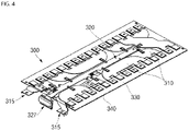
- FIG. 4 is a perspective view of a busbar assembly according to another embodiment of the present disclosure.
- FIG. 5 is an exploded perspective view of the busbar assembly of FIG. 4 .
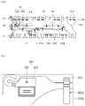
- FIG. 6 is a plan view of a state in which the busbar of FIG. 5 and a flexible substrate are combined.
- FIG. 7 is an enlarged view of portion A of FIG. 6 .
- FIG. 8 is a cross-sectional view taken along line B-B of FIG. 6 .
- a busbar assembly 300 may include busbars 310A and 310B (e.g. first and second sub-busbars), a flexible substrate 320, a first insulation film 330, a second insulation film 340, and a third insulation film 350.
- the busbar assembly 300 may further include the third insulation film 350.
- the third insulation film 350 may be positioned between the first insulation film 330 and the second insulation film 340.
- the films may be insulating films.
- the busbars 310A and 310B may electrically connect the plurality of battery cells 100 to each other.
- the busbars 310A and 310B may include a first busbar 310A positioned between the first insulation film 330 and the third insulation film 350, and a second busbar 310B positioned between the second insulation film 340 and the third insulation film 350.
- the busbars 310A and 310B may include the first busbar 310A positioned above the third insulation film 350 and the second busbar 310B positioned below the third insulation film 350.
- the first busbar 310A may be located on the same plane between the first insulation film 330 and the third insulation film 350.
- the first busbar 310A may include a body 312a and a connection part 311a extending to one side of the body 312a and electrically connected to the first terminal 120 and/or the second terminal 130 of the battery cell 100.
- the connection part 311a may be connected to at least two or more first terminals 120 and/or second terminals 130.
- FIG. 5 illustrates that the first busbar 310A includes four connection parts 311a, the first busbar 310A may include four or more connection parts 311a.
- the body 312a of the first busbar 310A may be stacked to e.g., vertically, overlap a body 312b of the second busbar 310B, but the third insulation film 350 may be positioned between the body 312a of the first busbar 310A and the body 312b of the second busbar 310B to prevent a short circuit therebetween.
- the second busbar 310B may be positioned between the third insulation film 350 and the second insulation film 340.
- the second busbar 310B may include the body 312b, a connection part 311b extending to one side of the body 312b to be electrically connected to the first terminal 120 and/or the second terminal 130 of the battery cell 100, and a bent portion 313b located between the body 312b and the connection part 311b.
- the second busbar 310B may further include the bent portion 313b as compared with the first busbar 310A, e.g., the bent portion 313b may extend in the Z-axis to connect the connection part 311b to the body 312b.
- the body 312b may be positioned between the third insulation film 350 and the second insulation film 340, and the connection part 311b may be positioned at a relatively higher position than the body 312b, e.g., along the Z-axis in FIG. 5 .
- the second busbar 310B includes the bent portion 313b located between the body 312b and the connection part 311b, and thus the connection part 311b and the body 312b are not formed on the same plane, e.g., the connection part 311b and the body 312b with the bent portion 313b therebetween may have a step shape.
- connection part 311a of the first busbar 310A and the connection part 311b of the second busbar 310B may be formed on the same plane, e.g., while the body 312a of the first busbar 310A and the body 312b of the second busbar 310B may be formed on different planes. Accordingly, the busbar assembly 300 may be stably seated on the first terminal 120 and the second terminal 130 of the battery cell 100.
- the height of the bent portion 313b may correspond, e.g., equal, to the thickness of the third insulation film 350.
- an output terminal 315 for drawing out an output voltage of the battery pack 10 may be formed on the second busbar 310B.
- the output terminal 315 may be drawn out from the battery pack 10 in the same direction.
- the flexible substrate 320 may be positioned between the first insulation film 330 and the third insulation film 350.
- the flexible substrate 320 may be formed similarly to the flexible substrate 220 of FIG. 3 .
- the flexible substrate 320 may be configured to measure a state information of the battery cells 100.
- the flexible substrate 320 may include a temperature measuring unit 321 (e.g. a temperature measurer) for measuring the temperature of the battery cell 100 and a sensing plate 325 for measuring the voltage of the battery cell 100.
- the temperature measuring unit 321 may include a temperature sensor 322, e.g., a thermistor, and a connection plate 323 welded to the battery cell 100.
- the temperature sensor 322 may be attached to the flexible substrate 320 through soldering, and the connection plate 323 may be welded to the cap plate 150 of the battery cell 100 with a laser.
- a connector 327 may be coupled to one end of the flexible substrate 320, and the flexible substrate 320 may be connected to an external system through the connector 327.
- the sensing plate 325 may include a first sensing plate 325a electrically connected to the first busbar 310A and a second sensing plate 325b electrically connected to the second busbar 310B.
- One end of the first sensing plate 325a may be electrically connected to the flexible substrate 320 and the other end thereof may be electrically connected to the body 312a of the first busbar 310A.
- the flexible substrate 320 and the first busbar 310A are positioned on the third insulation film 350, and the first sensing plate 325a may include a bent portion (C1) according e.g., substantially equal, to the thickness difference between the flexible substrate 320 and the first busbar 310A.
- One end of the second sensing plate 325b may be electrically connected to the flexible substrate 320 and the other end thereof may be electrically connected to the body 312b of the second busbar 310B.
- the other end of the second sensing plate 325b may pass through the third insulation film 350 and may be electrically connected to the body 312b of the second busbar 310B. Since the flexible substrate 320 is located on the upper portion of the third insulation film 350 and the body 312a of the second busbar 310B is located on the lower portion of the third insulation film 350, the second sensing plate 325b may include a bent portion C2 according, e.g., substantially equal, to the height difference between the flexible substrate 320 and the second busbar 310B.
- the height of the bent portion C2 of the second sensing plate 325b may be larger than the height of the bent portion C1 of the first sensing plate 325a, e.g., along the Z-axis in FIG. 5 .
- the first insulation film 330 may cover the first busbar 310A and the flexible substrate 320 located on the third insulation film 350.
- the second insulation film 340 may cover the second busbar 310B located under the third insulation film 350.
- the first insulation film 330 and the second insulation film 340 may complete the busbar assembly 300 by laminating the busbars 310A and 310B and the flexible substrate 320 located on the upper and lower portions of the third insulation film 350.
- the first insulation film 330 and the second insulation film 340 may be thermally fused, e.g., as discussed previously with reference to the busbar assembly 200 in FIG. 3 , thereby forming the busbar assembly 300.
- the first insulation film 330 and the second insulation film 340 may be formed to have the same size (e.g., area), and the third insulation film 350 may be formed to have a smaller size (e.g., area) than, e.g., each of, the first and second insulation films 330 and 340, e.g., the third insulation film 350 may have a shorter length and a shorter width in the respective X-axis and Y-axis than each of the first and second insulation films 330 and 340.
- the first insulation film 330 and the second insulation film 340 may include terminal holes 331 and 341 formed at positions corresponding to, e.g., overlapping, the first terminal plate 124 and the second terminal plate 134 of the battery cell 100, respectively.
- the first insulation film 330 may include a first hole 332 exposing the temperature measuring unit 321 and a second hole 333 exposing a portion of the sensing plate 325 for measuring a voltage.
- the second insulation film 340 may include a first hole 342 exposing the temperature measuring unit 321.
- the third insulation film 350 may be positioned between the first insulation film 330 and the second insulation film 340, and may insulate the first busbar 310A and the second busbar 310B from each other.
- the third insulation film 350 may be referred to as a flame retardant barrier (FRB), a flame retardant film, or a flame retardant sheet.
- the third insulation film 350 may include a flame retardant material.
- the third insulation film 350 may be formed to have a smaller size (e.g., area) than the first and second insulation films 330 and 340, and may cover the bodies 312a and 312b of the busbars 310A and 310B and may expose connection parts 311a and 311b.
- the third insulation film 350 may include a through-hole 353 exposing a portion of the second sensing plate 325b. The through-hole 353 may be formed at a position corresponding to the second hole 333 of the first insulation film 330.
- embodiments provide a battery pack with improved busbar coupling structure, thereby improving energy density, for example, by lowering a height of the battery pack. That is, as described above, the battery pack according to embodiments includes a busbar assembly having a busbar and a flexible substrate that are laminated with an insulation film, thereby lowering a height of the battery pack to improve energy density.
- the laminated structure of the busbar assembly eliminates the need of a separate busbar holder or support member, thereby reducing costs, for example.
Landscapes
- Chemical & Material Sciences (AREA)
- Chemical Kinetics & Catalysis (AREA)
- Electrochemistry (AREA)
- General Chemical & Material Sciences (AREA)
- Engineering & Computer Science (AREA)
- Manufacturing & Machinery (AREA)
- Microelectronics & Electronic Packaging (AREA)
- Connection Of Batteries Or Terminals (AREA)
- Battery Mounting, Suspending (AREA)
Abstract
A battery pack includes battery cells arranged in a first direction, and a busbar assembly coupled to upper portions of the battery cells, the busbar assembly having a busbar electrically connected to the battery cells, a flexible substrate configured to measure a state information of the battery cells, and an insulating film surrounding the busbar and the flexible substrate.
Description
- Embodiments of the present disclosure relate to a battery pack.
- In general, unlike primary batteries which are not rechargeable, a secondary battery can be discharged and charged. The secondary battery is used as an energy source of, e.g., a mobile device, an electric vehicle, a hybrid vehicle, an electric bicycle or an uninterruptible power supply (UPS). According to the type of external device used with the batteries, a single secondary battery may be used or a battery module or pack, in which a plurality of batteries are bundled up by electrically connecting the batteries, may be used.
- Small mobile devices, e.g., cell phones, can be operated for a certain period of time with the output and capacity of a single battery. However, when long-time operation and high-power operation are required, e.g., in electric vehicles or hybrid vehicles that consume a lot of power, a battery module or pack including a large number of batteries is preferred, so the output voltage or output current can be increased according to the number of built-in batteries.
- The battery pack according to embodiments may include battery cells arranged in a first direction, and a busbar assembly coupled to upper portions of the battery cells, the busbar assembly having a busbar electrically connected to the battery cells, a flexible substrate configured to measure a state information of the battery cells, and an insulating film surrounding the busbar and the flexible substrate.
- The insulating film may include a first insulation film located on the upper portion of the busbar and the flexible substrate, and a second insulation film located on the lower portion of the busbar and the flexible substrate.
- The busbar may include a body and a connection part extending to one side of the body and coupled to the electrode terminal of the battery cell, and each of the first insulation film and the second insulation film includes a terminal hole exposing the connection part.
- The flexible substrate may include a temperature measuring unit for measuring the temperature of the battery cell, and a sensing plate for measuring the voltage of the battery cell, and each of the first insulation film and the second insulation film may include a first hole exposing the temperature measurement unit.
- The first insulation film may include a second hole exposing a portion of the sensing plate.
- The battery pack may further include a third insulation film positioned between the first insulation film and the second insulation film.
- The busbar may include a first busbar located between the first insulation film and the third insulation film, and a second busbar located between the third insulation film and the second insulation film.
- The busbar may include a body and a connection part extending to one side of the body and coupled to the electrode terminal of each of the battery cells, and the second busbar may further include a bent portion located between the body and the connection part.
- The height of the bent portion may correspond to the thickness of the third insulation film.
- The third insulation film may be formed to have a smaller area than the first insulation film and the second insulation film, and may be located between the body of the first busbar and the body of the second busbar.
- The flexible substrate may include a sensing plate for measuring the voltage of the battery cells, and the sensing plate may include a first sensing plate electrically connected to the first busbar and a second sensing plate electrically connected to the second busbar.
- The third insulation film may include a through-hole exposing a portion of the second sensing plate.
- The second sensing plate may be electrically connected to the body of the second busbar through the through-hole.
- The bent portion of the second sensing plate may be formed to have a larger height than the bent portion of the first sensing plate.
- At least some of the above and other features of the invention are set out in the claims.
- Features will become apparent to those of skill in the art by describing in detail embodiments with reference to the attached drawings, in which:
-
FIG. 1 is an exploded perspective view of a battery pack according to an embodiment of the present disclosure. -
FIG. 2 is a cross-sectional view of a battery cell in the battery pack ofFIG. 1 . -
FIG. 3 is an exploded perspective view of a busbar assembly in the battery pack ofFIG. 1 . -
FIG. 4 is a perspective view of a busbar assembly in a battery pack according to another embodiment. -
FIG. 5 is an exploded perspective view of the busbar assembly ofFIG. 4 . -
FIG. 6 is a plan view of a state in which the busbar ofFIG. 5 and a flexible substrate are combined. -
FIG. 7 is an enlarged view of portion A ofFIG. 6 . -
FIG. 8 is a cross-sectional view taken along line B-B ofFIG. 6 . - Example embodiments will now be described more fully hereinafter with reference to the accompanying drawings; however, they may be embodied in different forms and should not be construed as limited to the embodiments set forth herein. Rather, these embodiments are provided so that this disclosure will be thorough and complete, and will fully convey example implementations to those skilled in the art.
- In the drawing figures, the dimensions of layers and regions may be exaggerated for clarity of illustration. It will also be understood that when a layer or element is referred to as being "on" another layer or substrate, it can be directly on the other layer or substrate, or intervening layers may also be present. Like reference numerals refer to like elements throughout.
- As used herein, the term "and/or" includes any and all combinations of one or more of the associated listed items. In addition, it will be understood that when an element A is referred to as being "connected to" an element B, the element A can be directly connected to the element B or an intervening element C may be present therebetween such that the element A and the element B are indirectly connected to each other.
- As used herein, the singular forms are intended to include the plural forms as well, unless the context clearly indicates otherwise. It will be further understood that the terms "comprise or include" and/or "comprising or including," when used in this specification, specify the presence of stated features, numbers, steps, operations, elements, and/or components, but do not preclude the presence or addition of one or more other features, numbers, steps, operations, elements, components, and/or groups thereof.
- Spatially relative terms, e.g., "beneath," "below," "lower," "above," "upper," and the like, may be used herein for ease of description to describe one element or feature's relationship to another element(s) or feature(s) as illustrated in the figures. It will be understood that the spatially relative terms are intended to encompass different orientations of the device in use or operation in addition to the orientation depicted in the figures. For example, if the element or feature in the figures is turned over, elements described as "below" or "beneath" other elements or features would then be oriented "on" or "above" the other elements or features. Thus, the term "below" can encompass both an orientation of above and below, for example.
-
FIG. 1 is an exploded perspective view of a battery pack according to an embodiment.FIG. 2 is a cross-sectional view of a battery cell ofFIG. 1 , andFIG. 3 is an exploded perspective view of a busbar assembly ofFIG. 1 . - Referring to
FIG. 1 , abattery pack 10 according to an embodiment of the present disclosure may include a plurality ofbattery cells 100 arranged in one direction (e.g. a first direction) and abusbar assembly 200. Thebusbar assembly 200 may be arranged above the plurality ofbattery cells 100, e.g., thebusbar assembly 200 may continuously overlap tops of all the plurality ofbattery cells 100. - Referring to
FIG. 2 , each of thebattery cells 100 may include anelectrode assembly 110, afirst terminal 120, asecond terminal 130, acase 140, and acap plate 150. Theelectrode assembly 110 may be arranged in thecase 140, with thecap plate 150 sealing thecase 140, and the first andsecond terminals electrode assembly 110 through thecap plate 150. - The
electrode assembly 110 may be formed by stacking a stack of afirst electrode plate 111, aseparator 113, and asecond electrode plate 112, e.g., formed in a thin plate shape or a film shape. This type ofelectrode assembly 110 may be referred to as a stack type. In some examples, thefirst electrode plate 111 may serve as a negative electrode, and thesecond electrode plate 112 may serve as a positive electrode, or vice versa. - In some examples, the
first electrode plate 111 may be formed by coating a first electrode active material, e.g., graphite or carbon, on a first electrode current collector made of a metal foil, e.g., copper, copper alloy, nickel or nickel alloy. Thefirst electrode plate 111 may include a first electrodeuncoated region 111a which is an area to which the first electrode active material is not applied. In some examples, thesecond electrode plate 112 may be formed by coating a second electrode active material, e.g., a transition metal oxide, on a second electrode current collector made of a metal foil, e.g., aluminum or an aluminum alloy. Thesecond electrode plate 112 may include a second electrodeuncoated region 112a that is an area to which the second electrode active material is not applied. The first electrodeuncoated region 111a may protrude to one side of theelectrode assembly 110, and the second electrodeuncoated region 112a may protrude to the other (e.g. opposite) side of theelectrode assembly 110. Theseparator 113 may be positioned between thefirst electrode plate 111 and thesecond electrode plate 112 to prevent a short circuit and to enable the movement of lithium ions, and may include, e.g., polyethylene, polypropylene, or a composite film of polyethylene and polypropylene. - The
first terminal 120 may be formed of a metal and may be electrically connected to thefirst electrode plate 111. In some examples, thefirst terminal 120 may include a firstcurrent collecting plate 121, a firstterminal pillar 122, and a firstterminal plate 124. The firstcurrent collecting plate 121 may be electrically connected to the first electrodeuncoated region 111a protruding to one end of theelectrode assembly 110. A terminal hole may be formed in an upper portion of the firstcurrent collecting plate 121, and the firstterminal pillar 122 may be inserted into the terminal hole to be riveted and/or welded. The firstterminal pillar 122 may protrude and extend upward a predetermined length through thecap plate 150, and may be electrically connected to the firstcurrent collector plate 121 under thecap plate 150. The firstterminal plate 124 may be coupled to the firstterminal pillar 122. - The
second terminal 130 may be made of a metal and may be electrically connected to thesecond electrode plate 112. In some examples, thesecond terminal 130 may include a second current collectingplate 131, a secondterminal pillar 132, and a secondterminal plate 134. The second current collectingplate 131 may be electrically connected to the second electrodeuncoated region 112a protruding from one end of theelectrode assembly 110. A terminal hole may be formed in an upper portion of the second current collectingplate 131, and the secondterminal pillar 132 may be inserted into the terminal hole to be riveted and/or welded. The secondterminal pillar 132 may protrude and extend upward a predetermined length through thecap plate 150, and may be electrically connected to the second current collectingplate 131 at the lower portion of thecap plate 150. The secondterminal plate 134 may be coupled to the secondterminal pillar 132. The secondterminal plate 134 may be electrically connected to thecap plate 150, and thecap plate 150 and thecase 140 may have the same polarity (e.g., positive polarity) as thesecond terminal 130. - The
case 140 may be made of, e.g., aluminum, an aluminum alloy, or a conductive metal such as nickel-plated steel, and may have a substantially hexahedral shape in which an opening, into which theelectrode assembly 110 can be inserted and seated, is formed. Thecap plate 150 may be coupled to the opening of thecase 140 to seal thecase 140. - The
cap plate 150 may seal the opening of thecase 140, and may be made of the same material as thecase 140. In some examples, thecap plate 150 may be coupled to thecase 140 by laser welding. Anupper coupling member 155 may be formed between thecap plate 150 and each of the firstterminal pillar 122 and the secondterminal pillar 132 on thecap plate 150. In addition, theupper coupling member 155 may be in close contact with thecap plate 150. Theupper coupling member 155 may insulate the firstterminal pillar 122 and the secondterminal pillar 132 from thecap plate 150. In some examples, theupper coupling member 155 formed on the secondterminal pillar 132 may electrically connect the secondterminal plate 134 and thecap plate 150 to each other, and accordingly, thesecond terminal 130 may have the same polarity as thecap plate 150 and thecase 140. A lower insulatingmember 156 may be formed between each of the firstcurrent collecting plate 121 and the second current collectingplate 131 and thecap plate 150, and short circuits between the firstcurrent collecting plate 121 and thecap plate 150 and between the second current collectingplate 131 and thecap plate 150 may be prevented. - Referring back to
FIG. 1 , thebusbar assembly 200 may include abusbar 210, aflexible substrate 220, afirst insulation film 230, and asecond insulation film 240. Thebusbar assembly 200 may be seated on top of the plurality ofbattery cells 100. Thebusbar 210 may electrically connect the plurality ofbattery cells 100 - Referring to
FIG. 3 , thebusbar 210 may connect the plurality ofbattery cells 100 in series and/or in parallel. Thebusbar 210 may include a plurality ofbusbars 210 to electrically connect the plurality ofbattery cells 100 to each other. Thebusbar 210 may be electrically connected to thefirst terminal 120 and/or thesecond terminal 130 of thebattery cell 100. In some examples, thebusbar 210 may electrically connect thebattery cells 100 that are not adjacent to each other. In some examples, thebusbar 210 may electrically connect thefirst terminal 120 of one of thebattery cells 100 and thefirst terminal 120 or thesecond terminal 130 of another one of thebattery cells 100. Thebusbar 210 may be welded to thefirst terminal 120 or thesecond terminal 130 of each of thebattery cells 100. The plurality ofbusbars 210 may be coated or laminated with thefirst insulation film 230 and thesecond insulation film 240. In some examples, the plurality ofbusbars 210 may be located on the same plane between thefirst insulation film 230 and thesecond insulation film 240, e.g., tops of thebusbars 210 may be coplanar with each other and bottoms of thebusbars 210 may be coplanar with each other. In some examples, anoutput terminal 215 for drawing out the output voltage of thebattery pack 10 may be formed on thebusbar 210. Theoutput terminal 215 may be drawn out from thebattery pack 10 in the same direction. - For example, as illustrated in
FIG. 3 , each of thebusbars 210 may include abody 212 and aconnection part 211 that extends (or protrudes) to one side of thebody 212 and is electrically connected to thefirst terminal 120 and/or thesecond terminal 130 of thebattery cell 100. In some examples, theconnection part 211 may include, e.g., consist of, two connection parts. Theconnection part 211 may be welded to thefirst terminal 120 or thesecond terminal 130 of thebattery cell 100. In some examples, theconnection part 211 may be welded to the firstterminal plate 124 or the secondterminal plate 134. For example, as illustrated inFIG. 3 , top surfaces of thebody 212 and theconnection part 211 may be coplanar with each other, and bottom surfaces of thebody 212 and theconnection part 211 may be coplanar with each other to define a, e.g., completely,flat busbar 210. - For example, as further illustrated in
FIG. 3 , eachbody 212 may extend along the X-axis, and twoconnection parts 211 may extend, e.g., in parallel to each other, from opposite ends of thebody 212 in the Y-axis. For example, referring toFIGS. 1 and3 , two rows ofbodies 212 along the X-axis may be arranged to overlap thefirst terminals 120 of thebattery cells 100, and two rows ofbodies 212 along the X-axis may be arranged to overlap thesecond terminals 130 of thebattery cells 100. For example, in each of the two rows ofbodies 212, thebusbars 210 may be arranged in a zigzag pattern, e.g.,connection parts 211 of one of the two rows may faceconnection parts 211 of the other of the two rows. - The
flexible substrate 220 may be positioned on top of the plurality ofbattery cells 100. In some examples, theflexible substrate 220 may extend in a direction in which the plurality ofbattery cells 100 are arranged, e.g., along the X-axis, and may be formed to pass through the center of thecap plate 150. For example, as illustrated inFIG. 3 , theflexible substrate 220 may extend between the pairs of rows of thebusbars 210, e.g., a width of theflexible substrate 220 in the Y-axis may fit between the pairs of rows of thebusbars 210. In some examples, theflexible substrate 220 may be referred to as a flexible printed circuit assembly (FPCA) or a flexible printed circuit board (FPCB). In some examples, theflexible substrate 220 may measure status information (e.g. state information) of thebattery cells 100, e.g., voltage and/or temperature, of thebattery cell 100. - The
flexible substrate 220 may include atemperature measuring unit 221, i.e., a temperature measurer, for measuring the temperature of thebattery cell 100 and asensing plate 225 for measuring the voltage of thebattery cell 100. In some examples, theflexible substrate 220 may include a plurality oftemperature measuring units 221 and a plurality ofsensing plates 225 to measure the temperatures and voltages of various parts of the plurality ofbattery cells 100. Thetemperature measuring unit 221 may directly contact thebattery cell 100 to measure the temperature of thebattery cell 100. In some examples, thetemperature measuring unit 221 may include a temperature sensor, e.g., a thermistor, and a connection plate welded to thebattery cell 100. For example, thetemperature measuring unit 221 may sense the temperature of thebattery cell 100 by measuring a resistance value of the temperature sensor, i.e., the thermistor. In addition, aconnector 227 may be coupled to one end of theflexible substrate 220, and theflexible substrate 220 may be connected to an external system through theconnector 227. - The
first insulation film 230 and thesecond insulation film 240 may complete thebusbar assembly 200 by laminating, e.g., surrounding or encapsulating, thebusbar 210 and theflexible substrate 220. Thefirst insulation film 230 may be coupled from the top of thebusbar 210 and theflexible substrate 220, and thesecond insulation film 240 may be coupled from the bottom of thebusbar 210 and theflexible substrate 220. For example, as illustrated inFIG. 3 , thefirst insulation film 230 may extend continuously above thebusbar 210 and theflexible substrate 220, and thesecond insulation film 240 may extend continuously below thebusbar 210 and theflexible substrate 220. In some examples, after thebusbar 210 and theflexible substrate 220 are positioned between thefirst insulation film 230 and thesecond insulation film 240, thefirst insulation film 230 and thesecond insulation film 240 are thermally fused to form thebusbar assembly 200, e.g., so thebusbar 210 and theflexible substrate 220 may be embedded within the fused, e.g., laminated, structure of the first andsecond insulation films - In some examples, the
first insulation film 230 and/or thesecond insulation film 240 may include, e.g., a polyethylene terephthalate (PET) film, a polyimide (PI) film, a polyethylene naphthalate (PEN) film, or a polycarbonate (PC) film. Thefirst insulation film 230 and/or thesecond insulation film 240 may be any film or sheet including an insulating material. Thefirst insulation film 230 and/or thesecond insulation film 240 may be an insulating film. - The
first insulation film 230 and thesecond insulation film 240 may includeterminal holes terminal plate 124 and the secondterminal plate 134 of thebattery cell 100, respectively. For example, referring toFIG. 3 , edges of thefirst insulation film 230 and thesecond insulation film 240 along the X-axis may be completely fused with each to surround thebusbars 210, such that only theterminal holes busbars 210. In addition, the terminal holes 231 and 241 may expose theconnection part 211 of thebusbar 210 electrically connected to the firstterminal plate 124 or the secondterminal plate 134. Thefirst insulation film 230 may include afirst hole 232 exposing thetemperature measuring unit 221 and asecond hole 233 exposing a portion of thesensing plate 225 for measuring a voltage. Thefirst insulation film 230 may cover the remaining portion except for the portion exposed by thesecond hole 233 in thesensing plate 225, thereby preventing thesensing plate 225 from being corroded and preventing a short circuit from occurring between thesensing plate 225 and an external circuit. That is, thefirst insulation film 230 may have the same effect as coating the surface of thesensing plate 225. In addition, thefirst insulation film 230 may prevent unnecessary short circuit between thebusbar 210 and an external component. - The
second insulation film 240 may include afirst hole 242 exposing thetemperature measuring unit 221. Thefirst hole 232 of thefirst insulation film 230 and thefirst hole 242 of thesecond insulation film 240 are formed at the same location, e.g., the first andsecond holes second insulation film 240 is located under thebusbar 210 and theflexible substrate 220, and thus a second hole exposing thesensing plate 225 is not necessarily formed. Thesecond insulation film 240 may insulate thebusbar 210 and thecap plate 150 from each other. - As described above, the
busbar assembly 200 may be completed by positioning thebusbar 210 and theflexible substrate 220 between thefirst insulation film 230 and thesecond insulation film 240 and thermally fusing thefirst insulation film 230 and thesecond insulation film 240. Therefore, in thebattery pack 10 according to embodiments, a separate holder or support member for fixing thebusbar 210 and theflexible substrate 220 is not required, thereby reducing costs. In addition, in thebattery pack 10 according to embodiments, by fixing thebusbar 210 and theflexible substrate 220 by using thefirst insulation film 230 and thesecond insulation film 240 that are relatively thinner than a holder or a support member, the volume, i.e., the height (e.g., along the Z-axis), of thebattery pack 10 can be reduced, thereby increasing the energy density (or capacity per unit volume). -
FIG. 4 is a perspective view of a busbar assembly according to another embodiment of the present disclosure.FIG. 5 is an exploded perspective view of the busbar assembly ofFIG. 4 .FIG. 6 is a plan view of a state in which the busbar ofFIG. 5 and a flexible substrate are combined.FIG. 7 is an enlarged view of portion A ofFIG. 6 .FIG. 8 is a cross-sectional view taken along line B-B ofFIG. 6 . - Referring to
FIGS. 4 to 8 , abusbar assembly 300 may includebusbars flexible substrate 320, afirst insulation film 330, asecond insulation film 340, and athird insulation film 350. In some examples, as compared to thebusbar assembly 200 ofFIG. 3 , thebusbar assembly 300 may further include thethird insulation film 350. Thethird insulation film 350 may be positioned between thefirst insulation film 330 and thesecond insulation film 340. The films may be insulating films. - The
busbars battery cells 100 to each other. Thebusbars first busbar 310A positioned between thefirst insulation film 330 and thethird insulation film 350, and asecond busbar 310B positioned between thesecond insulation film 340 and thethird insulation film 350. In other words, thebusbars first busbar 310A positioned above thethird insulation film 350 and thesecond busbar 310B positioned below thethird insulation film 350. - The
first busbar 310A may be located on the same plane between thefirst insulation film 330 and thethird insulation film 350. In some examples, thefirst busbar 310A may include abody 312a and aconnection part 311a extending to one side of thebody 312a and electrically connected to thefirst terminal 120 and/or thesecond terminal 130 of thebattery cell 100. Theconnection part 311a may be connected to at least two or morefirst terminals 120 and/orsecond terminals 130. AlthoughFIG. 5 illustrates that thefirst busbar 310A includes fourconnection parts 311a, thefirst busbar 310A may include four ormore connection parts 311a. In some examples, thebody 312a of thefirst busbar 310A may be stacked to e.g., vertically, overlap abody 312b of thesecond busbar 310B, but thethird insulation film 350 may be positioned between thebody 312a of thefirst busbar 310A and thebody 312b of thesecond busbar 310B to prevent a short circuit therebetween. - The
second busbar 310B may be positioned between thethird insulation film 350 and thesecond insulation film 340. In some examples, thesecond busbar 310B may include thebody 312b, aconnection part 311b extending to one side of thebody 312b to be electrically connected to thefirst terminal 120 and/or thesecond terminal 130 of thebattery cell 100, and abent portion 313b located between thebody 312b and theconnection part 311b. Thesecond busbar 310B may further include thebent portion 313b as compared with thefirst busbar 310A, e.g., thebent portion 313b may extend in the Z-axis to connect theconnection part 311b to thebody 312b. - The
body 312b may be positioned between thethird insulation film 350 and thesecond insulation film 340, and theconnection part 311b may be positioned at a relatively higher position than thebody 312b, e.g., along the Z-axis inFIG. 5 . In other words, thesecond busbar 310B includes thebent portion 313b located between thebody 312b and theconnection part 311b, and thus theconnection part 311b and thebody 312b are not formed on the same plane, e.g., theconnection part 311b and thebody 312b with thebent portion 313b therebetween may have a step shape. Here, theconnection part 311a of thefirst busbar 310A and theconnection part 311b of thesecond busbar 310B may be formed on the same plane, e.g., while thebody 312a of thefirst busbar 310A and thebody 312b of thesecond busbar 310B may be formed on different planes. Accordingly, thebusbar assembly 300 may be stably seated on thefirst terminal 120 and thesecond terminal 130 of thebattery cell 100. In addition, the height of thebent portion 313b may correspond, e.g., equal, to the thickness of thethird insulation film 350. - In some examples, an
output terminal 315 for drawing out an output voltage of thebattery pack 10 may be formed on thesecond busbar 310B. Theoutput terminal 315 may be drawn out from thebattery pack 10 in the same direction. - The
flexible substrate 320 may be positioned between thefirst insulation film 330 and thethird insulation film 350. Theflexible substrate 320 may be formed similarly to theflexible substrate 220 ofFIG. 3 . Theflexible substrate 320 may be configured to measure a state information of thebattery cells 100. Theflexible substrate 320 may include a temperature measuring unit 321 (e.g. a temperature measurer) for measuring the temperature of thebattery cell 100 and asensing plate 325 for measuring the voltage of thebattery cell 100. - For example, as shown in
FIG. 7 , thetemperature measuring unit 321 may include atemperature sensor 322, e.g., a thermistor, and aconnection plate 323 welded to thebattery cell 100. In some examples, thetemperature sensor 322 may be attached to theflexible substrate 320 through soldering, and theconnection plate 323 may be welded to thecap plate 150 of thebattery cell 100 with a laser. In addition, as illustrated inFIG. 5 , aconnector 327 may be coupled to one end of theflexible substrate 320, and theflexible substrate 320 may be connected to an external system through theconnector 327. - As illustrated in
FIGS. 6 and8 , thesensing plate 325 may include afirst sensing plate 325a electrically connected to thefirst busbar 310A and asecond sensing plate 325b electrically connected to thesecond busbar 310B. One end of thefirst sensing plate 325a may be electrically connected to theflexible substrate 320 and the other end thereof may be electrically connected to thebody 312a of thefirst busbar 310A. Theflexible substrate 320 and thefirst busbar 310A are positioned on thethird insulation film 350, and thefirst sensing plate 325a may include a bent portion (C1) according e.g., substantially equal, to the thickness difference between theflexible substrate 320 and thefirst busbar 310A. - One end of the
second sensing plate 325b may be electrically connected to theflexible substrate 320 and the other end thereof may be electrically connected to thebody 312b of thesecond busbar 310B. The other end of thesecond sensing plate 325b may pass through thethird insulation film 350 and may be electrically connected to thebody 312b of thesecond busbar 310B. Since theflexible substrate 320 is located on the upper portion of thethird insulation film 350 and thebody 312a of thesecond busbar 310B is located on the lower portion of thethird insulation film 350, thesecond sensing plate 325b may include a bent portion C2 according, e.g., substantially equal, to the height difference between theflexible substrate 320 and thesecond busbar 310B. In addition, since thethird insulation film 350 is positioned between theflexible substrate 320 and thesecond busbar 310B, the height of the bent portion C2 of thesecond sensing plate 325b may be larger than the height of the bent portion C1 of thefirst sensing plate 325a, e.g., along the Z-axis inFIG. 5 . - The
first insulation film 330 may cover thefirst busbar 310A and theflexible substrate 320 located on thethird insulation film 350. Thesecond insulation film 340 may cover thesecond busbar 310B located under thethird insulation film 350. In some examples, thefirst insulation film 330 and thesecond insulation film 340 may complete thebusbar assembly 300 by laminating thebusbars flexible substrate 320 located on the upper and lower portions of thethird insulation film 350. In some examples, after thebusbars flexible substrate 320, and thethird insulation film 350 are positioned between thefirst insulation film 330 and thesecond insulation film 340, thefirst insulation film 330 and thesecond insulation film 340 may be thermally fused, e.g., as discussed previously with reference to thebusbar assembly 200 inFIG. 3 , thereby forming thebusbar assembly 300. - The
first insulation film 330 and thesecond insulation film 340 may be formed to have the same size (e.g., area), and thethird insulation film 350 may be formed to have a smaller size (e.g., area) than, e.g., each of, the first andsecond insulation films third insulation film 350 may have a shorter length and a shorter width in the respective X-axis and Y-axis than each of the first andsecond insulation films first insulation film 330 and thesecond insulation film 340 may includeterminal holes terminal plate 124 and the secondterminal plate 134 of thebattery cell 100, respectively. Thefirst insulation film 330 may include afirst hole 332 exposing thetemperature measuring unit 321 and asecond hole 333 exposing a portion of thesensing plate 325 for measuring a voltage. Thesecond insulation film 340 may include afirst hole 342 exposing thetemperature measuring unit 321. - The
third insulation film 350 may be positioned between thefirst insulation film 330 and thesecond insulation film 340, and may insulate thefirst busbar 310A and thesecond busbar 310B from each other. In some examples, thethird insulation film 350 may be referred to as a flame retardant barrier (FRB), a flame retardant film, or a flame retardant sheet. For example, thethird insulation film 350 may include a flame retardant material. Thethird insulation film 350 may be formed to have a smaller size (e.g., area) than the first andsecond insulation films bodies busbars connection parts third insulation film 350 may include a through-hole 353 exposing a portion of thesecond sensing plate 325b. The through-hole 353 may be formed at a position corresponding to thesecond hole 333 of thefirst insulation film 330. - By way of summation and review, embodiments provide a battery pack with improved busbar coupling structure, thereby improving energy density, for example, by lowering a height of the battery pack. That is, as described above, the battery pack according to embodiments includes a busbar assembly having a busbar and a flexible substrate that are laminated with an insulation film, thereby lowering a height of the battery pack to improve energy density. In addition, the laminated structure of the busbar assembly eliminates the need of a separate busbar holder or support member, thereby reducing costs, for example.
- Example embodiments have been disclosed herein, and although specific terms are employed, they are used and are to be interpreted in a generic and descriptive sense only and not for purpose of limitation. In some instances, as would be apparent to one of ordinary skill in the art as of the filing of the present application, features, characteristics, and/or elements described in connection with a particular embodiment described herein may be used singly or in combination with features, characteristics, and/or elements described in connection with other embodiments described herein unless otherwise specifically indicated. Accordingly, it will be understood by those of skill in the art that various changes in form and details may be made without departing from the scope of the present invention, which is set forth in the following claims.
Claims (15)
- A battery pack, comprising:battery cells arranged in a first direction; anda busbar assembly coupled to upper portions of the battery cells, the busbar assembly including:a busbar electrically connected to the battery cells,a flexible substrate configured to measure a state information of the battery cells, andan insulating film surrounding the busbar and the flexible substrate.
- The battery pack as claimed in claim 1, wherein the insulating film includes:a first insulation film on an upper portion of the busbar and the flexible substrate, anda second insulation film on a lower portion of the busbar and the flexible substrate.
- The battery pack as claimed in claim 2, wherein:the busbar includes a body and a connection part extending to one side of the body, the connection part being coupled to an electrode terminal of a corresponding one of the battery cells, andeach of the first insulation film and the second insulation film includes a terminal hole exposing the connection part.
- The battery pack as claimed in claim 2 or 3, wherein the flexible substrate includes:a temperature measurer configured to measure a temperature of the battery cells, each of the first insulation film and the second insulation film including a first hole exposing the temperature measurer, anda sensing plate configured to measure a voltage of the battery cells.
- The battery pack as claimed in claim 4, wherein the first insulation film includes a second hole exposing a portion of the sensing plate.
- The battery pack as claimed in claim 2, further comprising a third insulation film between the first insulation film and the second insulation film.
- The battery pack as claimed in claim 6, wherein the busbar includes:a first sub-busbar between the first insulation film and the third insulation film, anda second sub-busbar between the third insulation film and the second insulation film.
- The battery pack as claimed in claim 7, wherein:each of the first sub-busbar and the second sub-busbar includes a body and a connection part extending to one side of the body, the connection part being coupled to an electrode terminal of a corresponding one of the battery cells, andthe second sub-busbar further includes a bent portion between the body and the connection part.
- The battery pack as claimed in claim 8, wherein a height of the bent portion is equal to a thickness of the third insulation film.
- The battery pack as claimed in claim 8 or 9, wherein the third insulation film has a smaller area than that of each of the first insulation film and the second insulation film, the third insulation film being between the body of the first sub-busbar and the body of the second sub-busbar.
- The battery pack as claimed in claim 8, 9 or 10, wherein the connection part of the first sub-busbar and the connection part of the second sub-busbar are on a same plane.
- The battery pack as claimed in any one of claims 8 to 11, wherein the flexible substrate includes a sensing plate configured to measure a voltage of the battery cells, the sensing plate having a first sensing plate electrically connected to the first sub-busbar and a second sensing plate electrically connected to the second sub-busbar.
- The battery pack as claimed in claim 12, wherein the third insulation film includes a through-hole exposing a portion of the second sensing plate.
- The battery pack as claimed in claim 13, wherein the second sensing plate is electrically connected to the body of the second sub-busbar through the through-hole.
- The battery pack as claimed in claim 12 or 13, wherein the bent portion of the second sensing plate has a larger height than the bent portion of the first sensing plate.
Applications Claiming Priority (1)
| Application Number | Priority Date | Filing Date | Title |
|---|---|---|---|
| KR1020200164707A KR102735192B1 (en) | 2020-11-30 | 2020-11-30 | Battery pack |
Publications (1)
| Publication Number | Publication Date |
|---|---|
| EP4007059A1 true EP4007059A1 (en) | 2022-06-01 |
Family
ID=78770459
Family Applications (1)
| Application Number | Title | Priority Date | Filing Date |
|---|---|---|---|
| EP21209873.5A Pending EP4007059A1 (en) | 2020-11-30 | 2021-11-23 | Battery pack |
Country Status (4)
| Country | Link |
|---|---|
| US (1) | US11811095B2 (en) |
| EP (1) | EP4007059A1 (en) |
| KR (1) | KR102735192B1 (en) |
| CN (1) | CN114583399B (en) |
Cited By (4)
| Publication number | Priority date | Publication date | Assignee | Title |
|---|---|---|---|---|
| EP4060802A1 (en) * | 2021-03-16 | 2022-09-21 | Samsung SDI Co., Ltd. | Battery pack |
| FR3164571A1 (en) * | 2024-07-10 | 2026-01-16 | Automotive Cells Company Se | Method for manufacturing an electrochemical cell interconnection device, interconnection device and associated electrical assembly |
| EP4696997A1 (en) * | 2024-08-12 | 2026-02-18 | Imhoit, S.L. | Lithium-ion battery monitoring system and method |
| EP4730477A1 (en) * | 2024-10-15 | 2026-04-22 | Samsung Sdi Co., Ltd. | Management module and battery module including the same |
Families Citing this family (16)
| Publication number | Priority date | Publication date | Assignee | Title |
|---|---|---|---|---|
| JP7317876B2 (en) * | 2021-02-08 | 2023-07-31 | プライムプラネットエナジー&ソリューションズ株式会社 | assembled battery |
| US12068504B2 (en) * | 2022-06-06 | 2024-08-20 | GM Global Technology Operations LLC | Battery systems, methods, and vehicles with interconnect board assemblies having multilayer current collectors |
| WO2024011505A1 (en) * | 2022-07-14 | 2024-01-18 | 宁德时代新能源科技股份有限公司 | Battery connection assembly, battery, and electric device |
| KR20240043561A (en) * | 2022-09-27 | 2024-04-03 | 주식회사 엘지에너지솔루션 | Battery pack with improved energy density by improving the sensing wire bonding of busbars |
| US12469622B2 (en) * | 2022-09-28 | 2025-11-11 | Rockwell Automation Technologies, Inc. | Insulating holder for multi-phase bus bar |
| KR20240045009A (en) * | 2022-09-29 | 2024-04-05 | 주식회사 엘지에너지솔루션 | Battery module and battery pack |
| KR102734122B1 (en) * | 2022-10-04 | 2024-11-25 | 주식회사 엘지에너지솔루션 | A busbar assembly that is easy to measure the temperature of the busbar and a battery pack including the same |
| US20240208442A1 (en) * | 2022-12-22 | 2024-06-27 | Dana Heavy Vehicle Systems Group, Llc | Power distribution unit with planar busbars |
| KR20240166152A (en) * | 2023-05-17 | 2024-11-26 | 주식회사 엘지에너지솔루션 | Busbar assembly and battery pack including the same |
| US20250087843A1 (en) * | 2023-09-12 | 2025-03-13 | Eve Energy Co., Ltd. | Ccs assembly and battery module |
| CN221353102U (en) * | 2023-11-06 | 2024-07-16 | 惠州亿纬锂能股份有限公司 | Integrated busbar and support thereof |
| CN120261779A (en) * | 2024-01-02 | 2025-07-04 | 宁德时代新能源科技股份有限公司 | Temperature sampling components, batteries and electrical devices |
| KR20250109044A (en) * | 2024-01-09 | 2025-07-16 | 주식회사 엘지에너지솔루션 | Apparatus of assembling battery module |
| KR20250143565A (en) * | 2024-03-25 | 2025-10-02 | 삼성에스디아이 주식회사 | Battery Module |
| KR20250176470A (en) * | 2024-06-12 | 2025-12-19 | 주식회사 엘지에너지솔루션 | Battery pack and vehicle including the same |
| KR102877649B1 (en) * | 2025-04-09 | 2025-10-28 | (주)경신전선 | Wiring jig for battery pack module |
Citations (4)
| Publication number | Priority date | Publication date | Assignee | Title |
|---|---|---|---|---|
| CN109103405A (en) * | 2018-08-19 | 2018-12-28 | 江西赣锋电池科技有限公司 | A kind of battery pack busbar, preparation method and battery pack |
| US20200136119A1 (en) * | 2018-10-26 | 2020-04-30 | Samsung Sdi Co., Ltd. | Busbar for a battery module and battery module |
| US20200203941A1 (en) * | 2018-12-21 | 2020-06-25 | Nio Usa, Inc. | Laminate busbars for battery module design |
| WO2020220570A1 (en) * | 2019-04-30 | 2020-11-05 | 宁德时代新能源科技股份有限公司 | Battery module and battery pack |
Family Cites Families (8)
| Publication number | Priority date | Publication date | Assignee | Title |
|---|---|---|---|---|
| JP5363150B2 (en) | 2009-03-16 | 2013-12-11 | トヨタ自動車株式会社 | Battery pack bus bar built-in board, battery pack using the board, vehicle and equipment |
| KR101723037B1 (en) | 2014-08-08 | 2017-04-06 | 주식회사 유라코퍼레이션 | Apparatus for connecting secondary cells in battery pack |
| JP6427136B2 (en) | 2016-04-27 | 2018-11-21 | 矢崎総業株式会社 | Printed circuit body |
| JP7033459B2 (en) | 2017-10-12 | 2022-03-10 | マクセル株式会社 | Laminated battery |
| JP7331335B2 (en) | 2018-07-24 | 2023-08-23 | 株式会社デンソー | assembly |
| KR102250193B1 (en) * | 2018-10-10 | 2021-05-07 | 주식회사 엘지화학 | Battery Module with ICB assembly in a space-saving sturcture |
| JP2021077568A (en) * | 2019-11-12 | 2021-05-20 | ジンヨングローバル カンパニーリミテッド | Laminated bus bar, method for designing laminated bus bar, and battery module |
| CN111435725A (en) * | 2019-12-24 | 2020-07-21 | 蜂巢能源科技有限公司 | Power battery, bus bar assembly of power battery and processing method of bus bar assembly |
-
2020
- 2020-11-30 KR KR1020200164707A patent/KR102735192B1/en active Active
-
2021
- 2021-11-12 US US17/524,856 patent/US11811095B2/en active Active
- 2021-11-23 EP EP21209873.5A patent/EP4007059A1/en active Pending
- 2021-11-29 CN CN202111432154.4A patent/CN114583399B/en active Active
Patent Citations (4)
| Publication number | Priority date | Publication date | Assignee | Title |
|---|---|---|---|---|
| CN109103405A (en) * | 2018-08-19 | 2018-12-28 | 江西赣锋电池科技有限公司 | A kind of battery pack busbar, preparation method and battery pack |
| US20200136119A1 (en) * | 2018-10-26 | 2020-04-30 | Samsung Sdi Co., Ltd. | Busbar for a battery module and battery module |
| US20200203941A1 (en) * | 2018-12-21 | 2020-06-25 | Nio Usa, Inc. | Laminate busbars for battery module design |
| WO2020220570A1 (en) * | 2019-04-30 | 2020-11-05 | 宁德时代新能源科技股份有限公司 | Battery module and battery pack |
Cited By (4)
| Publication number | Priority date | Publication date | Assignee | Title |
|---|---|---|---|---|
| EP4060802A1 (en) * | 2021-03-16 | 2022-09-21 | Samsung SDI Co., Ltd. | Battery pack |
| FR3164571A1 (en) * | 2024-07-10 | 2026-01-16 | Automotive Cells Company Se | Method for manufacturing an electrochemical cell interconnection device, interconnection device and associated electrical assembly |
| EP4696997A1 (en) * | 2024-08-12 | 2026-02-18 | Imhoit, S.L. | Lithium-ion battery monitoring system and method |
| EP4730477A1 (en) * | 2024-10-15 | 2026-04-22 | Samsung Sdi Co., Ltd. | Management module and battery module including the same |
Also Published As
| Publication number | Publication date |
|---|---|
| US20220173484A1 (en) | 2022-06-02 |
| KR20220075989A (en) | 2022-06-08 |
| US11811095B2 (en) | 2023-11-07 |
| CN114583399B (en) | 2025-04-08 |
| CN114583399A (en) | 2022-06-03 |
| KR102735192B1 (en) | 2024-11-27 |
Similar Documents
| Publication | Publication Date | Title |
|---|---|---|
| US11811095B2 (en) | Battery pack including busbar assembly having flexible substrate and insulating film | |
| US20220247022A1 (en) | Battery pack | |
| KR100880389B1 (en) | Manufacturing Method of Secondary Battery Module | |
| US9293742B2 (en) | Rechargeable battery and its fabrication method | |
| CN101546820B (en) | Protective circuit board and battery pack using the same | |
| US9653760B2 (en) | Battery pack | |
| US20110129711A1 (en) | Secondary Battery | |
| KR100823193B1 (en) | Secondary battery | |
| JP7596525B2 (en) | Battery module and manufacturing method thereof | |
| US9240618B2 (en) | Rechargeable battery and battery module | |
| JP7683895B2 (en) | Pouch-type battery cell with improved safety and battery module including the same | |
| KR20130053000A (en) | Rechargeable battery pack | |
| KR20220120512A (en) | Battery module and manufacturing method of the same | |
| KR20160123788A (en) | Battery pack | |
| US12166238B2 (en) | Rechargeable secondary battery | |
| KR20130005117A (en) | Battery cell and battery pack comprising thereof | |
| KR20190096730A (en) | Battery pack | |
| EP4181286B1 (en) | BATTERY MODULE AND BATTERY BLOCK INCLUDING IT | |
| KR102526844B1 (en) | Busbar frame and battery module having the same | |
| US9887436B2 (en) | Battery pack | |
| US20250030132A1 (en) | Battery pack | |
| CN102074675B (en) | Protection circuit module for secondary batteries and battery pack provided with protection circuit module | |
| US20240405386A1 (en) | Secondary battery | |
| KR20250119023A (en) | Battery module comprising busbar assembly and sensor assembly and pattery pack comprising the same | |
| KR20260063299A (en) | Battery module and battery pack comprising the same |
Legal Events
| Date | Code | Title | Description |
|---|---|---|---|
| PUAI | Public reference made under article 153(3) epc to a published international application that has entered the european phase |
Free format text: ORIGINAL CODE: 0009012 |
|
| STAA | Information on the status of an ep patent application or granted ep patent |
Free format text: STATUS: REQUEST FOR EXAMINATION WAS MADE |
|
| 17P | Request for examination filed |
Effective date: 20211123 |
|
| AK | Designated contracting states |
Kind code of ref document: A1 Designated state(s): AL AT BE BG CH CY CZ DE DK EE ES FI FR GB GR HR HU IE IS IT LI LT LU LV MC MK MT NL NO PL PT RO RS SE SI SK SM TR |