EP4007048A1 - Electrochemical cell and electrochemical cell module - Google Patents
Electrochemical cell and electrochemical cell module Download PDFInfo
- Publication number
- EP4007048A1 EP4007048A1 EP20848568.0A EP20848568A EP4007048A1 EP 4007048 A1 EP4007048 A1 EP 4007048A1 EP 20848568 A EP20848568 A EP 20848568A EP 4007048 A1 EP4007048 A1 EP 4007048A1
- Authority
- EP
- European Patent Office
- Prior art keywords
- unit cell
- casing
- electrochemical cell
- electricity generator
- liquid layer
- Prior art date
- Legal status (The legal status is an assumption and is not a legal conclusion. Google has not performed a legal analysis and makes no representation as to the accuracy of the status listed.)
- Pending
Links
- 230000005611 electricity Effects 0.000 claims abstract description 76
- 239000007788 liquid Substances 0.000 claims abstract description 69
- 239000003792 electrolyte Substances 0.000 claims description 18
- 239000000463 material Substances 0.000 description 58
- 229920005989 resin Polymers 0.000 description 28
- 239000011347 resin Substances 0.000 description 28
- 239000007769 metal material Substances 0.000 description 18
- -1 polyethylene terephthalate Polymers 0.000 description 15
- 229920006015 heat resistant resin Polymers 0.000 description 9
- 229920000139 polyethylene terephthalate Polymers 0.000 description 9
- 239000005020 polyethylene terephthalate Substances 0.000 description 9
- 229910052782 aluminium Inorganic materials 0.000 description 8
- XAGFODPZIPBFFR-UHFFFAOYSA-N aluminium Chemical compound [Al] XAGFODPZIPBFFR-UHFFFAOYSA-N 0.000 description 8
- 239000000945 filler Substances 0.000 description 8
- 229910001220 stainless steel Inorganic materials 0.000 description 6
- 239000010935 stainless steel Substances 0.000 description 6
- 239000002250 absorbent Substances 0.000 description 5
- QVGXLLKOCUKJST-UHFFFAOYSA-N atomic oxygen Chemical compound [O] QVGXLLKOCUKJST-UHFFFAOYSA-N 0.000 description 5
- 229920001971 elastomer Polymers 0.000 description 5
- 229910010272 inorganic material Inorganic materials 0.000 description 5
- 239000011147 inorganic material Substances 0.000 description 5
- 239000001301 oxygen Substances 0.000 description 5
- 229910052760 oxygen Inorganic materials 0.000 description 5
- 239000005060 rubber Substances 0.000 description 5
- 239000004698 Polyethylene Substances 0.000 description 4
- 238000006243 chemical reaction Methods 0.000 description 4
- 238000007599 discharging Methods 0.000 description 4
- 239000011810 insulating material Substances 0.000 description 4
- 229910052751 metal Inorganic materials 0.000 description 4
- 239000002184 metal Substances 0.000 description 4
- 229920000573 polyethylene Polymers 0.000 description 4
- RYGMFSIKBFXOCR-UHFFFAOYSA-N Copper Chemical compound [Cu] RYGMFSIKBFXOCR-UHFFFAOYSA-N 0.000 description 3
- 239000004840 adhesive resin Substances 0.000 description 3
- 229920006223 adhesive resin Polymers 0.000 description 3
- 229910052802 copper Inorganic materials 0.000 description 3
- 239000010949 copper Substances 0.000 description 3
- 229920003207 poly(ethylene-2,6-naphthalate) Polymers 0.000 description 3
- 239000011112 polyethylene naphthalate Substances 0.000 description 3
- YEJRWHAVMIAJKC-UHFFFAOYSA-N 4-Butyrolactone Chemical compound O=C1CCCO1 YEJRWHAVMIAJKC-UHFFFAOYSA-N 0.000 description 2
- XEEYBQQBJWHFJM-UHFFFAOYSA-N Iron Chemical compound [Fe] XEEYBQQBJWHFJM-UHFFFAOYSA-N 0.000 description 2
- 239000004743 Polypropylene Substances 0.000 description 2
- XUIMIQQOPSSXEZ-UHFFFAOYSA-N Silicon Chemical compound [Si] XUIMIQQOPSSXEZ-UHFFFAOYSA-N 0.000 description 2
- 229910021536 Zeolite Inorganic materials 0.000 description 2
- 239000011149 active material Substances 0.000 description 2
- 150000001450 anions Chemical class 0.000 description 2
- 230000005540 biological transmission Effects 0.000 description 2
- 150000001768 cations Chemical class 0.000 description 2
- HNPSIPDUKPIQMN-UHFFFAOYSA-N dioxosilane;oxo(oxoalumanyloxy)alumane Chemical compound O=[Si]=O.O=[Al]O[Al]=O HNPSIPDUKPIQMN-UHFFFAOYSA-N 0.000 description 2
- 230000009969 flowable effect Effects 0.000 description 2
- 239000007789 gas Substances 0.000 description 2
- 239000011344 liquid material Substances 0.000 description 2
- 238000004519 manufacturing process Methods 0.000 description 2
- 239000000155 melt Substances 0.000 description 2
- 239000003960 organic solvent Substances 0.000 description 2
- 230000000149 penetrating effect Effects 0.000 description 2
- 229920000642 polymer Polymers 0.000 description 2
- 239000002861 polymer material Substances 0.000 description 2
- 229920001155 polypropylene Polymers 0.000 description 2
- 150000003839 salts Chemical class 0.000 description 2
- 229910052710 silicon Inorganic materials 0.000 description 2
- 239000010703 silicon Substances 0.000 description 2
- 239000007787 solid Substances 0.000 description 2
- 229920001187 thermosetting polymer Polymers 0.000 description 2
- XLYOFNOQVPJJNP-UHFFFAOYSA-N water Substances O XLYOFNOQVPJJNP-UHFFFAOYSA-N 0.000 description 2
- 238000003466 welding Methods 0.000 description 2
- 239000010457 zeolite Substances 0.000 description 2
- KXGFMDJXCMQABM-UHFFFAOYSA-N 2-methoxy-6-methylphenol Chemical compound [CH]OC1=CC=CC([CH])=C1O KXGFMDJXCMQABM-UHFFFAOYSA-N 0.000 description 1
- KMTRUDSVKNLOMY-UHFFFAOYSA-N Ethylene carbonate Chemical compound O=C1OCCO1 KMTRUDSVKNLOMY-UHFFFAOYSA-N 0.000 description 1
- 244000043261 Hevea brasiliensis Species 0.000 description 1
- HBBGRARXTFLTSG-UHFFFAOYSA-N Lithium ion Chemical compound [Li+] HBBGRARXTFLTSG-UHFFFAOYSA-N 0.000 description 1
- 239000004640 Melamine resin Substances 0.000 description 1
- 229920000877 Melamine resin Polymers 0.000 description 1
- 229920003171 Poly (ethylene oxide) Polymers 0.000 description 1
- 229910000831 Steel Inorganic materials 0.000 description 1
- 230000002745 absorbent Effects 0.000 description 1
- 239000000654 additive Substances 0.000 description 1
- 230000000996 additive effect Effects 0.000 description 1
- 230000004075 alteration Effects 0.000 description 1
- 238000005452 bending Methods 0.000 description 1
- 239000004020 conductor Substances 0.000 description 1
- 230000003247 decreasing effect Effects 0.000 description 1
- 230000007547 defect Effects 0.000 description 1
- 238000003487 electrochemical reaction Methods 0.000 description 1
- 239000003822 epoxy resin Substances 0.000 description 1
- 230000008014 freezing Effects 0.000 description 1
- 238000007710 freezing Methods 0.000 description 1
- 230000017525 heat dissipation Effects 0.000 description 1
- 229910052742 iron Inorganic materials 0.000 description 1
- 229910001416 lithium ion Inorganic materials 0.000 description 1
- 230000008018 melting Effects 0.000 description 1
- 238000002844 melting Methods 0.000 description 1
- 238000012986 modification Methods 0.000 description 1
- 230000004048 modification Effects 0.000 description 1
- 229920003052 natural elastomer Polymers 0.000 description 1
- 229920001194 natural rubber Polymers 0.000 description 1
- 230000002093 peripheral effect Effects 0.000 description 1
- 229920001568 phenolic resin Polymers 0.000 description 1
- 239000005011 phenolic resin Substances 0.000 description 1
- 229920002239 polyacrylonitrile Polymers 0.000 description 1
- 229920000647 polyepoxide Polymers 0.000 description 1
- 229920000098 polyolefin Polymers 0.000 description 1
- 229920001296 polysiloxane Polymers 0.000 description 1
- 229920000915 polyvinyl chloride Polymers 0.000 description 1
- 239000004800 polyvinyl chloride Substances 0.000 description 1
- 239000011148 porous material Substances 0.000 description 1
- 238000007493 shaping process Methods 0.000 description 1
- 239000002904 solvent Substances 0.000 description 1
- 239000011877 solvent mixture Substances 0.000 description 1
- 239000010959 steel Substances 0.000 description 1
- 229920003051 synthetic elastomer Polymers 0.000 description 1
- 239000005061 synthetic rubber Substances 0.000 description 1
Images




Classifications
-
- H—ELECTRICITY
- H01—ELECTRIC ELEMENTS
- H01M—PROCESSES OR MEANS, e.g. BATTERIES, FOR THE DIRECT CONVERSION OF CHEMICAL ENERGY INTO ELECTRICAL ENERGY
- H01M50/00—Constructional details or processes of manufacture of the non-active parts of electrochemical cells other than fuel cells, e.g. hybrid cells
- H01M50/20—Mountings; Secondary casings or frames; Racks, modules or packs; Suspension devices; Shock absorbers; Transport or carrying devices; Holders
- H01M50/218—Mountings; Secondary casings or frames; Racks, modules or packs; Suspension devices; Shock absorbers; Transport or carrying devices; Holders characterised by the material
- H01M50/22—Mountings; Secondary casings or frames; Racks, modules or packs; Suspension devices; Shock absorbers; Transport or carrying devices; Holders characterised by the material of the casings or racks
- H01M50/231—Mountings; Secondary casings or frames; Racks, modules or packs; Suspension devices; Shock absorbers; Transport or carrying devices; Holders characterised by the material of the casings or racks having a layered structure
-
- H—ELECTRICITY
- H01—ELECTRIC ELEMENTS
- H01M—PROCESSES OR MEANS, e.g. BATTERIES, FOR THE DIRECT CONVERSION OF CHEMICAL ENERGY INTO ELECTRICAL ENERGY
- H01M50/00—Constructional details or processes of manufacture of the non-active parts of electrochemical cells other than fuel cells, e.g. hybrid cells
- H01M50/20—Mountings; Secondary casings or frames; Racks, modules or packs; Suspension devices; Shock absorbers; Transport or carrying devices; Holders
- H01M50/204—Racks, modules or packs for multiple batteries or multiple cells
- H01M50/207—Racks, modules or packs for multiple batteries or multiple cells characterised by their shape
- H01M50/209—Racks, modules or packs for multiple batteries or multiple cells characterised by their shape adapted for prismatic or rectangular cells
-
- H—ELECTRICITY
- H01—ELECTRIC ELEMENTS
- H01M—PROCESSES OR MEANS, e.g. BATTERIES, FOR THE DIRECT CONVERSION OF CHEMICAL ENERGY INTO ELECTRICAL ENERGY
- H01M50/00—Constructional details or processes of manufacture of the non-active parts of electrochemical cells other than fuel cells, e.g. hybrid cells
- H01M50/10—Primary casings; Jackets or wrappings
- H01M50/102—Primary casings; Jackets or wrappings characterised by their shape or physical structure
- H01M50/112—Monobloc comprising multiple compartments
-
- H—ELECTRICITY
- H01—ELECTRIC ELEMENTS
- H01M—PROCESSES OR MEANS, e.g. BATTERIES, FOR THE DIRECT CONVERSION OF CHEMICAL ENERGY INTO ELECTRICAL ENERGY
- H01M50/00—Constructional details or processes of manufacture of the non-active parts of electrochemical cells other than fuel cells, e.g. hybrid cells
- H01M50/20—Mountings; Secondary casings or frames; Racks, modules or packs; Suspension devices; Shock absorbers; Transport or carrying devices; Holders
- H01M50/202—Casings or frames around the primary casing of a single cell or a single battery
-
- H—ELECTRICITY
- H01—ELECTRIC ELEMENTS
- H01M—PROCESSES OR MEANS, e.g. BATTERIES, FOR THE DIRECT CONVERSION OF CHEMICAL ENERGY INTO ELECTRICAL ENERGY
- H01M50/00—Constructional details or processes of manufacture of the non-active parts of electrochemical cells other than fuel cells, e.g. hybrid cells
- H01M50/20—Mountings; Secondary casings or frames; Racks, modules or packs; Suspension devices; Shock absorbers; Transport or carrying devices; Holders
- H01M50/204—Racks, modules or packs for multiple batteries or multiple cells
-
- H—ELECTRICITY
- H01—ELECTRIC ELEMENTS
- H01M—PROCESSES OR MEANS, e.g. BATTERIES, FOR THE DIRECT CONVERSION OF CHEMICAL ENERGY INTO ELECTRICAL ENERGY
- H01M50/00—Constructional details or processes of manufacture of the non-active parts of electrochemical cells other than fuel cells, e.g. hybrid cells
- H01M50/20—Mountings; Secondary casings or frames; Racks, modules or packs; Suspension devices; Shock absorbers; Transport or carrying devices; Holders
- H01M50/233—Mountings; Secondary casings or frames; Racks, modules or packs; Suspension devices; Shock absorbers; Transport or carrying devices; Holders characterised by physical properties of casings or racks, e.g. dimensions
- H01M50/24—Mountings; Secondary casings or frames; Racks, modules or packs; Suspension devices; Shock absorbers; Transport or carrying devices; Holders characterised by physical properties of casings or racks, e.g. dimensions adapted for protecting batteries from their environment, e.g. from corrosion
-
- Y—GENERAL TAGGING OF NEW TECHNOLOGICAL DEVELOPMENTS; GENERAL TAGGING OF CROSS-SECTIONAL TECHNOLOGIES SPANNING OVER SEVERAL SECTIONS OF THE IPC; TECHNICAL SUBJECTS COVERED BY FORMER USPC CROSS-REFERENCE ART COLLECTIONS [XRACs] AND DIGESTS
- Y02—TECHNOLOGIES OR APPLICATIONS FOR MITIGATION OR ADAPTATION AGAINST CLIMATE CHANGE
- Y02E—REDUCTION OF GREENHOUSE GAS [GHG] EMISSIONS, RELATED TO ENERGY GENERATION, TRANSMISSION OR DISTRIBUTION
- Y02E60/00—Enabling technologies; Technologies with a potential or indirect contribution to GHG emissions mitigation
- Y02E60/10—Energy storage using batteries
Definitions
- the present disclosure relates to an electrochemical cell and an electrochemical cell module.
- Patent Literature 1 A known electrochemical cell module is described in, for example, Patent Literature 1.
- the electrochemical cell module described in Patent Literature 1 allows a uniform and stable operation of electrochemical cells and reduces defects such as decreased capacity and gas generation.
- Patent Literature 1 Japanese Unexamined Patent Application Publication No. 2019-21382
- An electrochemical cell includes a first unit cell, a second unit cell, an outer container, and a liquid layer.
- the first unit cell includes a first electricity generator and a first casing containing the first electricity generator.
- the second unit cell includes a second electricity generator and a second casing containing the second electricity generator.
- the outer container contains the first unit cell and the second unit cell.
- the liquid layer is located between the first casing and the second casing. The liquid layer is in direct contact with the first casing and the second casing.
- An electrochemical cell includes a first unit cell, a second unit cell, an outer container, and an electrolyte.
- the first unit cell includes a first electricity generator and a first casing containing the first electricity generator.
- the second unit cell includes a second electricity generator and a second casing containing the second electricity generator.
- the outer container contains the first unit cell and the second unit cell.
- the electrolyte is located inside the first casing, inside the second casing, and between the first casing and the second casing.
- An electrochemical cell module includes the electrochemical cell according to one of the above aspects, a housing containing the electrochemical cell, and a pressurizing unit that applies pressure to the first unit cell and the second unit cell.
- An electrochemical cell module includes the electrochemical cell according to one of the above aspects, and a housing containing the electrochemical cell.
- the housing applies pressure to the first unit cell and the second unit cell.
- the electrochemical cell module 100 includes a housing 5 and an electrochemical cell 50 located in the housing 5.
- the electrochemical cell 50 functions as a battery in the electrochemical cell module 100.
- the electrochemical cell 50 includes, for example, a lithium-ion battery.
- the electrochemical cell 50 includes an outer container 4, a first unit cell 1 and a second unit cell 11 in the outer container 4, and a liquid layer 14 between the first unit cell 1 and the second unit cell 11.
- the first unit cell 1 and the second unit cell 11 may be, for example, held with their main surfaces pressed against each other.
- the first unit cell 1 and the second unit cell 11 may be, for example, stacked on each other in the electrochemical cell 50.
- the electrochemical cell 50 is, for example, plate-like.
- the electrochemical cell 50 electrically connected to an external device can supply electricity to the external device.
- the first unit cell 1 includes a first electricity generator 2, a first casing 3 containing the first electricity generator 2, and first terminals.
- the first unit cell 1 is the smallest unit member functioning as a battery in the electrochemical cell 50.
- the first unit cell 1 is, for example, a plate with main surfaces.
- the first unit cell 1 may be, for example, circular.
- the first unit cell 1 may also be, for example, rectangular as viewed in a direction perpendicular to the main surfaces of the first unit cell 1.
- the first unit cell 1 may have, for example, a length of 50 to 500 mm, a width of 50 to 300 mm, and a thickness of 0.1 to 2 mm.
- the first electricity generator 2 charges and discharges through an electrochemical reaction.
- the first electricity generator 2 has, for example, a positive electrode, a negative electrode, and a separator between the positive electrode and the negative electrode.
- the first electricity generator 2 may exchange cations and anions between the positive electrode and the negative electrode through the separator.
- the first electricity generator 2 with the positive electrode and the negative electrode electrically connected to an external device can supply electricity to the external device.
- the first electricity generator 2 is, for example, a stack of the positive electrode, the separator, and the negative electrode.
- the first electricity generator 2 is, for example, plate-like.
- the first electricity generator 2 has, for example, the positive electrode, the separator, and the negative electrode stacked in the thickness direction of the plate.
- the positive electrode and the negative electrode are, for example, electrochemically active.
- the positive electrode and the negative electrode may include, for example, an active material and an electrolyte.
- the electrolyte may be, for example, a solvent containing salt or a solvent mixture containing salt.
- the positive electrode and the negative electrode may include, for example, the active material and the electrolyte described in U.S. Provisional Patent Application No. 61/787,382 entitled Semi-Solid Electrodes Having High Rate Capability and U.S. Provisional Patent Application No. 61/787,372 entitled Asymmetric Battery Having a Semi-Solid Cathode and High Energy Density Anode.
- the positive electrode and the negative electrode may include, for example, an additive.
- the separator separates the positive electrode and the negative electrode without a short-circuit between them.
- the separator may have pores for passage of cations and anions.
- the separator may be formed from, for example, a porous insulating material. More specifically, the separator may be formed from, for example, a polyolefin or polyvinyl chloride.
- the plate-like first electricity generator 2 may have, for example, a length of 50 to 500 mm, a width of 50 to 300 mm, and a thickness of 0.1 to 2.0 mm.
- the first casing 3 has a space for containing the first electricity generator 2.
- the first casing 3 protects the first electricity generator 2 from the external environment. More specifically, the first casing 3 electrically insulates the first electricity generator 2 from the external environment.
- the first casing 3 entirely covers the first electricity generator 2.
- the first casing 3 is, for example, a flat bag.
- the first casing 3 is formed from, for example, a laminated film shaped into a flat bag.
- the first casing 3 may be formed by, for example, welding two laminated films together.
- the first casing 3 may be, for example, rectangular as viewed in the stacking direction of the positive electrode, the separator, and the negative electrode.
- the first casing 3 includes, for example, an insulating material.
- the first casing 3 protects the first electricity generator 2 from the external environment with no short-circuit forming between the external environment and the first electricity generator 2.
- the first casing 3 includes, for example, a resin material. More specifically, the resin material may be, for example, polyethylene terephthalate or polyethylene.
- the first casing 3 may be, for example, multilayered. More specifically, the first casing 3 includes, for example, a thermally adhesive resin material and a heat-resistant resin material. More specifically, the thermally adhesive resin material melts at temperatures lower than 150 °C. More specifically, the heat-resistant resin material melts at 150 to 300 °C.
- the heat-resistant resin material may include, for example, polyethylene terephthalate or polyethylene naphthalate.
- the thermally adhesive resin material may be, for example, polyethylene or polypropylene.
- the first terminals electrically connect the first electricity generator 2 to an external device.
- the first terminals are, for example, plate-like. More specifically, the first terminals are, for example, quadrangular as viewed in the stacking direction of the first unit cell 1 and the second unit cell 11.
- the first terminals may be, for example, rectangular.
- the rectangular first terminals may include, for example, long sides and short sides.
- the first terminals are in contact with the first electricity generator 2 as viewed in the stacking direction of the first unit cell 1 and the second unit cell 11.
- the first terminals are on one peripheral side of the first electricity generator 2 as viewed in the stacking direction of the first unit cell 1 and the second unit cell 11.
- the first terminals protrude outward from the first unit cell 1 for electrical connection to the external device.
- the first terminals electrically connect to external connection terminals outside the first unit cell 1.
- the first terminals include, for example, a conductive material.
- the first terminals may include, for example, a metal material. More specifically, the metal material may be, for example, aluminum or copper.
- the plate-like first terminals may have, for example, a length of 30 to 100 mm, a width of 10 to 100 mm, and a thickness of 0.1 to 0.5 mm.
- the second unit cell 11 is rechargeable, similarly to the first unit cell 1.
- the first unit cell 1 and the second unit cell 11 are connected to each other in parallel. This may increase the capacity of the electrochemical cell 50.
- the first unit cell 1 and the second unit cell 11 may also be connected to each other in series. This may increase the voltage across the electrochemical cell 50.
- the second unit cell 11 and the first unit cell 1 are, for example, stacked on each other in the outer container 4.
- the second unit cell 11 includes a second electricity generator 12, a second casing 13, and second terminals.
- the second unit cell 11 has the same shape as the first unit cell 1 in the electrochemical cell 50.
- the second unit cell 11 may be shaped, for example, differently from the first unit cell 1.
- the second unit cell 11 is stacked on the first unit cell 1 with their outer peripheries aligned with each other in the electrochemical cell 50.
- the second unit cell 11 may also be stacked on the first unit cell 1 without their outer peripheries being aligned with each other.
- the first electricity generator 2 and the second electricity generator 12 are stacked on each other with their long sides aligned and their short sides aligned as viewed in the stacking direction of the first unit cell 1 and the second unit cell 11.
- the first casing 3 and the second casing 13 are stacked on each other with their long sides aligned and their short sides aligned as viewed in the stacking direction of the first unit cell 1 and the second unit cell 11.
- the first terminals and the second terminals are stacked on one another with their long sides aligned and their short sides aligned as viewed in the stacking direction of the first unit cell 1 and the second unit cell 11.
- the second electricity generator 12 may be formed from, for example, the material included in the first electricity generator 2. More specifically, the second electricity generator 12 may be formed from the same material as for the first electricity generator 2. The second electricity generator 12 may also be formed from, for example, a material different from the material for the first electricity generator 2.
- the second casing 13 has the same shape as the first casing 3.
- the second casing 13 may be shaped, for example, differently from the first casing 3.
- the second casing 13 may be formed from, for example, the material included in the first casing 3. More specifically, the second casing 13 may be formed from the same material as for the first casing 3.
- the second casing 13 may also be formed from, for example, a material different from the material for the first casing 3.
- the second terminals have the same shape as the first terminals.
- the second terminals may be shaped, for example, differently from the first terminals.
- the second terminals may be formed from, for example, the material included in the first terminals. More specifically, the second terminals may be formed from the same material as for the first terminals.
- the second terminals may also be formed from, for example, a material different from the material for the first terminals.
- the second unit cell 11 may have, for example, the same dimensions as the first unit cell 1.
- the second unit cell 11 may also have, for example, dimensions different from the dimensions of the first unit cell 1.
- the outer container 4 has a space for containing the first unit cell 1 and the second unit cell 11.
- the outer container 4 protects the first unit cell 1 and the second unit cell 11 from the external environment. More specifically, the outer container 4 protects the first unit cell 1 and the second unit cell 11 from oxygen and moisture contained in the atmosphere.
- the outer container 4 may be, for example, cylindrical.
- the outer container 4 may also be, for example, a rectangular prism.
- the outer container 4 may also be, for example, a bag.
- the outer container 4 is formed from, for example, a single member shaped into a bag.
- the outer container 4 may also be formed by, for example, welding two members together.
- the outer container 4 may be, for example, rectangular as viewed in the stacking direction of the first unit cell 1 and the second unit cell 11.
- the outer container 4 may transmit external pressure applied through a pressurizing unit to the inside as described later.
- the outer container 4 includes, for example, an insulating material.
- the outer container 4 thus reduces the likelihood of a short-circuit forming between the external environment and the first unit cell 1 or the second unit cell 11 and protects the first unit cell 1 and the second unit cell 11 from the external environment.
- the insulating material may be, for example, a resin material. More specifically, the resin material may be, for example, polyethylene terephthalate or polyethylene.
- the outer container 4 may be, for example, multilayered.
- the outer container 4 may also be, for example, three-layered. More specifically, the outer container 4 may include, for example, a first insulating layer, a moisture-proof layer, and a second insulating layer.
- the moisture-proof layer is, for example, located between the first insulating layer and the second insulating layer. More specifically, the moisture-proof layer may also be covered with, for example, the first insulating layer and the second insulating layer.
- the moisture-proof layer may also be in direct contact with, for example, the first insulating layer and the second insulating layer.
- the first insulating layer includes, for example, a resin material. More specifically, the resin material may be, for example, polyethylene terephthalate or polyethylene naphthalate.
- the moisture-proof layer prevents oxygen and moisture penetrating a first resin layer from reaching a second resin layer.
- the moisture-proof layer includes, for example, a metal material. More specifically, the metal material may be, for example, aluminum or copper.
- the second resin layer includes, for example, a resin material. More specifically, the resin material may be, for example, polyethylene or polypropylene.
- the outer container 4 including the moisture-proof layer protects the first unit cell 1 and the second unit cell 11 from oxygen and moisture penetrating the first resin layer.
- the first unit cell 1 and the second unit cell 11 are thus less likely to deteriorate.
- the electrochemical cell 50 is thus less likely to be damaged.
- the rectangular outer container 4 as viewed in the stacking direction of the first unit cell 1 and the second unit cell 11 may have, for example, a length of 50 to 600 mm, a width of 50 to 400 mm, and a thickness of 1 to 50 mm.
- unit cells may have varying thicknesses due to manufacturing errors.
- repeated charging and discharging reactions in an electrochemical cell module may expand and contract its positive electrodes and negative electrodes, and may generate gas, causing the unit cells to have varying thicknesses.
- Such unit cells cannot receive pressure uniformly, possibly increasing the interface resistance between the electricity generators. The increased interface resistance may disable uniform charging and discharging reactions in the unit cells, possibly causing the unit cells to deteriorate further.
- the liquid layer 14 transmits external pressure to the first unit cell 1 and the second unit cell 11.
- the liquid layer 14 is located at least between the first unit cell 1 and the second unit cell 11.
- the liquid layer 14 is in direct contact with the first unit cell 1 and the second unit cell 11. More specifically, the liquid layer 14 is located between the surface of the first casing 3 in the first unit cell 1 and the surface of the second casing 13 in the second unit cell 11 facing the first casing 3.
- the liquid layer 14 may fill, for example, the space between the first casing 3 in the first unit cell 1 and the second casing 13 in the second unit cell 11 facing the first casing 3.
- the liquid layer 14 may be located inside the recesses to allow pressure to be applied uniformly to the main surfaces of the first unit cell 1 and the second unit cell 11.
- the main surfaces of the first unit cell 1 and the second unit cell 11 stacked on each other in the electrochemical cell 50 extend in a direction intersecting the stacking direction.
- the main surfaces of the first unit cell 1 and the second unit cell 11 may include the surfaces of the first casing 3 in the first unit cell 1 and the second casing 13 in the second unit cell 11 facing each other with the liquid layer 14 between them.
- the liquid layer 14 is a layer of liquid material located between the first casing 3 and the second casing 13 and in direct contact with the first casing 3 and the second casing 13.
- the liquid layer 14 may include, for example, an organic solvent. More specifically, the organic solvent may be, for example, ethylene carbonate or ⁇ -butyrolactone.
- the liquid layer 14 may also include a flowable low-molecular-weight polymeric material. More specifically, the flowable polymeric material may be, for example, polyethylene oxide.
- the liquid layer 14 may be formed from a silicon-based polymer material.
- the silicon-based polymer material may be, for example, silicone.
- the liquid layer 14 may be formed from a water-absorbent material. Such an absorbent material absorbs external moisture entering the outer container 4 and reduces moisture entering the first unit cell 1 and the second unit cell 11.
- the electrochemical cell 50 may thus have a longer service life.
- the water-absorbent material may be, for example, a water-absorbent polymer.
- the water-absorbent polymer may be, for example, polyacrylonitrile.
- the liquid layer 14 may include an inorganic material. As shown in FIG. 3 , the inorganic material may be dispersed as a filler 17 in the liquid material for the liquid layer 14.
- the inorganic material may include, for example, a porous filler 17.
- the porous filler 17 may be, for example, zeolite. Zeolite can absorb any moisture entering the outer container 4. The electrochemical cell 50 can thus have a longer service life.
- the liquid layer 14 may include, for example, 0.1 to 10% by weight of inorganic material.
- the inorganic material may be, for example, a metal filler 17.
- the metal filler 17 may react with, for example, water and oxygen. More specifically, the metal filler 17 may be, for example, iron, copper, or aluminum. Water and oxygen entering the outer container 4 may react with the metal filler 17 and thus be less likely to enter the first unit cell 1 and the second unit cell 11.
- the electrochemical cell 50 may thus have a longer service life.
- the liquid layer 14 may have a thickness of, for example, 1 to 100 ⁇ m.
- the liquid layer 14 may be, for example, placed on the first casing 3 of the first unit cell 1, and then the second casing 13 may be placed on the liquid layer 14.
- the liquid layer 14 may also be, for example, placed on the second casing 13 of the second unit cell 11, and then the first casing 3 may be placed on the liquid layer 14.
- the liquid layer 14 may be, for example, placed between the first unit cell 1 and the second unit cell 11 when the first unit cell 1 and the second unit cell 11 are placed in the outer container 4 in the electrochemical cell 50 and the outer container 4 is closed.
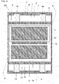
- FIG. 4 is a cross-sectional view of another electrochemical cell module corresponding to FIG. 2 .
- the liquid layer 14 may be located, for example, in an area of overlap between the first electricity generator 2 and the second electricity generator 12. This structure may easily apply pressure uniformly to the first electricity generator 2 and the second electricity generator 12. The electrochemical cell 50 is thus less likely to deteriorate.
- the liquid layer 14 may be formed from, for example, a material having higher heat-conductivity than an electrolyte used in the first electricity generator 2 and the second electricity generator 12. This may facilitate transfer of heat generated in the first unit cell 1 and the second unit cell 11 to the liquid layer 14. The first unit cell 1 and the second unit cell 11 may thus be less likely to accumulate heat.
- the electrochemical cell 50 may thus have a longer service life.
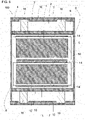
- FIG. 5 is a cross-sectional view of still another electrochemical cell module corresponding to FIG. 2 .
- the liquid layer 14 may be located, for example, at least between the first casing 3 and the outer container 4 or between the second casing 13 and the outer container 4.
- a liquid layer 14 is located between the first casing 3 and the second casing 13, and at a position opposite to the liquid layer 14 with the first electricity generator 2 between them, another liquid layer 14 is located between the first casing 3 and the outer container 4.
- a liquid layer 14 is located between the first casing 3 and the second casing 13, and at a position opposite to the liquid layer 14 with the second electricity generator 12 between them, another liquid layer 14 is located between the second casing 13 and the outer container 4.
- the first unit cell 1 and the second unit cell 11 may thus be less likely to be misaligned in the outer container 4. This reduces the likelihood of damage in the area of contact between the first terminals and the external terminals or between the second terminals and the external terminals.
- the electrochemical cell 50 is thus less likely to be damaged.
- the liquid layer 14 may be formed from, for example, a material having a higher viscosity than the electrolyte used in the first electricity generator 2 and the second electricity generator 12.
- the first unit cell 1 and the second unit cell 11 may thus be less likely to be misaligned in the outer container 4.
- the electrochemical cell 50 is thus still less likely to be damaged.
- FIG. 6 is a cross-sectional view of still another electrochemical cell module corresponding to FIG. 2 .
- the liquid layer 14 may include, for example, a first liquid layer 14a and a second liquid layer 14b.
- the first liquid layer 14a may be located in an area of overlap between the first electricity generator 2 and the second electricity generator 12 as viewed in the stacking direction of the first unit cell 1 and the second unit cell 11.
- the second liquid layer 14b may be located in an area other than an area of overlap between the first electricity generator 2 and the second electricity generator 12.
- the second liquid layer 14b may be thicker than the first liquid layer 14a.
- the thicknesses of the first liquid layer 14a and the second liquid layer 14b are the dimensions in the stacking direction of the first unit cell 1 and the second unit cell 11.
- Such liquid layers reduce transmission of any external force applied perpendicularly in the stacking direction of the first unit cell 1 and the second unit cell 11.
- the electrochemical cell 50 is thus less likely to be damaged.
- the thicknesses of the first liquid layer 14a and the second liquid layer 14b may be measured as described below.
- the electrochemical cell 50 is cooled to a low temperature below the freezing point of the first liquid layer 14a and the second liquid layer 14b to freeze the first liquid layer 14a and the second liquid layer 14b, and then is cut in a direction perpendicular to the main surfaces of the electrochemical cell 50. The cross-sectional surface is observed to determine the thicknesses.
- the thicknesses of the first liquid layer 14a and the second liquid layer 14b may also be ultrasonically measurable.
- FIG. 7 is a cross-sectional view of another electrochemical cell module corresponding to FIG. 2 .
- an electrolyte 18 is located between the first casing 3 and the second casing 13 instead of the liquid layer 14 described above. Similarly to the liquid layer 14, the electrolyte 18 can uniformly apply pressure to the first unit cell 1 and the second unit cell 11. The electrochemical cell 50 may thus be less likely to deteriorate.
- the electrolyte 18 is also located inside the first casing 3 and the second casing 13. The electrolyte 18 between the first casing 3 and the second casing 13 may be the same as the electrolyte included in the first electricity generator 2 and the second electricity generator 12.
- FIG. 8 is a cross-sectional view of still another electrochemical cell module corresponding to FIG. 2 .
- the first casing 3 or the second casing 13 may include an opening 15.
- the opening 15 may be, for example, a cut in at least either the first casing 3 or the second casing 13.
- the opening 15 may also be, for example, a rectangular cut in at least either the first casing 3 or the second casing 13.
- the opening 15 may have, for example, a length of 10 to 200 mm and a width of 10 to 50 mm. Repeated charging and discharging reactions in the first unit cell 1 or the second unit cell 11 may decrease the amount of the electrolyte in the first unit cell 1 or the second unit cell 11.
- the electrolyte 18 between the first casing 3 and the second casing 13 may enter the first casing 3 or the second casing 13 through the opening 15. This reduces the likelihood of the electrolyte in the first unit cell 1 or the second unit cell 11 being depleted.
- the electrochemical cell 50 may thus have a longer service life.
- the opening 15 may be, as viewed perpendicularly in the stacking direction of the first unit cell 1 and the second unit cell 11, in an area other than an area of overlap between the first casing 3 and the first electricity generator 2, or in an area other than an area of overlap between the second casing 13 and the second electricity generator 12. This allows the electrolyte 18 between the first casing 3 and the second casing 13 to more easily enter the first unit cell 1 or the second unit cell 11.
- the electrochemical cell 50 may thus have a longer service life.
- the housing 5 has a space for accommodating the electrochemical cell 50.
- the housing 5 protects the electrochemical cell 50 from the external environment. More specifically, the housing 5 protects the electrochemical cell 50 against an external force received from the external environment.
- the housing 5 is, for example, a box.
- the housing 5 may be formed by, for example, shaping a single member into a rectangular prism.
- the housing 5 may also include, for example, two or more members combined together.
- the housing 5 includes, for example, a metal material. Such a housing 5 has higher rigidity and reduces transmission of any external force from the external environment to the electrochemical cell 50. The housing 5 thus protects the electrochemical cell 50 from the external environment.
- the metal material may be, for example, aluminum or stainless steel. This allows heat generated in the electrochemical cell 50 to easily transfer to the housing 5, thus improving heat dissipation. The electrochemical cell 50 may thus have a longer service life.
- the housing 5 may include, for example, multiple parts.
- the housing 5 may include, for example, two main surface plates 7, two side plates 8, a bottom plate 9, and a terminal cover 6. More specifically, the housing 5 may be formed from a metal material and a resin material in combination.
- the terminal cover 6 protects the external connection terminals of the electrochemical cell 50.
- the terminal cover 6 thus faces the external connection terminals of the electrochemical cell 50.
- the terminal cover 6 may be, for example, rectangular as viewed from the external connection terminals of the electrochemical cell 50.
- the terminal cover 6 may be formed from, for example, a resin material. More specifically, the resin material may be polyethylene terephthalate or polyethylene naphthalate.
- the rectangular bottom surface of the terminal cover 6 as viewed in the direction perpendicular to the surface including the terminals of the electrochemical cell 50 may have, for example, a length of 200 to 600 mm, a width of 50 to 300 mm, and a thickness of 0.1 to 5 mm.
- the rectangular side surfaces of the terminal cover 6 may have, for example, a length of 200 to 600 mm, a width of 50 to 300 mm, and a thickness of 0.1 to 5 mm.
- the main surface plates 7 protect the main surfaces of the electrochemical cell 50.
- the main surface plates 7 thus face the main surfaces of the electrochemical cell 50.
- the main surfaces of the electrochemical cell 50 including the first unit cell 1 and the second unit cell 11 stacked on each other are the surfaces of the outer container 4 extending in a direction intersecting the stacking direction.
- the main surface plates 7 may be rectangular as viewed in the direction perpendicular to the main surfaces of the electrochemical cell 50.
- the main surface plates 7 may be formed from, for example, a metal material. More specifically, the metal material may be, for example, aluminum or stainless steel. Such main surface plates 7 easily transfer heat generated in the electrochemical cell 50 to the outside. The electrochemical cell 50 may thus have a longer service life.
- the main surface plates 7 may be formed from, for example, a resin material.
- the resin material may be, for example, a heat-resistant resin material with a high melting point.
- the heat-resistant resin material may be, for example, polyethylene terephthalate (PET).
- PET polyethylene terephthalate
- Such main surface plates 7 can electrically insulate the electrochemical cell 50 from the external environment, thus reducing the likelihood of a short-circuit forming between the electrochemical cell 50 and the external environment.
- the rectangular main surface plates 7 as viewed in the direction perpendicular to the side surfaces of the electrochemical cell 50 may have, for example, a length of 200 to 600 mm, a width of 50 to 300 mm, and a thickness of 0.5 to 5 mm.
- the side plates 8 protect the side surfaces of the electrochemical cell 50.
- the side plates 8 thus face the side surfaces of the electrochemical cell 50.
- the side plates 8 may also be, for example, in contact with the electrochemical cell 50.
- the side plates 8 may be, for example, rectangular as viewed in the direction perpendicular to the side surfaces of the electrochemical cell 50.
- the side plates 8 may be formed from, for example, a metal material. More specifically, the side plates 8 may be formed from, for example, aluminum or stainless steel. Such side plates 8 easily transfer heat generated in the electrochemical cell 50 to the outside.
- the electrochemical cell 50 may thus have a longer service life.
- the side plates 8 may also be formed from, for example, a resin material.
- the resin material may be, for example, a heat-resistant resin material.
- the heat-resistant resin material may be, for example, PET.
- Such side plates 8 can electrically insulate the electrochemical cell 50 from the external environment, thus reducing the likelihood of a short-circuit forming between the electrochemical cell 50 and the external environment.
- the rectangular side plates 8 as viewed in the direction perpendicular to the side surfaces of the electrochemical cell 50 may have, for example, a length of 200 to 600 mm, a width of 50 to 300 mm, and a thickness of 0.5 to 5 mm.
- the bottom plate 9 protects the surface of the electrochemical cell 50 opposite to the surface from which the external connection terminals protrude.
- the bottom plate 9 may thus be in contact with the surface of the electrochemical cell 50 opposite to the surface from which the external connection terminals protrude.
- the bottom plate 9 may be rectangular as viewed in the direction perpendicular to the surface opposite to the surface from which the external terminals protrude.
- the bottom plate 9 may be formed from, for example, a metal material.
- the metal material may be, for example, aluminum or stainless steel. Such a bottom plate 9 easily transfers heat generated in the electrochemical cell 50 to the outside.
- the battery may thus have a longer service life.
- the bottom plate 9 may also be formed from, for example, a resin material.
- the resin material may be, for example, a heat-resistant resin material.
- the heat-resistant resin material may be, for example, PET.
- Such a bottom plate 9 can electrically insulate the electrochemical cell 50 from the external environment, thus reducing the likelihood of a short-circuit forming between the electrochemical cell 50 and the external environment.
- the bottom plate 9 may also be formed by, for example, bending a part of the side plate 8 or the main surface plate 7.
- the rectangular bottom plate 9 as viewed in the direction perpendicular to the surface of the electrochemical cell 50 opposite to the surface from which the external connection terminals protrude may have, for example, a length of 200 to 600 mm, a width of 50 to 300 mm, and a thickness of 0.5 to 5 mm.
- the electrochemical cell module 100 may include, for example, a pressurizing unit to apply pressure to the main surfaces of the first unit cell 1 and the second unit cell 11 through the outer container 4 in the housing 5.
- a pressurizing unit includes, for example, pressure plates 10 and elastic members.
- the first unit cell 1 and the second unit cell 11 may be pressed and held by, for example, the pressure plates 10 and the elastic members in the housing 5.
- the pressure plates 10 may be movably located between the main surface plates 7 and the electrochemical cell 50 in the housing 5.
- the pressure plates 10 may be formed from, for example, a metal material.
- the metal material may be, for example, aluminum or stainless steel.
- Such pressure plates 10 easily transfer heat generated in the electrochemical cell 50 to the outside.
- the electrochemical cell 50 may thus have a longer service life.
- the pressure plates 10 may also be formed from, for example, a resin material.
- the resin material may be, for example, a thermosetting resin.
- the thermosetting resin may be, for example, an epoxy resin, a phenolic resin, or a melamine resin.
- Such pressure plates 10 can electrically insulate the electrochemical cell 50 from the external environment, thus reducing the likelihood of a short-circuit forming between the electrochemical cell 50 and the external environment.
- the pressure plates 10 may be formed from, for example, a resin material and a metal material. Each pressure plate 10 may include, for example, a portion in contact with the electrochemical cell 50 and formed from a resin material. Such a resin material can electrically insulate the electrochemical cell 50 from the pressure plates 10. This reduces the likelihood of a short-circuit forming between the electrochemical cell 50 and the external environment.
- the pressure plates 10 including a metal material may be less likely to be damaged.
- Each elastic member is located between the pressure plate 10 and the main surface plate 7 in the housing 5.
- the elastic members apply pressure to the pressure plates 10 to apply pressure to the electrochemical cell 50.
- the elastic members may be, for example, springs 16.
- the springs 16 may be helical coil springs.
- the springs 16 may be, for example, leaf springs of bent plates.
- the springs 16 may be formed from, for example, a metal material.
- the metal material may be, for example, steel or stainless steel.
- the springs 16 may have, for example, a diameter of 5 to 50 mm, a length of 10 to 50 mm, and a pitch of 1 to 10 mm.
- the elastic members may be formed from a rubber material.
- the rubber material may be, for example, plate-like.
- the rubber material may have, for example, the same shape as the pressure plate 10.
- the rubber material may include, for example, natural rubber.
- the rubber material may include, for example, synthetic rubber.
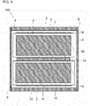
- FIG. 9 is a cross-sectional view of still another electrochemical cell module corresponding to FIG. 2 .
- the main surface plates 7 in the housing 5 may press the outer container 4 to apply pressure to the main surfaces of the first unit cell 1 and the second unit cell 11.
- the main surface plates 7, for example, screwed to the side plates 8 may apply pressure to the main surfaces of the first unit cell 1 and the second unit cell 11.
- FIGs. 1 to 9 show the unit cells, the electricity generators, the casings, or the terminals in the same shape having their outer peripheries aligned with each other.
- the shapes may be slightly different, with the outer peripheries slightly misaligned from each other.
- the outer peripheries may be misaligned within the range of manufacturing errors.
- the housing 5 may accommodate, for example, a stack of two or more electrochemical cells 50, rather than the electrochemical cell 50 alone.
Landscapes
- Chemical & Material Sciences (AREA)
- Chemical Kinetics & Catalysis (AREA)
- Electrochemistry (AREA)
- General Chemical & Material Sciences (AREA)
- Sealing Battery Cases Or Jackets (AREA)
- Battery Mounting, Suspending (AREA)
- Filling, Topping-Up Batteries (AREA)
- Cell Separators (AREA)
Abstract
Description
- The present disclosure relates to an electrochemical cell and an electrochemical cell module.
- A known electrochemical cell module is described in, for example,
Patent Literature 1. The electrochemical cell module described inPatent Literature 1 allows a uniform and stable operation of electrochemical cells and reduces defects such as decreased capacity and gas generation. - Patent Literature 1:
Japanese Unexamined Patent Application Publication No. 2019-21382 - An electrochemical cell according to an aspect of the present disclosure includes a first unit cell, a second unit cell, an outer container, and a liquid layer. The first unit cell includes a first electricity generator and a first casing containing the first electricity generator. The second unit cell includes a second electricity generator and a second casing containing the second electricity generator. The outer container contains the first unit cell and the second unit cell. The liquid layer is located between the first casing and the second casing. The liquid layer is in direct contact with the first casing and the second casing.
- An electrochemical cell according to another aspect of the present disclosure includes a first unit cell, a second unit cell, an outer container, and an electrolyte. The first unit cell includes a first electricity generator and a first casing containing the first electricity generator. The second unit cell includes a second electricity generator and a second casing containing the second electricity generator. The outer container contains the first unit cell and the second unit cell. The electrolyte is located inside the first casing, inside the second casing, and between the first casing and the second casing.
- An electrochemical cell module according to another aspect of the present disclosure includes the electrochemical cell according to one of the above aspects, a housing containing the electrochemical cell, and a pressurizing unit that applies pressure to the first unit cell and the second unit cell.
- An electrochemical cell module according to another aspect of the present disclosure includes the electrochemical cell according to one of the above aspects, and a housing containing the electrochemical cell. The housing applies pressure to the first unit cell and the second unit cell.
- The objects, features, and advantages of the present disclosure will become more apparent from the following detailed description and the drawings.
-
FIG. 1 is a perspective view of an electrochemical cell module. -
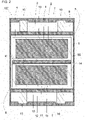
FIG. 2 is a cross-sectional view taken along line II-II inFIG. 1 . -
FIG. 3 is an enlarged view of area III inFIG. 2 . -
FIG. 4 is a cross-sectional view of another electrochemical cell module corresponding toFIG. 2 . -
FIG. 5 is a cross-sectional view of still another electrochemical cell module corresponding toFIG. 2 . -
FIG. 6 is a cross-sectional view of still another electrochemical cell module corresponding toFIG. 2 . -
FIG. 7 is a cross-sectional view of another electrochemical cell module corresponding toFIG. 2 . -
FIG. 8 is a cross-sectional view of still another electrochemical cell module corresponding toFIG. 2 . -
FIG. 9 is a cross-sectional view of still another electrochemical cell module corresponding toFIG. 2 . - An
electrochemical cell module 100 will now be described in detail with reference toFIGs. 1 and2 . As shown inFIGs. 1 and2 , theelectrochemical cell module 100 includes ahousing 5 and anelectrochemical cell 50 located in thehousing 5. Theelectrochemical cell 50 functions as a battery in theelectrochemical cell module 100. Theelectrochemical cell 50 includes, for example, a lithium-ion battery. Theelectrochemical cell 50 includes anouter container 4, afirst unit cell 1 and asecond unit cell 11 in theouter container 4, and aliquid layer 14 between thefirst unit cell 1 and thesecond unit cell 11. Thefirst unit cell 1 and thesecond unit cell 11 may be, for example, held with their main surfaces pressed against each other. Thefirst unit cell 1 and thesecond unit cell 11 may be, for example, stacked on each other in theelectrochemical cell 50. Theelectrochemical cell 50 is, for example, plate-like. Theelectrochemical cell 50 electrically connected to an external device can supply electricity to the external device. - The
first unit cell 1 includes afirst electricity generator 2, afirst casing 3 containing thefirst electricity generator 2, and first terminals. Thefirst unit cell 1 is the smallest unit member functioning as a battery in theelectrochemical cell 50. Thefirst unit cell 1 is, for example, a plate with main surfaces. Thefirst unit cell 1 may be, for example, circular. Thefirst unit cell 1 may also be, for example, rectangular as viewed in a direction perpendicular to the main surfaces of thefirst unit cell 1. Thefirst unit cell 1 may have, for example, a length of 50 to 500 mm, a width of 50 to 300 mm, and a thickness of 0.1 to 2 mm. - The
first electricity generator 2 charges and discharges through an electrochemical reaction. Thefirst electricity generator 2 has, for example, a positive electrode, a negative electrode, and a separator between the positive electrode and the negative electrode. Thefirst electricity generator 2 may exchange cations and anions between the positive electrode and the negative electrode through the separator. Thefirst electricity generator 2 with the positive electrode and the negative electrode electrically connected to an external device can supply electricity to the external device. - The
first electricity generator 2 is, for example, a stack of the positive electrode, the separator, and the negative electrode. Thefirst electricity generator 2 is, for example, plate-like. Thefirst electricity generator 2 has, for example, the positive electrode, the separator, and the negative electrode stacked in the thickness direction of the plate. - The positive electrode and the negative electrode are, for example, electrochemically active. The positive electrode and the negative electrode may include, for example, an active material and an electrolyte. The electrolyte may be, for example, a solvent containing salt or a solvent mixture containing salt.
- More specifically, the positive electrode and the negative electrode may include, for example, the active material and the electrolyte described in
U.S. Provisional Patent Application No. 61/787,382 U.S. Provisional Patent Application No. 61/787,372 - The separator separates the positive electrode and the negative electrode without a short-circuit between them. For example, the separator may have pores for passage of cations and anions. The separator may be formed from, for example, a porous insulating material. More specifically, the separator may be formed from, for example, a polyolefin or polyvinyl chloride.
- The plate-like
first electricity generator 2 may have, for example, a length of 50 to 500 mm, a width of 50 to 300 mm, and a thickness of 0.1 to 2.0 mm. - The
first casing 3 has a space for containing thefirst electricity generator 2. Thefirst casing 3 protects thefirst electricity generator 2 from the external environment. More specifically, thefirst casing 3 electrically insulates thefirst electricity generator 2 from the external environment. Thefirst casing 3 entirely covers thefirst electricity generator 2. - The
first casing 3 is, for example, a flat bag. Thefirst casing 3 is formed from, for example, a laminated film shaped into a flat bag. Thefirst casing 3 may be formed by, for example, welding two laminated films together. Thefirst casing 3 may be, for example, rectangular as viewed in the stacking direction of the positive electrode, the separator, and the negative electrode. - The
first casing 3 includes, for example, an insulating material. Thefirst casing 3 protects thefirst electricity generator 2 from the external environment with no short-circuit forming between the external environment and thefirst electricity generator 2. Thefirst casing 3 includes, for example, a resin material. More specifically, the resin material may be, for example, polyethylene terephthalate or polyethylene. - The
first casing 3 may be, for example, multilayered. More specifically, thefirst casing 3 includes, for example, a thermally adhesive resin material and a heat-resistant resin material. More specifically, the thermally adhesive resin material melts at temperatures lower than 150 °C. More specifically, the heat-resistant resin material melts at 150 to 300 °C. The heat-resistant resin material may include, for example, polyethylene terephthalate or polyethylene naphthalate. The thermally adhesive resin material may be, for example, polyethylene or polypropylene. - The first terminals electrically connect the
first electricity generator 2 to an external device. The first terminals are, for example, plate-like. More specifically, the first terminals are, for example, quadrangular as viewed in the stacking direction of thefirst unit cell 1 and thesecond unit cell 11. The first terminals may be, for example, rectangular. The rectangular first terminals may include, for example, long sides and short sides. - The first terminals are in contact with the
first electricity generator 2 as viewed in the stacking direction of thefirst unit cell 1 and thesecond unit cell 11. The first terminals are on one peripheral side of thefirst electricity generator 2 as viewed in the stacking direction of thefirst unit cell 1 and thesecond unit cell 11. The first terminals protrude outward from thefirst unit cell 1 for electrical connection to the external device. The first terminals electrically connect to external connection terminals outside thefirst unit cell 1. - The first terminals include, for example, a conductive material. The first terminals may include, for example, a metal material. More specifically, the metal material may be, for example, aluminum or copper. The plate-like first terminals may have, for example, a length of 30 to 100 mm, a width of 10 to 100 mm, and a thickness of 0.1 to 0.5 mm.
- The
second unit cell 11 is rechargeable, similarly to thefirst unit cell 1. In theelectrochemical cell 50, thefirst unit cell 1 and thesecond unit cell 11 are connected to each other in parallel. This may increase the capacity of theelectrochemical cell 50. Thefirst unit cell 1 and thesecond unit cell 11 may also be connected to each other in series. This may increase the voltage across theelectrochemical cell 50. - The
second unit cell 11 and thefirst unit cell 1 are, for example, stacked on each other in theouter container 4. Thesecond unit cell 11 includes asecond electricity generator 12, asecond casing 13, and second terminals. Thesecond unit cell 11 has the same shape as thefirst unit cell 1 in theelectrochemical cell 50. Thesecond unit cell 11 may be shaped, for example, differently from thefirst unit cell 1. Thesecond unit cell 11 is stacked on thefirst unit cell 1 with their outer peripheries aligned with each other in theelectrochemical cell 50. Thesecond unit cell 11 may also be stacked on thefirst unit cell 1 without their outer peripheries being aligned with each other. - The
first electricity generator 2 and thesecond electricity generator 12 are stacked on each other with their long sides aligned and their short sides aligned as viewed in the stacking direction of thefirst unit cell 1 and thesecond unit cell 11. Thefirst casing 3 and thesecond casing 13 are stacked on each other with their long sides aligned and their short sides aligned as viewed in the stacking direction of thefirst unit cell 1 and thesecond unit cell 11. The first terminals and the second terminals are stacked on one another with their long sides aligned and their short sides aligned as viewed in the stacking direction of thefirst unit cell 1 and thesecond unit cell 11. - The
second electricity generator 12 may be formed from, for example, the material included in thefirst electricity generator 2. More specifically, thesecond electricity generator 12 may be formed from the same material as for thefirst electricity generator 2. Thesecond electricity generator 12 may also be formed from, for example, a material different from the material for thefirst electricity generator 2. - The
second casing 13 has the same shape as thefirst casing 3. Thesecond casing 13 may be shaped, for example, differently from thefirst casing 3. Thesecond casing 13 may be formed from, for example, the material included in thefirst casing 3. More specifically, thesecond casing 13 may be formed from the same material as for thefirst casing 3. Thesecond casing 13 may also be formed from, for example, a material different from the material for thefirst casing 3. - The second terminals have the same shape as the first terminals. The second terminals may be shaped, for example, differently from the first terminals. The second terminals may be formed from, for example, the material included in the first terminals. More specifically, the second terminals may be formed from the same material as for the first terminals. The second terminals may also be formed from, for example, a material different from the material for the first terminals.
- The
second unit cell 11 may have, for example, the same dimensions as thefirst unit cell 1. Thesecond unit cell 11 may also have, for example, dimensions different from the dimensions of thefirst unit cell 1. - The
outer container 4 has a space for containing thefirst unit cell 1 and thesecond unit cell 11. Theouter container 4 protects thefirst unit cell 1 and thesecond unit cell 11 from the external environment. More specifically, theouter container 4 protects thefirst unit cell 1 and thesecond unit cell 11 from oxygen and moisture contained in the atmosphere. - The
outer container 4 may be, for example, cylindrical. Theouter container 4 may also be, for example, a rectangular prism. Theouter container 4 may also be, for example, a bag. Theouter container 4 is formed from, for example, a single member shaped into a bag. Theouter container 4 may also be formed by, for example, welding two members together. Theouter container 4 may be, for example, rectangular as viewed in the stacking direction of thefirst unit cell 1 and thesecond unit cell 11. Theouter container 4 may transmit external pressure applied through a pressurizing unit to the inside as described later. - The
outer container 4 includes, for example, an insulating material. Theouter container 4 thus reduces the likelihood of a short-circuit forming between the external environment and thefirst unit cell 1 or thesecond unit cell 11 and protects thefirst unit cell 1 and thesecond unit cell 11 from the external environment. The insulating material may be, for example, a resin material. More specifically, the resin material may be, for example, polyethylene terephthalate or polyethylene. - The
outer container 4 may be, for example, multilayered. Theouter container 4 may also be, for example, three-layered. More specifically, theouter container 4 may include, for example, a first insulating layer, a moisture-proof layer, and a second insulating layer. The moisture-proof layer is, for example, located between the first insulating layer and the second insulating layer. More specifically, the moisture-proof layer may also be covered with, for example, the first insulating layer and the second insulating layer. The moisture-proof layer may also be in direct contact with, for example, the first insulating layer and the second insulating layer. - The first insulating layer includes, for example, a resin material. More specifically, the resin material may be, for example, polyethylene terephthalate or polyethylene naphthalate. The moisture-proof layer prevents oxygen and moisture penetrating a first resin layer from reaching a second resin layer. The moisture-proof layer includes, for example, a metal material. More specifically, the metal material may be, for example, aluminum or copper. The second resin layer includes, for example, a resin material. More specifically, the resin material may be, for example, polyethylene or polypropylene.
- The
outer container 4 including the moisture-proof layer protects thefirst unit cell 1 and thesecond unit cell 11 from oxygen and moisture penetrating the first resin layer. Thefirst unit cell 1 and thesecond unit cell 11 are thus less likely to deteriorate. Theelectrochemical cell 50 is thus less likely to be damaged. - The rectangular
outer container 4 as viewed in the stacking direction of thefirst unit cell 1 and thesecond unit cell 11 may have, for example, a length of 50 to 600 mm, a width of 50 to 400 mm, and a thickness of 1 to 50 mm. - Known unit cells may have varying thicknesses due to manufacturing errors. In addition, repeated charging and discharging reactions in an electrochemical cell module may expand and contract its positive electrodes and negative electrodes, and may generate gas, causing the unit cells to have varying thicknesses. Such unit cells cannot receive pressure uniformly, possibly increasing the interface resistance between the electricity generators. The increased interface resistance may disable uniform charging and discharging reactions in the unit cells, possibly causing the unit cells to deteriorate further.
- The
liquid layer 14 transmits external pressure to thefirst unit cell 1 and thesecond unit cell 11. Theliquid layer 14 is located at least between thefirst unit cell 1 and thesecond unit cell 11. Theliquid layer 14 is in direct contact with thefirst unit cell 1 and thesecond unit cell 11. More specifically, theliquid layer 14 is located between the surface of thefirst casing 3 in thefirst unit cell 1 and the surface of thesecond casing 13 in thesecond unit cell 11 facing thefirst casing 3. Theliquid layer 14 may fill, for example, the space between thefirst casing 3 in thefirst unit cell 1 and thesecond casing 13 in thesecond unit cell 11 facing thefirst casing 3. Although thefirst unit cell 1 and thesecond unit cell 11 with varying thicknesses may have recesses on their surfaces, theliquid layer 14 may be located inside the recesses to allow pressure to be applied uniformly to the main surfaces of thefirst unit cell 1 and thesecond unit cell 11. The main surfaces of thefirst unit cell 1 and thesecond unit cell 11 stacked on each other in theelectrochemical cell 50 extend in a direction intersecting the stacking direction. The main surfaces of thefirst unit cell 1 and thesecond unit cell 11 may include the surfaces of thefirst casing 3 in thefirst unit cell 1 and thesecond casing 13 in thesecond unit cell 11 facing each other with theliquid layer 14 between them. This structure allows thefirst unit cell 1 and thesecond unit cell 11 to perform charging and discharging reactions without varying interface resistances. Thefirst unit cell 1 and thesecond unit cell 11 are thus less likely to deteriorate. Theelectrochemical cell 50 may thus have a longer service life. - The
liquid layer 14 is a layer of liquid material located between thefirst casing 3 and thesecond casing 13 and in direct contact with thefirst casing 3 and thesecond casing 13. - The
liquid layer 14 may include, for example, an organic solvent. More specifically, the organic solvent may be, for example, ethylene carbonate or γ-butyrolactone. Theliquid layer 14 may also include a flowable low-molecular-weight polymeric material. More specifically, the flowable polymeric material may be, for example, polyethylene oxide. Theliquid layer 14 may be formed from a silicon-based polymer material. The silicon-based polymer material may be, for example, silicone. - The
liquid layer 14 may be formed from a water-absorbent material. Such an absorbent material absorbs external moisture entering theouter container 4 and reduces moisture entering thefirst unit cell 1 and thesecond unit cell 11. Theelectrochemical cell 50 may thus have a longer service life. The water-absorbent material may be, for example, a water-absorbent polymer. The water-absorbent polymer may be, for example, polyacrylonitrile. - The
liquid layer 14 may include an inorganic material. As shown inFIG. 3 , the inorganic material may be dispersed as afiller 17 in the liquid material for theliquid layer 14. The inorganic material may include, for example, aporous filler 17. Theporous filler 17 may be, for example, zeolite. Zeolite can absorb any moisture entering theouter container 4. Theelectrochemical cell 50 can thus have a longer service life. Theliquid layer 14 may include, for example, 0.1 to 10% by weight of inorganic material. - The inorganic material may be, for example, a
metal filler 17. Themetal filler 17 may react with, for example, water and oxygen. More specifically, themetal filler 17 may be, for example, iron, copper, or aluminum. Water and oxygen entering theouter container 4 may react with themetal filler 17 and thus be less likely to enter thefirst unit cell 1 and thesecond unit cell 11. Theelectrochemical cell 50 may thus have a longer service life. Theliquid layer 14 may have a thickness of, for example, 1 to 100 µm. - When the
first unit cell 1 and thesecond unit cell 11 are stacked on each other, theliquid layer 14 may be, for example, placed on thefirst casing 3 of thefirst unit cell 1, and then thesecond casing 13 may be placed on theliquid layer 14. Theliquid layer 14 may also be, for example, placed on thesecond casing 13 of thesecond unit cell 11, and then thefirst casing 3 may be placed on theliquid layer 14. Theliquid layer 14 may be, for example, placed between thefirst unit cell 1 and thesecond unit cell 11 when thefirst unit cell 1 and thesecond unit cell 11 are placed in theouter container 4 in theelectrochemical cell 50 and theouter container 4 is closed. -
FIG. 4 is a cross-sectional view of another electrochemical cell module corresponding toFIG. 2 . As viewed in the stacking direction of thefirst unit cell 1 and thesecond unit cell 11, theliquid layer 14 may be located, for example, in an area of overlap between thefirst electricity generator 2 and thesecond electricity generator 12. This structure may easily apply pressure uniformly to thefirst electricity generator 2 and thesecond electricity generator 12. Theelectrochemical cell 50 is thus less likely to deteriorate. - The
liquid layer 14 may be formed from, for example, a material having higher heat-conductivity than an electrolyte used in thefirst electricity generator 2 and thesecond electricity generator 12. This may facilitate transfer of heat generated in thefirst unit cell 1 and thesecond unit cell 11 to theliquid layer 14. Thefirst unit cell 1 and thesecond unit cell 11 may thus be less likely to accumulate heat. Theelectrochemical cell 50 may thus have a longer service life. -
FIG. 5 is a cross-sectional view of still another electrochemical cell module corresponding toFIG. 2 . As shown inFIG. 5 , theliquid layer 14 may be located, for example, at least between thefirst casing 3 and theouter container 4 or between thesecond casing 13 and theouter container 4. In the example shown inFIG. 5 , aliquid layer 14 is located between thefirst casing 3 and thesecond casing 13, and at a position opposite to theliquid layer 14 with thefirst electricity generator 2 between them, anotherliquid layer 14 is located between thefirst casing 3 and theouter container 4. Aliquid layer 14 is located between thefirst casing 3 and thesecond casing 13, and at a position opposite to theliquid layer 14 with thesecond electricity generator 12 between them, anotherliquid layer 14 is located between thesecond casing 13 and theouter container 4. Thefirst unit cell 1 and thesecond unit cell 11 may thus be less likely to be misaligned in theouter container 4. This reduces the likelihood of damage in the area of contact between the first terminals and the external terminals or between the second terminals and the external terminals. Theelectrochemical cell 50 is thus less likely to be damaged. - The
liquid layer 14 may be formed from, for example, a material having a higher viscosity than the electrolyte used in thefirst electricity generator 2 and thesecond electricity generator 12. Thefirst unit cell 1 and thesecond unit cell 11 may thus be less likely to be misaligned in theouter container 4. Theelectrochemical cell 50 is thus still less likely to be damaged. -
FIG. 6 is a cross-sectional view of still another electrochemical cell module corresponding toFIG. 2 . As shown inFIG. 6 , theliquid layer 14 may include, for example, afirst liquid layer 14a and asecond liquid layer 14b. Thefirst liquid layer 14a may be located in an area of overlap between thefirst electricity generator 2 and thesecond electricity generator 12 as viewed in the stacking direction of thefirst unit cell 1 and thesecond unit cell 11. Thesecond liquid layer 14b may be located in an area other than an area of overlap between thefirst electricity generator 2 and thesecond electricity generator 12. Thesecond liquid layer 14b may be thicker than thefirst liquid layer 14a. The thicknesses of thefirst liquid layer 14a and thesecond liquid layer 14b are the dimensions in the stacking direction of thefirst unit cell 1 and thesecond unit cell 11. Such liquid layers reduce transmission of any external force applied perpendicularly in the stacking direction of thefirst unit cell 1 and thesecond unit cell 11. Theelectrochemical cell 50 is thus less likely to be damaged. - The thicknesses of the
first liquid layer 14a and thesecond liquid layer 14b may be measured as described below. Theelectrochemical cell 50 is cooled to a low temperature below the freezing point of thefirst liquid layer 14a and thesecond liquid layer 14b to freeze thefirst liquid layer 14a and thesecond liquid layer 14b, and then is cut in a direction perpendicular to the main surfaces of theelectrochemical cell 50. The cross-sectional surface is observed to determine the thicknesses. The thicknesses of thefirst liquid layer 14a and thesecond liquid layer 14b may also be ultrasonically measurable. - Other embodiments of the present disclosure will now be described.
FIG. 7 is a cross-sectional view of another electrochemical cell module corresponding toFIG. 2 . In the present embodiment, as shown inFIG. 7 , anelectrolyte 18 is located between thefirst casing 3 and thesecond casing 13 instead of theliquid layer 14 described above. Similarly to theliquid layer 14, theelectrolyte 18 can uniformly apply pressure to thefirst unit cell 1 and thesecond unit cell 11. Theelectrochemical cell 50 may thus be less likely to deteriorate. Theelectrolyte 18 is also located inside thefirst casing 3 and thesecond casing 13. Theelectrolyte 18 between thefirst casing 3 and thesecond casing 13 may be the same as the electrolyte included in thefirst electricity generator 2 and thesecond electricity generator 12. -
FIG. 8 is a cross-sectional view of still another electrochemical cell module corresponding toFIG. 2 . As shown inFIG. 8 , at least either thefirst casing 3 or thesecond casing 13 may include anopening 15. Theopening 15 may be, for example, a cut in at least either thefirst casing 3 or thesecond casing 13. Theopening 15 may also be, for example, a rectangular cut in at least either thefirst casing 3 or thesecond casing 13. Theopening 15 may have, for example, a length of 10 to 200 mm and a width of 10 to 50 mm. Repeated charging and discharging reactions in thefirst unit cell 1 or thesecond unit cell 11 may decrease the amount of the electrolyte in thefirst unit cell 1 or thesecond unit cell 11. In this case, theelectrolyte 18 between thefirst casing 3 and thesecond casing 13 may enter thefirst casing 3 or thesecond casing 13 through theopening 15. This reduces the likelihood of the electrolyte in thefirst unit cell 1 or thesecond unit cell 11 being depleted. Theelectrochemical cell 50 may thus have a longer service life. - The
opening 15 may be, as viewed perpendicularly in the stacking direction of thefirst unit cell 1 and thesecond unit cell 11, in an area other than an area of overlap between thefirst casing 3 and thefirst electricity generator 2, or in an area other than an area of overlap between thesecond casing 13 and thesecond electricity generator 12. This allows theelectrolyte 18 between thefirst casing 3 and thesecond casing 13 to more easily enter thefirst unit cell 1 or thesecond unit cell 11. Theelectrochemical cell 50 may thus have a longer service life. - The
housing 5 has a space for accommodating theelectrochemical cell 50. Thehousing 5 protects theelectrochemical cell 50 from the external environment. More specifically, thehousing 5 protects theelectrochemical cell 50 against an external force received from the external environment. Thehousing 5 is, for example, a box. Thehousing 5 may be formed by, for example, shaping a single member into a rectangular prism. Thehousing 5 may also include, for example, two or more members combined together. - The
housing 5 includes, for example, a metal material. Such ahousing 5 has higher rigidity and reduces transmission of any external force from the external environment to theelectrochemical cell 50. Thehousing 5 thus protects theelectrochemical cell 50 from the external environment. The metal material may be, for example, aluminum or stainless steel. This allows heat generated in theelectrochemical cell 50 to easily transfer to thehousing 5, thus improving heat dissipation. Theelectrochemical cell 50 may thus have a longer service life. - The
housing 5 may include, for example, multiple parts. Thehousing 5 may include, for example, twomain surface plates 7, twoside plates 8, abottom plate 9, and aterminal cover 6. More specifically, thehousing 5 may be formed from a metal material and a resin material in combination. - The
terminal cover 6 protects the external connection terminals of theelectrochemical cell 50. Theterminal cover 6 thus faces the external connection terminals of theelectrochemical cell 50. Theterminal cover 6 may be, for example, rectangular as viewed from the external connection terminals of theelectrochemical cell 50. Theterminal cover 6 may be formed from, for example, a resin material. More specifically, the resin material may be polyethylene terephthalate or polyethylene naphthalate. The rectangular bottom surface of theterminal cover 6 as viewed in the direction perpendicular to the surface including the terminals of theelectrochemical cell 50 may have, for example, a length of 200 to 600 mm, a width of 50 to 300 mm, and a thickness of 0.1 to 5 mm. The rectangular side surfaces of theterminal cover 6 may have, for example, a length of 200 to 600 mm, a width of 50 to 300 mm, and a thickness of 0.1 to 5 mm. - The
main surface plates 7 protect the main surfaces of theelectrochemical cell 50. Themain surface plates 7 thus face the main surfaces of theelectrochemical cell 50. The main surfaces of theelectrochemical cell 50 including thefirst unit cell 1 and thesecond unit cell 11 stacked on each other are the surfaces of theouter container 4 extending in a direction intersecting the stacking direction. Themain surface plates 7 may be rectangular as viewed in the direction perpendicular to the main surfaces of theelectrochemical cell 50. Themain surface plates 7 may be formed from, for example, a metal material. More specifically, the metal material may be, for example, aluminum or stainless steel. Suchmain surface plates 7 easily transfer heat generated in theelectrochemical cell 50 to the outside. Theelectrochemical cell 50 may thus have a longer service life. - The
main surface plates 7 may be formed from, for example, a resin material. The resin material may be, for example, a heat-resistant resin material with a high melting point. The heat-resistant resin material may be, for example, polyethylene terephthalate (PET). Suchmain surface plates 7 can electrically insulate theelectrochemical cell 50 from the external environment, thus reducing the likelihood of a short-circuit forming between theelectrochemical cell 50 and the external environment. The rectangularmain surface plates 7 as viewed in the direction perpendicular to the side surfaces of theelectrochemical cell 50 may have, for example, a length of 200 to 600 mm, a width of 50 to 300 mm, and a thickness of 0.5 to 5 mm. - The
side plates 8 protect the side surfaces of theelectrochemical cell 50. Theside plates 8 thus face the side surfaces of theelectrochemical cell 50. Theside plates 8 may also be, for example, in contact with theelectrochemical cell 50. Theside plates 8 may be, for example, rectangular as viewed in the direction perpendicular to the side surfaces of theelectrochemical cell 50. Theside plates 8 may be formed from, for example, a metal material. More specifically, theside plates 8 may be formed from, for example, aluminum or stainless steel.Such side plates 8 easily transfer heat generated in theelectrochemical cell 50 to the outside. Theelectrochemical cell 50 may thus have a longer service life. - The
side plates 8 may also be formed from, for example, a resin material. The resin material may be, for example, a heat-resistant resin material. The heat-resistant resin material may be, for example, PET.Such side plates 8 can electrically insulate theelectrochemical cell 50 from the external environment, thus reducing the likelihood of a short-circuit forming between theelectrochemical cell 50 and the external environment. Therectangular side plates 8 as viewed in the direction perpendicular to the side surfaces of theelectrochemical cell 50 may have, for example, a length of 200 to 600 mm, a width of 50 to 300 mm, and a thickness of 0.5 to 5 mm. - The
bottom plate 9 protects the surface of theelectrochemical cell 50 opposite to the surface from which the external connection terminals protrude. Thebottom plate 9 may thus be in contact with the surface of theelectrochemical cell 50 opposite to the surface from which the external connection terminals protrude. Thebottom plate 9 may be rectangular as viewed in the direction perpendicular to the surface opposite to the surface from which the external terminals protrude. Thebottom plate 9 may be formed from, for example, a metal material. The metal material may be, for example, aluminum or stainless steel. Such abottom plate 9 easily transfers heat generated in theelectrochemical cell 50 to the outside. - The battery may thus have a longer service life.
- The
bottom plate 9 may also be formed from, for example, a resin material. The resin material may be, for example, a heat-resistant resin material. The heat-resistant resin material may be, for example, PET. Such abottom plate 9 can electrically insulate theelectrochemical cell 50 from the external environment, thus reducing the likelihood of a short-circuit forming between theelectrochemical cell 50 and the external environment. Thebottom plate 9 may also be formed by, for example, bending a part of theside plate 8 or themain surface plate 7. Therectangular bottom plate 9 as viewed in the direction perpendicular to the surface of theelectrochemical cell 50 opposite to the surface from which the external connection terminals protrude may have, for example, a length of 200 to 600 mm, a width of 50 to 300 mm, and a thickness of 0.5 to 5 mm. - In the examples described above, the
electrochemical cell module 100 may include, for example, a pressurizing unit to apply pressure to the main surfaces of thefirst unit cell 1 and thesecond unit cell 11 through theouter container 4 in thehousing 5. Such a pressurizing unit includes, for example,pressure plates 10 and elastic members. Thefirst unit cell 1 and thesecond unit cell 11 may be pressed and held by, for example, thepressure plates 10 and the elastic members in thehousing 5. To apply pressure to theelectrochemical cell 50, thepressure plates 10 may be movably located between themain surface plates 7 and theelectrochemical cell 50 in thehousing 5. - The
pressure plates 10 may be formed from, for example, a metal material. The metal material may be, for example, aluminum or stainless steel.Such pressure plates 10 easily transfer heat generated in theelectrochemical cell 50 to the outside. Theelectrochemical cell 50 may thus have a longer service life. - The
pressure plates 10 may also be formed from, for example, a resin material. The resin material may be, for example, a thermosetting resin. The thermosetting resin may be, for example, an epoxy resin, a phenolic resin, or a melamine resin.Such pressure plates 10 can electrically insulate theelectrochemical cell 50 from the external environment, thus reducing the likelihood of a short-circuit forming between theelectrochemical cell 50 and the external environment. - The
pressure plates 10 may be formed from, for example, a resin material and a metal material. Eachpressure plate 10 may include, for example, a portion in contact with theelectrochemical cell 50 and formed from a resin material. Such a resin material can electrically insulate theelectrochemical cell 50 from thepressure plates 10. This reduces the likelihood of a short-circuit forming between theelectrochemical cell 50 and the external environment. Thepressure plates 10 including a metal material may be less likely to be damaged. - Each elastic member is located between the
pressure plate 10 and themain surface plate 7 in thehousing 5. The elastic members apply pressure to thepressure plates 10 to apply pressure to theelectrochemical cell 50. The elastic members may be, for example, springs 16. Thesprings 16 may be helical coil springs. Thesprings 16 may be, for example, leaf springs of bent plates. Thesprings 16 may be formed from, for example, a metal material. The metal material may be, for example, steel or stainless steel. Thesprings 16 may have, for example, a diameter of 5 to 50 mm, a length of 10 to 50 mm, and a pitch of 1 to 10 mm. - The elastic members may be formed from a rubber material. The rubber material may be, for example, plate-like. The rubber material may have, for example, the same shape as the
pressure plate 10. The rubber material may include, for example, natural rubber. The rubber material may include, for example, synthetic rubber. - Without the pressurizing unit described above, the
housing 5 may apply pressure to the main surfaces of thefirst unit cell 1 and thesecond unit cell 11 through theouter container 4.FIG. 9 is a cross-sectional view of still another electrochemical cell module corresponding toFIG. 2 . As shown inFIG. 9 , for example, themain surface plates 7 in thehousing 5 may press theouter container 4 to apply pressure to the main surfaces of thefirst unit cell 1 and thesecond unit cell 11. In thehousing 5, themain surface plates 7, for example, screwed to theside plates 8 may apply pressure to the main surfaces of thefirst unit cell 1 and thesecond unit cell 11. - For ease of explanation,
FIGs. 1 to 9 show the unit cells, the electricity generators, the casings, or the terminals in the same shape having their outer peripheries aligned with each other. However, the shapes may be slightly different, with the outer peripheries slightly misaligned from each other. For example, the outer peripheries may be misaligned within the range of manufacturing errors. Thehousing 5 may accommodate, for example, a stack of two or moreelectrochemical cells 50, rather than theelectrochemical cell 50 alone. - The present disclosure may be embodied in various forms without departing from the spirit or the main features of the present disclosure. The embodiments described above are thus merely illustrative in all respects. The scope of the present disclosure is defined not by the description given above but by the claims. Any modifications and alterations contained in the claims fall within the scope of the present invention.
-
- 1
- first unit cell
- 2
- first electricity generator
- 3
- first casing
- 4
- outer container
- 5
- housing
- 6
- terminal cover
- 7
- main surface plate
- 8
- side plate
- 9
- bottom plate
- 10
- pressure plate
- 11
- second unit cell
- 12
- second electricity generator
- 13
- second casing
- 14
- liquid layer
- 14a
- first liquid layer
- 14b
- second liquid layer
- 15
- opening
- 16
- spring
- 17
- filler
- 18
- electrolyte
- 50
- electrochemical cell
- 100
- electrochemical cell module
Claims (7)
- An electrochemical cell, comprising:a first unit cell including a first electricity generator and a first casing, the first casing containing the first electricity generator;a second unit cell including a second electricity generator and a second casing, the second casing containing the second electricity generator;an outer container containing the first unit cell and the second unit cell; anda liquid layer between the first casing and the second casing, the liquid layer being in direct contact with the first casing and the second casing.
- The electrochemical cell according to claim 1, wherein
the liquid layer is located between the outer container and at least one of the first casing or the second casing. - The electrochemical cell according to claim 1 or claim 2, whereinthe first unit cell and the second unit cell are stacked on each other in a direction,the liquid layer includes a first liquid layer in an area of overlap between the first electricity generator and the second electricity generator and a second liquid layer in an area other than the area of overlap between the first electricity generator and the second electricity generator as viewed in the direction, andthe second liquid layer is thicker than the first liquid layer.
- An electrochemical cell, comprising:a first unit cell including a first electricity generator and a first casing, the first casing containing the first electricity generator;a second unit cell including a second electricity generator and a second casing, the second casing containing the second electricity generator;an outer container containing the first unit cell and the second unit cell; andan electrolyte inside the first casing, inside the second casing, and between the first casing and the second casing.
- The electrochemical cell according to claim 4, wherein
at least one of the first casing or the second casing has an opening. - An electrochemical cell module, comprising:the electrochemical cell according to any one of claims 1 to 5;a housing containing the electrochemical cell; anda pressurizing unit configured to apply pressure to the first unit cell and the second unit cell.
- An electrochemical cell module, comprising:the electrochemical cell according to any one of claims 1 to 5; anda housing containing the electrochemical cell,wherein the housing applies pressure to the first unit cell and the second unit cell.
Applications Claiming Priority (2)
| Application Number | Priority Date | Filing Date | Title |
|---|---|---|---|
| JP2019138989 | 2019-07-29 | ||
| PCT/JP2020/028862 WO2021020383A1 (en) | 2019-07-29 | 2020-07-28 | Electrochemical cell and electrochemical cell module |
Publications (2)
| Publication Number | Publication Date |
|---|---|
| EP4007048A1 true EP4007048A1 (en) | 2022-06-01 |
| EP4007048A4 EP4007048A4 (en) | 2024-06-05 |
Family
ID=74229170
Family Applications (1)
| Application Number | Title | Priority Date | Filing Date |
|---|---|---|---|
| EP20848568.0A Pending EP4007048A4 (en) | 2019-07-29 | 2020-07-28 | BATTERY CELL AND BATTERY CELL MODULE |
Country Status (5)
| Country | Link |
|---|---|
| US (1) | US12237523B2 (en) |
| EP (1) | EP4007048A4 (en) |
| JP (3) | JPWO2021020383A1 (en) |
| CN (1) | CN114144925A (en) |
| WO (1) | WO2021020383A1 (en) |
Family Cites Families (12)
| Publication number | Priority date | Publication date | Assignee | Title |
|---|---|---|---|---|
| JP3544142B2 (en) * | 1999-03-31 | 2004-07-21 | 株式会社東芝 | Lithium ion secondary battery |
| JPWO2007043392A1 (en) * | 2005-10-03 | 2009-04-16 | Tdkラムダ株式会社 | Battery pack |
| US20140170468A1 (en) | 2011-07-13 | 2014-06-19 | Toyota Jidosha Kabushiki Kaisha | Battery module |
| JP2013045555A (en) * | 2011-08-23 | 2013-03-04 | Toyota Motor Corp | Battery module |
| US20150288037A1 (en) * | 2014-04-02 | 2015-10-08 | Hamilton Sundstrand Corporation | Insulating liquid immersed battery |
| JP6217987B2 (en) * | 2015-06-15 | 2017-10-25 | トヨタ自動車株式会社 | Assembled battery |
| JP6749804B2 (en) * | 2015-07-15 | 2020-09-02 | セイコーインスツル株式会社 | Electrochemical cell |
| JP6810634B2 (en) * | 2017-02-24 | 2021-01-06 | 株式会社エンビジョンAescジャパン | Battery module and battery system |
| JP6960787B2 (en) | 2017-07-11 | 2021-11-05 | 日産自動車株式会社 | battery |
| JP6987569B2 (en) * | 2017-08-09 | 2022-01-05 | 三菱重工業株式会社 | All solid state battery module |
| GB2568957B (en) * | 2017-12-04 | 2020-06-03 | Jaguar Land Rover Ltd | An electricity storage system, a vehicle, a method and an electronic control means |
| CA3109523A1 (en) * | 2018-08-30 | 2020-03-05 | Hydro-Quebec | Rechargeable battery with ionic liquid electrolyte and electrode pressure |
-
2020
- 2020-07-28 US US17/630,487 patent/US12237523B2/en active Active
- 2020-07-28 CN CN202080052867.5A patent/CN114144925A/en active Pending
- 2020-07-28 EP EP20848568.0A patent/EP4007048A4/en active Pending
- 2020-07-28 JP JP2021535351A patent/JPWO2021020383A1/ja active Pending
- 2020-07-28 WO PCT/JP2020/028862 patent/WO2021020383A1/en not_active Ceased
-
2023
- 2023-11-21 JP JP2023197761A patent/JP7759370B2/en active Active
-
2025
- 2025-07-01 JP JP2025111768A patent/JP2025148385A/en active Pending
Also Published As
| Publication number | Publication date |
|---|---|
| JP2024023362A (en) | 2024-02-21 |
| JP2025148385A (en) | 2025-10-07 |
| US20220255171A1 (en) | 2022-08-11 |
| JP7759370B2 (en) | 2025-10-23 |
| JPWO2021020383A1 (en) | 2021-02-04 |
| WO2021020383A1 (en) | 2021-02-04 |
| EP4007048A4 (en) | 2024-06-05 |
| CN114144925A (en) | 2022-03-04 |
| US12237523B2 (en) | 2025-02-25 |
Similar Documents
| Publication | Publication Date | Title |
|---|---|---|
| KR101057869B1 (en) | Battery pack, battery manufacturing method and vehicle with battery pack | |
| KR101089086B1 (en) | Battery cartridge and battery module including same | |
| KR101560217B1 (en) | Battery Module of Improved Cooling Efficiency | |
| KR102051109B1 (en) | Battery Module | |
| US10135047B2 (en) | Battery pack | |
| US9887404B2 (en) | Secondary battery | |
| US20150303425A1 (en) | Secondary battery module | |
| JP5531220B2 (en) | Stacked battery and stacked battery system | |
| KR20190078841A (en) | Battery module with improved cooling structure | |
| KR101530803B1 (en) | Secondary battery | |
| US12249682B2 (en) | Electrochemical cell module | |
| KR20190069872A (en) | Battery module with improved cooling efficiency and Battery pack comprising the same | |
| JPWO2019187939A1 (en) | Solid state battery module | |
| US20220352541A1 (en) | Electrochemical cell module | |
| US12237523B2 (en) | Electrochemical cell and electrochemical cell module | |
| EP3413393A1 (en) | Electrode assembly for a battery module | |
| KR101637896B1 (en) | Electrode Assembly with Liquid Materials Receiver for Insulation | |
| KR102001545B1 (en) | Battery Cell for Secondary Battery and Battery Module having the same | |
| EP4528913A1 (en) | Secondary battery | |
| JP7358507B2 (en) | electrochemical cell | |
| KR101735805B1 (en) | Battery Cell Comprising the Cell Case Having a Thermally-Welded Portion Bent | |
| KR20230170553A (en) | Temperature sensing assembly and battery module including the same |
Legal Events
| Date | Code | Title | Description |
|---|---|---|---|
| STAA | Information on the status of an ep patent application or granted ep patent |
Free format text: STATUS: THE INTERNATIONAL PUBLICATION HAS BEEN MADE |
|
| PUAI | Public reference made under article 153(3) epc to a published international application that has entered the european phase |
Free format text: ORIGINAL CODE: 0009012 |
|
| STAA | Information on the status of an ep patent application or granted ep patent |
Free format text: STATUS: REQUEST FOR EXAMINATION WAS MADE |
|
| 17P | Request for examination filed |
Effective date: 20220127 |
|
| AK | Designated contracting states |
Kind code of ref document: A1 Designated state(s): AL AT BE BG CH CY CZ DE DK EE ES FI FR GB GR HR HU IE IS IT LI LT LU LV MC MK MT NL NO PL PT RO RS SE SI SK SM TR |
|
| DAV | Request for validation of the european patent (deleted) | ||
| DAX | Request for extension of the european patent (deleted) | ||
| P01 | Opt-out of the competence of the unified patent court (upc) registered |
Effective date: 20230505 |
|
| A4 | Supplementary search report drawn up and despatched |
Effective date: 20240507 |
|
| RIC1 | Information provided on ipc code assigned before grant |
Ipc: H01M 50/20 20210101AFI20240430BHEP |