EP4006925A1 - Cooling system for a transformer and a method of cooling a transformer - Google Patents
Cooling system for a transformer and a method of cooling a transformer Download PDFInfo
- Publication number
- EP4006925A1 EP4006925A1 EP21202730.4A EP21202730A EP4006925A1 EP 4006925 A1 EP4006925 A1 EP 4006925A1 EP 21202730 A EP21202730 A EP 21202730A EP 4006925 A1 EP4006925 A1 EP 4006925A1
- Authority
- EP
- European Patent Office
- Prior art keywords
- cooling
- side wall
- cooling channel
- fluidically connected
- housing
- Prior art date
- Legal status (The legal status is an assumption and is not a legal conclusion. Google has not performed a legal analysis and makes no representation as to the accuracy of the status listed.)
- Granted
Links
Images



Classifications
-
- H—ELECTRICITY
- H01—ELECTRIC ELEMENTS
- H01F—MAGNETS; INDUCTANCES; TRANSFORMERS; SELECTION OF MATERIALS FOR THEIR MAGNETIC PROPERTIES
- H01F27/00—Details of transformers or inductances, in general
- H01F27/02—Casings
- H01F27/025—Constructional details relating to cooling
-
- H—ELECTRICITY
- H01—ELECTRIC ELEMENTS
- H01F—MAGNETS; INDUCTANCES; TRANSFORMERS; SELECTION OF MATERIALS FOR THEIR MAGNETIC PROPERTIES
- H01F27/00—Details of transformers or inductances, in general
- H01F27/08—Cooling; Ventilating
-
- H—ELECTRICITY
- H01—ELECTRIC ELEMENTS
- H01F—MAGNETS; INDUCTANCES; TRANSFORMERS; SELECTION OF MATERIALS FOR THEIR MAGNETIC PROPERTIES
- H01F27/00—Details of transformers or inductances, in general
- H01F27/08—Cooling; Ventilating
- H01F27/10—Liquid cooling
-
- H—ELECTRICITY
- H02—GENERATION; CONVERSION OR DISTRIBUTION OF ELECTRIC POWER
- H02K—DYNAMO-ELECTRIC MACHINES
- H02K1/00—Details of the magnetic circuit
- H02K1/06—Details of the magnetic circuit characterised by the shape, form or construction
- H02K1/12—Stationary parts of the magnetic circuit
- H02K1/20—Stationary parts of the magnetic circuit with channels or ducts for flow of cooling medium
-
- H—ELECTRICITY
- H02—GENERATION; CONVERSION OR DISTRIBUTION OF ELECTRIC POWER
- H02K—DYNAMO-ELECTRIC MACHINES
- H02K1/00—Details of the magnetic circuit
- H02K1/06—Details of the magnetic circuit characterised by the shape, form or construction
- H02K1/22—Rotating parts of the magnetic circuit
- H02K1/32—Rotating parts of the magnetic circuit with channels or ducts for flow of cooling medium
-
- H—ELECTRICITY
- H05—ELECTRIC TECHNIQUES NOT OTHERWISE PROVIDED FOR
- H05K—PRINTED CIRCUITS; CASINGS OR CONSTRUCTIONAL DETAILS OF ELECTRIC APPARATUS; MANUFACTURE OF ASSEMBLAGES OF ELECTRICAL COMPONENTS
- H05K7/00—Constructional details common to different types of electric apparatus
- H05K7/20—Modifications to facilitate cooling, ventilating, or heating
- H05K7/2089—Modifications to facilitate cooling, ventilating, or heating for power electronics, e.g. for inverters for controlling motor
- H05K7/20927—Liquid coolant without phase change
-
- H—ELECTRICITY
- H01—ELECTRIC ELEMENTS
- H01F—MAGNETS; INDUCTANCES; TRANSFORMERS; SELECTION OF MATERIALS FOR THEIR MAGNETIC PROPERTIES
- H01F27/00—Details of transformers or inductances, in general
- H01F27/08—Cooling; Ventilating
- H01F27/10—Liquid cooling
- H01F27/16—Water cooling
Definitions
- Exemplary embodiments pertain to the art of transformers and, more particularly, to a conductive cooling system for an interphase transformer.
- Interphase transformers include layers of overlapping electrically conductive windings that carry electrical current. As the current flows through the windings, heat is produced.
- the interphase transformer produces high levels of heat that may impact energy production.
- the interphase transformers include cooling systems that are arranged to reduce and/or remove heat from the windings.
- the cooling systems take the form of immersion cooling systems in which a flow of coolant is placed in direct contact with the windings. Given the direct contact, the choice of coolant is limited. Accordingly, the industry would welcome a cooling system for an interphase transformer that allows for increased coolant options.
- a transformer including a housing having a base wall, a first side wall, a second side opposing wall, a third side wall joining the first side wall and the second side wall at a first end including a first cooling channel, and a fourth side wall including joining the first side wall and the second side wall at a second end.
- the first, second, third, and fourth side walls collectively define an interior portion.
- a cover extends across each of the first side wall the second side wall, the third side wall, and the fourth side wall.
- a cooling system includes the first cooling channel disposed in the third side wall, a second cooling channel disposed in the fourth side wall, and a third cooling channel disposed in the cover.
- the third cooling channel is fluidically connected to at least one of the first cooling channel and the second cooling channel.
- the third cooling channel includes a first cooling circuit fluidically connected to the first cooling channel and a second cooling circuit fluidically connected to the second cooling channel.
- the first cooling channel includes a first coolant path and a second coolant path and the second coolant channel includes a third coolant path and a fourth coolant path.
- the first cooling circuit includes an inlet fluidically connected to the first coolant path and an outlet fluidically connected to the first coolant path.
- the second cooling circuit includes an inlet section fluidically connected to the third coolant path and an outlet section fluidically connected to the third coolant path.
- the first cooling circuit is directly fluidically connected to the first cooling channel and the second cooling circuit is directly fluidically connected to the second cooling channel.
- the first cooling circuit is fluidically connected to the first cooling channel via a first conduit and the second cooling circuit is fluidically connected to the second cooling channel via a second conduit.
- the first conduit passes externally of the housing and the second conduit passes externally of the housing.
- an electrical generation system including a heat exchanger, a pump fluidically connected to the heat exchanger, a generator including a cooling circuit is fluidically connected to the pump, and a transformer is electrically connected to the generator and fluidically connected to the pump.
- the transformer includes a housing having a base wall, a first side wall, a second side opposing wall, a third side wall joining the first side wall and the second side wall at a first end including a first cooling channel joining the first side wall and the second side wall at a first end, and a fourth side wall including joining the first side wall and the second side wall at a second end.
- the first, second, third, and fourth side walls collectively define an interior portion.
- a cover extends across each of the first side wall the second side wall, the third side wall, and the fourth side wall.
- a cooling system includes a first cooling channel disposed in the third side wall, a second cooling channel disposed in the fourth side wall, and a third cooling channel disposed in the cover. The third cooling channel is fluidically connected to at least one of the first cooling channel and the second cooling channel.
- the third cooling channel includes a first cooling circuit fluidically connected to the first cooling channel and a second cooling circuit fluidically connected to the second cooling channel.
- the first cooling channel includes a first coolant path and a second coolant path and the second coolant channel includes a third coolant path and a fourth coolant path.
- the first cooling circuit includes an inlet fluidically connected to the first coolant path and an outlet fluidically connected to the first coolant path.
- the second cooling circuit includes an inlet section fluidically connected to the third coolant path and an outlet section fluidically connected to the third coolant path.
- the first cooling circuit is directly fluidically connected to the first cooling channel and the second cooling circuit is directly fluidically connected to the second cooling channel.
- the first cooling circuit is fluidically connected to the first cooling channel via a first and the second cooling circuit is fluidically connected to the second cooling channel via a second conduit.
- the first conduit passes externally of the housing and the second conduit passes externally of the housing.
- a method of cooling a transformer having a housing including passing a cooling fluid into a first cooling channel formed in a first side wall of the housing, and flowing the cooling fluid from the first cooling channel into another cooling channel formed in a cover for the housing.
- the method further includes passing the cooling fluid into a second cooling channel formed in a second side wall of the housing; and flowing the cooling fluid from the second coolant channel into yet another cooling channel formed in the cover.
- flowing the cooling fluid into another cooling channel includes passing the cooling fluid directly from the first cooling channel into the another cooling channel.
- flowing the cooling fluid into another cooling channel includes passing the cooling fluid from the first cooling channel externally of the housing through a conduit and then into the another cooling channel.
- An electrical generation system in accordance with an exemplary embodiment, is indicated generally at 10 in FIG. 1 .
- Electrical generation system 10 includes an electrical generation portion 14 and a cooling system 16.
- Cooling system 16 operates to reduce temperatures associated with various components of electrical generation portion 14 as will be detailed herein.
- Cooling system 16 includes a heat exchanger 20 having an inlet 22 and an outlet 24.
- a cooling medium such as air, water, gas or the like, passes through heat exchanger 20 to absorb heat from a cooling fluid passing from inlet 22 through outlet 24.
- Cooling system 16 also includes a pump 26 that operates to circulate the cooling fluid.
- Electrical generation potion 14 includes a generator 28 and a converter 29 having a transformer 30.
- Transformer 30 may take the form of an inter-phase transformer employed in, for example, aircraft applications.
- generator 28 includes a stator cooling flow inlet 32, a stator cooling flow outlet 33, a rotor cooling flow, inlet 34 and a rotor cooling flow outlet 35.
- Transformer 30 includes a converter cooling flow inlet 36 and a converter cooling flow outlet 37.
- Stator cooling flow outlet 33, rotor cooling flow outlet 35, and converter cooling flow outlet 37 fluidically connected to an inlet 38 of pump 26.
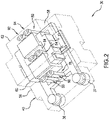
- transformer 30 includes a housing 40 having a base wall 54, a first side wall 56, a second side wall 58 positioned opposite to firsts side wall 56, a third side wall 60, and a fourth side wall 62 positioned opposite of third side wall 60.
- Third side wall 60 extends between and connects first ends (not separately labeled) of first side wall 56 and second side wall 58.
- Fourth side wall 62 extends between and connects second ends (also not separately labeled) of first side wall 56 and second side wall 58.
- a divider wall 64 extends between and connects mid points (not separately labeled) of first side wall 56 and second side wall 58.
- a cover 66 extends over each of first side wall 56, second side wall 58, third side wall 60, and fourth side wall 62.
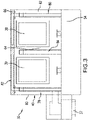
- third side wall 60 supports a first cooling channel 78
- fourth side wall 62 supports a second cooling channel 80
- cover 66 supports a third cooling channel 82
- dividing wall 64 may support a fourth cooling channel 84.
- First cooling channel 78 includes a first coolant path 88 and a second coolant path 90.
- Second cooling channel 80 includes a third coolant path 92 and a fourth coolant path 94.
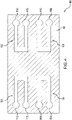
- Third cooling channel 82 includes a first coolant circuit 98, a second coolant circuit 100, a third coolant circuit 101, and a fourth coolant circuit 102. Potting compound may be disposed in the space between various walls and IPT components to allow for enhanced heat conduction from heat generating components to various walls with cooling channels disposed therein.
- first coolant circuit 98 is directly fluidically connected to first coolant path 88 via an inlet 104 and an outlet 106.
- Second cooling circuit 100 is directly fluidically connected to third coolant path 92 via an inlet section 108 and an outlet section 110.
- Third cooling circuit 101 is directly fluidically connected to second coolant path 90 via an inlet 112 and an outlet 113, and fourth coolant circuit 102 is directly fluidically connected to fourth coolant path 94 via an inlet section 115 and an outlet section 116.
- seals (not shown) may be provided on cover 66 or upper portions of third side wall 60 and fourth side wall 62 to ensure that coolant does not leak.
- Cover 120 includes external coolant connections 122.
- first coolant circuit 98 may be coupled to first coolant flow path 88 via an inlet conduit 130 and an outlet conduit 132.
- Second coolant circuit 100 is connected to third coolant flow path 92 via an inlet conduit 136 and an outlet conduit 138.
- Third coolant circuit 101 is connected to second coolant flow path 90 via an inlet conduit 146 and an outlet conduit 148.
- Fourth coolant circuit 102 is connected to fourth coolant flow path 94 via an inlet conduit 150 and an outlet conduit 152.
- Conduits 130, 132, 136, 138, 146, 148, 150, and 152 represent an external flow path and may be joined to housing 40 via quick connects (not separately labeled). The quick disconnects allow cover 120 to be easily removed from housing 40.
- the exemplary embodiments depict a system for removing heat from a transformer including added cooling circuits arranged in a housing cover.
- the cooling system also embeds cooling circuits in the housing itself.
- the incorporation of cooling in the housing cover allows for a greater range of electrical conversion with fewer temperature rise due to heat.
- Incorporating the cooling channels into the housing itself allows for the use of a wider range of cooling options including fluids that could not come into direct contact with electrical generating and conversion portions of the transformer.
Landscapes
- Engineering & Computer Science (AREA)
- Power Engineering (AREA)
- Microelectronics & Electronic Packaging (AREA)
- Physics & Mathematics (AREA)
- Thermal Sciences (AREA)
- Cooling Or The Like Of Electrical Apparatus (AREA)
- Transformer Cooling (AREA)
Abstract
Description
- Exemplary embodiments pertain to the art of transformers and, more particularly, to a conductive cooling system for an interphase transformer.
- Many power systems employ rectifier circuits that convert alternating current power into direct current power having a high voltage such as 270 VDC. In some systems, the rectifier circuit may be paired with a transformer to form a transformer-rectifier unit. In high-current aviation applications, the high current may result in the need to provide one or more transformer-rectifier units connected in parallel. To smooth the output of these parallel connected units, an interphase transformer is often employed. Interphase transformers include layers of overlapping electrically conductive windings that carry electrical current. As the current flows through the windings, heat is produced.
- In high current applications, the interphase transformer produces high levels of heat that may impact energy production. In order to maintain performance, the interphase transformers include cooling systems that are arranged to reduce and/or remove heat from the windings. In most cases, the cooling systems take the form of immersion cooling systems in which a flow of coolant is placed in direct contact with the windings. Given the direct contact, the choice of coolant is limited. Accordingly, the industry would welcome a cooling system for an interphase transformer that allows for increased coolant options.
- Disclosed is a transformer including a housing having a base wall, a first side wall, a second side opposing wall, a third side wall joining the first side wall and the second side wall at a first end including a first cooling channel, and a fourth side wall including joining the first side wall and the second side wall at a second end. The first, second, third, and fourth side walls collectively define an interior portion. A cover extends across each of the first side wall the second side wall, the third side wall, and the fourth side wall. A cooling system includes the first cooling channel disposed in the third side wall, a second cooling channel disposed in the fourth side wall, and a third cooling channel disposed in the cover. The third cooling channel is fluidically connected to at least one of the first cooling channel and the second cooling channel.
- Additionally, or alternatively, in this or other embodiments, the third cooling channel includes a first cooling circuit fluidically connected to the first cooling channel and a second cooling circuit fluidically connected to the second cooling channel.
- Additionally, or alternatively, in this or other embodiments, the first cooling channel includes a first coolant path and a second coolant path and the second coolant channel includes a third coolant path and a fourth coolant path.
- Additionally, or alternatively, in this or other embodiments, the first cooling circuit includes an inlet fluidically connected to the first coolant path and an outlet fluidically connected to the first coolant path.
- Additionally, or alternatively, in this or other embodiments, the second cooling circuit includes an inlet section fluidically connected to the third coolant path and an outlet section fluidically connected to the third coolant path.
- Additionally, or alternatively, in this or other embodiments, the first cooling circuit is directly fluidically connected to the first cooling channel and the second cooling circuit is directly fluidically connected to the second cooling channel.
- Additionally, or alternatively, in this or other embodiments, the first cooling circuit is fluidically connected to the first cooling channel via a first conduit and the second cooling circuit is fluidically connected to the second cooling channel via a second conduit.
- Additionally, or alternatively, in this or other embodiments, the first conduit passes externally of the housing and the second conduit passes externally of the housing.
- Also disclosed is an electrical generation system including a heat exchanger, a pump fluidically connected to the heat exchanger, a generator including a cooling circuit is fluidically connected to the pump, and a transformer is electrically connected to the generator and fluidically connected to the pump. The transformer includes a housing having a base wall, a first side wall, a second side opposing wall, a third side wall joining the first side wall and the second side wall at a first end including a first cooling channel joining the first side wall and the second side wall at a first end, and a fourth side wall including joining the first side wall and the second side wall at a second end. The first, second, third, and fourth side walls collectively define an interior portion. A cover extends across each of the first side wall the second side wall, the third side wall, and the fourth side wall. A cooling system includes a first cooling channel disposed in the third side wall, a second cooling channel disposed in the fourth side wall, and a third cooling channel disposed in the cover. The third cooling channel is fluidically connected to at least one of the first cooling channel and the second cooling channel.
- Additionally, or alternatively, in this or other embodiments, the third cooling channel includes a first cooling circuit fluidically connected to the first cooling channel and a second cooling circuit fluidically connected to the second cooling channel.
- Additionally, or alternatively, in this or other embodiments, the first cooling channel includes a first coolant path and a second coolant path and the second coolant channel includes a third coolant path and a fourth coolant path.
- Additionally, or alternatively, in this or other embodiments, the first cooling circuit includes an inlet fluidically connected to the first coolant path and an outlet fluidically connected to the first coolant path.
- Additionally, or alternatively, in this or other embodiments, the second cooling circuit includes an inlet section fluidically connected to the third coolant path and an outlet section fluidically connected to the third coolant path.
- Additionally, or alternatively, in this or other embodiments, the first cooling circuit is directly fluidically connected to the first cooling channel and the second cooling circuit is directly fluidically connected to the second cooling channel.
- Additionally, or alternatively, in this or other embodiments, the first cooling circuit is fluidically connected to the first cooling channel via a first and the second cooling circuit is fluidically connected to the second cooling channel via a second conduit.
- Additionally, or alternatively, in this or other embodiments, the first conduit passes externally of the housing and the second conduit passes externally of the housing.
- Further disclosed is a method of cooling a transformer having a housing including passing a cooling fluid into a first cooling channel formed in a first side wall of the housing, and flowing the cooling fluid from the first cooling channel into another cooling channel formed in a cover for the housing.
- Additionally, or alternatively, in this or other embodiments, the method further includes passing the cooling fluid into a second cooling channel formed in a second side wall of the housing; and flowing the cooling fluid from the second coolant channel into yet another cooling channel formed in the cover.
- Additionally, or alternatively, in this or other embodiments, flowing the cooling fluid into another cooling channel includes passing the cooling fluid directly from the first cooling channel into the another cooling channel.
- Additionally, or alternatively, in this or other embodiments flowing the cooling fluid into another cooling channel includes passing the cooling fluid from the first cooling channel externally of the housing through a conduit and then into the another cooling channel.
- The following descriptions should not be considered limiting in any way. With reference to the accompanying drawings, like elements are numbered alike:
-
FIG. 1 depicts an electrical generation system including a transformer housing and cooling system, in accordance with an exemplary embodiment; -
FIG. 2 is a partial upper left perspective view of the transformer housing ofFIG. 1 , in accordance with an exemplary embodiment; -
FIG. 3 depicts a plan view of the transformer housing, in accordance with an exemplary aspect; -
FIG. 4 depicts partial cross-sectional bottom view of a cover for the transformer housing, in accordance with an exemplary aspect; -
FIG. 5 depicts a plan view of the transformer housing, in accordance with another aspect of an exemplary embodiment; and -
FIG. 6 depicts a top view of a cover for the transformer housing ofFIG. 5 , in accordance with an exemplary aspect. - A detailed description of one or more embodiments of the disclosed apparatus and method are presented herein by way of exemplification and not limitation with reference to the Figures.
- An electrical generation system, in accordance with an exemplary embodiment, is indicated generally at 10 in
FIG. 1 .Electrical generation system 10 includes anelectrical generation portion 14 and acooling system 16.Cooling system 16 operates to reduce temperatures associated with various components ofelectrical generation portion 14 as will be detailed herein.Cooling system 16 includes aheat exchanger 20 having aninlet 22 and anoutlet 24. A cooling medium, such as air, water, gas or the like, passes throughheat exchanger 20 to absorb heat from a cooling fluid passing frominlet 22 throughoutlet 24.Cooling system 16 also includes apump 26 that operates to circulate the cooling fluid. -
Electrical generation potion 14 includes agenerator 28 and aconverter 29 having atransformer 30. Transformer 30 may take the form of an inter-phase transformer employed in, for example, aircraft applications. In an embodiment,generator 28 includes a statorcooling flow inlet 32, a statorcooling flow outlet 33, a rotor cooling flow,inlet 34 and a rotorcooling flow outlet 35. Transformer 30 includes a convertercooling flow inlet 36 and a convertercooling flow outlet 37. Statorcooling flow outlet 33, rotorcooling flow outlet 35, and convertercooling flow outlet 37 fluidically connected to aninlet 38 ofpump 26. - Referring to
FIGS. 2 and3 ,transformer 30 includes ahousing 40 having abase wall 54, afirst side wall 56, asecond side wall 58 positioned opposite tofirsts side wall 56, athird side wall 60, and afourth side wall 62 positioned opposite ofthird side wall 60.Third side wall 60 extends between and connects first ends (not separately labeled) offirst side wall 56 andsecond side wall 58.Fourth side wall 62 extends between and connects second ends (also not separately labeled) offirst side wall 56 andsecond side wall 58. Adivider wall 64 extends between and connects mid points (not separately labeled) offirst side wall 56 andsecond side wall 58. Acover 66 extends over each offirst side wall 56,second side wall 58,third side wall 60, andfourth side wall 62. - In an embodiment,
third side wall 60 supports afirst cooling channel 78,fourth side wall 62 supports asecond cooling channel 80, cover 66 supports athird cooling channel 82, and dividingwall 64 may support afourth cooling channel 84. First coolingchannel 78 includes afirst coolant path 88 and asecond coolant path 90.Second cooling channel 80 includes athird coolant path 92 and afourth coolant path 94.Third cooling channel 82 includes afirst coolant circuit 98, asecond coolant circuit 100, athird coolant circuit 101, and afourth coolant circuit 102. Potting compound may be disposed in the space between various walls and IPT components to allow for enhanced heat conduction from heat generating components to various walls with cooling channels disposed therein. - In an embodiment,
first coolant circuit 98 is directly fluidically connected tofirst coolant path 88 via aninlet 104 and anoutlet 106.Second cooling circuit 100 is directly fluidically connected tothird coolant path 92 via aninlet section 108 and anoutlet section 110.Third cooling circuit 101 is directly fluidically connected tosecond coolant path 90 via aninlet 112 and anoutlet 113, andfourth coolant circuit 102 is directly fluidically connected tofourth coolant path 94 via aninlet section 115 and anoutlet section 116. At this point, it should be understood that the term "directly fluidically connected" describes a coolant flow path that is entirely internal tohousing 40. In an embodiment, seals (not shown) may be provided oncover 66 or upper portions ofthird side wall 60 andfourth side wall 62 to ensure that coolant does not leak. - In another embodiment depicted in
FIGS. 5 and6 , wherein like reference numbers represent corresponding parts in the respective view, in describing acover 120 in accordance with another exemplary aspect. Cover 120 includesexternal coolant connections 122. For example,first coolant circuit 98 may be coupled to firstcoolant flow path 88 via aninlet conduit 130 and anoutlet conduit 132.Second coolant circuit 100 is connected to thirdcoolant flow path 92 via aninlet conduit 136 and anoutlet conduit 138.Third coolant circuit 101 is connected to secondcoolant flow path 90 via aninlet conduit 146 and anoutlet conduit 148.Fourth coolant circuit 102 is connected to fourthcoolant flow path 94 via aninlet conduit 150 and anoutlet conduit 152.Conduits housing 40 via quick connects (not separately labeled). The quick disconnects allowcover 120 to be easily removed fromhousing 40. - At this point, it should be understood that the exemplary embodiments depict a system for removing heat from a transformer including added cooling circuits arranged in a housing cover. The cooling system also embeds cooling circuits in the housing itself. The incorporation of cooling in the housing cover allows for a greater range of electrical conversion with fewer temperature rise due to heat. Incorporating the cooling channels into the housing itself allows for the use of a wider range of cooling options including fluids that could not come into direct contact with electrical generating and conversion portions of the transformer.
- The terms "about" and "substantially" are intended to include the degree of error associated with measurement of the particular quantity based upon the equipment available at the time of filing the application. For example, "about" and/or "substantially" can include a range of ± 8% or 5%, or 2% of a given value.
- The terminology used herein is for the purpose of describing particular embodiments only and is not intended to be limiting of the present disclosure. As used herein, the singular forms "a", "an" and "the" are intended to include the plural forms as well, unless the context clearly indicates otherwise. It will be further understood that the terms "comprises" and/or "comprising," when used in this specification, specify the presence of stated features, integers, steps, operations, elements, and/or components, but do not preclude the presence or addition of one or more other features, integers, steps, operations, element components, and/or groups thereof.
- While the present disclosure has been described with reference to an exemplary embodiment or embodiments, it will be understood by those skilled in the art that various changes may be made and equivalents may be substituted for elements thereof without departing from the scope of the present disclosure. In addition, many modifications may be made to adapt a particular situation or material to the teachings of the present disclosure without departing from the scope of the claims. Therefore, it is intended that the present disclosure not be limited to the particular embodiment disclosed as the best mode contemplated for carrying out this present disclosure, but that the present disclosure will include all embodiments falling within the scope of the claims.
Claims (13)
- A transformer (30) comprising:a housing (40) having a base wall (54), a first side wall (56), a second side opposing wall (58), a third side wall (60) joining the first side wall and the second side wall at a first end and including a first cooling channel (78), and a fourth side wall (62) joining the first side wall and the second side wall at a second end, the first, second, third, and fourth side walls collectively defining an interior portion;a cover (66; 120) extending across each of the first side wall the second side wall, the third side wall, and the fourth side wall; anda cooling system including the first cooling channel (78) disposed in the third side wall, a second cooling channel (80) disposed in the fourth side wall, and a third cooling channel (82) disposed in the cover, the third cooling channel being fluidically connected to at least one of the first cooling channel and the second cooling channel.
- The transformer according to claim 1, wherein the third cooling channel includes a first cooling circuit (98) fluidically connected to the first cooling channel and a second cooling circuit (100) fluidically connected to the second cooling channel.
- The transformer according to claim 2, wherein the first cooling channel includes a first coolant path (88) and a second coolant path (90) and the second coolant channel includes a third coolant path (92) and a fourth coolant path (94).
- The transformer according to claim 3, wherein the first cooling circuit includes an inlet (104) fluidically connected to the first coolant path and an outlet (106) fluidically connected to the first coolant path.
- The transformer according to claim 3 or 4, wherein the second cooling circuit includes an inlet section (108) fluidically connected to the third coolant path and an outlet section (110) fluidically connected to the third coolant path.
- The transformer according to any of claims 2, 3, 4, or 5, wherein the first cooling circuit is directly fluidically connected to the first cooling channel and the second cooling circuit is directly fluidically connected to the second cooling channel.
- The transformer according to any of claims 2, 3, 4, or 5, wherein the first cooling circuit is fluidically connected to the first cooling channel via a first conduit (130) and the second cooling circuit is fluidically connected to the second cooling channel via a second conduit (136).
- The transformer according to claim 7, wherein the first conduit passes externally of the housing and the second conduit passes externally of the housing.
- An electrical generation system (10) comprising:a heat exchanger (20);a pump (26) fluidically connected to the heat exchanger;a generator (28) including a cooling circuit fluidically connected to the pump; andthe transformer (30) of any preceding claim electrically connected to the generator and fluidically connected to the pump.
- A method of cooling a transformer (30) having a housing (40) comprising:passing a cooling fluid into a first cooling channel (78) formed in a first side wall (56) of the housing; andflowing the cooling fluid from the first cooling channel into another cooling channel formed in a cover (66; 120) for the housing.
- The method of claim 10, further comprising:passing the cooling fluid into a second cooling channel (80) formed in a second side wall (58) of the housing; andflowing the cooling fluid from the second coolant channel into yet another cooling channel formed in the cover.
- The method of claim 10 or 11, wherein flowing the cooling fluid into another cooling channel includes passing the cooling fluid directly from the first cooling channel into the another cooling channel.
- The method of claim 10 or 11, wherein flowing the cooling fluid into another cooling channel includes passing the cooling fluid from the first cooling channel externally of the housing through a conduit (130) and then into the another cooling channel.
Applications Claiming Priority (1)
| Application Number | Priority Date | Filing Date | Title |
|---|---|---|---|
| US17/106,713 US12040118B2 (en) | 2020-11-30 | 2020-11-30 | Cooling system for a transformer and a method of cooling a transformer |
Publications (2)
| Publication Number | Publication Date |
|---|---|
| EP4006925A1 true EP4006925A1 (en) | 2022-06-01 |
| EP4006925B1 EP4006925B1 (en) | 2026-03-18 |
Family
ID=78211994
Family Applications (1)
| Application Number | Title | Priority Date | Filing Date |
|---|---|---|---|
| EP21202730.4A Active EP4006925B1 (en) | 2020-11-30 | 2021-10-14 | Cooling system for a transformer and a method of cooling a transformer |
Country Status (2)
| Country | Link |
|---|---|
| US (1) | US12040118B2 (en) |
| EP (1) | EP4006925B1 (en) |
Citations (5)
| Publication number | Priority date | Publication date | Assignee | Title |
|---|---|---|---|---|
| US9230726B1 (en) * | 2015-02-20 | 2016-01-05 | Crane Electronics, Inc. | Transformer-based power converters with 3D printed microchannel heat sink |
| US10141862B1 (en) * | 2018-03-20 | 2018-11-27 | Ford Global Technologies, Llc | Power supply device |
| EP3499524A1 (en) * | 2017-12-12 | 2019-06-19 | Hamilton Sundstrand Corporation | Systems and methods for cooling toroidal magnetics |
| CN110768522A (en) * | 2019-10-25 | 2020-02-07 | 天津航空机电有限公司 | A liquid-cooled heat dissipation device applied to aviation high-power transformer rectifier |
| EP3648125A1 (en) * | 2018-10-31 | 2020-05-06 | Hamilton Sundstrand Corporation | Thermal management of high power inductors |
Family Cites Families (8)
| Publication number | Priority date | Publication date | Assignee | Title |
|---|---|---|---|---|
| US5014181A (en) | 1989-11-06 | 1991-05-07 | Sundstrand Corporation | Magnetic amplifier package and method of cooling the same |
| US7002443B2 (en) * | 2003-06-25 | 2006-02-21 | Cymer, Inc. | Method and apparatus for cooling magnetic circuit elements |
| US7129808B2 (en) * | 2004-09-01 | 2006-10-31 | Rockwell Automation Technologies, Inc. | Core cooling for electrical components |
| US20100008112A1 (en) | 2008-07-09 | 2010-01-14 | Feng Frank Z | Interphase transformer |
| JP4657329B2 (en) * | 2008-07-29 | 2011-03-23 | 日立オートモティブシステムズ株式会社 | Power converter and electric vehicle |
| JP5855899B2 (en) * | 2011-10-27 | 2016-02-09 | 日立オートモティブシステムズ株式会社 | DC-DC converter and power converter |
| US9943016B2 (en) | 2014-11-04 | 2018-04-10 | Ge Aviation Systems Llc | Cooling structure |
| US9812243B2 (en) | 2015-04-16 | 2017-11-07 | Hamilton Sundstrand Corporation | Power converters with immersion cooling |
-
2020
- 2020-11-30 US US17/106,713 patent/US12040118B2/en active Active
-
2021
- 2021-10-14 EP EP21202730.4A patent/EP4006925B1/en active Active
Patent Citations (5)
| Publication number | Priority date | Publication date | Assignee | Title |
|---|---|---|---|---|
| US9230726B1 (en) * | 2015-02-20 | 2016-01-05 | Crane Electronics, Inc. | Transformer-based power converters with 3D printed microchannel heat sink |
| EP3499524A1 (en) * | 2017-12-12 | 2019-06-19 | Hamilton Sundstrand Corporation | Systems and methods for cooling toroidal magnetics |
| US10141862B1 (en) * | 2018-03-20 | 2018-11-27 | Ford Global Technologies, Llc | Power supply device |
| EP3648125A1 (en) * | 2018-10-31 | 2020-05-06 | Hamilton Sundstrand Corporation | Thermal management of high power inductors |
| CN110768522A (en) * | 2019-10-25 | 2020-02-07 | 天津航空机电有限公司 | A liquid-cooled heat dissipation device applied to aviation high-power transformer rectifier |
Also Published As
| Publication number | Publication date |
|---|---|
| EP4006925B1 (en) | 2026-03-18 |
| US20220172872A1 (en) | 2022-06-02 |
| US12040118B2 (en) | 2024-07-16 |
Similar Documents
| Publication | Publication Date | Title |
|---|---|---|
| US11764652B2 (en) | Polyphased electrical machine with integrated power electronics and an integrated coolant circuit | |
| US9986665B2 (en) | Power conversion apparatus | |
| CN101673980B (en) | Assemblies for electrical machines | |
| TWI669725B (en) | Transformer-based power converters with 3d printed microchannel heat sink | |
| US7049716B2 (en) | Fluid cooled electric machine | |
| US3497737A (en) | Connecting means for dynamoelectric machine cooling system | |
| KR102854127B1 (en) | Liquid/Fluid Cooling Systems for High Power Density (HPD) Transformers | |
| JP2023547912A (en) | System and method for thermal management of electrical machines using refrigerant cans | |
| CA1091741A (en) | Fluidly cooled flat plate neutral bus | |
| US12040118B2 (en) | Cooling system for a transformer and a method of cooling a transformer | |
| EP3488515B1 (en) | Electric motor | |
| US3254246A (en) | Dynamoelectric machines | |
| JP2019047607A (en) | Power converter | |
| AU2014274578B2 (en) | Methods and systems for subsea boosting with direct current and alternating current power systems | |
| US20260058512A1 (en) | Electric Motor | |
| US20240333067A1 (en) | Rotating electric machine system | |
| US12451753B2 (en) | Electric machine with directly cooled windings | |
| US12160161B1 (en) | Immersion-cooled axial flux electric motors and methods of operating thereof | |
| Moguel et al. | An Embedded Microfluidic Approach for Direct Cooling of Copper Windings in Printed Circuit Boards | |
| JP5840583B2 (en) | Electric connector and electric machine equipped with the electric connector | |
| WO2025245058A1 (en) | Oil-cooled power inverters and methods of operating thereof | |
| CN119096457A (en) | Electric Motor | |
| HK1242042A1 (en) | Transformer-based power converters with 3d printed microchannel heat sink |
Legal Events
| Date | Code | Title | Description |
|---|---|---|---|
| PUAI | Public reference made under article 153(3) epc to a published international application that has entered the european phase |
Free format text: ORIGINAL CODE: 0009012 |
|
| STAA | Information on the status of an ep patent application or granted ep patent |
Free format text: STATUS: THE APPLICATION HAS BEEN PUBLISHED |
|
| AK | Designated contracting states |
Kind code of ref document: A1 Designated state(s): AL AT BE BG CH CY CZ DE DK EE ES FI FR GB GR HR HU IE IS IT LI LT LU LV MC MK MT NL NO PL PT RO RS SE SI SK SM TR |
|
| STAA | Information on the status of an ep patent application or granted ep patent |
Free format text: STATUS: REQUEST FOR EXAMINATION WAS MADE |
|
| 17P | Request for examination filed |
Effective date: 20221201 |
|
| RBV | Designated contracting states (corrected) |
Designated state(s): AL AT BE BG CH CY CZ DE DK EE ES FI FR GB GR HR HU IE IS IT LI LT LU LV MC MK MT NL NO PL PT RO RS SE SI SK SM TR |
|
| STAA | Information on the status of an ep patent application or granted ep patent |
Free format text: STATUS: EXAMINATION IS IN PROGRESS |
|
| 17Q | First examination report despatched |
Effective date: 20241212 |
|
| GRAP | Despatch of communication of intention to grant a patent |
Free format text: ORIGINAL CODE: EPIDOSNIGR1 |
|
| STAA | Information on the status of an ep patent application or granted ep patent |
Free format text: STATUS: GRANT OF PATENT IS INTENDED |
|
| INTG | Intention to grant announced |
Effective date: 20251015 |
|
| GRAS | Grant fee paid |
Free format text: ORIGINAL CODE: EPIDOSNIGR3 |
|
| GRAA | (expected) grant |
Free format text: ORIGINAL CODE: 0009210 |
|
| STAA | Information on the status of an ep patent application or granted ep patent |
Free format text: STATUS: THE PATENT HAS BEEN GRANTED |
|
| AK | Designated contracting states |
Kind code of ref document: B1 Designated state(s): AL AT BE BG CH CY CZ DE DK EE ES FI FR GB GR HR HU IE IS IT LI LT LU LV MC MK MT NL NO PL PT RO RS SE SI SK SM TR |
|
| REG | Reference to a national code |
Ref country code: CH Ref legal event code: F10 Free format text: ST27 STATUS EVENT CODE: U-0-0-F10-F00 (AS PROVIDED BY THE NATIONAL OFFICE) Effective date: 20260318 Ref country code: GB Ref legal event code: FG4D |
|
| REG | Reference to a national code |
Ref country code: IE Ref legal event code: FG4D |
|
| REG | Reference to a national code |
Ref country code: DE Ref legal event code: R096 Ref document number: 602021050085 Country of ref document: DE |