EP4006572A1 - Apparatus and method for detecting objects - Google Patents
Apparatus and method for detecting objects Download PDFInfo
- Publication number
- EP4006572A1 EP4006572A1 EP21180365.5A EP21180365A EP4006572A1 EP 4006572 A1 EP4006572 A1 EP 4006572A1 EP 21180365 A EP21180365 A EP 21180365A EP 4006572 A1 EP4006572 A1 EP 4006572A1
- Authority
- EP
- European Patent Office
- Prior art keywords
- velocity vector
- tidal current
- information associated
- target
- detected
- Prior art date
- Legal status (The legal status is an assumption and is not a legal conclusion. Google has not performed a legal analysis and makes no representation as to the accuracy of the status listed.)
- Pending
Links
Images



Classifications
-
- G—PHYSICS
- G01—MEASURING; TESTING
- G01S—RADIO DIRECTION-FINDING; RADIO NAVIGATION; DETERMINING DISTANCE OR VELOCITY BY USE OF RADIO WAVES; LOCATING OR PRESENCE-DETECTING BY USE OF THE REFLECTION OR RERADIATION OF RADIO WAVES; ANALOGOUS ARRANGEMENTS USING OTHER WAVES
- G01S7/00—Details of systems according to groups G01S13/00, G01S15/00, G01S17/00
- G01S7/02—Details of systems according to groups G01S13/00, G01S15/00, G01S17/00 of systems according to group G01S13/00
- G01S7/04—Display arrangements
- G01S7/06—Cathode-ray tube displays or other two dimensional or three-dimensional displays
- G01S7/062—Cathode-ray tube displays or other two dimensional or three-dimensional displays in which different colours are used
-
- G—PHYSICS
- G01—MEASURING; TESTING
- G01S—RADIO DIRECTION-FINDING; RADIO NAVIGATION; DETERMINING DISTANCE OR VELOCITY BY USE OF RADIO WAVES; LOCATING OR PRESENCE-DETECTING BY USE OF THE REFLECTION OR RERADIATION OF RADIO WAVES; ANALOGOUS ARRANGEMENTS USING OTHER WAVES
- G01S13/00—Systems using the reflection or reradiation of radio waves, e.g. radar systems; Analogous systems using reflection or reradiation of waves whose nature or wavelength is irrelevant or unspecified
- G01S13/88—Radar or analogous systems specially adapted for specific applications
- G01S13/91—Radar or analogous systems specially adapted for specific applications for traffic control
- G01S13/917—Radar or analogous systems specially adapted for specific applications for traffic control for marine craft or other waterborne vessels
-
- G—PHYSICS
- G01—MEASURING; TESTING
- G01S—RADIO DIRECTION-FINDING; RADIO NAVIGATION; DETERMINING DISTANCE OR VELOCITY BY USE OF RADIO WAVES; LOCATING OR PRESENCE-DETECTING BY USE OF THE REFLECTION OR RERADIATION OF RADIO WAVES; ANALOGOUS ARRANGEMENTS USING OTHER WAVES
- G01S13/00—Systems using the reflection or reradiation of radio waves, e.g. radar systems; Analogous systems using reflection or reradiation of waves whose nature or wavelength is irrelevant or unspecified
- G01S13/02—Systems using reflection of radio waves, e.g. primary radar systems; Analogous systems
- G01S13/50—Systems of measurement based on relative movement of target
- G01S13/52—Discriminating between fixed and moving objects or between objects moving at different speeds
-
- G—PHYSICS
- G01—MEASURING; TESTING
- G01S—RADIO DIRECTION-FINDING; RADIO NAVIGATION; DETERMINING DISTANCE OR VELOCITY BY USE OF RADIO WAVES; LOCATING OR PRESENCE-DETECTING BY USE OF THE REFLECTION OR RERADIATION OF RADIO WAVES; ANALOGOUS ARRANGEMENTS USING OTHER WAVES
- G01S13/00—Systems using the reflection or reradiation of radio waves, e.g. radar systems; Analogous systems using reflection or reradiation of waves whose nature or wavelength is irrelevant or unspecified
- G01S13/02—Systems using reflection of radio waves, e.g. primary radar systems; Analogous systems
- G01S13/50—Systems of measurement based on relative movement of target
- G01S13/58—Velocity or trajectory determination systems; Sense-of-movement determination systems
- G01S13/581—Velocity or trajectory determination systems; Sense-of-movement determination systems using transmission of interrupted pulse modulated waves and based upon the Doppler effect resulting from movement of targets
- G01S13/582—Velocity or trajectory determination systems; Sense-of-movement determination systems using transmission of interrupted pulse modulated waves and based upon the Doppler effect resulting from movement of targets adapted for simultaneous range and velocity measurements
-
- G—PHYSICS
- G01—MEASURING; TESTING
- G01S—RADIO DIRECTION-FINDING; RADIO NAVIGATION; DETERMINING DISTANCE OR VELOCITY BY USE OF RADIO WAVES; LOCATING OR PRESENCE-DETECTING BY USE OF THE REFLECTION OR RERADIATION OF RADIO WAVES; ANALOGOUS ARRANGEMENTS USING OTHER WAVES
- G01S13/00—Systems using the reflection or reradiation of radio waves, e.g. radar systems; Analogous systems using reflection or reradiation of waves whose nature or wavelength is irrelevant or unspecified
- G01S13/02—Systems using reflection of radio waves, e.g. primary radar systems; Analogous systems
- G01S13/50—Systems of measurement based on relative movement of target
- G01S13/58—Velocity or trajectory determination systems; Sense-of-movement determination systems
- G01S13/583—Velocity or trajectory determination systems; Sense-of-movement determination systems using transmission of continuous unmodulated waves, amplitude-, frequency-, or phase-modulated waves and based upon the Doppler effect resulting from movement of targets
- G01S13/584—Velocity or trajectory determination systems; Sense-of-movement determination systems using transmission of continuous unmodulated waves, amplitude-, frequency-, or phase-modulated waves and based upon the Doppler effect resulting from movement of targets adapted for simultaneous range and velocity measurements
-
- G—PHYSICS
- G01—MEASURING; TESTING
- G01S—RADIO DIRECTION-FINDING; RADIO NAVIGATION; DETERMINING DISTANCE OR VELOCITY BY USE OF RADIO WAVES; LOCATING OR PRESENCE-DETECTING BY USE OF THE REFLECTION OR RERADIATION OF RADIO WAVES; ANALOGOUS ARRANGEMENTS USING OTHER WAVES
- G01S13/00—Systems using the reflection or reradiation of radio waves, e.g. radar systems; Analogous systems using reflection or reradiation of waves whose nature or wavelength is irrelevant or unspecified
- G01S13/02—Systems using reflection of radio waves, e.g. primary radar systems; Analogous systems
- G01S13/50—Systems of measurement based on relative movement of target
- G01S13/58—Velocity or trajectory determination systems; Sense-of-movement determination systems
- G01S13/589—Velocity or trajectory determination systems; Sense-of-movement determination systems measuring the velocity vector
-
- G—PHYSICS
- G01—MEASURING; TESTING
- G01S—RADIO DIRECTION-FINDING; RADIO NAVIGATION; DETERMINING DISTANCE OR VELOCITY BY USE OF RADIO WAVES; LOCATING OR PRESENCE-DETECTING BY USE OF THE REFLECTION OR RERADIATION OF RADIO WAVES; ANALOGOUS ARRANGEMENTS USING OTHER WAVES
- G01S13/00—Systems using the reflection or reradiation of radio waves, e.g. radar systems; Analogous systems using reflection or reradiation of waves whose nature or wavelength is irrelevant or unspecified
- G01S13/66—Radar-tracking systems; Analogous systems
- G01S13/72—Radar-tracking systems; Analogous systems for two-dimensional [2D] tracking, e.g. combination of angle and range tracking, track-while-scan radar
- G01S13/723—Radar-tracking systems; Analogous systems for two-dimensional [2D] tracking, e.g. combination of angle and range tracking, track-while-scan radar by using numerical data
- G01S13/726—Multiple target tracking
-
- G—PHYSICS
- G01—MEASURING; TESTING
- G01S—RADIO DIRECTION-FINDING; RADIO NAVIGATION; DETERMINING DISTANCE OR VELOCITY BY USE OF RADIO WAVES; LOCATING OR PRESENCE-DETECTING BY USE OF THE REFLECTION OR RERADIATION OF RADIO WAVES; ANALOGOUS ARRANGEMENTS USING OTHER WAVES
- G01S13/00—Systems using the reflection or reradiation of radio waves, e.g. radar systems; Analogous systems using reflection or reradiation of waves whose nature or wavelength is irrelevant or unspecified
- G01S13/86—Combinations of radar systems with non-radar systems, e.g. sonar, direction finder
- G01S13/862—Combination of radar systems with sonar systems
-
- G—PHYSICS
- G01—MEASURING; TESTING
- G01S—RADIO DIRECTION-FINDING; RADIO NAVIGATION; DETERMINING DISTANCE OR VELOCITY BY USE OF RADIO WAVES; LOCATING OR PRESENCE-DETECTING BY USE OF THE REFLECTION OR RERADIATION OF RADIO WAVES; ANALOGOUS ARRANGEMENTS USING OTHER WAVES
- G01S13/00—Systems using the reflection or reradiation of radio waves, e.g. radar systems; Analogous systems using reflection or reradiation of waves whose nature or wavelength is irrelevant or unspecified
- G01S13/88—Radar or analogous systems specially adapted for specific applications
- G01S13/89—Radar or analogous systems specially adapted for specific applications for mapping or imaging
-
- G—PHYSICS
- G01—MEASURING; TESTING
- G01S—RADIO DIRECTION-FINDING; RADIO NAVIGATION; DETERMINING DISTANCE OR VELOCITY BY USE OF RADIO WAVES; LOCATING OR PRESENCE-DETECTING BY USE OF THE REFLECTION OR RERADIATION OF RADIO WAVES; ANALOGOUS ARRANGEMENTS USING OTHER WAVES
- G01S13/00—Systems using the reflection or reradiation of radio waves, e.g. radar systems; Analogous systems using reflection or reradiation of waves whose nature or wavelength is irrelevant or unspecified
- G01S13/88—Radar or analogous systems specially adapted for specific applications
- G01S13/93—Radar or analogous systems specially adapted for specific applications for anti-collision purposes
- G01S13/937—Radar or analogous systems specially adapted for specific applications for anti-collision purposes of marine craft
-
- G—PHYSICS
- G01—MEASURING; TESTING
- G01S—RADIO DIRECTION-FINDING; RADIO NAVIGATION; DETERMINING DISTANCE OR VELOCITY BY USE OF RADIO WAVES; LOCATING OR PRESENCE-DETECTING BY USE OF THE REFLECTION OR RERADIATION OF RADIO WAVES; ANALOGOUS ARRANGEMENTS USING OTHER WAVES
- G01S15/00—Systems using the reflection or reradiation of acoustic waves, e.g. sonar systems
- G01S15/02—Systems using the reflection or reradiation of acoustic waves, e.g. sonar systems using reflection of acoustic waves
- G01S15/50—Systems of measurement, based on relative movement of the target
- G01S15/52—Discriminating between fixed and moving objects or between objects moving at different speeds
-
- G—PHYSICS
- G01—MEASURING; TESTING
- G01S—RADIO DIRECTION-FINDING; RADIO NAVIGATION; DETERMINING DISTANCE OR VELOCITY BY USE OF RADIO WAVES; LOCATING OR PRESENCE-DETECTING BY USE OF THE REFLECTION OR RERADIATION OF RADIO WAVES; ANALOGOUS ARRANGEMENTS USING OTHER WAVES
- G01S15/00—Systems using the reflection or reradiation of acoustic waves, e.g. sonar systems
- G01S15/02—Systems using the reflection or reradiation of acoustic waves, e.g. sonar systems using reflection of acoustic waves
- G01S15/50—Systems of measurement, based on relative movement of the target
- G01S15/58—Velocity or trajectory determination systems; Sense-of-movement determination systems
- G01S15/588—Velocity or trajectory determination systems; Sense-of-movement determination systems measuring the velocity vector
-
- G—PHYSICS
- G01—MEASURING; TESTING
- G01S—RADIO DIRECTION-FINDING; RADIO NAVIGATION; DETERMINING DISTANCE OR VELOCITY BY USE OF RADIO WAVES; LOCATING OR PRESENCE-DETECTING BY USE OF THE REFLECTION OR RERADIATION OF RADIO WAVES; ANALOGOUS ARRANGEMENTS USING OTHER WAVES
- G01S15/00—Systems using the reflection or reradiation of acoustic waves, e.g. sonar systems
- G01S15/88—Sonar systems specially adapted for specific applications
- G01S15/96—Sonar systems specially adapted for specific applications for locating fish
-
- G—PHYSICS
- G01—MEASURING; TESTING
- G01S—RADIO DIRECTION-FINDING; RADIO NAVIGATION; DETERMINING DISTANCE OR VELOCITY BY USE OF RADIO WAVES; LOCATING OR PRESENCE-DETECTING BY USE OF THE REFLECTION OR RERADIATION OF RADIO WAVES; ANALOGOUS ARRANGEMENTS USING OTHER WAVES
- G01S7/00—Details of systems according to groups G01S13/00, G01S15/00, G01S17/00
- G01S7/02—Details of systems according to groups G01S13/00, G01S15/00, G01S17/00 of systems according to group G01S13/00
- G01S7/04—Display arrangements
- G01S7/06—Cathode-ray tube displays or other two dimensional or three-dimensional displays
- G01S7/10—Providing two-dimensional [2D] co-ordinated display of distance and direction
- G01S7/12—Plan-position indicators, i.e. P.P.I.
-
- G—PHYSICS
- G01—MEASURING; TESTING
- G01S—RADIO DIRECTION-FINDING; RADIO NAVIGATION; DETERMINING DISTANCE OR VELOCITY BY USE OF RADIO WAVES; LOCATING OR PRESENCE-DETECTING BY USE OF THE REFLECTION OR RERADIATION OF RADIO WAVES; ANALOGOUS ARRANGEMENTS USING OTHER WAVES
- G01S7/00—Details of systems according to groups G01S13/00, G01S15/00, G01S17/00
- G01S7/02—Details of systems according to groups G01S13/00, G01S15/00, G01S17/00 of systems according to group G01S13/00
- G01S7/04—Display arrangements
- G01S7/06—Cathode-ray tube displays or other two dimensional or three-dimensional displays
- G01S7/22—Producing cursor lines and indicia by electronic means
-
- G—PHYSICS
- G01—MEASURING; TESTING
- G01S—RADIO DIRECTION-FINDING; RADIO NAVIGATION; DETERMINING DISTANCE OR VELOCITY BY USE OF RADIO WAVES; LOCATING OR PRESENCE-DETECTING BY USE OF THE REFLECTION OR RERADIATION OF RADIO WAVES; ANALOGOUS ARRANGEMENTS USING OTHER WAVES
- G01S7/00—Details of systems according to groups G01S13/00, G01S15/00, G01S17/00
- G01S7/52—Details of systems according to groups G01S13/00, G01S15/00, G01S17/00 of systems according to group G01S15/00
- G01S7/54—Details of systems according to groups G01S13/00, G01S15/00, G01S17/00 of systems according to group G01S15/00 with receivers spaced apart
-
- G—PHYSICS
- G06—COMPUTING OR CALCULATING; COUNTING
- G06F—ELECTRIC DIGITAL DATA PROCESSING
- G06F18/00—Pattern recognition
- G06F18/20—Analysing
- G06F18/22—Matching criteria, e.g. proximity measures
-
- G—PHYSICS
- G06—COMPUTING OR CALCULATING; COUNTING
- G06V—IMAGE OR VIDEO RECOGNITION OR UNDERSTANDING
- G06V40/00—Recognition of biometric, human-related or animal-related patterns in image or video data
- G06V40/20—Movements or behaviour, e.g. gesture recognition
Definitions
- An example embodiment of the present disclosure generally relates to an object detection apparatus used for detecting one or more objects in a water body.
- marine radars are used for a number of marine activities.
- the marine radars are used in surveillance systems to detect objects such as planes, icebergs, or the like located very far away from the vessel. Further, the marine radar obtains useful information associated with the detected objects such as speed of the object, location of the object, or the like.
- the user has to place an origin mark near an obtained object to determine the positional relationship between the origin mark and the object over a period of time.
- the origin mark moves according to the speed of a tidal current of the water body.
- the object is determined to be a stationary object when the positional relationship is unchanged, and the object is determined to be a moving object when there is a change in the positional relationship.
- the current method for determining the positional relationship is uneconomical, laborious, and time consuming, as inserting the origin mark every time an object is obtained requires more time and additional cost. Further, if the origin mark is not inserted, determining whether the object obtained by a radar is a moving object or a stationery object becomes difficult for the user.
- the prior art document JP2003-114267A relates to a suspicious object detection device.
- the device detects suspicious objects having radio antennas which are dropped on water.
- the device includes a direction finder that detects an object (a ship or a suspicious object) in a search sea area, by transmitting electric waves.
- the device further includes a radar device that searches for the suspicious object in the search sea area.
- the suspicious object is determined by eliminating objects detected by the radar device from objects detected by the direction finder.
- the suspicious object detection device has a limitation in that the device is able to detect the objects on water only when the objects have radio antennas. The device is unable to detect objects that are without any identification hardware.
- an object detection apparatus and method that can automatically and efficiently detect one or more moving objects that are without any identification hardware based on the positional relationship between the at least one object and the tidal current.
- the present invention provides an apparatus for nautical tracking.
- the apparatus for nautical tracking comprising a tracking module, a first vector calculator, a navigation data management module, a second vector calculator, a comparison module and a notification module.
- the tracking module is configured to detect at least one object by a radar and determine radar information associated with the at least one object.
- the first vector calculator is configured to calculate a first velocity vector for the at least one object, based on the radar information associated with the at least one object.
- the navigation data management module is configured to obtain information associated with a tidal current of the water body.
- the second vector calculator is configured to calculate a second velocity vector, based on the information associated with the tidal current.
- the comparison module is configured to compare the first velocity vector and the second velocity vector to classify an object of the at least one object as a target.
- the notification module is configured to notify a user of the target.
- the notification module is further configured to generate one or more display signals on a display, a mark associated with the target that is moving along with the tidal current, based on a similarity between the first velocity vector associated with the target and the second velocity vector.
- the comparison module is further configured to determine a type of the at least one object.
- the type of the at least one object is at least one of a stationary object, an object moving with the tidal current, or an object moving in a direction independent of the tidal current.
- the comparison module is further configured to generate a similarity value between the first velocity vector and the second velocity vector.
- the similarity value is based on at least one of an inner product of the first velocity vector and the second velocity vector and a difference between the first velocity vector and the second velocity vector.
- the information associated with the tidal current comprises at least one of a speed of the tidal current and a direction of the tidal current
- the radar information associated with the at least one object comprises at least one of a speed of the at least one object and a direction in which the at least one object is moving.
- the notification module is further configured to generate one or more display signals associated with the at least one object and change the one or more display signals based on a similarity between the first velocity vector associated with the at least one object and the second velocity vector associated with the tidal current.
- the notification module is further configured to use one or more colors for displaying the target, based on the similarity between the first velocity vector associated with the target and the second velocity vector.
- the notification module is further configured to change the one or more display signals based on a change in distance of the target.
- a method for nautical tracking comprising: detecting at least one object in or adjacent a water body by a radar.
- the method further comprises determining radar information associated with the at least one object; and calculating a first velocity vector for the at least one object, based on the radar information associated with the at least one object.
- the method further comprises obtaining information associated with a tidal current of the water body and calculating a second velocity vector, based on the information associated with the tidal current.
- the method further comprises comparing the first velocity vector and the second velocity vector to classify an object of the at least one object as a target and notifying a user of the target.
- the method further comprises displaying on a display, a mark associated with the target that is moving along with the tidal current, based on a similarity between the first velocity vector associated with the target and the second velocity vector.
- the method further comprises determining a type of the at least one object, and wherein the type of the at least one object is at least one of a stationary object, an object moving in a direction with the tidal current, or an object moving in a direction independent of the tidal current.
- the method further comprises generating a similarity value between the first velocity vector and the second velocity vector.
- the method further comprises determining the similarity value based on at least one of: an inner product of the first velocity vector and the second velocity vector; and a difference between the first velocity vector and the second velocity vector.
- the information associated with the tidal current comprises at least one of a speed of the tidal current and a direction of the tidal current
- the radar information associated with the at least one object comprises at least one of a speed of the at least one object and a direction in which the at least one object is moving.
- the method further comprises generating one or more display signals associated with the at least one object and changing the one or more display signals based on a similarity between the first velocity vector associated with the at least one object and the second velocity vector associated with the tidal current.
- the method further comprises using one or more colors for displaying the target based on the similarity between the first velocity vector and the second velocity vector.
- the method further comprises changing the one or more display signals based on a change in distance of the target.
- a non-transitory computer-readable medium having stored thereon computer-executable instructions which, when executed by a computer, cause the computer to detect at least one object by a radar, determine radar information associated with the at least one object and calculate a first velocity vector for the at least one object, based on the radar information associated with the at least one object.
- the a non-transitory computer-readable medium further cause the computer to obtain information associated with a tidal current of the water body, calculate a second velocity vector, based on the information associated with the tidal current, compare the first velocity vector and the second velocity vector to classify an object of the at least one objects as a target and notify a user of the object.
- a non-transitory computer-readable medium cause the computer to execute the instructions to display on a display, a mark associated with the target that is moving along with the tidal current, based on a similarity between the first velocity vector associated with the target and the second velocity vector.
- an apparatus, a system, and a method for detecting one or more objects in a water body may be provided.
- references in this specification to "one embodiment” or “an embodiment” means that a particular feature, structure, or characteristic described in connection with the embodiment is included in at least one embodiment of the present disclosure.
- the appearance of the phrase “in one embodiment” in various places in the specification are not necessarily all referring to the same embodiment, nor are separate or alternative embodiments mutually exclusive of other embodiments.
- the terms “a” and “an” herein do not denote a limitation of quantity, but rather denote the presence of at least one of the referenced items.
- various features are described which may be exhibited by some embodiments and not by others.
- various requirements are described which may be requirements for some embodiments but not for other embodiments.
- processor capable of processing information in accordance with embodiments of the present invention.
- electronic equipment electronic devices
- devices electronic equipment monitored by the system in accordance with embodiments of the present invention.
- One of the objectives of the present disclosure is to detect one or more objects, e.g., a school of fish in a water body based on an object such as a seabird chasing the one or more schools of fish.
- the present disclosure proposes an object detection system that may be installed on a vessel, where the system detects one or more objects in a water body.
- the one or more objects may be a school of fish in the water body.
- the object detection system detects at least one object by a radar and determines radar information associated with the detected at least one object.
- the object corresponds to the seabird chasing the one or more school of fish.
- the system further determines information associated with tidal current of a water body, and compares the information associated with the tidal current with the information associated with the detected at least one object to determine a type of the detected at least one object.
- the type of the detected at least one object may comprise at least one of: an object moving along the tidal current, a stationary object, and an object moving irrespective of the tidal current.
- the system enables the user (for example, a fisherman) to estimate presence of the one or more school of fish at a larger distance range than a conventional fish finder system whose range is limited to a shorter distance, and thus, increases the efficiency of catching fish.
- the object detection system further indicates the different types of the detected at least one object on a display screen such that the different types of the detected at least one object are visually distinguishable by a user operating the object detection system.
- the different types of the detected at least one object may be indicated on the display screen with different colors or different frames.
- FIG. 1A is a schematic diagram that exemplarily illustrates working environment 100 of an object detection system 101 for detecting one or more objects in a water body, in accordance with an example embodiment.
- the system 101 may be installed at a vessel navigating in the water body.
- the system 101 may comprise a radar that is used to detect at least one object in an atmosphere around the vessel.
- the system 101 may further obtain radar information associated with the detected at least one object.
- the one or more objects in the water body may be one or more school of fish that fishermen want to catch.
- the system 101 may be communicatively coupled with a user device 103, a plurality of sensors 107, and a database 111, via a network 109.
- the user device 103 may comprise an application 103a installed in it, where the application 103a displays different information associated with the detected one or more objects for a user 105 operating the user device 103.
- the user device 103 may be any user accessible device such as a smartphone, a portable computer, a display unit, or the like.
- the user device 103 may comprise a processor, memory, and a communication interface. The processor, the memory and the communication interface may be communicatively coupled to each other.
- the plurality of sensors 107 may be used to determine tidal currents.
- the plurality of sensors 107 may be a current indicator that may determine speed and direction of tidal currents of the water body.
- the plurality of sensors 107 may be an ultrasonic sensor installed in the vessel to transmit ultrasound waves under water, and further configured to receive echoes corresponding to the transmitted ultrasound waves. The plurality of sensors 107 may determine information associated with the tidal currents such as speed and direction of the tidal currents based on the obtained echoes.
- the database 111 may store the latest information about the weather forecast, information about the tidal currents, and nautical charts that may be used by the vessel for navigating in the water body and to determine location of the detected one or more objects.
- the database 111 may further comprise dangerous locations in the water body such as location of a whirlpool or the like.
- the database 111 may comprise navigation data such as information on salinity, water temperature and air temperature, atmospheric pressure, and wind (speed, gusts, and direction), geographical location (in terms of longitude and latitude) of the vessel, or the like.
- the network 109 may comprise suitable logic, circuitry, and interfaces that may be configured to provide a plurality of network ports and a plurality of communication channels for transmission and reception of data, such as the information associated with the tidal current, radar information associated with detected object, or the like.
- Each network port may correspond to a virtual address (or a physical machine address) for transmission and reception of the communication data.
- the virtual address may be an Internet Protocol Version 4 (IPv4) or an IPv6 address and the physical address may be a Media Access Control (MAC) address.
- IPv4 Internet Protocol Version 4
- MAC Media Access Control
- the network 109 may be associated with an application layer for implementation of communication protocols based on one or more communication requests from at least one of the one or more communication devices.
- the communication data may be transmitted or received, via the communication protocols.
- wired and wireless communication protocols may include, but are not limited to, Transmission Control Protocol and Internet Protocol (TCP/IP), User Datagram Protocol (UDP), Hypertext Transfer Protocol (HTTP), File Transfer Protocol (FTP), ZigBee, EDGE, infrared (IR), IEEE 802.11, 802.16, cellular communication protocols, and/or BLUETOOTH (BT) communication protocols.
- TCP/IP Transmission Control Protocol and Internet Protocol
- UDP User Datagram Protocol
- HTTP Hypertext Transfer Protocol
- FTP File Transfer Protocol
- ZigBee ZigBee
- EDGE infrared
- IEEE 802.11, 802.16, cellular communication protocols and/or BLUETOOTH (BT) communication protocols.
- BT BLUETOOTH
- Examples of the network 109 may include, but is not limited to a wireless channel, a wired channel, and a combination of wireless and wired channel.
- the wireless or wired channel may be associated with a network standard which may be defined by one of a Local Area Network (LAN), a Personal Area Network (PAN), a Wireless Local Area Network (WLAN), a Wireless Sensor Network (WSN), Wireless Area Network (WAN), Wireless Wide Area Network (WWAN), a Long Term Evolution (LTE) network, a plain old telephone service (POTS), and a Metropolitan Area Network (MAN).
- the wired channel may be selected on the basis of bandwidth criteria. For example, an optical fiber channel may be used for a high bandwidth communication. Further, a coaxial cable-based or Ethernet-based communication channel may be used for moderate bandwidth communication.
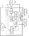
- FIG. 1B illustrates a block diagram of the system 101, exemplarily illustrated in FIG. 1A , for detecting the one or more objects, in accordance with an example embodiment of the present disclosure.
- the system 101 may include processing circuitry 115 configured to execute stored instructions, as well as memory 113 that stores instructions that are executable by the processing circuitry 115.
- the memory 113 can include random access memory (RAM), read only memory (ROM), flash memory, or any other suitable memory systems.
- the processing circuitry 115 may be connected through a bus 117 to the memory 113.
- the processing circuitry 115 includes a tracking module 119, a comparison module 121, and a navigation data management module 123. Further, different components of the processing circuitry 115 are connected to the user device 103, the plurality of sensors 107, and the database 111, via the network 109.
- the tracking module 119 is configured to detect the at least one object.
- the tracking module 119 may comprise a transceiver that is used to transmit and receive radio signals. The reflected signal, i.e. echoes, corresponding to the transmitted radio signals, from the detected at least one object, will be received by the transceiver. The tracking module 119 may then determine radar information associated with the detected at least one object based on the echoes.
- the radar information may comprise a speed of the detected at least one object, a location of the detected at least one object, and a direction in which the detected at least one object is traveling.
- the radar information determination part 119 outputs radar information to a first vector calculator 125.
- the first vector calculator 125 calculates a first velocity vector associated with the detected at least one object based on the radar information.
- the tracking module 119 may be a radar device transmitting radar signals to detect the at least one target in the atmosphere around the vessel.
- the processing circuitry 115 is further configured to use the plurality of sensors 107 configured to determine the speed and direction of the tidal current.
- the plurality of sensors 107 may correspond to a tidal current indicator installed in a vessel to determine information associated with the tidal current.
- the plurality of sensors 107 may correspond to an acoustic Doppler current profiler (ADCP) installed in the vessel to determine information associated with the tidal current.
- ADCP acoustic Doppler current profiler
- the plurality of sensors 107 use the working principle of the Doppler Effect to measure the vertical distribution of speed of the water as well as the direction of the current.
- the ultrasound waves may be transmitted at a constant frequency through the water body.
- Echoes corresponding to the transmitted ultrasound waves, reflected from the particles suspended in the moving water may be received by the plurality of sensors 107. Since the particles move at the same speed as the water that carries them, the echoes received from the particles may be used to determine information associated with the tidal current of the water body.
- the plurality of sensors 107 may comprise four acoustic transducers that transmit the ultrasound waves or acoustic pulses and receive reflected acoustic pulses from four different directions.
- the plurality of sensors 107 may be referred as the tidal current indicator.
- the tidal current indicator determines the current direction based on the received acoustic pulses.
- the tidal current indicator may convert the current direction to earth coordinates, by using trigonometric relationships.
- the transmitted acoustic pulses extend from the vessel down to the bottom of the water body, the tidal current indicator can measure the tidal current at different depths simultaneously. As a consequence, the velocity and current direction can be determined from the surface to the bottom of the water body.
- the tidal current indicator may be configured to use a low ultrasonic frequency to measure the speed of the vessel relative to the bottom of the water body. The speed of the vessel may be subtracted from the determined tidal current to obtain more accurate measurements of the information associated with the tidal current such as velocities of the tidal current.
- the information associated with the tidal current may also comprise the direction of the tidal current.
- the tidal current indicator provides the information associated with the tidal current to the navigation data management module 123 of the processing circuitry 115.
- the navigation data management module 123 obtains information associated with the tidal current.
- the navigation data management module 123 further obtains weather data from the database 111 and may use the weather data in real time to accurately determine or update the information associated with the tidal current, e.g. the speed and the direction of the tidal current.
- the navigation data management module 123 may obtain the information associated with the tidal current directly from the database 111. However, it is possible that the information obtained from the database 111 may not be as accurate as the information obtained from the plurality of sensors 107 (or the tidal current indicator). Further, the navigation data management module 123 output these information to a second vector calculator 126.
- the second vector calculator 126 calculates a second velocity vector based on the information associated with the tidal current.
- Second velocity vector 10 , N , 2 6 , N , 3 where the first row represents a first tidal current flowing at the speed of 10 km/hr toward the north direction at a depth of 2 km. Similarly, the second row represents a second tidal current flowing at the speed of 6 km/hr flowing toward the north direction at a depth of 3 km.
- the navigation data management module 123 determines navigation data and provides it to the user device 103.
- the navigation data may be used by the user device 103 to prepare a map and indicate different types of the detected at least one target at their corresponding positions in the map.
- the navigation data may comprise nautical charts that provide basic navigation information such as depth of the water body and dangerous locations such as whirlpool or the like in the water body.
- the navigation data may further comprise information on salinity, water and air temperature, atmospheric pressure, and wind (speed, gusts, and direction), geographical location (in terms of longitude and latitude) of the vessel, or the like.
- the processing circuitry 115 is further configured to use the comparison module 121 to determine the type of the detected at least one object.
- the comparison module 121 is configured to compare the speed and the direction of the detected at least one object with the speed and the direction of the tidal current. Based on the comparison, the comparison module 121 may determine whether the detected at least one object is moving in the same direction and with the same speed of the tidal current or not. Further, the comparison module 121 may also determine whether the detected at least one object is stationary with respect to the tidal current or moving in a direction independent of the tidal current.
- the comparison module 121 obtains the first velocity vector associated with the detected at least one object, and the second velocity vector associated with the tidal current of the water body.
- the processing circuitry 115 is further configured to use the comparison module 121 to compare the first velocity vector and the second velocity vector and generate a similarity value between the first velocity vector and the second velocity vector.
- the comparison module 121 is further configured to determine the type of the detected at least one object based on the similarity value between the first velocity vector and the second velocity vector.
- the similarity value between the first velocity vector and the second velocity vector is determined by calculating the inner product of the first velocity vector and the second velocity vector as described in equation (3) above.
- the similarity may be determined by calculating the difference between the speed and direction of the first velocity vector and the second velocity vector.
- a speed threshold value and a direction threshold value may be predetermined or dynamically configured based on the tidal currents.
- the detected at least one object corresponding to the first velocity vector is determined to be moving with the same speed as that of the velocity of the tidal current.
- the detected at least one object corresponding to the first velocity vector is determined to be moving with a speed different from that of the velocity of the tidal current.
- the detected at least one object is determined to be moving in the same direction as that of the tidal current.
- a threshold degree for example, in the azimuth plane
- the detected at least one object is determined to be moving in a direction different than that of the tidal current.
- the one or more objects such as a school of fish are determined to be present at the location of the detected at least one object (for example, at the location where the group of seabirds are flying or chasing the school of fish).
- the comparison module 121 provides the result of the comparison to the notification module 127.
- a notification module 127 generates a display signal based on the comparison result and out put it to a user device 103.
- the notification module 127 may be included in the user device 103.
- the user device 103 is used to provide visual information associated with the detected at least one object and/or tidal current, where the information may be location of the detected at least one object, type of the detected at least one object, speed of the detected at least one object, speed and direction of the tidal current, or the like.
- the user device 103 may comprise a liquid crystal display (LCD) screen, light emitting diode (LED) screen, cathode ray tube (CRT) screen, or the like to display the visual information.
- LCD liquid crystal display
- LED light emitting diode
- CRT cathode ray tube
- the user device 103 comprises the application 103a installed in it, where the application 103a may be used by the user device 103 to generate one or more display signals associated with the detected at least one object, and to change the one or more display signals based on the similarity value between the first velocity vector and the second velocity vector.
- the user device 103 may change the one or more display signals based on the similarity vector.
- Changing the one or more display signal may correspond to changing a color of the detected at least one object based on the similarity vector.
- Using the one or more display signals for different types of the detected at least one object enables the user 105 to distinguish between different types of the detected at least one object such as stationary objects or moving objects.
- the notification module 127 is configured to use one or more colors for displaying the detected at least one object, based on the similarity between the first velocity vector associated with the detected at least one object and the second velocity vector. In an example embodiment, the notification module 127 is further configured to generate display signal of the detected at least one object on the display screen based on change in distance of the detected at least one object.
- the system 101 may be comprised of an apparatus, where the apparatus for detecting one or more objects in water body may comprise processing circuitry configured to detect at least one object, wherein the at least one object is different from the one or more objects in the water body.
- the processing circuitry obtains radar information associated with the detected at least one object.
- the processing circuitry is further configured to calculate a first velocity vector based on the radar information associated with the detected at least one object.
- the processing circuitry is configured to determine information associated with a tidal current of the water body, calculate a second velocity vector based on the information associated with the tidal current, compare the first velocity vector and the second velocity vector to detect the one or more objects, and further, notify a user 105, based on the detected one or more objects.
- FIG. 2 is a schematic that illustrates a display screen of the user device 103, in accordance with an example embodiment.
- the display screen illustrated here is exemplary and is used in order to better understand the present disclosure.
- the display screen should not be considered limiting the scope of the disclosure.
- the display screen comprises concentric range rings 201a, 201b, and 201c, a range scale field 203, a heading line 205, stationary objects 207a, 207b, 207c, and 207d, objects 209a, 209b, 209c, and 209d moving with the same speed and in the same direction as that of the tidal current, and objects 211a, 211b, and 211c moving in a direction independent of the tidal current, i.e., the objects 211a, 211b, and 211c are moving in a direction different from the tidal current.
- appropriate range scale field may be selected. In the FIG.
- the system 101 detects the one or more objects in the range scale of 6 miles which is indicated in the range scale field 203, and each fixed concentric range ring 201a-201c is predetermined at an interval of 2 miles.
- the outer concentric range ring 201c further represents azimuthal angles in degrees.
- the concentric range rings 201a-201c provide the location of the detected objects with respect to a vessel, comprising the system 101, which is assumed at the center of the display screen.
- the display screen uses the heading line 205, where the heading line 205 extends from the center to the outer edge and the heading line 205 marks the dead ahead direction of the vessel at the moment.
- the heading line 205 may point in the direction in which the vessel is headed and may rotate on the screen as the vessel turns to a new course.
- the heading line 205 is temporarily hidden to look for weak objects dead ahead.
- the display screen further indicates detected objects along with their locations. Further, based on the similarity between the first velocity vector and the second velocity vector, the different types of the detected at least one object is indicated on the screen such that the different types of the detected objects can be visually distinguished by the user 105.
- the user device 103 may represent different types of the objects using different colors or different frames around the detected different types of the objects.
- the screen displays the detected stationary objects 207a-207d with a square frame around the objects 207a-207d.
- the user 105 can easily distinguish the stationary objects 207a-207d by looking at the screen. Further, the user 105 can determine location of the stationary objects 207a-207d. For example, the stationary object 207a is located at approximately 2.2 miles from the vessel. Further, the objects 209a-209d that are moving with the same speed and in the same direction as that of the tidal current are indicated on the screen without any frame around them.
- the objects 211a-211c moving in the direction independent of the tidal current are indicated on the screen with a circular frame around the objects 211a-211c.
- the different types of the objects may be displayed on the display screen with different colors.
- the processing circuitry 115 is configured to display on the display, a mark associated with the at least one object moving along with the tidal current, that is determined to have the same speed and direction as that of the tidal current (i.e. drifting objects).
- the mark enables the user 105 to distinguish drifting objects from the stationary object.
- the mark may be changed based on the similarity value between the first velocity vector associated with the detected objects that are flowing along with the tidal current and the second velocity vector.
- the processing circuitry 115 is configured to display a cursor (not shown in Figure) on the display screen of the user device 103 such that the user 105 is able to move the cursor to different points in the nautical chart. Further, the processing circuitry 115 is configured to display the distance and the azimuth between the object and the cursor when the object has the same speed and direction of the tidal current.
- FIG. 3 illustrates a scenario 300 where a vessel 301 uses the system 101 for detecting the one or more schools of fish 305a, 305b in a water body 303, in accordance with an example embodiment.
- the vessel 301 in the water body 303 comprises the object detecting system 101 for detecting the one or more objects 305a, 305b or the like.
- One of the objectives of the present disclosure is to detect one or more school of fish such as 305a, 305b based on the detection of the seabird flying with the speed and in the direction of the tidal current of the water body 303.
- the object detection system 101 transmits radar signals 309 (or electromagnetic waves or radio waves above the surface of the water body 303) in a predetermined range.
- the radar signals 309 When the radar signals 309 come into contact with the at least one object 307 they are reflected or scattered in many directions.
- the radar signals that are reflected back (i.e. echoes) 311 towards the system 101 are the desirable ones.
- the echoes 311 are used by the system 101 to determine radar information associated with the detected at least one object 307.
- the radar information associated with the detected at least one object 307 may comprise location information of the at least one object 307, speed of the at least one object 307, direction in which the at least one object 307 is moving, or the like.
- the system 101 may transmit the radar signals 309 in a 360-degree circle above the surface of the water body 303.
- the system 101 detects bearing and range of echoing pulse that returns from significant surrounding objects to produce a map like display on a display unit (not shown in FIG. 3 ), where the map may display position (latitude and longitude) of the detected at least one object 307, speed and the direction of the detected at least one object 307, or the like.
- the detected at least one object 307 is moving with a speed that is the same as the speed of the tidal current and further, moving in a direction that is the same as that of the tidal current. Because when the detected at least one object is moving in the direction with the tidal current, it may be determined that the detected at least one object 307 is one or more seabirds chasing one or more school of fish 305a, 305b. Further, based on the speed and direction of the detected at least one object 307, a type of the detected at least one object 307 may be determined.
- the system 101 may obtain speed and direction of the tidal current and compare the speed and the direction of the detected at least one object 307 with the speed and the direction of the tidal current. Further, the system 101 categorizes the detected at least one object 307 into different types based on the speed and direction of the detected at least one object 307 and the speed and the direction of the tidal current. In an example embodiment, system 101 may obtain information associated with the tidal current directly from the database 111. In another embodiment, the vessel 301 may use the plurality of sensors 107 to determine the tidal current.
- the vessel 301 may transmit 'pings' of sound (or ultrasound waves) 313 at a constant frequency through the water body 303.
- the vessel 301 may use the tidal current indicator to transmit the ultrasound waves.
- the sound waves 313 travel, they bounce off particles suspended in the moving water, and reflect back as echoes 315 towards the plurality of sensors 107. Due to Doppler Effect, the frequency of the reflected wave 315 will be high or low depending on the particles moving either towards the vessel 301 or away from the vessel 301.
- the sound wave reflected by particles moving away from the instrument will have a lower frequency return and vice versa.
- the difference in frequency between the transmitted waves 313 and the frequency of the returning waves or echoes 315 is called the Doppler shift. Since the particles move at the same speed as the water that carries them, the Doppler shift is proportional to the speed of the water or current i.e. tidal current.
- the type of the detected at least one object 307 is at least one of: a stationary object, an object moving with the same speed and in the same direction as that of the tidal current, or an object moving in a direction independent of the tidal current.
- the at least one object may comprise at least one seabird (as illustrated in the FIG. 3 ), where the seabird may be moving with the same speed and in the same direction as that of the tidal current. Therefore, the system 101 may determine that the seabird is chasing the schools of fish 305a, 305b or there is driftage on the sea surface.
- the system 101 may detect stationary objects such as a lighthouse, or other objects which are not moving with the tidal current such as helicopters, planes, or other birds which are not chasing after the school of fish. In this way, based on the detected at least one object 307, the system 101 detects the one or more driftages or schools of fish such as 305a, 305b.
- At least one target may be a subset of the at least one objects that is of interest to the user and therefore the apparatus notifies the user of the at least one object classified as a target.
- the user may be interested in different subsets of objects and therefore may be notified of different subsets which are classified as targets.
- the at least one target is at least one type of object which may be differentiated from other types of objects.
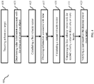
- FIG. 4 is a flowchart that illustrates steps of a method 400 executed by the system 101 for nautical tracking, in accordance with an example embodiment.
- the method 400 starts at step 401, where at least one object may be detected in or adjacent a water body.
- radio waves of high frequencies may be transmitted in air by a radar.
- the radio waves are reflected (i.e. echoes) by the at least one object.
- echoes received from the at least one object may be used to determine radar information associated with the at least one object.
- the radar information associated with the at least one object may comprise speeds and directions of the at least one object.
- a first velocity vector associated with the detected at least one object may be calculated based on the radar information associated with the at least one object.
- the first velocity vector may comprise speed of the detected at least one object, distance at which the at least one object is detected, direction in which the detected at least one object is moving, or the like.
- information associated with the tidal current may be obtained.
- the information associated with the tidal current may be obtained from the database 111.
- the information associated with the tidal current may be obtained from the plurality of sensors 107 installed in the vessel.
- the information associated with a tidal current may comprise the speed and direction of the tidal current.
- a second velocity vector may be calculated based on the information associated with a tidal current of the water body.
- the second velocity vector may be determined by the navigation data management module 123.
- the second velocity vector may comprise the direction in which the tidal current in flowing, speed of the tidal current, depth at which the speed of the tidal current is determined, or the like.
- the speed and direction associated with the at least one object may be compared with the speed and direction of the tidal current in order to classify an object of the at least one objects as a target.
- an object in the water body not detected by the radar may be inferred to be present and classified as a target by the same process.
- the first velocity vector may be compared with the second velocity vector.
- the different types of detected at least one object may be at least one of stationary objects, objects moving with the same speed and in the same direction as that of the tidal current, or objects moving in a direction independent of the tidal current.
- a location of an object in the water body such as a school of fish may be determined. This is because the at least one object moving with the same speed and in the same direction as that of the tidal current is determined to be one or more seabirds chasing the school of fish or be one or more driftage. Therefore, the school of fish is determined to be present in the water body at the location where the one or more seabirds are detected.
- the user 105 may be notified about the one or more objects detected or classified at step 411 as a target on a display screen of the user device 103.
- the notification may comprise the location of the detected one or more objects.
- different types of the detected at least one object may be displayed on the display screen of the user device 103.
- the screen may display different types of the detected at least one object with different colors or frames in order to enable the user 105 to easily distinguish between different types of the detected at least one object.
- Example embodiments of the present disclosure may thus provide for the system 101 and the apparatus that detects the one or more objects such as a school of fish in the water body based on the determination that the detected at least one object such as a group of seabirds are chasing the one or more objects (i.e. the school of fish).
- the apparatus determines whether the detected at least one object is a stationary object, an object moving with the same speed and in the same direction as that of the tidal current, or the objects moving in a direction independent of the tidal current.
- the detected at least one object may be determined to be chasing the school of fish.
- the apparatus first calculates the first velocity vector for the detected at least one object based on radar information associated with the detected at least one object.
- the apparatus further calculates the second velocity vector based on information associated with the tidal current.
- the apparatus compares the first velocity vector and the second velocity vector in order to determine similarity between the two vectors. Based on the similarity the apparatus determines different types of the detected at least one object.
- the apparatus further displays different types of the detected at least one object with different colors or frames in order to enable the user 105 to visually distinguish between different types of the objects.
- the apparatus determines the location of the one or more object (the school of fish).
- the objects moving in the direction with the tidal current are determined to be one or more seabirds chasing the school of fish or one or more driftages. Therefore, the one or more school of fish are determined to be present in the water body at the location of the detected at least one object moving along with the tidal current.
Landscapes
- Engineering & Computer Science (AREA)
- Remote Sensing (AREA)
- Radar, Positioning & Navigation (AREA)
- Physics & Mathematics (AREA)
- General Physics & Mathematics (AREA)
- Computer Networks & Wireless Communication (AREA)
- Theoretical Computer Science (AREA)
- Electromagnetism (AREA)
- Acoustics & Sound (AREA)
- Computer Vision & Pattern Recognition (AREA)
- Data Mining & Analysis (AREA)
- Psychiatry (AREA)
- Human Computer Interaction (AREA)
- Bioinformatics & Computational Biology (AREA)
- Bioinformatics & Cheminformatics (AREA)
- Artificial Intelligence (AREA)
- Health & Medical Sciences (AREA)
- Evolutionary Biology (AREA)
- General Health & Medical Sciences (AREA)
- Social Psychology (AREA)
- General Engineering & Computer Science (AREA)
- Multimedia (AREA)
- Life Sciences & Earth Sciences (AREA)
- Evolutionary Computation (AREA)
- Ocean & Marine Engineering (AREA)
- Radar Systems Or Details Thereof (AREA)
- Measurement Of Velocity Or Position Using Acoustic Or Ultrasonic Waves (AREA)
Abstract
Description
- An example embodiment of the present disclosure generally relates to an object detection apparatus used for detecting one or more objects in a water body.
- With advancements in the field of marine radar technology, nowadays marine radars are used for a number of marine activities. For example, the marine radars are used in surveillance systems to detect objects such as planes, icebergs, or the like located very far away from the vessel. Further, the marine radar obtains useful information associated with the detected objects such as speed of the object, location of the object, or the like. Conventionally, the user has to place an origin mark near an obtained object to determine the positional relationship between the origin mark and the object over a period of time. The origin mark moves according to the speed of a tidal current of the water body. The object is determined to be a stationary object when the positional relationship is unchanged, and the object is determined to be a moving object when there is a change in the positional relationship. However, the current method for determining the positional relationship is uneconomical, laborious, and time consuming, as inserting the origin mark every time an object is obtained requires more time and additional cost. Further, if the origin mark is not inserted, determining whether the object obtained by a radar is a moving object or a stationery object becomes difficult for the user.
- The prior art document
JP2003-114267A - Accordingly, there is a need of an object detection apparatus and method that can automatically and efficiently detect one or more moving objects that are without any identification hardware based on the positional relationship between the at least one object and the tidal current.
- In order to solve the foregoing problem, the present invention provides an apparatus for nautical tracking. The apparatus for nautical tracking, the apparatus comprising a tracking module, a first vector calculator, a navigation data management module, a second vector calculator, a comparison module and a notification module. The tracking module is configured to detect at least one object by a radar and determine radar information associated with the at least one object. The first vector calculator is configured to calculate a first velocity vector for the at least one object, based on the radar information associated with the at least one object. The navigation data management module is configured to obtain information associated with a tidal current of the water body. The second vector calculator is configured to calculate a second velocity vector, based on the information associated with the tidal current. The comparison module is configured to compare the first velocity vector and the second velocity vector to classify an object of the at least one object as a target. The notification module is configured to notify a user of the target.
- According to some example embodiment, in order to notify the user, the notification module is further configured to generate one or more display signals on a display, a mark associated with the target that is moving along with the tidal current, based on a similarity between the first velocity vector associated with the target and the second velocity vector.
- According to some example embodiment, the comparison module is further configured to determine a type of the at least one object. The type of the at least one object is at least one of a stationary object, an object moving with the tidal current, or an object moving in a direction independent of the tidal current.
- According to some example embodiment, in order to classify the target, the comparison module is further configured to generate a similarity value between the first velocity vector and the second velocity vector.
- According to some example embodiment, the similarity value is based on at least one of an inner product of the first velocity vector and the second velocity vector and a difference between the first velocity vector and the second velocity vector.
- According to some example embodiment, the information associated with the tidal current comprises at least one of a speed of the tidal current and a direction of the tidal current, and wherein the radar information associated with the at least one object comprises at least one of a speed of the at least one object and a direction in which the at least one object is moving.
- According to some example embodiment, to display the target, the notification module is further configured to generate one or more display signals associated with the at least one object and change the one or more display signals based on a similarity between the first velocity vector associated with the at least one object and the second velocity vector associated with the tidal current.
- According to some example embodiment, the notification module is further configured to use one or more colors for displaying the target, based on the similarity between the first velocity vector associated with the target and the second velocity vector.
- According to some example embodiment, the notification module is further configured to change the one or more display signals based on a change in distance of the target.
- According to an example embodiment, a method is provided for nautical tracking, the method comprising: detecting at least one object in or adjacent a water body by a radar. The method further comprises determining radar information associated with the at least one object; and calculating a first velocity vector for the at least one object, based on the radar information associated with the at least one object. The method further comprises obtaining information associated with a tidal current of the water body and calculating a second velocity vector, based on the information associated with the tidal current. The method further comprises comparing the first velocity vector and the second velocity vector to classify an object of the at least one object as a target and notifying a user of the target.
- According to an example embodiment, for notifying the user, the method further comprises displaying on a display, a mark associated with the target that is moving along with the tidal current, based on a similarity between the first velocity vector associated with the target and the second velocity vector.
- According to an example embodiment, the method further comprises determining a type of the at least one object, and wherein the type of the at least one object is at least one of a stationary object, an object moving in a direction with the tidal current, or an object moving in a direction independent of the tidal current.
- According to an example embodiment, for classifying the target, the method further comprises generating a similarity value between the first velocity vector and the second velocity vector.
- According to some example embodiment, the method further comprises determining the similarity value based on at least one of: an inner product of the first velocity vector and the second velocity vector; and a difference between the first velocity vector and the second velocity vector.
- According to an example embodiment, the information associated with the tidal current comprises at least one of a speed of the tidal current and a direction of the tidal current, and the radar information associated with the at least one object comprises at least one of a speed of the at least one object and a direction in which the at least one object is moving.
- According to an example embodiment, where for displaying the target, the method further comprises generating one or more display signals associated with the at least one object and changing the one or more display signals based on a similarity between the first velocity vector associated with the at least one object and the second velocity vector associated with the tidal current.
- According to an example embodiment, the method further comprises using one or more colors for displaying the target based on the similarity between the first velocity vector and the second velocity vector.
- According to an example embodiment, the method further comprises changing the one or more display signals based on a change in distance of the target.
- According to an example embodiment, a non-transitory computer-readable medium having stored thereon computer-executable instructions which, when executed by a computer, cause the computer to detect at least one object by a radar, determine radar information associated with the at least one object and calculate a first velocity vector for the at least one object, based on the radar information associated with the at least one object. The a non-transitory computer-readable medium further cause the computer to obtain information associated with a tidal current of the water body, calculate a second velocity vector, based on the information associated with the tidal current, compare the first velocity vector and the second velocity vector to classify an object of the at least one objects as a target and notify a user of the object.
- According to an example embodiment, in order to notify the user, a non-transitory computer-readable medium cause the computer to execute the instructions to display on a display, a mark associated with the target that is moving along with the tidal current, based on a similarity between the first velocity vector associated with the target and the second velocity vector.
- The foregoing summary is illustrative only and is not intended to be in any way limiting. In addition to the illustrative aspects, embodiments, and features described above, further aspects, embodiments, and features will become apparent by reference to the drawings and the following detailed description.
- According to this disclosure, an apparatus, a system, and a method for detecting one or more objects in a water body may be provided.
- The present disclosure is illustrated by way of example and not by way of limitation in the figures of the accompanying drawings, in which like reference numerals indicate like elements and in which:
-
FIG. 1A is a schematic diagram that exemplarily illustrates a working environment of an object detection system for detecting one or more objects in a water body, in accordance with an example embodiment; -
FIG. 1B illustrates a block diagram of the system, exemplarily illustrated inFIG. 1A , for detecting the one or more objects, in accordance with an example embodiment of the present disclosure; -
FIG. 2 is a schematic that illustrates a display screen of the display unit, in accordance with an example embodiment; -
FIG. 3 illustrates an exemplary scenario where a vessel uses the system for detecting one or more schools of fish in a water body, in accordance with an example embodiment; and -
FIG. 4 is a flowchart that illustrates steps of a method executed by the apparatus for detecting the one or more objects in the water body, in accordance with an example embodiment. - In the following description, for purposes of explanation, numerous specific details are set forth in order to provide a thorough understanding of the present disclosure. It will be apparent, however, to one skilled in the art that the present disclosure may be practiced without these specific details. In other instances, systems and methods are shown in block diagram form only in order to avoid obscuring the present disclosure.
- Reference in this specification to "one embodiment" or "an embodiment" means that a particular feature, structure, or characteristic described in connection with the embodiment is included in at least one embodiment of the present disclosure. The appearance of the phrase "in one embodiment" in various places in the specification are not necessarily all referring to the same embodiment, nor are separate or alternative embodiments mutually exclusive of other embodiments. Further, the terms "a" and "an" herein do not denote a limitation of quantity, but rather denote the presence of at least one of the referenced items. Moreover, various features are described which may be exhibited by some embodiments and not by others. Similarly, various requirements are described which may be requirements for some embodiments but not for other embodiments.
- Some embodiments of the present disclosure will now be described more fully hereinafter with reference to the accompanying drawings, in which some, but not all, embodiments of the disclosure are shown. Indeed, various embodiments of the disclosure may be embodied in many different forms and should not be construed as limited to the embodiments set forth herein; rather, these embodiments are provided so that this disclosure will satisfy applicable legal requirements. Like reference numerals refer to like elements throughout. As used herein, the terms "data," "content," "information," and similar terms may be used interchangeably to refer to data capable of being transmitted, received, and/or stored in accordance with embodiments of the present invention. Further, the terms "processor," "controller," and "processing circuitry" and similar terms may be used interchangeably to refer to the processor capable of processing information in accordance with embodiments of the present invention. Further, the terms "electronic equipment," "electronic devices," and "devices" are used interchangeably to refer to electronic equipment monitored by the system in accordance with embodiments of the present invention. Thus, use of any such terms should not be taken to limit the spirit and scope of embodiments of the present invention.
- The embodiments are described herein for illustrative purposes and are subject to many variations. It is understood that various omissions and substitutions of equivalents are contemplated as circumstances may suggest or render expedient but are intended to cover the application or implementation without departing from the spirit or the scope of the present disclosure. Further, it is to be understood that the phraseology and terminology employed herein are for the purpose of the description and should not be regarded as limiting. Any heading utilized within this description is for convenience only and has no legal or limiting effect.
- As used in this specification and claims, the terms "for example," "for instance," and "such as," and the verbs "comprising," "having," "including" and their other verb forms, when used in conjunction with a listing of one or more components or other items, are each to be construed as open ended, meaning that that the listing is not to be considered as excluding other, additional components or items. Other terms are to be construed using their broadest reasonable meaning unless they are used in a context that requires a different interpretation.
- One of the objectives of the present disclosure is to detect one or more objects, e.g., a school of fish in a water body based on an object such as a seabird chasing the one or more schools of fish. To that end, the present disclosure proposes an object detection system that may be installed on a vessel, where the system detects one or more objects in a water body. The one or more objects may be a school of fish in the water body. To detect the one or more objects, the object detection system detects at least one object by a radar and determines radar information associated with the detected at least one object. The object corresponds to the seabird chasing the one or more school of fish. The system further determines information associated with tidal current of a water body, and compares the information associated with the tidal current with the information associated with the detected at least one object to determine a type of the detected at least one object. The type of the detected at least one object may comprise at least one of: an object moving along the tidal current, a stationary object, and an object moving irrespective of the tidal current. When the detected at least one object is determined to be moving with the same speed and in the same direction as that of the tidal current, it may be determined that the detected at least one object is chasing the one or more school of fish that usually swim along with the tidal current of the water body. In this way, the system enables the user (for example, a fisherman) to estimate presence of the one or more school of fish at a larger distance range than a conventional fish finder system whose range is limited to a shorter distance, and thus, increases the efficiency of catching fish.
- Further, on determining the type of the detected at least one object, the object detection system further indicates the different types of the detected at least one object on a display screen such that the different types of the detected at least one object are visually distinguishable by a user operating the object detection system. For example, the different types of the detected at least one object may be indicated on the display screen with different colors or different frames. By visually distinguishing the representation of the different types of the detected at least one object, the user may easily identify which of the detected at least one object is an object moving with the same speed and in the same direction as that of the tidal current, a stationary object, and an object flowing irrespective of the tidal current and may even obtain a location (e.g., longitude and latitude) of the detected at least one object. A detailed analysis of the system used for detecting the one or more objects in the water body is provided below with reference to
FIG. 1A andFIG. 1B . -
FIG. 1A is a schematic diagram that exemplarily illustrates workingenvironment 100 of anobject detection system 101 for detecting one or more objects in a water body, in accordance with an example embodiment. In an example embodiment, thesystem 101 may be installed at a vessel navigating in the water body. Thesystem 101 may comprise a radar that is used to detect at least one object in an atmosphere around the vessel. Thesystem 101 may further obtain radar information associated with the detected at least one object. Further, the one or more objects in the water body may be one or more school of fish that fishermen want to catch. Thesystem 101 may be communicatively coupled with auser device 103, a plurality ofsensors 107, and adatabase 111, via anetwork 109. - The
user device 103 may comprise anapplication 103a installed in it, where theapplication 103a displays different information associated with the detected one or more objects for auser 105 operating theuser device 103. Theuser device 103 may be any user accessible device such as a smartphone, a portable computer, a display unit, or the like. Theuser device 103 may comprise a processor, memory, and a communication interface. The processor, the memory and the communication interface may be communicatively coupled to each other. - Further, the plurality of
sensors 107 may be used to determine tidal currents. In an example embodiment, the plurality ofsensors 107 may be a current indicator that may determine speed and direction of tidal currents of the water body. In another example embodiment, the plurality ofsensors 107 may be an ultrasonic sensor installed in the vessel to transmit ultrasound waves under water, and further configured to receive echoes corresponding to the transmitted ultrasound waves. The plurality ofsensors 107 may determine information associated with the tidal currents such as speed and direction of the tidal currents based on the obtained echoes. - Further, the
database 111 may store the latest information about the weather forecast, information about the tidal currents, and nautical charts that may be used by the vessel for navigating in the water body and to determine location of the detected one or more objects. Thedatabase 111 may further comprise dangerous locations in the water body such as location of a whirlpool or the like. Thedatabase 111 may comprise navigation data such as information on salinity, water temperature and air temperature, atmospheric pressure, and wind (speed, gusts, and direction), geographical location (in terms of longitude and latitude) of the vessel, or the like. - The
network 109 may comprise suitable logic, circuitry, and interfaces that may be configured to provide a plurality of network ports and a plurality of communication channels for transmission and reception of data, such as the information associated with the tidal current, radar information associated with detected object, or the like. Each network port may correspond to a virtual address (or a physical machine address) for transmission and reception of the communication data. For example, the virtual address may be an Internet Protocol Version 4 (IPv4) or an IPv6 address and the physical address may be a Media Access Control (MAC) address. Thenetwork 109 may be associated with an application layer for implementation of communication protocols based on one or more communication requests from at least one of the one or more communication devices. The communication data may be transmitted or received, via the communication protocols. Examples of such wired and wireless communication protocols may include, but are not limited to, Transmission Control Protocol and Internet Protocol (TCP/IP), User Datagram Protocol (UDP), Hypertext Transfer Protocol (HTTP), File Transfer Protocol (FTP), ZigBee, EDGE, infrared (IR), IEEE 802.11, 802.16, cellular communication protocols, and/or BLUETOOTH (BT) communication protocols. - Examples of the
network 109 may include, but is not limited to a wireless channel, a wired channel, and a combination of wireless and wired channel. The wireless or wired channel may be associated with a network standard which may be defined by one of a Local Area Network (LAN), a Personal Area Network (PAN), a Wireless Local Area Network (WLAN), a Wireless Sensor Network (WSN), Wireless Area Network (WAN), Wireless Wide Area Network (WWAN), a Long Term Evolution (LTE) network, a plain old telephone service (POTS), and a Metropolitan Area Network (MAN). Additionally, the wired channel may be selected on the basis of bandwidth criteria. For example, an optical fiber channel may be used for a high bandwidth communication. Further, a coaxial cable-based or Ethernet-based communication channel may be used for moderate bandwidth communication. -
FIG. 1B illustrates a block diagram of thesystem 101, exemplarily illustrated inFIG. 1A , for detecting the one or more objects, in accordance with an example embodiment of the present disclosure. As can be observed from theFIG. 1B , thesystem 101 may include processingcircuitry 115 configured to execute stored instructions, as well asmemory 113 that stores instructions that are executable by theprocessing circuitry 115. Thememory 113 can include random access memory (RAM), read only memory (ROM), flash memory, or any other suitable memory systems. Theprocessing circuitry 115 may be connected through abus 117 to thememory 113. - The
processing circuitry 115 includes atracking module 119, acomparison module 121, and a navigationdata management module 123. Further, different components of theprocessing circuitry 115 are connected to theuser device 103, the plurality ofsensors 107, and thedatabase 111, via thenetwork 109. Thetracking module 119 is configured to detect the at least one object. Thetracking module 119 may comprise a transceiver that is used to transmit and receive radio signals. The reflected signal, i.e. echoes, corresponding to the transmitted radio signals, from the detected at least one object, will be received by the transceiver. Thetracking module 119 may then determine radar information associated with the detected at least one object based on the echoes. - The radar information may comprise a speed of the detected at least one object, a location of the detected at least one object, and a direction in which the detected at least one object is traveling. The radar
information determination part 119 outputs radar information to afirst vector calculator 125. Thefirst vector calculator 125 calculates a first velocity vector associated with the detected at least one object based on the radar information. In an example embodiment, thetracking module 119 may be a radar device transmitting radar signals to detect the at least one target in the atmosphere around the vessel. - In an example embodiment, the
tracking module 119 detects a stationary object such as a light house located in the south direction and at a distance of 3 km from the vessel. Further, thetracking module 119 detects another object, for example, a seabird at a distance of 5 km from the vessel and flying with a speed of 6km/hr in the north direction. Then the first velocity vector for the detected objects may be expressed as:
- To that end, the
processing circuitry 115 is further configured to use the plurality ofsensors 107 configured to determine the speed and direction of the tidal current. In an example embodiment, the plurality ofsensors 107 may correspond to a tidal current indicator installed in a vessel to determine information associated with the tidal current. In another example embodiment, the plurality ofsensors 107 may correspond to an acoustic Doppler current profiler (ADCP) installed in the vessel to determine information associated with the tidal current. The plurality ofsensors 107 use the working principle of the Doppler Effect to measure the vertical distribution of speed of the water as well as the direction of the current. The ultrasound waves may be transmitted at a constant frequency through the water body. Echoes corresponding to the transmitted ultrasound waves, reflected from the particles suspended in the moving water may be received by the plurality ofsensors 107. Since the particles move at the same speed as the water that carries them, the echoes received from the particles may be used to determine information associated with the tidal current of the water body. - In an example embodiment, the plurality of
sensors 107 may comprise four acoustic transducers that transmit the ultrasound waves or acoustic pulses and receive reflected acoustic pulses from four different directions. The plurality ofsensors 107 may be referred as the tidal current indicator. The tidal current indicator determines the current direction based on the received acoustic pulses. The tidal current indicator may convert the current direction to earth coordinates, by using trigonometric relationships. As the transmitted acoustic pulses extend from the vessel down to the bottom of the water body, the tidal current indicator can measure the tidal current at different depths simultaneously. As a consequence, the velocity and current direction can be determined from the surface to the bottom of the water body. - In another embodiment, the tidal current indicator may be configured to use a low ultrasonic frequency to measure the speed of the vessel relative to the bottom of the water body. The speed of the vessel may be subtracted from the determined tidal current to obtain more accurate measurements of the information associated with the tidal current such as velocities of the tidal current. The information associated with the tidal current may also comprise the direction of the tidal current. Further, the tidal current indicator provides the information associated with the tidal current to the navigation
data management module 123 of theprocessing circuitry 115. - The navigation
data management module 123 obtains information associated with the tidal current. The navigationdata management module 123 further obtains weather data from thedatabase 111 and may use the weather data in real time to accurately determine or update the information associated with the tidal current, e.g. the speed and the direction of the tidal current. In an example embodiment, the navigationdata management module 123 may obtain the information associated with the tidal current directly from thedatabase 111. However, it is possible that the information obtained from thedatabase 111 may not be as accurate as the information obtained from the plurality of sensors 107 (or the tidal current indicator). Further, the navigationdata management module 123 output these information to asecond vector calculator 126. Thesecond vector calculator 126 calculates a second velocity vector based on the information associated with the tidal current. - In an example embodiment, assume that the plurality of
sensors 107 and the navigationdata management module 123 have determined information associated with the tidal current up to a depth of 3 km from the surface of the water body. Let the tidal currents have a speed of 10 km/hr at a depth of 2 km and be moving in the north direction. Further, the tidal current has a speed of 6 km/hr at a depth of 3 km and the current is headed in the north direction. Then the second velocity vector may be expressed as:
- Further, the navigation
data management module 123 determines navigation data and provides it to theuser device 103. The navigation data may be used by theuser device 103 to prepare a map and indicate different types of the detected at least one target at their corresponding positions in the map. The navigation data may comprise nautical charts that provide basic navigation information such as depth of the water body and dangerous locations such as whirlpool or the like in the water body. The navigation data may further comprise information on salinity, water and air temperature, atmospheric pressure, and wind (speed, gusts, and direction), geographical location (in terms of longitude and latitude) of the vessel, or the like. - The
processing circuitry 115 is further configured to use thecomparison module 121 to determine the type of the detected at least one object. To that end, thecomparison module 121 is configured to compare the speed and the direction of the detected at least one object with the speed and the direction of the tidal current. Based on the comparison, thecomparison module 121 may determine whether the detected at least one object is moving in the same direction and with the same speed of the tidal current or not. Further, thecomparison module 121 may also determine whether the detected at least one object is stationary with respect to the tidal current or moving in a direction independent of the tidal current. - To that end, the
comparison module 121 obtains the first velocity vector associated with the detected at least one object, and the second velocity vector associated with the tidal current of the water body. Theprocessing circuitry 115 is further configured to use thecomparison module 121 to compare the first velocity vector and the second velocity vector and generate a similarity value between the first velocity vector and the second velocity vector. In another embodiment, the similarity value may be a vector that may be generated using:
- The
comparison module 121 is further configured to determine the type of the detected at least one object based on the similarity value between the first velocity vector and the second velocity vector. The similarity value between the first velocity vector and the second velocity vector is determined by calculating the inner product of the first velocity vector and the second velocity vector as described in equation (3) above. In another embodiment, the similarity may be determined by calculating the difference between the speed and direction of the first velocity vector and the second velocity vector. To that end, a speed threshold value and a direction threshold value may be predetermined or dynamically configured based on the tidal currents. When the difference between speeds of the first velocity vector and the second velocity vector is less than or equal to the predetermined speed threshold, the detected at least one object corresponding to the first velocity vector is determined to be moving with the same speed as that of the velocity of the tidal current. On the other hand, when the difference between speeds of the first velocity vector and the second velocity vector is greater than the predetermined speed threshold, the detected at least one object corresponding to the first velocity vector is determined to be moving with a speed different from that of the velocity of the tidal current. - Similarly, when the difference between the directions of the first velocity vector and the second velocity vector is less than or equal to a threshold degree (for example, in the azimuth plane), the detected at least one object is determined to be moving in the same direction as that of the tidal current. On the other hand, when the difference between the directions of the first velocity vector and the second velocity vector is greater than the threshold degrees (for example, in the azimuth plane), the detected at least one object is determined to be moving in a direction different than that of the tidal current.
- In an example embodiment, when the detected at least one object (for example, a group of seabirds) is determined to be moving in the same direction and with the same speed as that of the tidal current, the one or more objects such as a school of fish are determined to be present at the location of the detected at least one object (for example, at the location where the group of seabirds are flying or chasing the school of fish). Further, the
comparison module 121 provides the result of the comparison to thenotification module 127. Anotification module 127 generates a display signal based on the comparison result and out put it to auser device 103. Thenotification module 127 may be included in theuser device 103. Theuser device 103 is used to provide visual information associated with the detected at least one object and/or tidal current, where the information may be location of the detected at least one object, type of the detected at least one object, speed of the detected at least one object, speed and direction of the tidal current, or the like. Theuser device 103 may comprise a liquid crystal display (LCD) screen, light emitting diode (LED) screen, cathode ray tube (CRT) screen, or the like to display the visual information. - The
user device 103 comprises theapplication 103a installed in it, where theapplication 103a may be used by theuser device 103 to generate one or more display signals associated with the detected at least one object, and to change the one or more display signals based on the similarity value between the first velocity vector and the second velocity vector. In an example embodiment, theuser device 103 may change the one or more display signals based on the similarity vector. Changing the one or more display signal may correspond to changing a color of the detected at least one object based on the similarity vector. Using the one or more display signals for different types of the detected at least one object, enables theuser 105 to distinguish between different types of the detected at least one object such as stationary objects or moving objects. - In another embodiment, the
notification module 127 is configured to use one or more colors for displaying the detected at least one object, based on the similarity between the first velocity vector associated with the detected at least one object and the second velocity vector. In an example embodiment, thenotification module 127 is further configured to generate display signal of the detected at least one object on the display screen based on change in distance of the detected at least one object. - In another embodiment, the
system 101 may be comprised of an apparatus, where the apparatus for detecting one or more objects in water body may comprise processing circuitry configured to detect at least one object, wherein the at least one object is different from the one or more objects in the water body. The processing circuitry obtains radar information associated with the detected at least one object. The processing circuitry is further configured to calculate a first velocity vector based on the radar information associated with the detected at least one object. Further, the processing circuitry is configured to determine information associated with a tidal current of the water body, calculate a second velocity vector based on the information associated with the tidal current, compare the first velocity vector and the second velocity vector to detect the one or more objects, and further, notify auser 105, based on the detected one or more objects. -
FIG. 2 is a schematic that illustrates a display screen of theuser device 103, in accordance with an example embodiment. The display screen illustrated here is exemplary and is used in order to better understand the present disclosure. The display screen should not be considered limiting the scope of the disclosure. The display screen comprises concentric range rings 201a, 201b, and 201c, arange scale field 203, a headingline 205,stationary objects objects objects FIG. 2 , thesystem 101 detects the one or more objects in the range scale of 6 miles which is indicated in therange scale field 203, and each fixedconcentric range ring 201a-201c is predetermined at an interval of 2 miles. The outerconcentric range ring 201c further represents azimuthal angles in degrees. Theconcentric range rings 201a-201c provide the location of the detected objects with respect to a vessel, comprising thesystem 101, which is assumed at the center of the display screen. - Further, the display screen uses the heading
line 205, where the headingline 205 extends from the center to the outer edge and the headingline 205 marks the dead ahead direction of the vessel at the moment. In some embodiments, the headingline 205 may point in the direction in which the vessel is headed and may rotate on the screen as the vessel turns to a new course. In another embodiment, the headingline 205 is temporarily hidden to look for weak objects dead ahead. The display screen further indicates detected objects along with their locations. Further, based on the similarity between the first velocity vector and the second velocity vector, the different types of the detected at least one object is indicated on the screen such that the different types of the detected objects can be visually distinguished by theuser 105. To that end, theuser device 103 may represent different types of the objects using different colors or different frames around the detected different types of the objects. As can be observed in theFIG. 2 , the screen displays the detectedstationary objects 207a-207d with a square frame around theobjects 207a-207d. Theuser 105 can easily distinguish thestationary objects 207a-207d by looking at the screen. Further, theuser 105 can determine location of thestationary objects 207a-207d. For example, thestationary object 207a is located at approximately 2.2 miles from the vessel. Further, theobjects 209a-209d that are moving with the same speed and in the same direction as that of the tidal current are indicated on the screen without any frame around them. Similarly, theobjects 211a-211c moving in the direction independent of the tidal current are indicated on the screen with a circular frame around theobjects 211a-211c. In another embodiment, the different types of the objects may be displayed on the display screen with different colors. - In an example embodiment, the
processing circuitry 115 is configured to display on the display, a mark associated with the at least one object moving along with the tidal current, that is determined to have the same speed and direction as that of the tidal current (i.e. drifting objects). The mark enables theuser 105 to distinguish drifting objects from the stationary object. The mark may be changed based on the similarity value between the first velocity vector associated with the detected objects that are flowing along with the tidal current and the second velocity vector. - In another embodiment, the
processing circuitry 115 is configured to display a cursor (not shown in Figure) on the display screen of theuser device 103 such that theuser 105 is able to move the cursor to different points in the nautical chart. Further, theprocessing circuitry 115 is configured to display the distance and the azimuth between the object and the cursor when the object has the same speed and direction of the tidal current. -
FIG. 3 illustrates ascenario 300 where avessel 301 uses thesystem 101 for detecting the one or more schools offish water body 303, in accordance with an example embodiment. Thevessel 301 in thewater body 303 comprises theobject detecting system 101 for detecting the one ormore objects water body 303. To that end, theobject detection system 101 transmits radar signals 309 (or electromagnetic waves or radio waves above the surface of the water body 303) in a predetermined range. When the radar signals 309 come into contact with the at least oneobject 307 they are reflected or scattered in many directions. The radar signals that are reflected back (i.e. echoes) 311 towards thesystem 101 are the desirable ones. Theechoes 311 are used by thesystem 101 to determine radar information associated with the detected at least oneobject 307. The radar information associated with the detected at least oneobject 307 may comprise location information of the at least oneobject 307, speed of the at least oneobject 307, direction in which the at least oneobject 307 is moving, or the like. - The
system 101 may transmit the radar signals 309 in a 360-degree circle above the surface of thewater body 303. Thesystem 101 detects bearing and range of echoing pulse that returns from significant surrounding objects to produce a map like display on a display unit (not shown inFIG. 3 ), where the map may display position (latitude and longitude) of the detected at least oneobject 307, speed and the direction of the detected at least oneobject 307, or the like. - Further, it is important to determine whether the detected at least one
object 307 is moving with a speed that is the same as the speed of the tidal current and further, moving in a direction that is the same as that of the tidal current. Because when the detected at least one object is moving in the direction with the tidal current, it may be determined that the detected at least oneobject 307 is one or more seabirds chasing one or more school offish object 307, a type of the detected at least oneobject 307 may be determined. - Thus, in order to determine whether the detected at least one
object 307 is moving in the direction with the tidal current, thesystem 101 may obtain speed and direction of the tidal current and compare the speed and the direction of the detected at least oneobject 307 with the speed and the direction of the tidal current. Further, thesystem 101 categorizes the detected at least oneobject 307 into different types based on the speed and direction of the detected at least oneobject 307 and the speed and the direction of the tidal current. In an example embodiment,system 101 may obtain information associated with the tidal current directly from thedatabase 111. In another embodiment, thevessel 301 may use the plurality ofsensors 107 to determine the tidal current. In order to determine the tidal current, thevessel 301 may transmit 'pings' of sound (or ultrasound waves) 313 at a constant frequency through thewater body 303. Thevessel 301 may use the tidal current indicator to transmit the ultrasound waves. As thesound waves 313 travel, they bounce off particles suspended in the moving water, and reflect back asechoes 315 towards the plurality ofsensors 107. Due to Doppler Effect, the frequency of the reflectedwave 315 will be high or low depending on the particles moving either towards thevessel 301 or away from thevessel 301. The sound wave reflected by particles moving away from the instrument will have a lower frequency return and vice versa. The difference in frequency between the transmittedwaves 313 and the frequency of the returning waves or echoes 315 is called the Doppler shift. Since the particles move at the same speed as the water that carries them, the Doppler shift is proportional to the speed of the water or current i.e. tidal current. - The type of the detected at least one
object 307 is at least one of: a stationary object, an object moving with the same speed and in the same direction as that of the tidal current, or an object moving in a direction independent of the tidal current. The at least one object may comprise at least one seabird (as illustrated in theFIG. 3 ), where the seabird may be moving with the same speed and in the same direction as that of the tidal current. Therefore, thesystem 101 may determine that the seabird is chasing the schools offish system 101 may detect stationary objects such as a lighthouse, or other objects which are not moving with the tidal current such as helicopters, planes, or other birds which are not chasing after the school of fish. In this way, based on the detected at least oneobject 307, thesystem 101 detects the one or more driftages or schools of fish such as 305a, 305b. - As used herein, at least one target may be a subset of the at least one objects that is of interest to the user and therefore the apparatus notifies the user of the at least one object classified as a target. Depending on the situation, the user may be interested in different subsets of objects and therefore may be notified of different subsets which are classified as targets. In an example embodiment, the at least one target is at least one type of object which may be differentiated from other types of objects.
-
FIG. 4 is a flowchart that illustrates steps of amethod 400 executed by thesystem 101 for nautical tracking, in accordance with an example embodiment. Themethod 400 starts atstep 401, where at least one object may be detected in or adjacent a water body. For detecting the at least one object, radio waves of high frequencies may be transmitted in air by a radar. The radio waves are reflected (i.e. echoes) by the at least one object. Atstep 403, echoes received from the at least one object may be used to determine radar information associated with the at least one object. The radar information associated with the at least one object may comprise speeds and directions of the at least one object. - At
step 405, a first velocity vector associated with the detected at least one object may be calculated based on the radar information associated with the at least one object. The first velocity vector may comprise speed of the detected at least one object, distance at which the at least one object is detected, direction in which the detected at least one object is moving, or the like. Atstep 407, information associated with the tidal current may be obtained. The information associated with the tidal current may be obtained from thedatabase 111. In another embodiment, the information associated with the tidal current may be obtained from the plurality ofsensors 107 installed in the vessel. The information associated with a tidal current may comprise the speed and direction of the tidal current. - At
step 409, a second velocity vector may be calculated based on the information associated with a tidal current of the water body. The second velocity vector may be determined by the navigationdata management module 123. The second velocity vector may comprise the direction in which the tidal current in flowing, speed of the tidal current, depth at which the speed of the tidal current is determined, or the like. - At
step 411, the speed and direction associated with the at least one object may be compared with the speed and direction of the tidal current in order to classify an object of the at least one objects as a target. Similarly, an object in the water body not detected by the radar may be inferred to be present and classified as a target by the same process. In order to achieve this, the first velocity vector may be compared with the second velocity vector. Further, the different types of detected at least one object may be at least one of stationary objects, objects moving with the same speed and in the same direction as that of the tidal current, or objects moving in a direction independent of the tidal current. Based on the at least one object being detected as moving with the same speed and in the same direction as that of the tidal current, a location of an object in the water body such as a school of fish may be determined. This is because the at least one object moving with the same speed and in the same direction as that of the tidal current is determined to be one or more seabirds chasing the school of fish or be one or more driftage. Therefore, the school of fish is determined to be present in the water body at the location where the one or more seabirds are detected. - At
step 413, theuser 105 may be notified about the one or more objects detected or classified atstep 411 as a target on a display screen of theuser device 103. The notification may comprise the location of the detected one or more objects. Further, different types of the detected at least one object may be displayed on the display screen of theuser device 103. The screen may display different types of the detected at least one object with different colors or frames in order to enable theuser 105 to easily distinguish between different types of the detected at least one object. - Example embodiments of the present disclosure may thus provide for the
system 101 and the apparatus that detects the one or more objects such as a school of fish in the water body based on the determination that the detected at least one object such as a group of seabirds are chasing the one or more objects (i.e. the school of fish). To that end, the apparatus determines whether the detected at least one object is a stationary object, an object moving with the same speed and in the same direction as that of the tidal current, or the objects moving in a direction independent of the tidal current. When the detected at least one object is determined to be moving with the same speed and in the same direction as that of the tidal current, the detected at least one object may be determined to be chasing the school of fish. Therefore, it is important for theuser 105 such as a fisherman to detect such objects and further determine locations of these objects. Further, to determine whether the detected at least one object is chasing the school of fish or not, the apparatus first calculates the first velocity vector for the detected at least one object based on radar information associated with the detected at least one object. The apparatus further calculates the second velocity vector based on information associated with the tidal current. The apparatus then compares the first velocity vector and the second velocity vector in order to determine similarity between the two vectors. Based on the similarity the apparatus determines different types of the detected at least one object. The apparatus further displays different types of the detected at least one object with different colors or frames in order to enable theuser 105 to visually distinguish between different types of the objects. - Further, based on the at least one object that is moving with the same speed and in the same direction as that of the tidal current, the apparatus determines the location of the one or more object (the school of fish). The objects moving in the direction with the tidal current are determined to be one or more seabirds chasing the school of fish or one or more driftages. Therefore, the one or more school of fish are determined to be present in the water body at the location of the detected at least one object moving along with the tidal current.
- Many modifications and other embodiments of the inventions set forth herein will come to mind of one skilled in the art to which these inventions pertain having the benefit of the teachings presented in the foregoing descriptions and the associated drawings. Therefore, it is to be understood that the inventions are not to be limited to the specific embodiments disclosed and that modifications and other embodiments are intended to be included within the scope of the appended claims. Moreover, although the foregoing descriptions and the associated drawings describe example embodiments in the context of certain example combinations of elements and/or functions, it should be appreciated that different combinations of elements and/or functions may be provided by alternative embodiments without departing from the scope of the appended claims. In this regard, for example, different combinations of elements and/or functions than those explicitly described above are also contemplated as may be set forth in some of the appended claims. Although specific terms are employed herein, they are used in a generic and descriptive sense only and not for purposes of limitation.
Claims (15)
- An apparatus (101) for nautical tracking, the apparatus (101) comprising:a tracking module (119) configured to:detect at least one object by a radar (107), anddetermine radar information associated with the at least one object (207, 209, 211);a first vector calculator (125) configured to calculate a first velocity vector for the at least one object (207, 209, 211), based on the radar information associated with the at least one object (207, 209, 211);a navigation data management module (123) configured to obtain information associated with a tidal current of the water body;a second vector calculator (126) configured to calculate a second velocity vector, based on the information associated with the tidal current;a comparison module (121) configured to compare the first velocity vector and the second velocity vector to classify an object of the at least one object as a target; anda notification module (127) configured to notify a user of the target.
- The apparatus (101) of claim 1, wherein the notification module (127) is further configured to generate one or more display signals, a mark associated with the target that is moving along with the tidal current, based on a similarity between the first velocity vector associated with the target and the second velocity vector.
- The apparatus (101) of claim 1 or 2,
wherein the comparison module (121) is further configured to determine a type of the at least one object (207, 209, 211), and
wherein the type of the at least one object (207, 209, 211) is at least one of a stationary object (207), an object moving with the tidal current (209), or an object moving in a direction independent of the tidal current (211). - The apparatus (101) of any one claims 1 to 3, wherein the comparison module (121) is further configured to generate a similarity value between the first velocity vector and the second velocity vector.
- The apparatus (101) of claim 4, wherein the similarity value is determined based on at least one of:an inner product of the first velocity vector and the second velocity vector; anda difference between the first velocity vector and the second velocity vector.
- The apparatus (101) of any one of claims 1 to 5,
wherein the information associated with the tidal current comprises a speed of the tidal current and a direction of the tidal current, and
wherein the radar information associated with the at least one object comprises at least one of a speed of the at least one object and a direction in which the at least one object is moving. - The apparatus (101) of any one of claims 1 to 6, wherein the notification module (127) is further configured to:generate one or more display signals associated with the at least one object; andchange the one or more display signals based on a similarity between the first velocity vector associated with the at least one object and the second velocity vector associated with the tidal current.
- The apparatus (101) of claim 7, wherein the notification module (127) is further configured to use one or more colors for displaying the target based on the similarity between the first velocity vector associated with the target and the second velocity vector.
- The apparatus (101) of claim 7, wherein the notification module (127) is further configured to change the one or more display signals based on a change in distance of the target.
- A method for nautical tracking, the method comprising:detecting, by a radar, at least one object in or adjacent a water body;determining radar information associated with the at least one object (207, 209, 211);calculating a first velocity vector for the at least one object (207, 209, 211), based on the radar information associated with the at least one object (207, 209, 211);obtaining information associated with a tidal current of the water body;calculating a second velocity vector, based on the information associated with the tidal current;comparing the first velocity vector and the second velocity vector to classify an object of the at least one object as a target; andnotifying a user of the target.
- The method of claim 10, wherein the method further comprises generating one or more display signals, a mark associated with the target that is moving along with the tidal current, based on a similarity between the first velocity vector associated with the target and the second velocity vector.
- The method of claim 10 or 11,
wherein the method further comprises determining a type of the at least one object (207, 209, 211), and
wherein the type of the at least one object is at least one of a stationary object (207), an object moving in a direction with the tidal current (209), or an object moving in a direction independent of the tidal current (211). - The method of any one of claims 10 to 12, wherein the method further comprises generating a similarity value between the first velocity vector and the second velocity vector.
- The method of claim 13, wherein the similarity value is determined based on at least one of:an inner product of the first velocity vector and the second velocity vector; anda difference between the first velocity vector and the second velocity vector.
- A non-transitory computer-readable medium having stored thereon computer-executable instructions which, when executed by a computer, cause the computer to:detect at least one object in or adjacent a water body by a radar;determine radar information associated with the at least one object (207, 209, 211);calculate a first velocity vector for the at least one object (207, 209, 211), based on the radar information associated with the at least one object (207, 209, 211);obtain information associated with a tidal current of the water body;calculate a second velocity vector, based on the information associated with the tidal current;compare the first velocity vector and the second velocity vector to classify an object of the at least one object as a target; andnotify a user of the target.
Applications Claiming Priority (1)
| Application Number | Priority Date | Filing Date | Title |
|---|---|---|---|
| US17/105,274 US11740348B2 (en) | 2020-11-25 | 2020-11-25 | Apparatus and method for detecting objects |
Publications (1)
| Publication Number | Publication Date |
|---|---|
| EP4006572A1 true EP4006572A1 (en) | 2022-06-01 |
Family
ID=76532075
Family Applications (1)
| Application Number | Title | Priority Date | Filing Date |
|---|---|---|---|
| EP21180365.5A Pending EP4006572A1 (en) | 2020-11-25 | 2021-06-18 | Apparatus and method for detecting objects |
Country Status (3)
| Country | Link |
|---|---|
| US (1) | US11740348B2 (en) |
| EP (1) | EP4006572A1 (en) |
| JP (1) | JP7652618B2 (en) |
Families Citing this family (1)
| Publication number | Priority date | Publication date | Assignee | Title |
|---|---|---|---|---|
| CN116299402A (en) * | 2023-02-13 | 2023-06-23 | 深圳成谷科技有限公司 | Method, device, electronic device and storage medium for target object matching |
Citations (2)
| Publication number | Priority date | Publication date | Assignee | Title |
|---|---|---|---|---|
| JP2003114267A (en) | 2001-10-03 | 2003-04-18 | Mitsubishi Electric Corp | Suspicious object detection device |
| EP3006956A1 (en) * | 2013-05-31 | 2016-04-13 | Furuno Electric Co., Ltd. | Surface tidal-current estimation device, radar device, surface tidal-current estimation method and surface tidal-current estimation program |
Family Cites Families (10)
| Publication number | Priority date | Publication date | Assignee | Title |
|---|---|---|---|---|
| JP2007248293A (en) * | 2006-03-16 | 2007-09-27 | Mitsubishi Electric Corp | Marine radar equipment |
| GB2441802A (en) * | 2006-09-13 | 2008-03-19 | Marine & Remote Sensing Soluti | Safety system for a vehicle |
| JP6278732B2 (en) * | 2014-02-25 | 2018-02-14 | 三菱電機株式会社 | Marine radar equipment |
| JP6953108B2 (en) * | 2015-09-08 | 2021-10-27 | 古野電気株式会社 | Information display device and information display method |
| EP3153881A1 (en) * | 2015-10-06 | 2017-04-12 | Furuno Electric Company Limited | Detection apparatus, fish finder, and radar |
| JP7182869B2 (en) * | 2017-12-28 | 2022-12-05 | 古野電気株式会社 | Target detection device |
| US12379467B2 (en) * | 2018-04-12 | 2025-08-05 | Raymarine Uk Limited | Doppler radar flock detection systems and methods |
| JP7112895B2 (en) * | 2018-06-20 | 2022-08-04 | 古野電気株式会社 | echo image generator |
| JP2021048800A (en) * | 2019-09-25 | 2021-04-01 | ヤマハ発動機株式会社 | Fish detection system |
| KR102812660B1 (en) * | 2019-10-18 | 2025-05-26 | 한국전자통신연구원 | Apparatus and Method for Automatic Sailing of Ship and Recording Medium |
-
2020
- 2020-11-25 US US17/105,274 patent/US11740348B2/en active Active
-
2021
- 2021-05-14 JP JP2021082249A patent/JP7652618B2/en active Active
- 2021-06-18 EP EP21180365.5A patent/EP4006572A1/en active Pending
Patent Citations (2)
| Publication number | Priority date | Publication date | Assignee | Title |
|---|---|---|---|---|
| JP2003114267A (en) | 2001-10-03 | 2003-04-18 | Mitsubishi Electric Corp | Suspicious object detection device |
| EP3006956A1 (en) * | 2013-05-31 | 2016-04-13 | Furuno Electric Co., Ltd. | Surface tidal-current estimation device, radar device, surface tidal-current estimation method and surface tidal-current estimation program |
Also Published As
| Publication number | Publication date |
|---|---|
| JP2022083959A (en) | 2022-06-06 |
| US20220163661A1 (en) | 2022-05-26 |
| JP7652618B2 (en) | 2025-03-27 |
| US11740348B2 (en) | 2023-08-29 |
Similar Documents
| Publication | Publication Date | Title |
|---|---|---|
| JP7182869B2 (en) | Target detection device | |
| JP6150418B2 (en) | Information display device, fish finder and information display method | |
| JP6014382B2 (en) | Underwater detection device, underwater display system, program, and underwater display method | |
| CN106461757B (en) | Radar device and transmission signal control method | |
| JP2017041071A (en) | Display device for ship | |
| US9390531B2 (en) | Movable body display device and movable body display method | |
| JP7486355B2 (en) | Ship target detection system, ship target detection method, reliability estimation device, and program | |
| WO2021132437A1 (en) | Administrative server in ship navigation assistance system, ship navigation assistance method, and ship navigation assistance program | |
| US20190137624A1 (en) | Signal processing device and radar device | |
| JP6714261B2 (en) | Underwater detection device, underwater detection method, and underwater detection program | |
| RU2469346C1 (en) | Method of positioning underwater objects | |
| JP2017129520A (en) | Radar apparatus and target tracking method | |
| JP2014235040A (en) | Radar system and target capturing/tracking method | |
| RU2538440C2 (en) | Underwater situation presenting system | |
| EP4234385A1 (en) | Ship monitoring system, ship monitoring method, information processing device, and program | |
| EP4006572A1 (en) | Apparatus and method for detecting objects | |
| WO2023100390A1 (en) | Information processing method, radar apparatus, and computer program | |
| GB2576821A (en) | Echo signal processing device, echo signal processing system, and echo signal processing method | |
| US9952050B2 (en) | Method, system and device for remotely notifying information | |
| EP4534403A1 (en) | Ship information sharing device, ship information sharing method, and ship information sharing system | |
| KR20240148501A (en) | Fish Group Detection System Using Water Drone | |
| JP2017151004A (en) | Sensor picture processor and sensor picture processing method | |
| US12578446B2 (en) | Dynamic chart adjustment using marine data | |
| JP2001264437A (en) | System device, and method for measuring distribution of tidal current, and underwater detection system | |
| Imaizumi et al. | Visualization of fish movement and size estimation of the fish by using broadband split-beam echo sounder |
Legal Events
| Date | Code | Title | Description |
|---|---|---|---|
| PUAI | Public reference made under article 153(3) epc to a published international application that has entered the european phase |
Free format text: ORIGINAL CODE: 0009012 |
|
| STAA | Information on the status of an ep patent application or granted ep patent |
Free format text: STATUS: THE APPLICATION HAS BEEN PUBLISHED |
|
| AK | Designated contracting states |
Kind code of ref document: A1 Designated state(s): AL AT BE BG CH CY CZ DE DK EE ES FI FR GB GR HR HU IE IS IT LI LT LU LV MC MK MT NL NO PL PT RO RS SE SI SK SM TR |
|
| STAA | Information on the status of an ep patent application or granted ep patent |
Free format text: STATUS: REQUEST FOR EXAMINATION WAS MADE |
|
| 17P | Request for examination filed |
Effective date: 20221125 |
|
| RBV | Designated contracting states (corrected) |
Designated state(s): AL AT BE BG CH CY CZ DE DK EE ES FI FR GB GR HR HU IE IS IT LI LT LU LV MC MK MT NL NO PL PT RO RS SE SI SK SM TR |
|
| STAA | Information on the status of an ep patent application or granted ep patent |
Free format text: STATUS: EXAMINATION IS IN PROGRESS |
|
| 17Q | First examination report despatched |
Effective date: 20250411 |