EP4006468B1 - Locker having valve assembly - Google Patents
Locker having valve assembly Download PDFInfo
- Publication number
- EP4006468B1 EP4006468B1 EP20844871.2A EP20844871A EP4006468B1 EP 4006468 B1 EP4006468 B1 EP 4006468B1 EP 20844871 A EP20844871 A EP 20844871A EP 4006468 B1 EP4006468 B1 EP 4006468B1
- Authority
- EP
- European Patent Office
- Prior art keywords
- valve
- air
- locker
- vent
- valve assembly
- Prior art date
- Legal status (The legal status is an assumption and is not a legal conclusion. Google has not performed a legal analysis and makes no representation as to the accuracy of the status listed.)
- Active
Links
Images



Classifications
-
- F—MECHANICAL ENGINEERING; LIGHTING; HEATING; WEAPONS; BLASTING
- F25—REFRIGERATION OR COOLING; COMBINED HEATING AND REFRIGERATION SYSTEMS; HEAT PUMP SYSTEMS; MANUFACTURE OR STORAGE OF ICE; LIQUEFACTION SOLIDIFICATION OF GASES
- F25D—REFRIGERATORS; COLD ROOMS; ICE-BOXES; COOLING OR FREEZING APPARATUS NOT OTHERWISE PROVIDED FOR
- F25D17/00—Arrangements for circulating cooling fluids; Arrangements for circulating gas, e.g. air, within refrigerated spaces
- F25D17/04—Arrangements for circulating cooling fluids; Arrangements for circulating gas, e.g. air, within refrigerated spaces for circulating air, e.g. by convection
- F25D17/042—Air treating means within refrigerated spaces
- F25D17/045—Air flow control arrangements
-
- F—MECHANICAL ENGINEERING; LIGHTING; HEATING; WEAPONS; BLASTING
- F25—REFRIGERATION OR COOLING; COMBINED HEATING AND REFRIGERATION SYSTEMS; HEAT PUMP SYSTEMS; MANUFACTURE OR STORAGE OF ICE; LIQUEFACTION SOLIDIFICATION OF GASES
- F25D—REFRIGERATORS; COLD ROOMS; ICE-BOXES; COOLING OR FREEZING APPARATUS NOT OTHERWISE PROVIDED FOR
- F25D11/00—Self-contained movable devices, e.g. domestic refrigerators
- F25D11/02—Self-contained movable devices, e.g. domestic refrigerators with cooling compartments at different temperatures
-
- F—MECHANICAL ENGINEERING; LIGHTING; HEATING; WEAPONS; BLASTING
- F25—REFRIGERATION OR COOLING; COMBINED HEATING AND REFRIGERATION SYSTEMS; HEAT PUMP SYSTEMS; MANUFACTURE OR STORAGE OF ICE; LIQUEFACTION SOLIDIFICATION OF GASES
- F25D—REFRIGERATORS; COLD ROOMS; ICE-BOXES; COOLING OR FREEZING APPARATUS NOT OTHERWISE PROVIDED FOR
- F25D13/00—Stationary devices, e.g. cold-rooms
- F25D13/02—Stationary devices, e.g. cold-rooms with several cooling compartments, e.g. refrigerated locker systems
-
- F—MECHANICAL ENGINEERING; LIGHTING; HEATING; WEAPONS; BLASTING
- F25—REFRIGERATION OR COOLING; COMBINED HEATING AND REFRIGERATION SYSTEMS; HEAT PUMP SYSTEMS; MANUFACTURE OR STORAGE OF ICE; LIQUEFACTION SOLIDIFICATION OF GASES
- F25D—REFRIGERATORS; COLD ROOMS; ICE-BOXES; COOLING OR FREEZING APPARATUS NOT OTHERWISE PROVIDED FOR
- F25D17/00—Arrangements for circulating cooling fluids; Arrangements for circulating gas, e.g. air, within refrigerated spaces
- F25D17/04—Arrangements for circulating cooling fluids; Arrangements for circulating gas, e.g. air, within refrigerated spaces for circulating air, e.g. by convection
- F25D17/06—Arrangements for circulating cooling fluids; Arrangements for circulating gas, e.g. air, within refrigerated spaces for circulating air, e.g. by convection by forced circulation
-
- F—MECHANICAL ENGINEERING; LIGHTING; HEATING; WEAPONS; BLASTING
- F25—REFRIGERATION OR COOLING; COMBINED HEATING AND REFRIGERATION SYSTEMS; HEAT PUMP SYSTEMS; MANUFACTURE OR STORAGE OF ICE; LIQUEFACTION SOLIDIFICATION OF GASES
- F25D—REFRIGERATORS; COLD ROOMS; ICE-BOXES; COOLING OR FREEZING APPARATUS NOT OTHERWISE PROVIDED FOR
- F25D31/00—Other cooling or freezing apparatus
- F25D31/005—Combined cooling and heating devices
Definitions
- the present application relates to the field of item storage technology, for example, a locker with a valve assembly.
- some lockers are provided with a refrigeration assembly or a heating assembly in a locker body.
- a refrigeration assembly or a heating assembly in a locker body.
- an operator may forget to close the door after taking out items. Therefore, cold air or hot air is prone to loss. As a result, energy is wasted.
- CN100545556C and CN1207 486 A discloses a locker according to the preamble of claim 1.
- the present application provides a locker with a valve assembly as defined in the annexed independent claim to alleviate the problem of easy loss of cold air or hot air in a case where an operator forgets to close the door of the locker. Further improvements are provided in the dependent claims.
- the locker with a valve assembly includes a locker body and an air supply assembly disposed on the locker body.
- a main air duct communicating with the air supply assembly is disposed inside the locker body.
- the locker body includes at least one storage box.
- Each storage box includes a box body, a box door and a valve assembly.
- the box body includes a sidewall that surrounds a circle and further includes an inner wall connected to the rear end of the sidewall. The front end of the sidewall forms an opening.
- the sidewall is provided with an air vent communicating with the main air duct.
- the box door has a closed position for closing the opening, and an open position for opening the opening.
- the valve assembly includes a valve and a reset member. The valve is configured to move relative to the sidewall.
- the box door When the box door is located at the closed position, the box door is configured to drive the valve to open the air vent.
- the reset member is configured to drive the valve to close the air vent.
- orientations or positional relations indicated by terms such as “front”, “rear”, “up”, “down”, “left” and “right” are based on the drawings. These orientations or positional relations are intended only to facilitate and simplify the description of the present application and not to indicate or imply that a device or element referred to must have such particular orientations or must be configured or operated in such particular orientations. Thus, these orientations or positional relations are not to be construed as limiting the present application. Moreover, terms like “first” and “second” are merely for description and are not to be construed as indicating or implying relative importance.
- the direction indicated by the ab arrow in a figure represents the front-rear direction; the direction indicated by the cd arrow in the figure represents the left-right direction; and the direction indicated by the ef arrow in the figure represents the up-down direction.
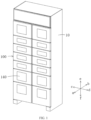
- FIG. 1 is a structural schematic view of a locker with a valve assembly according to this embodiment.
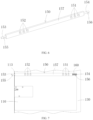
- FIG. 2 is a sectional structural schematic view of the locker with a valve assembly according to this embodiment.
- FIG. 3 is a structural schematic view taken from another angle of the locker with a valve assembly according to embodiment one of the present disclosure.
- a locker with a valve assembly includes a locker body 10 and an air supply assembly 20 disposed on the locker body 10.
- a main air duct 200 communicating with the air supply assembly 20 is disposed inside the locker body 10.
- the locker body 10 includes at least one storage box 100.
- Each storage box 100 includes a box body, a box door 140 and a valve assembly.
- the box body includes a sidewall that surrounds a circle and further includes an inner wall 130 connected to the rear end of the sidewall. The front end of the sidewall forms an opening.
- the sidewall is provided with an air vent communicating with the main air duct 200.
- the box door 140 is movably connected to the box body and has a closed position for closing the opening, and an open position for opening the opening.
- FIG. 4 is an enlarged partial view of the structure of part A of FIG. 3 .
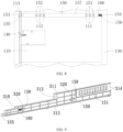
- FIG. 5 is a front view of a partial structure of a storage box of the locker with a valve assembly according to this embodiment.
- FIG. 6 is a perspective view illustrating the structure of a valve of the locker with a valve assembly according to this embodiment.
- FIG. 7 is a side view of the storage box of the locker with a valve assembly when the box door of the storage box is open according to embodiment one of the present disclosure.
- the valve assembly includes a valve 150 and a reset member 160.
- the valve 150 is configured to move relative to the sidewall.
- the box door 140 is located at the closed position
- the box door 140 is configured to drive the valve 150 to open the air vent.
- the reset member 160 is configured to drive the valve 150 to close the air vent.
- the storage box 100 further includes a safety lock 114.
- the safety lock 114 is disposed between the box body and the box door 140, and is configured to lock the box door 140 in the closed position.
- the box door 140 of the storage box 100 when the box door 140 of the storage box 100 is closed, the box door 140 is configured to drive the valve 150 to open the air vent.
- the air vent communicates with the main air duct 200.
- the air supply assembly 20 is configured to send air (such as cold air or hot air) into the main air duct 200.
- the air enters the box body through the air vent.
- the box door 140 is configured to prevent the loss of the air from the opening to an external environment.
- the reset member 160 is configured to drive the valve 150 to close the air vent to prevent the air in the main air duct 200 from entering the box body through the air vent and further losing to the external environment from the opening.
- the air supply assembly 20 may be an individual refrigeration assembly, an individual heating assembly, or an assembly with dual functions of refrigeration and heating.
- the air supply assembly 20 may be a structure similar to an air conditioner including an evaporator, an evaporator fan, a compressor, a condenser, and a condenser fan.
- the compressor, the condenser and the evaporator are sequentially in a pipeline connection to form a circuit.
- the evaporator fan is configured to blow the air around the evaporator into the main air duct 200. At this time, the air is cold.
- the cold air may enter the inside of the box body from the main air duct 200 through the air vent to cool the items stored in the box body to achieve good storage of the items.
- the condenser fan When heating is required, the condenser fan is configured to blow the air around the condenser into the main air duct 200. At this time, the air is hot. Similarly, the hot air may enter the inside of the box body from the main air duct 200 through the air vent to heat the items stored in the box body to achieve the good storage of the items.
- the refrigeration assembly or the heating assembly, or the assembly with the dual functions of refrigeration and heating is common in relevant technologies. This is not limited in the present application. As long as the cold air or the hot air can be sent to the main air duct 200.
- a plurality of storage boxes 100 may be divided into two columns and disposed in the locker body 10.
- the two columns of storage boxes 100 are bilaterally symmetric to each other.
- the main air duct 200 is disposed between the two columns of storage boxes 100.
- the air supply assembly 20 may simultaneously provide the cold air or the hot air to the left and right columns of storage boxes 100 through the main air duct 200 in the middle. In this manner, the volume of the locker body 10 is reduced, and the utilization of the space in the locker body 10 is improved.
- the shape of the storage box 100 may be a cuboid, that is, the box body of the storage box 100 includes four rectangular sidewalls connected in sequence and one rectangular inner wall.
- the shape of the storage box 100 may also be other shapes.
- the shape of the storage box 100 may also be cylindrical, that is, the box body of the storage box 100 includes one cylindrical sidewall and one circular inner wall.
- the shape of the storage box 100 is not limited in the present application.
- the sizes of a plurality of storage boxes 100 may be different. As shown in FIGS. 1 to 3 , the storage boxes 100 located in the middle have small accommodation space, and the storage boxes 100 located above and below have relatively large accommodation space. Therefore, the storage requirements of items with different volumes can be satisfied.
- the number, size and arrangement of the storage boxes 100 may be combined in different ways according to requirements to satisfy different storage requirements.
- the valve 150 is movably connected to the sidewall.
- the valve 150 includes a first end 155 and a second end 156 in the moving direction of the valve 150 and further includes an air hole between the first end 155 and the second end 156and a blocking part located between the first end 155 and the second end 156.
- the first end 155 is adjacent to the opening.
- the valve 150 has a first position for making the air hole opposite to the air vent, and a second position for making the blocking part opposite to the air vent.
- the reset member 160 When the box door 140 is located at the open position, the reset member 160 is configured to drive the valve 150 to the second position.
- the reset member 160 includes an elastic member.
- the elastic member is adjacent to the second end 156. One end of the elastic member is connected to the valve 150. Another end of the elastic member is connected to the inner wall 130.
- the elastic member is configured to make the valve 150 always have a tendency to move to the second position. With this configuration, the valve assembly is simple in structure and low in cost.
- the valve 150 includes a main body 157, a first mounting part 153 disposed at the first end 155, and a second mounting part 154 disposed at the second end 156.
- the air hole is disposed on the main body 157.
- the part of the main body 157 where the air hole is not disposed forms the blocking part.
- the box body further includes a limiting member 113 fixedly connected with the sidewall.
- the first mounting part 153 is connected to the limiting member 113 in an inserted manner.
- the second mounting part 154 is connected to the inner wall 130 in an inserted manner.
- the elastic member When the box door 140 is located at the open position, the elastic member is configured to drive the valve 150 to move towards the opening. This configuration makes it possible to avoid damage to the valve 150 due to the collision between the items, and the first end 155 of the valve 150 or the second end 156 of the valve 150, during the placement of the items into the storage box 100.
- the limiting member 113 is provided with a first mounting hole.
- the inner wall 130 is provided with a second mounting hole 131.
- the first mounting hole and the second mounting hole 131 are disposed opposite each other.
- the first mounting part 153 is inserted into the first mounting hole.
- the second mounting part 154 is inserted into the second mounting hole 131. Whether the valve 150 is located in the first position or the second position, the first mounting part 153 is always inserted into the first mounting hole, and the second mounting part 154 is always inserted into the second mounting hole 131. Thus, it is ensured that the valve 150 can be smoothly and stably switched between the first position and the second position.
- the second mounting part 154 is a strip-shaped structure that extends in a direction perpendicular to the inner wall 130.
- the elastic member is a compression spring.
- the compression spring sleeves on the second mounting part 154. One end of the compression spring and another end of the compression spring are configured to abut against the main body 157 and the inner wall 130 respectively. This configuration can make the structure of the valve assembly simple and compact.
- the sidewall includes a first sidewall 110 and a second sidewall 120 disposed opposite to each other in the width direction of the box body (that is, the left-right direction in FIG. 5 ).
- the first sidewall 110 is adjacent to the main air duct 200.
- the air vent is disposed on the first sidewall 110.
- the valve 150 is movably connected to the first sidewall 110.
- the box door 140 is pivoted to the box body through a pivot 170.
- the pivot 170 is adjacent to the second sidewall 120.
- valve 150 Since the speed of the end of the box door 140 far away from the pivot 170 is the highest during the opening of the box door 140, with this configuration, the valve 150 can close the air vent more sensitively once the box door 140 is opened. Thus, the reliability of the valve 150 is improved. Moreover, under the action of the reset member 160, the valve 150 is configured to abut against the box door 140 outwards and assist in driving the box door 140 to open quickly. In this manner, user's experience is also improved.
- the sidewall further includes a third sidewall and a fourth sidewall disposed opposite to each other in the height direction of the box body (that is, the up-down direction in FIG. 5 ).
- the first sidewall 110, the third sidewall, the second sidewall 120 and the fourth sidewall are connected in sequence.
- a valve 150 may be movably connected to any one of the second sidewall 120, the third sidewall or the fourth sidewall.
- the pivot 170 may also be adjacent to the first sidewall, the third sidewall or the fourth sidewall. Alternatively, the pivot 170 may also be directly disposed on a sidewall to make the box door 140 pivoted to a box body. In other embodiments, the box door 140 may also be connected to the box body in a slidable manner. This is not limited in the present application.
- the main air duct 200 includes an air inlet duct 210 and an air return duct 220.
- the air inlet duct 210 and the air return duct 220 extend in the up-down direction and are arranged in the front-rear direction.
- the air vent on the sidewall includes an air inlet vent 111 and an air outlet vent 112.
- the air inlet vent 111 communicates with the air inlet duct 210.
- the air outlet vent 112 communicates with the air return duct 220.
- the air hole includes an air inlet hole 151 and an air outlet hole 152.
- the air inlet hole 151 is opposite to the air inlet vent 111, and the air outlet hole 152 is opposite to the air outlet vent 112.
- the cold air or the hot air sent by the air supply assembly 20 enters the box body through the air inlet duct 210, the air inlet vent 111 and the air inlet hole 151.
- the air in the box body returns to the air supply assembly 20 through the air outlet hole 152, the air outlet vent 112 and the air return duct 220.
- the air inlet vent 111 and the air outlet vent 112 are opposite to the blocking part to prevent the cold air or the hot air in the main air duct 200 from entering the box body. Therefore, the loss of the cold air or the hot air is avoided in the case where the box door 140 is open.
- This configuration can further simplify the structure of the valve assembly and reduce the cost.
- a plurality of air inlet vents 111 are arranged apart in the moving direction of the valve 150.
- the number of air inlet holes 151 is the same as the number of the air inlet vents 111.
- each of the air inlet holes 151 is opposite to a respective one of a plurality of air inlet vents 111.
- a plurality of air outlet vents 112 are also arranged apart in the moving direction of the valve 150.
- the number of air outlet holes 152 is the same as the number of the air outlet vents 112.
- each of the air outlet holes 152 is opposite to a respective one of a plurality of air outlet vents 112.
- a plurality of air inlet vents 111 and a plurality of air inlet holes 151 are disposed, which increases the amount of inlet air, and accelerates the temperature change of the items in the box body, and is beneficial to maintain a good quality of the items.
- a plurality of air outlet vents 112 and a plurality of air outlet holes 152 are disposed, which increases the amount of return air, and air flow efficiency. Further, a guarantee is provided for maintaining the good quality of the items in the box body.
- FIG. 9 is a partial structural schematic view of a storage box of a locker with a valve assembly according to this embodiment.
- a sidewall is provided with a long groove extending in a direction perpendicular to an inner wall 130.
- a valve 150 is disposed in the long groove and configured to move between a first position and a second position along the long groove.
- the long groove is configured to support and guide the valve 150 and to make the valve 150 move smoothly between the first position and the second position along the long groove.
- the movement flexibility of the valve 150 is improved.
- the sidewall includes a housing 310.
- the long groove is formed by the housing 310.
- the housing 310 includes a first plate 311, a second plate 312 and a third plate 313 vertically connected in sequence.
- the first plate 311 and the third plate 313 are disposed opposite to each other.
- the valve 150 is located between the first plate 311 and the third plate 313. Under the joint guidance of the first plate 311 and the third plate 313, the valve 150 can move more smoothly and stably.
- the second plate 312 of the housing 310 is provided with a plurality of positioning pins 320.
- the valve 150 is provided with a plurality of limiting grooves 158.
- a plurality of limiting grooves 158 extend in the moving direction of the valve 150.
- Each of limiting grooves 158 sleeve on a respective one of a plurality of positioning pins 320.
- the reset member is a compression spring located in one limiting groove 158.
- One end of the compression spring is configured to abut against the inner wall of one limiting groove 158.
- Another end of the compression spring is configured to abut against the positioning pin 320. Under the action of the compression spring, the valve 150 always has a tendency to move to the second position.
- the second plate 312 of the housing 310 is provided with two positioning pins 320.
- the valve 150 is provided with two limiting grooves 158.
- the box door 140 When a box door 140 is located at a closed position, the box door 140 is configured to make the valve 150 move to the first position. At this time, the compression spring is compressed. An inlet hole 151 is opposite to an air inlet vent 111. The air inlet vent 111 communicates with an air inlet duct 210.
- the valve 150 When the box door 140 is located at an open position, under the action of an elastic restoring force of the compression spring, the valve 150 is configured to move to the second position where a blocking part is opposite to the air inlet vent 111. Therefore, the air inlet vent 111 is closed. Moreover, when the box door 140 is open, the force exerted by the box door 140 to the valve 150 disappears.
- the valve 150 is reset, and the air inlet vent 111 is closed.
- This configuration ensures a stable state when the valve 150 is configured to move between the first position and the second position. Moreover, the problem of loss of cold air or hot air in a main air duct 200 in the case where the operator forgets to close the door is effectively alleviated. Thus, the energy is saved.
- the first plate 311 and the third plate 313 are each provided with a hook 314.
- the opening of the hook 314 faces the inner wall 130.
- the sidewall is provided with a groove.
- the hook 314 is configured to engage with the groove in a snap-in manner.
- One end of the compression spring is configured to abut against the inner wall of the limiting groove 158 of the valve 150, and another end of the compression spring is configured to abut against the positioning pin 320. Therefore, under the action of the compression spring, the valve 150 always has a tendency to move to the second position. Under the action of the compression spring, the hook 314 of the housing 310 always maintains a tendency to engage with the groove in a snap-in manner.
- This configuration not only achieves a reliable guidance during the movement of the valve 150, but also ensures the reliability of the switching of the valve 150 between the first position and the second position. Moreover, under the action of the reset member 160, the configuration in which the housing 310 engages with the sidewall in a snap-in manner is maintained. Therefore, the mounting and the disassembly of the valve 150 can be completed without a fastener or a special tool. This configuration enables good assemblability and maintainability and simplifies the structure.
- FIG. 10 is a side view of a storage box of a locker with a valve assembly when the box door of the storage box is open according to this embodiment.
- FIG. 11 is a side view of the storage box of the locker with a valve assembly when the box door of the storage box is closed according to this embodiment. As shown in FIGS. 10 and 11 , this embodiment provides another locker with a valve assembly.
- an air inlet vent 111 and an air outlet vent 112 are disposed apart in a vertical direction;
- the valve assembly includes a first valve assembly 180 and a second valve assembly 190; when a box door 140 is located at a closed position, an air hole of the first valve assembly 180 is opposite to the air inlet vent 111, and an air hole of the second valve assembly 190 is opposite to the air outlet vent 112; and when the box door 140 is located at an open position, a blocking part of the first valve assembly 180 is opposite to the air inlet vent 111, and a blocking part of the second valve assembly 190 is opposite to the air outlet vent 112.
- the box door 140 In use, when the box door 140 is closed, the box door 140 is configured to abut against a first end 155 of a valve 150 in the first valve assembly 180, and a first end 155 of a valve 150 in the second valve assembly 190. Therefore, two valves 150 are driven to move towards an inner wall 130.
- the air hole of the first valve assembly 180 is opposite to the upper air inlet vent 111.
- the air hole of the second valve assembly 190 is opposite to the lower air outlet vent 112.
- a reset member 160 is configured to drive the valve 150 to move towards the opening, and the blocking part of the valve 150 is configured to close the air inlet vent 111.
- a reset member 160 is configured to drive the valve 150 to move towards the opening, and the blocking part of the valve 150 is configured to close the air outlet vent 112. Thus, the loss of cold air or hot air in a main air duct 200 is prevented.
- the air inlet vent 111 and the air outlet vent 112 are disposed apart in the vertical direction to make the distance between the air inlet vent 111 and the air outlet vent 112 far.
- the cold air or the hot air can more fully exchange heat with air or items in the box body. Further, a refrigeration effect or a heating effect is improved.
Landscapes
- Engineering & Computer Science (AREA)
- Chemical & Material Sciences (AREA)
- Combustion & Propulsion (AREA)
- Physics & Mathematics (AREA)
- Mechanical Engineering (AREA)
- Thermal Sciences (AREA)
- General Engineering & Computer Science (AREA)
- Cold Air Circulating Systems And Constructional Details In Refrigerators (AREA)
- Cabinets, Racks, Or The Like Of Rigid Construction (AREA)
Description
- The present application relates to the field of item storage technology, for example, a locker with a valve assembly.
- To satisfy the storage requirements of fruits, vegetables, meat, aquatic products or meals that require refrigeration and heat preservation, some lockers are provided with a refrigeration assembly or a heating assembly in a locker body. However, in the actual use of these lockers, an operator may forget to close the door after taking out items. Therefore, cold air or hot air is prone to loss. As a result, energy is wasted.
- Further relevant technologies are discussed in the patent application publications:
CN100545556C andCN1207 486 A , as well asCN 208 998 418 U andCN 205 505 562 U . In particularCN 208 998 418 U discloses a locker according to the preamble of claim 1. - The present application provides a locker with a valve assembly as defined in the annexed independent claim to alleviate the problem of easy loss of cold air or hot air in a case where an operator forgets to close the door of the locker. Further improvements are provided in the dependent claims.
- The locker with a valve assembly according to the present application includes a locker body and an air supply assembly disposed on the locker body. A main air duct communicating with the air supply assembly is disposed inside the locker body. The locker body includes at least one storage box. Each storage box includes a box body, a box door and a valve assembly. The box body includes a sidewall that surrounds a circle and further includes an inner wall connected to the rear end of the sidewall. The front end of the sidewall forms an opening. The sidewall is provided with an air vent communicating with the main air duct. The box door has a closed position for closing the opening, and an open position for opening the opening. The valve assembly includes a valve and a reset member. The valve is configured to move relative to the sidewall.
- When the box door is located at the closed position, the box door is configured to drive the valve to open the air vent. When the box door is located at the open position, the reset member is configured to drive the valve to close the air vent.
-
-
FIG. 1 is a structural schematic view of a locker with a valve assembly according to embodiment one of the present disclosure. -
FIG. 2 is a sectional structural schematic view of the locker with a valve assembly according to embodiment one of the present disclosure. -
FIG. 3 is a structural schematic view taken from another angle of the locker with a valve assembly according to embodiment one of the present disclosure. -
FIG. 4 is an enlarged partial view of the structure of part A ofFIG. 3 . -
FIG. 5 is a front view of a partial structure of a storage box of the locker with a valve assembly according to embodiment one of the present disclosure. -
FIG. 6 is a view illustrating the structure of a valve of the locker with a valve assembly according to embodiment one of the present disclosure. -
FIG. 7 is a side view of the storage box of the locker with a valve assembly when the box door of the storage box is open according to embodiment one of the present disclosure. -
FIG. 8 is a side view of the storage box of the locker with a valve assembly when the box door of the storage box is closed according to embodiment one of the present disclosure. -
FIG. 9 is a partial structural schematic view of a storage box of a locker with a valve assembly according to embodiment two of the present disclosure. -
FIG. 10 is a side view of a storage box of a locker with a valve assembly when the box door of the storage box is open according to embodiment three of the present disclosure. -
FIG. 11 is a side view of the storage box of the locker with a valve assembly when the box door of the storage box is closed according to embodiment three of the present disclosure. -
- 10
- locker body
- 20
- air supply assembly
- 100
- storage box
- 110
- first sidewall
- 111
- air inlet vent
- 112
- air outlet vent
- 113
- limiting member
- 114
- safety lock
- 120
- second sidewall
- 130
- inner wall
- 131
- second mounting hole
- 140
- box door
- 150
- valve
- 151
- air inlet hole
- 152
- air outlet hole
- 153
- first mounting part
- 154
- second mounting part
- 155
- first end
- 156
- second end
- 157
- main body
- 160
- reset member
- 170
- pivot
- 180
- first valve assembly
- 190
- second valve assembly
- 158
- limiting groove
- 310
- housing
- 311
- first plate
- 312
- second plate
- 313
- third plate
- 314
- hook
- 320
- positioning pin
- 200
- main air duct
- 210
- air inlet duct
- 220
- air return duct
- Solutions of the present application are clearly and completely described below with reference to embodiments.
- In the description of the present application, it is to be noted that orientations or positional relations indicated by terms such as "front", "rear", "up", "down", "left" and "right" are based on the drawings. These orientations or positional relations are intended only to facilitate and simplify the description of the present application and not to indicate or imply that a device or element referred to must have such particular orientations or must be configured or operated in such particular orientations. Thus, these orientations or positional relations are not to be construed as limiting the present application. Moreover, terms like "first" and "second" are merely for description and are not to be construed as indicating or implying relative importance.
- It is to be noted that in the embodiments, the direction indicated by the ab arrow in a figure represents the front-rear direction; the direction indicated by the cd arrow in the figure represents the left-right direction; and the direction indicated by the ef arrow in the figure represents the up-down direction.
-
FIG. 1 is a structural schematic view of a locker with a valve assembly according to this embodiment.FIG. 2 is a sectional structural schematic view of the locker with a valve assembly according to this embodiment.FIG. 3 is a structural schematic view taken from another angle of the locker with a valve assembly according to embodiment one of the present disclosure. - As shown in
FIGS. 1 to 3 , a locker with a valve assembly according to this embodiment includes alocker body 10 and anair supply assembly 20 disposed on thelocker body 10. Amain air duct 200 communicating with theair supply assembly 20 is disposed inside thelocker body 10. Thelocker body 10 includes at least onestorage box 100. Eachstorage box 100 includes a box body, abox door 140 and a valve assembly. The box body includes a sidewall that surrounds a circle and further includes aninner wall 130 connected to the rear end of the sidewall. The front end of the sidewall forms an opening. The sidewall is provided with an air vent communicating with themain air duct 200. Thebox door 140 is movably connected to the box body and has a closed position for closing the opening, and an open position for opening the opening.FIG. 4 is an enlarged partial view of the structure of part A ofFIG. 3 .FIG. 5 is a front view of a partial structure of a storage box of the locker with a valve assembly according to this embodiment.FIG. 6 is a perspective view illustrating the structure of a valve of the locker with a valve assembly according to this embodiment.FIG. 7 is a side view of the storage box of the locker with a valve assembly when the box door of the storage box is open according to embodiment one of the present disclosure. As shown inFIGS. 4 to 7 , the valve assembly includes avalve 150 and areset member 160. Thevalve 150 is configured to move relative to the sidewall. When thebox door 140 is located at the closed position, thebox door 140 is configured to drive thevalve 150 to open the air vent. When thebox door 140 is located at the open position, thereset member 160 is configured to drive thevalve 150 to close the air vent. - Continuing to refer to
FIG. 4 , thestorage box 100 further includes asafety lock 114. Thesafety lock 114 is disposed between the box body and thebox door 140, and is configured to lock thebox door 140 in the closed position. - During the use of the locker with a valve assembly according to this embodiment, when the
box door 140 of thestorage box 100 is closed, thebox door 140 is configured to drive thevalve 150 to open the air vent. The air vent communicates with themain air duct 200. Theair supply assembly 20 is configured to send air (such as cold air or hot air) into themain air duct 200. The air enters the box body through the air vent. Thebox door 140 is configured to prevent the loss of the air from the opening to an external environment. When thebox door 140 of thestorage box 100 is open, thereset member 160 is configured to drive thevalve 150 to close the air vent to prevent the air in themain air duct 200 from entering the box body through the air vent and further losing to the external environment from the opening. In this manner, the problem of air loss in themain air duct 200 in a case where an operator forgets to close the door is effectively alleviated. Thus, energy is saved. Moreover, cost is also reduced since a requirement for an additional driving mechanism of thevalve 150 is eliminated due to the force of closing the door. - In this embodiment, the
air supply assembly 20 may be an individual refrigeration assembly, an individual heating assembly, or an assembly with dual functions of refrigeration and heating. For example, theair supply assembly 20 may be a structure similar to an air conditioner including an evaporator, an evaporator fan, a compressor, a condenser, and a condenser fan. The compressor, the condenser and the evaporator are sequentially in a pipeline connection to form a circuit. When refrigeration is required, the evaporator fan is configured to blow the air around the evaporator into themain air duct 200. At this time, the air is cold. The cold air may enter the inside of the box body from themain air duct 200 through the air vent to cool the items stored in the box body to achieve good storage of the items. When heating is required, the condenser fan is configured to blow the air around the condenser into themain air duct 200. At this time, the air is hot. Similarly, the hot air may enter the inside of the box body from themain air duct 200 through the air vent to heat the items stored in the box body to achieve the good storage of the items. - The refrigeration assembly or the heating assembly, or the assembly with the dual functions of refrigeration and heating is common in relevant technologies. This is not limited in the present application. As long as the cold air or the hot air can be sent to the
main air duct 200. - In this embodiment, a plurality of
storage boxes 100 may be divided into two columns and disposed in thelocker body 10. The two columns ofstorage boxes 100 are bilaterally symmetric to each other. Themain air duct 200 is disposed between the two columns ofstorage boxes 100. Theair supply assembly 20 may simultaneously provide the cold air or the hot air to the left and right columns ofstorage boxes 100 through themain air duct 200 in the middle. In this manner, the volume of thelocker body 10 is reduced, and the utilization of the space in thelocker body 10 is improved. - In this embodiment, the shape of the
storage box 100 may be a cuboid, that is, the box body of thestorage box 100 includes four rectangular sidewalls connected in sequence and one rectangular inner wall. - The shape of the
storage box 100 may also be other shapes. For example, the shape of thestorage box 100 may also be cylindrical, that is, the box body of thestorage box 100 includes one cylindrical sidewall and one circular inner wall. As long as a storage function can be achieved, and the disposition requirement of the valve assembly can be satisfied, the shape of thestorage box 100 is not limited in the present application. - In this embodiment, the sizes of a plurality of
storage boxes 100 may be different. As shown inFIGS. 1 to 3 , thestorage boxes 100 located in the middle have small accommodation space, and thestorage boxes 100 located above and below have relatively large accommodation space. Therefore, the storage requirements of items with different volumes can be satisfied. - The number, size and arrangement of the
storage boxes 100 may be combined in different ways according to requirements to satisfy different storage requirements. - In this embodiment, as shown in
FIGS. 6 to 8 , thevalve 150 is movably connected to the sidewall. Thevalve 150 includes afirst end 155 and asecond end 156 in the moving direction of thevalve 150 and further includes an air hole between thefirst end 155 and the second end 156and a blocking part located between thefirst end 155 and thesecond end 156. Thefirst end 155 is adjacent to the opening. Thevalve 150 has a first position for making the air hole opposite to the air vent, and a second position for making the blocking part opposite to the air vent. When thebox door 140 is located at the closed position, thebox door 140 is configured to abut against thefirst end 155 and make thevalve 150 move to the first position. When thebox door 140 is located at the open position, thereset member 160 is configured to drive thevalve 150 to the second position. In this embodiment, thereset member 160 includes an elastic member. The elastic member is adjacent to thesecond end 156. One end of the elastic member is connected to thevalve 150. Another end of the elastic member is connected to theinner wall 130. The elastic member is configured to make thevalve 150 always have a tendency to move to the second position. With this configuration, the valve assembly is simple in structure and low in cost. - In this embodiment, continuing to refer to
FIG. 6 , thevalve 150 includes amain body 157, a first mountingpart 153 disposed at thefirst end 155, and a second mountingpart 154 disposed at thesecond end 156. The air hole is disposed on themain body 157. The part of themain body 157 where the air hole is not disposed forms the blocking part. The box body further includes a limitingmember 113 fixedly connected with the sidewall. The first mountingpart 153 is connected to the limitingmember 113 in an inserted manner. The second mountingpart 154 is connected to theinner wall 130 in an inserted manner. When thebox door 140 is located at the closed position, the first mountingpart 153 is configured to abut against thebox door 140. When thebox door 140 is located at the open position, the elastic member is configured to drive thevalve 150 to move towards the opening. This configuration makes it possible to avoid damage to thevalve 150 due to the collision between the items, and thefirst end 155 of thevalve 150 or thesecond end 156 of thevalve 150, during the placement of the items into thestorage box 100. - As shown in
FIG. 4 , the limitingmember 113 is provided with a first mounting hole. Theinner wall 130 is provided with asecond mounting hole 131. The first mounting hole and thesecond mounting hole 131 are disposed opposite each other. The first mountingpart 153 is inserted into the first mounting hole. The second mountingpart 154 is inserted into thesecond mounting hole 131. Whether thevalve 150 is located in the first position or the second position, the first mountingpart 153 is always inserted into the first mounting hole, and the second mountingpart 154 is always inserted into thesecond mounting hole 131. Thus, it is ensured that thevalve 150 can be smoothly and stably switched between the first position and the second position. - In this embodiment, continuing to refer to
FIG. 7 , the second mountingpart 154 is a strip-shaped structure that extends in a direction perpendicular to theinner wall 130. The elastic member is a compression spring. The compression spring sleeves on the second mountingpart 154. One end of the compression spring and another end of the compression spring are configured to abut against themain body 157 and theinner wall 130 respectively. This configuration can make the structure of the valve assembly simple and compact. - In this embodiment, as shown in
FIG. 5 , the sidewall includes afirst sidewall 110 and asecond sidewall 120 disposed opposite to each other in the width direction of the box body (that is, the left-right direction inFIG. 5 ). Thefirst sidewall 110 is adjacent to themain air duct 200. The air vent is disposed on thefirst sidewall 110. Thevalve 150 is movably connected to thefirst sidewall 110. As shown inFIGS. 4 and8 , thebox door 140 is pivoted to the box body through apivot 170. Thepivot 170 is adjacent to thesecond sidewall 120. When thebox door 140 is located at the closed position, the end of thebox door 140 far away from thepivot 170 is configured to abut against thefirst end 155. Since the speed of the end of thebox door 140 far away from thepivot 170 is the highest during the opening of thebox door 140, with this configuration, thevalve 150 can close the air vent more sensitively once thebox door 140 is opened. Thus, the reliability of thevalve 150 is improved. Moreover, under the action of thereset member 160, thevalve 150 is configured to abut against thebox door 140 outwards and assist in driving thebox door 140 to open quickly. In this manner, user's experience is also improved. - The sidewall further includes a third sidewall and a fourth sidewall disposed opposite to each other in the height direction of the box body (that is, the up-down direction in
FIG. 5 ). Thefirst sidewall 110, the third sidewall, thesecond sidewall 120 and the fourth sidewall are connected in sequence. In other embodiments, avalve 150 may be movably connected to any one of thesecond sidewall 120, the third sidewall or the fourth sidewall. - In other embodiments, the
pivot 170 may also be adjacent to the first sidewall, the third sidewall or the fourth sidewall. Alternatively, thepivot 170 may also be directly disposed on a sidewall to make thebox door 140 pivoted to a box body. In other embodiments, thebox door 140 may also be connected to the box body in a slidable manner. This is not limited in the present application. - In this embodiment, as shown in
FIG. 2 , themain air duct 200 includes anair inlet duct 210 and anair return duct 220. Theair inlet duct 210 and theair return duct 220 extend in the up-down direction and are arranged in the front-rear direction. As shown inFIG. 4 , the air vent on the sidewall includes anair inlet vent 111 and anair outlet vent 112. Theair inlet vent 111 communicates with theair inlet duct 210. Theair outlet vent 112 communicates with theair return duct 220. As shown inFIG. 6 , the air hole includes anair inlet hole 151 and anair outlet hole 152. When thebox door 140 is located at the closed position, theair inlet hole 151 is opposite to theair inlet vent 111, and theair outlet hole 152 is opposite to theair outlet vent 112. The cold air or the hot air sent by theair supply assembly 20 enters the box body through theair inlet duct 210, theair inlet vent 111 and theair inlet hole 151. The air in the box body returns to theair supply assembly 20 through theair outlet hole 152, theair outlet vent 112 and theair return duct 220. When thebox door 140 is located at the open position, theair inlet vent 111 and theair outlet vent 112 are opposite to the blocking part to prevent the cold air or the hot air in themain air duct 200 from entering the box body. Therefore, the loss of the cold air or the hot air is avoided in the case where thebox door 140 is open. This configuration can further simplify the structure of the valve assembly and reduce the cost. - In this embodiment, a plurality of air inlet vents 111 are arranged apart in the moving direction of the
valve 150. The number of air inlet holes 151 is the same as the number of the air inlet vents 111. When thebox door 140 is located at the closed position, each of the air inlet holes 151 is opposite to a respective one of a plurality of air inlet vents 111. A plurality of air outlet vents 112 are also arranged apart in the moving direction of thevalve 150. The number of air outlet holes 152 is the same as the number of the air outlet vents 112. When thebox door 140 is located at the closed position, each of the air outlet holes 152 is opposite to a respective one of a plurality of air outlet vents 112. - A plurality of air inlet vents 111 and a plurality of air inlet holes 151 are disposed, which increases the amount of inlet air, and accelerates the temperature change of the items in the box body, and is beneficial to maintain a good quality of the items. A plurality of air outlet vents 112 and a plurality of air outlet holes 152 are disposed, which increases the amount of return air, and air flow efficiency. Further, a guarantee is provided for maintaining the good quality of the items in the box body.
-
FIG. 9 is a partial structural schematic view of a storage box of a locker with a valve assembly according to this embodiment. As shown inFIG. 9 , in this embodiment, a sidewall is provided with a long groove extending in a direction perpendicular to aninner wall 130. Avalve 150 is disposed in the long groove and configured to move between a first position and a second position along the long groove. The long groove is configured to support and guide thevalve 150 and to make thevalve 150 move smoothly between the first position and the second position along the long groove. Thus, the movement flexibility of thevalve 150 is improved. - The sidewall includes a
housing 310. The long groove is formed by thehousing 310. Thehousing 310 includes afirst plate 311, asecond plate 312 and athird plate 313 vertically connected in sequence. Thefirst plate 311 and thethird plate 313 are disposed opposite to each other. Thevalve 150 is located between thefirst plate 311 and thethird plate 313. Under the joint guidance of thefirst plate 311 and thethird plate 313, thevalve 150 can move more smoothly and stably. - The
second plate 312 of thehousing 310 is provided with a plurality of positioning pins 320. Thevalve 150 is provided with a plurality of limitinggrooves 158. A plurality of limitinggrooves 158 extend in the moving direction of thevalve 150. Each of limitinggrooves 158 sleeve on a respective one of a plurality of positioning pins 320. The reset member is a compression spring located in one limitinggroove 158. One end of the compression spring is configured to abut against the inner wall of one limitinggroove 158. Another end of the compression spring is configured to abut against thepositioning pin 320. Under the action of the compression spring, thevalve 150 always has a tendency to move to the second position. In this embodiment, thesecond plate 312 of thehousing 310 is provided with two positioning pins 320. Thevalve 150 is provided with two limitinggrooves 158. - When a
box door 140 is located at a closed position, thebox door 140 is configured to make thevalve 150 move to the first position. At this time, the compression spring is compressed. Aninlet hole 151 is opposite to anair inlet vent 111. Theair inlet vent 111 communicates with anair inlet duct 210. When thebox door 140 is located at an open position, under the action of an elastic restoring force of the compression spring, thevalve 150 is configured to move to the second position where a blocking part is opposite to theair inlet vent 111. Therefore, theair inlet vent 111 is closed. Moreover, when thebox door 140 is open, the force exerted by thebox door 140 to thevalve 150 disappears. At this time, under the action of thereset member 160, thevalve 150 is reset, and theair inlet vent 111 is closed. This configuration ensures a stable state when thevalve 150 is configured to move between the first position and the second position. Moreover, the problem of loss of cold air or hot air in amain air duct 200 in the case where the operator forgets to close the door is effectively alleviated. Thus, the energy is saved. - The
first plate 311 and thethird plate 313 are each provided with ahook 314. The opening of thehook 314 faces theinner wall 130. Correspondingly, the sidewall is provided with a groove. Thehook 314 is configured to engage with the groove in a snap-in manner. One end of the compression spring is configured to abut against the inner wall of the limitinggroove 158 of thevalve 150, and another end of the compression spring is configured to abut against thepositioning pin 320. Therefore, under the action of the compression spring, thevalve 150 always has a tendency to move to the second position. Under the action of the compression spring, thehook 314 of thehousing 310 always maintains a tendency to engage with the groove in a snap-in manner. This configuration not only achieves a reliable guidance during the movement of thevalve 150, but also ensures the reliability of the switching of thevalve 150 between the first position and the second position. Moreover, under the action of thereset member 160, the configuration in which thehousing 310 engages with the sidewall in a snap-in manner is maintained. Therefore, the mounting and the disassembly of thevalve 150 can be completed without a fastener or a special tool. This configuration enables good assemblability and maintainability and simplifies the structure. -
FIG. 10 is a side view of a storage box of a locker with a valve assembly when the box door of the storage box is open according to this embodiment.FIG. 11 is a side view of the storage box of the locker with a valve assembly when the box door of the storage box is closed according to this embodiment. As shown inFIGS. 10 and 11 , this embodiment provides another locker with a valve assembly. The difference between this locker with a valve assembly and embodiment one is that: anair inlet vent 111 and anair outlet vent 112 are disposed apart in a vertical direction; the valve assembly includes afirst valve assembly 180 and asecond valve assembly 190; when abox door 140 is located at a closed position, an air hole of thefirst valve assembly 180 is opposite to theair inlet vent 111, and an air hole of thesecond valve assembly 190 is opposite to theair outlet vent 112; and when thebox door 140 is located at an open position, a blocking part of thefirst valve assembly 180 is opposite to theair inlet vent 111, and a blocking part of thesecond valve assembly 190 is opposite to theair outlet vent 112. - In use, when the
box door 140 is closed, thebox door 140 is configured to abut against afirst end 155 of avalve 150 in thefirst valve assembly 180, and afirst end 155 of avalve 150 in thesecond valve assembly 190. Therefore, twovalves 150 are driven to move towards aninner wall 130. The air hole of thefirst valve assembly 180 is opposite to the upperair inlet vent 111. The air hole of thesecond valve assembly 190 is opposite to the lowerair outlet vent 112. Thus, the inflow and outflow of cold air or hot air can be achieved. When thebox door 140 is opened, in thefirst valve assembly 180, areset member 160 is configured to drive thevalve 150 to move towards the opening, and the blocking part of thevalve 150 is configured to close theair inlet vent 111. In thesecond valve assembly 190, areset member 160 is configured to drive thevalve 150 to move towards the opening, and the blocking part of thevalve 150 is configured to close theair outlet vent 112. Thus, the loss of cold air or hot air in amain air duct 200 is prevented. - In addition, the
air inlet vent 111 and theair outlet vent 112 are disposed apart in the vertical direction to make the distance between theair inlet vent 111 and theair outlet vent 112 far. Thus, after the cold air or the hot air enters a box body through theair inlet vent 111 and before the cold air or the hot air flows out the box body through theair outlet vent 112, the cold air or the hot air can more fully exchange heat with air or items in the box body. Further, a refrigeration effect or a heating effect is improved. - Other features of this embodiment are the same as those of embodiment one. The technical effects of each solution have been described in embodiment one. Thus, the details are not repeated here.
Claims (15)
- A locker with a valve assembly (150,160,180,190),comprising a locker body (10) and an air supply assembly (20) disposed on the locker body (10), and a main air duct (200) communicating with the air supply assembly (20) is disposed inside the locker body (10); the locker body (10) comprises at least one storage box (100), each of the at least one storage box (100) comprises a box body, a box door (140) and the valve assembly, the box body comprises a sidewall that surrounds a circle and further comprises an inner wall (130) connected to a rear end of the sidewall, a front end of the sidewall forms an opening, and the sidewall is provided with an air vent (111,112) communicating with the
main air duct (200); the box door (140) has a closed position for closing the opening, and an open position for opening the opening; and the valve assembly comprises a valve (150) and a reset member (160), wherein the valve (150) is configured to move relative to the sidewall; andthe locker with the valve assembly is characterized in that: when the box door (140) is located at the closed position, the box door (140) is configured to drive the valve (150) to open the air vent (111,112);and when the box door (140) is located at the open position, the reset member (160) is configured to drive the valve (150) to close the air vent (111,112). - The locker with the valve assembly according to claim 1, wherein the valve (150) is movably connected to the sidewall; the valve (150) comprises a first end (155) and a second end (156) in a moving direction of the valve (150) and further comprises an air hole located between the first end (155) of the valve (150) and the second end (156) of the valve (150) and a blocking part located between the first end (155) of the valve (150) and the second end (156) of the valve (150), and the first end (155) of the valve (150) is adjacent to the opening; and the valve (150) has a first position for making the air hole opposite to the air vent, and a second position for making the blocking part opposite to the air vent; and
when the box door (140) is located at the closed position, the box door (140) is configured to abut against the first end (155) of the valve (150) and make the valve (150) move to the first position; and when the box door (140) is located at the open position, the reset member (160) is configured to drive the valve (150) to the second position. - The locker with the valve assembly according to claim 2, wherein the reset member (160) comprises an elastic member, wherein a first end of the elastic member is connected to the valve (150), a second end of the elastic member is connected to the inner wall (130) or the sidewall, and the elastic member is configured to make the valve (150) have a tendency to move to the second position.
- The locker with the valve assembly according to claim 3, wherein the valve (150) comprises a main body (157), a first mounting part (153) disposed at the first end (155) of the valve (150), and a second mounting part (154) disposed at the second end (156) of the valve (150), the air hole is disposed on the main body (157), and a part of the main body (157) where the air hole is not disposed forms the blocking part; and the box body further comprises a limiting member (113) fixedly connected with the sidewall, the first mounting part (153) is connected to the limiting member (113) in an inserted manner, and the second mounting part (154) is connected to the inner wall (130) in an inserted manner; and
when the box door (140) is located at the closed position, the first mounting part (153) is configured to abut against the box door (140), and when the box door (140) is located at the open position, the elastic member is configured to drive the valve (150) to move towards the opening. - The locker with the valve assembly according to claim 4, wherein the second mounting part (154) is a strip-shaped structure that extends in a direction perpendicular to the inner wall (130), the elastic member is a compression spring, the compression spring sleeves on the second mounting part (154), and one end of the compression spring and another end of the compression spring are configured to abut against the main body (157) and the inner wall (130) respectively.
- The locker with the valve assembly according to any one of claims 2 to 5, wherein the sidewall comprises a first sidewall (110) and a second sidewall (120) disposed opposite to each other in a width direction of the box body, wherein the first sidewall (110) is adjacent to the main air duct (200), the air vent is disposed on the first sidewall (110), and the valve (150) is movably connected to the first sidewall; and
the box door (140) is pivoted to the box body through a pivot (170), the pivot (170) is adjacent to the second sidewall (120); and when the box door (140) is located at the closed position, an end of the box door (140) far away from the pivot (170) is configured to abut against the first end (155) of the valve (150). - The locker with the valve assembly according to any one of claims 2 to 5, wherein the main air duct (200) comprises an air inlet duct (210) and an air return duct (220), and the air vent comprises an air inlet vent (111) and an air outlet vent (112), wherein the air inlet vent (111) communicates with the air inlet duct (210), and the air outlet vent (112) communicates with the air return duct (220); and
the air hole comprises an air inlet hole (151) and an air outlet hole (152), wherein when the box door (140) is located at the closed position, the air inlet hole (151) is opposite to the air inlet vent (111), and the air outlet hole (152) is opposite to the air outlet vent (112); and when the box door (140) is located at the open position, the air inlet vent (111) and the air outlet vent (112) are each opposite to the blocking part. - The locker with the valve assembly according to claim 7, wherein a plurality of air inlet vents (111) are disposed, a plurality of air inlet holes (151) are disposed, a number of the plurality of air inlet holes (151) is the same as a number of the plurality of air inlet vents (111), and when the box door (140) is located at the closed position, each of the air inlet holes (151) is opposite to a respective one of the plurality of air inlet vents (111).
- The locker with the valve assembly according to claim 7 or 8, wherein a plurality of air outlet vents (112) are disposed, a plurality of air outlet holes (152) are disposed, a number of the plurality of air outlet holes (152) is the same as a number of the plurality of air outlet vents (112), and when the box door (140) is located at the closed position, each of the air outlet holes (152) is opposite to a respective one of the plurality of air outlet vents (112).
- The locker with the valve assembly according to claim 2, wherein the main air duct (200) comprises an air inlet duct (210) and an air return duct (220), and the air vent comprises an air inlet vent (111) and an air outlet vent (112) disposed apart in a vertical direction, wherein the air inlet vent (111) communicates with the air inlet duct (210), and the air outlet vent (112) communicates with the air return duct (220); and
the valve assembly comprises a first valve assembly (180) and a second valve assembly (190), wherein when the box door (140) is located at the closed position, an air hole of the first valve assembly (180) is opposite to the air inlet vent (111), and an air hole of the second valve assembly (190) is opposite to the air outlet vent (112); and when the box door (140) is located at the open position, a blocking part of the first valve assembly (180) is opposite to the air inlet vent (111), and a blocking part of the second valve assembly (190) is opposite to the air outlet vent (112). - The locker with the valve assembly according to any one of claims 2 to 5, wherein the sidewall is provided with a long groove extending in a direction perpendicular to the inner wall (130), and the valve (150) is disposed in the long groove and configured to move between the first position and the second position along the long groove.
- The locker with the valve assembly according to claim 11, wherein the sidewall comprises a housing (310), the long groove is formed by the housing (310), and the housing (310) comprises a first plate (311), a second plate (312) and a third plate (313) vertically connected in sequence, wherein the first plate (311) and the third plate (313) are disposed opposite to each other, and the valve (150) is located between the first plate (311) and the third plate (313).
- The locker with the valve assembly according to claim 12, wherein the second plate (312) is provided with a plurality of positioning pins (320), and the valve (150) is provided with a plurality of limiting grooves (158), wherein the plurality of limiting grooves (158) extend in the moving direction of the valve (150), and each of the plurality of limiting grooves (158) sleeves on a respective one of the plurality of positioning pins (320).
- The locker with the valve assembly according to claim 13, wherein the reset member (160) is a compression spring located in one limiting groove of the plurality of limiting grooves (158), wherein one end of the compression spring is configured to abut against an inner wall of the one limiting groove (158), another end of the compression spring is configured to abut against one positioning pin (320) of the plurality of positioning pins (320) sleeved on by the one limiting groove of the plurality of limiting grooves (158), and under an action of the compression spring, the valve (150) has a tendency to move to the second position.
- The locker with the valve assembly according to claim 14, wherein the first plate (311) and the third plate (313) are each provided with a hook (314), an opening of the hook (314) faces the inner wall (130), the sidewall is provided with a groove, and the hook (314) is configured to engage with the groove in a snap-in manner.
Applications Claiming Priority (2)
| Application Number | Priority Date | Filing Date | Title |
|---|---|---|---|
| CN201910680455.5A CN112284031A (en) | 2019-07-25 | 2019-07-25 | Storage cabinet with valve assembly |
| PCT/CN2020/103821 WO2021013223A1 (en) | 2019-07-25 | 2020-07-23 | Locker having valve assembly |
Publications (4)
| Publication Number | Publication Date |
|---|---|
| EP4006468A1 EP4006468A1 (en) | 2022-06-01 |
| EP4006468A4 EP4006468A4 (en) | 2023-07-26 |
| EP4006468C0 EP4006468C0 (en) | 2025-06-18 |
| EP4006468B1 true EP4006468B1 (en) | 2025-06-18 |
Family
ID=74192824
Family Applications (1)
| Application Number | Title | Priority Date | Filing Date |
|---|---|---|---|
| EP20844871.2A Active EP4006468B1 (en) | 2019-07-25 | 2020-07-23 | Locker having valve assembly |
Country Status (4)
| Country | Link |
|---|---|
| US (1) | US12405048B2 (en) |
| EP (1) | EP4006468B1 (en) |
| CN (1) | CN112284031A (en) |
| WO (1) | WO2021013223A1 (en) |
Families Citing this family (1)
| Publication number | Priority date | Publication date | Assignee | Title |
|---|---|---|---|---|
| CN114806796A (en) * | 2022-06-08 | 2022-07-29 | 上海哥德芬会展有限公司 | A wine cellar device that is convenient for refrigeration |
Citations (1)
| Publication number | Priority date | Publication date | Assignee | Title |
|---|---|---|---|---|
| CN205505562U (en) * | 2016-03-28 | 2016-08-24 | 山东新北洋信息技术股份有限公司 | Express mail cabinet with cold -stored function |
Family Cites Families (22)
| Publication number | Priority date | Publication date | Assignee | Title |
|---|---|---|---|---|
| US1726631A (en) * | 1927-05-07 | 1929-09-03 | Earl D Sprague | Refrigerator closure |
| US2449101A (en) * | 1947-04-05 | 1948-09-14 | Lyndle W Barley | Multiple unit freezer cabinet |
| US2826475A (en) * | 1955-08-22 | 1958-03-11 | Eva H Larson | Freezer locker |
| US3089313A (en) * | 1961-09-05 | 1963-05-14 | Thomas J Fix | Refrigeration locker assembly |
| JPH05196342A (en) * | 1992-01-17 | 1993-08-06 | Hoshizaki Electric Co Ltd | Cold storage |
| KR100193707B1 (en) * | 1997-05-15 | 1999-06-15 | 윤종용 | Evaporation room shutoff device and control method of refrigerator having same |
| KR19990013175A (en) * | 1997-07-31 | 1999-02-25 | 배순훈 | Refrigerator with warm inflow prevention device |
| US6067811A (en) * | 1999-01-27 | 2000-05-30 | Shih; Shu-Yen Peng | Airtight high humidity cold storage with drawers |
| CN1252435C (en) * | 2002-08-23 | 2006-04-19 | 三星电子株式会社 | Combined refrigerator |
| CN100545556C (en) * | 2005-03-24 | 2009-09-30 | 海尔集团公司 | An air-cooled double-door refrigerator with an air curtain |
| US9434474B2 (en) * | 2012-11-16 | 2016-09-06 | B/E Aerospace, Inc. | Aircraft galley cart door interlock |
| CN105066573B (en) * | 2014-09-30 | 2018-07-13 | 松下冷链(大连)有限公司 | Refrigeration dispatching cabinet |
| CN105371564B (en) * | 2015-11-19 | 2017-12-01 | 青岛海尔股份有限公司 | Throttle setting and refrigerator for refrigerator |
| CN107240197A (en) * | 2016-03-28 | 2017-10-10 | 山东新北洋信息技术股份有限公司 | A kind of express mail cabinet |
| CN205621171U (en) * | 2016-03-28 | 2016-10-05 | 山东新北洋信息技术股份有限公司 | Express mail cabinet with cold -stored function |
| CN106546055B (en) * | 2016-11-07 | 2019-06-21 | 海信容声(广东)冰箱有限公司 | A kind of atomizing humidification device for refrigerator and refrigerator |
| CN107726699A (en) * | 2017-10-12 | 2018-02-23 | 芜湖扬宇机电技术开发有限公司 | A kind of refrigerator |
| CN108332482B (en) * | 2018-02-28 | 2021-01-01 | 海尔智家股份有限公司 | Refrigerator with a door |
| CN208541168U (en) * | 2018-04-17 | 2019-02-26 | 河源市联兴彩印有限公司 | A kind of oven case with lasting heat insulation inner wall structure |
| CN208477664U (en) * | 2018-07-03 | 2019-02-05 | 广州市南粤物流有限公司 | A kind of commodity box for material circulation based on Internet of Things |
| CN208998418U (en) * | 2018-08-08 | 2019-06-18 | 青岛海尔生物医疗股份有限公司 | A kind of refrigerator of more drawers |
| CN209054831U (en) * | 2018-09-03 | 2019-07-02 | 青岛海尔股份有限公司 | Refrigerator |
-
2019
- 2019-07-25 CN CN201910680455.5A patent/CN112284031A/en active Pending
-
2020
- 2020-07-23 WO PCT/CN2020/103821 patent/WO2021013223A1/en not_active Ceased
- 2020-07-23 EP EP20844871.2A patent/EP4006468B1/en active Active
- 2020-07-23 US US17/629,755 patent/US12405048B2/en active Active
Patent Citations (1)
| Publication number | Priority date | Publication date | Assignee | Title |
|---|---|---|---|---|
| CN205505562U (en) * | 2016-03-28 | 2016-08-24 | 山东新北洋信息技术股份有限公司 | Express mail cabinet with cold -stored function |
Also Published As
| Publication number | Publication date |
|---|---|
| US20220252322A1 (en) | 2022-08-11 |
| EP4006468C0 (en) | 2025-06-18 |
| EP4006468A1 (en) | 2022-06-01 |
| WO2021013223A1 (en) | 2021-01-28 |
| EP4006468A4 (en) | 2023-07-26 |
| CN112284031A (en) | 2021-01-29 |
| US12405048B2 (en) | 2025-09-02 |
Similar Documents
| Publication | Publication Date | Title |
|---|---|---|
| US6073789A (en) | Portable thermal container with reversible door | |
| EP3604991B1 (en) | Refrigerator | |
| KR102606132B1 (en) | Refrigerator | |
| EP3497387B1 (en) | Refrigerator | |
| EP3611452B1 (en) | Refrigerator | |
| CN102422104A (en) | refrigerator | |
| EP3994402B1 (en) | Refrigerator | |
| EP4206572B1 (en) | Refrigerator | |
| US12405048B2 (en) | Locker with valve assembly | |
| CN113028709A (en) | Refrigerator with a door | |
| CN216557835U (en) | Refrigeration device | |
| EP0893660A2 (en) | Refrigerator | |
| US20260071790A1 (en) | Refrigerator | |
| CN210180003U (en) | Storage cabinet with air inlet duct | |
| CN210625042U (en) | Refrigerator with a door | |
| CN116026093A (en) | refrigerator | |
| KR20090006505U (en) | Refrigerator | |
| EP4707711A1 (en) | Refrigerator | |
| CN110671862A (en) | Refrigerator and shelf for refrigerator | |
| JPS5922612Y2 (en) | Cooling and heating switching device for product storage in vending machines | |
| CN222733097U (en) | Air-cooled circulating system and refrigeration equipment | |
| KR20200139052A (en) | Storage box for refrigerator installed at an entrance of the place | |
| JP4379397B2 (en) | vending machine | |
| CN108088139B (en) | Laminated refrigerator | |
| KR102485761B1 (en) | A refrigerator |
Legal Events
| Date | Code | Title | Description |
|---|---|---|---|
| STAA | Information on the status of an ep patent application or granted ep patent |
Free format text: STATUS: THE INTERNATIONAL PUBLICATION HAS BEEN MADE |
|
| PUAI | Public reference made under article 153(3) epc to a published international application that has entered the european phase |
Free format text: ORIGINAL CODE: 0009012 |
|
| STAA | Information on the status of an ep patent application or granted ep patent |
Free format text: STATUS: REQUEST FOR EXAMINATION WAS MADE |
|
| 17P | Request for examination filed |
Effective date: 20220225 |
|
| AK | Designated contracting states |
Kind code of ref document: A1 Designated state(s): AL AT BE BG CH CY CZ DE DK EE ES FI FR GB GR HR HU IE IS IT LI LT LU LV MC MK MT NL NO PL PT RO RS SE SI SK SM TR |
|
| DAV | Request for validation of the european patent (deleted) | ||
| DAX | Request for extension of the european patent (deleted) | ||
| A4 | Supplementary search report drawn up and despatched |
Effective date: 20230623 |
|
| RIC1 | Information provided on ipc code assigned before grant |
Ipc: F25D 31/00 20060101AFI20230619BHEP |
|
| GRAP | Despatch of communication of intention to grant a patent |
Free format text: ORIGINAL CODE: EPIDOSNIGR1 |
|
| STAA | Information on the status of an ep patent application or granted ep patent |
Free format text: STATUS: GRANT OF PATENT IS INTENDED |
|
| INTG | Intention to grant announced |
Effective date: 20250317 |
|
| GRAS | Grant fee paid |
Free format text: ORIGINAL CODE: EPIDOSNIGR3 |
|
| GRAA | (expected) grant |
Free format text: ORIGINAL CODE: 0009210 |
|
| STAA | Information on the status of an ep patent application or granted ep patent |
Free format text: STATUS: THE PATENT HAS BEEN GRANTED |
|
| AK | Designated contracting states |
Kind code of ref document: B1 Designated state(s): AL AT BE BG CH CY CZ DE DK EE ES FI FR GB GR HR HU IE IS IT LI LT LU LV MC MK MT NL NO PL PT RO RS SE SI SK SM TR |
|
| REG | Reference to a national code |
Ref country code: GB Ref legal event code: FG4D |
|
| REG | Reference to a national code |
Ref country code: CH Ref legal event code: EP |
|
| REG | Reference to a national code |
Ref country code: DE Ref legal event code: R096 Ref document number: 602020053039 Country of ref document: DE |
|
| REG | Reference to a national code |
Ref country code: CH Ref legal event code: EP |
|
| REG | Reference to a national code |
Ref country code: IE Ref legal event code: FG4D |
|
| U01 | Request for unitary effect filed |
Effective date: 20250714 |
|
| U07 | Unitary effect registered |
Designated state(s): AT BE BG DE DK EE FI FR IT LT LU LV MT NL PT RO SE SI Effective date: 20250721 |
|
| U20 | Renewal fee for the european patent with unitary effect paid |
Year of fee payment: 6 Effective date: 20250723 |
|
| PG25 | Lapsed in a contracting state [announced via postgrant information from national office to epo] |
Ref country code: GR Free format text: LAPSE BECAUSE OF FAILURE TO SUBMIT A TRANSLATION OF THE DESCRIPTION OR TO PAY THE FEE WITHIN THE PRESCRIBED TIME-LIMIT Effective date: 20250919 Ref country code: NO Free format text: LAPSE BECAUSE OF FAILURE TO SUBMIT A TRANSLATION OF THE DESCRIPTION OR TO PAY THE FEE WITHIN THE PRESCRIBED TIME-LIMIT Effective date: 20250918 |
|
| PG25 | Lapsed in a contracting state [announced via postgrant information from national office to epo] |
Ref country code: HR Free format text: LAPSE BECAUSE OF FAILURE TO SUBMIT A TRANSLATION OF THE DESCRIPTION OR TO PAY THE FEE WITHIN THE PRESCRIBED TIME-LIMIT Effective date: 20250618 |
|
| PG25 | Lapsed in a contracting state [announced via postgrant information from national office to epo] |
Ref country code: RS Free format text: LAPSE BECAUSE OF FAILURE TO SUBMIT A TRANSLATION OF THE DESCRIPTION OR TO PAY THE FEE WITHIN THE PRESCRIBED TIME-LIMIT Effective date: 20250918 |
|
| PG25 | Lapsed in a contracting state [announced via postgrant information from national office to epo] |
Ref country code: IS Free format text: LAPSE BECAUSE OF FAILURE TO SUBMIT A TRANSLATION OF THE DESCRIPTION OR TO PAY THE FEE WITHIN THE PRESCRIBED TIME-LIMIT Effective date: 20251018 |
|
| PG25 | Lapsed in a contracting state [announced via postgrant information from national office to epo] |
Ref country code: SM Free format text: LAPSE BECAUSE OF FAILURE TO SUBMIT A TRANSLATION OF THE DESCRIPTION OR TO PAY THE FEE WITHIN THE PRESCRIBED TIME-LIMIT Effective date: 20250618 |
|
| PG25 | Lapsed in a contracting state [announced via postgrant information from national office to epo] |
Ref country code: CZ Free format text: LAPSE BECAUSE OF FAILURE TO SUBMIT A TRANSLATION OF THE DESCRIPTION OR TO PAY THE FEE WITHIN THE PRESCRIBED TIME-LIMIT Effective date: 20250618 |
|
| PG25 | Lapsed in a contracting state [announced via postgrant information from national office to epo] |
Ref country code: PL Free format text: LAPSE BECAUSE OF FAILURE TO SUBMIT A TRANSLATION OF THE DESCRIPTION OR TO PAY THE FEE WITHIN THE PRESCRIBED TIME-LIMIT Effective date: 20250618 |
|
| PG25 | Lapsed in a contracting state [announced via postgrant information from national office to epo] |
Ref country code: SK Free format text: LAPSE BECAUSE OF FAILURE TO SUBMIT A TRANSLATION OF THE DESCRIPTION OR TO PAY THE FEE WITHIN THE PRESCRIBED TIME-LIMIT Effective date: 20250618 |
|
| PG25 | Lapsed in a contracting state [announced via postgrant information from national office to epo] |
Ref country code: ES Free format text: LAPSE BECAUSE OF FAILURE TO SUBMIT A TRANSLATION OF THE DESCRIPTION OR TO PAY THE FEE WITHIN THE PRESCRIBED TIME-LIMIT Effective date: 20250618 |
|
| REG | Reference to a national code |
Ref country code: CH Ref legal event code: H13 Free format text: ST27 STATUS EVENT CODE: U-0-0-H10-H13 (AS PROVIDED BY THE NATIONAL OFFICE) Effective date: 20260224 |
|
| PG25 | Lapsed in a contracting state [announced via postgrant information from national office to epo] |
Ref country code: MC Free format text: LAPSE BECAUSE OF FAILURE TO SUBMIT A TRANSLATION OF THE DESCRIPTION OR TO PAY THE FEE WITHIN THE PRESCRIBED TIME-LIMIT Effective date: 20250618 |
|
| PG25 | Lapsed in a contracting state [announced via postgrant information from national office to epo] |
Ref country code: CH Free format text: LAPSE BECAUSE OF NON-PAYMENT OF DUE FEES Effective date: 20250731 |
|
| PLBE | No opposition filed within time limit |
Free format text: ORIGINAL CODE: 0009261 |
|
| STAA | Information on the status of an ep patent application or granted ep patent |
Free format text: STATUS: NO OPPOSITION FILED WITHIN TIME LIMIT |
|
| REG | Reference to a national code |
Ref country code: CH Ref legal event code: L10 Free format text: ST27 STATUS EVENT CODE: U-0-0-L10-L00 (AS PROVIDED BY THE NATIONAL OFFICE) Effective date: 20260430 |