EP4006335A1 - Segmented wind turbine rotor blade - Google Patents
Segmented wind turbine rotor blade Download PDFInfo
- Publication number
- EP4006335A1 EP4006335A1 EP20210363.6A EP20210363A EP4006335A1 EP 4006335 A1 EP4006335 A1 EP 4006335A1 EP 20210363 A EP20210363 A EP 20210363A EP 4006335 A1 EP4006335 A1 EP 4006335A1
- Authority
- EP
- European Patent Office
- Prior art keywords
- rotor blade
- pressure piece
- pressure
- tool
- assembly tool
- Prior art date
- Legal status (The legal status is an assumption and is not a legal conclusion. Google has not performed a legal analysis and makes no representation as to the accuracy of the status listed.)
- Granted
Links
Images





Classifications
-
- F—MECHANICAL ENGINEERING; LIGHTING; HEATING; WEAPONS; BLASTING
- F03—MACHINES OR ENGINES FOR LIQUIDS; WIND, SPRING, OR WEIGHT MOTORS; PRODUCING MECHANICAL POWER OR A REACTIVE PROPULSIVE THRUST, NOT OTHERWISE PROVIDED FOR
- F03D—WIND MOTORS
- F03D1/00—Wind motors with rotation axis substantially parallel to the air flow entering the rotor
- F03D1/06—Rotors
- F03D1/065—Rotors characterised by their construction elements
- F03D1/0675—Rotors characterised by their construction elements of the blades
- F03D1/0677—Longitudinally segmented blades; Connectors therefor
-
- F—MECHANICAL ENGINEERING; LIGHTING; HEATING; WEAPONS; BLASTING
- F03—MACHINES OR ENGINES FOR LIQUIDS; WIND, SPRING, OR WEIGHT MOTORS; PRODUCING MECHANICAL POWER OR A REACTIVE PROPULSIVE THRUST, NOT OTHERWISE PROVIDED FOR
- F03D—WIND MOTORS
- F03D1/00—Wind motors with rotation axis substantially parallel to the air flow entering the rotor
- F03D1/06—Rotors
- F03D1/065—Rotors characterised by their construction elements
- F03D1/0675—Rotors characterised by their construction elements of the blades
-
- F—MECHANICAL ENGINEERING; LIGHTING; HEATING; WEAPONS; BLASTING
- F03—MACHINES OR ENGINES FOR LIQUIDS; WIND, SPRING, OR WEIGHT MOTORS; PRODUCING MECHANICAL POWER OR A REACTIVE PROPULSIVE THRUST, NOT OTHERWISE PROVIDED FOR
- F03D—WIND MOTORS
- F03D13/00—Assembly, mounting or commissioning of wind motors; Arrangements specially adapted for transporting wind motor components
- F03D13/10—Assembly of wind motors; Arrangements for erecting wind motors
- F03D13/104—Rotor installation, e.g. installation of blades
-
- F—MECHANICAL ENGINEERING; LIGHTING; HEATING; WEAPONS; BLASTING
- F05—INDEXING SCHEMES RELATING TO ENGINES OR PUMPS IN VARIOUS SUBCLASSES OF CLASSES F01-F04
- F05B—INDEXING SCHEME RELATING TO WIND, SPRING, WEIGHT, INERTIA OR LIKE MOTORS, TO MACHINES OR ENGINES FOR LIQUIDS COVERED BY SUBCLASSES F03B, F03D AND F03G
- F05B2230/00—Manufacture
- F05B2230/60—Assembly methods
-
- F—MECHANICAL ENGINEERING; LIGHTING; HEATING; WEAPONS; BLASTING
- F05—INDEXING SCHEMES RELATING TO ENGINES OR PUMPS IN VARIOUS SUBCLASSES OF CLASSES F01-F04
- F05B—INDEXING SCHEME RELATING TO WIND, SPRING, WEIGHT, INERTIA OR LIKE MOTORS, TO MACHINES OR ENGINES FOR LIQUIDS COVERED BY SUBCLASSES F03B, F03D AND F03G
- F05B2240/00—Components
- F05B2240/20—Rotors
- F05B2240/30—Characteristics of rotor blades, i.e. of any element transforming dynamic fluid energy to or from rotational energy and being attached to a rotor
- F05B2240/302—Segmented or sectional blades
-
- Y—GENERAL TAGGING OF NEW TECHNOLOGICAL DEVELOPMENTS; GENERAL TAGGING OF CROSS-SECTIONAL TECHNOLOGIES SPANNING OVER SEVERAL SECTIONS OF THE IPC; TECHNICAL SUBJECTS COVERED BY FORMER USPC CROSS-REFERENCE ART COLLECTIONS [XRACs] AND DIGESTS
- Y02—TECHNOLOGIES OR APPLICATIONS FOR MITIGATION OR ADAPTATION AGAINST CLIMATE CHANGE
- Y02E—REDUCTION OF GREENHOUSE GAS [GHG] EMISSIONS, RELATED TO ENERGY GENERATION, TRANSMISSION OR DISTRIBUTION
- Y02E10/00—Energy generation through renewable energy sources
- Y02E10/70—Wind energy
- Y02E10/72—Wind turbines with rotation axis in wind direction
Definitions
- the invention concerns a wind turbine rotor blade with at least two rotor blade segments, a kit for connecting two rotor blade segments, a pressure piece for connecting two rotor blade segments and a method for connecting two rotor blade segments.
- Wind turbines with wind turbine rotor blades are widely known from the state of the art and are used to convert wind energy into electrical energy.
- Wind turbines comprise a multitude of components which are connected to each other, for example by means of a flange connection.
- the rotor blades comprise a rotor blade connection with a number of connecting means integrated into the laminate, via which the rotor blades are connected to a bearing ring of a so-called pitch bearing or to a component connected to the bearing ring, such as a so-called extender of the wind turbine, by means of fastening screws or fastening bolts.
- the connecting means can, for example, be designed as transverse bolts or bushings and be part of a flange insert for the rotor blade connection. Such a design is known from international application WO 2015/124568 A1 .
- (flanged) connections are also used for connecting rotor blade segments which, arranged and joined together lengthwise, form a rotor blade.
- a rotor blade is called a split or segmented rotor blade.
- connecting means are then located in the laminate of a respective connecting end or dividing flange of the rotor blade segments.
- the rotor blade segments can be connected to each other by means of bolts either directly or via suitable intermediate pieces.
- Segmented rotor blades are preferred especially for transport reasons and are becoming increasingly important, especially due to the increasing overall length of rotor blades.
- One task underlying the present invention is to specify a concept for segmented rotor blades which ensures a particularly advantageous connection of rotor blade segments.
- a wind turbine rotor blade which is formed by at least two rotor blade segments.
- the segments are screwed together at respective connection ends by means of a plurality of connecting bolts.
- sleeve-shaped pressure pieces are arranged, each of which is mounted to a connecting bolt.
- Each pressure piece comprises one or more cylindrical sections and a tool engaging section for an assembly tool.
- Each pressure piece is connected to a corresponding connecting bolt in a form fit manner, so that a screwing force can be applied to the corresponding connecting bolt by means of the assembly tool via the pressure piece.
- a diameter of the cylindrical section(s) is less than a diameter of the tool engaging section.
- Each two adjacent pressure pieces are arranged rotated by 180° relative to one another, so that - along a direction from one rotor blade segment towards the other rotor blade segment - a first axial region is formed in which cylindrical sections of the two adjacent pressure pieces lie opposite one another, a second axial region is formed in which the tool engaging portion of one of the pressure pieces opposes a cylindrical portion of the other of the pressure pieces and a third axial region is formed in which the tool engaging portion of the other of the pressure pieces opposes a cylindrical portion of the one of the pressure piece.
- these typically comprise a large number of corresponding connecting elements, such as bushings, at the connection ends to be connected.
- the connecting elements are used to create a large number of bolt connections between the two segments.
- the assembly is designed in such a way that the connecting bolts are first screwed into a connection end of one rotor blade segment, e.g. into the bushings. Then the sleeve-shaped pressure pieces are pushed onto the connecting bolts before the free ends of the connecting bolts are threaded into the corresponding connecting element of the other rotor blade segment and at least partially screwed in. Finally, the two rotor blade segments are bolted together, whereby the connection is firmly screw-bolted and pretensioned using the assembly tool. Thus, the pressure pieces are clamped between the rotor blade segments.
- the inventive wind turbine rotor blade provides pressure pieces, which have a special design regarding cylindrical sections and tool engaging sections.
- axial lengths of these sections are designed such that - for two adjacent pressure pieces - the above described three axial regions are formed. Since the diameters of the cylindrical sections and tool engaging sections of the pressure pieces are different as defined above, the alternating arrangement of the pressure pieces provides different distances between two adjacent pressure pieces along their longitudinal axes, i.e. free spaces, which are efficiently provided and used.
- the inventive solution allows an effective use of the installation space.
- a comparatively small distance of adjacent pressure sleeves to each other by same size of the assembly tool can be achieved, in particular due to the nested arrangement of the pressure pieces.
- the tool engaging sections of two adjacent pressure pieces are not opposing each other related to their longitudinal axes.
- the solution contributes to the fact that the pressure pieces require considerably less installation space.
- the small distance between the pressure pieces allows a comparatively high number of screw-connections to be made between the segments over the circumference in their connection area.
- the assembly tool not necessarily needs to be opened during a complete screwing process of one pressure piece or connecting bolt respectively. Rather, the tool can be easily repositioned in the first axial region, e.g. by rotating it in a closed state around a respective pressure piece.
- the solution enables a particularly simple and inexpensive production of pressure pieces, especially from simple semi-finished tube products. This enables particularly low manufacturing costs.
- the solution further helps to achieve a particularly rigid connection of both blade segments. It enables the absorption and transmission of particularly high tensile and compressive forces between the two rotor blade segments. Furthermore, a particularly efficient power transmission from one segment to the second segment is made possible exclusively via the connecting bolt.
- the blade segments are detachably joined without force deflection as with eccentric screw connections or intermediate pieces that are subject to tensile or bending loads. This also enables a very good material utilization. It contributes to a low tendency for the connection to slacken and to a bending load on the screw connections, especially in contrast to conventional flange connections. Furthermore, an even distance between the connecting elements, such as the bushings, and thus connecting ends to each other is ensured over the entire connection circumference.
- the assembly tool is a hydraulic torque tool, e.g. an open swing tool.
- the assembly tool can also be named mounting tool or screw tool.
- a closed state the assembly tool fully surrounds a pressure piece, at least with an engaging or wrapping part.
- the engaging part is, for example, formed in a ring-like manner.
- the open swing tool in the closed state, can be positioned in the tool engaging section of a pressure piece, such that a rotation of the assembly tool rotates the pressure piece and thus the respective connecting bolt, due to the form-fit connection of the pressure piece with the respective connecting bolt.
- the assembly tool can be opened, e.g. by opening one swing or swing arm and folding it away.
- the pressure piece is designed as a sleeve, i.e. the pressure piece comprises a continuous bore/opening along a main direction of extension, i.e. a longitudinal axis.
- the pressure piece is designed as a clamping sleeve, for example.
- a whole cylindrical section or a part of a cylindrical portion can be arranged.
- the positive-locking connections (form-fit connections) between pressure pieces and bolts are such that a torque about the longitudinal axis of a pressure piece can be transmitted to the inserted connecting bolt for screwing.
- the form-fit connections are torque-proof.
- a connecting bolt for example, is a screw bolt.
- the connecting bolt is, for example, designed as an expansion shaft bolt (with corresponding external threads).
- the connecting elements mentioned are, for example, elements laminated into the connecting ends of the blade segments. It is also conceivable that the two connecting elements are formed by dividing an overall connecting element. In this case, the rotor blade would first be manufactured as a whole, i.e. with a one-piece shell, and then separated at one point of division, for example by cutting or sawing. The separation takes place in the area of the overall connecting elements, so that two connecting element halves are created per overall connecting element, one for each of the two blade segments created by division.
- the cylindrical and tool engaging sections relate to the outer circumference of a pressure piece.
- the tool engaging section is, for example, hexagonal shaped section, wherein the assembly tool is designed accordingly to engage the pressure pieces in the respective tool engaging section.
- adjacent means directly arranged pressure pieces next to each other along the circumference of the wind turbine rotor blade.
- diameter refers to the outer diameter and in particular preferably means the maximum outside diameter in the respective area or of the respective element.
- an axial length of the first axial region corresponds to at least one width of the assembly tool.
- an axial length of the second and/or third axial region corresponds to at least one width of the assembly tool.
- a width of the tool is up to 20 to 40 mm.
- the width of the assembly tool is for example a wrench width, e.g. of a wrapping part of the open swing tool.
- the pressure pieces are each formed by a cylindrical portion comprising an axial length of at least twice the width of the mounting tool and the tool engaging portion having an axial length of at least the width of the mounting tool.
- the pressure pieces each comprise a further cylindrical portion having an axial length at least the width of the mounting tool, with the tool engaging portion being located between the two of the cylindrical portions.
- a diameter of a pressure piece in the first axial region is such that the assembly tool can freely rotate coaxially around the respective pressure piece in the first axial region, in particular the diameter is 64 mm, 74 mm, 79 mm or another value, e.g. less or more than the given values, depending on which size is necessary - however 1 mm less than a used wrench size or less.
- a free space is defined between two adjacent pressure pieces, large enough in order to allow the tool to rotate at least partially around a respective pressure piece.
- the diameter of a pressure piece in the first axial region is smaller than a wrench size of the assembly tool, which allows for the free rotation of the tool.
- the free space is just as large that the tool can be opened and closed for releasing the tool from a pressure piece or placing it onto a pressure piece. This also allows for an easy repositioning of the tool, e.g. in order to re-engage the same tool engaging section for further screwing of a same pressure piece. During repositioning, opening of the assembly tool, e.g. its surrounding or wrapping part, is not necessary. Furthermore, non-ratcheting tools possible.
- a clearance between two adjacent pressure pieces in the second and/or third axial region is smaller than a clearance in the first axial region, in particular the clearance is 10 mm or smaller.
- the clearance is large enough that the assembly tool - in a state engaging the tool engagement section - can be rotated to screw the corresponding connecting bolt.
- the clearance between two adjacent pressure pieces is maximum, in particular compared to the clearance between all remaining portions of the two adjacent pressure pieces.
- a pressure piece comprises uniformly formed cylindrical sections at opposite ends.
- the front surfaces contact surfaces to the rotor blade segments and in particular to the inserts like sleeves or bushings
- the front surfaces are dimensioned essentially identically, so that in principle, friction or contact conditions are the same on both sides of the pressure pieces.
- the plurality of pressure pieces are identically formed.
- all pressure pieces are the same, which contributes to comparatively low productions costs and makes the mounting and installation similar for all bolt connections.
- a kit for connecting two rotor blade segments of a wind turbine rotor blade is disclosed as defined in the claims.
- the kit essentially enables the above-mentioned advantages and functions.
- the kit can be further developed according to the above-mentioned embodiments with respect to the first aspect of the present disclosure. Exemplarily, several kits can be provided for all of the used bolt connections.
- a pressure piece for connecting two rotor blade segments of a wind turbine rotor blade according to any one of the above mentioned embodiments is disclosed as defined in the claims.
- the pressure piece essentially enables the above-mentioned advantages and functions.
- a method of joining two rotor blade segments of a wind turbine rotor blade according to any one of the above mentioned embodiments comprises the steps:
- the method essentially enables the above-mentioned advantages and functions.
- the assembly tool is axially displaced back into the first axial region. Then, the assembly tool is then removed and attached to the second pressure piece or the assembly tool is realigned by freely rotating it around the first pressure piece in the first axial region. In other words, the assembly tool is re-adjusted or removed from the first pressure piece to be used for the second pressure piece.
- FIG. 1 shows a schematic view of a wind turbine 100, which comprises a tower 102.
- the tower 102 is fixed to the ground by means of a foundation 104.
- a nacelle 106 is rotatably mounted.
- the nacelle 106 for example, comprises a generator which is coupled to a rotor 108 via a rotor shaft (not shown).
- the rotor 108 comprises one or more (wind turbine) rotor blades 110, which are arranged on a rotor hub 112.
- the rotor 108 is set in rotation by an air flow, for example wind. This rotational movement is transmitted to the generator via the rotor shaft and, if necessary, a gearbox.
- the generator converts the kinetic energy of the rotor 108 into electrical energy.
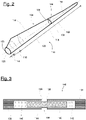
- FIG. 2 shows an exemplary wind turbine rotor blade 110.
- the rotor blade 110 has the shape of a conventional rotor blade and has a rotor blade root area 114 facing the rotor hub 112.
- the rotor blade root area 114 typically has an essentially circular cross-section.
- the rotor blade root area 114 is followed by a transition area 116 and a profile area 118 of rotor blade 110.
- the rotor blade 110 has a pressure side 122 and an opposite suction side 124 with respect to a longitudinal extension direction 120 (also main extension direction).
- the rotor blade 110 is essentially hollow inside.
- a rotor blade connection end 126 with a flange connection 128 is provided, by means of which the rotor blade 110 is mechanically connected to a pitch bearing or an extender.
- the rotor blade 110 comprises a division area 130 where a blade root-side rotor blade segment 132 and a blade tip-side rotor blade segment 134 are connected to each other.
- both segments 132, 134 each comprise a segment connection area 136, 138 (also connection ends).
- the rotor blade 110 is thus a split rotor blade as described above.
- Each connection end 136, 138 has a multitude of sleeves or bushings 140, 142, which are arranged according to the profile (in circumferential direction) and comprise internal threads for the reception of screw bolts, also called bearing bolts or connecting bolts.
- first bushings 140 comprise left-hand threads (first internal threads) and the second bushings 142 right-hand threads (second internal threads) or vice versa.
- a connection end 136, 138 is realized for example as a flange insert, which is inserted as an insert into a production mould for the manufacture of the rotor blade 110.
- no flange insert is provided and the bushings are embedded and laminated directly into the rotor blade half shells.
- the bushings are steel sleeves, for example.
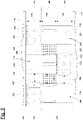
- Figure 3 shows a schematic sectional view in a partial area of two connected rotor blade segments 132, 134 at the division area 130, where a single bolt connection 148 is shown.
- the first connecting end 136 of the first rotor blade segment 132 comprises a multitude of first bushings 140 as described above.
- the second connection end 138 of the second rotor blade segment 134 comprises a number of second bushings 142.
- a connecting bolt 146 is screwed into each pair of aligned first and second bushings 140, 142. This bolt 146 connects the two connection ends 136, 138 and thus the two rotor blade segments 132, 134 mechanically.
- a pressure piece 144 is clamped between the two connection ends 136, 138 per bolt connection 148.
- FIG 4 shows a perspective view of a pressure piece 144 according to an embodiment of the invention.
- the pressure piece 144 is designed as a cylindrical sleeve and is manufactured from a simple semi-finished tube product.
- the pressure piece 144 comprises a (central) longitudinal axis 150 and a continuous bore 152 (general opening).
- the pressure piece 144 is designed to be pushed onto the connecting bolt 146 (not shown), thereby engaging the bolt 146 in a form-fit manner in order that a rotation applied to the pressure piece 144 is transferred to the bolt 146.
- the pressure piece 144 has a first axial end 154 and an opposite second axial end 156.
- the pressure piece 144 has a first cylindrical section 158, a subsequent tool engaging section 160 followed by a short second cylindrical section 162.
- An outer diameter 164 of the cylindrical sections 158, 162 is smaller than an outer diameter 166 of the tool engaging section 160.
- the cylindrical sections 158, 162 are uniformly formed and comprise the axial ends 154, 156. This guarantees the same contact conditions of the pressure piece 144 at both rotor blade segments 132, 134.
- the cylindrical section 158 comprises slots 163 serving as windows that allow a view of the connecting bolt 146 (not shown) inside the pressure piece 144.
- the tool engaging section 160 has a hexagonal outer shape in order to be engaged by a respective assembly tool, as will be described later.
- the tool engaging section 160 comprises holes 161 in the flat areas of the hexagon. The holes are provided for inserting a bolt-like assembly tool for turning the pressure piece 144 in a pre-assembling step.
- the design of the pressure piece 144 according to figure 4 enables a special, nested arrangement of several such pressure pieces 144 for the connection of two rotor blade segments as shown in figure 5 .
- FIG 5 three of such pressure pieces 144 are shown, wherein for sake of clarity, no bolts 146 or bushings 140, 142 are shown and the rotor blade segments 132 are simply indicated by dotted lines.
- Each two adjacent pressure pieces 144 are arranged 180° rotated to each other.
- the pressure pieces 144 alternate along the circumference of the rotor blade 110 with respect to their orientations.
- first segment 132 along the direction from one rotor blade segment, e.g. the first segment 132, towards the other rotor blade segment, e.g. the second segment 134, several axial regions are formed with respect to two adjacent pressure pieces 144.
- first axial region 168 only cylindrical sections (e.g. portions of the first cylindrical sections 158) of two adjacent pressure pieces are arranged, e.g. opposing each other.
- second and third axial regions 170 and 172 a respective tool engaging section 160 and a cylindrical section (e.g. portions of the first cylindrical sections 158) of the respective two adjacent pressure pieces 144 are arranged, e.g. opposing each other.
- the axial lengths 174, 176 and 178 (e.g. axial expansions) of the axial regions 168, 170 and 172 essentially correspond to at least a width 181 of an assembly tool 180, shown in figures 6 to 9 .
- the first cylindrical section 158 of a pressure piece 144 has a length of at least two times width 181 of the assembly tool 180.
- the first axial region 168 extends from the middle (dotted line) at least half the width 181 of the assembly tool 180 towards both the first and second axial ends 154, 156.
- a first clearance 182, e.g. distance, between two adjacent pressure pieces 144 in the first axial region 168 is smaller than a second clearance 184, e.g. distance, between the two adjacent pressure pieces 144 in the second and third axial regions.
- a free space 186 is formed between two adjacent pressure pieces 144, which is larger than spaces in the second and third axial regions 170, 172.
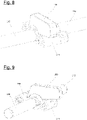
- FIGS 6 to 9 show different mounting stages of one bolt connection 148 with the help of the assembly tool 180. Again, for sake of clarity no rotor blade segments and bolts are shown. Two bushings 140, 142 are at least partially shown.
- the assembly tool 180 is a hydraulic torque tool, which has an engaging part 188, which is formed ring-like in a closed state. This engaging part 188 specifies the width 181 of the assembly tool 180 in the present embodiment.
- the assembly tool 180 can be attached to or released from a respective pressure piece 144, as is shown in figure 6 , wherein the engaging part 188 is in an opened state. In this opened state, a swing part 190 is unlocked and folded away.
- the engaging part 188 After closing the engaging part 188, the engaging part 188 fully surrounds the pressure piece 144. While in the first axial region, the assembly tool 180, e.g. the engaging part 188, can freely rotate around the cylindrical section 158 of the pressure piece. In a certain orientation, the assembly tool 180 can then be axially moved over the respective tool engaging section 160.
- the assembly tool 180 e.g. the engaging part 188
- Figure 8 shows the state in which the assembly tool 180 engages the pressure piece 144 in order to apply a screwing force onto the pressure piece 144.
- the assembly tool 180 can by axially moved back into the first axial region 168 in order to be released or rotated for repositioning to be again moved onto the tool engaging portion 160.
- At least two bolts 146 and at least two pressure pieces 144 form together a kit or assembly kit for mounting two rotor blade segments.
- Figures 10a to 10d show an exemplary method for connecting two segments 132, 134 with the help of the flow chart of figure 11 according to an embodiment of the invention.
- connection bolts 146 are partially screwed into the first connection end 136 of the first rotor blade segment 132, in particular into first bushings 140, in such a way that the connecting bolts 146 project from the first connection end 136 (not shown).
- the sleeve-shaped pressure pieces 144 are provided as described above (not shown).
- the pressure pieces 144 are mounted to the connecting bolts 146 in a form-fit manner, wherein that two adjacent pressure pieces are arranged in each case rotated by 180° relative to one another (please refer to Figures 10a to 10d , exemplarily showing this arrangement).
- step S4 the second connection end 138 of the second rotor blade segment 134 is brought close to the first connection end 136 of the first rotor blade segment 132 (not shown).
- step S5 the connecting bolts 146 are partially screwed into the second connection end 138 of the second rotor blade segment 134, in particular into second bushings 142 (not shown).
- the assembly tool 180 is attached to a first pressure piece 144 in the first axial region 168 relative to an adjacent second pressure piece 144 (see also figures 6 and 7 ).
- step S7 the assembly tool 180 is aligned and axially moved along the first pressure piece 144 such that the assembly tool 180 engages the first pressure piece 144 in the tool engaging portion 160 (see figure 10a and figure 8 ). Thus, the tool 180 is moved into the second axial region 170.
- step S8 the corresponding connecting bolt 146 (not shown) is screw at least partially by using the assembly tool 180 (see figure 10a ).
- step S9 the assembly tool 180 is axially moved back into the first axial region 168 (see figure 10b ).
- step S10 the assembly tool 180 is repositioned in the first axial region 168(free rotation around the cylindrical part of the pressure piece 144) and steps S7 to S9 are repeated.
- the assembly tool 180 is detached from the first pressure piece 144 and attached to the next, second pressure piece 144 (see figure 10c ).
- steps S7 to S9 and possibly S10 are repeated, with the difference, that the tool 180 is moved to the third axial region in step S7 for screwing the respective pressure piece 144/bolt 146 (see figure 10d ).
- the pressure pieces 144 can be arranged very close to each other, while still the access and screwing by the assembly tool 180 is possible.
- all pressure pieces 144 are formed identically.
Landscapes
- Engineering & Computer Science (AREA)
- Life Sciences & Earth Sciences (AREA)
- Sustainable Development (AREA)
- Sustainable Energy (AREA)
- Chemical & Material Sciences (AREA)
- Combustion & Propulsion (AREA)
- Mechanical Engineering (AREA)
- General Engineering & Computer Science (AREA)
- Wind Motors (AREA)
Abstract
Description
- The invention concerns a wind turbine rotor blade with at least two rotor blade segments, a kit for connecting two rotor blade segments, a pressure piece for connecting two rotor blade segments and a method for connecting two rotor blade segments.
- Wind turbines with wind turbine rotor blades are widely known from the state of the art and are used to convert wind energy into electrical energy. Wind turbines comprise a multitude of components which are connected to each other, for example by means of a flange connection. For example, in the area of a rotor blade root, the rotor blades comprise a rotor blade connection with a number of connecting means integrated into the laminate, via which the rotor blades are connected to a bearing ring of a so-called pitch bearing or to a component connected to the bearing ring, such as a so-called extender of the wind turbine, by means of fastening screws or fastening bolts. The connecting means can, for example, be designed as transverse bolts or bushings and be part of a flange insert for the rotor blade connection. Such a design is known from international application
WO 2015/124568 A1 . - Alternatively, (flanged) connections are also used for connecting rotor blade segments which, arranged and joined together lengthwise, form a rotor blade. Such a rotor blade is called a split or segmented rotor blade. For example, connecting means are then located in the laminate of a respective connecting end or dividing flange of the rotor blade segments. The rotor blade segments can be connected to each other by means of bolts either directly or via suitable intermediate pieces.
- Segmented rotor blades are preferred especially for transport reasons and are becoming increasingly important, especially due to the increasing overall length of rotor blades.
- One task underlying the present invention is to specify a concept for segmented rotor blades which ensures a particularly advantageous connection of rotor blade segments.
- According to a first aspect a wind turbine rotor blade is disclosed, which is formed by at least two rotor blade segments. The segments are screwed together at respective connection ends by means of a plurality of connecting bolts. Between the rotor blade segments sleeve-shaped pressure pieces are arranged, each of which is mounted to a connecting bolt. Each pressure piece comprises one or more cylindrical sections and a tool engaging section for an assembly tool. Each pressure piece is connected to a corresponding connecting bolt in a form fit manner, so that a screwing force can be applied to the corresponding connecting bolt by means of the assembly tool via the pressure piece. A diameter of the cylindrical section(s) is less than a diameter of the tool engaging section. Each two adjacent pressure pieces are arranged rotated by 180° relative to one another, so that - along a direction from one rotor blade segment towards the other rotor blade segment - a first axial region is formed in which cylindrical sections of the two adjacent pressure pieces lie opposite one another, a second axial region is formed in which the tool engaging portion of one of the pressure pieces opposes a cylindrical portion of the other of the pressure pieces and a third axial region is formed in which the tool engaging portion of the other of the pressure pieces opposes a cylindrical portion of the one of the pressure piece.
- For connecting the two rotor blade segments of a wind turbine rotor blade, these typically comprise a large number of corresponding connecting elements, such as bushings, at the connection ends to be connected. The connecting elements are used to create a large number of bolt connections between the two segments. The assembly is designed in such a way that the connecting bolts are first screwed into a connection end of one rotor blade segment, e.g. into the bushings. Then the sleeve-shaped pressure pieces are pushed onto the connecting bolts before the free ends of the connecting bolts are threaded into the corresponding connecting element of the other rotor blade segment and at least partially screwed in. Finally, the two rotor blade segments are bolted together, whereby the connection is firmly screw-bolted and pretensioned using the assembly tool. Thus, the pressure pieces are clamped between the rotor blade segments.
- The inventive wind turbine rotor blade provides pressure pieces, which have a special design regarding cylindrical sections and tool engaging sections. In particular, axial lengths of these sections are designed such that - for two adjacent pressure pieces - the above described three axial regions are formed. Since the diameters of the cylindrical sections and tool engaging sections of the pressure pieces are different as defined above, the alternating arrangement of the pressure pieces provides different distances between two adjacent pressure pieces along their longitudinal axes, i.e. free spaces, which are efficiently provided and used.
- This arrangement provides a lot of advantages as explained in the following.
- The inventive solution allows an effective use of the installation space. In particular, a comparatively small distance of adjacent pressure sleeves to each other by same size of the assembly tool can be achieved, in particular due to the nested arrangement of the pressure pieces. In such nested arrangement, the tool engaging sections of two adjacent pressure pieces are not opposing each other related to their longitudinal axes. Thus, the solution contributes to the fact that the pressure pieces require considerably less installation space. As a result, the small distance between the pressure pieces allows a comparatively high number of screw-connections to be made between the segments over the circumference in their connection area.
- Furthermore, a shorter installation time can be achieved, since the assembly tool not necessarily needs to be opened during a complete screwing process of one pressure piece or connecting bolt respectively. Rather, the tool can be easily repositioned in the first axial region, e.g. by rotating it in a closed state around a respective pressure piece.
- Further, the solution enables a particularly simple and inexpensive production of pressure pieces, especially from simple semi-finished tube products. This enables particularly low manufacturing costs.
- The solution further helps to achieve a particularly rigid connection of both blade segments. It enables the absorption and transmission of particularly high tensile and compressive forces between the two rotor blade segments. Furthermore, a particularly efficient power transmission from one segment to the second segment is made possible exclusively via the connecting bolt. In other words, the blade segments are detachably joined without force deflection as with eccentric screw connections or intermediate pieces that are subject to tensile or bending loads. This also enables a very good material utilization. It contributes to a low tendency for the connection to slacken and to a bending load on the screw connections, especially in contrast to conventional flange connections. Furthermore, an even distance between the connecting elements, such as the bushings, and thus connecting ends to each other is ensured over the entire connection circumference.
- For example, the assembly tool is a hydraulic torque tool, e.g. an open swing tool. The assembly tool can also be named mounting tool or screw tool. In a closed state the assembly tool fully surrounds a pressure piece, at least with an engaging or wrapping part. The engaging part is, for example, formed in a ring-like manner. For example, in the closed state, the open swing tool can be positioned in the tool engaging section of a pressure piece, such that a rotation of the assembly tool rotates the pressure piece and thus the respective connecting bolt, due to the form-fit connection of the pressure piece with the respective connecting bolt. The assembly tool can be opened, e.g. by opening one swing or swing arm and folding it away.
- The pressure piece is designed as a sleeve, i.e. the pressure piece comprises a continuous bore/opening along a main direction of extension, i.e. a longitudinal axis. The pressure piece is designed as a clamping sleeve, for example.
- In an axial region, a whole cylindrical section or a part of a cylindrical portion can be arranged.
- The positive-locking connections (form-fit connections) between pressure pieces and bolts are such that a torque about the longitudinal axis of a pressure piece can be transmitted to the inserted connecting bolt for screwing. In other words, the form-fit connections are torque-proof.
- A connecting bolt, for example, is a screw bolt. The connecting bolt is, for example, designed as an expansion shaft bolt (with corresponding external threads).
- The connecting elements mentioned, such as the bushings, are, for example, elements laminated into the connecting ends of the blade segments. It is also conceivable that the two connecting elements are formed by dividing an overall connecting element. In this case, the rotor blade would first be manufactured as a whole, i.e. with a one-piece shell, and then separated at one point of division, for example by cutting or sawing. The separation takes place in the area of the overall connecting elements, so that two connecting element halves are created per overall connecting element, one for each of the two blade segments created by division.
- The cylindrical and tool engaging sections relate to the outer circumference of a pressure piece. The tool engaging section is, for example, hexagonal shaped section, wherein the assembly tool is designed accordingly to engage the pressure pieces in the respective tool engaging section.
- The term adjacent means directly arranged pressure pieces next to each other along the circumference of the wind turbine rotor blade.
- The term diameter refers to the outer diameter and in particular preferably means the maximum outside diameter in the respective area or of the respective element.
- According to an embodiment an axial length of the first axial region corresponds to at least one width of the assembly tool.
- According to an embodiment an axial length of the second and/or third axial region corresponds to at least one width of the assembly tool.
- According to an embodiment a width of the tool is up to 20 to 40 mm. The width of the assembly tool is for example a wrench width, e.g. of a wrapping part of the open swing tool.
- According to an embodiment the pressure pieces are each formed by a cylindrical portion comprising an axial length of at least twice the width of the mounting tool and the tool engaging portion having an axial length of at least the width of the mounting tool. This is a possible, easy to produce solution enabling the above mentioned functions and advantages.
- According to an embodiment the pressure pieces each comprise a further cylindrical portion having an axial length at least the width of the mounting tool, with the tool engaging portion being located between the two of the cylindrical portions. This is a further possible solution for a pressure piece, wherein, for example, for two adjacent pressure pieces two first axial regions are formed, which allow for mounting/releasing or repositioning of the assembly tool.
- According to an embodiment a diameter of a pressure piece in the first axial region is such that the assembly tool can freely rotate coaxially around the respective pressure piece in the first axial region, in particular the diameter is 64 mm, 74 mm, 79 mm or another value, e.g. less or more than the given values, depending on which size is necessary - however 1 mm less than a used wrench size or less. Thus, a free space is defined between two adjacent pressure pieces, large enough in order to allow the tool to rotate at least partially around a respective pressure piece.
- As an example, the diameter of a pressure piece in the first axial region is smaller than a wrench size of the assembly tool, which allows for the free rotation of the tool. Further, the free space is just as large that the tool can be opened and closed for releasing the tool from a pressure piece or placing it onto a pressure piece. This also allows for an easy repositioning of the tool, e.g. in order to re-engage the same tool engaging section for further screwing of a same pressure piece. During repositioning, opening of the assembly tool, e.g. its surrounding or wrapping part, is not necessary. Furthermore, non-ratcheting tools possible.
- According to an embodiment a clearance between two adjacent pressure pieces in the second and/or third axial region is smaller than a clearance in the first axial region, in particular the clearance is 10 mm or smaller.
- The clearance is large enough that the assembly tool - in a state engaging the tool engagement section - can be rotated to screw the corresponding connecting bolt.
- According to an embodiment, in the first axial region the clearance between two adjacent pressure pieces is maximum, in particular compared to the clearance between all remaining portions of the two adjacent pressure pieces.
- According to an embodiment a pressure piece comprises uniformly formed cylindrical sections at opposite ends. Thus, the front surfaces (contact surfaces to the rotor blade segments and in particular to the inserts like sleeves or bushings) are dimensioned essentially identically, so that in principle, friction or contact conditions are the same on both sides of the pressure pieces.
- According to an embodiment the plurality of pressure pieces are identically formed. Thus, all pressure pieces are the same, which contributes to comparatively low productions costs and makes the mounting and installation similar for all bolt connections.
- According to a further aspect, a kit for connecting two rotor blade segments of a wind turbine rotor blade is disclosed as defined in the claims.
- The kit essentially enables the above-mentioned advantages and functions. The kit can be further developed according to the above-mentioned embodiments with respect to the first aspect of the present disclosure. Exemplarily, several kits can be provided for all of the used bolt connections.
- According to a further aspect, a pressure piece for connecting two rotor blade segments of a wind turbine rotor blade according to any one of the above mentioned embodiments is disclosed as defined in the claims. The pressure piece essentially enables the above-mentioned advantages and functions.
- According to a further aspect, a method of joining two rotor blade segments of a wind turbine rotor blade according to any one of the above mentioned embodiments is disclosed. The method comprises the steps:
- partially screwing connecting bolts into the first connection end of the first rotor blade segment in such a way that the connecting bolts project from the first connection end,
- providing sleeve-shaped pressure pieces, each comprising one or more cylindrical portions and a tool engaging portion for an assembly tool, and wherein a diameter of the cylindrical portion(s) is less than a diameter of the tool engaging portion,
- form-fit mounting of the pressure pieces to the connecting bolts in such a way that two adjacent pressure pieces are arranged in each case rotated by 180° relative to one another,
- bringing the second connection end of the second rotor blade segment close to the first connection end of the first rotor blade segment,
- partially screwing the connecting bolts into the second connection end,
- attaching an assembly tool to a first pressure piece in the first axial region relative to an adjacent second pressure piece,
- aligning and axially moving the assembly tool along the first pressure piece such that the assembly tool engages the first pressure piece in the tool engaging portion; and
- screwing the corresponding connecting bolt using the assembly tool.
- The method essentially enables the above-mentioned advantages and functions.
- According to an embodiment, after the screwing step, the assembly tool is axially displaced back into the first axial region. Then, the assembly tool is then removed and attached to the second pressure piece or the assembly tool is realigned by freely rotating it around the first pressure piece in the first axial region. In other words, the assembly tool is re-adjusted or removed from the first pressure piece to be used for the second pressure piece.
- Further advantages, features and functions are given in the following exemplary embodiment of the invention, which are explained in connection with the figures. Identical, similar or similarly acting elements are provided with the same reference signs in the figures.
- In the figures:
-
Figure 1 shows a schematic view of a wind turbine, -
Figure 2 shows a schematic view of a split rotor blade with two rotor blade segments, -
Figure 3 shows a schematic sectional view of an exemplary bolt connection of two rotor blade segments, -
Figure 4 shows a pressure piece according to an embodiment of the invention, -
Figure 5 shows an exemplary arrangement of three pressure pieces ofFigure 4 for connection of two rotor blade segments according to an embodiment of the invention, -
Figures 6 to 9 show perspective views of different stages of mounting with an assembly tool according to an embodiment of the invention, -
Figures 10a to 10d show an exemplary installation procedure according to an embodiment of the invention, and -
Figure 11 shows a schematic flow chart of a method for joining two rotor blade segments according to an embodiment of the invention. -
Figure 1 shows a schematic view of awind turbine 100, which comprises atower 102. Thetower 102 is fixed to the ground by means of afoundation 104. At one end of thetower 102 opposite to the ground anacelle 106 is rotatably mounted. Thenacelle 106, for example, comprises a generator which is coupled to arotor 108 via a rotor shaft (not shown). Therotor 108 comprises one or more (wind turbine)rotor blades 110, which are arranged on arotor hub 112. - During operation, the
rotor 108 is set in rotation by an air flow, for example wind. This rotational movement is transmitted to the generator via the rotor shaft and, if necessary, a gearbox. The generator converts the kinetic energy of therotor 108 into electrical energy. -
Figure 2 shows an exemplary windturbine rotor blade 110. Therotor blade 110 has the shape of a conventional rotor blade and has a rotorblade root area 114 facing therotor hub 112. The rotorblade root area 114 typically has an essentially circular cross-section. The rotorblade root area 114 is followed by atransition area 116 and aprofile area 118 ofrotor blade 110. Therotor blade 110 has apressure side 122 and anopposite suction side 124 with respect to a longitudinal extension direction 120 (also main extension direction). Therotor blade 110 is essentially hollow inside. - In the rotor blade root area 114 a rotor
blade connection end 126 with aflange connection 128 is provided, by means of which therotor blade 110 is mechanically connected to a pitch bearing or an extender. - The
rotor blade 110 comprises adivision area 130 where a blade root-siderotor blade segment 132 and a blade tip-siderotor blade segment 134 are connected to each other. For this purpose, bothsegments segment connection area 136, 138 (also connection ends). Therotor blade 110 is thus a split rotor blade as described above. Eachconnection end bushings first bushings 140 comprise left-hand threads (first internal threads) and thesecond bushings 142 right-hand threads (second internal threads) or vice versa. Aconnection end rotor blade 110. However, it is also conceivable that no flange insert is provided and the bushings are embedded and laminated directly into the rotor blade half shells. The bushings are steel sleeves, for example. - In the following, the connection of both
rotor blade segments -
Figure 3 shows a schematic sectional view in a partial area of two connectedrotor blade segments division area 130, where asingle bolt connection 148 is shown. The first connectingend 136 of the firstrotor blade segment 132 comprises a multitude offirst bushings 140 as described above. Thesecond connection end 138 of the secondrotor blade segment 134 comprises a number ofsecond bushings 142. A connectingbolt 146 is screwed into each pair of aligned first andsecond bushings bolt 146 connects the two connection ends 136, 138 and thus the tworotor blade segments pressure piece 144 is clamped between the two connection ends 136, 138 perbolt connection 148. -
Figure 4 shows a perspective view of apressure piece 144 according to an embodiment of the invention. Thepressure piece 144 is designed as a cylindrical sleeve and is manufactured from a simple semi-finished tube product. Thepressure piece 144 comprises a (central)longitudinal axis 150 and a continuous bore 152 (general opening). Thepressure piece 144 is designed to be pushed onto the connecting bolt 146 (not shown), thereby engaging thebolt 146 in a form-fit manner in order that a rotation applied to thepressure piece 144 is transferred to thebolt 146. Thepressure piece 144 has a firstaxial end 154 and an opposite secondaxial end 156. Starting from the firstaxial end 154, thepressure piece 144 has a firstcylindrical section 158, a subsequenttool engaging section 160 followed by a short secondcylindrical section 162. Anouter diameter 164 of thecylindrical sections outer diameter 166 of thetool engaging section 160. In the present embodiment, thecylindrical sections pressure piece 144 at bothrotor blade segments cylindrical section 158 comprisesslots 163 serving as windows that allow a view of the connecting bolt 146 (not shown) inside thepressure piece 144. - The
tool engaging section 160 has a hexagonal outer shape in order to be engaged by a respective assembly tool, as will be described later. Thetool engaging section 160 comprisesholes 161 in the flat areas of the hexagon. The holes are provided for inserting a bolt-like assembly tool for turning thepressure piece 144 in a pre-assembling step. - The design of the
pressure piece 144 according tofigure 4 enables a special, nested arrangement of severalsuch pressure pieces 144 for the connection of two rotor blade segments as shown infigure 5 . Infigure 5 , three ofsuch pressure pieces 144 are shown, wherein for sake of clarity, nobolts 146 orbushings rotor blade segments 132 are simply indicated by dotted lines. Each twoadjacent pressure pieces 144 are arranged 180° rotated to each other. Thus, thepressure pieces 144 alternate along the circumference of therotor blade 110 with respect to their orientations. - By this arrangement, along the direction from one rotor blade segment, e.g. the
first segment 132, towards the other rotor blade segment, e.g. thesecond segment 134, several axial regions are formed with respect to twoadjacent pressure pieces 144. In a firstaxial region 168 only cylindrical sections (e.g. portions of the first cylindrical sections 158) of two adjacent pressure pieces are arranged, e.g. opposing each other. In second and thirdaxial regions 170 and 172 a respectivetool engaging section 160 and a cylindrical section (e.g. portions of the first cylindrical sections 158) of the respective twoadjacent pressure pieces 144 are arranged, e.g. opposing each other. - The
axial lengths axial regions width 181 of anassembly tool 180, shown infigures 6 to 9 . In other words, the firstcylindrical section 158 of apressure piece 144 has a length of at least twotimes width 181 of theassembly tool 180. In other words, in the presently shown embodiment the firstaxial region 168 extends from the middle (dotted line) at least half thewidth 181 of theassembly tool 180 towards both the first and second axial ends 154, 156. - A
first clearance 182, e.g. distance, between twoadjacent pressure pieces 144 in the firstaxial region 168 is smaller than asecond clearance 184, e.g. distance, between the twoadjacent pressure pieces 144 in the second and third axial regions. Thus, in the first axial region 168 afree space 186 is formed between twoadjacent pressure pieces 144, which is larger than spaces in the second and thirdaxial regions -
Figures 6 to 9 show different mounting stages of onebolt connection 148 with the help of theassembly tool 180. Again, for sake of clarity no rotor blade segments and bolts are shown. Twobushings assembly tool 180 is a hydraulic torque tool, which has anengaging part 188, which is formed ring-like in a closed state. Thisengaging part 188 specifies thewidth 181 of theassembly tool 180 in the present embodiment. - In the first axial region, the
assembly tool 180 can be attached to or released from arespective pressure piece 144, as is shown infigure 6 , wherein theengaging part 188 is in an opened state. In this opened state, aswing part 190 is unlocked and folded away. - With respect to
figure 7 , after closing theengaging part 188, theengaging part 188 fully surrounds thepressure piece 144. While in the first axial region, theassembly tool 180, e.g. theengaging part 188, can freely rotate around thecylindrical section 158 of the pressure piece. In a certain orientation, theassembly tool 180 can then be axially moved over the respectivetool engaging section 160. -
Figure 8 shows the state in which theassembly tool 180 engages thepressure piece 144 in order to apply a screwing force onto thepressure piece 144. - With respect to
figure 9 , after having rotated thepressure piece 144 for screwing thecorresponding bolt 146, theassembly tool 180 can by axially moved back into the firstaxial region 168 in order to be released or rotated for repositioning to be again moved onto thetool engaging portion 160. - At this point, it is noted that at least two
bolts 146 and at least twopressure pieces 144 form together a kit or assembly kit for mounting two rotor blade segments. -
Figures 10a to 10d show an exemplary method for connecting twosegments figure 11 according to an embodiment of the invention. - In a first step S1,
connection bolts 146 are partially screwed into thefirst connection end 136 of the firstrotor blade segment 132, in particular intofirst bushings 140, in such a way that the connectingbolts 146 project from the first connection end 136 (not shown). - In a further step S2, the sleeve-shaped
pressure pieces 144 are provided as described above (not shown). - In a further step S3, the
pressure pieces 144 are mounted to the connectingbolts 146 in a form-fit manner, wherein that two adjacent pressure pieces are arranged in each case rotated by 180° relative to one another (please refer toFigures 10a to 10d , exemplarily showing this arrangement). - In a further step S4, the
second connection end 138 of the secondrotor blade segment 134 is brought close to thefirst connection end 136 of the first rotor blade segment 132 (not shown). - In a further step S5, the connecting
bolts 146 are partially screwed into thesecond connection end 138 of the secondrotor blade segment 134, in particular into second bushings 142 (not shown). - In a further step S6, the
assembly tool 180 is attached to afirst pressure piece 144 in the firstaxial region 168 relative to an adjacent second pressure piece 144 (see alsofigures 6 and 7 ). - In a further step S7, the
assembly tool 180 is aligned and axially moved along thefirst pressure piece 144 such that theassembly tool 180 engages thefirst pressure piece 144 in the tool engaging portion 160 (seefigure 10a andfigure 8 ). Thus, thetool 180 is moved into the secondaxial region 170. - In a further step S8, the corresponding connecting bolt 146 (not shown) is screw at least partially by using the assembly tool 180 (see
figure 10a ). - In a further step S9, the
assembly tool 180 is axially moved back into the first axial region 168 (seefigure 10b ). - If necessary, in a further step S10, the
assembly tool 180 is repositioned in the first axial region 168(free rotation around the cylindrical part of the pressure piece 144) and steps S7 to S9 are repeated. - Otherwise, in a further step S11, the
assembly tool 180 is detached from thefirst pressure piece 144 and attached to the next, second pressure piece 144 (seefigure 10c ). - Now, steps S7 to S9 and possibly S10 are repeated, with the difference, that the
tool 180 is moved to the third axial region in step S7 for screwing therespective pressure piece 144/bolt 146 (seefigure 10d ). - The embodiments as described above enables the functions, effects and advantages as listed in the introductory part of this writing. In particular, the
pressure pieces 144 can be arranged very close to each other, while still the access and screwing by theassembly tool 180 is possible. Here it is noted that in the shown and described embodiments allpressure pieces 144 are formed identically. -
- 100
- wind turbine
- 102
- tower
- 104
- foundation
- 106
- nacelle
- 108
- rotor
- 110
- rotor blade
- 112
- rotor hub
- 114
- rotor blade root area
- 116
- transition area
- 118
- profile area
- 120
- longitudinal extension direction
- 122
- pressure side
- 124
- suction side
- 126
- rotor blade connection end
- 128
- flange connection
- 130
- division area
- 132
- first rotor blade segment
- 134
- second rotor blade segment
- 136
- first connection end
- 138
- second connection end
- 140
- first bushing
- 142
- second bushing
- 144
- pressure piece
- 146
- connection bolt
- 148
- bolt connection
- 150
- longitudinal axis
- 152
- bore
- 154
- first axial end
- 156
- second axial end
- 158
- first cylindrical section
- 160
- tool engaging section
- 161
- hole
- 162
- second cylindrical section
- 163
- slotted hole
- 164
- outer diameter
- 166
- outer diameter
- 168
- first axial region
- 170
- second axial region
- 172
- third axial region
- 174-178
- axial length
- 180
- assembly tool
- 181
- width
- 182
- first clearance
- 184
- second clearance
- 186
- free space
- 188
- engaging part
- 190
- swing part
- S1 - S11
- steps
Claims (15)
- Wind turbine rotor blade (110), which is formed by at least two rotor blade segments (132, 134), said segments (132, 134) screwed together at respective connection ends(136, 138) by means of a plurality of connecting bolts (146), wherein
sleeve-shaped pressure pieces (144) are arranged between the rotor blade segments (132, 134), each of which is mounted on a connecting bolt (146),
each pressure piece (144) comprises one or more cylindrical sections (158, 162) and a tool engaging section (160) for an assembly tool (180),
each pressure piece (144) is connected to a corresponding connecting bolt (146) in a form fit manner, so that a screwing force can be applied to the corresponding connecting bolt (146) by means of the assembly tool (180) via the pressure piece (144),
a diameter (164) of the cylindrical section(s) (158, 162) is less than a diameter (166) of the tool engaging section (160), and
each two adjacent pressure pieces (144) are arranged rotated by 180° relative to one another, so that in the case of adjacent pressure pieces (144) - in a direction of one rotor blade segment (132, 134) towards the other rotor blade segment (132, 134) - a first axial region (168) is formed, in which cylindrical sections (158, 162) of the two pressure pieces (144) are opposite one another, a second axial region (170) is formed, in which the tool engaging portion (160) of one pressure piece (144) is opposed to a cylindrical portion (158, 162) of the other pressure piece (144), and a third axial region (172) is formed, in which the tool engaging portion (160) of the other pressure piece (144) is opposed to a cylindrical portion (158, 162) of the one pressure piece (144) . - The wind turbine rotor blade (110) according to claim 1, wherein an axial length (174) of the first axial region (168) corresponds to at least a width (181) of the assembly tool (180) .
- The wind turbine rotor blade (110) according to claim 1 or 2, wherein an axial length (176, 178) of the second and/or third axial region (170, 172) corresponds to at least one width (181) of the assembly tool (180).
- The wind turbine rotor blade (110) according to any of the preceding claims, wherein a width (181) of the assembly tool (180) is up to 20 to 40 mm.
- The wind turbine rotor blade (110) according to any of the preceding claims, wherein the pressure pieces (144) are each formed by a cylindrical portion (158) comprising an axial length (176) of at least twice the width (181) of the assembly tool (180) and the tool engaging portion (160) whose axial length (176) is at least equal to the width (181) of the assembly tool (180).
- The wind turbine rotor blade (110) according to claim 5, wherein the pressure pieces (144) each comprise a further cylindrical portion having an axial length at least the width (181) of the assembly tool (180), with the tool engaging portion (160) being located between the two of the cylindrical portions (158).
- The wind turbine rotor blade (110) according to one of the preceding claims, wherein a diameter (164) of a pressure piece (144) in the first axial region (168) is such that the assembly tool (180) can freely rotate coaxially around the respective pressure piece (144) in the first axial region (168), in particular the diameter (164) is 64 mm, 74 mm, 79 mm or less or more.
- The wind turbine rotor blade (110) according to one of the preceding claims, wherein a clearance (184) between two adjacent pressure pieces (144) in the second and/or third axial region (170, 172) is smaller than the clearance (182) in the first axial region (168), in particular the clearance (184) is 10 mm or smaller.
- The wind turbine rotor blade (110) according to one of the preceding claims, wherein the clearance between two adjacent pressure pieces (144) in the first axial region (168) is maximum.
- The wind turbine rotor blade (110) according to one of the preceding claims, wherein a pressure piece (144) comprises equally formed cylindrical sections at opposite ends (154, 156).
- The wind turbine rotor blade (110) according to any of the preceding claims, wherein the plurality of pressure pieces (144) are identically formed.
- Kit for connecting two rotor blade segments (132, 134) of a wind turbine rotor blade (110), comprising at least two connecting bolts (146) for screwing the two rotor blade segments (132, 134) together and at least two sleeve-shaped pressure pieces (144), which can each be applied to a connecting bolt (146) and are arranged between the rotor blade segments (132, 134) in a connected state of the two rotor blade segments (132, 134), wherein
each pressure piece (144) comprises one or more cylindrical sections (158, 162) and a tool engaging section (160) for an assembly tool (180),
each pressure piece (144) can be connected to a corresponding connecting bolt (146) in a form fit manner, so that a screwing force can be applied to the corresponding connecting bolt (146) by means of the assembly tool (180) via the pressure piece (144),
a diameter (164) of the cylindrical section(s) (158, 162) is smaller than a diameter (166) of the tool engaging section (160), and
the pressure pieces (144) in the connected state of the rotor blade segments (132, 134) can be arranged adjacent to and rotated by 180° relative to one another in such a way that - in a direction from one rotor blade segment (132, 134) towards the other rotor blade segment (132, 134) - a first axial region (168) is formed, in which cylindrical sections (158, 162) of the two pressure pieces (144) lie opposite one another, a second axial region (170) is formed, in which the tool engaging portion (160) of one pressure piece (144) is opposed to a cylindrical portion (158, 162) of the other pressure piece (144), and a third axial region (172) is formed, in which the tool engaging portion (160) of the other pressure piece (144) is opposed to a cylindrical portion (158, 162) of the one pressure piece (144). - Pressure piece (144) for connecting two rotor blade segments (132, 134) of a wind turbine rotor blade (110) according to any one of claims 1 to 11, wherein
the pressure piece (144) is sleeve-shaped,
the pressure piece (144) comprises one or more cylindrical portions (158, 162) and a tool engaging portion (160) for an assembly tool (180),
the pressure piece (144) can be applied to a connecting bolt (146) by means of form-fit locking, so that a screwing force can be applied to the corresponding connecting bolt (146) by means of the assembly tool (180) via the pressure piece (144),
a diameter (164) of the cylindrical section or sections (158, 162) is less than a diameter (166) of the tool engaging section (160), and
the pressure piece (144) is designed in such a way that in a connected state of the rotor blade segments (132, 134), in which the pressure piece (144) is arranged between the rotor blade segments (132, 134), the pressure piece (144) can be arranged rotated by 180° relative to an adjacent further pressure piece (144), so that - in direction from one rotor blade segment (132, 134) towards the other rotor blade segment (132, 134) - a first axial region (168) is formed, in which cylindrical portions (158, 162) of the two pressure pieces (144) are opposed to each other, a second axial region (170) is formed, in which the tool engaging portion (160) of one pressure piece (144) is opposed to a cylindrical portion (158, 162) of the other pressure piece (144), and a third axial region is formed, in which the tool engaging portion (160) of the other pressure piece (144) is opposed to a cylindrical portion (158, 162) of the one pressure piece (144) . - Method of joining two rotor blade segments (132, 134) of a wind turbine rotor blade (110) according to any one of claims 1 to 11, comprising the steps:partially screwing connecting bolts (146) into a first connection end (136) of the first rotor blade segment (132) in such a way that the connecting bolts (146) project from the first connection end (136),providing sleeve-shaped pressure pieces (144), each comprising one or more cylindrical portions (158, 162) and a tool engaging portion (160) for an assembly tool (180), and wherein a diameter (164) of the cylindrical portion(s) (158, 162) is less than a diameter (166) of the tool engaging portion (160),form-fit mounting of the pressure pieces (144) to the connecting bolts (146) in such a way that two adjacent pressure pieces (144) are arranged in each case rotated by 180° relative to one another,bringing the second connection end (138) of the second rotor blade segment (134) close to the first connection end (136) of the first rotor blade segment (132),partially screwing the connecting bolts (146) into the second connection end (138),attaching an assembly tool (180) to a first pressure piece (144) in the first axial region (168) relative to an adjacent second pressure piece (144),aligning and/or axially moving the assembly tool (180) along the first pressure piece (144) such that the assembly tool (180) engages the first pressure piece (144) in the tool engaging portion (160); andscrewing the corresponding connecting bolt (146) using the assembly tool (180).
- Method according to claim 14, wherein, after the screwing step, the assembly tool (180) is axially displaced back into the first axial region (168) and
the assembly tool (180) is then removed and attached to the second pressure piece (144) or
the assembly tool (180) is realigned by freely rotating it around the first pressure piece (144) in the first axial region (168).
Priority Applications (7)
| Application Number | Priority Date | Filing Date | Title |
|---|---|---|---|
| EP20210363.6A EP4006335B1 (en) | 2020-11-27 | 2020-11-27 | Segmented wind turbine rotor blade |
| PT202103636T PT4006335T (en) | 2020-11-27 | 2020-11-27 | Segmented wind turbine rotor blade |
| DK20210363.6T DK4006335T3 (en) | 2020-11-27 | 2020-11-27 | SEGMENTED WIND TURBINE ROTOR BLADES |
| ES20210363T ES2956370T3 (en) | 2020-11-27 | 2020-11-27 | Wind turbine segmented rotor blade |
| PCT/EP2021/080503 WO2022111960A1 (en) | 2020-11-27 | 2021-11-03 | Wind turbine rotor blade, kit, pressure piece and method for connecting two rotor blade segments |
| MX2023006027A MX2023006027A (en) | 2020-11-27 | 2021-11-03 | Wind turbine rotor blade, kit, pressure piece and method for connecting two rotor blade segments. |
| US18/254,843 US12209569B2 (en) | 2020-11-27 | 2021-11-03 | Wind turbine rotor blade, kit, pressure piece and method for connecting two rotor blade segments |
Applications Claiming Priority (1)
| Application Number | Priority Date | Filing Date | Title |
|---|---|---|---|
| EP20210363.6A EP4006335B1 (en) | 2020-11-27 | 2020-11-27 | Segmented wind turbine rotor blade |
Publications (2)
| Publication Number | Publication Date |
|---|---|
| EP4006335A1 true EP4006335A1 (en) | 2022-06-01 |
| EP4006335B1 EP4006335B1 (en) | 2023-06-14 |
Family
ID=73642700
Family Applications (1)
| Application Number | Title | Priority Date | Filing Date |
|---|---|---|---|
| EP20210363.6A Active EP4006335B1 (en) | 2020-11-27 | 2020-11-27 | Segmented wind turbine rotor blade |
Country Status (7)
| Country | Link |
|---|---|
| US (1) | US12209569B2 (en) |
| EP (1) | EP4006335B1 (en) |
| DK (1) | DK4006335T3 (en) |
| ES (1) | ES2956370T3 (en) |
| MX (1) | MX2023006027A (en) |
| PT (1) | PT4006335T (en) |
| WO (1) | WO2022111960A1 (en) |
Citations (4)
| Publication number | Priority date | Publication date | Assignee | Title |
|---|---|---|---|---|
| US20120055020A1 (en) * | 2008-12-18 | 2012-03-08 | Ronny Stam | Blade module, a modular rotor blade and a method for assembling a modular rotor blade |
| WO2015124568A1 (en) | 2014-02-18 | 2015-08-27 | Lm Wp Patent Holding A/S | Wind turbine blade bushing system |
| EP2788617B1 (en) * | 2011-12-08 | 2019-08-07 | Wobben Properties GmbH | Rotor blade and connecting device |
| EP3581790A1 (en) * | 2018-06-14 | 2019-12-18 | Siemens Gamesa Renewable Energy A/S | Wind turbine rotor blade |
Family Cites Families (5)
| Publication number | Priority date | Publication date | Assignee | Title |
|---|---|---|---|---|
| JP4574442B2 (en) | 2005-05-27 | 2010-11-04 | 富士重工業株式会社 | Horizontal axis windmill blade |
| US8510947B2 (en) * | 2008-11-14 | 2013-08-20 | General Electric Company | Turbine blade fabrication |
| WO2010086297A2 (en) | 2009-01-27 | 2010-08-05 | Vestas Wind Systems A/S | A sectional wind turbine blade |
| GB2472460B (en) | 2009-08-07 | 2011-11-16 | Gurit | Wind or tidal turbine blade having an attachment |
| EP2930350B1 (en) * | 2014-04-11 | 2018-02-14 | Siemens Aktiengesellschaft | Segmented rotor blade with a bolt connection |
-
2020
- 2020-11-27 EP EP20210363.6A patent/EP4006335B1/en active Active
- 2020-11-27 ES ES20210363T patent/ES2956370T3/en active Active
- 2020-11-27 PT PT202103636T patent/PT4006335T/en unknown
- 2020-11-27 DK DK20210363.6T patent/DK4006335T3/en active
-
2021
- 2021-11-03 US US18/254,843 patent/US12209569B2/en active Active
- 2021-11-03 WO PCT/EP2021/080503 patent/WO2022111960A1/en not_active Ceased
- 2021-11-03 MX MX2023006027A patent/MX2023006027A/en unknown
Patent Citations (4)
| Publication number | Priority date | Publication date | Assignee | Title |
|---|---|---|---|---|
| US20120055020A1 (en) * | 2008-12-18 | 2012-03-08 | Ronny Stam | Blade module, a modular rotor blade and a method for assembling a modular rotor blade |
| EP2788617B1 (en) * | 2011-12-08 | 2019-08-07 | Wobben Properties GmbH | Rotor blade and connecting device |
| WO2015124568A1 (en) | 2014-02-18 | 2015-08-27 | Lm Wp Patent Holding A/S | Wind turbine blade bushing system |
| EP3581790A1 (en) * | 2018-06-14 | 2019-12-18 | Siemens Gamesa Renewable Energy A/S | Wind turbine rotor blade |
Also Published As
| Publication number | Publication date |
|---|---|
| WO2022111960A1 (en) | 2022-06-02 |
| MX2023006027A (en) | 2023-06-02 |
| PT4006335T (en) | 2023-06-30 |
| DK4006335T3 (en) | 2023-09-18 |
| EP4006335B1 (en) | 2023-06-14 |
| ES2956370T3 (en) | 2023-12-20 |
| US12209569B2 (en) | 2025-01-28 |
| US20240026856A1 (en) | 2024-01-25 |
Similar Documents
| Publication | Publication Date | Title |
|---|---|---|
| US11994101B2 (en) | Wind turbine rotor blade, mounting sleeve and method for connecting two rotor blade segments | |
| EP2930350B1 (en) | Segmented rotor blade with a bolt connection | |
| EP2201267B1 (en) | A gearbox for a wind turbine, a method of converting wind energy and use of a gearbox | |
| US20100086409A1 (en) | Wind turbine rotor | |
| KR20020038530A (en) | Replaceable variable stator vane for gas turbines | |
| CN112392665A (en) | Wind turbine tower section | |
| EP2397721B1 (en) | Sun-and-planet speed-up gear | |
| EP4006335B1 (en) | Segmented wind turbine rotor blade | |
| EP4004363A1 (en) | Connection for split wind turbine blade | |
| US20250179987A1 (en) | Wind turbine rotor blade and method of joining two rotor blade segments | |
| WO2023237167A1 (en) | A pitch controlled wind turbine | |
| US20220252048A1 (en) | Wind turbine main shaft assembly | |
| EP4506558A1 (en) | Method for joining two rotor blade segments of a wind turbine rotor blade as well as alignment pin | |
| CN119404005A (en) | Pitch controlled wind turbine | |
| EP4488504A1 (en) | Method for joining two rotor blade segments of a wind turbine rotor blade, bushing and wind turbine rotor blade | |
| CN223806421U (en) | High-torque flange structure connected by expansion pins | |
| DK202070054A1 (en) | A wind turbine blade assembly and a pitch bearing for a wind turbine | |
| EP4368857A1 (en) | Connector assembly | |
| US20250297595A1 (en) | A pitch controlled wind turbine | |
| WO2023161418A1 (en) | Blade root de-ovalization methods and assemblies |
Legal Events
| Date | Code | Title | Description |
|---|---|---|---|
| PUAI | Public reference made under article 153(3) epc to a published international application that has entered the european phase |
Free format text: ORIGINAL CODE: 0009012 |
|
| STAA | Information on the status of an ep patent application or granted ep patent |
Free format text: STATUS: THE APPLICATION HAS BEEN PUBLISHED |
|
| AK | Designated contracting states |
Kind code of ref document: A1 Designated state(s): AL AT BE BG CH CY CZ DE DK EE ES FI FR GB GR HR HU IE IS IT LI LT LU LV MC MK MT NL NO PL PT RO RS SE SI SK SM TR |
|
| STAA | Information on the status of an ep patent application or granted ep patent |
Free format text: STATUS: REQUEST FOR EXAMINATION WAS MADE |
|
| 17P | Request for examination filed |
Effective date: 20221121 |
|
| RBV | Designated contracting states (corrected) |
Designated state(s): AL AT BE BG CH CY CZ DE DK EE ES FI FR GB GR HR HU IE IS IT LI LT LU LV MC MK MT NL NO PL PT RO RS SE SI SK SM TR |
|
| GRAP | Despatch of communication of intention to grant a patent |
Free format text: ORIGINAL CODE: EPIDOSNIGR1 |
|
| STAA | Information on the status of an ep patent application or granted ep patent |
Free format text: STATUS: GRANT OF PATENT IS INTENDED |
|
| INTG | Intention to grant announced |
Effective date: 20230109 |
|
| GRAS | Grant fee paid |
Free format text: ORIGINAL CODE: EPIDOSNIGR3 |
|
| GRAA | (expected) grant |
Free format text: ORIGINAL CODE: 0009210 |
|
| STAA | Information on the status of an ep patent application or granted ep patent |
Free format text: STATUS: THE PATENT HAS BEEN GRANTED |
|
| AK | Designated contracting states |
Kind code of ref document: B1 Designated state(s): AL AT BE BG CH CY CZ DE DK EE ES FI FR GB GR HR HU IE IS IT LI LT LU LV MC MK MT NL NO PL PT RO RS SE SI SK SM TR |
|
| REG | Reference to a national code |
Ref country code: CH Ref legal event code: EP |
|
| P01 | Opt-out of the competence of the unified patent court (upc) registered |
Effective date: 20230515 |
|
| REG | Reference to a national code |
Ref country code: DE Ref legal event code: R096 Ref document number: 602020012480 Country of ref document: DE |
|
| REG | Reference to a national code |
Ref country code: PT Ref legal event code: SC4A Ref document number: 4006335 Country of ref document: PT Date of ref document: 20230630 Kind code of ref document: T Free format text: AVAILABILITY OF NATIONAL TRANSLATION Effective date: 20230627 |
|
| REG | Reference to a national code |
Ref country code: AT Ref legal event code: REF Ref document number: 1579406 Country of ref document: AT Kind code of ref document: T Effective date: 20230715 |
|
| REG | Reference to a national code |
Ref country code: DK Ref legal event code: T3 Effective date: 20230913 |
|
| REG | Reference to a national code |
Ref country code: LT Ref legal event code: MG9D |
|
| REG | Reference to a national code |
Ref country code: NL Ref legal event code: MP Effective date: 20230614 |
|
| PG25 | Lapsed in a contracting state [announced via postgrant information from national office to epo] |
Ref country code: SE Free format text: LAPSE BECAUSE OF FAILURE TO SUBMIT A TRANSLATION OF THE DESCRIPTION OR TO PAY THE FEE WITHIN THE PRESCRIBED TIME-LIMIT Effective date: 20230614 Ref country code: NO Free format text: LAPSE BECAUSE OF FAILURE TO SUBMIT A TRANSLATION OF THE DESCRIPTION OR TO PAY THE FEE WITHIN THE PRESCRIBED TIME-LIMIT Effective date: 20230914 |
|
| REG | Reference to a national code |
Ref country code: AT Ref legal event code: MK05 Ref document number: 1579406 Country of ref document: AT Kind code of ref document: T Effective date: 20230614 |
|
| PG25 | Lapsed in a contracting state [announced via postgrant information from national office to epo] |
Ref country code: RS Free format text: LAPSE BECAUSE OF FAILURE TO SUBMIT A TRANSLATION OF THE DESCRIPTION OR TO PAY THE FEE WITHIN THE PRESCRIBED TIME-LIMIT Effective date: 20230614 Ref country code: NL Free format text: LAPSE BECAUSE OF FAILURE TO SUBMIT A TRANSLATION OF THE DESCRIPTION OR TO PAY THE FEE WITHIN THE PRESCRIBED TIME-LIMIT Effective date: 20230614 Ref country code: LV Free format text: LAPSE BECAUSE OF FAILURE TO SUBMIT A TRANSLATION OF THE DESCRIPTION OR TO PAY THE FEE WITHIN THE PRESCRIBED TIME-LIMIT Effective date: 20230614 Ref country code: LT Free format text: LAPSE BECAUSE OF FAILURE TO SUBMIT A TRANSLATION OF THE DESCRIPTION OR TO PAY THE FEE WITHIN THE PRESCRIBED TIME-LIMIT Effective date: 20230614 Ref country code: HR Free format text: LAPSE BECAUSE OF FAILURE TO SUBMIT A TRANSLATION OF THE DESCRIPTION OR TO PAY THE FEE WITHIN THE PRESCRIBED TIME-LIMIT Effective date: 20230614 Ref country code: GR Free format text: LAPSE BECAUSE OF FAILURE TO SUBMIT A TRANSLATION OF THE DESCRIPTION OR TO PAY THE FEE WITHIN THE PRESCRIBED TIME-LIMIT Effective date: 20230915 |
|
| REG | Reference to a national code |
Ref country code: ES Ref legal event code: FG2A Ref document number: 2956370 Country of ref document: ES Kind code of ref document: T3 Effective date: 20231220 |
|
| PG25 | Lapsed in a contracting state [announced via postgrant information from national office to epo] |
Ref country code: FI Free format text: LAPSE BECAUSE OF FAILURE TO SUBMIT A TRANSLATION OF THE DESCRIPTION OR TO PAY THE FEE WITHIN THE PRESCRIBED TIME-LIMIT Effective date: 20230614 |
|
| PG25 | Lapsed in a contracting state [announced via postgrant information from national office to epo] |
Ref country code: SK Free format text: LAPSE BECAUSE OF FAILURE TO SUBMIT A TRANSLATION OF THE DESCRIPTION OR TO PAY THE FEE WITHIN THE PRESCRIBED TIME-LIMIT Effective date: 20230614 |
|
| PG25 | Lapsed in a contracting state [announced via postgrant information from national office to epo] |
Ref country code: IS Free format text: LAPSE BECAUSE OF FAILURE TO SUBMIT A TRANSLATION OF THE DESCRIPTION OR TO PAY THE FEE WITHIN THE PRESCRIBED TIME-LIMIT Effective date: 20231014 |
|
| PG25 | Lapsed in a contracting state [announced via postgrant information from national office to epo] |
Ref country code: SM Free format text: LAPSE BECAUSE OF FAILURE TO SUBMIT A TRANSLATION OF THE DESCRIPTION OR TO PAY THE FEE WITHIN THE PRESCRIBED TIME-LIMIT Effective date: 20230614 Ref country code: SK Free format text: LAPSE BECAUSE OF FAILURE TO SUBMIT A TRANSLATION OF THE DESCRIPTION OR TO PAY THE FEE WITHIN THE PRESCRIBED TIME-LIMIT Effective date: 20230614 Ref country code: RO Free format text: LAPSE BECAUSE OF FAILURE TO SUBMIT A TRANSLATION OF THE DESCRIPTION OR TO PAY THE FEE WITHIN THE PRESCRIBED TIME-LIMIT Effective date: 20230614 Ref country code: IS Free format text: LAPSE BECAUSE OF FAILURE TO SUBMIT A TRANSLATION OF THE DESCRIPTION OR TO PAY THE FEE WITHIN THE PRESCRIBED TIME-LIMIT Effective date: 20231014 Ref country code: EE Free format text: LAPSE BECAUSE OF FAILURE TO SUBMIT A TRANSLATION OF THE DESCRIPTION OR TO PAY THE FEE WITHIN THE PRESCRIBED TIME-LIMIT Effective date: 20230614 Ref country code: CZ Free format text: LAPSE BECAUSE OF FAILURE TO SUBMIT A TRANSLATION OF THE DESCRIPTION OR TO PAY THE FEE WITHIN THE PRESCRIBED TIME-LIMIT Effective date: 20230614 Ref country code: AT Free format text: LAPSE BECAUSE OF FAILURE TO SUBMIT A TRANSLATION OF THE DESCRIPTION OR TO PAY THE FEE WITHIN THE PRESCRIBED TIME-LIMIT Effective date: 20230614 |
|
| PG25 | Lapsed in a contracting state [announced via postgrant information from national office to epo] |
Ref country code: PL Free format text: LAPSE BECAUSE OF FAILURE TO SUBMIT A TRANSLATION OF THE DESCRIPTION OR TO PAY THE FEE WITHIN THE PRESCRIBED TIME-LIMIT Effective date: 20230614 |
|
| REG | Reference to a national code |
Ref country code: DE Ref legal event code: R097 Ref document number: 602020012480 Country of ref document: DE |
|
| PLBE | No opposition filed within time limit |
Free format text: ORIGINAL CODE: 0009261 |
|
| STAA | Information on the status of an ep patent application or granted ep patent |
Free format text: STATUS: NO OPPOSITION FILED WITHIN TIME LIMIT |
|
| PG25 | Lapsed in a contracting state [announced via postgrant information from national office to epo] |
Ref country code: SI Free format text: LAPSE BECAUSE OF FAILURE TO SUBMIT A TRANSLATION OF THE DESCRIPTION OR TO PAY THE FEE WITHIN THE PRESCRIBED TIME-LIMIT Effective date: 20230614 |
|
| 26N | No opposition filed |
Effective date: 20240315 |
|
| PG25 | Lapsed in a contracting state [announced via postgrant information from national office to epo] |
Ref country code: SI Free format text: LAPSE BECAUSE OF FAILURE TO SUBMIT A TRANSLATION OF THE DESCRIPTION OR TO PAY THE FEE WITHIN THE PRESCRIBED TIME-LIMIT Effective date: 20230614 Ref country code: IT Free format text: LAPSE BECAUSE OF FAILURE TO SUBMIT A TRANSLATION OF THE DESCRIPTION OR TO PAY THE FEE WITHIN THE PRESCRIBED TIME-LIMIT Effective date: 20230614 |
|
| REG | Reference to a national code |
Ref country code: CH Ref legal event code: PL |
|
| PG25 | Lapsed in a contracting state [announced via postgrant information from national office to epo] |
Ref country code: MC Free format text: LAPSE BECAUSE OF FAILURE TO SUBMIT A TRANSLATION OF THE DESCRIPTION OR TO PAY THE FEE WITHIN THE PRESCRIBED TIME-LIMIT Effective date: 20230614 |
|
| PG25 | Lapsed in a contracting state [announced via postgrant information from national office to epo] |
Ref country code: LU Free format text: LAPSE BECAUSE OF NON-PAYMENT OF DUE FEES Effective date: 20231127 |
|
| PG25 | Lapsed in a contracting state [announced via postgrant information from national office to epo] |
Ref country code: CH Free format text: LAPSE BECAUSE OF NON-PAYMENT OF DUE FEES Effective date: 20231130 |
|
| PG25 | Lapsed in a contracting state [announced via postgrant information from national office to epo] |
Ref country code: MC Free format text: LAPSE BECAUSE OF FAILURE TO SUBMIT A TRANSLATION OF THE DESCRIPTION OR TO PAY THE FEE WITHIN THE PRESCRIBED TIME-LIMIT Effective date: 20230614 Ref country code: LU Free format text: LAPSE BECAUSE OF NON-PAYMENT OF DUE FEES Effective date: 20231127 Ref country code: CH Free format text: LAPSE BECAUSE OF NON-PAYMENT OF DUE FEES Effective date: 20231130 |
|
| REG | Reference to a national code |
Ref country code: BE Ref legal event code: MM Effective date: 20231130 |
|
| REG | Reference to a national code |
Ref country code: IE Ref legal event code: MM4A |
|
| PG25 | Lapsed in a contracting state [announced via postgrant information from national office to epo] |
Ref country code: IE Free format text: LAPSE BECAUSE OF NON-PAYMENT OF DUE FEES Effective date: 20231127 |
|
| PG25 | Lapsed in a contracting state [announced via postgrant information from national office to epo] |
Ref country code: BE Free format text: LAPSE BECAUSE OF NON-PAYMENT OF DUE FEES Effective date: 20231130 |
|
| PG25 | Lapsed in a contracting state [announced via postgrant information from national office to epo] |
Ref country code: IE Free format text: LAPSE BECAUSE OF NON-PAYMENT OF DUE FEES Effective date: 20231127 Ref country code: BE Free format text: LAPSE BECAUSE OF NON-PAYMENT OF DUE FEES Effective date: 20231130 |
|
| PG25 | Lapsed in a contracting state [announced via postgrant information from national office to epo] |
Ref country code: BG Free format text: LAPSE BECAUSE OF FAILURE TO SUBMIT A TRANSLATION OF THE DESCRIPTION OR TO PAY THE FEE WITHIN THE PRESCRIBED TIME-LIMIT Effective date: 20230614 |
|
| PG25 | Lapsed in a contracting state [announced via postgrant information from national office to epo] |
Ref country code: BG Free format text: LAPSE BECAUSE OF FAILURE TO SUBMIT A TRANSLATION OF THE DESCRIPTION OR TO PAY THE FEE WITHIN THE PRESCRIBED TIME-LIMIT Effective date: 20230614 |
|
| PG25 | Lapsed in a contracting state [announced via postgrant information from national office to epo] |
Ref country code: CY Free format text: LAPSE BECAUSE OF FAILURE TO SUBMIT A TRANSLATION OF THE DESCRIPTION OR TO PAY THE FEE WITHIN THE PRESCRIBED TIME-LIMIT; INVALID AB INITIO Effective date: 20201127 |
|
| PG25 | Lapsed in a contracting state [announced via postgrant information from national office to epo] |
Ref country code: HU Free format text: LAPSE BECAUSE OF FAILURE TO SUBMIT A TRANSLATION OF THE DESCRIPTION OR TO PAY THE FEE WITHIN THE PRESCRIBED TIME-LIMIT; INVALID AB INITIO Effective date: 20201127 |
|
| PGFP | Annual fee paid to national office [announced via postgrant information from national office to epo] |
Ref country code: PT Payment date: 20251113 Year of fee payment: 6 |
|
| PGFP | Annual fee paid to national office [announced via postgrant information from national office to epo] |
Ref country code: DE Payment date: 20251118 Year of fee payment: 6 |
|
| PGFP | Annual fee paid to national office [announced via postgrant information from national office to epo] |
Ref country code: GB Payment date: 20251120 Year of fee payment: 6 |
|
| PGFP | Annual fee paid to national office [announced via postgrant information from national office to epo] |
Ref country code: DK Payment date: 20251119 Year of fee payment: 6 |
|
| PGFP | Annual fee paid to national office [announced via postgrant information from national office to epo] |
Ref country code: FR Payment date: 20251125 Year of fee payment: 6 |
|
| PGFP | Annual fee paid to national office [announced via postgrant information from national office to epo] |
Ref country code: TR Payment date: 20251121 Year of fee payment: 6 |
|
| PGFP | Annual fee paid to national office [announced via postgrant information from national office to epo] |
Ref country code: ES Payment date: 20251216 Year of fee payment: 6 |