EP4005915A1 - Bed base for ship and relative manufacturing method - Google Patents
Bed base for ship and relative manufacturing method Download PDFInfo
- Publication number
- EP4005915A1 EP4005915A1 EP21210868.2A EP21210868A EP4005915A1 EP 4005915 A1 EP4005915 A1 EP 4005915A1 EP 21210868 A EP21210868 A EP 21210868A EP 4005915 A1 EP4005915 A1 EP 4005915A1
- Authority
- EP
- European Patent Office
- Prior art keywords
- support frame
- frame
- shaped
- strips
- curvature
- Prior art date
- Legal status (The legal status is an assumption and is not a legal conclusion. Google has not performed a legal analysis and makes no representation as to the accuracy of the status listed.)
- Granted
Links
Images


Classifications
-
- B—PERFORMING OPERATIONS; TRANSPORTING
- B63—SHIPS OR OTHER WATERBORNE VESSELS; RELATED EQUIPMENT
- B63B—SHIPS OR OTHER WATERBORNE VESSELS; EQUIPMENT FOR SHIPPING
- B63B29/00—Accommodation for crew or passengers not otherwise provided for
- B63B29/02—Cabins or other living spaces; Construction or arrangement thereof
- B63B29/04—Furniture peculiar to vessels
- B63B29/10—Berths; Mounting ladders therefor
Definitions
- the present invention relates to a bed base for ship and to a relative manufacturing method.
- the present invention relates to a bed base for ship which is particularly designed to be used inside boats such as cruise ships, military vessels or the like.
- a bed base for ship which is particularly designed to be used inside boats such as cruise ships, military vessels or the like.
- the following disclosure will make explicit reference to this use without thereby losing generality.
- bed bases for ships intended for use on boats have a structure comprising a support frame, a support surface of the mattress integral with the support frame and a series of elements so-called mattress retainer that are integral with the frame and are structured to contain the mattress and act as handles for moving the bed base.
- the object of the present invention is to provide a bed base for ship and a method for manufacturing the same that meets the aforementioned requirements.
- a bed base for ship as defined in claim 1 and preferably, but not necessarily, in any one of the claims dependant thereon is provided.
- a method for manufacturing a base bed for ship as defined in claim 7 and preferably, but not necessarily, in any one of the claims dependant thereon is further provided.
- reference numeral 1 indicates, as a whole, a bed base for ship which is particularly suitable to be used inside boats such as cruise ships, military vessels or the like.
- the bed base for ship 1 comprises a support frame 2 and a support surface 3 designed to support a mattress (not illustrated).
- the support frame 2 and the support surface 3 are made of metal material, for example steel or the like.
- the support surface 3 is integral with the support frame.
- the support frame 2 has the shape of a quadrilateral.
- the support frame 2 preferably has an approximately rectangular shape.
- the present invention is not limited to a rectangular support frame 2 but may envisage other shapes such as square, trapezoidal or the like.
- the bed base for ship 1 has a reference axis A and comprises a series of preferably rectilinear metal rods or bars 4 with a substantially rectangular section that are arranged transverse to the longitudinal axis A.
- the support surface 3 comprises a metal bed base 5 which is fixed perimetrically to the support frame 2, preferably but not necessarily resting on the underlying bars 4.
- the bars 4 have the two opposite ends fixed at the head, for example by welding, to the support frame 2, preferably to the inner side walls of the two sides of the support frame 2 parallel to the longitudinal axis A, whereas the metal base bed 5 can be fixed perimetrically to the support frame 2, at least on two parallel and opposite sides of the same, for example by welding.
- the support frame 2 preferably comprises one or more tubular profiles 6 (cranes).
- the tubular profile(s) 6 extend along a longitudinal axis B and have a quadrangular, preferably rectangular section transverse to the same.
- the support frame 2 comprises a single tubular profile 6 that preferably has four bends P 1 -P 4 .
- the four bends P 1 -P 4 are approximately right-angled (i.e. 90°) and are shaped so as to have a radius of curvature R 2 at the relative vertices.
- the four bends P 1 -P 4 are made at the respective four points of the tubular profile 6 that are intended to form the corners of the support frame 2.
- the initially rectilinear profile 6 is preferably shaped substantially in the shape of a rectangle and the two opposite end (or head) portions are arranged adjacent to and facing each other.
- the support frame 2 is preferably monolithic and is preferably made from a single tubular profile 6.
- the radius of curvature R 2 is preferably comprised between approximately 80 mm (millimetres) and approximately 100 mm, and more conveniently is equal to approximately 90 mm.
- an end portion 6a of the tubular profile 6 with a pre-set length l 1 preferably has a narrowing/bottleneck 7.
- the length l 1 is preferably comprised between approximately 40 mm and approximately 200 mm, and more conveniently is approximately equal to 70 mm.
- the end portion 6a is preferably subjected to a deformation process, such as for example a rolling or a pressing, which has the aim to locally reduce the transverse dimensions of the end portion 6a and obtain the narrowing 7 so that it is possible to insert/engage the end portion 6a inside the opposite and facing end portion 6b of the tubular profile 6 and form the support frame 2.
- a deformation process such as for example a rolling or a pressing
- the tubular profile 6 has a substantially rectangular, hollow cross-section preferably having at least one upper shoulder 8 which, in use, is designed to receive resting the support surface 3, so that the support surface 3 is positioned slightly recessed in and/or substantially flush with the support frame 2.
- the tubular profile 6 has a height h 1 that is preferably comprised between approximately 20 mm and approximately 60 mm, and more conveniently is equal to approximately 40 mm.
- the support frame 2 may have a shape different from a rectangular shape, such as for example square, trapezoidal or the like, and/or may comprise two or more tubular profiles 6.
- the support frame 2 may comprise a pair of C-shaped tubular profiles 6 mutually fixed to each other at the head or four L-shaped tubular profiles 6 and mutually fixed to each other at the head.
- the bed base for ship 1 is preferably provided with a plurality of legs/feet 9 for resting on the ground, which are firmly connected to the bars 4 and/or to the support frame 2.
- the bed base for ship 1 further comprises a plate-shaped/band-shaped containment frame 10, which is integral with the support frame 2 and is dimensioned so as to conveniently carry out the function of mattress retainer.
- the containment frame 10 is rigidly fixed, for example by welding, onto at least two outer sides of the support frame 2 and has at least a first bend K 1 -K 4 with a first predetermined radius of curvature R 1 at a relative corner of said containment frame 10.
- the containment frame 10 slightly exceeds the outer dimensions of the perimeter of the support frame 2.
- the containment frame 10 is rigidly fixed to the outer side walls/sides of the support frame 2 so as to surround and laterally cover/coat the same.
- the containment frame 10 can conveniently have a height h 2 comprised between approximately 50 mm and approximately 120 mm, preferably of approximately 70 mm.
- the upper annular edge of the containment frame 10 protrudes vertically in a cantilever fashion over the support frame 2 and/or over the support surface 3 by a predetermined height d 1 .
- the height d 1 can be comprised between approximately 10 mm and approximately 100 mm, and is preferably equal to approximately 25 mm.
- the containment frame 10 has the technical effect of externally covering/masking the support frame 2 so as to improve the aesthetic appearance of the bed base for ship 1.
- a further technical effect of the containment frame 10 is that of carrying out the function of locking and lateral containment of the mattress, replacing the traditional mattress retainer elements.
- the support frame 2 prevents the mattress from moving during the pitching and rolling movements of the boat.
- the containment frame 10 consists of one or more plate-shaped/band-shaped strips 11 made of metal material with a rectangular section of reduced thickness.
- the containment frame 10 is formed by four plate-shaped strips 11 rigidly fixed onto the outer side walls of the support frame 2, for example by welding.
- the strips 11 are substantially shaped in the shape of an L and have respective bends K 1 -K 4 , preferably right-angled, with a radius of curvature R 1 .
- the strips 11 are rigidly fixed onto the outer side walls of the support frame 2 so that the relative bends K 1 -K 4 overlap the respective bends P 1 -P 4 of the tubular profile 6 forming the support frame 2.
- the strips 11 can conveniently be fixed rigidly, for example by welding, to each other at the head.
- the radius of curvature R 1 can be comprised between approximately 60 mm and approximately 100 mm, preferably is equal to approximately 80 mm.
- the radius of curvature R 1 of the bends K 1 -K 4 can be smaller than the radius of curvature R 2 of the bends P 1 -P 4 .
- the containment frame 10 can comprise a single strip 11 provided with the four bends K1-K4 so as to be substantially shaped in the shape of a rectangle.
- the containment frame 10 can comprise a pair of strips 11, each of which is provided with two of the bends K 1 -K 4 and is C-shaped.
- the method for manufacturing the bed base for ship 1 object of the present invention essentially envisages the steps of:
- the method for manufacturing the bed base for ship 1 object of the present invention envisages fixing/positioning the plate-shaped strip(s) 11 on the lateral sides of the support frame 2, so that the upper annular edge of the containment frame 10 protrudes vertically in a cantilever fashion over the horizontal lying plane of the support frame 2.
- the method for manufacturing the bed base for ship 1 preferably envisages, prior to the step of making the bends P 1 -P 4 on the tubular profile(s) 6, the step of making the narrowing/bottleneck 7 on the end portion 6a of the tubular profile 6.
- the step of making the narrowing on the end portion 6a of the tubular profile 6 preferably envisages the step of deforming, by rolling or pressing, the end portion 6a of the tubular profile 6 so as to locally compress/reduce the transverse dimensions of the end portion 6a.
- the step of making the bends P 1 -P 4 on the tubular profile(s) 6 preferably envisages the step of positioning the tubular profile(s) 6 by means of a preferably pneumatically operated bending machine (or pipe bending machine) 100 that is structured to make the bends P 1 -P 4 .
- the bending machine 100 can comprise, for example, a bending die 101 that has a curved lateral side that has a radius substantially equal to the radius of curvature R 2 ; and a preferably pneumatically operated bending member 102 that is structured to rotate a portion of the tubular profile 6 at least by an angle substantially equal to 90° so as to make one of the bends P 1 -P 4 .
- the method envisages pre-arranging preferably a single rectilinear tubular profile 6 and making the four bends P 1 -P 4 on the rectilinear tubular profile 6 so as to shape the tubular profile 6 substantially in the shape of a rectangle.
- the method further comprises the step of drawing closer and engaging the narrowing portion 6a inside the opposite and facing end portion 6b of the bent tubular profile 6.
- the method further comprises the step of rigidly joining/fixing, for example by welding, the two end portions 6a and 6b of the tubular profile 6 engaged with each other so as to obtain the support frame 2.
- the method further comprises the step of pre-arranging four plate-shaped strips 11 that are intended to form the containment frame 10.
- the method further comprises the step of making the right-angled bends K 1 -K 4 with the radius of curvature R 1 on the plate-shaped strips 11 so as to shape each strip 11 substantially in the shape of an L.
- the step of making the bends K 1 -K 4 on the plate-shaped strips 11 preferably envisages the step of positioning the strips 11 on a preferably pneumatically or electrically operated bending machine 200 and making the bends K 1 -K 4 on the plate-shaped strips 11 by means of the same.
- the bending machine 200 can be provided with: a bending roller 201 and at least one bending member 202.
- the bending roller 201 can have a radius substantially equal to the radius of curvature R 1 .
- the bending member 202 can be pneumatically or electrically operated and be structured to rotate a portion of the plate-shaped strip 11 by an angle substantially equal to 90° so as to make the right-angled bends K 1 -K 4 .
- the method for manufacturing the bed base for ship 1 preferably envisages, after bending the plate-shaped strip (s) 11, the step of rigidly fixing, for example by welding, the plate-shaped strip(s) 11 onto the lateral sides of the support frame 2 so as to obtain the containment frame 10.
- the step of rigidly fixing the plate-shaped strip(s) 11 onto the lateral sides of the support frame 2 preferably envisages the steps of:
- the moulder frame 300 preferably also comprises: an electrically or pneumatically operated welding assembly 302 (only partially illustrated in Figure 9 ); and an electronic control apparatus (not visible in the figures) that is designed to control/drive the welding assembly 302 based on pre-set algorithms and/or based on electrical detection signals from a plurality of sensors positioned/distributed over the welding assembly 302 so as to perform the pre-set welds on the bed base for ship 1.
- a moulder frame 300 specifically structured to receive and rigidly lock the support frame 2 and the strip (s) 11 are those of: ensuring the correct positioning/support of the L-shaped strip(s) 11 on the outer side walls of the support frame 2, or more precisely of the tubular profile 6; and allowing compensating any manufacturing tolerances of the bends P 1 -P 4 of the support frame 2, or more precisely of the tubular profile 6.
- the actual radius of curvature of the bends P 1 -P 4 of the support frame 2 deviates from the nominal dimensions, i.e. it is smaller or greater than the radius of curvature R 2 .
- the positioning of the strips 11 by means of the moulder frame 300 allows arranging the strips 11 with extreme precision in abutment against the outer side walls of the support frame 2, or more precisely of the tubular profile 6, potentially also slightly deforming the strips 11 so as to compensate any manufacturing tolerances of the bends P 1 -P 4 of the support frame 2, or more precisely of the tubular profile 6.
- the moulder frame allows pressing the strips 11 with force against the outer side walls of the support frame 2 so that the strips 11 correctly adhere to the outer side walls of the support frame 2, and further have the heads respectively in abutment against each other.
- the method preferably envisages the step of positioning the four L-shaped plate-shaped strips 11 in abutment against the side walls of the support frame 2 so that each bend K 1 -K 4 of the strips 11 substantially overlaps a respective bend P 1 -P 4 of the support frame 2, or more precisely of the tubular profile 6.
- the method preferably envisages the step of firmly holding each strip 11 in the pre-set position by means of the locking members 301 of the moulder frame 300.
- the method preferably envisages the step of rigidly fixing the four plate-shaped strips 11 onto the side walls of the support frame 2, or more precisely of the tubular profile 6, for example by welding.
- the method further preferably envisages the step of rigidly fixing the plate-shaped strips 11 to each other, for example by welding the strips 11 to each other at the head.
- the bed base for ship 1 thanks to the presence of the containment frame 10, is able to firmly hold the mattress positioned on the support surface 3 so as to prevent the mattress from making undesired movements during the rolling and pitching movements of the boat.
- the pre-arrangement of the moulder frame 300 allows the L-shaped strips 11 to correctly adhere to the outer side walls of the support frame 2 and allows compensating any manufacturing tolerances of the bends P 1 -P 4 of the support frame 2, or more precisely of the tubular profile 6, so as to obtain a containment frame 10 with a homogeneous and regular outer surface, i.e. lacking discontinuities between the strips 11.
Landscapes
- Chemical & Material Sciences (AREA)
- Engineering & Computer Science (AREA)
- Combustion & Propulsion (AREA)
- Mechanical Engineering (AREA)
- Ocean & Marine Engineering (AREA)
- Bending Of Plates, Rods, And Pipes (AREA)
- Pharmaceuticals Containing Other Organic And Inorganic Compounds (AREA)
Abstract
Description
- This patent application claims priority from
Italian patent application no. 102020000028511 filed on November 26, 2020 - The present invention relates to a bed base for ship and to a relative manufacturing method.
- In particular, the present invention relates to a bed base for ship which is particularly designed to be used inside boats such as cruise ships, military vessels or the like. The following disclosure will make explicit reference to this use without thereby losing generality.
- As is known, bed bases for ships intended for use on boats have a structure comprising a support frame, a support surface of the mattress integral with the support frame and a series of elements so-called mattress retainer that are integral with the frame and are structured to contain the mattress and act as handles for moving the bed base.
- The need has arisen to be able to eliminate the presence of the traditional mattress retainer elements from bed bases for ships in order to provide aesthetically pleasing bed bases for ships, i.e. suitable for the furnishings of the cabins of modern design.
- The object of the present invention is to provide a bed base for ship and a method for manufacturing the same that meets the aforementioned requirements.
- In accordance with this object, according to the present invention, a bed base for ship as defined in
claim 1 and preferably, but not necessarily, in any one of the claims dependant thereon is provided. - In accordance with this object, a method for manufacturing a base bed for ship as defined in
claim 7 and preferably, but not necessarily, in any one of the claims dependant thereon is further provided. - The present invention will now be described with reference to the accompanying drawings, which illustrate a non-limiting example embodiment thereof, wherein:
-
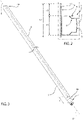
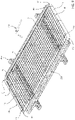
Figure 1 is a perspective view of a base bed for ship manufactured according to the principles of the present invention; -
Figure 2 is a side view, in section, of a part of the bed base for ship illustrated inFigure 1 ; -
Figures 3 to 9 illustrate as many operational steps of the method for manufacturing the bed base for ship illustrated inFigures 1 and2 . - With reference to
Figure 1 ,reference numeral 1 indicates, as a whole, a bed base for ship which is particularly suitable to be used inside boats such as cruise ships, military vessels or the like. - The bed base for
ship 1 comprises asupport frame 2 and asupport surface 3 designed to support a mattress (not illustrated). Thesupport frame 2 and thesupport surface 3 are made of metal material, for example steel or the like. Thesupport surface 3 is integral with the support frame. - According to a preferred embodiment shown in the accompanying figures, the
support frame 2 has the shape of a quadrilateral. In the illustrated example, thesupport frame 2 preferably has an approximately rectangular shape. Furthermore, it is understood that the present invention is not limited to arectangular support frame 2 but may envisage other shapes such as square, trapezoidal or the like. - According to a preferred exemplifying embodiment shown in
Figure 1 , the bed base forship 1 has a reference axis A and comprises a series of preferably rectilinear metal rods orbars 4 with a substantially rectangular section that are arranged transverse to the longitudinal axis A. - According to a preferred exemplifying embodiment shown in
Figure 1 , thesupport surface 3 comprises ametal bed base 5 which is fixed perimetrically to thesupport frame 2, preferably but not necessarily resting on theunderlying bars 4. - Preferably, the
bars 4 have the two opposite ends fixed at the head, for example by welding, to thesupport frame 2, preferably to the inner side walls of the two sides of thesupport frame 2 parallel to the longitudinal axis A, whereas themetal base bed 5 can be fixed perimetrically to thesupport frame 2, at least on two parallel and opposite sides of the same, for example by welding. - According to a preferred exemplifying embodiment shown in the accompanying figures, the
support frame 2 preferably comprises one or more tubular profiles 6 (cranes). The tubular profile(s) 6 extend along a longitudinal axis B and have a quadrangular, preferably rectangular section transverse to the same. - According to a preferred embodiment shown in
Figures 1 and2 , thesupport frame 2 comprises a singletubular profile 6 that preferably has four bends P1-P4. Preferably, the four bends P1-P4 are approximately right-angled (i.e. 90°) and are shaped so as to have a radius of curvature R2 at the relative vertices. The four bends P1-P4 are made at the respective four points of thetubular profile 6 that are intended to form the corners of thesupport frame 2. - In other words, the initially
rectilinear profile 6 is preferably shaped substantially in the shape of a rectangle and the two opposite end (or head) portions are arranged adjacent to and facing each other. In the illustrated example, thesupport frame 2 is preferably monolithic and is preferably made from a singletubular profile 6. - The radius of curvature R2 is preferably comprised between approximately 80 mm (millimetres) and approximately 100 mm, and more conveniently is equal to approximately 90 mm.
- In addition, in the preferred embodiment of the invention, an
end portion 6a of thetubular profile 6 with a pre-set length ℓ1 preferably has a narrowing/bottleneck 7. - The length ℓ1 is preferably comprised between approximately 40 mm and approximately 200 mm, and more conveniently is approximately equal to 70 mm.
- More specifically, the
end portion 6a is preferably subjected to a deformation process, such as for example a rolling or a pressing, which has the aim to locally reduce the transverse dimensions of theend portion 6a and obtain the narrowing 7 so that it is possible to insert/engage theend portion 6a inside the opposite and facingend portion 6b of thetubular profile 6 and form thesupport frame 2. - According to a preferred embodiment shown in
Figure 2 , thetubular profile 6 has a substantially rectangular, hollow cross-section preferably having at least one upper shoulder 8 which, in use, is designed to receive resting thesupport surface 3, so that thesupport surface 3 is positioned slightly recessed in and/or substantially flush with thesupport frame 2. - According to a preferred exemplifying embodiment shown in
Figure 2 , thetubular profile 6 has a height h1 that is preferably comprised between approximately 20 mm and approximately 60 mm, and more conveniently is equal to approximately 40 mm. - It is further understood that the
support frame 2 may have a shape different from a rectangular shape, such as for example square, trapezoidal or the like, and/or may comprise two or moretubular profiles 6. - In particular, in an alternative embodiment of the invention, the
support frame 2 may comprise a pair of C-shapedtubular profiles 6 mutually fixed to each other at the head or four L-shapedtubular profiles 6 and mutually fixed to each other at the head. - In addition, the bed base for
ship 1 is preferably provided with a plurality of legs/feet 9 for resting on the ground, which are firmly connected to thebars 4 and/or to thesupport frame 2. - According to the present invention, the bed base for
ship 1 further comprises a plate-shaped/band-shaped containment frame 10, which is integral with thesupport frame 2 and is dimensioned so as to conveniently carry out the function of mattress retainer. Preferably, thecontainment frame 10 is rigidly fixed, for example by welding, onto at least two outer sides of thesupport frame 2 and has at least a first bend K1-K4 with a first predetermined radius of curvature R1 at a relative corner of saidcontainment frame 10. - In the following disclosure, explicit reference will be made without thereby losing generality to a
containment frame 10 that is rigidly fixed, for example by welding, onto the four outer sides of thesupport frame 2. - According to a preferred exemplifying embodiment shown in
Figures 1 and2 , thecontainment frame 10 slightly exceeds the outer dimensions of the perimeter of thesupport frame 2. Thecontainment frame 10 is rigidly fixed to the outer side walls/sides of thesupport frame 2 so as to surround and laterally cover/coat the same. - The
containment frame 10 can conveniently have a height h2 comprised between approximately 50 mm and approximately 120 mm, preferably of approximately 70 mm. - According to a preferred exemplifying embodiment shown in
Figures 1 and2 , the upper annular edge of thecontainment frame 10 protrudes vertically in a cantilever fashion over thesupport frame 2 and/or over thesupport surface 3 by a predetermined height d1. - The height d1 can be comprised between approximately 10 mm and approximately 100 mm, and is preferably equal to approximately 25 mm.
- The
containment frame 10 has the technical effect of externally covering/masking thesupport frame 2 so as to improve the aesthetic appearance of the bed base forship 1. A further technical effect of thecontainment frame 10 is that of carrying out the function of locking and lateral containment of the mattress, replacing the traditional mattress retainer elements. In fact, thesupport frame 2 prevents the mattress from moving during the pitching and rolling movements of the boat. - With reference to
Figures 1 and2 , thecontainment frame 10 consists of one or more plate-shaped/band-shaped strips 11 made of metal material with a rectangular section of reduced thickness. - According to a preferred exemplifying embodiment shown in the accompanying figures, the
containment frame 10 is formed by four plate-shaped strips 11 rigidly fixed onto the outer side walls of thesupport frame 2, for example by welding. Thestrips 11 are substantially shaped in the shape of an L and have respective bends K1-K4, preferably right-angled, with a radius of curvature R1. - According to a preferred embodiment shown in the accompanying figures, the
strips 11 are rigidly fixed onto the outer side walls of thesupport frame 2 so that the relative bends K1-K4 overlap the respective bends P1-P4 of thetubular profile 6 forming thesupport frame 2. - According to a possible embodiment, the
strips 11 can conveniently be fixed rigidly, for example by welding, to each other at the head. - The radius of curvature R1 can be comprised between approximately 60 mm and approximately 100 mm, preferably is equal to approximately 80 mm.
- Preferably, the radius of curvature R1 of the bends K1-K4 can be smaller than the radius of curvature R2 of the bends P1-P4.
- According to a different embodiment, the
containment frame 10 can comprise asingle strip 11 provided with the four bends K1-K4 so as to be substantially shaped in the shape of a rectangle. - According to a further different embodiment, the
containment frame 10 can comprise a pair ofstrips 11, each of which is provided with two of the bends K1-K4 and is C-shaped. - With reference to
Figures 3 to 10, the method for manufacturing the bed base forship 1 having the above-described structure will be described in the following. - The method for manufacturing the bed base for
ship 1 object of the present invention essentially envisages the steps of: - pre-arranging one or more preferably rectilinear
tubular profiles 6 made of metal material that are intended to form thesupport frame 2; - making, on the tubular profile(s) 6, one or more bends P1-P4 with the radius of curvature R2 at the points of the tubular profile(s) 6 that are intended to form the corners of the
support frame 2; - pre-arranging one or more plate-shaped
strips 11 of an appropriate thickness made of metal material that are intended to form thecontainment frame 10; - making at least one bend K1-K4 with the radius of curvature R1 on the plate-shaped strip(s) 11; and
- applying the plate-shaped strip(s) 11 onto the outer side walls of the
support frame 2, so that the upper annular edge of thecontainment frame 10 protrudes in a cantilever fashion over thesupport frame 2 and/or thesupport surface 3. - In other words, the method for manufacturing the bed base for
ship 1 object of the present invention envisages fixing/positioning the plate-shaped strip(s) 11 on the lateral sides of thesupport frame 2, so that the upper annular edge of thecontainment frame 10 protrudes vertically in a cantilever fashion over the horizontal lying plane of thesupport frame 2. - With reference to
Figure 3 , the method for manufacturing the bed base forship 1 preferably envisages, prior to the step of making the bends P1-P4 on the tubular profile(s) 6, the step of making the narrowing/bottleneck 7 on theend portion 6a of thetubular profile 6. - In particular, in the preferred embodiment of the invention, the step of making the narrowing on the
end portion 6a of thetubular profile 6 preferably envisages the step of deforming, by rolling or pressing, theend portion 6a of thetubular profile 6 so as to locally compress/reduce the transverse dimensions of theend portion 6a. - With reference to
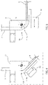
Figures 4 and 5 , the step of making the bends P1-P4 on the tubular profile(s) 6 preferably envisages the step of positioning the tubular profile(s) 6 by means of a preferably pneumatically operated bending machine (or pipe bending machine) 100 that is structured to make the bends P1-P4. - The bending
machine 100 can comprise, for example, a bending die 101 that has a curved lateral side that has a radius substantially equal to the radius of curvature R2; and a preferably pneumatically operated bendingmember 102 that is structured to rotate a portion of thetubular profile 6 at least by an angle substantially equal to 90° so as to make one of the bends P1-P4. - In the preferred embodiment of the invention, the method envisages pre-arranging preferably a single rectilinear
tubular profile 6 and making the four bends P1-P4 on the rectilineartubular profile 6 so as to shape thetubular profile 6 substantially in the shape of a rectangle. - With reference to the preferred embodiment of the invention illustrated in
Figure 6 , after making the bends P1-P4 on thetubular profile 6, the method further comprises the step of drawing closer and engaging the narrowingportion 6a inside the opposite and facingend portion 6b of the benttubular profile 6. The method further comprises the step of rigidly joining/fixing, for example by welding, the twoend portions tubular profile 6 engaged with each other so as to obtain thesupport frame 2. - With reference to
Figures 7 and 8 , the method further comprises the step of pre-arranging four plate-shapedstrips 11 that are intended to form thecontainment frame 10. - The method further comprises the step of making the right-angled bends K1-K4 with the radius of curvature R1 on the plate-shaped
strips 11 so as to shape eachstrip 11 substantially in the shape of an L. - In the illustrated example, the step of making the bends K1-K4 on the plate-shaped
strips 11 preferably envisages the step of positioning thestrips 11 on a preferably pneumatically or electrically operated bendingmachine 200 and making the bends K1-K4 on the plate-shapedstrips 11 by means of the same. - According to a possible embodiment, the bending
machine 200 can be provided with: a bendingroller 201 and at least one bendingmember 202. The bendingroller 201 can have a radius substantially equal to the radius of curvature R1. The bendingmember 202 can be pneumatically or electrically operated and be structured to rotate a portion of the plate-shapedstrip 11 by an angle substantially equal to 90° so as to make the right-angled bends K1-K4. - With reference to Figure 10, the method for manufacturing the bed base for
ship 1 preferably envisages, after bending the plate-shaped strip (s) 11, the step of rigidly fixing, for example by welding, the plate-shaped strip(s) 11 onto the lateral sides of thesupport frame 2 so as to obtain thecontainment frame 10. - More specifically, the step of rigidly fixing the plate-shaped strip(s) 11 onto the lateral sides of the
support frame 2 preferably envisages the steps of: - pre-arranging a moulder (or template)
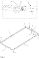
frame 300 that is provided with at least a plurality of first locking members (not visible in the figures) designed to firmly hold thesupport frame 2 and a plurality of second locking (or clamping)members 301 designed to firmly hold thestrips 11 in a pre-set position in abutment against the outer side walls of thesupport frame 2, or more precisely of thetubular profile 6; - arranging and rigidly locking the
support frame 2 or, more precisely, the previously benttubular profile 6, on themoulder frame 300; - arranging and locking the
strips 11 in the pre-set position in abutment against the outer side walls of the support frame, or more precisely of thetubular profile 6; - rigidly fixing, for example by welding, the plate-formed
strips 11 onto thesupport frame 2 so as to obtain thecontainment frame 10. - In addition, the
moulder frame 300 preferably also comprises: an electrically or pneumatically operated welding assembly 302 (only partially illustrated inFigure 9 ); and an electronic control apparatus (not visible in the figures) that is designed to control/drive thewelding assembly 302 based on pre-set algorithms and/or based on electrical detection signals from a plurality of sensors positioned/distributed over thewelding assembly 302 so as to perform the pre-set welds on the bed base forship 1. - The technical effects obtained thanks to the use of a
moulder frame 300 specifically structured to receive and rigidly lock thesupport frame 2 and the strip (s) 11 are those of: ensuring the correct positioning/support of the L-shaped strip(s) 11 on the outer side walls of thesupport frame 2, or more precisely of thetubular profile 6; and allowing compensating any manufacturing tolerances of the bends P1-P4 of thesupport frame 2, or more precisely of thetubular profile 6. - More specifically, it can occur that the actual radius of curvature of the bends P1-P4 of the
support frame 2 deviates from the nominal dimensions, i.e. it is smaller or greater than the radius of curvature R2. - The positioning of the
strips 11 by means of themoulder frame 300 allows arranging thestrips 11 with extreme precision in abutment against the outer side walls of thesupport frame 2, or more precisely of thetubular profile 6, potentially also slightly deforming thestrips 11 so as to compensate any manufacturing tolerances of the bends P1-P4 of thesupport frame 2, or more precisely of thetubular profile 6. - More specifically, the moulder frame allows pressing the
strips 11 with force against the outer side walls of thesupport frame 2 so that thestrips 11 correctly adhere to the outer side walls of thesupport frame 2, and further have the heads respectively in abutment against each other. - This way, the welding of the
strips 11 onto the outer side walls of thesupport frame 2 is considerably simpler and more precise, and allows obtaining acontainment frame 10 with a regular and homogeneous outer surface, lacking discontinuities between thestrips 11. - With reference to the preferred embodiment of the invention illustrated in
Figure 9 , the method preferably envisages the step of positioning the four L-shaped plate-shapedstrips 11 in abutment against the side walls of thesupport frame 2 so that each bend K1-K4 of thestrips 11 substantially overlaps a respective bend P1-P4 of thesupport frame 2, or more precisely of thetubular profile 6. - In addition, the method preferably envisages the step of firmly holding each
strip 11 in the pre-set position by means of the lockingmembers 301 of themoulder frame 300. - With reference to
Figure 9 , the method preferably envisages the step of rigidly fixing the four plate-shapedstrips 11 onto the side walls of thesupport frame 2, or more precisely of thetubular profile 6, for example by welding. In the illustrated example, the method further preferably envisages the step of rigidly fixing the plate-shapedstrips 11 to each other, for example by welding thestrips 11 to each other at the head. - The advantages associated with the introduction of the above-described method for manufacturing the bed base for
ship 1 are considerable. - Firstly, the bed base for
ship 1, thanks to the presence of thecontainment frame 10, is able to firmly hold the mattress positioned on thesupport surface 3 so as to prevent the mattress from making undesired movements during the rolling and pitching movements of the boat. - In addition, the pre-arrangement of the
moulder frame 300 allows the L-shapedstrips 11 to correctly adhere to the outer side walls of thesupport frame 2 and allows compensating any manufacturing tolerances of the bends P1-P4 of thesupport frame 2, or more precisely of thetubular profile 6, so as to obtain acontainment frame 10 with a homogeneous and regular outer surface, i.e. lacking discontinuities between thestrips 11. - Finally, it is evident that modifications and variants can be made to the support frame and to the method for manufacturing the support frame described and illustrated in the foregoing without thereby departing from the scope of protection of the present invention.
Claims (14)
- A bed base for ship (1) made of metal material comprising:- a support frame (2) that lies on a reference plane,- a support surface (3) that is coupled to said support frame (2) so as to be parallel to said reference plane and is structured to support at least one mattress,- an outer plate-shaped containment frame (10) that is firmly coupled onto the outer side walls of the support frame (2) so as to surround the latter on at least two sides,said outer plate-shaped containment frame (10) is arranged approximately orthogonal to said reference plane and has at least a first bend (K1-K4) having a first prefixed radius of curvature (R1) at a relative corner of said support frame (2).
- The bed base for ship according to claim 1, wherein said outer plate-shaped containment frame (10) has an annular upper containment portion that protrudes in a cantilever fashion over said support frame (2) and/or over said support surface (3) and is designed to surround and at least partially contain said mattress in order to prevent it from moving on said support surface (3).
- The bed base for ship according to claim 2, wherein said outer plate-shaped containment frame (10) consists of one or more plate-shaped strips (11) made of metal material that have one or more first bends (K1-K4) having said first pre-set radius of curvature (R1) at respective corners of said containment frame (10).
- The bed base for ship according to claim 2 or 3, wherein said support frame (2) and said outer plate-shaped containment frame (10) have an approximately rectangular shape; said outer plate-shaped containment frame (10) comprises four plate-shaped strips (11) made of metal material shaped so as to have said first bends (K1-K4) that have said first pre-set radius of curvature (R1) and are made at the respective four corners of said outer plate-shaped containment frame (10).
- The bed base for ship according to any one of the preceding claims, wherein said strips (11) are welded onto the outer sides of said support frame (2).
- The bed base for ship according to any one of the claims 2 to 5, wherein said annular upper portion protrudes in a cantilever fashion in a substantially vertical direction over said support frame (2) and/or over said support surface (3) by a pre-set height (di) comprised between approximately 10mm and approximately 100mm.
- A method for manufacturing a bed base for ship (1) made of metal material as defined in any one of the preceding claims comprising the steps of:- pre-arranging a support frame (2) that lies on a reference plane,- firmly coupling a support surface (3), that is structured to support at least one mattress, to said support frame (2) so as to be parallel to said reference plane,- coupling said plate-shaped strips (11) made of metal material onto the outer side walls of the support frame (2) so as to surround the latter on at least two sides in order to form said outer plate-shaped containment frame (10).
- The method according to claim 7 comprising the step of coupling said plate-shaped strips (11) made of metal material onto the outer side walls of the support frame (2) in order to form an outer plate-shaped containment frame (10) that has an annular upper containment portion that protrudes in a cantilever fashion over said support frame (2) and/or over said support surface (3) and is designed to surround and at least partially contain said mattress in order to prevent it from moving on said support surface (3).
- The method according to claim 8, wherein said annular upper portion protrudes in a cantilever fashion in a substantially vertical direction over said support frame (2) and/or said support surface (3) by a pre-set height (di) comprised between approximately 10mm and approximately 100mm.
- The method according to claims 8 or 9, comprising the step of bending said plate-shaped strips (11) made of metal material thus forming a plurality of first bends (K1-K4) with a first pre-set radius of curvature (R1) at the corners of said outer plate-shaped containment frame (10).
- The method according to claim 10, wherein said support frame (2) and said outer plate-shaped containment frame (10) have an approximately rectangular shape,
said method comprising the step of prearranging four strips (11), making on the four strips respective said first bends (K1-K4) according to said first radius of curvature (R1) wherein each first bend is made at a relative corner of said outer plate-shaped containment frame (10). - The method according to any one of the claims 7 to 11 comprising the steps of:- pre-arranging at least one rectilinear tubular profile (6) made of metal material,- making, on said tubular profile (6), a series of second bends (P1-P4) having a second radius of curvature (R2) in order to form said support frame (2),- making, on said strips (11), relative said first bends (K1-K4) having said first radius of curvature (R1),- fixing said bent strips (11) onto the outer side walls of the tubular profile (6) of said support frame (2) so that said second bends (P1-P4) are arranged on the respective first bends (K1-K4) .
- The method according to claim 12, wherein said first radius of curvature (R1) is equal to approximately 80mm and/or said second radius of curvature (R2) is equal to approximately 90mm and/or said first radius of curvature (R1) is less than said second radius of curvature (R2).
- The method according to any one of the claims 7 to 13, comprising the steps of:- pre-arranging a moulder frame (300) that is provided with at least a plurality of first locking members and with a plurality of second locking members (301);- arranging said support frame (2) on said moulder frame (300),- actuating said first locking members in order to firmly hold said support frame (2) on said moulder frame (300)- arranging said plate-shaped strips (11) in a predetermined position in abutment against the outer side walls of said support frame (2),- actuating said second locking members (301) in order to firmly hold said plate-shaped strips (11) in a predetermined position in abutment against the outer side walls of said support frame (2),- rigidly fixing said strips (11) onto said support frame (2), in order to obtain said containment frame (10).
Applications Claiming Priority (1)
| Application Number | Priority Date | Filing Date | Title |
|---|---|---|---|
| IT102020000028511A IT202000028511A1 (en) | 2020-11-26 | 2020-11-26 | NAVAL NETWORK AND RELATED METHOD OF REALIZATION |
Publications (2)
| Publication Number | Publication Date |
|---|---|
| EP4005915A1 true EP4005915A1 (en) | 2022-06-01 |
| EP4005915B1 EP4005915B1 (en) | 2024-04-10 |
Family
ID=74557180
Family Applications (1)
| Application Number | Title | Priority Date | Filing Date |
|---|---|---|---|
| EP21210868.2A Active EP4005915B1 (en) | 2020-11-26 | 2021-11-26 | Bed base for ship and relative manufacturing method |
Country Status (2)
| Country | Link |
|---|---|
| EP (1) | EP4005915B1 (en) |
| IT (1) | IT202000028511A1 (en) |
Cited By (1)
| Publication number | Priority date | Publication date | Assignee | Title |
|---|---|---|---|---|
| CN115625493A (en) * | 2022-11-18 | 2023-01-20 | 南通德玛瑞机械制造有限公司 | Machining process of marine base |
Citations (3)
| Publication number | Priority date | Publication date | Assignee | Title |
|---|---|---|---|---|
| US1218868A (en) * | 1915-06-04 | 1917-03-13 | Benjamin H Jones | Folding cot-bed. |
| SE407332B (en) * | 1977-02-10 | 1979-03-26 | Tornborgs Maskinfabrik Ab | KIT TO MANUFACTURE A FURNITURE WITH A FRAME OF PLATE AND HALF PROFILE ELEMENT FOR PERFORMANCE OF THE KIT |
| FR2517947A1 (en) * | 1981-12-10 | 1983-06-17 | Rey Henri | Convertible camp bed and chair - has hinged frame, with mattress base joined to it by springs, with legs |
-
2020
- 2020-11-26 IT IT102020000028511A patent/IT202000028511A1/en unknown
-
2021
- 2021-11-26 EP EP21210868.2A patent/EP4005915B1/en active Active
Patent Citations (3)
| Publication number | Priority date | Publication date | Assignee | Title |
|---|---|---|---|---|
| US1218868A (en) * | 1915-06-04 | 1917-03-13 | Benjamin H Jones | Folding cot-bed. |
| SE407332B (en) * | 1977-02-10 | 1979-03-26 | Tornborgs Maskinfabrik Ab | KIT TO MANUFACTURE A FURNITURE WITH A FRAME OF PLATE AND HALF PROFILE ELEMENT FOR PERFORMANCE OF THE KIT |
| FR2517947A1 (en) * | 1981-12-10 | 1983-06-17 | Rey Henri | Convertible camp bed and chair - has hinged frame, with mattress base joined to it by springs, with legs |
Cited By (1)
| Publication number | Priority date | Publication date | Assignee | Title |
|---|---|---|---|---|
| CN115625493A (en) * | 2022-11-18 | 2023-01-20 | 南通德玛瑞机械制造有限公司 | Machining process of marine base |
Also Published As
| Publication number | Publication date |
|---|---|
| IT202000028511A1 (en) | 2022-05-26 |
| EP4005915B1 (en) | 2024-04-10 |
Similar Documents
| Publication | Publication Date | Title |
|---|---|---|
| EP4005915B1 (en) | Bed base for ship and relative manufacturing method | |
| RS61365B1 (en) | PROFILES | |
| US20190176204A1 (en) | Pressed component manufacturing method, press, and press line | |
| CN102085542A (en) | Techniques for designing and manufacturing precision-folded, high strength, fatigue-resistant structures and sheet therefor | |
| US11530735B2 (en) | Rigid chain link and rigid chain equipped with such a link | |
| US20200078843A1 (en) | Systems and methods for manufacturing a ring from a metal sheet | |
| JP5913294B2 (en) | Manufacturing method of hollow profile | |
| US11986873B2 (en) | Connecting sheet metal end sections by means of forming | |
| EP2546424B1 (en) | Angle bracket for fastening a first construction element to a second construction element and method for producing an angle bracket | |
| US20090320548A1 (en) | Apparatus and methods for material fabrication | |
| US3765211A (en) | Tank liner with curved flanges, apparatus and method for making same | |
| AU2017101839A4 (en) | Apparatus and tool for bending contoured metal sheeting about a fold line | |
| CN116551326B (en) | Preparation method of roll-formed frame and roll-formed frame | |
| US6988390B2 (en) | Method and installation for making a workpiece comprising at least a tubular section | |
| JP2003290918A (en) | Welded wide flange shape, and method for manufacturing the same | |
| JPH02127388A (en) | Main frame structure of passenger conveyor | |
| US3874545A (en) | Cryogenic tank and tank liner with curved flanges | |
| JP5993556B2 (en) | Corner structure of formwork panel and concrete formwork construction method | |
| JP5286506B2 (en) | Pipe bending machine | |
| RU2198757C2 (en) | Walls | |
| JP3319828B2 (en) | Bending method of high-rigid structure provided with reinforcing ribs and molding die | |
| JP2009184402A (en) | Mounting structure for vehicle interior materials | |
| KR101737487B1 (en) | Apparatus for building processing panel and methode for processing thereof | |
| US8136464B1 (en) | C-fast system | |
| CN120838933B (en) | A method, apparatus, and storage medium for bending non-standard frames. |
Legal Events
| Date | Code | Title | Description |
|---|---|---|---|
| PUAI | Public reference made under article 153(3) epc to a published international application that has entered the european phase |
Free format text: ORIGINAL CODE: 0009012 |
|
| STAA | Information on the status of an ep patent application or granted ep patent |
Free format text: STATUS: THE APPLICATION HAS BEEN PUBLISHED |
|
| AK | Designated contracting states |
Kind code of ref document: A1 Designated state(s): AL AT BE BG CH CY CZ DE DK EE ES FI FR GB GR HR HU IE IS IT LI LT LU LV MC MK MT NL NO PL PT RO RS SE SI SK SM TR |
|
| STAA | Information on the status of an ep patent application or granted ep patent |
Free format text: STATUS: REQUEST FOR EXAMINATION WAS MADE |
|
| 17P | Request for examination filed |
Effective date: 20221130 |
|
| RBV | Designated contracting states (corrected) |
Designated state(s): AL AT BE BG CH CY CZ DE DK EE ES FI FR GB GR HR HU IE IS IT LI LT LU LV MC MK MT NL NO PL PT RO RS SE SI SK SM TR |
|
| GRAP | Despatch of communication of intention to grant a patent |
Free format text: ORIGINAL CODE: EPIDOSNIGR1 |
|
| STAA | Information on the status of an ep patent application or granted ep patent |
Free format text: STATUS: GRANT OF PATENT IS INTENDED |
|
| RIC1 | Information provided on ipc code assigned before grant |
Ipc: B63B 29/10 20060101AFI20231012BHEP |
|
| INTG | Intention to grant announced |
Effective date: 20231106 |
|
| GRAS | Grant fee paid |
Free format text: ORIGINAL CODE: EPIDOSNIGR3 |
|
| GRAA | (expected) grant |
Free format text: ORIGINAL CODE: 0009210 |
|
| STAA | Information on the status of an ep patent application or granted ep patent |
Free format text: STATUS: THE PATENT HAS BEEN GRANTED |
|
| P01 | Opt-out of the competence of the unified patent court (upc) registered |
Effective date: 20240220 |
|
| AK | Designated contracting states |
Kind code of ref document: B1 Designated state(s): AL AT BE BG CH CY CZ DE DK EE ES FI FR GB GR HR HU IE IS IT LI LT LU LV MC MK MT NL NO PL PT RO RS SE SI SK SM TR |
|
| REG | Reference to a national code |
Ref country code: GB Ref legal event code: FG4D |
|
| REG | Reference to a national code |
Ref country code: CH Ref legal event code: EP |
|
| REG | Reference to a national code |
Ref country code: DE Ref legal event code: R096 Ref document number: 602021011586 Country of ref document: DE |
|
| REG | Reference to a national code |
Ref country code: IE Ref legal event code: FG4D |
|
| REG | Reference to a national code |
Ref country code: LT Ref legal event code: MG9D |
|
| REG | Reference to a national code |
Ref country code: NL Ref legal event code: MP Effective date: 20240410 |
|
| REG | Reference to a national code |
Ref country code: AT Ref legal event code: MK05 Ref document number: 1674667 Country of ref document: AT Kind code of ref document: T Effective date: 20240410 |
|
| PG25 | Lapsed in a contracting state [announced via postgrant information from national office to epo] |
Ref country code: NL Free format text: LAPSE BECAUSE OF FAILURE TO SUBMIT A TRANSLATION OF THE DESCRIPTION OR TO PAY THE FEE WITHIN THE PRESCRIBED TIME-LIMIT Effective date: 20240410 |
|
| PG25 | Lapsed in a contracting state [announced via postgrant information from national office to epo] |
Ref country code: NL Free format text: LAPSE BECAUSE OF FAILURE TO SUBMIT A TRANSLATION OF THE DESCRIPTION OR TO PAY THE FEE WITHIN THE PRESCRIBED TIME-LIMIT Effective date: 20240410 |
|
| PG25 | Lapsed in a contracting state [announced via postgrant information from national office to epo] |
Ref country code: IS Free format text: LAPSE BECAUSE OF FAILURE TO SUBMIT A TRANSLATION OF THE DESCRIPTION OR TO PAY THE FEE WITHIN THE PRESCRIBED TIME-LIMIT Effective date: 20240810 |
|
| PG25 | Lapsed in a contracting state [announced via postgrant information from national office to epo] |
Ref country code: BG Free format text: LAPSE BECAUSE OF FAILURE TO SUBMIT A TRANSLATION OF THE DESCRIPTION OR TO PAY THE FEE WITHIN THE PRESCRIBED TIME-LIMIT Effective date: 20240410 |
|
| PG25 | Lapsed in a contracting state [announced via postgrant information from national office to epo] |
Ref country code: FI Free format text: LAPSE BECAUSE OF FAILURE TO SUBMIT A TRANSLATION OF THE DESCRIPTION OR TO PAY THE FEE WITHIN THE PRESCRIBED TIME-LIMIT Effective date: 20240410 Ref country code: HR Free format text: LAPSE BECAUSE OF FAILURE TO SUBMIT A TRANSLATION OF THE DESCRIPTION OR TO PAY THE FEE WITHIN THE PRESCRIBED TIME-LIMIT Effective date: 20240410 |
|
| PG25 | Lapsed in a contracting state [announced via postgrant information from national office to epo] |
Ref country code: GR Free format text: LAPSE BECAUSE OF FAILURE TO SUBMIT A TRANSLATION OF THE DESCRIPTION OR TO PAY THE FEE WITHIN THE PRESCRIBED TIME-LIMIT Effective date: 20240711 |
|
| PG25 | Lapsed in a contracting state [announced via postgrant information from national office to epo] |
Ref country code: PT Free format text: LAPSE BECAUSE OF FAILURE TO SUBMIT A TRANSLATION OF THE DESCRIPTION OR TO PAY THE FEE WITHIN THE PRESCRIBED TIME-LIMIT Effective date: 20240812 |
|
| PG25 | Lapsed in a contracting state [announced via postgrant information from national office to epo] |
Ref country code: ES Free format text: LAPSE BECAUSE OF FAILURE TO SUBMIT A TRANSLATION OF THE DESCRIPTION OR TO PAY THE FEE WITHIN THE PRESCRIBED TIME-LIMIT Effective date: 20240410 |
|
| PG25 | Lapsed in a contracting state [announced via postgrant information from national office to epo] |
Ref country code: AT Free format text: LAPSE BECAUSE OF FAILURE TO SUBMIT A TRANSLATION OF THE DESCRIPTION OR TO PAY THE FEE WITHIN THE PRESCRIBED TIME-LIMIT Effective date: 20240410 |
|
| PG25 | Lapsed in a contracting state [announced via postgrant information from national office to epo] |
Ref country code: PL Free format text: LAPSE BECAUSE OF FAILURE TO SUBMIT A TRANSLATION OF THE DESCRIPTION OR TO PAY THE FEE WITHIN THE PRESCRIBED TIME-LIMIT Effective date: 20240410 |
|
| PG25 | Lapsed in a contracting state [announced via postgrant information from national office to epo] |
Ref country code: LV Free format text: LAPSE BECAUSE OF FAILURE TO SUBMIT A TRANSLATION OF THE DESCRIPTION OR TO PAY THE FEE WITHIN THE PRESCRIBED TIME-LIMIT Effective date: 20240410 |
|
| PG25 | Lapsed in a contracting state [announced via postgrant information from national office to epo] |
Ref country code: PT Free format text: LAPSE BECAUSE OF FAILURE TO SUBMIT A TRANSLATION OF THE DESCRIPTION OR TO PAY THE FEE WITHIN THE PRESCRIBED TIME-LIMIT Effective date: 20240812 Ref country code: PL Free format text: LAPSE BECAUSE OF FAILURE TO SUBMIT A TRANSLATION OF THE DESCRIPTION OR TO PAY THE FEE WITHIN THE PRESCRIBED TIME-LIMIT Effective date: 20240410 Ref country code: NO Free format text: LAPSE BECAUSE OF FAILURE TO SUBMIT A TRANSLATION OF THE DESCRIPTION OR TO PAY THE FEE WITHIN THE PRESCRIBED TIME-LIMIT Effective date: 20240710 Ref country code: LV Free format text: LAPSE BECAUSE OF FAILURE TO SUBMIT A TRANSLATION OF THE DESCRIPTION OR TO PAY THE FEE WITHIN THE PRESCRIBED TIME-LIMIT Effective date: 20240410 Ref country code: IS Free format text: LAPSE BECAUSE OF FAILURE TO SUBMIT A TRANSLATION OF THE DESCRIPTION OR TO PAY THE FEE WITHIN THE PRESCRIBED TIME-LIMIT Effective date: 20240810 Ref country code: HR Free format text: LAPSE BECAUSE OF FAILURE TO SUBMIT A TRANSLATION OF THE DESCRIPTION OR TO PAY THE FEE WITHIN THE PRESCRIBED TIME-LIMIT Effective date: 20240410 Ref country code: GR Free format text: LAPSE BECAUSE OF FAILURE TO SUBMIT A TRANSLATION OF THE DESCRIPTION OR TO PAY THE FEE WITHIN THE PRESCRIBED TIME-LIMIT Effective date: 20240711 Ref country code: FI Free format text: LAPSE BECAUSE OF FAILURE TO SUBMIT A TRANSLATION OF THE DESCRIPTION OR TO PAY THE FEE WITHIN THE PRESCRIBED TIME-LIMIT Effective date: 20240410 Ref country code: ES Free format text: LAPSE BECAUSE OF FAILURE TO SUBMIT A TRANSLATION OF THE DESCRIPTION OR TO PAY THE FEE WITHIN THE PRESCRIBED TIME-LIMIT Effective date: 20240410 Ref country code: BG Free format text: LAPSE BECAUSE OF FAILURE TO SUBMIT A TRANSLATION OF THE DESCRIPTION OR TO PAY THE FEE WITHIN THE PRESCRIBED TIME-LIMIT Effective date: 20240410 Ref country code: AT Free format text: LAPSE BECAUSE OF FAILURE TO SUBMIT A TRANSLATION OF THE DESCRIPTION OR TO PAY THE FEE WITHIN THE PRESCRIBED TIME-LIMIT Effective date: 20240410 Ref country code: RS Free format text: LAPSE BECAUSE OF FAILURE TO SUBMIT A TRANSLATION OF THE DESCRIPTION OR TO PAY THE FEE WITHIN THE PRESCRIBED TIME-LIMIT Effective date: 20240710 |
|
| REG | Reference to a national code |
Ref country code: DE Ref legal event code: R097 Ref document number: 602021011586 Country of ref document: DE |
|
| PG25 | Lapsed in a contracting state [announced via postgrant information from national office to epo] |
Ref country code: DK Free format text: LAPSE BECAUSE OF FAILURE TO SUBMIT A TRANSLATION OF THE DESCRIPTION OR TO PAY THE FEE WITHIN THE PRESCRIBED TIME-LIMIT Effective date: 20240410 |
|
| PG25 | Lapsed in a contracting state [announced via postgrant information from national office to epo] |
Ref country code: EE Free format text: LAPSE BECAUSE OF FAILURE TO SUBMIT A TRANSLATION OF THE DESCRIPTION OR TO PAY THE FEE WITHIN THE PRESCRIBED TIME-LIMIT Effective date: 20240410 |
|
| PG25 | Lapsed in a contracting state [announced via postgrant information from national office to epo] |
Ref country code: CZ Free format text: LAPSE BECAUSE OF FAILURE TO SUBMIT A TRANSLATION OF THE DESCRIPTION OR TO PAY THE FEE WITHIN THE PRESCRIBED TIME-LIMIT Effective date: 20240410 |
|
| PG25 | Lapsed in a contracting state [announced via postgrant information from national office to epo] |
Ref country code: RO Free format text: LAPSE BECAUSE OF FAILURE TO SUBMIT A TRANSLATION OF THE DESCRIPTION OR TO PAY THE FEE WITHIN THE PRESCRIBED TIME-LIMIT Effective date: 20240410 Ref country code: SK Free format text: LAPSE BECAUSE OF FAILURE TO SUBMIT A TRANSLATION OF THE DESCRIPTION OR TO PAY THE FEE WITHIN THE PRESCRIBED TIME-LIMIT Effective date: 20240410 |
|
| PG25 | Lapsed in a contracting state [announced via postgrant information from national office to epo] |
Ref country code: SM Free format text: LAPSE BECAUSE OF FAILURE TO SUBMIT A TRANSLATION OF THE DESCRIPTION OR TO PAY THE FEE WITHIN THE PRESCRIBED TIME-LIMIT Effective date: 20240410 |
|
| PG25 | Lapsed in a contracting state [announced via postgrant information from national office to epo] |
Ref country code: SM Free format text: LAPSE BECAUSE OF FAILURE TO SUBMIT A TRANSLATION OF THE DESCRIPTION OR TO PAY THE FEE WITHIN THE PRESCRIBED TIME-LIMIT Effective date: 20240410 Ref country code: SK Free format text: LAPSE BECAUSE OF FAILURE TO SUBMIT A TRANSLATION OF THE DESCRIPTION OR TO PAY THE FEE WITHIN THE PRESCRIBED TIME-LIMIT Effective date: 20240410 Ref country code: RO Free format text: LAPSE BECAUSE OF FAILURE TO SUBMIT A TRANSLATION OF THE DESCRIPTION OR TO PAY THE FEE WITHIN THE PRESCRIBED TIME-LIMIT Effective date: 20240410 Ref country code: EE Free format text: LAPSE BECAUSE OF FAILURE TO SUBMIT A TRANSLATION OF THE DESCRIPTION OR TO PAY THE FEE WITHIN THE PRESCRIBED TIME-LIMIT Effective date: 20240410 Ref country code: DK Free format text: LAPSE BECAUSE OF FAILURE TO SUBMIT A TRANSLATION OF THE DESCRIPTION OR TO PAY THE FEE WITHIN THE PRESCRIBED TIME-LIMIT Effective date: 20240410 Ref country code: CZ Free format text: LAPSE BECAUSE OF FAILURE TO SUBMIT A TRANSLATION OF THE DESCRIPTION OR TO PAY THE FEE WITHIN THE PRESCRIBED TIME-LIMIT Effective date: 20240410 |
|
| PG25 | Lapsed in a contracting state [announced via postgrant information from national office to epo] |
Ref country code: IT Free format text: LAPSE BECAUSE OF FAILURE TO SUBMIT A TRANSLATION OF THE DESCRIPTION OR TO PAY THE FEE WITHIN THE PRESCRIBED TIME-LIMIT Effective date: 20240410 |
|
| PLBE | No opposition filed within time limit |
Free format text: ORIGINAL CODE: 0009261 |
|
| STAA | Information on the status of an ep patent application or granted ep patent |
Free format text: STATUS: NO OPPOSITION FILED WITHIN TIME LIMIT |
|
| 26N | No opposition filed |
Effective date: 20250113 |
|
| PG25 | Lapsed in a contracting state [announced via postgrant information from national office to epo] |
Ref country code: SI Free format text: LAPSE BECAUSE OF FAILURE TO SUBMIT A TRANSLATION OF THE DESCRIPTION OR TO PAY THE FEE WITHIN THE PRESCRIBED TIME-LIMIT Effective date: 20240410 |
|
| REG | Reference to a national code |
Ref country code: CH Ref legal event code: PL |
|
| PG25 | Lapsed in a contracting state [announced via postgrant information from national office to epo] |
Ref country code: MC Free format text: LAPSE BECAUSE OF FAILURE TO SUBMIT A TRANSLATION OF THE DESCRIPTION OR TO PAY THE FEE WITHIN THE PRESCRIBED TIME-LIMIT Effective date: 20240410 |
|
| PG25 | Lapsed in a contracting state [announced via postgrant information from national office to epo] |
Ref country code: LU Free format text: LAPSE BECAUSE OF NON-PAYMENT OF DUE FEES Effective date: 20241126 |
|
| REG | Reference to a national code |
Ref country code: CH Ref legal event code: PL |
|
| PG25 | Lapsed in a contracting state [announced via postgrant information from national office to epo] |
Ref country code: CH Free format text: LAPSE BECAUSE OF NON-PAYMENT OF DUE FEES Effective date: 20241130 |
|
| REG | Reference to a national code |
Ref country code: BE Ref legal event code: MM Effective date: 20241130 |
|
| PG25 | Lapsed in a contracting state [announced via postgrant information from national office to epo] |
Ref country code: SE Free format text: LAPSE BECAUSE OF FAILURE TO SUBMIT A TRANSLATION OF THE DESCRIPTION OR TO PAY THE FEE WITHIN THE PRESCRIBED TIME-LIMIT Effective date: 20240410 |
|
| PG25 | Lapsed in a contracting state [announced via postgrant information from national office to epo] |
Ref country code: BE Free format text: LAPSE BECAUSE OF NON-PAYMENT OF DUE FEES Effective date: 20241130 |
|
| PG25 | Lapsed in a contracting state [announced via postgrant information from national office to epo] |
Ref country code: CH Free format text: LAPSE BECAUSE OF NON-PAYMENT OF DUE FEES Effective date: 20241130 |
|
| PGRI | Patent reinstated in contracting state [announced from national office to epo] |
Ref country code: CH Effective date: 20250728 |
|
| PG25 | Lapsed in a contracting state [announced via postgrant information from national office to epo] |
Ref country code: IE Free format text: LAPSE BECAUSE OF NON-PAYMENT OF DUE FEES Effective date: 20241126 |
|
| REG | Reference to a national code |
Ref country code: CH Ref legal event code: U11 Free format text: ST27 STATUS EVENT CODE: U-0-0-U10-U11 (AS PROVIDED BY THE NATIONAL OFFICE) Effective date: 20251201 |
|
| PGFP | Annual fee paid to national office [announced via postgrant information from national office to epo] |
Ref country code: DE Payment date: 20251126 Year of fee payment: 5 |
|
| PGFP | Annual fee paid to national office [announced via postgrant information from national office to epo] |
Ref country code: GB Payment date: 20251125 Year of fee payment: 5 |
|
| PGFP | Annual fee paid to national office [announced via postgrant information from national office to epo] |
Ref country code: FR Payment date: 20251124 Year of fee payment: 5 |
|
| PGFP | Annual fee paid to national office [announced via postgrant information from national office to epo] |
Ref country code: CH Payment date: 20251201 Year of fee payment: 5 |
|
| PG25 | Lapsed in a contracting state [announced via postgrant information from national office to epo] |
Ref country code: HU Free format text: LAPSE BECAUSE OF FAILURE TO SUBMIT A TRANSLATION OF THE DESCRIPTION OR TO PAY THE FEE WITHIN THE PRESCRIBED TIME-LIMIT; INVALID AB INITIO Effective date: 20211126 |
|
| PG25 | Lapsed in a contracting state [announced via postgrant information from national office to epo] |
Ref country code: CY Free format text: LAPSE BECAUSE OF FAILURE TO SUBMIT A TRANSLATION OF THE DESCRIPTION OR TO PAY THE FEE WITHIN THE PRESCRIBED TIME-LIMIT; INVALID AB INITIO Effective date: 20211126 |