EP4005846A1 - Powertrain and all-terrain vehicle - Google Patents
Powertrain and all-terrain vehicle Download PDFInfo
- Publication number
- EP4005846A1 EP4005846A1 EP21210494.7A EP21210494A EP4005846A1 EP 4005846 A1 EP4005846 A1 EP 4005846A1 EP 21210494 A EP21210494 A EP 21210494A EP 4005846 A1 EP4005846 A1 EP 4005846A1
- Authority
- EP
- European Patent Office
- Prior art keywords
- shaft
- power output
- output shaft
- casing
- axis
- Prior art date
- Legal status (The legal status is an assumption and is not a legal conclusion. Google has not performed a legal analysis and makes no representation as to the accuracy of the status listed.)
- Pending
Links
Images



Classifications
-
- F—MECHANICAL ENGINEERING; LIGHTING; HEATING; WEAPONS; BLASTING
- F16—ENGINEERING ELEMENTS AND UNITS; GENERAL MEASURES FOR PRODUCING AND MAINTAINING EFFECTIVE FUNCTIONING OF MACHINES OR INSTALLATIONS; THERMAL INSULATION IN GENERAL
- F16H—GEARING
- F16H1/00—Toothed gearings for conveying rotary motion
- F16H1/02—Toothed gearings for conveying rotary motion without gears having orbital motion
- F16H1/20—Toothed gearings for conveying rotary motion without gears having orbital motion involving more than two intermeshing members
- F16H1/22—Toothed gearings for conveying rotary motion without gears having orbital motion involving more than two intermeshing members with a plurality of driving or driven shafts; with arrangements for dividing torque between two or more intermediate shafts
- F16H1/222—Toothed gearings for conveying rotary motion without gears having orbital motion involving more than two intermeshing members with a plurality of driving or driven shafts; with arrangements for dividing torque between two or more intermediate shafts with non-parallel axes
-
- F—MECHANICAL ENGINEERING; LIGHTING; HEATING; WEAPONS; BLASTING
- F16—ENGINEERING ELEMENTS AND UNITS; GENERAL MEASURES FOR PRODUCING AND MAINTAINING EFFECTIVE FUNCTIONING OF MACHINES OR INSTALLATIONS; THERMAL INSULATION IN GENERAL
- F16H—GEARING
- F16H37/00—Combinations of mechanical gearings, not provided for in groups F16H1/00 - F16H35/00
- F16H37/02—Combinations of mechanical gearings, not provided for in groups F16H1/00 - F16H35/00 comprising essentially only toothed or friction gearings
- F16H37/06—Combinations of mechanical gearings, not provided for in groups F16H1/00 - F16H35/00 comprising essentially only toothed or friction gearings with a plurality of driving or driven shafts; with arrangements for dividing torque between two or more intermediate shafts
- F16H37/08—Combinations of mechanical gearings, not provided for in groups F16H1/00 - F16H35/00 comprising essentially only toothed or friction gearings with a plurality of driving or driven shafts; with arrangements for dividing torque between two or more intermediate shafts with differential gearing
- F16H37/0833—Combinations of mechanical gearings, not provided for in groups F16H1/00 - F16H35/00 comprising essentially only toothed or friction gearings with a plurality of driving or driven shafts; with arrangements for dividing torque between two or more intermediate shafts with differential gearing with arrangements for dividing torque between two or more intermediate shafts, i.e. with two or more internal power paths
- F16H37/084—Combinations of mechanical gearings, not provided for in groups F16H1/00 - F16H35/00 comprising essentially only toothed or friction gearings with a plurality of driving or driven shafts; with arrangements for dividing torque between two or more intermediate shafts with differential gearing with arrangements for dividing torque between two or more intermediate shafts, i.e. with two or more internal power paths at least one power path being a continuously variable transmission, i.e. CVT
- F16H37/086—CVT using two coaxial friction members cooperating with at least one intermediate friction member
-
- B—PERFORMING OPERATIONS; TRANSPORTING
- B60—VEHICLES IN GENERAL
- B60K—ARRANGEMENT OR MOUNTING OF PROPULSION UNITS OR OF TRANSMISSIONS IN VEHICLES; ARRANGEMENT OR MOUNTING OF PLURAL DIVERSE PRIME-MOVERS IN VEHICLES; AUXILIARY DRIVES FOR VEHICLES; INSTRUMENTATION OR DASHBOARDS FOR VEHICLES; ARRANGEMENTS IN CONNECTION WITH COOLING, AIR INTAKE, GAS EXHAUST OR FUEL SUPPLY OF PROPULSION UNITS IN VEHICLES
- B60K17/00—Arrangement or mounting of transmissions in vehicles
- B60K17/04—Arrangement or mounting of transmissions in vehicles characterised by arrangement, location or kind of gearing
- B60K17/06—Arrangement or mounting of transmissions in vehicles characterised by arrangement, location or kind of gearing of change-speed gearing
-
- B—PERFORMING OPERATIONS; TRANSPORTING
- B60—VEHICLES IN GENERAL
- B60K—ARRANGEMENT OR MOUNTING OF PROPULSION UNITS OR OF TRANSMISSIONS IN VEHICLES; ARRANGEMENT OR MOUNTING OF PLURAL DIVERSE PRIME-MOVERS IN VEHICLES; AUXILIARY DRIVES FOR VEHICLES; INSTRUMENTATION OR DASHBOARDS FOR VEHICLES; ARRANGEMENTS IN CONNECTION WITH COOLING, AIR INTAKE, GAS EXHAUST OR FUEL SUPPLY OF PROPULSION UNITS IN VEHICLES
- B60K17/00—Arrangement or mounting of transmissions in vehicles
- B60K17/34—Arrangement or mounting of transmissions in vehicles for driving both front and rear wheels, e.g. four wheel drive vehicles
- B60K17/342—Arrangement or mounting of transmissions in vehicles for driving both front and rear wheels, e.g. four wheel drive vehicles having a longitudinal, endless element, e.g. belt or chain, for transmitting drive to wheels
-
- B—PERFORMING OPERATIONS; TRANSPORTING
- B60—VEHICLES IN GENERAL
- B60K—ARRANGEMENT OR MOUNTING OF PROPULSION UNITS OR OF TRANSMISSIONS IN VEHICLES; ARRANGEMENT OR MOUNTING OF PLURAL DIVERSE PRIME-MOVERS IN VEHICLES; AUXILIARY DRIVES FOR VEHICLES; INSTRUMENTATION OR DASHBOARDS FOR VEHICLES; ARRANGEMENTS IN CONNECTION WITH COOLING, AIR INTAKE, GAS EXHAUST OR FUEL SUPPLY OF PROPULSION UNITS IN VEHICLES
- B60K17/00—Arrangement or mounting of transmissions in vehicles
- B60K17/04—Arrangement or mounting of transmissions in vehicles characterised by arrangement, location or kind of gearing
-
- B—PERFORMING OPERATIONS; TRANSPORTING
- B60—VEHICLES IN GENERAL
- B60K—ARRANGEMENT OR MOUNTING OF PROPULSION UNITS OR OF TRANSMISSIONS IN VEHICLES; ARRANGEMENT OR MOUNTING OF PLURAL DIVERSE PRIME-MOVERS IN VEHICLES; AUXILIARY DRIVES FOR VEHICLES; INSTRUMENTATION OR DASHBOARDS FOR VEHICLES; ARRANGEMENTS IN CONNECTION WITH COOLING, AIR INTAKE, GAS EXHAUST OR FUEL SUPPLY OF PROPULSION UNITS IN VEHICLES
- B60K17/00—Arrangement or mounting of transmissions in vehicles
- B60K17/04—Arrangement or mounting of transmissions in vehicles characterised by arrangement, location or kind of gearing
- B60K17/06—Arrangement or mounting of transmissions in vehicles characterised by arrangement, location or kind of gearing of change-speed gearing
- B60K17/08—Arrangement or mounting of transmissions in vehicles characterised by arrangement, location or kind of gearing of change-speed gearing of mechanical type
-
- B—PERFORMING OPERATIONS; TRANSPORTING
- B60—VEHICLES IN GENERAL
- B60K—ARRANGEMENT OR MOUNTING OF PROPULSION UNITS OR OF TRANSMISSIONS IN VEHICLES; ARRANGEMENT OR MOUNTING OF PLURAL DIVERSE PRIME-MOVERS IN VEHICLES; AUXILIARY DRIVES FOR VEHICLES; INSTRUMENTATION OR DASHBOARDS FOR VEHICLES; ARRANGEMENTS IN CONNECTION WITH COOLING, AIR INTAKE, GAS EXHAUST OR FUEL SUPPLY OF PROPULSION UNITS IN VEHICLES
- B60K17/00—Arrangement or mounting of transmissions in vehicles
- B60K17/34—Arrangement or mounting of transmissions in vehicles for driving both front and rear wheels, e.g. four wheel drive vehicles
- B60K17/344—Arrangement or mounting of transmissions in vehicles for driving both front and rear wheels, e.g. four wheel drive vehicles having a transfer gear
-
- B—PERFORMING OPERATIONS; TRANSPORTING
- B60—VEHICLES IN GENERAL
- B60Y—INDEXING SCHEME RELATING TO ASPECTS CROSS-CUTTING VEHICLE TECHNOLOGY
- B60Y2400/00—Special features of vehicle units
- B60Y2400/70—Gearings
- B60Y2400/72—Continous variable transmissions [CVT]
-
- F—MECHANICAL ENGINEERING; LIGHTING; HEATING; WEAPONS; BLASTING
- F16—ENGINEERING ELEMENTS AND UNITS; GENERAL MEASURES FOR PRODUCING AND MAINTAINING EFFECTIVE FUNCTIONING OF MACHINES OR INSTALLATIONS; THERMAL INSULATION IN GENERAL
- F16H—GEARING
- F16H37/00—Combinations of mechanical gearings, not provided for in groups F16H1/00 - F16H35/00
- F16H37/02—Combinations of mechanical gearings, not provided for in groups F16H1/00 - F16H35/00 comprising essentially only toothed or friction gearings
- F16H37/06—Combinations of mechanical gearings, not provided for in groups F16H1/00 - F16H35/00 comprising essentially only toothed or friction gearings with a plurality of driving or driven shafts; with arrangements for dividing torque between two or more intermediate shafts
- F16H37/08—Combinations of mechanical gearings, not provided for in groups F16H1/00 - F16H35/00 comprising essentially only toothed or friction gearings with a plurality of driving or driven shafts; with arrangements for dividing torque between two or more intermediate shafts with differential gearing
- F16H37/0833—Combinations of mechanical gearings, not provided for in groups F16H1/00 - F16H35/00 comprising essentially only toothed or friction gearings with a plurality of driving or driven shafts; with arrangements for dividing torque between two or more intermediate shafts with differential gearing with arrangements for dividing torque between two or more intermediate shafts, i.e. with two or more internal power paths
- F16H37/084—Combinations of mechanical gearings, not provided for in groups F16H1/00 - F16H35/00 comprising essentially only toothed or friction gearings with a plurality of driving or driven shafts; with arrangements for dividing torque between two or more intermediate shafts with differential gearing with arrangements for dividing torque between two or more intermediate shafts, i.e. with two or more internal power paths at least one power path being a continuously variable transmission, i.e. CVT
- F16H2037/088—Power-split transmissions with summing differentials, with the input of the CVT connected or connectable to the input shaft
- F16H2037/0886—Power-split transmissions with summing differentials, with the input of the CVT connected or connectable to the input shaft with switching means, e.g. to change ranges
-
- F—MECHANICAL ENGINEERING; LIGHTING; HEATING; WEAPONS; BLASTING
- F16—ENGINEERING ELEMENTS AND UNITS; GENERAL MEASURES FOR PRODUCING AND MAINTAINING EFFECTIVE FUNCTIONING OF MACHINES OR INSTALLATIONS; THERMAL INSULATION IN GENERAL
- F16H—GEARING
- F16H57/00—General details of gearing
- F16H57/02—Gearboxes; Mounting gearing therein
- F16H2057/02008—Gearboxes; Mounting gearing therein characterised by specific dividing lines or planes of the gear case
-
- F—MECHANICAL ENGINEERING; LIGHTING; HEATING; WEAPONS; BLASTING
- F16—ENGINEERING ELEMENTS AND UNITS; GENERAL MEASURES FOR PRODUCING AND MAINTAINING EFFECTIVE FUNCTIONING OF MACHINES OR INSTALLATIONS; THERMAL INSULATION IN GENERAL
- F16H—GEARING
- F16H57/00—General details of gearing
- F16H57/02—Gearboxes; Mounting gearing therein
- F16H2057/02039—Gearboxes for particular applications
- F16H2057/02043—Gearboxes for particular applications for vehicle transmissions
- F16H2057/02052—Axle units; Transfer casings for four wheel drive
Definitions
- the present invention relates to the field of vehicle technologies, and more particularly, to a powertrain and an all-terrain vehicle.
- an engine and a transmission are integrally formed, and the engine and the transmission share a lubrication system, which speeds up wear of the engine and the transmission.
- the engine and the transmission arranged in this way not only have poor stability, but are also inconvenient to be mounted and arranged with a propeller shaft of the all-terrain vehicles.
- the present invention seeks to solve at least one of the problems existing in the related art to at least some extent.
- embodiments of the present invention propose a powertrain, which has better stability and reasonable structural arrangement.
- Embodiments of the present invention also propose an all-terrain vehicle.
- the present invention provides a powertrain as set out in claim 1. According to another aspect, the present invention provides an all-terrain vehicle as set out in claim 13.
- the powertrain includes an engine, a continuously variable transmission and a transmission.
- the continuously variable transmission is drivingly coupled to the engine.
- the transmission includes a casing, a power input shaft, a first power output shaft and a second power output shaft.
- the power input shaft, the first power output shaft and the second power output shaft are all provided in the casing.
- the power input shaft is drivingly coupled to the continuously variable transmission, the power input shaft is drivingly coupled to the first power output shaft and the second power output shaft separately in the casing, and an axis of the power input shaft is parallel to an axis of the first power output shaft and perpendicular to an axis of the second power output shaft.
- the power input shaft is drivingly coupled to the continuously variable transmission to allow reasonable overall layout of the powertrain, making overall stability of the powertrain better and optimizing structural design of the powertrain;
- the axis of the power input shaft is arranged in parallel with the axis of the first power output shaft and the power input shaft is perpendicular to the axis of the second power output shaft, thus the casing can have a compact internal structure, and driving-coupling between the second power output shaft and the corresponding propeller shaft can be facilitated by changing an output direction of the second power output shaft.
- the continuously variable transmission is drivingly coupled to the engine
- the second power output shaft has an output end protruded towards the engine, and in an axial direction of the power input shaft, the second power output shaft is located at a side of the casing close to the continuously variable transmission than a side of the casing away from the continuously variable transmission.
- a plane perpendicular to an axis direction of the power input shaft is taken as a reference plane, and a projection of the continuously variable transmission on the reference plane and a projection of the second power output shaft on the reference plane at least partially overlap.
- a gap exists between a projection of the continuously variable transmission on a horizontal plane and a projection of the second power output shaft on the horizontal plane.
- the axis of the first power output shaft is higher than the axis of the second power output shaft.
- the axis of the first power output shaft is at an angle to the axis of the second power output shaft.
- the transmission further includes a plurality of intermediate shafts drivingly coupled sequentially, the plurality of intermediate shafts are provided in the casing and include a first intermediate shaft drivingly coupled to the power input shaft and a second intermediate shaft drivingly coupled to both of the first power output shaft and the second power output shaft, and an axis of the second intermediate shaft is lower than the axis of the first power output shaft.
- the axis of the second intermediate shaft is parallel to the axis of the first power output shaft and perpendicular to the axis of the second power output shaft.
- the second intermediate shaft and the first power output shaft are provided with a spur gear set or helical gear set therebetween, and the second intermediate shaft and the second power output shaft are provided with a bevel gear set therebetween.
- axes of the plurality of intermediate shafts are arranged in parallel with the axis of the power input shaft.
- the first power output shaft is located obliquely above the second intermediate shaft.
- the plurality of intermediate shafts further include a third intermediate shaft drivingly coupled to the first intermediate shaft and the second intermediate shaft separately, the power input shaft is located obliquely above the first intermediate shaft, the first intermediate shaft is located obliquely above the third intermediate shaft, and the third intermediate shaft is located obliquely above the second intermediate shaft.
- a plane where an axis of the first intermediate shaft and the axis of the second intermediate shaft lie is a first plane
- the power input shaft and the third intermediate shaft are located at a same side of the first plane
- the power input shaft and the first power output shaft are located at two sides of the first plane, respectively.
- a plane where the axis of the second intermediate shaft and the axis of the second power output shaft lie is a second plane, and the power input shaft and the first power output shaft are located at a same side of the second plane.
- the casing includes a first sub-casing, a second sub-casing and a third sub-casing; the first sub-casing is arranged opposite the second sub-casing, the first sub-casing defines a first shaft hole, the third sub-casing is detachably coupled to a side of the first sub-casing away from the second sub-casing and covers the first shaft hole; and the intermediate shafts are provided on the first sub-casing and the second sub-casing and have an end protruded from the first shaft hole towards the third sub-casing.
- the all-terrain vehicle includes two first half shafts; a propeller shaft; and a powertrain according to any one of the above-described embodiments, the first power output shaft has a first end coupled to one of the first half shafts and a second end coupled to the other of the first half shafts, the second power output shaft has an end drivingly coupled to the propeller shaft.
- one final drive is omitted by replacing the final drive with the transmission, power can be output to the first half shafts directly from the first power output shaft and then to wheels coupled to the first half shafts.
- the transmission path can be effectively shortened, the transmission process can be simplified, the transmission stability can be improved, arrangement flexibility of components of the all-terrain vehicle in a front-and-rear direction can be promoted, and the arrangement difficulty can be reduced.
- an end portion of the first half shaft is provided with a first spline portion
- an end portion of the first power output shaft is provided with a second spline portion
- the first spline portion is spline-fitted to the second spline portion.
- the first spline portion is an external spine
- the second spline portion is an internal spline
- two ends of the first power output shaft are located in the casing and define mounting grooves
- the internal spline is formed on an inner peripheral wall of each mounting groove.
- the all-terrain vehicle further includes a final drive and two second half shafts, the final drive is drivingly coupled to the propeller shaft, the final drive has an end coupled to one of the second half shafts, and the second end of the first power output shaft is drivingly coupled to the other of the second half shafts.
- the all-terrain vehicle further includes a front wheel and a rear wheel, the first power output shaft is coupled to the rear wheel, and the second power output shaft is coupled to the front wheel.
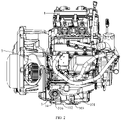
- a powertrain 100 includes an engine 1, a continuously variable transmission 2 and a transmission 3.
- the powertrain 100 may be applied to an all-terrain vehicle 1000.
- the continuously variable transmission 2 is drivingly coupled to the engine 1.
- the transmission 3 includes a casing 31, a power input shaft 32, a first power output shaft 33, and a second power output shaft 34.
- the power input shaft 32, the first power output shaft 33 and the second power output shaft 34 are all provided in the casing 31.
- the power input shaft 32 is drivingly coupled to the continuously variable transmission 2
- the power input shaft 32 is drivingly coupled to the first power output shaft 33 and the second power output shaft 34 separately in the casing 31, and an axis of the power input shaft 32 is parallel to an axis of the first power output shaft 33 and is perpendicular to an axis of the second power output shaft 34.
- the continuously variable transmission 2 is drivingly coupled to the engine 1, the transmission 3 and the engine 1 may both be located at a left side of the continuously variable transmission 2, and in a front-and-rear direction, the engine 1 may be located at a front side of the transmission 3.
- the engine 1 may transmit power to the continuously variable transmission 2
- the continuously variable transmission 2 processes the power and then transmits it to the power input shaft 32 drivingly coupled to the continuously variable transmission 2.
- the continuously variable transmission 2 may transmit the power to the transmission 3, to make the powertrain 100 achieve an effect of variable speed.
- the powertrain 100 can ensure mutual independence of individual parts, and avoid mutual influence of individual parts in the powertrain 100 to promote structural stability of individual parts in the powertrain 100; furthermore, power transmission of the powertrain 100 can be smooth, to promote reliability of the powertrain 100.
- the casing 31 internally defines a relatively sealed space, the power input shaft 32, the first power output shaft 33 and the second power output shaft 34 are all provided in internal space of the casing 31, and the casing 31 may be made of relatively sturdy material. In this way, not only can foreign matter be prevented from entering the casing 31, which damages internal components of the casing 31, but the relatively hard casing 31 can prevent an external force from damaging internal components of the casing 31 when the external force strikes the transmission 3, to promote structural reliability of the transmission 3.
- the power input shaft 32 is drivingly coupled to the first power output shaft 33 and the second power output shaft 34 separately.
- the power input shaft 32 transmits the power to the first power output shaft 33 and the second power output shaft 34 respectively
- the first power output shaft 33 and the second power output shaft 34 may transmit power to different wheels respectively.
- the first power output shaft 33 may transmit power directly to wheels located at a rear side
- the second power output shaft 34 may transmit power directly to wheels located at a front side, to realize four-wheel drive of the vehicle.
- an output end of the second power output shaft 34 protrudes towards the engine 1, and in an axial direction of the power input shaft 32, the second power output shaft 34 is located at a side of the casing 31 closes to the continuously variable transmission 2 than a side of the casing 31 away from the continuously variable transmission 2.
- the output end of the second power output shaft 34 is arranged to protrude towards the engine 1, available space in the powertrain 100 can be fully utilized, to promote space utilization of the powertrain 100, and the structure of the powertrain 100 can be more compact, to reduce occupancy space of the powertrain 100.
- the second power output shaft 34 is arranged at a side of the casing 31 close to the continuously variable transmission 2, and this can facilitates mounting and arrangement of the propeller shaft 10 drivingly coupled to the second power output shaft 34, to make structural layout of the powertrain 100 more reasonable and further promote structural reliability of the powertrain 100.
- the axis of the power input shaft 32 is parallel to the axis of the first power output shaft 33, and the axis of the power input shaft 32 is perpendicular to the axis of the second power output shaft 34, and this can make structural arrangement of the power input shaft 32, the first power output shaft 33 and the second power output shaft 34 reasonable, and the internal structure of the transmission 3 more compact.
- the second power output shaft 34 may fully utilize space in the transmission 3 in a direction perpendicular to the axis of the power input shaft 32, and this not only promotes space utilization, but also realizes power transmission to the propeller shaft 10 located at the front side by changing an output direction, to simplify power transmission path of the powertrain 100 and make power transmission more reliable.
- the internal structure of the casing 31 can be compact, and driving-coupling between the second power output shaft 34 and the corresponding propeller shaft 10 can be facilitated by changing the output direction of the second power output shaft 34.
- a plane perpendicular to an axis direction of the power input shaft 32 is taken as a reference plane, and a projection of the continuously variable transmission 2 on the reference plane and a projection of the second power output shaft 34 on the reference plane at least partially overlap.
- this arrangement makes the structure of the powertrain 100 more compact, and structural arrangement of the powertrain 100 more reasonable, to promote power transmission efficiency of the powertrain 100 and reduce volume of the powertrain 100.
- a gap exists between a projection of the continuously variable transmission 2 on a horizontal plane and a projection of the second power output shaft 34 on the horizontal plane.
- the continuously variable transmission 2 and the second power output shaft 34 may be spaced apart in a coupling direction of the transmission 3 and the continuously variable transmission 2. This arrangement can make the continuously variable transmission 2 and the second power output shaft 34 independent of each other.
- the continuously variable transmission 2 will not affect arrangement and normal operation of the second power output shaft 34, and when the second power output shaft 34 is drivingly coupled to the propeller shaft 10 coupled to the second power output shaft 34, the continuously variable transmission 2 will not hinder driving-coupling of the propeller shaft 10 and the second power output shaft 34. This not only makes the arrangement of the powertrain 100 more reasonable, but also ensures structural reliability of the powertrain 100.
- the casing 31 internally defines a first cavity 315 and a second cavity 316 in communication with each other.
- the power input shaft 32 and the first power output shaft 33 are provided in the first cavity 315
- the second power output shaft 34 is provided in the second cavity 316
- an end of the second cavity 316 towards the engine 1 is configured as an opening from which the second power output shaft 34 protrudes.
- the first sub-casing 311 is arranged opposite the second sub-casing 312 to define a relatively sealed first cavity 315.
- Oppositely arranged first sub-casing 311 and second sub-casing 312 can ensure leakproofness and reliability of the first cavity 315, and can promote strength of the casing 31; the third sub-casing 313 arranged at a side of the first sub-casing 311 away from the second sub-casing 312 can further promote structural strength of the casing 31.
- the power input shaft 32 and the first power output shaft 33 are provided in the first cavity 315.
- the first cavity 315 can provide sufficient space for mounting and arrangement of the power input shaft 32 and the first power output shaft 33, and the first cavity 315 can protect the power input shaft 32 and the first power output shaft 33 from foreign matter damage.
- the second cavity 316 can protect the second power output shaft 34 from damage, and the first cavity 315 and the second cavity 316 can also ensure stability of normal transmission of the power input shaft 32, the first power output shaft 33 and the second power output shaft 34 and avoid mutual interference, to further promote structural stability of the powertrain 100.
- the second power output shaft 34 protrudes from the opening, thus mounting and arrangement of the propeller shaft 10 drivingly coupled to the second power output shaft 34 can be facilitated.
- the second power output shaft 34 is located at a side of the casing 31 close to the continuously variable transmission 2, to ensure mutual fitting of the second power output shaft 34 and the power input shaft 32 and ensure normal power output. This can make overall layout of the powertrain 100 more reasonable, and ensure stability and reliability of the powertrain 100.
- the axis of the first power output shaft 33 is higher than the axis of the second power output shaft 34.
- the second power output shaft 34 needs to protrude through avoidance space 102 of a bottom of an oil sump 101 of the engine 1, and hence the axis of the second power output shaft 34 is provided at a lower position in the transmission 3. Since both the first power output shaft 33 and the second power output shaft 34 are drivingly coupled to the power input shaft 32, and in order to make structural arrangement of the transmission 3 compact and reduce volume of the transmission 3, the axis of the first power output shaft 33 needs to design to be higher than the axis of the second power output shaft 34, and the axis of the first power output shaft 33 and the axis of the second power output shaft 34 are not in a straight line. This can, under the premise of ensuring normal operation of the transmission 3, make internal structure of the transmission 3 more compact, to make overall layout of internal structure of the transmission 3 more reasonable.
- the axis of the first power output shaft 33 is at an angle to the axis of the second power output shaft 34.
- the first power output shaft 33 and the second power output shaft 34 have different power output directions. This can facilitate arrangement of the first power output shaft 33 and the second power output shaft 34 while meeting requirements of power output coupling of the transmission 3 with the outside, to make power output coupling of the transmission 3 with the outside selectable, achieving the effect of variable speed.
- This type of transmission 3 may be applied to a four-wheel drive vehicle.
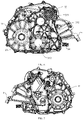
- the transmission 3 further includes a plurality of intermediate shafts 35 drivingly coupled sequentially, the plurality of intermediate shafts 35 are provided in the casing 31 and include a first intermediate shaft 351 drivingly coupled to the power input shaft 32 and a second intermediate shaft 352 drivingly coupled to both of the first power output shaft 33 and the second power output shaft 34, and an axis of the second intermediate shaft 352 is lower than the axis of the first power output shaft 33.
- the first intermediate shaft 351, the second intermediate shaft 352 and the third intermediate shaft 353 are provided in the transmission 3, the power input shaft 32 may transmit power to the first intermediate shaft 351, the first intermediate shaft 351 transmits power to the second intermediate shaft 352, and the second intermediate shaft 352 transmits power to the first power output shaft 33 and the second power output shaft 34, to render the transmission 3 to achieve the effect of variable speed.
- the axis of the second intermediate shaft 352 is lower than the axis of the first power output shaft 33, and this can make structural arrangement of the first intermediate shaft 351 and the second intermediate shaft 352 more reasonable, and facilitate power output from the second intermediate shaft 352 to the first power output shaft 33 and the second power output shaft 34, making internal structure of the transmission 3 more compact and further reducing volume of the transmission 3.
- the axis of the second intermediate shaft 352 is parallel to the axis of the first power output shaft 33 and perpendicular to the axis of the second power output shaft 34.
- the axis of the second intermediate shaft 352 is parallel to the axis of the first power output shaft 33, and the second intermediate shaft 352 can transmit power in parallel with the first power output shaft 33 to output the power.
- the axis of the second intermediate shaft 352 is perpendicular to the axis of the second power output shaft 34, and the second intermediate shaft 352 can transmit power vertically with the second power output shaft 34 to output the power. This can facilitate arrangement of the second intermediate shaft 352, the first power output shaft 33 and the second power output shaft 34 in the transmission, to make the transmission more compact, and make the power output coupling of the transmission with the outside selectable, achieving the effect of variable speed.
- An axis direction of the first power output shaft 33 may be the same as a lateral direction of the vehicle (i.e., a left-and-right direction), and an axis direction of the second power output shaft 34 may be the same as a longitudinal direction of the vehicle (i.e., a front-and-rear direction).
- the first power output shaft 33 can transmit power to a corresponding group of half shafts directly
- the second power output shaft 34 can transmit power to another corresponding group of half shafts through a corresponding propeller shaft 10 and final drive 9.
- the second intermediate shaft 352 and the first power output shaft 33 are provided with a spur gear set or helical gear set therebetween, and the second intermediate shaft 352 and the second power output shaft 34 are provided with a bevel gear set therebetween.
- the spur gear set or the helical gear set are provided between the second intermediate shaft 352 and the first power output shaft 33, to meet the requirements of parallel power transmission between the second intermediate shaft 352 and the first power output shaft 33; and the bevel gear set is provided between the second intermediate shaft 352 and the second power output shaft 34, to meet the requirements of vertical power transmission between the second intermediate shaft 352 and the second power output shaft 34, realizing different power output directions.
- the second intermediate shaft 352 arranged in this way can transmit power to two power output shafts at the same time.
- the second intermediate shaft 352 is provided with a first gear 36, a second gear 37 and a third gear 38.
- the first gear 36 is drivingly fitted with the first intermediate shaft 351
- the second gear 37 is drivingly fitted with the first power output shaft 33
- the third gear 38 is drivingly fitted with the second power output shaft 34.
- the first gear 36, the second gear 37 and the third gear 38 are arranged sequentially in the axial direction, the first gear 36 and the second gear 37 are both provided between the first sub-casing 311 and the second sub-casing 312, and the third gear 38 is provided between the second sub-casing 312 and the fourth sub-casing 314.
- the first gear 36 and a gear of the third intermediate shaft 353 are in meshing transmission, the first intermediate shaft 351 can transmit power to the first gear 36 and rotate the second intermediate shaft 352, the rotation of the second intermediate shaft 352 will drive rotation of the second gear 37 and the third gear 38, and the second gear 37 and the third gear 38 will respectively drive the gear of first power output shaft 33 and the gear of the second power output shaft 34 to rotate, to realize power transmission in the transmission.
- the three gears arranged in this way have reasonable position arrangement, and can make transmission stable and reliable.
- the first sub-casing 311 and the second sub-casing 312 can protect the first gear 36 and the second gear 37 from foreign matter damage
- the second sub-casing 312 and the fourth sub-casing 314 can protect the third gear 38 from foreign matter damage, to promote structural reliability of the second intermediate shaft 352.
- this arrangement can also isolate the first gear 36, the second gear 37 and the third gear 38, and this can ensure that the first gear 36, the second gear 37 and the third gear 38 will not interfere with one another during normal rotation, and that mounting and arrangement of transmission structure of the first gear 36, the second gear 37 and the third gear 38 will not affect one another, to further promote structural reliability of the transmission.
- axes of the plurality of intermediate shafts 35 are arranged in parallel with the axis of the power input shaft 32.
- the axes of the plurality of intermediate shafts 35 and the axis of the power input shaft 32 are arranged in parallel, thus parallel power transmission is formed between the plurality of intermediate shafts 35 and the power input shaft 32, and arrangement of the plurality of intermediate shafts 35 and the power input shaft 32 in the transmission can be more convenient, to reduce volume of the transmission as much as possible.
- the first power output shaft 33 is located obliquely above the second intermediate shaft 352.
- the first power output shaft 33 is provided obliquely above the second intermediate shaft 352, thus power input coupling with the outside can be facilitated, occupancy space of the first power output shaft 33 can be reduced as much as possible, and position arrangement of the second intermediate shaft 352 is more reasonable, realizing power transmission.
- the plurality of intermediate shafts 35 also include a third intermediate shaft 353.
- the third intermediate shaft 353 is drivingly coupled to the first intermediate shaft 351 and the second intermediate shaft 352 separately.
- the power input shaft 32 is located obliquely above the first intermediate shaft 351, the first intermediate shaft 351 is located obliquely above the third intermediate shaft 353, and the third intermediate shaft 353 is located obliquely above the second intermediate shaft 352.
- the third intermediate shaft 353 may also be provided between the first intermediate shaft 351 and the second intermediate shaft 352.
- the first intermediate shaft 351 may transmit power to the third intermediate shaft 353, and the third intermediate shaft 353 transmits power to the second intermediate shaft 352.
- the plurality of intermediate shafts 35 rotate sequentially to avoid unstable power transmission due to sharp power rising or dropping, and this can promote stability and reliability of power transmission of the intermediate shafts 35.
- the plurality of intermediate shafts 35 can accommodate different internal structural arrangements of different transmissions 3, thus applicability of the intermediate shafts 35 can be promoted, the insides of different transmissions 3 can also be relatively compact, and the structural reliability of the transmission 3 can further promoted.
- the power input shaft 32, the first intermediate shaft 351, the second intermediate shaft 352 and the third intermediate shaft 353 arranged in this way can ensure that under the premise of normal transmission of the power input shaft 32, the first intermediate shaft 351, the second intermediate shaft 352 and the third intermediate shaft 353, the internal structure of the transmission can be more compact, the volume of the transmission can be further reduced, and occupancy space of the transmission can be further reduced.
- the power input shaft 32 and the first intermediate shaft 351 are in reduction transmission
- the first intermediate shaft 351 and the third intermediate shaft 353 are in reduction transmission
- the third intermediate shaft 353 and the second intermediate shaft 352 are in reduction transmission
- the second intermediate shaft 352 and the first power output shaft 33 are in reduction transmission
- the second intermediate shaft 352 and second power output shaft 34 are in reduction transmission.
- a plane where an axis of the first intermediate shaft 351 and the axis of the second intermediate shaft 352 lie is a first plane
- the power input shaft 32 and the third intermediate shaft 353 are located at a same side of the first plane
- the power input shaft 32 and the first power output shaft 33 are located at two sides of the first plane, respectively.
- the power input shaft 32 is located obliquely above the first intermediate shaft 351
- the first intermediate shaft 351 is located obliquely above the third intermediate shaft 353
- the third intermediate shaft 353 is located obliquely above the second intermediate shaft 352.
- the power input shaft 32 and the third intermediate shaft 353 are located at the same side (i.e., a front side) of the first plane determined by the axis of the first intermediate shaft 351 and the axis of the second intermediate shaft 352, this makes internal space of transmission in an up-and-down direction occupied by the power input shaft 32, the first intermediate shaft 351, the second intermediate shaft 352 and the third intermediate shaft 353 minimum, and also ensures that internal space of the transmission in the left-and-right direction occupied by the power input shaft 32, the first intermediate shaft 351, the second intermediate shaft 352 and the third intermediate shaft 353 is minimum, to make internal structure of the transmission more compact and further reduce volume of the transmission.
- the power input shaft 32 and the first power output shaft 33 are located at two sides of the first plane formed by the axis of the first intermediate shaft 351 and the axis of the second intermediate shaft 352, respectively.
- the power input shaft 32 and the first power output shaft 33 can fully utilize space of the transmission in the up-and-down direction and in the front-and-rear direction, and under the premise of ensuring normal transmission of the transmission, various shafts of the transmission can be reasonable, and space utilization of the transmission can be promoted, to make internal structure of the transmission more compact and further reduce volume of the transmission.
- the axis of the first power output shaft 33, the axis of the second intermediate shaft 352 and the axis of the second power output shaft 34 are in a non-coplanar relationship.
- the axis of the power input shaft 32 is perpendicular to the axis of the second power output shaft 34, and the axis of the first power output shaft 33, the axis of the second intermediate shaft 352 and the axis of the power input shaft 32 are all arranged in parallel. Hence, the axis of the first power output shaft 33, the axis of the second intermediate shaft 352 and the axis of the second power output shaft 34 are not in a plane.
- the second power output shaft 34 can fully utilize space in the transmission in a direction perpendicular to the axis of the power input shaft 32, and the internal structure of the transmission can be more compact, the volume of the transmission can be further reduced, and forward driving-coupling of the second power output shaft 34 to the corresponding propeller shaft 10 can be convenient.
- a plane where the axis of the second intermediate shaft 352 and the axis of the second power output shaft 34 lie is a second plane, and the power input shaft 32 and the first power output shaft 33 are located at a same side of the second plane.
- the power input shaft 32 and the first power output shaft 33 are located at an upper side of the second plane.
- the power input shaft 32 and the first power output shaft 33 are provided at the upper side of the second plane where the axis of the second intermediate shaft 352 and the axis of the second power output shaft 34 lie, the power input shaft 32 and the first power output shaft 33 can be distributed reasonably, and internal space of the transmission can be fully utilized, to make the structure of the transmission more compact, and further reduce the volume of the transmission.
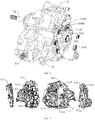
- the casing 31 includes: a first sub-casing 311, a second sub-casing 312, and a third sub-casing 313.
- the first sub-casing 311 is arranged opposite the second sub-casing 312, the first sub-casing 311 defines a first shaft hole 3111, the third sub-casing 313 is detachably coupled to a side of the first sub-casing 311 away from the second sub-casing 312 and covers the first shaft hole 3111.
- the intermediate shaft 35 is provided on the first sub-casing 311 and the second sub-casing 312 and has an end protruding from first shaft hole 3111 towards the third sub-casing 313, an end of the intermediate shaft 35 is provided with a fastener 354, and the fastener 354 is located between the first sub-casing 311 and the third sub-casing 313.
- the first sub-casing 311 and the second sub-casing 312 are arranged oppositely and may fitted with each other to define a mounting space for mounting and arrangement of corresponding components, to ensure structural stability and reliability of the corresponding components.
- the first sub-casing 311 defines the first shaft hole 3111
- the third sub-casing 313 provided at the side of the first sub-casing 311 away from the second sub-casing 312 can cover the first shaft hole 3111.
- the third sub-casing 313 arranged in this way can seal the side of the first sub-casing 311 away from the second sub-casing 312, the structure protruded from the first shaft hole 3111 can be protected from damage, and structural reliability of the transmission 3 can be promoted.
- the third sub-casing 313 is detachably coupled to the side of the first sub-casing 311 away from the second sub-casing 312, structural strength of the casing 31 of the transmission 3 can be further promoted, overall leakproofness of the casing 31 can be further promoted, structural reliability of the transmission 3 can be further promoted, and service life of the transmission 3 may be prolonged.
- this arrangement can also make the third sub-casing 313 easy to mount or detach, to facilitate maintenance or replacement of corresponding internal components of the transmission 3 by a user.
- the intermediate shaft 35 is provided on the first sub-casing 311 and the second sub-casing 312, and an end of the intermediate shaft 35 protrudes from the first shaft hole 3111 towards the third sub-casing 313, and in order to realize axial limit of the intermediate shaft 35, the end of the intermediate shaft 35 protruded from the first shaft hole 3111 towards the third sub-casing 313 is provided with the fastener 354, that is, the fastener 354 is located between the first sub-casing 311 and the third sub-casing 313.
- the intermediate shaft 35 is provided on the first sub-casing 311 and the second sub-casing 312, and the intermediate shaft 35 is rotatable in the mounting space defined by the first sub-casing 311 and the second sub-casing 312, to realize power transmission.
- An end of the intermediate shaft 35 protrudes from the first shaft hole 3111 towards the third sub-casing 313, the fastener 354 is provided on the end of the intermediate shaft 35 protruded from the first shaft hole 3111, and the fastener 354 is fixedly coupled to the intermediate shaft 35.
- the fastener 354 can fix the intermediate shaft 35 axially, and avoid abnormal noise or failure of the transmission 3 due to axial displacement during rotation of the intermediate shaft 35, to further promote structural reliability of the transmission 3.
- the fastener 354 may be fastened on an end of the intermediate shaft 35, and then the third sub-casing 313 is mounted, to reduce mounting difficulty of the fastener 354, and also reduce assembly difficulty of the transmission 3.
- the structure of the casing 31 can be more stable and firm, and the fastener 354 can be conveniently fastened on the end of the intermediate shaft 35, to prevent the position of the intermediate shaft 35 from shifting and promote reliability of the intermediate shaft 35.
- the casing 31 also includes a fourth sub-casing 314.
- the fourth sub-casing 314 is provided at a side of the second sub-casing 312 away from the first sub-casing 311, and defines a second cavity 316 together with the second sub-casing 312, and the second sub-casing 312 and the fourth sub-casing 314 are fixedly coupled to the continuously variable transmission 2.
- the fourth sub-casing 314 is provided at the side of the second sub-casing 312 away from the first sub-casing 311, and the fourth sub-casing 314 and the second sub-casing 312 may be fitted with each other, to define relatively sealed second cavity 316.
- the second power output shaft 34 is provided in the second cavity 316, and the second cavity 316 can protect the second power output shaft 34, to promote structural reliability of the second power output shaft 34.
- the second sub-casing 312 and the fourth sub-casing 314 may be fixedly coupled to the continuously variable transmission 2, and this not only ensures stability and firmness of fixed coupling of the continuously variable transmission 2 and the transmission 3, but also makes structural arrangement of the powertrain 100 more compact, to make overall layout of the powertrain 100 more reasonable and optimize structural design of the powertrain 100.
- the first shaft hole 3111 is internally provided with a first bearing 355, and an end of the intermediate shaft 35 passes through the first bearing 355 and protrudes towards the third sub-casing 313.
- the end of the intermediate shaft 35 protruded from the first shaft hole 3111 towards the third sub-casing 313 is provided with a threaded portion 3501.
- the threaded portion 3501 is an external thread
- the fastener 354 is a nut
- the threaded portion 3501 is an internal thread
- the fastener 354 is a bolt.
- the first bearing 355 is provided in the first shaft hole 3111, an end of the intermediate shaft 35 passes through the first bearing 355 and protrudes towards the third sub-casing 313, and a rolling member is provided between the first bearing 355 and the intermediate shaft 35.
- the first bearing 355 can have a support effect on the intermediate shaft 35, to reduce friction coefficient of the intermediate shaft 35 during rotation. This arrangement can promote rotation efficiency of the intermediate shaft 35, reduce power loss due to frictional force during rotation of the intermediate shaft 35, reduce structural wear of the intermediate shaft 35 and the first sub-casing 311, and prolong service life of the intermediate shaft 35.
- the first bearing 355 can also ensure rotary accuracy of the intermediate shaft 35, to further promote reliability of the transmission 3.
- the fastener 354 may be a nut, and the nut may be threaded onto the external thread, to realize fixing coupling of the fastener 354 with the end of the intermediate shaft 35; correspondingly, when the end of the intermediate shaft 35 protruded from the first shaft hole 3111 is hollow, and the threaded portion 3501 on the end of the intermediate shaft 35 protruded from the first shaft hole 3111 is configured to have an internal thread on an inner wall of the intermediate shaft 35, the fastener 354 may be a bolt, and the bolt extends into the inside of the intermediate shaft 35 and is threaded onto the internal thread on the inner wall of the intermediate shaft 35, to realize fixing coupling of the fastener 354 and the end of the intermediate shaft 35.
- This arrangement can, under the premise of ensuring tight and firm coupling of the fastener 354 and the end of the intermediate shaft 35, selectively set the type of the threaded portion 3501 and the fastener 354 fitted with the threaded portion 3501 according to structural requirements of the transmission 3, which not only facilitates production and manufacture, but also promote applicability of the intermediate shaft 35.
- the fastener 354 may be limited at an outer side of the first bearing 355, to ensure axial stability of the intermediate shaft 35.
- first sub-casing 311 defines a plurality of first shaft holes 3111, ends of the plurality of intermediate shafts 35 protrude from respective first shaft holes 3111, and the third sub-casing 313 covers the plurality of first shaft holes 3111.
- first sub-casing 311 defines the plurality of first shaft holes 3111, and the plurality of intermediate shafts 35 are provided in one-to-one correspondence to the plurality of first shaft holes 3111. This arrangement can avoid failure of the transmission 3 due to mutual contact and mutual influence of the ends of the plurality of intermediate shafts 35 during normal rotation of the plurality of intermediate shafts 35, and can further promote stability and reliability of the intermediate shafts 35.
- Three intermediate shafts 35 may be provided. It could be understood that, a plurality of fasteners 354 may fasten respective intermediate shafts 35 at the same side, and then be sealed together with the third sub-casing 313, and this can make the structure of the transmission 3 simpler and assembly efficiency higher.
- the first sub-casing 311 defines a second shaft hole 3112
- the fourth sub-casing 314 defines a third shaft hole 3141
- the second sub-casing 312 defines the first cavity 315.
- the power input shaft 32 passes through the first cavity 315 and two ends of the power input shaft 32 protrude from the second shaft hole 3112 and the third shaft hole 3141, respectively, and the third sub-casing 313 also covers the second shaft hole 3112.
- a first end of the power input shaft 32 passes through the first cavity 315 defined in the second sub-casing 312, and then protrudes from the third shaft hole 3141 of the fourth sub-casing 314 for power input coupling; a second end of the power input shaft 32 protrudes from the second shaft hole 3112 of the first sub-casing 311, and is covered by the third sub-casing 313.
- This arrangement can, under the premise of ensuring normal power input of the power input shaft 32, render the power input shaft 32 to be mounted and arranged in the transmission 3 more stably and firmly, to further promote structural reliability of the transmission 3.
- the second sub-casing 312 also defines the second cavity 316, the first intermediate shaft 351 and the third intermediate shaft 353 pass through the first cavity 315, and the second intermediate shaft 352 passes through the second cavity 316 to drivingly fitted with the second power output shaft 34.
- the first intermediate shaft 351, the third intermediate shaft 353 and the power input shaft 32 together pass through the first cavity 315.
- the first intermediate shaft 351, the third intermediate shaft 353 and the power input shaft 32 can be ensured to protrude from the second sub-casing 312, the first intermediate shaft 351, the third intermediate shaft 353 and the power input shaft 32 can share the first cavity 315, and manufacturing process of the second sub-casing 312 can be simplified under the premise of no influence on normal operation of the first intermediate shaft 351, the third intermediate shaft 353, the second intermediate shaft 352 and the power input shaft 32.
- this can not only make internal structure of the transmission 3 more compact, but also reduce weight of the transmission 3.
- a side of the second sub-casing 312 towards the fourth sub-casing 314 defines a first accommodating space 5
- a side of the fourth sub-casing 314 towards the second sub-casing 312 defines a second accommodating space 6
- the first accommodating space 5 and the second accommodating space 6 are arranged oppositely, to define an accommodating space for the second power output shaft 34.
- An end portion of the second power output shaft 34 protrudes from the accommodating space, and an angle between the second power output shaft 34 and the power input shaft 32 is 90 degrees.
- an angle exists between an arrangement direction of the second power output shaft 34 and an arrangement direction of the power input shaft 32, the intermediate shaft 35 and the first power output shaft 33, the side of the second sub-casing 312 towards the fourth sub-casing 314 defines the first accommodating space 5, the side of the fourth sub-casing 314 towards the second sub-casing 312 defines the second accommodating space 6, the first accommodating space 5 and the second accommodating space 6 are arranged oppositely to define relatively sealed accommodating space, to correspond to the second power output shaft 34, and the second power output shaft 34 may be provided in it; furthermore, the end portion of the second power output shaft 34 protrudes from the accommodating space, this not only further promotes stability of mounting and arrangement of the second power output shaft 34, but also ensures relative independence of the second power output shaft 34.
- the angle between the second power output shaft 34 and the power input shaft 32 is 90 degrees, and the second power output shaft 34 arranged in this way can fully utilize space of the casing 31 in a direction perpendicular to the power input shaft 32.
- the structural layout of the transmission 3 can be more reasonable, to make structure of the transmission 3 more compact and further reduce volume of the transmission 3.
- the first accommodating space 5 internally defines at least two first arc-shaped grooves 51
- the second accommodating space 6 internally defines at least two second arc-shaped grooves 61
- the at least two first arc-shaped grooves 51 and the at least two second arc-shaped grooves 61 are arranged oppositely respectively to define at least two circular mounting grooves.
- the second power output shaft 34 is fitted with at least two second bearings 43, and the at least two second bearings 43 are provided in the mounting grooves, respectively.
- the at least two first arc-shaped grooves 51 and the at least two second arc-shaped grooves 61 are arranged oppositely to define the at least two circular mounting grooves
- the second power output shaft 34 is provided in the mounting grooves
- the second power output shaft 34 is fitted with at least two second bearings 43.
- the second bearings 43 are located between the second power output shaft 34 and the mounting grooves, and the second bearings 43 can have a support effect on the second power output shaft 34, to reduce friction coefficient of the second power output shaft 34 during rotation.
- This arrangement can not only promote rotation efficiency of the second power output shaft 34 to reduce power loss due to a relatively large frictional force during rotation of the second power output shaft 34, but also reduce structural wear of the second power output shaft 34 and the first sub-casing 311 to prolong the service life of the second power output shaft 34.
- the second bearing 43 can also ensure rotary accuracy of the second power output shaft 34, to further promote reliability of the transmission 3.
- a bottom of the engine 1 defines an avoidance space 102 for avoiding the propeller shaft 10 coupled to the second power output shaft 34.
- the avoidance space 102 of the bottom of the engine 1 can prevent the engine 1 from shielding the second power output shaft 34, and expose the second power output shaft 34, and coupling and arrangement of the propeller shaft 10 and the second power output shaft 34 can be convenient. This can not only facilitate mounting and arrangement of the propeller shaft 10 to ensure normal operation of the powertrain 100, but also can optimize structural design of the powertrain 100 without changing position of the engine 1.
- the engine 1 includes an oil sump 101, a middle of the oil sump 101 defines an oil storage portion 103 recessed downwards, and a side of the oil storage portion 103 towards the continuously variable transmission 2 is provided with the avoidance space 102.
- the oil sump 101 may stores lubrication oil, to maintain normal operation of the engine 1.
- the position of the oil sump 101 corresponds to a position of the second power output shaft 34, and in order to prevent the oil sump 101 from shielding the second power output shaft 34 and from hindering the mounting and arrangement of the second power output shaft 34 and the propeller shaft 10, the middle of the oil sump 101 is provided with the oil storage portion 103 recessed downwards, and the avoidance space 102 is provided in a side of the oil storage portion 103 towards the continuously variable transmission 2.
- the oil sump 101 needs not to be changed, and under the premise of ensuring normal oil storage function of the oil storage portion 103, the oil sump 101 is prevented from affecting mounting and arrangement of the propeller shaft 10 and the second power output shaft 34 by ingeniously designing the shape of the oil sump 101.
- the ingenious design can not only ensure structural reliability of the powertrain 100, but also optimize the structural design of the powertrain 100.
- the transmission 3 is provided with a mounting platform, and the mounting platform is fixedly coupled to the engine 1 by the fastener 354.
- the casing 31 may be fixedly coupled to the engine 1 through the mounting platform 4, and the power input shaft 32 is coupled to the engine 1 in power input mode.
- the power input shaft 32 is rotatable under the drive of the engine 1, to ensure normal operation of the transmission 3.
- the transmission 3 can be produced and manufactured separately, and then wholly mounted onto the engine 1, to improve integrity of the transmission 3.
- the mounting platform may be mounted at an intake side or an exhaust side of the engine 1, correspondingly.
- a plurality of mounting platforms 4 are provided, and the plurality of mounting platforms 4 are spaced apart at a side of the casing 31, and the mounting platform 4 defines a mounting via hole 41 and/or a positioning pin hole 42.
- a plurality of mounting platforms 4 are provided, and the plurality of mounting platforms 4 can ensure degree of fixity of the side of the casing 31 with the engine 1; furthermore, the plurality of mounting platforms 4 are spaced apart at the side of the casing 31, and the side of the casing 31 can be fixed to the engine 1 more tightly, to avoid clearance between the side of the casing 31 and the engine 1.
- four mounting platforms 4 are provided, and the four mounting platforms 4 are arranged in two rows and two columns.
- One of the two mounting platforms 4 in the same row is provided with the mounting via hole 41, and the other is provided with the mounting via hole 41 and the positioning pin hole 42; one of the two mounting platforms 4 in the same column is provided with the mounting via hole 41, and the other is provided with the mounting via hole 41 and the positioning pin hole 42.
- mounting platforms 4 are provided, and the four mounting platforms 4 are arranged in two rows and two columns, to render the side of the casing 31 to be better fixedly coupled to the engine 1. Furthermore, one of the two mounting platforms 4 located in the same row is provided with the mounting via hole 41, and the other is provided with the mounting via hole 41 and the positioning pin hole 42; one of the two mounting platforms 4 in the same column is provided with the mounting via hole 41, and the other is provided with the mounting via hole 41 and the positioning pin hole 42; and the fastener 354 and a positioning pin can fix the mounting platform 4 onto the engine 1 through the mounting via hole 41 and the positioning pin hole 42, and this arrangement is more reasonable, to ensure balance of fixing between the side of the casing 31 and the engine 1.
- the engine 1 is internally provided with a crankshaft, a power output end of the crankshaft is coupled to a power input end of the continuously variable transmission 2, and a power output end of the continuously variable transmission 2 is coupled to the power input end of the transmission 3.
- the engine 1, the continuously variable transmission 2 and the transmission 3 are coupled to one another, and collectively form a part of the powertrain 100, the engine 1 transmits power to the power input end of the continuously variable transmission 2 through the power output end of the crankshaft, and the continuously variable transmission 2 processes the power and then transmits the power to the power input end of the transmission 3 through the power output end, to power the transmission 3.
- power transmission in the powertrain 100 can be stable and continuous, to promote the reliability of the powertrain 100.
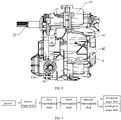
- the all-terrain vehicle 1000 includes two first half shafts 7, a propeller shaft 10 and a powertrain 100.
- the powertrain 100 is a powertrain 100 according to any one of the above embodiments.
- a first end of the first power output shaft 33 is coupled to one of the first half shafts 7, a second first power output shaft 33 is coupled to the other of the first half shafts 7, and an end of the second power output shaft 34 is drivingly coupled to the propeller shaft 10.
- the power input shaft 32 is drivingly coupled to the first power output shaft 33 and the second power output shaft 34.
- the power input shaft 32 will transmit the power to the first power output shaft 33 and the second power output shaft 34 separately, the first end of the first power output shaft 33 is coupled to one of the first half shafts 7, the second end of the first power output shaft 33 is coupled to the other of the first half shafts 7, and the end of the second power output shaft 34 is drivingly coupled to the propeller shaft 10.
- the power can be directly output to the first half shafts 7 from the first power output shaft 33, and then to wheels coupled to the first half shafts 7.
- the transmission path can be effectively shortened, the transmission process can be simplified, the transmission stability can be improved, arrangement flexibility of the components of the all-terrain vehicle 1000 in a front-and-rear direction can be promoted, and mounting and arrangement difficulty can be reduced.
- the second power output shaft 34 can also output power to other half shafts through the propeller shaft 10, and four-wheel drive of the all-terrain vehicle 1000 can be realized, to promote power performance and driving stability of the all-terrain vehicle 1000.
- an end portion of the first half shaft 7 is provided with a first spline portion 71
- an end portion of the first power output shaft 33 is provided with a second spline portion 332
- the first spline portion 71 is spline-fitted to the second spline portion 332.
- the first power output shaft 33 and the first half shaft 7 can employ spline fit, the spline fit is simple and convenient, and the transmission is stable.
- the first spline portion 71 is an external spline
- the second spline portion 332 is an internal spline
- two ends of the first power output shaft 33 are located in the casing 31, and define the mounting grooves 331
- the inner peripheral wall of each mounting groove 331 forms the internal spline.
- the end portion of the first half shaft 7 will extend into the mounting groove 331, and then the spline fit is achieved.
- the overall length of the transmission 3 and the two first half shafts 7 in the axial direction can be effectively shortened, to promote balance and stability of the all-terrain vehicle 1000.
- the first sub-casing 311 is provided with a first opening 3113 corresponding to an end portion of the first power output shaft 33, one of the first half shafts 7 is coupled to an end portion of the first power output shaft 33 through the first opening 3113.
- the second sub-casing 312 is provided with a second opening 3121 corresponding to the other end portion of the first power output shaft 33, and the other of the first half shafts 7 is coupled to the other end portion of the first power output shaft 33 through the second opening 3121.
- the end portion of the first half shaft 770 can conveniently extend into the casing 3120 for driving coupling, and this can reduce lateral width of the all-terrain vehicle 1000, and facilitate reasonable overall layout of the all-terrain vehicle 1000.
- the all-terrain vehicle 1000 also includes: a final drive 9 and two second half shafts 8.
- the final drive 9 is drivingly coupled to the propeller shaft 10, a first end of the final drive 9 is coupled to one of the second half shafts 8, and a second end of the final drive 9 is coupled to the other of the second half shafts 8.
- the engine 1, the continuously variable transmission 2 and the transmission 3 can transmit power to one another.
- the transmission 3 can also transmit power to the first half shaft 7 and the propeller shaft 10, the propeller shaft 10 can be coupled to the final drive 9, and the final drive 9 can also be coupled to the second half shafts 8. Since the final drive 9 is drivingly coupled to the propeller shaft 10, the first end of the final drive 9 is coupled to one of the second half shafts 8, and the second end of the final drive 9 is coupled to the other of the second half shafts 8.
- the power transmitted to the propeller shaft 10 can be transmitted to the wheels through the final drive 9 and the second half shafts 8.
- the first half shaft 7 may be a rear half shaft
- the second half shaft 8 may be a front half shaft.
- the all-terrain vehicle 1000 also includes front wheels 11 and rear wheels 12, the first power output shaft 33 is coupled to the rear wheels 12, and the second power output shaft 34 is coupled to the front wheels 11.
- the transmission 3 obtains power through the power input shaft 32, and the power will undergo variable speed process and then is output through the first power output end and the second power output end respectively.
- the first power output shaft 33 may be coupled to the rear wheels 12 and can transmit power to the rear wheels 12
- the second power output shaft 34 may be coupled to the front wheels 11 and can transmit power to the front wheels 11, to realize four-wheel drive of the all-terrain vehicle 1000 and promote performance of the all-terrain vehicle 1000.
- first and second are used herein for purposes of description and are not intended to indicate or imply relative importance or significance.
- the feature defined with “first” and “second” may comprise one or more of this feature.
- the term “a plurality of' means two or more than two, unless specified otherwise.
- the terms “mounted,” “connected,” “coupled,” “fixed” and the like are used broadly, and may be, for example, fixed connections, detachable connections, or integral connections; may also be mechanical or electrical connections; may also be direct connections or indirect connections via intervening structures; may also be inner communications of two elements.
- the above terms can be understood by those skilled in the art according to specific situations.
- a structure in which a first feature is “on” or “below” a second feature may include an embodiment in which the first feature is in direct contact with the second feature, and may also include an embodiment in which the first feature and the second feature are not in direct contact with each other, but are contacted via an additional feature formed therebetween.
- a first feature "on,” “above,” or “on top of' a second feature may include an embodiment in which the first feature is right or obliquely “on,” “above,” or “on top of' the second feature, or just means that the first feature is at a height higher than that of the second feature.
- first feature "below,” “under,” or “on bottom of' a second feature may include an embodiment in which the first feature is right or obliquely “below,” “under,” or “on bottom of' the second feature, or just means that the first feature is at a height lower than that of the second feature.
Landscapes
- Engineering & Computer Science (AREA)
- Mechanical Engineering (AREA)
- General Engineering & Computer Science (AREA)
- Chemical & Material Sciences (AREA)
- Combustion & Propulsion (AREA)
- Transportation (AREA)
- Transmission Devices (AREA)
Abstract
Description
- The present invention relates to the field of vehicle technologies, and more particularly, to a powertrain and an all-terrain vehicle.
- At present, in the all-terrain vehicles available on the markets, an engine and a transmission are integrally formed, and the engine and the transmission share a lubrication system, which speeds up wear of the engine and the transmission. The engine and the transmission arranged in this way not only have poor stability, but are also inconvenient to be mounted and arranged with a propeller shaft of the all-terrain vehicles.
- The present invention seeks to solve at least one of the problems existing in the related art to at least some extent. To this end, embodiments of the present invention propose a powertrain, which has better stability and reasonable structural arrangement.
- Embodiments of the present invention also propose an all-terrain vehicle.
- According to one aspect, the present invention provides a powertrain as set out in
claim 1. According to another aspect, the present invention provides an all-terrain vehicle as set out in claim 13. - The powertrain according to embodiments of the present invention includes an engine, a continuously variable transmission and a transmission. The continuously variable transmission is drivingly coupled to the engine. The transmission includes a casing, a power input shaft, a first power output shaft and a second power output shaft. The power input shaft, the first power output shaft and the second power output shaft are all provided in the casing. The power input shaft is drivingly coupled to the continuously variable transmission, the power input shaft is drivingly coupled to the first power output shaft and the second power output shaft separately in the casing, and an axis of the power input shaft is parallel to an axis of the first power output shaft and perpendicular to an axis of the second power output shaft.
- In the powertrain of embodiments of the present invention, the power input shaft is drivingly coupled to the continuously variable transmission to allow reasonable overall layout of the powertrain, making overall stability of the powertrain better and optimizing structural design of the powertrain; the axis of the power input shaft is arranged in parallel with the axis of the first power output shaft and the power input shaft is perpendicular to the axis of the second power output shaft, thus the casing can have a compact internal structure, and driving-coupling between the second power output shaft and the corresponding propeller shaft can be facilitated by changing an output direction of the second power output shaft.
- In some embodiments, the continuously variable transmission is drivingly coupled to the engine, the second power output shaft has an output end protruded towards the engine, and in an axial direction of the power input shaft, the second power output shaft is located at a side of the casing close to the continuously variable transmission than a side of the casing away from the continuously variable transmission.
- In some embodiments, a plane perpendicular to an axis direction of the power input shaft is taken as a reference plane, and a projection of the continuously variable transmission on the reference plane and a projection of the second power output shaft on the reference plane at least partially overlap.
- In some embodiments, when the powertrain is mounted on a vehicle, a gap exists between a projection of the continuously variable transmission on a horizontal plane and a projection of the second power output shaft on the horizontal plane.
- In some embodiments, the axis of the first power output shaft is higher than the axis of the second power output shaft.
- In some embodiments, the axis of the first power output shaft is at an angle to the axis of the second power output shaft.
- In some embodiments, the transmission further includes a plurality of intermediate shafts drivingly coupled sequentially, the plurality of intermediate shafts are provided in the casing and include a first intermediate shaft drivingly coupled to the power input shaft and a second intermediate shaft drivingly coupled to both of the first power output shaft and the second power output shaft, and an axis of the second intermediate shaft is lower than the axis of the first power output shaft.
- In some embodiments, the axis of the second intermediate shaft is parallel to the axis of the first power output shaft and perpendicular to the axis of the second power output shaft.
- In some embodiments, the second intermediate shaft and the first power output shaft are provided with a spur gear set or helical gear set therebetween, and the second intermediate shaft and the second power output shaft are provided with a bevel gear set therebetween.
- In some embodiments, axes of the plurality of intermediate shafts are arranged in parallel with the axis of the power input shaft.
- In some embodiments, the first power output shaft is located obliquely above the second intermediate shaft.
- In some embodiments, the plurality of intermediate shafts further include a third intermediate shaft drivingly coupled to the first intermediate shaft and the second intermediate shaft separately, the power input shaft is located obliquely above the first intermediate shaft, the first intermediate shaft is located obliquely above the third intermediate shaft, and the third intermediate shaft is located obliquely above the second intermediate shaft.
- In some embodiments, a plane where an axis of the first intermediate shaft and the axis of the second intermediate shaft lie is a first plane, the power input shaft and the third intermediate shaft are located at a same side of the first plane, and the power input shaft and the first power output shaft are located at two sides of the first plane, respectively.
- In some embodiments, a plane where the axis of the second intermediate shaft and the axis of the second power output shaft lie is a second plane, and the power input shaft and the first power output shaft are located at a same side of the second plane.
- In some embodiments, the casing includes a first sub-casing, a second sub-casing and a third sub-casing; the first sub-casing is arranged opposite the second sub-casing, the first sub-casing defines a first shaft hole, the third sub-casing is detachably coupled to a side of the first sub-casing away from the second sub-casing and covers the first shaft hole; and the intermediate shafts are provided on the first sub-casing and the second sub-casing and have an end protruded from the first shaft hole towards the third sub-casing.
- The all-terrain vehicle according to embodiments of the present invention includes two first half shafts; a propeller shaft; and a powertrain according to any one of the above-described embodiments, the first power output shaft has a first end coupled to one of the first half shafts and a second end coupled to the other of the first half shafts, the second power output shaft has an end drivingly coupled to the propeller shaft.
- In the all-terrain vehicle of embodiments of the present invention, one final drive is omitted by replacing the final drive with the transmission, power can be output to the first half shafts directly from the first power output shaft and then to wheels coupled to the first half shafts. Thus, the transmission path can be effectively shortened, the transmission process can be simplified, the transmission stability can be improved, arrangement flexibility of components of the all-terrain vehicle in a front-and-rear direction can be promoted, and the arrangement difficulty can be reduced.
- In some embodiments, an end portion of the first half shaft is provided with a first spline portion, an end portion of the first power output shaft is provided with a second spline portion, and the first spline portion is spline-fitted to the second spline portion.
- In some embodiments, the first spline portion is an external spine, the second spline portion is an internal spline, two ends of the first power output shaft are located in the casing and define mounting grooves, and the internal spline is formed on an inner peripheral wall of each mounting groove.
- In some embodiments, the all-terrain vehicle further includes a final drive and two second half shafts, the final drive is drivingly coupled to the propeller shaft, the final drive has an end coupled to one of the second half shafts, and the second end of the first power output shaft is drivingly coupled to the other of the second half shafts.
- In some embodiments, the all-terrain vehicle further includes a front wheel and a rear wheel, the first power output shaft is coupled to the rear wheel, and the second power output shaft is coupled to the front wheel.
-
-
FIG. 1 is a schematic view of a powertrain according to an embodiment of the present invention from a first perspective. -
FIG. 2 is a schematic view of a powertrain according to an embodiment of the present invention from a second perspective. -
FIG. 3 is a schematic view of a transmission in a powertrain according to an embodiment of the present invention, with a second sub-casing and a fourth sub-casing removed. -
FIG. 4 is a schematic view of a transmission in a powertrain according to an embodiment of the present invention from another perspective. -
FIG. 5 is an exploded view of a casing of a transmission in a powertrain according to an embodiment of the present invention. -
FIG. 6 is a first plan view of a transmission according to an embodiment of the present invention. -
FIG. 7 is a second plan view of a transmission according to an embodiment of the present invention. -
FIG. 8 is a third plan view of a transmission according to an embodiment of the present invention. -
FIG. 9 is a flow chart of power transmission of a powertrain according to an embodiment of the present invention. -
FIG. 10 is a schematic view of an all-terrain vehicle according to an embodiment of the present invention. - Embodiments of the present invention will be described in detail below, and examples of the embodiments are shown in accompanying drawings. The embodiments described herein with reference to drawings are explanatory, illustrative, and used to generally understand the present invention. The embodiments shall not be construed to limit the present invention.
- As illustrated in
FIGS. 1 to 9 , apowertrain 100 according to embodiments of the present invention includes anengine 1, a continuouslyvariable transmission 2 and atransmission 3. Thepowertrain 100 may be applied to an all-terrain vehicle 1000. - The continuously
variable transmission 2 is drivingly coupled to theengine 1. - The
transmission 3 includes acasing 31, apower input shaft 32, a firstpower output shaft 33, and a secondpower output shaft 34. - The
power input shaft 32, the firstpower output shaft 33 and the secondpower output shaft 34 are all provided in thecasing 31. Thepower input shaft 32 is drivingly coupled to the continuouslyvariable transmission 2, thepower input shaft 32 is drivingly coupled to the firstpower output shaft 33 and the secondpower output shaft 34 separately in thecasing 31, and an axis of thepower input shaft 32 is parallel to an axis of the firstpower output shaft 33 and is perpendicular to an axis of the secondpower output shaft 34. - In at least one embodiment, as illustrated in
FIGS. 1 to 4 , the continuouslyvariable transmission 2 is drivingly coupled to theengine 1, thetransmission 3 and theengine 1 may both be located at a left side of the continuouslyvariable transmission 2, and in a front-and-rear direction, theengine 1 may be located at a front side of thetransmission 3. - When the
powertrain 100 is in normal operation, theengine 1 may transmit power to the continuouslyvariable transmission 2, the continuouslyvariable transmission 2 processes the power and then transmits it to thepower input shaft 32 drivingly coupled to the continuouslyvariable transmission 2. Thus the continuouslyvariable transmission 2 may transmit the power to thetransmission 3, to make thepowertrain 100 achieve an effect of variable speed. - Thus, the
powertrain 100 can ensure mutual independence of individual parts, and avoid mutual influence of individual parts in thepowertrain 100 to promote structural stability of individual parts in thepowertrain 100; furthermore, power transmission of thepowertrain 100 can be smooth, to promote reliability of thepowertrain 100. - In addition, with reference to
FIGS. 3 ,6 ,7 and5 , thecasing 31 internally defines a relatively sealed space, thepower input shaft 32, the firstpower output shaft 33 and the secondpower output shaft 34 are all provided in internal space of thecasing 31, and thecasing 31 may be made of relatively sturdy material. In this way, not only can foreign matter be prevented from entering thecasing 31, which damages internal components of thecasing 31, but the relativelyhard casing 31 can prevent an external force from damaging internal components of thecasing 31 when the external force strikes thetransmission 3, to promote structural reliability of thetransmission 3. - Further, the
power input shaft 32 is drivingly coupled to the firstpower output shaft 33 and the secondpower output shaft 34 separately. In at least one embodiment, after the continuouslyvariable transmission 2 transmits power to thepower input shaft 32, thepower input shaft 32 transmits the power to the firstpower output shaft 33 and the secondpower output shaft 34 respectively, and the firstpower output shaft 33 and the secondpower output shaft 34 may transmit power to different wheels respectively. This not only makes structure of thetransmission 3 compact, but also promotes performance of the vehicle. For example, the firstpower output shaft 33 may transmit power directly to wheels located at a rear side, and the secondpower output shaft 34 may transmit power directly to wheels located at a front side, to realize four-wheel drive of the vehicle. - With reference to
FIGS. 1 and8 , an output end of the secondpower output shaft 34 protrudes towards theengine 1, and in an axial direction of thepower input shaft 32, the secondpower output shaft 34 is located at a side of thecasing 31 closes to the continuouslyvariable transmission 2 than a side of thecasing 31 away from the continuouslyvariable transmission 2. In at least one embodiment, the output end of the secondpower output shaft 34 is arranged to protrude towards theengine 1, available space in thepowertrain 100 can be fully utilized, to promote space utilization of thepowertrain 100, and the structure of thepowertrain 100 can be more compact, to reduce occupancy space of thepowertrain 100. Furthermore, the secondpower output shaft 34 is arranged at a side of thecasing 31 close to the continuouslyvariable transmission 2, and this can facilitates mounting and arrangement of thepropeller shaft 10 drivingly coupled to the secondpower output shaft 34, to make structural layout of thepowertrain 100 more reasonable and further promote structural reliability of thepowertrain 100. - Thus, by drivingly coupling the
power input shaft 32 to the continuouslyvariable transmission 2 and arranging the secondpower output shaft 34 at a side of thecasing 31 close to the continuouslyvariable transmission 2, mounting and arrangement of thepropeller shaft 10 drivingly coupled to the secondpower output shaft 34 can be facilitated, and the overall layout of thepowertrain 100 can be reasonable, to make overall stability of thepowertrain 100 better and optimize the structural design of thepowertrain 100. - With reference to
FIGS. 3 and6 , the axis of thepower input shaft 32 is parallel to the axis of the firstpower output shaft 33, and the axis of thepower input shaft 32 is perpendicular to the axis of the secondpower output shaft 34, and this can make structural arrangement of thepower input shaft 32, the firstpower output shaft 33 and the secondpower output shaft 34 reasonable, and the internal structure of thetransmission 3 more compact. In addition, the secondpower output shaft 34 may fully utilize space in thetransmission 3 in a direction perpendicular to the axis of thepower input shaft 32, and this not only promotes space utilization, but also realizes power transmission to thepropeller shaft 10 located at the front side by changing an output direction, to simplify power transmission path of thepowertrain 100 and make power transmission more reliable. - Thus, by arranging the axis of the
power input shaft 32 to be parallel to the axis of the firstpower output shaft 33 and arranging the axis of thepower input shaft 32 to be perpendicular to the axis of the secondpower output shaft 34, the internal structure of thecasing 31 can be compact, and driving-coupling between the secondpower output shaft 34 and thecorresponding propeller shaft 10 can be facilitated by changing the output direction of the secondpower output shaft 34. - In some embodiments, a plane perpendicular to an axis direction of the
power input shaft 32 is taken as a reference plane, and a projection of the continuouslyvariable transmission 2 on the reference plane and a projection of the secondpower output shaft 34 on the reference plane at least partially overlap. - In at least one embodiment, as illustrated in
FIG. 1 , in the case where arrangement of the continuouslyvariable transmission 2 does not affect normal arrangement and operation of the secondpower output shaft 34, this arrangement makes the structure of thepowertrain 100 more compact, and structural arrangement of thepowertrain 100 more reasonable, to promote power transmission efficiency of thepowertrain 100 and reduce volume of thepowertrain 100. - In some embodiments, when the
powertrain 100 is mounted on a vehicle, a gap exists between a projection of the continuouslyvariable transmission 2 on a horizontal plane and a projection of the secondpower output shaft 34 on the horizontal plane. - In at least one embodiment, the continuously
variable transmission 2 and the secondpower output shaft 34 may be spaced apart in a coupling direction of thetransmission 3 and the continuouslyvariable transmission 2. This arrangement can make the continuouslyvariable transmission 2 and the secondpower output shaft 34 independent of each other. The continuouslyvariable transmission 2 will not affect arrangement and normal operation of the secondpower output shaft 34, and when the secondpower output shaft 34 is drivingly coupled to thepropeller shaft 10 coupled to the secondpower output shaft 34, the continuouslyvariable transmission 2 will not hinder driving-coupling of thepropeller shaft 10 and the secondpower output shaft 34. This not only makes the arrangement of thepowertrain 100 more reasonable, but also ensures structural reliability of thepowertrain 100. - In some embodiments, the
casing 31 internally defines afirst cavity 315 and asecond cavity 316 in communication with each other. Thepower input shaft 32 and the firstpower output shaft 33 are provided in thefirst cavity 315, the secondpower output shaft 34 is provided in thesecond cavity 316, and an end of thesecond cavity 316 towards theengine 1 is configured as an opening from which the secondpower output shaft 34 protrudes. - In at least one embodiment, as illustrated in
FIGS. 1 ,3 and6 , thefirst sub-casing 311 is arranged opposite thesecond sub-casing 312 to define a relatively sealedfirst cavity 315. Oppositely arrangedfirst sub-casing 311 and second sub-casing 312 can ensure leakproofness and reliability of thefirst cavity 315, and can promote strength of thecasing 31; the third sub-casing 313 arranged at a side of thefirst sub-casing 311 away from thesecond sub-casing 312 can further promote structural strength of thecasing 31. Thepower input shaft 32 and the firstpower output shaft 33 are provided in thefirst cavity 315. Thefirst cavity 315 can provide sufficient space for mounting and arrangement of thepower input shaft 32 and the firstpower output shaft 33, and thefirst cavity 315 can protect thepower input shaft 32 and the firstpower output shaft 33 from foreign matter damage. Thesecond cavity 316 can protect the secondpower output shaft 34 from damage, and thefirst cavity 315 and thesecond cavity 316 can also ensure stability of normal transmission of thepower input shaft 32, the firstpower output shaft 33 and the secondpower output shaft 34 and avoid mutual interference, to further promote structural stability of thepowertrain 100. - In at least one embodiment, as illustrated in
FIGS. 3 and6 , the secondpower output shaft 34 protrudes from the opening, thus mounting and arrangement of thepropeller shaft 10 drivingly coupled to the secondpower output shaft 34 can be facilitated. In addition, in the axial direction of thepower input shaft 32, the secondpower output shaft 34 is located at a side of thecasing 31 close to the continuouslyvariable transmission 2, to ensure mutual fitting of the secondpower output shaft 34 and thepower input shaft 32 and ensure normal power output. This can make overall layout of thepowertrain 100 more reasonable, and ensure stability and reliability of thepowertrain 100. - In some embodiments, the axis of the first
power output shaft 33 is higher than the axis of the secondpower output shaft 34. - In at least one embodiment, as illustrated in
FIGS. 3 and6 , the secondpower output shaft 34 needs to protrude through avoidance space 102 of a bottom of anoil sump 101 of theengine 1, and hence the axis of the secondpower output shaft 34 is provided at a lower position in thetransmission 3. Since both the firstpower output shaft 33 and the secondpower output shaft 34 are drivingly coupled to thepower input shaft 32, and in order to make structural arrangement of thetransmission 3 compact and reduce volume of thetransmission 3, the axis of the firstpower output shaft 33 needs to design to be higher than the axis of the secondpower output shaft 34, and the axis of the firstpower output shaft 33 and the axis of the secondpower output shaft 34 are not in a straight line. This can, under the premise of ensuring normal operation of thetransmission 3, make internal structure of thetransmission 3 more compact, to make overall layout of internal structure of thetransmission 3 more reasonable. - In some embodiments, the axis of the first
power output shaft 33 is at an angle to the axis of the secondpower output shaft 34. - In at least one embodiment, as illustrated in
FIG. 3 , that is to say, the firstpower output shaft 33 and the secondpower output shaft 34 have different power output directions. This can facilitate arrangement of the firstpower output shaft 33 and the secondpower output shaft 34 while meeting requirements of power output coupling of thetransmission 3 with the outside, to make power output coupling of thetransmission 3 with the outside selectable, achieving the effect of variable speed. This type oftransmission 3 may be applied to a four-wheel drive vehicle. - In some embodiments, the
transmission 3 further includes a plurality ofintermediate shafts 35 drivingly coupled sequentially, the plurality ofintermediate shafts 35 are provided in thecasing 31 and include a firstintermediate shaft 351 drivingly coupled to thepower input shaft 32 and a secondintermediate shaft 352 drivingly coupled to both of the firstpower output shaft 33 and the secondpower output shaft 34, and an axis of the secondintermediate shaft 352 is lower than the axis of the firstpower output shaft 33. - In at least one embodiment, as illustrated in
FIGS. 3 and6 , the firstintermediate shaft 351, the secondintermediate shaft 352 and the thirdintermediate shaft 353 are provided in thetransmission 3, thepower input shaft 32 may transmit power to the firstintermediate shaft 351, the firstintermediate shaft 351 transmits power to the secondintermediate shaft 352, and the secondintermediate shaft 352 transmits power to the firstpower output shaft 33 and the secondpower output shaft 34, to render thetransmission 3 to achieve the effect of variable speed. The axis of the secondintermediate shaft 352 is lower than the axis of the firstpower output shaft 33, and this can make structural arrangement of the firstintermediate shaft 351 and the secondintermediate shaft 352 more reasonable, and facilitate power output from the secondintermediate shaft 352 to the firstpower output shaft 33 and the secondpower output shaft 34, making internal structure of thetransmission 3 more compact and further reducing volume of thetransmission 3. - In some embodiments, the axis of the second
intermediate shaft 352 is parallel to the axis of the firstpower output shaft 33 and perpendicular to the axis of the secondpower output shaft 34. - As illustrated in
FIG. 3 , the axis of the secondintermediate shaft 352 is parallel to the axis of the firstpower output shaft 33, and the secondintermediate shaft 352 can transmit power in parallel with the firstpower output shaft 33 to output the power. The axis of the secondintermediate shaft 352 is perpendicular to the axis of the secondpower output shaft 34, and the secondintermediate shaft 352 can transmit power vertically with the secondpower output shaft 34 to output the power. This can facilitate arrangement of the secondintermediate shaft 352, the firstpower output shaft 33 and the secondpower output shaft 34 in the transmission, to make the transmission more compact, and make the power output coupling of the transmission with the outside selectable, achieving the effect of variable speed. - An axis direction of the first
power output shaft 33 may be the same as a lateral direction of the vehicle (i.e., a left-and-right direction), and an axis direction of the secondpower output shaft 34 may be the same as a longitudinal direction of the vehicle (i.e., a front-and-rear direction). Thus, the firstpower output shaft 33 can transmit power to a corresponding group of half shafts directly, and the secondpower output shaft 34 can transmit power to another corresponding group of half shafts through acorresponding propeller shaft 10 andfinal drive 9. - In some embodiments, the second
intermediate shaft 352 and the firstpower output shaft 33 are provided with a spur gear set or helical gear set therebetween, and the secondintermediate shaft 352 and the secondpower output shaft 34 are provided with a bevel gear set therebetween. - In at least one embodiment, as illustrated in
FIG. 3 , the spur gear set or the helical gear set are provided between the secondintermediate shaft 352 and the firstpower output shaft 33, to meet the requirements of parallel power transmission between the secondintermediate shaft 352 and the firstpower output shaft 33; and the bevel gear set is provided between the secondintermediate shaft 352 and the secondpower output shaft 34, to meet the requirements of vertical power transmission between the secondintermediate shaft 352 and the secondpower output shaft 34, realizing different power output directions. The secondintermediate shaft 352 arranged in this way can transmit power to two power output shafts at the same time. - In at least one embodiment, as illustrated in
FIG. 3 , the secondintermediate shaft 352 is provided with afirst gear 36, asecond gear 37 and athird gear 38. Thefirst gear 36 is drivingly fitted with the firstintermediate shaft 351, thesecond gear 37 is drivingly fitted with the firstpower output shaft 33, and thethird gear 38 is drivingly fitted with the secondpower output shaft 34. Thefirst gear 36, thesecond gear 37 and thethird gear 38 are arranged sequentially in the axial direction, thefirst gear 36 and thesecond gear 37 are both provided between thefirst sub-casing 311 and thesecond sub-casing 312, and thethird gear 38 is provided between thesecond sub-casing 312 and thefourth sub-casing 314. - The
first gear 36 and a gear of the thirdintermediate shaft 353 are in meshing transmission, the firstintermediate shaft 351 can transmit power to thefirst gear 36 and rotate the secondintermediate shaft 352, the rotation of the secondintermediate shaft 352 will drive rotation of thesecond gear 37 and thethird gear 38, and thesecond gear 37 and thethird gear 38 will respectively drive the gear of firstpower output shaft 33 and the gear of the secondpower output shaft 34 to rotate, to realize power transmission in the transmission. The three gears arranged in this way have reasonable position arrangement, and can make transmission stable and reliable. - The
first sub-casing 311 and thesecond sub-casing 312 can protect thefirst gear 36 and thesecond gear 37 from foreign matter damage, and thesecond sub-casing 312 and thefourth sub-casing 314 can protect thethird gear 38 from foreign matter damage, to promote structural reliability of the secondintermediate shaft 352. In addition, this arrangement can also isolate thefirst gear 36, thesecond gear 37 and thethird gear 38, and this can ensure that thefirst gear 36, thesecond gear 37 and thethird gear 38 will not interfere with one another during normal rotation, and that mounting and arrangement of transmission structure of thefirst gear 36, thesecond gear 37 and thethird gear 38 will not affect one another, to further promote structural reliability of the transmission. - In some embodiments, axes of the plurality of
intermediate shafts 35 are arranged in parallel with the axis of thepower input shaft 32. - In at least one embodiment, as illustrated in
FIG. 3 , the axes of the plurality ofintermediate shafts 35 and the axis of thepower input shaft 32 are arranged in parallel, thus parallel power transmission is formed between the plurality ofintermediate shafts 35 and thepower input shaft 32, and arrangement of the plurality ofintermediate shafts 35 and thepower input shaft 32 in the transmission can be more convenient, to reduce volume of the transmission as much as possible. - In some embodiments, the first
power output shaft 33 is located obliquely above the secondintermediate shaft 352. - In at least one embodiment, as illustrated in
FIG. 3 , the firstpower output shaft 33 is provided obliquely above the secondintermediate shaft 352, thus power input coupling with the outside can be facilitated, occupancy space of the firstpower output shaft 33 can be reduced as much as possible, and position arrangement of the secondintermediate shaft 352 is more reasonable, realizing power transmission. - In some embodiments, the plurality of
intermediate shafts 35 also include a thirdintermediate shaft 353. The thirdintermediate shaft 353 is drivingly coupled to the firstintermediate shaft 351 and the secondintermediate shaft 352 separately. Thepower input shaft 32 is located obliquely above the firstintermediate shaft 351, the firstintermediate shaft 351 is located obliquely above the thirdintermediate shaft 353, and the thirdintermediate shaft 353 is located obliquely above the secondintermediate shaft 352. - In at least one embodiment, as illustrated in
FIGS. 3 and6 , the thirdintermediate shaft 353 may also be provided between the firstintermediate shaft 351 and the secondintermediate shaft 352. The firstintermediate shaft 351 may transmit power to the thirdintermediate shaft 353, and the thirdintermediate shaft 353 transmits power to the secondintermediate shaft 352. The plurality ofintermediate shafts 35 rotate sequentially to avoid unstable power transmission due to sharp power rising or dropping, and this can promote stability and reliability of power transmission of theintermediate shafts 35. In addition, by arranging the plurality ofintermediate shafts 35 reasonably, the plurality ofintermediate shafts 35 can accommodate different internal structural arrangements ofdifferent transmissions 3, thus applicability of theintermediate shafts 35 can be promoted, the insides ofdifferent transmissions 3 can also be relatively compact, and the structural reliability of thetransmission 3 can further promoted. - Since various shafts in the transmission are provided with round gears, the
power input shaft 32, the firstintermediate shaft 351, the secondintermediate shaft 352 and the thirdintermediate shaft 353 arranged in this way can ensure that under the premise of normal transmission of thepower input shaft 32, the firstintermediate shaft 351, the secondintermediate shaft 352 and the thirdintermediate shaft 353, the internal structure of the transmission can be more compact, the volume of the transmission can be further reduced, and occupancy space of the transmission can be further reduced. - The
power input shaft 32 and the firstintermediate shaft 351 are in reduction transmission, the firstintermediate shaft 351 and the thirdintermediate shaft 353 are in reduction transmission, the thirdintermediate shaft 353 and the secondintermediate shaft 352 are in reduction transmission, the secondintermediate shaft 352 and the firstpower output shaft 33 are in reduction transmission, and the secondintermediate shaft 352 and secondpower output shaft 34 are in reduction transmission. Thus, power undergoes multi-stage reduction transmission, and stability of the power output of theengine 1 of the all-terrain vehicle 1000 can be ensured. - In some embodiments, a plane where an axis of the first
intermediate shaft 351 and the axis of the secondintermediate shaft 352 lie is a first plane, thepower input shaft 32 and the thirdintermediate shaft 353 are located at a same side of the first plane, and thepower input shaft 32 and the firstpower output shaft 33 are located at two sides of the first plane, respectively. - In at least one embodiment, as illustrated in
FIGS. 3 and7 , thepower input shaft 32 is located obliquely above the firstintermediate shaft 351, the firstintermediate shaft 351 is located obliquely above the thirdintermediate shaft 353, and the thirdintermediate shaft 353 is located obliquely above the secondintermediate shaft 352. Hence, thepower input shaft 32 and the thirdintermediate shaft 353 are located at the same side (i.e., a front side) of the first plane determined by the axis of the firstintermediate shaft 351 and the axis of the secondintermediate shaft 352, this makes internal space of transmission in an up-and-down direction occupied by thepower input shaft 32, the firstintermediate shaft 351, the secondintermediate shaft 352 and the thirdintermediate shaft 353 minimum, and also ensures that internal space of the transmission in the left-and-right direction occupied by thepower input shaft 32, the firstintermediate shaft 351, the secondintermediate shaft 352 and the thirdintermediate shaft 353 is minimum, to make internal structure of the transmission more compact and further reduce volume of the transmission. - The
power input shaft 32 and the firstpower output shaft 33 are located at two sides of the first plane formed by the axis of the firstintermediate shaft 351 and the axis of the secondintermediate shaft 352, respectively. Thus, thepower input shaft 32 and the firstpower output shaft 33 can fully utilize space of the transmission in the up-and-down direction and in the front-and-rear direction, and under the premise of ensuring normal transmission of the transmission, various shafts of the transmission can be reasonable, and space utilization of the transmission can be promoted, to make internal structure of the transmission more compact and further reduce volume of the transmission. - In some embodiments, the axis of the first
power output shaft 33, the axis of the secondintermediate shaft 352 and the axis of the secondpower output shaft 34 are in a non-coplanar relationship. - In at least one embodiment, as illustrated in
FIGS. 3 and7 , the axis of thepower input shaft 32 is perpendicular to the axis of the secondpower output shaft 34, and the axis of the firstpower output shaft 33, the axis of the secondintermediate shaft 352 and the axis of thepower input shaft 32 are all arranged in parallel. Hence, the axis of the firstpower output shaft 33, the axis of the secondintermediate shaft 352 and the axis of the secondpower output shaft 34 are not in a plane. Thus, the secondpower output shaft 34 can fully utilize space in the transmission in a direction perpendicular to the axis of thepower input shaft 32, and the internal structure of the transmission can be more compact, the volume of the transmission can be further reduced, and forward driving-coupling of the secondpower output shaft 34 to thecorresponding propeller shaft 10 can be convenient. - In some embodiments, a plane where the axis of the second
intermediate shaft 352 and the axis of the secondpower output shaft 34 lie is a second plane, and thepower input shaft 32 and the firstpower output shaft 33 are located at a same side of the second plane. - In at least one embodiment, as illustrated in
FIGS. 3 and7 , thepower input shaft 32 and the firstpower output shaft 33 are located at an upper side of the second plane. Thepower input shaft 32 and the firstpower output shaft 33 are provided at the upper side of the second plane where the axis of the secondintermediate shaft 352 and the axis of the secondpower output shaft 34 lie, thepower input shaft 32 and the firstpower output shaft 33 can be distributed reasonably, and internal space of the transmission can be fully utilized, to make the structure of the transmission more compact, and further reduce the volume of the transmission. - In some embodiments, the
casing 31 includes: afirst sub-casing 311, asecond sub-casing 312, and athird sub-casing 313. Thefirst sub-casing 311 is arranged opposite thesecond sub-casing 312, thefirst sub-casing 311 defines afirst shaft hole 3111, thethird sub-casing 313 is detachably coupled to a side of thefirst sub-casing 311 away from thesecond sub-casing 312 and covers thefirst shaft hole 3111. Theintermediate shaft 35 is provided on thefirst sub-casing 311 and thesecond sub-casing 312 and has an end protruding fromfirst shaft hole 3111 towards thethird sub-casing 313, an end of theintermediate shaft 35 is provided with afastener 354, and thefastener 354 is located between thefirst sub-casing 311 and thethird sub-casing 313. - In at least one embodiment, as illustrated in
FIG. 5 , thefirst sub-casing 311 and thesecond sub-casing 312 are arranged oppositely and may fitted with each other to define a mounting space for mounting and arrangement of corresponding components, to ensure structural stability and reliability of the corresponding components. - Further, the
first sub-casing 311 defines thefirst shaft hole 3111, and thethird sub-casing 313 provided at the side of thefirst sub-casing 311 away from thesecond sub-casing 312 can cover thefirst shaft hole 3111. The third sub-casing 313 arranged in this way can seal the side of thefirst sub-casing 311 away from thesecond sub-casing 312, the structure protruded from thefirst shaft hole 3111 can be protected from damage, and structural reliability of thetransmission 3 can be promoted. - In addition, as illustrated in
FIG. 5 , thethird sub-casing 313 is detachably coupled to the side of thefirst sub-casing 311 away from thesecond sub-casing 312, structural strength of thecasing 31 of thetransmission 3 can be further promoted, overall leakproofness of thecasing 31 can be further promoted, structural reliability of thetransmission 3 can be further promoted, and service life of thetransmission 3 may be prolonged. In addition, this arrangement can also make the third sub-casing 313 easy to mount or detach, to facilitate maintenance or replacement of corresponding internal components of thetransmission 3 by a user. - As illustrated in
FIG. 4 , theintermediate shaft 35 is provided on thefirst sub-casing 311 and thesecond sub-casing 312, and an end of theintermediate shaft 35 protrudes from thefirst shaft hole 3111 towards thethird sub-casing 313, and in order to realize axial limit of theintermediate shaft 35, the end of theintermediate shaft 35 protruded from thefirst shaft hole 3111 towards thethird sub-casing 313 is provided with thefastener 354, that is, thefastener 354 is located between thefirst sub-casing 311 and thethird sub-casing 313. In at least one embodiment, theintermediate shaft 35 is provided on thefirst sub-casing 311 and thesecond sub-casing 312, and theintermediate shaft 35 is rotatable in the mounting space defined by thefirst sub-casing 311 and thesecond sub-casing 312, to realize power transmission. An end of theintermediate shaft 35 protrudes from thefirst shaft hole 3111 towards thethird sub-casing 313, thefastener 354 is provided on the end of theintermediate shaft 35 protruded from thefirst shaft hole 3111, and thefastener 354 is fixedly coupled to theintermediate shaft 35. Thus, thefastener 354 can fix theintermediate shaft 35 axially, and avoid abnormal noise or failure of thetransmission 3 due to axial displacement during rotation of theintermediate shaft 35, to further promote structural reliability of thetransmission 3. - In the process of production and assembly of the
transmission 3, thefastener 354 may be fastened on an end of theintermediate shaft 35, and then thethird sub-casing 313 is mounted, to reduce mounting difficulty of thefastener 354, and also reduce assembly difficulty of thetransmission 3. - Thus, four sub-casings are fitted with one another to form the
casing 31 of thetransmission 3, the structure of thecasing 31 can be more stable and firm, and thefastener 354 can be conveniently fastened on the end of theintermediate shaft 35, to prevent the position of theintermediate shaft 35 from shifting and promote reliability of theintermediate shaft 35. - Further, as illustrated in
FIG. 5 , thecasing 31 also includes afourth sub-casing 314. Thefourth sub-casing 314 is provided at a side of thesecond sub-casing 312 away from thefirst sub-casing 311, and defines asecond cavity 316 together with thesecond sub-casing 312, and thesecond sub-casing 312 and thefourth sub-casing 314 are fixedly coupled to the continuouslyvariable transmission 2. In at least one embodiment, thefourth sub-casing 314 is provided at the side of thesecond sub-casing 312 away from thefirst sub-casing 311, and thefourth sub-casing 314 and thesecond sub-casing 312 may be fitted with each other, to define relatively sealedsecond cavity 316. The secondpower output shaft 34 is provided in thesecond cavity 316, and thesecond cavity 316 can protect the secondpower output shaft 34, to promote structural reliability of the secondpower output shaft 34. Furthermore, thesecond sub-casing 312 and thefourth sub-casing 314 may be fixedly coupled to the continuouslyvariable transmission 2, and this not only ensures stability and firmness of fixed coupling of the continuouslyvariable transmission 2 and thetransmission 3, but also makes structural arrangement of thepowertrain 100 more compact, to make overall layout of thepowertrain 100 more reasonable and optimize structural design of thepowertrain 100. - In some embodiments, the
first shaft hole 3111 is internally provided with afirst bearing 355, and an end of theintermediate shaft 35 passes through thefirst bearing 355 and protrudes towards thethird sub-casing 313. The end of theintermediate shaft 35 protruded from thefirst shaft hole 3111 towards thethird sub-casing 313 is provided with a threadedportion 3501. The threadedportion 3501 is an external thread, and thefastener 354 is a nut; or the threadedportion 3501 is an internal thread, and thefastener 354 is a bolt. - In at least one embodiment, as illustrated in
FIG. 4 , thefirst bearing 355 is provided in thefirst shaft hole 3111, an end of theintermediate shaft 35 passes through thefirst bearing 355 and protrudes towards thethird sub-casing 313, and a rolling member is provided between thefirst bearing 355 and theintermediate shaft 35. Thus, thefirst bearing 355 can have a support effect on theintermediate shaft 35, to reduce friction coefficient of theintermediate shaft 35 during rotation. This arrangement can promote rotation efficiency of theintermediate shaft 35, reduce power loss due to frictional force during rotation of theintermediate shaft 35, reduce structural wear of theintermediate shaft 35 and thefirst sub-casing 311, and prolong service life of theintermediate shaft 35. In addition, thefirst bearing 355 can also ensure rotary accuracy of theintermediate shaft 35, to further promote reliability of thetransmission 3. - Further, when the threaded
portion 3501 on the end of theintermediate shaft 35 protruded from thefirst shaft hole 3111 is the external thread, thefastener 354 may be a nut, and the nut may be threaded onto the external thread, to realize fixing coupling of thefastener 354 with the end of theintermediate shaft 35; correspondingly, when the end of theintermediate shaft 35 protruded from thefirst shaft hole 3111 is hollow, and the threadedportion 3501 on the end of theintermediate shaft 35 protruded from thefirst shaft hole 3111 is configured to have an internal thread on an inner wall of theintermediate shaft 35, thefastener 354 may be a bolt, and the bolt extends into the inside of theintermediate shaft 35 and is threaded onto the internal thread on the inner wall of theintermediate shaft 35, to realize fixing coupling of thefastener 354 and the end of theintermediate shaft 35. This arrangement can, under the premise of ensuring tight and firm coupling of thefastener 354 and the end of theintermediate shaft 35, selectively set the type of the threadedportion 3501 and thefastener 354 fitted with the threadedportion 3501 according to structural requirements of thetransmission 3, which not only facilitates production and manufacture, but also promote applicability of theintermediate shaft 35. Thefastener 354 may be limited at an outer side of thefirst bearing 355, to ensure axial stability of theintermediate shaft 35. - As illustrated in
FIGS. 3 and4 , thefirst sub-casing 311 defines a plurality offirst shaft holes 3111, ends of the plurality ofintermediate shafts 35 protrude from respectivefirst shaft holes 3111, and the third sub-casing 313 covers the plurality of first shaft holes 3111. In at least one embodiment,first sub-casing 311 defines the plurality offirst shaft holes 3111, and the plurality ofintermediate shafts 35 are provided in one-to-one correspondence to the plurality of first shaft holes 3111. This arrangement can avoid failure of thetransmission 3 due to mutual contact and mutual influence of the ends of the plurality ofintermediate shafts 35 during normal rotation of the plurality ofintermediate shafts 35, and can further promote stability and reliability of theintermediate shafts 35. Threeintermediate shafts 35 may be provided. It could be understood that, a plurality offasteners 354 may fasten respectiveintermediate shafts 35 at the same side, and then be sealed together with thethird sub-casing 313, and this can make the structure of thetransmission 3 simpler and assembly efficiency higher. - In some embodiments, the
first sub-casing 311 defines asecond shaft hole 3112, thefourth sub-casing 314 defines athird shaft hole 3141, and thesecond sub-casing 312 defines thefirst cavity 315. Thepower input shaft 32 passes through thefirst cavity 315 and two ends of thepower input shaft 32 protrude from thesecond shaft hole 3112 and thethird shaft hole 3141, respectively, and thethird sub-casing 313 also covers thesecond shaft hole 3112. - As illustrated in
FIG. 5 , a first end of thepower input shaft 32 passes through thefirst cavity 315 defined in thesecond sub-casing 312, and then protrudes from thethird shaft hole 3141 of thefourth sub-casing 314 for power input coupling; a second end of thepower input shaft 32 protrudes from thesecond shaft hole 3112 of thefirst sub-casing 311, and is covered by thethird sub-casing 313. This arrangement can, under the premise of ensuring normal power input of thepower input shaft 32, render thepower input shaft 32 to be mounted and arranged in thetransmission 3 more stably and firmly, to further promote structural reliability of thetransmission 3. - In some embodiments, the
second sub-casing 312 also defines thesecond cavity 316, the firstintermediate shaft 351 and the thirdintermediate shaft 353 pass through thefirst cavity 315, and the secondintermediate shaft 352 passes through thesecond cavity 316 to drivingly fitted with the secondpower output shaft 34. - In at least one embodiment, as illustrated in
FIG. 4 , the firstintermediate shaft 351, the thirdintermediate shaft 353 and thepower input shaft 32 together pass through thefirst cavity 315. Thus, the firstintermediate shaft 351, the thirdintermediate shaft 353 and thepower input shaft 32 can be ensured to protrude from thesecond sub-casing 312, the firstintermediate shaft 351, the thirdintermediate shaft 353 and thepower input shaft 32 can share thefirst cavity 315, and manufacturing process of thesecond sub-casing 312 can be simplified under the premise of no influence on normal operation of the firstintermediate shaft 351, the thirdintermediate shaft 353, the secondintermediate shaft 352 and thepower input shaft 32. In addition, this can not only make internal structure of thetransmission 3 more compact, but also reduce weight of thetransmission 3. - In some embodiments, a side of the
second sub-casing 312 towards thefourth sub-casing 314 defines a firstaccommodating space 5, a side of thefourth sub-casing 314 towards thesecond sub-casing 312 defines a second accommodating space 6, and the firstaccommodating space 5 and the second accommodating space 6 are arranged oppositely, to define an accommodating space for the secondpower output shaft 34. An end portion of the secondpower output shaft 34 protrudes from the accommodating space, and an angle between the secondpower output shaft 34 and thepower input shaft 32 is 90 degrees. - In at least one embodiment, as illustrated in
FIG. 5 , an angle exists between an arrangement direction of the secondpower output shaft 34 and an arrangement direction of thepower input shaft 32, theintermediate shaft 35 and the firstpower output shaft 33, the side of thesecond sub-casing 312 towards thefourth sub-casing 314 defines the firstaccommodating space 5, the side of thefourth sub-casing 314 towards thesecond sub-casing 312 defines the second accommodating space 6, the firstaccommodating space 5 and the second accommodating space 6 are arranged oppositely to define relatively sealed accommodating space, to correspond to the secondpower output shaft 34, and the secondpower output shaft 34 may be provided in it; furthermore, the end portion of the secondpower output shaft 34 protrudes from the accommodating space, this not only further promotes stability of mounting and arrangement of the secondpower output shaft 34, but also ensures relative independence of the secondpower output shaft 34. - Further, with reference to
FIGS. 3 and7 , the angle between the secondpower output shaft 34 and thepower input shaft 32 is 90 degrees, and the secondpower output shaft 34 arranged in this way can fully utilize space of thecasing 31 in a direction perpendicular to thepower input shaft 32. Thus, not only can space utilization be promoted, but also the structural layout of thetransmission 3 can be more reasonable, to make structure of thetransmission 3 more compact and further reduce volume of thetransmission 3. - In some embodiments, the first
accommodating space 5 internally defines at least two first arc-shapedgrooves 51, the second accommodating space 6 internally defines at least two second arc-shapedgrooves 61, and the at least two first arc-shapedgrooves 51 and the at least two second arc-shapedgrooves 61 are arranged oppositely respectively to define at least two circular mounting grooves. The secondpower output shaft 34 is fitted with at least twosecond bearings 43, and the at least twosecond bearings 43 are provided in the mounting grooves, respectively. - In at least one embodiment, as illustrated in
FIG. 5 , the at least two first arc-shapedgrooves 51 and the at least two second arc-shapedgrooves 61 are arranged oppositely to define the at least two circular mounting grooves, the secondpower output shaft 34 is provided in the mounting grooves, and the secondpower output shaft 34 is fitted with at least twosecond bearings 43. Thesecond bearings 43 are located between the secondpower output shaft 34 and the mounting grooves, and thesecond bearings 43 can have a support effect on the secondpower output shaft 34, to reduce friction coefficient of the secondpower output shaft 34 during rotation. This arrangement can not only promote rotation efficiency of the secondpower output shaft 34 to reduce power loss due to a relatively large frictional force during rotation of the secondpower output shaft 34, but also reduce structural wear of the secondpower output shaft 34 and thefirst sub-casing 311 to prolong the service life of the secondpower output shaft 34. In addition, thesecond bearing 43 can also ensure rotary accuracy of the secondpower output shaft 34, to further promote reliability of thetransmission 3. - In some embodiments, a bottom of the
engine 1 defines an avoidance space 102 for avoiding thepropeller shaft 10 coupled to the secondpower output shaft 34. - In at least one embodiment, as illustrated in
FIG. 1 , the avoidance space 102 of the bottom of theengine 1 can prevent theengine 1 from shielding the secondpower output shaft 34, and expose the secondpower output shaft 34, and coupling and arrangement of thepropeller shaft 10 and the secondpower output shaft 34 can be convenient. This can not only facilitate mounting and arrangement of thepropeller shaft 10 to ensure normal operation of thepowertrain 100, but also can optimize structural design of thepowertrain 100 without changing position of theengine 1. - In some embodiments, the
engine 1 includes anoil sump 101, a middle of theoil sump 101 defines anoil storage portion 103 recessed downwards, and a side of theoil storage portion 103 towards the continuouslyvariable transmission 2 is provided with the avoidance space 102. - In at least one embodiment, as illustrated in
FIGS. 1 and2 , theoil sump 101 may stores lubrication oil, to maintain normal operation of theengine 1. The position of theoil sump 101 corresponds to a position of the secondpower output shaft 34, and in order to prevent theoil sump 101 from shielding the secondpower output shaft 34 and from hindering the mounting and arrangement of the secondpower output shaft 34 and thepropeller shaft 10, the middle of theoil sump 101 is provided with theoil storage portion 103 recessed downwards, and the avoidance space 102 is provided in a side of theoil storage portion 103 towards the continuouslyvariable transmission 2. Thus, arranged position of theoil sump 101 needs not to be changed, and under the premise of ensuring normal oil storage function of theoil storage portion 103, theoil sump 101 is prevented from affecting mounting and arrangement of thepropeller shaft 10 and the secondpower output shaft 34 by ingeniously designing the shape of theoil sump 101. The ingenious design can not only ensure structural reliability of thepowertrain 100, but also optimize the structural design of thepowertrain 100. - In some embodiments, the
transmission 3 is provided with a mounting platform, and the mounting platform is fixedly coupled to theengine 1 by thefastener 354. - In at least one embodiment, as illustrated in
FIGS. 6 and 7 , thecasing 31 may be fixedly coupled to theengine 1 through the mountingplatform 4, and thepower input shaft 32 is coupled to theengine 1 in power input mode. Thepower input shaft 32 is rotatable under the drive of theengine 1, to ensure normal operation of thetransmission 3. In addition, by providing the mounting platform, thetransmission 3 can be produced and manufactured separately, and then wholly mounted onto theengine 1, to improve integrity of thetransmission 3. The mounting platform may be mounted at an intake side or an exhaust side of theengine 1, correspondingly. - In at least one embodiment, as illustrated in
FIGS. 6 to 8 , a plurality of mountingplatforms 4 are provided, and the plurality of mountingplatforms 4 are spaced apart at a side of thecasing 31, and the mountingplatform 4 defines a mounting viahole 41 and/or apositioning pin hole 42. A plurality of mountingplatforms 4 are provided, and the plurality of mountingplatforms 4 can ensure degree of fixity of the side of thecasing 31 with theengine 1; furthermore, the plurality of mountingplatforms 4 are spaced apart at the side of thecasing 31, and the side of thecasing 31 can be fixed to theengine 1 more tightly, to avoid clearance between the side of thecasing 31 and theengine 1. - In at least one embodiment, as illustrated in
FIG. 6 , four mountingplatforms 4 are provided, and the fourmounting platforms 4 are arranged in two rows and two columns. One of the two mountingplatforms 4 in the same row is provided with the mounting viahole 41, and the other is provided with the mounting viahole 41 and thepositioning pin hole 42; one of the two mountingplatforms 4 in the same column is provided with the mounting viahole 41, and the other is provided with the mounting viahole 41 and thepositioning pin hole 42. - Four mounting
platforms 4 are provided, and the fourmounting platforms 4 are arranged in two rows and two columns, to render the side of thecasing 31 to be better fixedly coupled to theengine 1. Furthermore, one of the two mountingplatforms 4 located in the same row is provided with the mounting viahole 41, and the other is provided with the mounting viahole 41 and thepositioning pin hole 42; one of the two mountingplatforms 4 in the same column is provided with the mounting viahole 41, and the other is provided with the mounting viahole 41 and thepositioning pin hole 42; and thefastener 354 and a positioning pin can fix the mountingplatform 4 onto theengine 1 through the mounting viahole 41 and thepositioning pin hole 42, and this arrangement is more reasonable, to ensure balance of fixing between the side of thecasing 31 and theengine 1. - In some embodiments, the
engine 1 is internally provided with a crankshaft, a power output end of the crankshaft is coupled to a power input end of the continuouslyvariable transmission 2, and a power output end of the continuouslyvariable transmission 2 is coupled to the power input end of thetransmission 3. - In at least one embodiment, as illustrated in
FIG. 2 , theengine 1, the continuouslyvariable transmission 2 and thetransmission 3 are coupled to one another, and collectively form a part of thepowertrain 100, theengine 1 transmits power to the power input end of the continuouslyvariable transmission 2 through the power output end of the crankshaft, and the continuouslyvariable transmission 2 processes the power and then transmits the power to the power input end of thetransmission 3 through the power output end, to power thetransmission 3. Thus, power transmission in thepowertrain 100 can be stable and continuous, to promote the reliability of thepowertrain 100. - The all-
terrain vehicle 1000 according to embodiments of the present invention includes two first half shafts 7, apropeller shaft 10 and apowertrain 100. - The
powertrain 100 is apowertrain 100 according to any one of the above embodiments. A first end of the firstpower output shaft 33 is coupled to one of the first half shafts 7, a second firstpower output shaft 33 is coupled to the other of the first half shafts 7, and an end of the secondpower output shaft 34 is drivingly coupled to thepropeller shaft 10. - In at least one embodiment, as illustrated in
FIGS. 3 ,6 and 7 , thepower input shaft 32 is drivingly coupled to the firstpower output shaft 33 and the secondpower output shaft 34. After the continuouslyvariable transmission 2 transmits power to thepower input shaft 32, thepower input shaft 32 will transmit the power to the firstpower output shaft 33 and the secondpower output shaft 34 separately, the first end of the firstpower output shaft 33 is coupled to one of the first half shafts 7, the second end of the firstpower output shaft 33 is coupled to the other of the first half shafts 7, and the end of the secondpower output shaft 34 is drivingly coupled to thepropeller shaft 10. - In the all-
terrain vehicle 1000 according to embodiments of the present invention, at least onefinal drive 9 is omitted by replacing thefinal drive 9 with thetransmission 3, the power can be directly output to the first half shafts 7 from the firstpower output shaft 33, and then to wheels coupled to the first half shafts 7. Thus, the transmission path can be effectively shortened, the transmission process can be simplified, the transmission stability can be improved, arrangement flexibility of the components of the all-terrain vehicle 1000 in a front-and-rear direction can be promoted, and mounting and arrangement difficulty can be reduced. In addition, the secondpower output shaft 34 can also output power to other half shafts through thepropeller shaft 10, and four-wheel drive of the all-terrain vehicle 1000 can be realized, to promote power performance and driving stability of the all-terrain vehicle 1000. - In some embodiments, an end portion of the first half shaft 7 is provided with a
first spline portion 71, an end portion of the firstpower output shaft 33 is provided with asecond spline portion 332, and thefirst spline portion 71 is spline-fitted to thesecond spline portion 332. - In at least one embodiment, as illustrated in
FIG. 3 , the firstpower output shaft 33 and the first half shaft 7 can employ spline fit, the spline fit is simple and convenient, and the transmission is stable. - In some embodiments, the
first spline portion 71 is an external spline, thesecond spline portion 332 is an internal spline, two ends of the firstpower output shaft 33 are located in thecasing 31, and define the mountinggrooves 331, and the inner peripheral wall of each mountinggroove 331 forms the internal spline. - In at least one embodiment, as illustrated in
FIG. 3 , the end portion of the first half shaft 7 will extend into the mountinggroove 331, and then the spline fit is achieved. Thus, the overall length of thetransmission 3 and the two first half shafts 7 in the axial direction can be effectively shortened, to promote balance and stability of the all-terrain vehicle 1000. - In some embodiments, the
first sub-casing 311 is provided with afirst opening 3113 corresponding to an end portion of the firstpower output shaft 33, one of the first half shafts 7 is coupled to an end portion of the firstpower output shaft 33 through thefirst opening 3113. Thesecond sub-casing 312 is provided with asecond opening 3121 corresponding to the other end portion of the firstpower output shaft 33, and the other of the first half shafts 7 is coupled to the other end portion of the firstpower output shaft 33 through thesecond opening 3121. Thus, by providing thefirst opening 3113 and thesecond opening 3121, the end portion of the first half shaft 770 can conveniently extend into the casing 3120 for driving coupling, and this can reduce lateral width of the all-terrain vehicle 1000, and facilitate reasonable overall layout of the all-terrain vehicle 1000. - In some embodiments, the all-
terrain vehicle 1000 also includes: afinal drive 9 and two second half shafts 8. Thefinal drive 9 is drivingly coupled to thepropeller shaft 10, a first end of thefinal drive 9 is coupled to one of the second half shafts 8, and a second end of thefinal drive 9 is coupled to the other of the second half shafts 8. - It should be noted that, the
engine 1, the continuouslyvariable transmission 2 and thetransmission 3 can transmit power to one another. Thetransmission 3 can also transmit power to the first half shaft 7 and thepropeller shaft 10, thepropeller shaft 10 can be coupled to thefinal drive 9, and thefinal drive 9 can also be coupled to the second half shafts 8. Since thefinal drive 9 is drivingly coupled to thepropeller shaft 10, the first end of thefinal drive 9 is coupled to one of the second half shafts 8, and the second end of thefinal drive 9 is coupled to the other of the second half shafts 8. Thus, the power transmitted to thepropeller shaft 10 can be transmitted to the wheels through thefinal drive 9 and the second half shafts 8. The first half shaft 7 may be a rear half shaft, and the second half shaft 8 may be a front half shaft. - In some embodiments, the all-
terrain vehicle 1000 also includesfront wheels 11 andrear wheels 12, the firstpower output shaft 33 is coupled to therear wheels 12, and the secondpower output shaft 34 is coupled to thefront wheels 11. - In at least one embodiment, the
transmission 3 obtains power through thepower input shaft 32, and the power will undergo variable speed process and then is output through the first power output end and the second power output end respectively. The firstpower output shaft 33 may be coupled to therear wheels 12 and can transmit power to therear wheels 12, and the secondpower output shaft 34 may be coupled to thefront wheels 11 and can transmit power to thefront wheels 11, to realize four-wheel drive of the all-terrain vehicle 1000 and promote performance of the all-terrain vehicle 1000. - In the specification, it is to be understood that terms such as "central," "longitudinal," "lateral," "length," "width," "thickness," "upper," "lower," "front," "rear," "left," "right," "vertical," "horizontal," "top," "bottom," "inner," "outer," "clockwise," "counterclockwise," "axial," "radial" and "circumferential" should be construed to refer to the orientation as then described or as shown in the drawings under discussion. These relative terms are for convenience of description and do not require that the present invention be constructed or operated in a particular orientation.
- In addition, terms such as "first" and "second" are used herein for purposes of description and are not intended to indicate or imply relative importance or significance. Thus, the feature defined with "first" and "second" may comprise one or more of this feature. In the description of the present invention, the term "a plurality of' means two or more than two, unless specified otherwise.
- In the present invention, unless specified or limited otherwise, the terms "mounted," "connected," "coupled," "fixed" and the like are used broadly, and may be, for example, fixed connections, detachable connections, or integral connections; may also be mechanical or electrical connections; may also be direct connections or indirect connections via intervening structures; may also be inner communications of two elements. The above terms can be understood by those skilled in the art according to specific situations.
- In the present invention, unless specified or limited otherwise, a structure in which a first feature is "on" or "below" a second feature may include an embodiment in which the first feature is in direct contact with the second feature, and may also include an embodiment in which the first feature and the second feature are not in direct contact with each other, but are contacted via an additional feature formed therebetween. Furthermore, a first feature "on," "above," or "on top of' a second feature may include an embodiment in which the first feature is right or obliquely "on," "above," or "on top of' the second feature, or just means that the first feature is at a height higher than that of the second feature. While a first feature "below," "under," or "on bottom of' a second feature may include an embodiment in which the first feature is right or obliquely "below," "under," or "on bottom of' the second feature, or just means that the first feature is at a height lower than that of the second feature.
- Reference throughout the present invention to "an embodiment," "some embodiments," "an example," "a specific example," or "some examples," means that a particular feature, structure, material, or characteristic described in connection with the embodiment or example is included in at least one embodiment or example of the present invention. Thus, the appearances of the phrases in various places throughout this specification are not necessarily referring to the same embodiment or example of the present invention. Furthermore, the particular features, structures, materials, or characteristics may be combined in any suitable manner in one or more embodiments or examples. In addition, without conflicting, various embodiments or examples or features of various embodiments or examples described in the present specification may be combined by those skilled in the art.
- Although explanatory embodiments have been shown and described, it would be appreciated by those skilled in the art that the above embodiments cannot be construed to limit the present invention, and changes, alternatives, and modifications can be made in the embodiments without departing from spirit, principles and scope of the present invention.
Claims (15)
- A powertrain (100), comprising:an engine (1);a continuously variable transmission (2) drivingly coupled to the engine (1); anda transmission (3) comprising a casing (31), a power input shaft (32), a first power output shaft (33) and a second power output shaft (34), the power input shaft (32), the first power output shaft (33) and the second power output shaft (34) being provided in the casing (31), the power input shaft (32) being drivingly coupled to the continuously variable transmission (2), the power input shaft (32) being drivingly coupled to the first power output shaft (33) and the second power output shaft (34) separately in the casing (31), and an axis of the power input shaft (32) being parallel to an axis of the first power output shaft (33) and perpendicular to an axis of the second power output shaft (34).
- The powertrain (100) according to claim 1, wherein the continuously variable transmission (2) is drivingly coupled to the engine (1), the second power output shaft (34) has an output end protruded towards the engine (1), and in an axial direction of the power input shaft (32), the second power output shaft (34) is located at a side of the casing (31) close to the continuously variable transmission (2) than a side of the casing (31) away from the continuously variable transmission (2).
- The powertrain (100) according to claim 1 or 2, wherein a plane perpendicular to an axis direction of the power input shaft (32) is taken as a reference plane, and a projection of the continuously variable transmission (2) on the reference plane and a projection of the second power output shaft (34) on the reference plane at least partially overlap.
- The powertrain (100) according to any one of claims 1 to 3, wherein when the powertrain (100) is mounted on a vehicle, a gap exists between a projection of the continuously variable transmission (2) on a horizontal plane and a projection of the second power output shaft (34) on the horizontal plane.
- The powertrain (100) according to any one of claims 1 to 4, wherein the axis of the first power output shaft (33) is higher than the axis of the second power output shaft (34); or
the axis of the first power output shaft (33) is at an angle to the axis of the second power output shaft (34). - The powertrain (100) according to any one of claims 1 to 5, wherein the transmission (3) further comprises a plurality of intermediate shafts (35) drivingly coupled sequentially, the plurality of intermediate shafts (35) are provided in the casing (31) and comprise a first intermediate shaft (351) drivingly coupled to the power input shaft (32) and a second intermediate shaft (352) drivingly coupled to both of the first power output shaft (33) and the second power output shaft (34), and an axis of the second intermediate shaft (352) is lower than the axis of the first power output shaft (33).
- The powertrain (100) according to claim 6, wherein the axis of the second intermediate shaft (352) is parallel to the axis of the first power output shaft (33) and perpendicular to the axis of the second power output shaft (34); preferably,
the second intermediate shaft (352) and the first power output shaft (33) are provided with a spur gear set or helical gear set therebetween, and the second intermediate shaft (352) and the second power output shaft (34) are provided with a bevel gear set therebetween. - The powertrain (100) according to claim 6 or 7, wherein axes of the plurality of intermediate shafts (35) are arranged in parallel with the axis of the power input shaft (32).
- The powertrain (100) according to any one of claims 6 to 8, wherein the first power output shaft (33) is located obliquely above the second intermediate shaft (352).
- The powertrain (100) according to claim 9, wherein the plurality of intermediate shafts (35) further comprise a third intermediate shaft (353) drivingly coupled to the first intermediate shaft (351) and the second intermediate shaft (352) separately, the power input shaft (32) is located obliquely above the first intermediate shaft (351), the first intermediate shaft (351) is located obliquely above the third intermediate shaft (353), and the third intermediate shaft (353) is located obliquely above the second intermediate shaft (352).
- The powertrain (100) according to claim 10, wherein a plane where an axis of the first intermediate shaft (351) and the axis of the second intermediate shaft (352) lie is a first plane, the power input shaft (32) and the third intermediate shaft (353) are located at a same side of the first plane, and the power input shaft (32) and the first power output shaft (33) are located at two sides of the first plane, respectively; or
wherein a plane where the axis of the second intermediate shaft (352) and the axis of the second power output shaft (34) lie is a second plane, and the power input shaft (32) and the first power output shaft (33) are located at a same side of the second plane. - The powertrain (100) according to any one of claims 6 to 11, wherein the casing (31) comprises a first sub-casing (311), a second sub-casing (312) and a third sub-casing (313); the first sub-casing (311) is arranged opposite the second sub-casing (312), the first sub-casing (311) defines a first shaft hole (3111), the third sub-casing (313) is detachably coupled to a side of the first sub-casing (311) away from the second sub-casing (312) and covers the first shaft hole (3111); and the intermediate shafts (35) are provided on the first sub-casing (311) and the second sub-casing (312) and have an end protruded from the first shaft hole (3111) towards the third sub-casing (313).
- An all-terrain vehicle (1000), comprising:two first half shafts (7);a propeller shaft (10); anda powertrain (100) according to any one of claims 1 to 12, wherein the first power output shaft (33) has a first end coupled to one of the first half shafts (7) and a second end coupled to the other of the first half shafts (7), the second power output shaft (34) has an end drivingly coupled to the propeller shaft (10).
- The all-terrain vehicle (1000) according to claim 13, wherein an end portion of the first half shaft (7) is provided with a first spline portion (71), an end portion of the first power output shaft (33) is provided with a second spline portion (332), and the first spline portion (71) is spline-fitted to the second spline portion (332); preferably,
the first spline portion (71) is an external spine, the second spline portion (332) is an internal spline, two ends of the first power output shaft (33) are located in the casing (31) and define mounting grooves (331), and the internal spline is formed on an inner peripheral wall of each mounting groove (331). - The all-terrain vehicle (1000) according to claim 13 or 14, further comprising a final drive (9) and two second half shafts (8), the final drive (9) being drivingly coupled to the propeller shaft (10), the final drive (9) having a first end coupled to one of the second half shafts (8), and a second end coupled to the other of the second half shafts (8); or
further comprising a front wheel (11) and a rear wheel (12), the first power output shaft (33) being coupled to the rear wheel (12), and the second power output shaft (34) being coupled to the front wheel (11).
Applications Claiming Priority (5)
| Application Number | Priority Date | Filing Date | Title |
|---|---|---|---|
| CN202022814563.8U CN213799263U (en) | 2020-11-27 | 2020-11-27 | All-terrain vehicle |
| CN202022812078.7U CN213808690U (en) | 2020-11-27 | 2020-11-27 | Gearbox, power assembly and all-terrain vehicle |
| CN202022812866.6U CN214699098U (en) | 2020-11-27 | 2020-11-27 | Gearbox, power assembly and all-terrain vehicle |
| CN202022811924.3U CN214743201U (en) | 2020-11-27 | 2020-11-27 | Gearbox and all-terrain vehicle |
| CN202022809955.5U CN214499975U (en) | 2020-11-27 | 2020-11-27 | Power assembly and all-terrain vehicle |
Publications (1)
| Publication Number | Publication Date |
|---|---|
| EP4005846A1 true EP4005846A1 (en) | 2022-06-01 |
Family
ID=78789860
Family Applications (1)
| Application Number | Title | Priority Date | Filing Date |
|---|---|---|---|
| EP21210494.7A Pending EP4005846A1 (en) | 2020-11-27 | 2021-11-25 | Powertrain and all-terrain vehicle |
Country Status (3)
| Country | Link |
|---|---|
| US (1) | US11739820B2 (en) |
| EP (1) | EP4005846A1 (en) |
| CA (1) | CA3140511C (en) |
Citations (3)
| Publication number | Priority date | Publication date | Assignee | Title |
|---|---|---|---|---|
| JPH02120133A (en) * | 1988-10-28 | 1990-05-08 | Aisin Aw Co Ltd | Four-wheel drive system for automatic continuously variable transmission |
| JP2002087083A (en) * | 2000-09-20 | 2002-03-26 | Tochigi Fuji Ind Co Ltd | Power transmission device |
| US20110039653A1 (en) * | 2007-09-21 | 2011-02-17 | Toshiyuki Hasegawa | Differential System |
Family Cites Families (4)
| Publication number | Priority date | Publication date | Assignee | Title |
|---|---|---|---|---|
| US4242923A (en) * | 1977-11-02 | 1981-01-06 | Toyota Jidosha Kogyo Kabushiki Kaisha | Lubrication in power transmission unit |
| US9242544B2 (en) * | 2011-09-23 | 2016-01-26 | Kanzaki Kokyukoki Mfg. Co., Ltd. | Vehicle with electric transaxle |
| WO2015052808A1 (en) * | 2013-10-10 | 2015-04-16 | 日産自動車株式会社 | Control device for four-wheel drive electric vehicle |
| JP7119347B2 (en) * | 2017-11-13 | 2022-08-17 | トヨタ自動車株式会社 | Control device for power transmission device for vehicle |
-
2021
- 2021-11-24 US US17/534,772 patent/US11739820B2/en active Active
- 2021-11-25 EP EP21210494.7A patent/EP4005846A1/en active Pending
- 2021-11-25 CA CA3140511A patent/CA3140511C/en active Active
Patent Citations (3)
| Publication number | Priority date | Publication date | Assignee | Title |
|---|---|---|---|---|
| JPH02120133A (en) * | 1988-10-28 | 1990-05-08 | Aisin Aw Co Ltd | Four-wheel drive system for automatic continuously variable transmission |
| JP2002087083A (en) * | 2000-09-20 | 2002-03-26 | Tochigi Fuji Ind Co Ltd | Power transmission device |
| US20110039653A1 (en) * | 2007-09-21 | 2011-02-17 | Toshiyuki Hasegawa | Differential System |
Also Published As
| Publication number | Publication date |
|---|---|
| CA3140511A1 (en) | 2022-05-27 |
| CA3140511C (en) | 2025-05-13 |
| US11739820B2 (en) | 2023-08-29 |
| US20220170537A1 (en) | 2022-06-02 |
Similar Documents
| Publication | Publication Date | Title |
|---|---|---|
| EP3805012B1 (en) | Axle assembly having axle housing | |
| US6540636B2 (en) | Power transmission mechanism for a front and rear-wheel drive vehicle | |
| EP2333374B1 (en) | Electric motor driving device | |
| EP3354933A1 (en) | Power-driven system and vehicle provided with same | |
| US12472811B2 (en) | Drive apparatus for vehicle | |
| CN114542679A (en) | Vehicle production line with multiple gear train components | |
| CN217056180U (en) | Drive assembly and vehicle with same | |
| CA3140511C (en) | Powertrain and all-terrain vehicle | |
| JP2011153680A (en) | Power transmission device | |
| CN214743201U (en) | Gearbox and all-terrain vehicle | |
| US11415209B2 (en) | Axle assembly having gear mechanisms | |
| CN211009792U (en) | Semi-coaxial electric drive bridge assembly | |
| CN213808690U (en) | Gearbox, power assembly and all-terrain vehicle | |
| CN222315841U (en) | Differential and vehicle | |
| CN214499975U (en) | Power assembly and all-terrain vehicle | |
| CN220956704U (en) | Fork truck electric drive reducing gear box | |
| EP3341631B1 (en) | A load distribution device | |
| CN218882935U (en) | Differential mechanism and automobile | |
| CN220727008U (en) | Transfer case gear box, power assembly and agricultural machine | |
| CN222513705U (en) | Gear differential and vehicle having the same | |
| JP2561390Y2 (en) | Transmission case structure | |
| CN214699098U (en) | Gearbox, power assembly and all-terrain vehicle | |
| CN218468206U (en) | Reducer and its drive axle assembly, vehicle | |
| CN205479166U (en) | Electric automobile and be used for electric automobile's derailleur | |
| CN213360989U (en) | Gearbox and PTO transmission device thereof |
Legal Events
| Date | Code | Title | Description |
|---|---|---|---|
| PUAI | Public reference made under article 153(3) epc to a published international application that has entered the european phase |
Free format text: ORIGINAL CODE: 0009012 |
|
| STAA | Information on the status of an ep patent application or granted ep patent |
Free format text: STATUS: THE APPLICATION HAS BEEN PUBLISHED |
|
| AK | Designated contracting states |
Kind code of ref document: A1 Designated state(s): AL AT BE BG CH CY CZ DE DK EE ES FI FR GB GR HR HU IE IS IT LI LT LU LV MC MK MT NL NO PL PT RO RS SE SI SK SM TR |
|
| STAA | Information on the status of an ep patent application or granted ep patent |
Free format text: STATUS: REQUEST FOR EXAMINATION WAS MADE |
|
| 17P | Request for examination filed |
Effective date: 20221130 |
|
| RBV | Designated contracting states (corrected) |
Designated state(s): AL AT BE BG CH CY CZ DE DK EE ES FI FR GB GR HR HU IE IS IT LI LT LU LV MC MK MT NL NO PL PT RO RS SE SI SK SM TR |
|
| STAA | Information on the status of an ep patent application or granted ep patent |
Free format text: STATUS: EXAMINATION IS IN PROGRESS |
|
| 17Q | First examination report despatched |
Effective date: 20231030 |