EP4005796A1 - Printing apparatus and printing method - Google Patents
Printing apparatus and printing method Download PDFInfo
- Publication number
- EP4005796A1 EP4005796A1 EP21208715.9A EP21208715A EP4005796A1 EP 4005796 A1 EP4005796 A1 EP 4005796A1 EP 21208715 A EP21208715 A EP 21208715A EP 4005796 A1 EP4005796 A1 EP 4005796A1
- Authority
- EP
- European Patent Office
- Prior art keywords
- image data
- pattern
- printing
- pattern region
- partial
- Prior art date
- Legal status (The legal status is an assumption and is not a legal conclusion. Google has not performed a legal analysis and makes no representation as to the accuracy of the status listed.)
- Granted
Links
Images



Classifications
-
- H—ELECTRICITY
- H04—ELECTRIC COMMUNICATION TECHNIQUE
- H04N—PICTORIAL COMMUNICATION, e.g. TELEVISION
- H04N1/00—Scanning, transmission or reproduction of documents or the like, e.g. facsimile transmission; Details thereof
- H04N1/387—Composing, repositioning or otherwise geometrically modifying originals
-
- G—PHYSICS
- G06—COMPUTING OR CALCULATING; COUNTING
- G06K—GRAPHICAL DATA READING; PRESENTATION OF DATA; RECORD CARRIERS; HANDLING RECORD CARRIERS
- G06K15/00—Arrangements for producing a permanent visual presentation of the output data, e.g. computer output printers
- G06K15/02—Arrangements for producing a permanent visual presentation of the output data, e.g. computer output printers using printers
- G06K15/021—Adaptations for printing on specific media
-
- B—PERFORMING OPERATIONS; TRANSPORTING
- B41—PRINTING; LINING MACHINES; TYPEWRITERS; STAMPS
- B41J—TYPEWRITERS; SELECTIVE PRINTING MECHANISMS, i.e. MECHANISMS PRINTING OTHERWISE THAN FROM A FORME; CORRECTION OF TYPOGRAPHICAL ERRORS
- B41J3/00—Typewriters or selective printing or marking mechanisms characterised by the purpose for which they are constructed
- B41J3/407—Typewriters or selective printing or marking mechanisms characterised by the purpose for which they are constructed for marking on special material
- B41J3/4078—Printing on textile
-
- B—PERFORMING OPERATIONS; TRANSPORTING
- B41—PRINTING; LINING MACHINES; TYPEWRITERS; STAMPS
- B41J—TYPEWRITERS; SELECTIVE PRINTING MECHANISMS, i.e. MECHANISMS PRINTING OTHERWISE THAN FROM A FORME; CORRECTION OF TYPOGRAPHICAL ERRORS
- B41J15/00—Devices or arrangements of selective printing mechanisms, e.g. ink-jet printers or thermal printers, specially adapted for supporting or handling copy material in continuous form, e.g. webs
- B41J15/04—Supporting, feeding, or guiding devices; Mountings for web rolls or spindles
-
- B—PERFORMING OPERATIONS; TRANSPORTING
- B41—PRINTING; LINING MACHINES; TYPEWRITERS; STAMPS
- B41J—TYPEWRITERS; SELECTIVE PRINTING MECHANISMS, i.e. MECHANISMS PRINTING OTHERWISE THAN FROM A FORME; CORRECTION OF TYPOGRAPHICAL ERRORS
- B41J29/00—Details of, or accessories for, typewriters or selective printing mechanisms not otherwise provided for
- B41J29/38—Drives, motors, controls or automatic cut-off devices for the entire printing mechanism
- B41J29/393—Devices for controlling or analysing the entire machine ; Controlling or analysing mechanical parameters involving printing of test patterns
-
- G—PHYSICS
- G06—COMPUTING OR CALCULATING; COUNTING
- G06K—GRAPHICAL DATA READING; PRESENTATION OF DATA; RECORD CARRIERS; HANDLING RECORD CARRIERS
- G06K15/00—Arrangements for producing a permanent visual presentation of the output data, e.g. computer output printers
- G06K15/02—Arrangements for producing a permanent visual presentation of the output data, e.g. computer output printers using printers
- G06K15/021—Adaptations for printing on specific media
- G06K15/022—Adaptations for printing on specific media for printing on continuous media, e.g. tapes
-
- G—PHYSICS
- G06—COMPUTING OR CALCULATING; COUNTING
- G06K—GRAPHICAL DATA READING; PRESENTATION OF DATA; RECORD CARRIERS; HANDLING RECORD CARRIERS
- G06K15/00—Arrangements for producing a permanent visual presentation of the output data, e.g. computer output printers
- G06K15/02—Arrangements for producing a permanent visual presentation of the output data, e.g. computer output printers using printers
- G06K15/10—Arrangements for producing a permanent visual presentation of the output data, e.g. computer output printers using printers by matrix printers
- G06K15/102—Arrangements for producing a permanent visual presentation of the output data, e.g. computer output printers using printers by matrix printers using ink jet print heads
-
- G—PHYSICS
- G06—COMPUTING OR CALCULATING; COUNTING
- G06K—GRAPHICAL DATA READING; PRESENTATION OF DATA; RECORD CARRIERS; HANDLING RECORD CARRIERS
- G06K15/00—Arrangements for producing a permanent visual presentation of the output data, e.g. computer output printers
- G06K15/02—Arrangements for producing a permanent visual presentation of the output data, e.g. computer output printers using printers
- G06K15/18—Conditioning data for presenting it to the physical printing elements
- G06K15/1801—Input data handling means
- G06K15/1822—Analysing the received data before processing
-
- G—PHYSICS
- G06—COMPUTING OR CALCULATING; COUNTING
- G06V—IMAGE OR VIDEO RECOGNITION OR UNDERSTANDING
- G06V10/00—Arrangements for image or video recognition or understanding
- G06V10/70—Arrangements for image or video recognition or understanding using pattern recognition or machine learning
- G06V10/74—Image or video pattern matching; Proximity measures in feature spaces
- G06V10/75—Organisation of the matching processes, e.g. simultaneous or sequential comparisons of image or video features; Coarse-fine approaches, e.g. multi-scale approaches; using context analysis; Selection of dictionaries
- G06V10/751—Comparing pixel values or logical combinations thereof, or feature values having positional relevance, e.g. template matching
Definitions
- the present disclosure relates to a printing apparatus and a printing method.
- a fabric formed with a pattern is used as a printing medium, the pattern is extracted from a captured image obtained by imaging the fabric transported.
- Distortion, expansion and contraction (hereinafter, distortion, and the like) may be generated in the fabric being transported, and in a situation where such distortion and the like are present, a pattern needs to be extracted from a captured image, or a picture needs to be printed so as to match a pattern.
- distortion Distortion, expansion and contraction
- a pattern needs to be extracted from a captured image, or a picture needs to be printed so as to match a pattern.
- a size of one pattern formed in the fabric is relatively large, extraction accuracy of the pattern from the captured image is easily reduced, and a shift between the picture to be printed and the pattern is easily increased, due to effects of the distortion and the like.
- each necessary process such as extracting the pattern from the captured image or generating data for printing cannot be completed within a limited time from capturing the fabric to starting printing in some cases.
- transport velocity of the fabric is reduced or the transport is temporarily stopped in order to wait for each necessary process to end, and thus efficiency of printing is reduced.
- a printing apparatus includes a transport unit configured to transport a fabric formed with a pattern in a transport direction, an imaging unit configured to image the fabric transported by the transport unit, a printing unit configured to perform printing on the fabric transported by the transport unit, a pattern extracting unit configured to, based on a comparison between first image data representing the pattern and second image data generated by imaging the fabric by the imaging unit, extract a pattern region corresponding to the pattern in the second image data, a printing image generation unit configured to arrange third image data representing an image to be printed overlaid on the pattern so that the third image data matches the pattern region extracted to generate printing image data, and a printing control unit configured to cause the printing unit to print the printing image data on the fabric, wherein the pattern extracting unit compares each of a plurality of divided pieces of first image data obtained by dividing the first image data in at least one of a vertical direction and a horizontal direction with the second image data, to extract, from the second image data, a partial pattern region corresponding to a partial pattern represented by the divided first image data, and the printing image
- a printing method includes a transport step for transporting a fabric formed with a pattern in a transport direction, an imaging step for imaging the fabric transported, a pattern extraction step for, based on a comparison between first image data representing the pattern and second image data generated by imaging the fabric, extracting a pattern region corresponding to the pattern in the second image data, a printing image generation step for arranging third image data representing an image to be printed overlaid on the pattern so that the third image data matches the pattern region extracted to generate printing image data, and a printing step for printing the printing image data on the fabric transported, wherein the pattern extraction step includes comparing each of a plurality of divided pieces of first image data obtained by dividing the first image data in at least one of a vertical direction and a horizontal direction with the second image data, to extract, from the second image data, a partial pattern region corresponding to a partial pattern represented by the divided first image data, and the printing image generation step includes arranging each of a plurality of divided pieces of third image data obtained by dividing the third image data in at least one of the vertical
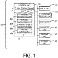
- FIG. 1 illustrates a configuration of a printing apparatus 10 according to the embodiment, in a simplified manner.
- the printing apparatus 10 performs a printing method.
- the printing apparatus 10 is provided with a control unit 11, a display unit 13, an operation receiving unit 14, an imaging unit 15, a transport unit 16, a printing unit 17, a storage unit 18, and the like.
- the control unit 11 is configured to include, as a processor, one or more ICs including a CPU 11a, a ROM 11b, a RAM 11c, and the like, another non-volatile memory, and the like.
- the processor that is, the CPU 11a executes arithmetic processing in accordance with one or more programs 12 stored in the ROM 11b, the other memory, or the like, using the RAM 11c or the like as a work area, to control the printing apparatus 10.
- the control unit 11 functions, in accordance with the program 12, as a pattern registration unit 12a, a pattern extracting unit 12b, a printing image generation unit 12c, a printing control unit 12d, and the like.
- the processor is not limited to the single CPU, and a configuration may be adopted in which the processing is performed by a hardware circuit such as a plurality of CPUs, an ASIC, or the like, or a configuration may be adopted in which the CPU and the hardware circuit work in concert to perform the processing.
- the display unit 13 is a device for displaying visual information, and is configured, for example, by a liquid crystal display, an organic EL display, or the like.
- the display unit 13 may be configured to include a display and a drive circuit for driving the display.
- the operation receiving unit 14 is a device for receiving an operation by a user, and is realized, for example, by a physical button, a touch panel, a mouse, a keyboard, or the like. Of course, the touch panel may be realized as a function of the display unit 13.
- the display unit 13 and the operation receiving unit 14 may be part of the configuration of the printing apparatus 10, or may be peripheral devices externally coupled to the printing apparatus 10.
- the transport unit 16 is a mechanism for transporting a printing medium under control by the control unit 11.
- a fabric is assumed, as the printing medium, formed with a stereoscopic pattern by devising a weaving method of yarns and fibers, such as a jacquard woven fabric or a lace fabric.
- a certain pattern or a set of certain patterns are formed so as to be aligned repeatedly.
- a pattern or a set of patterns will be treated as one pattern.
- the transport unit 16 includes, for example, a feeding roller for feeding a fabric before printing, which is wound in a roll shape, to downstream of transport, a belt or roller for further transporting the fabric fed, a winding roller for winding the fabric after the printing in a roll shape and collecting the fabric, a motor for rotating each roller or belt, or the like.
- a feeding roller for feeding a fabric before printing, which is wound in a roll shape, to downstream of transport
- a belt or roller for further transporting the fabric fed
- a winding roller for winding the fabric after the printing in a roll shape and collecting the fabric
- a motor for rotating each roller or belt or the like.
- the imaging unit 15 images the fabric transported by the transport unit 16 under control by the control unit 11.
- the imaging unit 15 has a configuration such as a light source that irradiates the fabric, an imaging element that receives reflected light from the fabric, and generates and outputs image data as an imaging result, or the like.
- the printing unit 17 performs printing on the fabric transported by the transport unit 16 under control by the control unit 11.
- the printing unit 17 is provided downstream from the imaging unit 15.
- the printing unit 17 performs printing on the fabric based on printing image data transmitted from the control unit 11.
- the printing unit 17 can perform printing by discharging ink of a plurality of colors such as cyan, magenta, yellow, and black, for example, by an ink-jet method.
- the printing unit 17 performs printing on the fabric by discharging dots of ink from a nozzle (not illustrated) based on printing image data defining dot on or dot off of each ink for each pixel.
- the storage unit 18 is a storage method such as a non-volatile memory or a hard disk drive.
- the storage unit 18 may be interpreted as a part of the control unit 11. Additionally, the RAM 11c may be interpreted as a part of the storage unit 18.
- the printing apparatus 10 may be referred to as a recording device, an image forming device, a printer, or the like.
- the printing apparatus 10 may be realized not only by a single independent device, but also by a plurality of devices communicatively coupled to each other via a communication interface or a network.
- the printing apparatus 10 configured by a plurality of devices may be referred to as a printing system 10.
- the printing system 10 is configured to include, for example, a printer including the imaging unit 15, the transport unit 16, and the printing unit 17, and one or more information processing devices that function as the control unit 11.
- the information processing device is, for example, a personal computer (PC), a server, a smart phone, a tablet terminal, or a device having the same degree of processing capability as those devices.
- a device serving as the control unit 11 may be referred to as an image processing apparatus, a printing control device, or the like.
- some devices that configure the printing system 10 may be considered as an invention.
- FIG. 2A illustrates a configuration of a fabric 30 to be transported and a vicinity of the fabric 30 in a perspective facing downward from above.
- a depiction of a preformed pattern in the fabric 30 is omitted.
- a transport direction of the fabric 30 by the transport unit 16 is denoted by a reference sign D1.
- a reference sign 22 denotes an endless belt 22 as a portion of the transport unit 16. The fabric 30 in a state of being placed on the endless belt 22 is transported from upstream to downstream by the endless belt 22 rotating.
- a carriage 20 is arranged above the endless belt 22.
- the carriage 20 can reciprocate along a direction D2 that intersects the transport direction D1. Although the intersection here is orthogonal, it may be understood that orthogonal includes not only strict orthogonality, but also errors that occur in product manufacturing.
- the carriage 20 moves along an elongated guide member 21 in the direction D2.
- the direction D2 is also referred to as a main scanning direction of the carriage 20 and a printing head 19.
- the direction D2 is also referred to as a width direction of the fabric 30.
- the carriage 20 is equipped with the printing head 19. That is, the printing head 19 reciprocates along the width direction D2 with the carriage 20. Such a carriage 20 and a printing head 19 configure the printing unit 17. Although not illustrated, a plurality of nozzles open on a lower surface opposite the endless belt 22 in the printing head 19. The printing head 19 discharges ink from the nozzle based on printing image data while moving along the width direction D2 with the carriage 20.
- the imaging unit 15 is arranged above the endless belt 22 at a predetermined position upstream of the carriage 20 and the printing head 19.
- FIG. 2B illustrates a part of the configuration illustrated in FIG. 2A in a perspective facing downstream from upstream.
- the imaging unit 15 has a lower surface opposite the endless belt 22 as an imaging surface 15a, and images the fabric 30 above the endless belt 22 via the imaging surface 15a.
- the imaging unit 15 is, for example, a line scan type camera in which a plurality of imaging elements are arranged inside thereof in the width direction D2.
- the imaging unit 15 repeats imaging on a line-by-line basis via a lens (not illustrated) and the imaging element provided at the imaging surface 15a.
- an imaging range in the width direction D2 by the imaging unit 15 is illustrated by dashed lines.
- the imaging unit 15 is capable of imaging approximately an entire range of the endless belt 22 in the width direction D2 by a function of the lens.
- the configuration of the imaging unit 15 is not limited to the example of FIGS. 2A and 2B .
- a configuration may be adopted in which a plurality of the imaging units 15 are arranged above the endless belt 22 along the width direction D2, and each of the plurality of imaging units 15 takes charge of a partial range of the entire range of the endless belt 22 in the width direction D2 and performs imaging.
- the imaging unit 15 may be a line sensor configured by arranging the plurality of imaging elements over approximately the entire range of the endless belt 22 in the width direction D2.
- the imaging unit 15 may be configured to be mounted on a carriage that can move along the width direction D2, and to image above the endless belt 22 while moving in the width direction D2 by the carriage.
- FIG. 3 illustrates, by a flowchart, printing processing that the control unit 11 performs in accordance with the program 12.
- step S100 the pattern registration unit 12a of the control unit 11 registers pattern image data representing a pattern formed in the fabric 30 with the storage unit 18.
- the pattern image data corresponds to "first image data”
- step S100 corresponds to a registration step.
- FIG. 4 illustrates details of step S100 by a flowchart.
- the pattern registration unit 12a acquires base image data representing the pattern in the fabric 30.
- the fabric 30 is a woven fabric in which, for example, one pattern designed by a designer is woven repeatedly. Therefore, it is assumed that the base image data is image data representing the one pattern that is generated in advance using predetermined software for design or drawing.
- the pattern registration unit 12a is input with base image data stored in a PC from the PC external to the printing apparatus 10, for example, in accordance with a user operation, and stores the input base image data in the storage unit 18.
- the pattern registration unit 12a acquires pre-scan data, which is image data generated by pre-scan of the fabric 30.
- the pre-scan means reading or imaging that is performed before imaging of the fabric 30 to be started in step S110 described below.
- a user causes a scanner external to the printing apparatus 10 to scan the fabric 30 in advance.
- the pattern registration unit 12a is input with image data generated by this scan from the scanner, and stores the image data as pre-scan data in the storage unit 18.
- the pre-scan may be performed by the imaging unit 15.
- the control unit 11 causes the transport unit 16 to start transporting the fabric 30, and causes the transport of the fabric 30 to stop at timing at which a tip of the fabric 30 reaches a position, which is downstream from the imaging unit 15 by a predetermined distance.
- the tip of the fabric 30 is an end portion facing downstream of the fabric 30.
- the imaging unit 15 images the fabric 30 passing by transporting under the imaging unit 15, and the pattern registration unit 12a is input with image data generated by this imaging from the imaging unit 15 and stores the image data as pre-scan data in the storage unit 18.
- step S106 the pattern registration unit 12a compares the base image data acquired in step S102 with the pre-scan data acquired in step S104 to extract, in the pre-scan data, a pattern region corresponding to one pattern of the fabric 30.
- the pattern registration unit 12a uses an image recognition technology to extract an image region with higher similarity with the base image data in the pre-scan data, and uses this image region as the pattern region.
- step S108 the pattern registration unit 12a stores image data corresponding to the pattern region extracted in step S106 in the storage unit 18 as pattern image data. As a result, the pattern image data is registered.
- the pattern image data can be said to be at least a part of the pre-scan data.
- the pattern registration unit 12a may simplify a part of step S100 by registering base image data itself with the storage unit 18 as pattern image data.
- step S109 the pattern registration unit 12a divides the pattern image data in at least one of a vertical direction and a horizontal direction, and registers N divided pieces of pattern image data with the storage unit 18.
- N is an integer of 2 or greater.
- the divided pattern image data corresponds to "divided first image data". In this way, step S100 is completed.
- an orientation of each image data such as pattern image data, imaging data, and printing image data handled by the control unit 11 will also be described corresponding to the transport direction D1 and the width direction D2.
- the transport direction D1 is the vertical direction
- the width direction D2 is the horizontal direction.
- the number of divisions of the pattern image data in each of the vertical direction and the horizontal direction is predetermined.
- the pattern registration unit 12a may acquire the number of divisions in each of the vertical direction and the horizontal direction through an operation of the operation receiving unit 14 by the user, and perform step S109. Note that, instead of storing the N divided pieces of pattern image data in step S109, the pattern registration unit 12a may store position information of the N divided pieces of pattern image data in the pattern image data.
- step S110 the control unit 11 causes the imaging unit 15 to start imaging with the fabric 30 as a target that the transport unit 16 transports at predetermined velocity. That is, in step S110, a "transport step” of the fabric 30 is started. In addition, an “imaging step” is started by step S110. Image data on a line-by-line basis generated by the imaging of the fabric 30 by the imaging unit 15 is sequentially output to the control unit 11. The control unit 11 acquires two-dimensional imaging data, by sequentially storing the image data on a line-by-line basis from the imaging unit 15. The imaging data corresponds to "second image data".
- step S120 the pattern extracting unit 12b, based on a comparison between the pattern image data registered in step S100 and the imaging data generated by the imaging in step S110, extracts a pattern region corresponding to the pattern in the fabric 30 in the imaging data.
- the imaging data a plurality of the patterns are represented side by side.
- Step S120 corresponds to a "pattern extraction step".
- FIG. 5 illustrates details of step S120 by a flowchart.
- n a number of the divided pattern image data
- step S122 the pattern extracting unit 12b increments n. That is, 1 is added to n, which is current, to update n.
- step S123 the pattern extracting unit 12b sets the n-th divided pattern image data to a reference of extraction.
- step S124 the pattern extracting unit 12b compares the divided pattern image data set as the reference of extraction with the imaging data, to extract, from the imaging data, a partial pattern region corresponding to a partial pattern represented by the divided pattern image data as the reference.
- the pattern extracting unit 12b uses an image recognition technology to extract, as a partial pattern region, an image region having a degree of similarity with the divided pattern image data that is higher than a predetermined level. Specifically, the pattern extracting unit 12b extracts an edge of an image in the divided pattern image data, and similarly extracts an edge of an image in the imaging data. Then, an edge distribution in the divided pattern image data is repeatedly compared with an edge distribution in the imaging data, while a position is shifted, and while the divided pattern image data is deformed, and a region in which a degree of match between the edge distributions is highly evaluated above a predetermined level is extracted as one partial pattern region. With such a process, the pattern extracting unit 12b extracts the partial pattern region from inside the imaging data. Note that, as in the process in step S124, in step S106 described above, the pattern registration unit 12a can extract a pattern region in pre-scan data according to a degree of match of edge distributions between images to be compared.
- step S125 the pattern extracting unit 12b outputs information of the partial pattern region extracted by step S124 to the printing image generation unit 12c for step S130 and subsequent steps.
- the width direction D2 is taken as an X-axis
- the transport direction D1 is taken as a Y-axis
- coordinates of imaging data are defined in a two-dimensional plane according to the orthogonal X- and Y-axes.
- the process of extracting a partial pattern region from imaging data is a process of identifying coordinates of the partial pattern region in the imaging data.
- the coordinates of the partial pattern region are, for example, center coordinates or coordinates of four corners of the partial pattern region. Accordingly, in step S125, it is sufficient that the pattern extracting unit 12b outputs the information of the coordinates of the partial pattern region.
- the pattern extracting unit 12b repeats step S122 and the subsequent steps after determining "No" in step S126.
- the pattern extracting unit 12b repeats step S124 N times while setting the first to N-th divided pattern image data to the reference of extraction sequentially one by one according to the flow.
- the pattern extracting unit 12b may perform extraction of the N types of partial pattern regions performed with the first to N-th divided pattern image data each being the reference of extraction, in parallel in step S120.
- a reference sign 40 denotes pattern image data 40.
- the pattern image data 40 is image data that represents a pattern designed with a petal shape as a motif. Of course, such a pattern may be more complex.
- FIG. 6 illustrates a part of imaging data 42.
- a pattern similar to the pattern represented by the pattern image data 40 is repeatedly represented along each of the transport direction D1 and the width direction D2.
- Each rectangle indicated by solid lines in the imaging data 42 is a partial pattern region 41a corresponding to a partial pattern represented by the divided pattern image data 40a.
- the pattern extracting unit 12b extracts the partial pattern region 41a similar to the divided pattern image data 40a from a plurality of locations in the imaging data 42.
- each rectangle indicated by dashed lines in the imaging data 42 is a partial pattern region 41b corresponding to a partial pattern represented by the divided pattern image data 40b.
- the pattern extracting unit 12b extracts the partial pattern region 41b similar to the divided pattern image data 40b from a plurality of locations in the imaging data 42.
- a rectangle indicated by dot-dash lines in the imaging data 42 is one of partial pattern regions 41c corresponding to the divided pattern image data 40c
- a rectangle indicated by two-dot chain lines in the imaging data 42 is one of partial pattern regions 41d corresponding to the divided pattern image data 40d.
- the partial pattern region 41c and the partial pattern region 41d are also extracted from a plurality of locations in the imaging data 42.
- a set of the partial pattern regions 41a, 41b, 41c, and 41d form one pattern region 41.
- the process of comparing each of the plurality of divided pieces of pattern image data 40a, 40b, 40c, and 40d constituting the pattern image data 40 with the imaging data 42 to extract the partial pattern regions 41a, 41b, 41c, and 41d by the pattern extracting unit 12b corresponds to a process of extracting the pattern regions 41 from the imaging data 42.
- step S130 the printing image generation unit 12c corrects colored image data that represents an image to be printed overlaid on the pattern in the fabric 30 so as to match a shape of the pattern region extracted in step S120.
- the colored image data corresponds to "third image data".
- the colored image data is pre-generated color image data representing a color to color one pattern, or a print range of a color.
- the colored image data is stored in advance in the storage unit 18, for example.
- the control unit 11 is input with colored image data stored in a PC from the PC external to the printing apparatus 10, for example, in accordance with a user operation, and stores the input colored image data in the storage unit 18.
- a shape of the colored image data is an ideal shape of a pattern region having one pattern, for example, a rectangle.
- a shape of each pattern region extracted from the imaging data in step S120 is basically a square, but does not necessarily match the shape of the colored image data. This is because distortion, expansion and contraction (hereinafter, distortion, and the like) may be generated in the fabric 30 being transported.
- each of the partial pattern regions 41a, 41b, 41c, and 41d that constitute each of the pattern regions 41 extracted from the imaging data 42 may have a shape that is distorted, expanded, or contracted due to distortion and the like in the fabric 30.
- the printing image generation unit 12c deforms each of the plurality of divided pieces of colored image data obtained by dividing the colored image data in at least one of the vertical direction and the horizontal direction so as to match an individual shape of the partial pattern region extracted in step S120.
- the divided colored image data corresponds to "divided third image data".
- the printing image generation unit 12c divides the colored image data to acquire N divided pieces of colored image data, by the same division aspect for dividing the pattern image data to acquire the N divided pieces of pattern image data in step S109 by the pattern registration unit 12a.
- the printing image generation unit 12c similarly divides the colored image data into three equal portions in the vertical direction and into three equal portions in the horizontal direction to acquire nine divided pieces of colored image data.
- the printing image generation unit 12c deforms one divided piece of colored image data so as to match a shape of a partial pattern region in which a position in the pattern region corresponds to a position of the divided colored image data in the colored image data.
- a deformation method for example, an affine transformation including expansion, contraction, rotation, shear, and the like of an image, or another deformation method is used.
- Such deformation is a correction by step S130. Note that, depending on the shape of the pattern region, the correction in step S130 is not necessary as a result in some cases.
- step S140 the printing image generation unit 12c arranges the plurality of divided pieces of colored image data after step S130 so as to correspond to an array of the partial pattern regions and the pattern regions in the imaging data to generate printing image data.
- the printing image data is image data in which the plurality of divided pieces of colored image data after step S130 are combined, and is an image printed on a region of the fabric 30 as a target of imaging.
- steps S130 and S140 correspond to a "printing image generation step" of arranging the third image data so as to match the pattern region extracted to generate the printing image data.
- a reference sign 50 denotes colored image data 50.
- the colored image data 50 is color image data representing colors to be colored overlaid on a pattern designed with a petal as a motif.
- the colored image data 50 may be interpreted as an image having the same or substantially the same size as the pattern image data 40 vertically and horizontally. Similar to the pattern image data 40, the colored image data 50 is divided into two equal portions in the transport direction D1 and divided into two equal portions in the width direction D2, to be divided into four divided pieces of colored image data 50a, 50b, 50c, and 50d.
- a reference sign 51a denotes divided colored image data 51a after correcting the divided colored image data 50a so as to match a shape of the partial pattern region 41a constituting one certain pattern region 41.
- a reference sign 51b denotes divided colored image data 51b after correcting the divided colored image data 50b so as to match a shape of the partial pattern region 41b constituting the one pattern region 41.
- a reference sign 51c is divided colored image data 51c after correcting the divided colored image data 50c so as to match a shape of the partial pattern region 41c constituting the one pattern region 41.
- a reference sign 51d is divided colored image data 51d after correcting the divided colored image data 50d so as to match a shape of the partial pattern region 41d constituting the one pattern region 41.
- step S130 the printing image generation unit 12c repeatedly performs the correction of the divided colored image data 50a, 50b, 50c, and 50d for each of the pattern regions 41 constituted by the partial pattern regions 41a, 41b, 41c, and 41d extracted in step S120.
- the divided colored image data 51a, 51b, 51c, and 51d after such a correction combined according to a positional relationship among the partial pattern regions 41a, 41b, 41c, and 41d in the pattern region 41, and an array of the pattern regions 41 in the imaging data 42, form printing image data 52.
- the control unit 11 after starting imaging of the fabric 30 in step S110, repeats steps S120 to S140 in accordance with the imaging data obtained sequentially from the imaging unit 15.
- the control unit 11 performs step S120 using imaging data of a predetermined size obtained sequentially from the imaging unit 15 as a target, and performs steps S130 and S140 in response to a result of step S120.
- the printing image data 52 illustrated in FIG. 7 is the printing image data obtained as a result of one cycle of such steps S120 to S140.
- step S150 the printing control unit 12d starts printing of the printing image data generated in step S140 on the fabric 30.
- a "printing step” is started by step S150.
- the printing image generation unit 12c sequentially generates printing image data by repeating step S140, and outputs the printing image data sequentially to the printing control unit 12d in an order of generation.
- the printing control unit 12d appropriately performs various types of necessary processing such as so-called color conversion processing and halftone processing on the printing image data acquired from the printing image generation unit 12c, to convert the printing image data into printing image data in a format used by the printing unit 17 for printing.
- the printing control unit 12d may temporarily accumulate the printing image data after such conversion in a buffer.
- the printing control unit 12d transfers the printing image data after the above conversion to the printing unit 17, and causes the printing unit 17 to start printing by movement of the carriage 20 and ink discharge from the printing head 19 based on the printing image data at predetermined timing at which a position of the fabric 30 for which imaging is started by step S110 reaches below the printing head 19.
- color images represented by the individual colored image data constituting the printing image data are printed overlaid on the pattern in a shape that matches the individual pattern in the fabric 30.
- the transport unit 16 is provided with an encoder that detects an amount of rotation of rollers and belts rotating for transport.
- the printing control unit 12d computes a transport distance of the fabric 30 in accordance with a detection signal from the encoder. Accordingly, the printing control unit 12d can grasp a current position in the transport direction D1 of the fabric 30 for which imaging is started by step S110, and can cause the printing unit 17 to start printing on the fabric 30 at timing at which the position reaches below the printing head 19.
- control unit 11 determines whether to end the printing or not (step S160). When ending the printing, the control unit 11 determines "Yes" and proceeds to an end process in step S170. The control unit 11 determines to end the printing when, for example, the end of printing is instructed by a user, or when the transport of the fabric 30 by a predetermined length is completed.
- control unit 11 stops imaging of the fabric 30 by the imaging unit 15. In addition, the control unit 11 stops driving the transport unit 16 and the printing unit 17 after causing the printing unit 17 to perform printing based on the printing image data generated in one cycle of the last steps S120 to S140, and ends the flowchart in FIG. 3 .
- control unit 11 may stop the transport unit 16 after controlling a necessary process such as collection of the fabric 30 by a winding roller.
- the pattern extracting unit 12b extracts a partial pattern region by a comparison with imaging data in units of divided pattern image data.
- a plurality of similar partial patterns are included in one pattern, and when one certain divided piece of pattern image data is set to a reference of extraction in step S123, and step S124 is performed, there is a possibility that any of the partial patterns at the plurality of locations is extracted as a partial pattern region.
- a partial pattern region at one location is to be extracted originally based on one divided piece of pattern image data.
- the pattern extracting unit 12b may calculate accuracy of extraction of the partial pattern region in step S120, and select information of the partial pattern region required for processes in step S130 and subsequent steps.
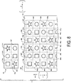
- FIG. 8 illustrates an example of pattern image data and imaging data different from FIG. 6 .
- a reference sign 43 denotes pattern image data 43 representing one pattern.
- partial patterns represented by the divided pattern image data 43a, 43b, 43c, 43d, 43e, and 43f respectively are simplified, and drawn by using a square pattern " ⁇ ", a circle pattern " ⁇ ", or a star pattern " ⁇ ".
- the partial pattern represented by the divided pattern image data 43a, and the partial pattern represented by the divided pattern image data 43e are similar to each other.
- the partial pattern represented by the divided pattern image data 43b and the partial pattern represented by the divided pattern image data 43f are similar to each other.
- the partial pattern represented by the divided pattern image data 43c and the partial pattern represented by the divided pattern image data 43d are similar to each other.
- FIG. 8 illustrates a part of the imaging data 45.
- a pattern similar to the pattern represented by the pattern image data 43 is repeatedly represented along each of the transport direction D1 and the width direction D2. Rectangles indicated by broken lines in the imaging data 45 are partial pattern regions 44a, 44b, 44c, 44d, 44e, 44f, 44g, 44h, 44i, 44j, 44k, 44l, 44m, 44n, 44o, 44p, 44q, 44r, 44s, 44t, 44u, 44v, 44w, 44x, and the like, extracted by step S124 in FIG. 5 .
- step S124 is performed by setting the divided pattern image data 43a to a reference of extraction in step S123
- the pattern extracting unit 12b extracts the partial pattern regions 44a, 44d, 44h, 44k, 44m, 44p, 44t, and 44w, according to the example in FIG. 8 .
- a partial pattern region to be extracted when the divided pattern image data 43e instead of the divided pattern image data 43a is set to the reference of extraction is also included.
- the pattern extracting unit 12b calculates accuracy of extraction for each partial pattern region extracted in step S124, based on a comparison between a positional relationship between this partial pattern region and other partial pattern regions extracted in a periphery, and a positional relationship among a plurality of divided pieces of pattern image data in the pattern image data.
- the accuracy of extraction is also referred to as "extraction accuracy”.
- Each of a plurality of partial pattern regions extracted from a plurality of positions of imaging data corresponding to a partial pattern represented by one certain divided piece of pattern image data corresponds to "first partial pattern region".
- each of the partial pattern regions 44a and 44h is the first partial pattern region.
- the square pattern " ⁇ " is a partial pattern region extracted when the divided pattern image data 43a or the divided pattern image data 43e is set to the reference of extraction.
- the width direction D2 is taken as an X-axis + direction
- a reverse direction of the width direction D2 is taken as an X-axis - direction
- an upstream direction in the transport direction D1 is taken as a Y-axis + direction
- a downstream direction in the transport direction D1 is taken as a Y axis - direction.
- the extraction accuracy of the partial pattern region 44a is calculated.
- a partial pattern region next to the partial pattern region 44a in the X-axis + direction is to correspond to the circle pattern " ⁇ " in the imaging data 45.
- the circle pattern " ⁇ " is a partial pattern region extracted when the divided pattern image data 43b or the divided pattern image data 43f is set to the reference of extraction.
- the pattern extracting unit 12b sets the extraction accuracy of the partial pattern region 44a to +1 in accordance with this fact.
- a partial pattern region two ahead from the partial pattern region 44a in the X-axis + direction is to correspond to the star pattern " ⁇ ".
- the star pattern " ⁇ " is a partial pattern region extracted when the divided pattern image data 43c or the divided pattern image data 43d is set to the reference of extraction.
- the partial pattern region 44c being the star pattern " ⁇ " is extracted two ahead from the partial pattern region 44a in the X-axis + direction, thus the pattern extracting unit 12b adds +1 to the extraction accuracy of the partial pattern region 44a.
- a partial pattern region next to the partial pattern region 44a in the Y-axis + direction is to correspond to the star pattern " ⁇ "
- the partial pattern region 44g being the star pattern " ⁇ ” is extracted next to the partial pattern region 44a in the Y-axis + direction.
- the pattern extracting unit 12b adds +1 to the extraction accuracy of the partial pattern region 44a.
- a partial pattern region one ahead in the X-axis + direction and one ahead in the Y-axis + direction from the partial pattern region 44a is to correspond to the square pattern " ⁇ "
- the partial pattern region 44h being the square pattern " ⁇ ” is extracted one ahead in the X-axis + direction and one ahead in the Y-axis + direction from the partial pattern region 44a.
- the pattern extracting unit 12b adds +1 to the extraction accuracy of the partial pattern region 44a.
- a partial pattern region two ahead in the X-axis + direction and one ahead in the Y-axis + direction from the partial pattern region 44a is to correspond to the circle pattern " ⁇ "
- the partial pattern region 44i being the circle pattern " ⁇ ” is extracted two ahead in the X-axis + direction and one ahead in the Y-axis + direction from the partial pattern region 44a.
- the pattern extracting unit 12b adds +1 to the extraction accuracy of the partial pattern region 44a.
- the pattern extracting unit 12b calculates the extraction accuracy as "+5" for the partial pattern region 44a extracted from the imaging data 45 with the divided pattern image data 43a as the reference of extraction. Note that, in the situation in which the pattern image data 43 is divided into six as illustrated in FIG. 8 , the extraction accuracy "+5" refers to the highest point of the accuracy of extraction.
- extraction accuracy of the partial pattern region 44h is calculated.
- a partial pattern region next to the partial pattern region 44h in the X-axis + direction is to correspond to the circle pattern " ⁇ " in the imaging data 45, and the partial pattern region 44i being the circle pattern " ⁇ " is extracted next to the partial pattern region 44h in the X-axis + direction. Therefore, the pattern extracting unit 12b sets the extraction accuracy of the partial pattern region 44h to +1.
- the partial pattern region 44j being the star pattern " ⁇ " is extracted two ahead in the X-axis + direction from the partial pattern region 44h.
- the pattern extracting unit 12b adds +1 to extraction accuracy of the partial pattern region 44h.
- the pattern extracting unit 12b does not add points to the extraction accuracy of the partial pattern region 44h.
- a partial pattern region one ahead in the X-axis + direction and one ahead in the Y-axis + direction from the partial pattern region 44h is to correspond to the square pattern " ⁇ "
- the partial pattern region 44o being the star pattern " ⁇ ” is extracted one ahead in the X-axis + direction and one ahead in the Y-axis + direction from the partial pattern region 44h. Based on this fact, the pattern extracting unit 12b does not add points to the extraction accuracy of the partial pattern region 44h.
- a partial pattern region two ahead in the X-axis + direction and one ahead in the Y-axis + direction from the partial pattern region 44h is to correspond to the circle pattern " ⁇ "
- the partial pattern region 44p being the square pattern " ⁇ ” is extracted two ahead in the X-axis + direction and one ahead in the Y-axis + direction from the partial pattern region 44h. Based on this fact, the pattern extracting unit 12b does not add points to the extraction accuracy of the partial pattern region 44h.
- the pattern extracting unit 12b calculates the extraction accuracy as "+2" for the partial pattern region 44h extracted from the imaging data 45 with the divided pattern image data 43a as the reference of extraction.
- the partial pattern region 44a and the partial pattern region 44h can be extracted from the imaging data 45 with the divided pattern image data 43a as the reference of extraction, due to a difference in extraction accuracy, it is understood that the partial pattern region 44a is a correct extraction result, and the partial pattern region 44h is an erroneous extraction result, as an extraction result based on the divided pattern image data 43a.
- the extraction accuracy of the partial pattern region 44b is calculated.
- a partial pattern region next to the partial pattern region 44b in the X-axis - direction in the imaging data 45 is to correspond to the square pattern " ⁇ "
- the partial pattern region 44a being the square pattern " ⁇ ” is extracted next to the partial pattern region 44b in the X-axis - direction. Therefore, the pattern extracting unit 12b sets the extraction accuracy of the partial pattern region 44b to +1.
- the partial pattern region 44c being the star pattern " ⁇ ” is extracted next to the partial pattern region 44b in the X-axis + direction, thus the pattern extracting unit 12b adds +1 to the extraction accuracy of the partial pattern region 44b.
- the partial pattern region 44g being the star pattern " ⁇ ” is extracted one ahead in the X-axis - direction and one ahead in the Y-axis + direction from the partial pattern region 44b, thus the pattern extracting unit 12b adds +1 to the extraction accuracy of the partial pattern region 44b.
- the partial pattern region 44h being the square pattern " ⁇ ” is extracted next to the partial pattern region 44b in the Y-axis + direction, thus the pattern extracting unit 12b adds +1 to the extraction accuracy of the partial pattern region 44b.
- the partial pattern region 44i being the circle pattern " ⁇ ” is extracted one ahead in the X-axis + direction and one ahead in the Y-axis + direction from the partial pattern region 44b, thus the pattern extracting unit 12b adds +1 to the extraction accuracy of the partial pattern region 44b. Accordingly, the pattern extracting unit 12b calculates the extraction accuracy as "+5" for the partial pattern region 44b extracted from the imaging data 45 with the divided pattern image data 43b as the reference of extraction.
- the extraction accuracy of the partial pattern region 44i is calculated.
- the partial pattern region 44h being the square pattern " ⁇ " is extracted next to the partial pattern region 44i in the X axis - direction. Therefore, the pattern extracting unit 12b sets the extraction accuracy of the partial pattern region 44i to +1.
- the partial pattern region 44j being the star pattern " ⁇ " is extracted next to the partial pattern region 44i in the X-axis + direction, thus the pattern extracting unit 12b adds +1 to the extraction accuracy of the partial pattern region 44i.
- the pattern extracting unit 12b does not add points to the extraction accuracy of the partial pattern region 44i, based on this fact. Furthermore, because the partial pattern region 44o next to the partial pattern region 44i in the Y-axis + direction is not the square pattern " ⁇ ", the pattern extracting unit 12b does not add points to the extraction accuracy of the partial pattern region 44i, based on this fact.
- the pattern extracting unit 12b calculates the extraction accuracy as "+2" for the partial pattern region 44i extracted from the imaging data 45 with the divided pattern image data 43b as the reference of extraction.
- the partial pattern region 44b and the partial pattern region 44i can be extracted from the imaging data 45 with the divided pattern image data 43b as the reference of extraction, it is understood that, due to a difference in extraction accuracy, the partial pattern region 44b is a correct extraction result, and the partial pattern region 44i is an erroneous extraction result, as an extraction result based on the divided pattern image data 43b.
- FIG. 9 shows, in a table format, extraction accuracy for each combination of the divided pattern image data as the reference of extraction, and partial pattern region extracted from the imaging data based on the divided pattern image data as the reference of extraction.
- the pattern extracting unit 12b calculates, for each partial pattern region extracted, extraction accuracy from a positional relationship with surrounding partial pattern regions as described above.
- the partial pattern region 44a may be extracted in both a case with the divided pattern image data 43a as a reference of extraction, and a case with the divided pattern image data 43e as a reference of extraction.
- the extraction accuracy with the divided pattern image data 43a as the reference of extraction is "+5", and the extraction accuracy with the divided pattern image data 43e as the reference of extraction is "+1", thus it is understood that the partial pattern region 44a extracted with the divided pattern image data 43a as the reference is a correct extraction result, and the partial pattern region 44a extracted with the divided pattern image data 43e as the reference is an erroneous extraction result.
- the pattern extracting unit 12b performs calculation of such extraction accuracy at the timing of step S125, and, for example, when the extraction accuracy as illustrated in FIG. 9 is obtained, the pattern extracting unit 12b selects a partial pattern region having extraction accuracy of "+5", and outputs information of the selected partial pattern region to the printing image generation unit 12c as an extraction result.
- the pattern extracting unit 12b selects, out of the partial pattern regions extracted in step S124, a partial pattern region for which calculated extraction accuracy is equal to or greater than a predetermined threshold value, and outputs information of the selected partial pattern region to the printing image generation unit 12c as an extraction result.
- the pattern extracting unit 12b provides an extraction result of a first partial pattern region having relatively high extraction accuracy among first partial pattern regions at a plurality of positions, to the printing image generation unit 12c for generation of printing image data.
- the pattern extracting unit 12b repeats steps S122, S123, and S124 a plurality of times, and for example as illustrated in FIG. 8 , at timing after extraction of a partial pattern region of the imaging data 45 using consecutive predetermined sized regions as a target has ended, calculates extraction accuracy for each partial pattern region, and selects a partial pattern region based on the extraction accuracy, in step S125.
- the calculation of the extraction accuracy is possible even in a situation in which a group having a plurality of partial pattern regions corresponding to one pattern image data cannot be extracted. It is assumed that, due to velocity at which the imaging data 45 is generated, the pattern extracting unit 12b has not acquire a part of the imaging data 45 having the partial pattern regions 44s, 44t, 44u, 44v, 44w, and 44x, at the time of step S120. Even in such a case, the pattern extracting unit 12b calculates, for example, extraction accuracy of the partial pattern region 44m from a relationship with the partial pattern region 44n or the partial pattern region 44o.
- the pattern extracting unit 12b uses, as a parameter, the number of other partial pattern regions referred to in order to calculate the extraction accuracy of the partial pattern region 44m, and uses, as extraction accuracy, a ratio of the number of the partial pattern regions for which a positional relationship with the partial pattern region 44m coincides with a positional relationship of divided pattern image data in the pattern image data 43.
- the extraction accuracy is set to 2/2, that is, the extraction accuracy set to 100%.
- the pattern extracting unit 12b selects a partial pattern region with a certain degree of extraction accuracy, using a threshold, for example.
- the printing apparatus 10 includes the transport unit 16 configured to transport the fabric 30 formed with a pattern in the transport direction D1, the imaging unit 15 configured to image the fabric 30 transported by the transport unit 16, the printing unit 17 configured to perform printing on the fabric 30 transported by the transport unit 16, the pattern extracting unit 12b configured to, based on a comparison between first image data representing the pattern, and second image data generated by imaging the fabric 30 by the imaging unit 15, extract a pattern region corresponding to the pattern in the second image data, the printing image generation unit 12c configured to arrange third image data representing an image to be printed overlaid on the pattern so that the third image data matches the pattern region extracted to generate printing image data, and the printing control unit 12d configured to cause the printing unit 17 to print the printing image data on the fabric 30.
- the pattern extracting unit 12b compares each of a plurality of divided pieces of first image data obtained by dividing the first image data in at least one of a vertical direction and a horizontal direction with the second image data, to extract, from the second image data, a partial pattern region corresponding to a partial pattern represented by the divided first image data.
- the printing image generation unit 12c arranges each of a plurality of divided pieces of third image data obtained by dividing the third image data in at least one of the vertical direction and the horizontal direction in accordance with the partial pattern region extracted to generate the printing image data.
- the pattern extracting unit 12b performs comparison with the second image data not in units of the first image data, but in units of the divided first image data, to extract the partial pattern region from the second image data.
- the printing image generation unit 12c arranges the divided third image data in units of the divided third image data so as to correspond to the partial pattern region to generate the printing image data.
- the third image data is arranged in units of the third image data so as to match a pattern region to perform printing, a fine adjustment and correction are easy to achieve, and a shift between the pattern and the image to be printed overlaid on the pattern is easily reduced.
- a distance between the imaging unit 15 and the printing head 19 in the transport direction D1 is determined according to product standards.
- each pattern formed in the fabric 30 is large, and the printing image data is generated after the pattern region corresponding to one pattern is extracted from the second image data, it is too late to start printing on the fabric 30, thus there is a need to reduce transport velocity of the fabric 30, or to suspend the transport.
- the partial pattern region is extracted from the second image data in units of the divided first image data, so as to match the partial pattern region in units of the divided third image data, to generate the printing image data.
- the printing image data can be generated sequentially without waiting one entire pattern being imaged or an entire pattern region being extracted, and a decrease in printing efficiency can be avoided.
- the present exemplary embodiment includes a configuration in which the pattern extracting unit 12b treats divided first image data obtained by dividing first image data only in a vertical direction, and the printing image generation unit 12c treats divided third image data by dividing third image data only in the vertical direction.
- the present exemplary embodiment includes a configuration in which the pattern extracting unit 12b treats divided first image data obtained by dividing first image data only in a horizontal direction, and the printing image generation unit 12c treats divided third image data by dividing third image data only in the horizontal direction.
- the pattern extracting unit 12b when extracting first partial pattern region corresponding to a partial pattern represented by one divided piece of first image data from a plurality of positions of the second image data, calculates accuracy of extraction, for each of the first partial pattern regions at the plurality of positions, based on a comparison between a positional relationship between the first partial pattern region and another partial pattern region extracted around the first partial pattern region, and a positional relationship among a plurality of the divided pieces of first image data in the first image data. Then, an extraction result of the first partial pattern region, where the accuracy is relatively high, among the first partial pattern regions at the plurality of positions, is provided to the printing image generation unit 12c for generation of printing image data.
- the pattern extracting unit 12b by calculating the accuracy of extraction, or extraction accuracy, on the partial pattern region, can eliminate the partial patterned region that was erroneously extracted from the second image data by a comparison with the divided first image data, and provide information of the partial pattern region extracted correctly for generation of printing image data.
- generation of printing image data by combining divided third image data with an erroneous arrangement can be avoided, and printing quality can be ensured.
- the present exemplary embodiment also discloses an invention of various categories, such as a system, a program, and a method other than the printing apparatus 10.
- a printing method includes a transport step for transporting the fabric 30 formed with a pattern in the transport direction D1, an imaging step for imaging the fabric 30 transported, a pattern extraction step for, based on a comparison between first image data representing the pattern and second image data generated by imaging the fabric 30 to extract a pattern region corresponding to the pattern in the second image data, a printing image generation step for arranging third image data representing an image to be printed overlaid on the pattern so that the third image data matches the pattern region extracted to generate printing image data, and a printing step for printing the printing image data on the fabric 30 transported.
- the pattern extraction step includes comparing each of a plurality of divided pieces of first image data obtained by dividing the first image data in at least one of a vertical direction and a horizontal direction with the second image data, to extract, from the second image data, a partial pattern region corresponding to a partial pattern represented by the divided first image data
- the printing image generation step includes arranging each of a plurality of divided pieces of third image data obtained by dividing the third image data in at least one of the vertical direction and the horizontal direction so as to match the partial pattern region extracted to generate the printing image data.
- the configuration of a so-called serial printer has been disclosed in which the printing head 19 is moved while being mounted on the carriage 20, but the printing head 19 may be a so-called line type head. That is, the printing head 19 may be an elongated printing head that is not mounted on the carriage 20 and that can cover a width of the fabric 30 along the width direction D2.
- the configuration denoted by the reference sign 22 need not be the endless belt, and may be a platen as a platform that supports the fabric 30 from below. That is, it may be understood that the fabric 30 transported by a roller (not illustrated) moves over the platen.
- the present exemplary embodiment can also be applied to a case where a material other than the fabric 30, for example, a paper printing medium, formed with a pattern is used for printing.
Landscapes
- Engineering & Computer Science (AREA)
- Physics & Mathematics (AREA)
- Theoretical Computer Science (AREA)
- General Physics & Mathematics (AREA)
- General Engineering & Computer Science (AREA)
- Computer Vision & Pattern Recognition (AREA)
- Multimedia (AREA)
- Mathematical Physics (AREA)
- Software Systems (AREA)
- Computing Systems (AREA)
- Databases & Information Systems (AREA)
- Evolutionary Computation (AREA)
- General Health & Medical Sciences (AREA)
- Medical Informatics (AREA)
- Artificial Intelligence (AREA)
- Health & Medical Sciences (AREA)
- Signal Processing (AREA)
- Textile Engineering (AREA)
- Treatment Of Fiber Materials (AREA)
- Record Information Processing For Printing (AREA)
- Ink Jet (AREA)
Abstract
Description
- The present application is based on, and claims priority from
JP Application Serial Number 2020-196817, filed November 27, 2020 - The present disclosure relates to a printing apparatus and a printing method.
- A technique has been known for searching an inspection target image for a candidate having similar characteristics to a model image obtained by imaging a good product serving as a model of the product (see
JP 2017-96750 A - Here, it is assumed that, when a fabric formed with a pattern is used as a printing medium, the pattern is extracted from a captured image obtained by imaging the fabric transported. Distortion, expansion and contraction (hereinafter, distortion, and the like) may be generated in the fabric being transported, and in a situation where such distortion and the like are present, a pattern needs to be extracted from a captured image, or a picture needs to be printed so as to match a pattern. However, when a size of one pattern formed in the fabric is relatively large, extraction accuracy of the pattern from the captured image is easily reduced, and a shift between the picture to be printed and the pattern is easily increased, due to effects of the distortion and the like.
- In addition, when the size of one pattern is large, each necessary process such as extracting the pattern from the captured image or generating data for printing cannot be completed within a limited time from capturing the fabric to starting printing in some cases. In this case, transport velocity of the fabric is reduced or the transport is temporarily stopped in order to wait for each necessary process to end, and thus efficiency of printing is reduced.
- There is a demand for a device for solving at least one of these problems.
- A printing apparatus includes a transport unit configured to transport a fabric formed with a pattern in a transport direction, an imaging unit configured to image the fabric transported by the transport unit, a printing unit configured to perform printing on the fabric transported by the transport unit, a pattern extracting unit configured to, based on a comparison between first image data representing the pattern and second image data generated by imaging the fabric by the imaging unit, extract a pattern region corresponding to the pattern in the second image data, a printing image generation unit configured to arrange third image data representing an image to be printed overlaid on the pattern so that the third image data matches the pattern region extracted to generate printing image data, and a printing control unit configured to cause the printing unit to print the printing image data on the fabric, wherein the pattern extracting unit compares each of a plurality of divided pieces of first image data obtained by dividing the first image data in at least one of a vertical direction and a horizontal direction with the second image data, to extract, from the second image data, a partial pattern region corresponding to a partial pattern represented by the divided first image data, and the printing image generation unit arranges each of a plurality of divided pieces of third image data obtained by dividing the third image data in at least one of the vertical direction and the horizontal direction, in accordance with the partial pattern region extracted, to generate the printing image data.
- A printing method includes a transport step for transporting a fabric formed with a pattern in a transport direction, an imaging step for imaging the fabric transported, a pattern extraction step for, based on a comparison between first image data representing the pattern and second image data generated by imaging the fabric, extracting a pattern region corresponding to the pattern in the second image data, a printing image generation step for arranging third image data representing an image to be printed overlaid on the pattern so that the third image data matches the pattern region extracted to generate printing image data, and a printing step for printing the printing image data on the fabric transported, wherein the pattern extraction step includes comparing each of a plurality of divided pieces of first image data obtained by dividing the first image data in at least one of a vertical direction and a horizontal direction with the second image data, to extract, from the second image data, a partial pattern region corresponding to a partial pattern represented by the divided first image data, and the printing image generation step includes arranging each of a plurality of divided pieces of third image data obtained by dividing the third image data in at least one of the vertical direction and the horizontal direction, in accordance with the partial pattern region extracted, to generate the printing image data.
-
-
FIG. 1 is a block diagram illustrating a configuration of a printing apparatus in a simplified manner. -
FIG. 2A is a view illustrating a configuration of a fabric to be transported and a vicinity thereof in a perspective facing downward from above, andFIG. 2B is a view illustrating a part of the configuration illustrated inFIG. 2A in a perspective facing downstream from upstream. -
FIG. 3 is a flowchart illustrating printing processing. -
FIG. 4 is a flowchart illustrating details of step S100. -
FIG. 5 is a flowchart illustrating details of step S120. -
FIG. 6 is a diagram for explaining step S120 by a specific example. -
FIG. 7 is a diagram for explaining steps S130 and S140 by a specific example. -
FIG. 8 is a diagram illustrating an example of pattern image data and imaging data different fromFIG. 6 . -
FIG. 9 is a diagram showing extraction accuracy of partial pattern regions in a table format. - Embodiments of the present disclosure will be described below with reference to the accompanying drawings. Note that each of the drawings is merely illustrative for describing the embodiment. Since the drawings are illustrative, proportions and shapes may not be precise, match each other, or some may be omitted.
-
FIG. 1 illustrates a configuration of aprinting apparatus 10 according to the embodiment, in a simplified manner. - The
printing apparatus 10 performs a printing method. Theprinting apparatus 10 is provided with acontrol unit 11, adisplay unit 13, anoperation receiving unit 14, animaging unit 15, atransport unit 16, aprinting unit 17, astorage unit 18, and the like. Thecontrol unit 11 is configured to include, as a processor, one or more ICs including aCPU 11a, aROM 11b, aRAM 11c, and the like, another non-volatile memory, and the like. - In the
control unit 11, the processor, that is, theCPU 11a executes arithmetic processing in accordance with one ormore programs 12 stored in theROM 11b, the other memory, or the like, using theRAM 11c or the like as a work area, to control theprinting apparatus 10. Thecontrol unit 11 functions, in accordance with theprogram 12, as apattern registration unit 12a, apattern extracting unit 12b, a printingimage generation unit 12c, aprinting control unit 12d, and the like. Note that the processor is not limited to the single CPU, and a configuration may be adopted in which the processing is performed by a hardware circuit such as a plurality of CPUs, an ASIC, or the like, or a configuration may be adopted in which the CPU and the hardware circuit work in concert to perform the processing. - The
display unit 13 is a device for displaying visual information, and is configured, for example, by a liquid crystal display, an organic EL display, or the like. Thedisplay unit 13 may be configured to include a display and a drive circuit for driving the display. Theoperation receiving unit 14 is a device for receiving an operation by a user, and is realized, for example, by a physical button, a touch panel, a mouse, a keyboard, or the like. Of course, the touch panel may be realized as a function of thedisplay unit 13. Thedisplay unit 13 and theoperation receiving unit 14 may be part of the configuration of theprinting apparatus 10, or may be peripheral devices externally coupled to theprinting apparatus 10. - The
transport unit 16 is a mechanism for transporting a printing medium under control by thecontrol unit 11. In the present exemplary embodiment, a fabric is assumed, as the printing medium, formed with a stereoscopic pattern by devising a weaving method of yarns and fibers, such as a jacquard woven fabric or a lace fabric. In the fabric, a certain pattern or a set of certain patterns are formed so as to be aligned repeatedly. In the following, a pattern or a set of patterns will be treated as one pattern. - The
transport unit 16 includes, for example, a feeding roller for feeding a fabric before printing, which is wound in a roll shape, to downstream of transport, a belt or roller for further transporting the fabric fed, a winding roller for winding the fabric after the printing in a roll shape and collecting the fabric, a motor for rotating each roller or belt, or the like. In the following, upstream, and downstream of a transport direction by thetransport unit 16 are described simply as upstream, and downstream. - The
imaging unit 15 images the fabric transported by thetransport unit 16 under control by thecontrol unit 11. Theimaging unit 15 has a configuration such as a light source that irradiates the fabric, an imaging element that receives reflected light from the fabric, and generates and outputs image data as an imaging result, or the like. - The
printing unit 17 performs printing on the fabric transported by thetransport unit 16 under control by thecontrol unit 11. Theprinting unit 17 is provided downstream from theimaging unit 15. Theprinting unit 17 performs printing on the fabric based on printing image data transmitted from thecontrol unit 11. Theprinting unit 17 can perform printing by discharging ink of a plurality of colors such as cyan, magenta, yellow, and black, for example, by an ink-jet method. According to the ink-jet method, theprinting unit 17 performs printing on the fabric by discharging dots of ink from a nozzle (not illustrated) based on printing image data defining dot on or dot off of each ink for each pixel. - The
storage unit 18 is a storage method such as a non-volatile memory or a hard disk drive. Thestorage unit 18 may be interpreted as a part of thecontrol unit 11. Additionally, theRAM 11c may be interpreted as a part of thestorage unit 18. - The
printing apparatus 10 may be referred to as a recording device, an image forming device, a printer, or the like. Theprinting apparatus 10 may be realized not only by a single independent device, but also by a plurality of devices communicatively coupled to each other via a communication interface or a network. Theprinting apparatus 10 configured by a plurality of devices may be referred to as aprinting system 10. - The
printing system 10 is configured to include, for example, a printer including theimaging unit 15, thetransport unit 16, and theprinting unit 17, and one or more information processing devices that function as thecontrol unit 11. The information processing device is, for example, a personal computer (PC), a server, a smart phone, a tablet terminal, or a device having the same degree of processing capability as those devices. In theprinting system 10, a device serving as thecontrol unit 11 may be referred to as an image processing apparatus, a printing control device, or the like. Of course, some devices that configure theprinting system 10 may be considered as an invention. -
FIG. 2A illustrates a configuration of afabric 30 to be transported and a vicinity of thefabric 30 in a perspective facing downward from above. InFIG. 2A , a depiction of a preformed pattern in thefabric 30 is omitted. InFIG. 2A , a transport direction of thefabric 30 by thetransport unit 16 is denoted by a reference sign D1. Areference sign 22 denotes anendless belt 22 as a portion of thetransport unit 16. Thefabric 30 in a state of being placed on theendless belt 22 is transported from upstream to downstream by theendless belt 22 rotating. - As illustrated in
FIG. 2A , acarriage 20 is arranged above theendless belt 22. Thecarriage 20 can reciprocate along a direction D2 that intersects the transport direction D1. Although the intersection here is orthogonal, it may be understood that orthogonal includes not only strict orthogonality, but also errors that occur in product manufacturing. Thecarriage 20 moves along anelongated guide member 21 in the direction D2. The direction D2 is also referred to as a main scanning direction of thecarriage 20 and aprinting head 19. The direction D2 is also referred to as a width direction of thefabric 30. - The
carriage 20 is equipped with theprinting head 19. That is, theprinting head 19 reciprocates along the width direction D2 with thecarriage 20. Such acarriage 20 and aprinting head 19 configure theprinting unit 17. Although not illustrated, a plurality of nozzles open on a lower surface opposite theendless belt 22 in theprinting head 19. Theprinting head 19 discharges ink from the nozzle based on printing image data while moving along the width direction D2 with thecarriage 20. - As illustrated in
FIG. 2A , theimaging unit 15 is arranged above theendless belt 22 at a predetermined position upstream of thecarriage 20 and theprinting head 19. -
FIG. 2B illustrates a part of the configuration illustrated inFIG. 2A in a perspective facing downstream from upstream. Theimaging unit 15 has a lower surface opposite theendless belt 22 as animaging surface 15a, and images thefabric 30 above theendless belt 22 via theimaging surface 15a. Theimaging unit 15 is, for example, a line scan type camera in which a plurality of imaging elements are arranged inside thereof in the width direction D2. Theimaging unit 15 repeats imaging on a line-by-line basis via a lens (not illustrated) and the imaging element provided at theimaging surface 15a. InFIG. 2B , an imaging range in the width direction D2 by theimaging unit 15 is illustrated by dashed lines. Theimaging unit 15 is capable of imaging approximately an entire range of theendless belt 22 in the width direction D2 by a function of the lens. - The configuration of the
imaging unit 15 is not limited to the example ofFIGS. 2A and 2B . For example, a configuration may be adopted in which a plurality of theimaging units 15 are arranged above theendless belt 22 along the width direction D2, and each of the plurality ofimaging units 15 takes charge of a partial range of the entire range of theendless belt 22 in the width direction D2 and performs imaging. Alternatively, theimaging unit 15 may be a line sensor configured by arranging the plurality of imaging elements over approximately the entire range of theendless belt 22 in the width direction D2. Alternatively, similar to theprinting head 19 mounted on thecarriage 20, theimaging unit 15 may be configured to be mounted on a carriage that can move along the width direction D2, and to image above theendless belt 22 while moving in the width direction D2 by the carriage. -
FIG. 3 illustrates, by a flowchart, printing processing that thecontrol unit 11 performs in accordance with theprogram 12. - In step S100, the
pattern registration unit 12a of thecontrol unit 11 registers pattern image data representing a pattern formed in thefabric 30 with thestorage unit 18. The pattern image data corresponds to "first image data", and step S100 corresponds to a registration step. -
FIG. 4 illustrates details of step S100 by a flowchart. - In step S102, the
pattern registration unit 12a acquires base image data representing the pattern in thefabric 30. Thefabric 30 is a woven fabric in which, for example, one pattern designed by a designer is woven repeatedly. Therefore, it is assumed that the base image data is image data representing the one pattern that is generated in advance using predetermined software for design or drawing. Thepattern registration unit 12a is input with base image data stored in a PC from the PC external to theprinting apparatus 10, for example, in accordance with a user operation, and stores the input base image data in thestorage unit 18. - In step S104, the
pattern registration unit 12a acquires pre-scan data, which is image data generated by pre-scan of thefabric 30. The pre-scan means reading or imaging that is performed before imaging of thefabric 30 to be started in step S110 described below. For example, a user causes a scanner external to theprinting apparatus 10 to scan thefabric 30 in advance. Then, thepattern registration unit 12a is input with image data generated by this scan from the scanner, and stores the image data as pre-scan data in thestorage unit 18. - Alternatively, the pre-scan may be performed by the
imaging unit 15. For example, thecontrol unit 11 causes thetransport unit 16 to start transporting thefabric 30, and causes the transport of thefabric 30 to stop at timing at which a tip of thefabric 30 reaches a position, which is downstream from theimaging unit 15 by a predetermined distance. The tip of thefabric 30 is an end portion facing downstream of thefabric 30. Theimaging unit 15 images thefabric 30 passing by transporting under theimaging unit 15, and thepattern registration unit 12a is input with image data generated by this imaging from theimaging unit 15 and stores the image data as pre-scan data in thestorage unit 18. - In step S106, the
pattern registration unit 12a compares the base image data acquired in step S102 with the pre-scan data acquired in step S104 to extract, in the pre-scan data, a pattern region corresponding to one pattern of thefabric 30. At this time, thepattern registration unit 12a uses an image recognition technology to extract an image region with higher similarity with the base image data in the pre-scan data, and uses this image region as the pattern region. - Then, in step S108, the
pattern registration unit 12a stores image data corresponding to the pattern region extracted in step S106 in thestorage unit 18 as pattern image data. As a result, the pattern image data is registered. - According to the description according to
FIG. 4 , the pattern image data can be said to be at least a part of the pre-scan data. - However, the
pattern registration unit 12a may simplify a part of step S100 by registering base image data itself with thestorage unit 18 as pattern image data. - Furthermore, in step S109, the
pattern registration unit 12a divides the pattern image data in at least one of a vertical direction and a horizontal direction, and registers N divided pieces of pattern image data with thestorage unit 18. N is an integer of 2 or greater. The divided pattern image data corresponds to "divided first image data". In this way, step S100 is completed. - In the present exemplary embodiment, an orientation of each image data, such as pattern image data, imaging data, and printing image data handled by the
control unit 11 will also be described corresponding to the transport direction D1 and the width direction D2. For example, it can be interpreted that the transport direction D1 is the vertical direction, and the width direction D2 is the horizontal direction. For example, when thepattern registration unit 12a divides the pattern image data into three equal portions in the vertical direction and three equal portions in the horizontal direction, then N = 3 × 3, thus the pattern image data can be divided into nine divided pieces of pattern image data, and the divided pattern image data can be stored in thestorage unit 18. - The number of divisions of the pattern image data in each of the vertical direction and the horizontal direction is predetermined. Alternatively, the
pattern registration unit 12a may acquire the number of divisions in each of the vertical direction and the horizontal direction through an operation of theoperation receiving unit 14 by the user, and perform step S109. Note that, instead of storing the N divided pieces of pattern image data in step S109, thepattern registration unit 12a may store position information of the N divided pieces of pattern image data in the pattern image data. - Returning to the description of
FIG. 3 . - In step S110, the
control unit 11 causes theimaging unit 15 to start imaging with thefabric 30 as a target that thetransport unit 16 transports at predetermined velocity. That is, in step S110, a "transport step" of thefabric 30 is started. In addition, an "imaging step" is started by step S110. Image data on a line-by-line basis generated by the imaging of thefabric 30 by theimaging unit 15 is sequentially output to thecontrol unit 11. Thecontrol unit 11 acquires two-dimensional imaging data, by sequentially storing the image data on a line-by-line basis from theimaging unit 15. The imaging data corresponds to "second image data". - In step S120, the
pattern extracting unit 12b, based on a comparison between the pattern image data registered in step S100 and the imaging data generated by the imaging in step S110, extracts a pattern region corresponding to the pattern in thefabric 30 in the imaging data. In the imaging data, a plurality of the patterns are represented side by side. Step S120 corresponds to a "pattern extraction step". -
FIG. 5 illustrates details of step S120 by a flowchart. - In step S121, the
pattern extracting unit 12b resets a value n representing a number of the divided pattern image data so that n = 0. In the present exemplary embodiment, description will be given by assigning numbers from 1 to N to the N divided pieces of pattern image data registered in step S109, respectively. - In step S122, the
pattern extracting unit 12b increments n. That is, 1 is added to n, which is current, to update n. - In step S123, the
pattern extracting unit 12b sets the n-th divided pattern image data to a reference of extraction. - In step S124, the
pattern extracting unit 12b compares the divided pattern image data set as the reference of extraction with the imaging data, to extract, from the imaging data, a partial pattern region corresponding to a partial pattern represented by the divided pattern image data as the reference. - It is sufficient that the
pattern extracting unit 12b uses an image recognition technology to extract, as a partial pattern region, an image region having a degree of similarity with the divided pattern image data that is higher than a predetermined level. Specifically, thepattern extracting unit 12b extracts an edge of an image in the divided pattern image data, and similarly extracts an edge of an image in the imaging data. Then, an edge distribution in the divided pattern image data is repeatedly compared with an edge distribution in the imaging data, while a position is shifted, and while the divided pattern image data is deformed, and a region in which a degree of match between the edge distributions is highly evaluated above a predetermined level is extracted as one partial pattern region. With such a process, thepattern extracting unit 12b extracts the partial pattern region from inside the imaging data. Note that, as in the process in step S124, in step S106 described above, thepattern registration unit 12a can extract a pattern region in pre-scan data according to a degree of match of edge distributions between images to be compared. - In step S125, the
pattern extracting unit 12b outputs information of the partial pattern region extracted by step S124 to the printingimage generation unit 12c for step S130 and subsequent steps. Here, when the width direction D2 is taken as an X-axis, and the transport direction D1 is taken as a Y-axis, coordinates of imaging data are defined in a two-dimensional plane according to the orthogonal X- and Y-axes. The process of extracting a partial pattern region from imaging data is a process of identifying coordinates of the partial pattern region in the imaging data. The coordinates of the partial pattern region are, for example, center coordinates or coordinates of four corners of the partial pattern region. Accordingly, in step S125, it is sufficient that thepattern extracting unit 12b outputs the information of the coordinates of the partial pattern region. - In step S126, the
pattern extracting unit 12b determines whether N = n or not, and determines "Yes" when N = n, and ends step S120. N = n at the end of step S125 means that all of the N divided pieces of pattern image data constituting the pattern image data have been set to the reference of extraction in step S123, and step S124 has been completed. On the other hand, when N > n, thepattern extracting unit 12b repeats step S122 and the subsequent steps after determining "No" in step S126. - According to the example of
FIG. 5 , thepattern extracting unit 12b repeats step S124 N times while setting the first to N-th divided pattern image data to the reference of extraction sequentially one by one according to the flow. However, depending on processing capability of theCPU 11a or the like, thepattern extracting unit 12b may perform extraction of the N types of partial pattern regions performed with the first to N-th divided pattern image data each being the reference of extraction, in parallel in step S120. - A specific example of step S120 will be described with reference to
FIG. 6 . Areference sign 40 denotespattern image data 40. Thepattern image data 40 is image data that represents a pattern designed with a petal shape as a motif. Of course, such a pattern may be more complex. Thepattern image data 40 is divided into four divided pieces ofpattern image data FIG. 6 , N = 4. - In addition,
FIG. 6 illustrates a part ofimaging data 42. In theimaging data 42, a pattern similar to the pattern represented by thepattern image data 40 is repeatedly represented along each of the transport direction D1 and the width direction D2. Each rectangle indicated by solid lines in theimaging data 42 is apartial pattern region 41a corresponding to a partial pattern represented by the dividedpattern image data 40a. In other words, by setting the dividedpattern image data 40a to a reference of extraction, thepattern extracting unit 12b extracts thepartial pattern region 41a similar to the dividedpattern image data 40a from a plurality of locations in theimaging data 42. - Similarly, each rectangle indicated by dashed lines in the
imaging data 42 is apartial pattern region 41b corresponding to a partial pattern represented by the dividedpattern image data 40b. By setting the dividedpattern image data 40b to a reference of extraction, thepattern extracting unit 12b extracts thepartial pattern region 41b similar to the dividedpattern image data 40b from a plurality of locations in theimaging data 42. Also, a rectangle indicated by dot-dash lines in theimaging data 42 is one ofpartial pattern regions 41c corresponding to the dividedpattern image data 40c, and similarly, a rectangle indicated by two-dot chain lines in theimaging data 42 is one ofpartial pattern regions 41d corresponding to the dividedpattern image data 40d. Of course, thepartial pattern region 41c and thepartial pattern region 41d are also extracted from a plurality of locations in theimaging data 42. - A set of the
partial pattern regions pattern region 41. In this manner, the process of comparing each of the plurality of divided pieces ofpattern image data pattern image data 40 with theimaging data 42 to extract thepartial pattern regions pattern extracting unit 12b corresponds to a process of extracting thepattern regions 41 from theimaging data 42. - Returning to the description of
FIG. 3 . - In step S130, the printing
image generation unit 12c corrects colored image data that represents an image to be printed overlaid on the pattern in thefabric 30 so as to match a shape of the pattern region extracted in step S120. The colored image data corresponds to "third image data". The colored image data is pre-generated color image data representing a color to color one pattern, or a print range of a color. The colored image data is stored in advance in thestorage unit 18, for example. Alternatively, thecontrol unit 11 is input with colored image data stored in a PC from the PC external to theprinting apparatus 10, for example, in accordance with a user operation, and stores the input colored image data in thestorage unit 18. - A shape of the colored image data is an ideal shape of a pattern region having one pattern, for example, a rectangle. On the other hand, a shape of each pattern region extracted from the imaging data in step S120 is basically a square, but does not necessarily match the shape of the colored image data. This is because distortion, expansion and contraction (hereinafter, distortion, and the like) may be generated in the
fabric 30 being transported. Although not particularly depicted inFIG. 6 , each of thepartial pattern regions pattern regions 41 extracted from theimaging data 42 may have a shape that is distorted, expanded, or contracted due to distortion and the like in thefabric 30. - As such, the printing
image generation unit 12c deforms each of the plurality of divided pieces of colored image data obtained by dividing the colored image data in at least one of the vertical direction and the horizontal direction so as to match an individual shape of the partial pattern region extracted in step S120. The divided colored image data corresponds to "divided third image data". The printingimage generation unit 12c divides the colored image data to acquire N divided pieces of colored image data, by the same division aspect for dividing the pattern image data to acquire the N divided pieces of pattern image data in step S109 by thepattern registration unit 12a. For example, when thepattern registration unit 12a divided the pattern image data into three equal portions in the vertical direction and into three equal portions in the horizontal direction to acquire the nine divided pieces of pattern image data, the printingimage generation unit 12c similarly divides the colored image data into three equal portions in the vertical direction and into three equal portions in the horizontal direction to acquire nine divided pieces of colored image data. - Then, the printing
image generation unit 12c deforms one divided piece of colored image data so as to match a shape of a partial pattern region in which a position in the pattern region corresponds to a position of the divided colored image data in the colored image data. As a deformation method, for example, an affine transformation including expansion, contraction, rotation, shear, and the like of an image, or another deformation method is used. Such deformation is a correction by step S130. Note that, depending on the shape of the pattern region, the correction in step S130 is not necessary as a result in some cases. - In step S140, the printing
image generation unit 12c arranges the plurality of divided pieces of colored image data after step S130 so as to correspond to an array of the partial pattern regions and the pattern regions in the imaging data to generate printing image data. The printing image data is image data in which the plurality of divided pieces of colored image data after step S130 are combined, and is an image printed on a region of thefabric 30 as a target of imaging. Such steps S130 and S140 correspond to a "printing image generation step" of arranging the third image data so as to match the pattern region extracted to generate the printing image data. - Assuming the description for
FIG. 6 , a specific example of steps S130 and S140 will be described with reference toFIG. 7 . Areference sign 50 denotes coloredimage data 50. Thecolored image data 50 is color image data representing colors to be colored overlaid on a pattern designed with a petal as a motif. Thecolored image data 50 may be interpreted as an image having the same or substantially the same size as thepattern image data 40 vertically and horizontally. Similar to thepattern image data 40, thecolored image data 50 is divided into two equal portions in the transport direction D1 and divided into two equal portions in the width direction D2, to be divided into four divided pieces ofcolored image data - A
reference sign 51a denotes dividedcolored image data 51a after correcting the dividedcolored image data 50a so as to match a shape of thepartial pattern region 41a constituting onecertain pattern region 41. Similarly, areference sign 51b denotes dividedcolored image data 51b after correcting the dividedcolored image data 50b so as to match a shape of thepartial pattern region 41b constituting the onepattern region 41. Areference sign 51c is dividedcolored image data 51c after correcting the dividedcolored image data 50c so as to match a shape of thepartial pattern region 41c constituting the onepattern region 41. Areference sign 51d is dividedcolored image data 51d after correcting the dividedcolored image data 50d so as to match a shape of thepartial pattern region 41d constituting the onepattern region 41. - In
FIG. 7 , boundaries of the divided colored image data are partially indicated by broken lines. Additionally, distortion and the like of a pattern caused by distortion and the like of thefabric 30 that is not depicted inFIG. 6 is represented inFIG. 7 . It is sufficient that in step S130, the printingimage generation unit 12c repeatedly performs the correction of the dividedcolored image data pattern regions 41 constituted by thepartial pattern regions colored image data partial pattern regions pattern region 41, and an array of thepattern regions 41 in theimaging data 42, formprinting image data 52. - As indicated by a dashed arrow in
FIG. 3 , thecontrol unit 11, after starting imaging of thefabric 30 in step S110, repeats steps S120 to S140 in accordance with the imaging data obtained sequentially from theimaging unit 15. In other words, thecontrol unit 11 performs step S120 using imaging data of a predetermined size obtained sequentially from theimaging unit 15 as a target, and performs steps S130 and S140 in response to a result of step S120. Theprinting image data 52 illustrated inFIG. 7 is the printing image data obtained as a result of one cycle of such steps S120 to S140. - In step S150, the
printing control unit 12d starts printing of the printing image data generated in step S140 on thefabric 30. In other words, a "printing step" is started by step S150. The printingimage generation unit 12c sequentially generates printing image data by repeating step S140, and outputs the printing image data sequentially to theprinting control unit 12d in an order of generation. Theprinting control unit 12d appropriately performs various types of necessary processing such as so-called color conversion processing and halftone processing on the printing image data acquired from the printingimage generation unit 12c, to convert the printing image data into printing image data in a format used by theprinting unit 17 for printing. Theprinting control unit 12d may temporarily accumulate the printing image data after such conversion in a buffer. - Then, the
printing control unit 12d transfers the printing image data after the above conversion to theprinting unit 17, and causes theprinting unit 17 to start printing by movement of thecarriage 20 and ink discharge from theprinting head 19 based on the printing image data at predetermined timing at which a position of thefabric 30 for which imaging is started by step S110 reaches below theprinting head 19. As a result, color images represented by the individual colored image data constituting the printing image data are printed overlaid on the pattern in a shape that matches the individual pattern in thefabric 30. - The
transport unit 16 is provided with an encoder that detects an amount of rotation of rollers and belts rotating for transport. Theprinting control unit 12d computes a transport distance of thefabric 30 in accordance with a detection signal from the encoder. Accordingly, theprinting control unit 12d can grasp a current position in the transport direction D1 of thefabric 30 for which imaging is started by step S110, and can cause theprinting unit 17 to start printing on thefabric 30 at timing at which the position reaches below theprinting head 19. - After printing is started in step S150, the
control unit 11 determines whether to end the printing or not (step S160). When ending the printing, thecontrol unit 11 determines "Yes" and proceeds to an end process in step S170. Thecontrol unit 11 determines to end the printing when, for example, the end of printing is instructed by a user, or when the transport of thefabric 30 by a predetermined length is completed. - In the end process in step S170, the
control unit 11 stops imaging of thefabric 30 by theimaging unit 15. In addition, thecontrol unit 11 stops driving thetransport unit 16 and theprinting unit 17 after causing theprinting unit 17 to perform printing based on the printing image data generated in one cycle of the last steps S120 to S140, and ends the flowchart inFIG. 3 . Of course, thecontrol unit 11 may stop thetransport unit 16 after controlling a necessary process such as collection of thefabric 30 by a winding roller. - As described above, the
pattern extracting unit 12b extracts a partial pattern region by a comparison with imaging data in units of divided pattern image data. In this case, when a plurality of similar partial patterns are included in one pattern, and when one certain divided piece of pattern image data is set to a reference of extraction in step S123, and step S124 is performed, there is a possibility that any of the partial patterns at the plurality of locations is extracted as a partial pattern region. However, from one pattern, a partial pattern region at one location is to be extracted originally based on one divided piece of pattern image data. In view of such a situation, as described below, thepattern extracting unit 12b may calculate accuracy of extraction of the partial pattern region in step S120, and select information of the partial pattern region required for processes in step S130 and subsequent steps. -
FIG. 8 illustrates an example of pattern image data and imaging data different fromFIG. 6 . Areference sign 43 denotespattern image data 43 representing one pattern. Thepattern image data 43 is divided into two equal portions in the transport direction D1, and is divided into three equal portions in the width direction D2, to be divided into six divided pieces ofpattern image data FIG. 8 , N = 6. - Additionally, in
FIG. 8 , partial patterns represented by the dividedpattern image data pattern image data 43a, and the partial pattern represented by the dividedpattern image data 43e are similar to each other. In addition, the partial pattern represented by the dividedpattern image data 43b and the partial pattern represented by the dividedpattern image data 43f are similar to each other. Additionally, the partial pattern represented by the dividedpattern image data 43c and the partial pattern represented by the dividedpattern image data 43d are similar to each other. -
FIG. 8 illustrates a part of theimaging data 45. In theimaging data 45, a pattern similar to the pattern represented by thepattern image data 43 is repeatedly represented along each of the transport direction D1 and the width direction D2. Rectangles indicated by broken lines in theimaging data 45 arepartial pattern regions FIG. 5 . - When step S124 is performed by setting the divided
pattern image data 43a to a reference of extraction in step S123, thepattern extracting unit 12b extracts thepartial pattern regions FIG. 8 . However, in thesepartial pattern regions pattern image data 43e instead of the dividedpattern image data 43a is set to the reference of extraction is also included. Therefore, thepattern extracting unit 12b calculates accuracy of extraction for each partial pattern region extracted in step S124, based on a comparison between a positional relationship between this partial pattern region and other partial pattern regions extracted in a periphery, and a positional relationship among a plurality of divided pieces of pattern image data in the pattern image data. In the following, the accuracy of extraction is also referred to as "extraction accuracy". Each of a plurality of partial pattern regions extracted from a plurality of positions of imaging data corresponding to a partial pattern represented by one certain divided piece of pattern image data corresponds to "first partial pattern region". - Here, the case is used as an example in which when the divided
pattern image data 43a is set to the reference of extraction, thepartial pattern region 44a and thepartial pattern region 44h each being the square pattern "□" have been extracted from theimaging data 45, and a calculation method of extraction accuracy of each of thepartial pattern regions partial pattern regions pattern image data 43a or the dividedpattern image data 43e is set to the reference of extraction. InFIG. 8 , for convenience of explanation, the width direction D2 is taken as an X-axis + direction, a reverse direction of the width direction D2 is taken as an X-axis - direction, an upstream direction in the transport direction D1 is taken as a Y-axis + direction, and a downstream direction in the transport direction D1 is taken as a Y axis - direction. - First, the extraction accuracy of the
partial pattern region 44a is calculated. With reference to a positional relationship among the dividedpattern image data 43a and the dividedpattern image data pattern image data 43, a partial pattern region next to thepartial pattern region 44a in the X-axis + direction is to correspond to the circle pattern "○" in theimaging data 45. The circle pattern "○" is a partial pattern region extracted when the dividedpattern image data 43b or the dividedpattern image data 43f is set to the reference of extraction. In theimaging data 45, thepartial pattern region 44b being the circle pattern "○" is extracted next to thepartial pattern region 44a in the X-axis + direction, thus thepattern extracting unit 12b sets the extraction accuracy of thepartial pattern region 44a to +1 in accordance with this fact. - Similarly, with reference to the positional relationship among the divided
pattern image data 43a and the dividedpattern image data partial pattern region 44a in the X-axis + direction (next to the next) is to correspond to the star pattern "☆". The star pattern "☆" is a partial pattern region extracted when the dividedpattern image data 43c or the dividedpattern image data 43d is set to the reference of extraction. In theimaging data 45, thepartial pattern region 44c being the star pattern "☆" is extracted two ahead from thepartial pattern region 44a in the X-axis + direction, thus thepattern extracting unit 12b adds +1 to the extraction accuracy of thepartial pattern region 44a. - Furthermore, a partial pattern region next to the
partial pattern region 44a in the Y-axis + direction is to correspond to the star pattern "☆", and thepartial pattern region 44g being the star pattern "☆" is extracted next to thepartial pattern region 44a in the Y-axis + direction. Thus, thepattern extracting unit 12b adds +1 to the extraction accuracy of thepartial pattern region 44a. - In addition, a partial pattern region one ahead in the X-axis + direction and one ahead in the Y-axis + direction from the
partial pattern region 44a is to correspond to the square pattern "□", and thepartial pattern region 44h being the square pattern "□" is extracted one ahead in the X-axis + direction and one ahead in the Y-axis + direction from thepartial pattern region 44a. Thus, thepattern extracting unit 12b adds +1 to the extraction accuracy of thepartial pattern region 44a. - In addition, a partial pattern region two ahead in the X-axis + direction and one ahead in the Y-axis + direction from the
partial pattern region 44a is to correspond to the circle pattern "○", and the partial pattern region 44i being the circle pattern "○" is extracted two ahead in the X-axis + direction and one ahead in the Y-axis + direction from thepartial pattern region 44a. Thus, thepattern extracting unit 12b adds +1 to the extraction accuracy of thepartial pattern region 44a. - As a result of adding to the extraction accuracy in this way, the
pattern extracting unit 12b calculates the extraction accuracy as "+5" for thepartial pattern region 44a extracted from theimaging data 45 with the dividedpattern image data 43a as the reference of extraction. Note that, in the situation in which thepattern image data 43 is divided into six as illustrated inFIG. 8 , the extraction accuracy "+5" refers to the highest point of the accuracy of extraction. - Similarly, extraction accuracy of the
partial pattern region 44h is calculated. As described above, with reference to the positional relationship among the dividedpattern image data 43a and the dividedpattern image data pattern image data 43, a partial pattern region next to thepartial pattern region 44h in the X-axis + direction is to correspond to the circle pattern "○" in theimaging data 45, and the partial pattern region 44i being the circle pattern "○" is extracted next to thepartial pattern region 44h in the X-axis + direction. Therefore, thepattern extracting unit 12b sets the extraction accuracy of thepartial pattern region 44h to +1. - In addition, the
partial pattern region 44j being the star pattern "☆" is extracted two ahead in the X-axis + direction from thepartial pattern region 44h. Thus, thepattern extracting unit 12b adds +1 to extraction accuracy of thepartial pattern region 44h. - However, although a partial pattern region next to the
partial pattern region 44h in the Y-axis + direction is to correspond to the star pattern "☆", thepartial pattern region 44n being the circle pattern "○" is extracted next to thepartial pattern region 44h in the Y-axis + direction. Based on this fact, thepattern extracting unit 12b does not add points to the extraction accuracy of thepartial pattern region 44h. - In addition, although a partial pattern region one ahead in the X-axis + direction and one ahead in the Y-axis + direction from the
partial pattern region 44h is to correspond to the square pattern "□", the partial pattern region 44o being the star pattern "☆" is extracted one ahead in the X-axis + direction and one ahead in the Y-axis + direction from thepartial pattern region 44h. Based on this fact, thepattern extracting unit 12b does not add points to the extraction accuracy of thepartial pattern region 44h. - In addition, although a partial pattern region two ahead in the X-axis + direction and one ahead in the Y-axis + direction from the
partial pattern region 44h is to correspond to the circle pattern "○", thepartial pattern region 44p being the square pattern "□" is extracted two ahead in the X-axis + direction and one ahead in the Y-axis + direction from thepartial pattern region 44h. Based on this fact, thepattern extracting unit 12b does not add points to the extraction accuracy of thepartial pattern region 44h. - As a result of adding to the extraction accuracy in this way, the
pattern extracting unit 12b calculates the extraction accuracy as "+2" for thepartial pattern region 44h extracted from theimaging data 45 with the dividedpattern image data 43a as the reference of extraction. - That is, even when the
partial pattern region 44a and thepartial pattern region 44h can be extracted from theimaging data 45 with the dividedpattern image data 43a as the reference of extraction, due to a difference in extraction accuracy, it is understood that thepartial pattern region 44a is a correct extraction result, and thepartial pattern region 44h is an erroneous extraction result, as an extraction result based on the dividedpattern image data 43a. - Next, a case is used as an example in which when the divided
pattern image data 43b is set to a reference of extraction, thepartial pattern region 44b and the partial pattern region 44i each being the circle pattern "○" have been extracted from theimaging data 45, and a calculation method of extraction accuracy of each of thepartial pattern regions 44b and 44i will be described. - First, the extraction accuracy of the
partial pattern region 44b is calculated. With reference to a positional relationship among the dividedpattern image data 43b and the dividedpattern image data pattern image data 43, a partial pattern region next to thepartial pattern region 44b in the X-axis - direction in theimaging data 45 is to correspond to the square pattern "□", and thepartial pattern region 44a being the square pattern "□" is extracted next to thepartial pattern region 44b in the X-axis - direction. Therefore, thepattern extracting unit 12b sets the extraction accuracy of thepartial pattern region 44b to +1. In addition, thepartial pattern region 44c being the star pattern "☆" is extracted next to thepartial pattern region 44b in the X-axis + direction, thus thepattern extracting unit 12b adds +1 to the extraction accuracy of thepartial pattern region 44b. In addition, thepartial pattern region 44g being the star pattern "☆" is extracted one ahead in the X-axis - direction and one ahead in the Y-axis + direction from thepartial pattern region 44b, thus thepattern extracting unit 12b adds +1 to the extraction accuracy of thepartial pattern region 44b. In addition, thepartial pattern region 44h being the square pattern "□" is extracted next to thepartial pattern region 44b in the Y-axis + direction, thus thepattern extracting unit 12b adds +1 to the extraction accuracy of thepartial pattern region 44b. In addition, the partial pattern region 44i being the circle pattern "○" is extracted one ahead in the X-axis + direction and one ahead in the Y-axis + direction from thepartial pattern region 44b, thus thepattern extracting unit 12b adds +1 to the extraction accuracy of thepartial pattern region 44b. Accordingly, thepattern extracting unit 12b calculates the extraction accuracy as "+5" for thepartial pattern region 44b extracted from theimaging data 45 with the dividedpattern image data 43b as the reference of extraction. - Similarly, the extraction accuracy of the partial pattern region 44i is calculated. In the
imaging data 45, thepartial pattern region 44h being the square pattern "□" is extracted next to the partial pattern region 44i in the X axis - direction. Therefore, thepattern extracting unit 12b sets the extraction accuracy of the partial pattern region 44i to +1. In addition, thepartial pattern region 44j being the star pattern "☆" is extracted next to the partial pattern region 44i in the X-axis + direction, thus thepattern extracting unit 12b adds +1 to the extraction accuracy of the partial pattern region 44i. However, thepartial pattern region 44n one ahead in the X-axis - direction and one ahead in the Y-axis + direction from the partial pattern region 44i is not the star pattern "☆", thepattern extracting unit 12b does not add points to the extraction accuracy of the partial pattern region 44i, based on this fact. Furthermore, because the partial pattern region 44o next to the partial pattern region 44i in the Y-axis + direction is not the square pattern "□", thepattern extracting unit 12b does not add points to the extraction accuracy of the partial pattern region 44i, based on this fact. Further, thepartial pattern region 44p one ahead in the X-axis + direction and one ahead in the Y-axis + direction from the partial pattern region 44i is not the circle pattern "○", thepattern extracting unit 12b does not add points to the extraction accuracy of the partial pattern region 44i, based on this fact. Accordingly, thepattern extracting unit 12b calculates the extraction accuracy as "+2" for the partial pattern region 44i extracted from theimaging data 45 with the dividedpattern image data 43b as the reference of extraction. - In this way, even when the
partial pattern region 44b and the partial pattern region 44i can be extracted from theimaging data 45 with the dividedpattern image data 43b as the reference of extraction, it is understood that, due to a difference in extraction accuracy, thepartial pattern region 44b is a correct extraction result, and the partial pattern region 44i is an erroneous extraction result, as an extraction result based on the dividedpattern image data 43b. -
FIG. 9 shows, in a table format, extraction accuracy for each combination of the divided pattern image data as the reference of extraction, and partial pattern region extracted from the imaging data based on the divided pattern image data as the reference of extraction. Thepattern extracting unit 12b calculates, for each partial pattern region extracted, extraction accuracy from a positional relationship with surrounding partial pattern regions as described above. According toFIG. 9 , for example, thepartial pattern region 44a may be extracted in both a case with the dividedpattern image data 43a as a reference of extraction, and a case with the dividedpattern image data 43e as a reference of extraction. However, the extraction accuracy with the dividedpattern image data 43a as the reference of extraction is "+5", and the extraction accuracy with the dividedpattern image data 43e as the reference of extraction is "+1", thus it is understood that thepartial pattern region 44a extracted with the dividedpattern image data 43a as the reference is a correct extraction result, and thepartial pattern region 44a extracted with the dividedpattern image data 43e as the reference is an erroneous extraction result. - It is sufficient that the
pattern extracting unit 12b performs calculation of such extraction accuracy at the timing of step S125, and, for example, when the extraction accuracy as illustrated inFIG. 9 is obtained, thepattern extracting unit 12b selects a partial pattern region having extraction accuracy of "+5", and outputs information of the selected partial pattern region to the printingimage generation unit 12c as an extraction result. Alternatively, thepattern extracting unit 12b selects, out of the partial pattern regions extracted in step S124, a partial pattern region for which calculated extraction accuracy is equal to or greater than a predetermined threshold value, and outputs information of the selected partial pattern region to the printingimage generation unit 12c as an extraction result. In other words, thepattern extracting unit 12b provides an extraction result of a first partial pattern region having relatively high extraction accuracy among first partial pattern regions at a plurality of positions, to the printingimage generation unit 12c for generation of printing image data. - As will be understood from the description above, calculation of extraction accuracy is performed in a state in which extraction of a plurality of partial pattern regions from a certain area of imaging data is possible, since it is necessary to refer to a positional relationship among the plurality of partial pattern regions extracted. As such, it is sufficient that the
pattern extracting unit 12b repeats steps S122, S123, and S124 a plurality of times, and for example as illustrated inFIG. 8 , at timing after extraction of a partial pattern region of theimaging data 45 using consecutive predetermined sized regions as a target has ended, calculates extraction accuracy for each partial pattern region, and selects a partial pattern region based on the extraction accuracy, in step S125. - The calculation of the extraction accuracy is possible even in a situation in which a group having a plurality of partial pattern regions corresponding to one pattern image data cannot be extracted. It is assumed that, due to velocity at which the
imaging data 45 is generated, thepattern extracting unit 12b has not acquire a part of theimaging data 45 having thepartial pattern regions pattern extracting unit 12b calculates, for example, extraction accuracy of thepartial pattern region 44m from a relationship with thepartial pattern region 44n or the partial pattern region 44o. - Specifically, it is sufficient that the
pattern extracting unit 12b uses, as a parameter, the number of other partial pattern regions referred to in order to calculate the extraction accuracy of thepartial pattern region 44m, and uses, as extraction accuracy, a ratio of the number of the partial pattern regions for which a positional relationship with thepartial pattern region 44m coincides with a positional relationship of divided pattern image data in thepattern image data 43. That is, for thepartial pattern regions 44m extracted with the dividedpattern image data 43a as the reference, the positional relationship with thepartial pattern region 44n and the partial pattern region 44o referred to coincides with the positional relationship with the dividedpattern image data 43a and the dividedpattern image data 43b and the dividedpattern image data 43c, thus the extraction accuracy is set to 2/2, that is, the extraction accuracy set to 100%. Thus, even when extraction accuracy is calculated as a ratio, it is sufficient that thepattern extracting unit 12b selects a partial pattern region with a certain degree of extraction accuracy, using a threshold, for example. - In this way, according to the present exemplary embodiment, the
printing apparatus 10 includes thetransport unit 16 configured to transport thefabric 30 formed with a pattern in the transport direction D1, theimaging unit 15 configured to image thefabric 30 transported by thetransport unit 16, theprinting unit 17 configured to perform printing on thefabric 30 transported by thetransport unit 16, thepattern extracting unit 12b configured to, based on a comparison between first image data representing the pattern, and second image data generated by imaging thefabric 30 by theimaging unit 15, extract a pattern region corresponding to the pattern in the second image data, the printingimage generation unit 12c configured to arrange third image data representing an image to be printed overlaid on the pattern so that the third image data matches the pattern region extracted to generate printing image data, and theprinting control unit 12d configured to cause theprinting unit 17 to print the printing image data on thefabric 30. Then, thepattern extracting unit 12b compares each of a plurality of divided pieces of first image data obtained by dividing the first image data in at least one of a vertical direction and a horizontal direction with the second image data, to extract, from the second image data, a partial pattern region corresponding to a partial pattern represented by the divided first image data. The printingimage generation unit 12c arranges each of a plurality of divided pieces of third image data obtained by dividing the third image data in at least one of the vertical direction and the horizontal direction in accordance with the partial pattern region extracted to generate the printing image data. - According to the above configuration, the
pattern extracting unit 12b performs comparison with the second image data not in units of the first image data, but in units of the divided first image data, to extract the partial pattern region from the second image data. As a result, even when distortion and the like occur in thefabric 30, or a size of the first image data is large, effects thereof can be reduced to appropriately extract a partial pattern region, and as a result, a pattern region, which is a collection of the partial pattern regions, can be extracted with high precision. In addition, the printingimage generation unit 12c arranges the divided third image data in units of the divided third image data so as to correspond to the partial pattern region to generate the printing image data. Therefore, compared to a case where the third image data is arranged in units of the third image data so as to match a pattern region to perform printing, a fine adjustment and correction are easy to achieve, and a shift between the pattern and the image to be printed overlaid on the pattern is easily reduced. - In addition, as can be seen from
FIG. 2A , a distance between theimaging unit 15 and theprinting head 19 in the transport direction D1 is determined according to product standards. Thecontrol unit 11, which has acquired the second image data generated by theimaging unit 15 imaging thefabric 30 being transported, needs to end the generation of the printing image data required for starting printing before thefabric 30 reaches theprinting head 19. However, when each pattern formed in thefabric 30 is large, and the printing image data is generated after the pattern region corresponding to one pattern is extracted from the second image data, it is too late to start printing on thefabric 30, thus there is a need to reduce transport velocity of thefabric 30, or to suspend the transport. With respect to such a disadvantage, in the present exemplary embodiment, the partial pattern region is extracted from the second image data in units of the divided first image data, so as to match the partial pattern region in units of the divided third image data, to generate the printing image data. As a result, the printing image data can be generated sequentially without waiting one entire pattern being imaged or an entire pattern region being extracted, and a decrease in printing efficiency can be avoided. - The present exemplary embodiment includes a configuration in which the
pattern extracting unit 12b treats divided first image data obtained by dividing first image data only in a vertical direction, and the printingimage generation unit 12c treats divided third image data by dividing third image data only in the vertical direction. Similarly, the present exemplary embodiment includes a configuration in which thepattern extracting unit 12b treats divided first image data obtained by dividing first image data only in a horizontal direction, and the printingimage generation unit 12c treats divided third image data by dividing third image data only in the horizontal direction. - Additionally, according to the present exemplary embodiment, the
pattern extracting unit 12b, when extracting first partial pattern region corresponding to a partial pattern represented by one divided piece of first image data from a plurality of positions of the second image data, calculates accuracy of extraction, for each of the first partial pattern regions at the plurality of positions, based on a comparison between a positional relationship between the first partial pattern region and another partial pattern region extracted around the first partial pattern region, and a positional relationship among a plurality of the divided pieces of first image data in the first image data. Then, an extraction result of the first partial pattern region, where the accuracy is relatively high, among the first partial pattern regions at the plurality of positions, is provided to the printingimage generation unit 12c for generation of printing image data. - According to the above configuration, the
pattern extracting unit 12b, by calculating the accuracy of extraction, or extraction accuracy, on the partial pattern region, can eliminate the partial patterned region that was erroneously extracted from the second image data by a comparison with the divided first image data, and provide information of the partial pattern region extracted correctly for generation of printing image data. As a result, for example, generation of printing image data by combining divided third image data with an erroneous arrangement can be avoided, and printing quality can be ensured. - The present exemplary embodiment also discloses an invention of various categories, such as a system, a program, and a method other than the
printing apparatus 10. - A printing method includes a transport step for transporting the
fabric 30 formed with a pattern in the transport direction D1, an imaging step for imaging thefabric 30 transported, a pattern extraction step for, based on a comparison between first image data representing the pattern and second image data generated by imaging thefabric 30 to extract a pattern region corresponding to the pattern in the second image data, a printing image generation step for arranging third image data representing an image to be printed overlaid on the pattern so that the third image data matches the pattern region extracted to generate printing image data, and a printing step for printing the printing image data on thefabric 30 transported. Then, the pattern extraction step includes comparing each of a plurality of divided pieces of first image data obtained by dividing the first image data in at least one of a vertical direction and a horizontal direction with the second image data, to extract, from the second image data, a partial pattern region corresponding to a partial pattern represented by the divided first image data, and the printing image generation step includes arranging each of a plurality of divided pieces of third image data obtained by dividing the third image data in at least one of the vertical direction and the horizontal direction so as to match the partial pattern region extracted to generate the printing image data. - In the example in
FIG. 2A , the configuration of a so-called serial printer has been disclosed in which theprinting head 19 is moved while being mounted on thecarriage 20, but theprinting head 19 may be a so-called line type head. That is, theprinting head 19 may be an elongated printing head that is not mounted on thecarriage 20 and that can cover a width of thefabric 30 along the width direction D2. - In
FIGS. 2A and 2B , the configuration denoted by thereference sign 22 need not be the endless belt, and may be a platen as a platform that supports thefabric 30 from below. That is, it may be understood that thefabric 30 transported by a roller (not illustrated) moves over the platen. - The present exemplary embodiment can also be applied to a case where a material other than the
fabric 30, for example, a paper printing medium, formed with a pattern is used for printing.
Claims (3)
- A printing apparatus, comprising:a transport unit configured to transport a fabric formed with a pattern in a transport direction;an imaging unit configured to image the fabric transported by the transport unit;a printing unit configured to perform printing on the fabric transported by the transport unit;a pattern extracting unit configured to, based on a comparison between first image data representing the pattern and second image data generated by imaging the fabric by the imaging unit, extract a pattern region corresponding to the pattern in the second image data;a printing image generation unit configured to arrange third image data representing an image to be printed overlaid on the pattern so that the third image data matches the pattern region extracted, to generate printing image data; anda printing control unit configured to cause the printing unit to print the printing image data on the fabric, whereinthe pattern extracting unit compares each of a plurality of divided pieces of first image data obtained by dividing the first image data in at least one of a vertical direction and a horizontal direction with the second image data, to extract, from the second image data, a partial pattern region corresponding to a partial pattern represented by the divided first image data, andthe printing image generation unit arranges each of a plurality of divided pieces of third image data obtained by dividing the third image data in at least one of the vertical direction and the horizontal direction, in accordance with the partial pattern region extracted, to generate the printing image data.
- The printing apparatus according to claim 1, whereinthe pattern extracting unit,when extracting first partial pattern region corresponding to a partial pattern represented by one piece of the divided first image data from a plurality of positions of the second image data, calculates accuracy of extraction, for each of the first partial pattern regions at the plurality of positions, based on a comparison between a positional relationship between the first partial pattern region and another partial pattern region extracted around the first partial pattern region, and a positional relationship among the plurality of divided pieces of first image data in the first image data, andprovides an extraction result of the first partial pattern region, where the accuracy is relatively high, among the first partial pattern regions at the plurality of positions to the printing image generation unit for generation of the printing image data.
- A printing method, comprising:a transport step for transporting a fabric formed with a pattern in a transport direction;an imaging step for imaging the fabric transported;a pattern extraction step for, based on a comparison between first image data representing the pattern and second image data generated by imaging the fabric, extracting a pattern region corresponding to the pattern in the second image data;a printing image generation step for arranging third image data representing an image to be printed overlaid on the pattern so that the third image data matches the pattern region extracted, to generate printing image data; anda printing step for printing the printing image data on the fabric transported, whereinthe pattern extraction step includes comparing each of a plurality of divided pieces of first image data obtained by dividing the first image data in at least one of a vertical direction and a horizontal direction with the second image data, to extract, from the second image data, a partial pattern region corresponding to a partial pattern represented by the divided first image data, andthe printing image generation step includes arranging each of a plurality of divided pieces of third image data, obtained by dividing the third image data in at least one of the vertical direction and the horizontal direction, in accordance with the partial pattern region extracted, to generate the printing image data.
Applications Claiming Priority (1)
| Application Number | Priority Date | Filing Date | Title |
|---|---|---|---|
| JP2020196817A JP7563137B2 (en) | 2020-11-27 | 2020-11-27 | Printing device and printing method |
Publications (2)
| Publication Number | Publication Date |
|---|---|
| EP4005796A1 true EP4005796A1 (en) | 2022-06-01 |
| EP4005796B1 EP4005796B1 (en) | 2024-07-03 |
Family
ID=78824763
Family Applications (1)
| Application Number | Title | Priority Date | Filing Date |
|---|---|---|---|
| EP21208715.9A Active EP4005796B1 (en) | 2020-11-27 | 2021-11-17 | Printing apparatus and printing method |
Country Status (4)
| Country | Link |
|---|---|
| US (1) | US11514279B2 (en) |
| EP (1) | EP4005796B1 (en) |
| JP (1) | JP7563137B2 (en) |
| CN (1) | CN114559752B (en) |
Families Citing this family (2)
| Publication number | Priority date | Publication date | Assignee | Title |
|---|---|---|---|---|
| JP7533165B2 (en) * | 2020-11-27 | 2024-08-14 | セイコーエプソン株式会社 | Printing device and printing method |
| CN119814935B (en) * | 2024-12-19 | 2025-10-17 | 浙江博印数码科技有限公司 | Automatic pattern overprinting printing method for textile fabric |
Citations (3)
| Publication number | Priority date | Publication date | Assignee | Title |
|---|---|---|---|---|
| JP2017096750A (en) | 2015-11-24 | 2017-06-01 | 株式会社キーエンス | Positioning method, positioning apparatus, program, and computer-readable recording medium |
| EP3653391A1 (en) * | 2017-12-01 | 2020-05-20 | Hangzhou Honghua Digital Technology Stock Co., Ltd | Precise digital printing method for fabric by utilizing digital printing machine and fabric |
| JP2020196817A (en) | 2019-06-03 | 2020-12-10 | 矢崎総業株式会社 | Heat storage material composition and heat storage system for air conditioning of architecture |
Family Cites Families (18)
| Publication number | Priority date | Publication date | Assignee | Title |
|---|---|---|---|---|
| US6499822B1 (en) | 1998-04-27 | 2002-12-31 | Canon Kabushiki Kaisha | Method and apparatus for forming an image on a recording medium with contraction and expansion properties |
| JPH11300949A (en) | 1998-04-27 | 1999-11-02 | Canon Inc | Image forming apparatus and image forming method |
| JPH11300948A (en) * | 1998-04-27 | 1999-11-02 | Canon Inc | Image forming apparatus and image forming method |
| JP2000215317A (en) * | 1998-11-16 | 2000-08-04 | Sony Corp | Image processing method and image processor |
| FR2807705B1 (en) * | 2000-04-18 | 2002-12-13 | Atel As | ASSEMBLY AND METHOD FOR PRINTING ON A FLAT SUBSTRATE |
| JP4176018B2 (en) * | 2001-10-05 | 2008-11-05 | 株式会社島精機製作所 | Automatic printing device |
| US20040239705A1 (en) * | 2001-10-05 | 2004-12-02 | Reiji Arikita | Ink jet printing apparatus and printing method using ink jet |
| KR100750424B1 (en) * | 2004-03-03 | 2007-08-21 | 닛본 덴끼 가부시끼가이샤 | Image similarity calculation system, image search system, image similarity calculation method, and image similarity calculation program |
| JP2007313717A (en) | 2006-05-24 | 2007-12-06 | Seiren Co Ltd | Ink-jet recording method and device therefor |
| JP5483834B2 (en) * | 2007-06-28 | 2014-05-07 | キヤノン株式会社 | Image processing apparatus and image processing method |
| JP5434106B2 (en) | 2009-02-05 | 2014-03-05 | セイコーエプソン株式会社 | Fluid ejection apparatus and control method thereof |
| JP2011201069A (en) * | 2010-03-24 | 2011-10-13 | Kyoto Ichi | Apparatus for preparing picture pattern data and program for printing |
| JP6465765B2 (en) * | 2015-07-01 | 2019-02-06 | キヤノン株式会社 | Image processing apparatus and image processing method |
| CN106778881B (en) * | 2016-12-23 | 2019-07-05 | 中国科学院深圳先进技术研究院 | Digital printing method and device |
| CN108466490B (en) * | 2018-03-03 | 2019-06-28 | 杭州赛顺数码科技有限公司 | A kind of fabric selection localization method based on digital printing system |
| JP2020071089A (en) * | 2018-10-30 | 2020-05-07 | 京セラドキュメントソリューションズ株式会社 | Fabric inspection device and ink jet textile printing device including the same |
| JP2020162076A (en) * | 2019-03-28 | 2020-10-01 | ブラザー工業株式会社 | Application program |
| CN111364264A (en) * | 2020-03-27 | 2020-07-03 | 重庆际华服饰有限公司 | Vamp pattern forming method based on mobile phone camera shooting |
-
2020
- 2020-11-27 JP JP2020196817A patent/JP7563137B2/en active Active
-
2021
- 2021-11-17 EP EP21208715.9A patent/EP4005796B1/en active Active
- 2021-11-24 US US17/534,880 patent/US11514279B2/en active Active
- 2021-11-26 CN CN202111424300.9A patent/CN114559752B/en active Active
Patent Citations (3)
| Publication number | Priority date | Publication date | Assignee | Title |
|---|---|---|---|---|
| JP2017096750A (en) | 2015-11-24 | 2017-06-01 | 株式会社キーエンス | Positioning method, positioning apparatus, program, and computer-readable recording medium |
| EP3653391A1 (en) * | 2017-12-01 | 2020-05-20 | Hangzhou Honghua Digital Technology Stock Co., Ltd | Precise digital printing method for fabric by utilizing digital printing machine and fabric |
| JP2020196817A (en) | 2019-06-03 | 2020-12-10 | 矢崎総業株式会社 | Heat storage material composition and heat storage system for air conditioning of architecture |
Non-Patent Citations (1)
| Title |
|---|
| REN JINXIONG ET AL: "A fine grained digital textile printing system based on image registration", COMPUTERS IN INDUSTRY, ELSEVIER, AMSTERDAM, NL, vol. 92, 23 August 2017 (2017-08-23), pages 152 - 160, XP085294079, ISSN: 0166-3615, DOI: 10.1016/J.COMPIND.2017.08.003 * |
Also Published As
| Publication number | Publication date |
|---|---|
| JP7563137B2 (en) | 2024-10-08 |
| JP2022085237A (en) | 2022-06-08 |
| US11514279B2 (en) | 2022-11-29 |
| EP4005796B1 (en) | 2024-07-03 |
| CN114559752B (en) | 2025-08-01 |
| CN114559752A (en) | 2022-05-31 |
| US20220172011A1 (en) | 2022-06-02 |
Similar Documents
| Publication | Publication Date | Title |
|---|---|---|
| EP3828335B1 (en) | PRINTING DEVICE AND PRINTING METHOD FOR PATTERN RECOGNITION AND PRINTING ON CLOTHING FABRIC | |
| EP3827997B1 (en) | Printing apparatus and printing method | |
| EP4005807B1 (en) | Printing apparatus and printing method | |
| EP4005796B1 (en) | Printing apparatus and printing method | |
| CN114559753B (en) | Printing device and printing method | |
| EP4005806B1 (en) | Fabric printing apparatus and method | |
| WO2004011261A1 (en) | Printing system and printing method | |
| US20250086419A1 (en) | Printing device and printing method | |
| JP6613888B2 (en) | Image forming apparatus | |
| EP1433607A1 (en) | Automatic printer and pattern connecting position correcting printing method in printing pattern on printing object medium |
Legal Events
| Date | Code | Title | Description |
|---|---|---|---|
| PUAI | Public reference made under article 153(3) epc to a published international application that has entered the european phase |
Free format text: ORIGINAL CODE: 0009012 |
|
| STAA | Information on the status of an ep patent application or granted ep patent |
Free format text: STATUS: THE APPLICATION HAS BEEN PUBLISHED |
|
| AK | Designated contracting states |
Kind code of ref document: A1 Designated state(s): AL AT BE BG CH CY CZ DE DK EE ES FI FR GB GR HR HU IE IS IT LI LT LU LV MC MK MT NL NO PL PT RO RS SE SI SK SM TR |
|
| STAA | Information on the status of an ep patent application or granted ep patent |
Free format text: STATUS: REQUEST FOR EXAMINATION WAS MADE |
|
| 17P | Request for examination filed |
Effective date: 20221201 |
|
| RBV | Designated contracting states (corrected) |
Designated state(s): AL AT BE BG CH CY CZ DE DK EE ES FI FR GB GR HR HU IE IS IT LI LT LU LV MC MK MT NL NO PL PT RO RS SE SI SK SM TR |
|
| REG | Reference to a national code |
Ref country code: DE Free format text: PREVIOUS MAIN CLASS: B41F0017380000 Ref country code: DE Ref legal event code: R079 Ref document number: 602021015095 Country of ref document: DE Free format text: PREVIOUS MAIN CLASS: B41F0017380000 Ipc: G06K0015020000 |
|
| GRAP | Despatch of communication of intention to grant a patent |
Free format text: ORIGINAL CODE: EPIDOSNIGR1 |
|
| RIC1 | Information provided on ipc code assigned before grant |
Ipc: G06K 15/02 20060101AFI20231218BHEP |
|
| STAA | Information on the status of an ep patent application or granted ep patent |
Free format text: STATUS: GRANT OF PATENT IS INTENDED |
|
| INTG | Intention to grant announced |
Effective date: 20240125 |
|
| GRAS | Grant fee paid |
Free format text: ORIGINAL CODE: EPIDOSNIGR3 |
|
| GRAA | (expected) grant |
Free format text: ORIGINAL CODE: 0009210 |
|
| STAA | Information on the status of an ep patent application or granted ep patent |
Free format text: STATUS: THE PATENT HAS BEEN GRANTED |
|
| AK | Designated contracting states |
Kind code of ref document: B1 Designated state(s): AL AT BE BG CH CY CZ DE DK EE ES FI FR GB GR HR HU IE IS IT LI LT LU LV MC MK MT NL NO PL PT RO RS SE SI SK SM TR |
|
| REG | Reference to a national code |
Ref country code: CH Ref legal event code: EP |
|
| REG | Reference to a national code |
Ref country code: DE Ref legal event code: R096 Ref document number: 602021015095 Country of ref document: DE |
|
| REG | Reference to a national code |
Ref country code: LT Ref legal event code: MG9D |
|
| REG | Reference to a national code |
Ref country code: NL Ref legal event code: MP Effective date: 20240703 |
|
| PG25 | Lapsed in a contracting state [announced via postgrant information from national office to epo] |
Ref country code: PT Free format text: LAPSE BECAUSE OF FAILURE TO SUBMIT A TRANSLATION OF THE DESCRIPTION OR TO PAY THE FEE WITHIN THE PRESCRIBED TIME-LIMIT Effective date: 20241104 |
|
| REG | Reference to a national code |
Ref country code: AT Ref legal event code: MK05 Ref document number: 1700592 Country of ref document: AT Kind code of ref document: T Effective date: 20240703 |
|
| PG25 | Lapsed in a contracting state [announced via postgrant information from national office to epo] |
Ref country code: NL Free format text: LAPSE BECAUSE OF FAILURE TO SUBMIT A TRANSLATION OF THE DESCRIPTION OR TO PAY THE FEE WITHIN THE PRESCRIBED TIME-LIMIT Effective date: 20240703 |
|
| PG25 | Lapsed in a contracting state [announced via postgrant information from national office to epo] |
Ref country code: PT Free format text: LAPSE BECAUSE OF FAILURE TO SUBMIT A TRANSLATION OF THE DESCRIPTION OR TO PAY THE FEE WITHIN THE PRESCRIBED TIME-LIMIT Effective date: 20241104 Ref country code: NL Free format text: LAPSE BECAUSE OF FAILURE TO SUBMIT A TRANSLATION OF THE DESCRIPTION OR TO PAY THE FEE WITHIN THE PRESCRIBED TIME-LIMIT Effective date: 20240703 |
|
| PG25 | Lapsed in a contracting state [announced via postgrant information from national office to epo] |
Ref country code: NO Free format text: LAPSE BECAUSE OF FAILURE TO SUBMIT A TRANSLATION OF THE DESCRIPTION OR TO PAY THE FEE WITHIN THE PRESCRIBED TIME-LIMIT Effective date: 20241003 |
|
| PG25 | Lapsed in a contracting state [announced via postgrant information from national office to epo] |
Ref country code: FI Free format text: LAPSE BECAUSE OF FAILURE TO SUBMIT A TRANSLATION OF THE DESCRIPTION OR TO PAY THE FEE WITHIN THE PRESCRIBED TIME-LIMIT Effective date: 20240703 Ref country code: GR Free format text: LAPSE BECAUSE OF FAILURE TO SUBMIT A TRANSLATION OF THE DESCRIPTION OR TO PAY THE FEE WITHIN THE PRESCRIBED TIME-LIMIT Effective date: 20241004 Ref country code: PL Free format text: LAPSE BECAUSE OF FAILURE TO SUBMIT A TRANSLATION OF THE DESCRIPTION OR TO PAY THE FEE WITHIN THE PRESCRIBED TIME-LIMIT Effective date: 20240703 |
|
| PG25 | Lapsed in a contracting state [announced via postgrant information from national office to epo] |
Ref country code: BG Free format text: LAPSE BECAUSE OF FAILURE TO SUBMIT A TRANSLATION OF THE DESCRIPTION OR TO PAY THE FEE WITHIN THE PRESCRIBED TIME-LIMIT Effective date: 20240703 |
|
| PG25 | Lapsed in a contracting state [announced via postgrant information from national office to epo] |
Ref country code: LV Free format text: LAPSE BECAUSE OF FAILURE TO SUBMIT A TRANSLATION OF THE DESCRIPTION OR TO PAY THE FEE WITHIN THE PRESCRIBED TIME-LIMIT Effective date: 20240703 |
|
| PG25 | Lapsed in a contracting state [announced via postgrant information from national office to epo] |
Ref country code: IS Free format text: LAPSE BECAUSE OF FAILURE TO SUBMIT A TRANSLATION OF THE DESCRIPTION OR TO PAY THE FEE WITHIN THE PRESCRIBED TIME-LIMIT Effective date: 20241103 Ref country code: AT Free format text: LAPSE BECAUSE OF FAILURE TO SUBMIT A TRANSLATION OF THE DESCRIPTION OR TO PAY THE FEE WITHIN THE PRESCRIBED TIME-LIMIT Effective date: 20240703 |
|
| PG25 | Lapsed in a contracting state [announced via postgrant information from national office to epo] |
Ref country code: HR Free format text: LAPSE BECAUSE OF FAILURE TO SUBMIT A TRANSLATION OF THE DESCRIPTION OR TO PAY THE FEE WITHIN THE PRESCRIBED TIME-LIMIT Effective date: 20240703 Ref country code: CZ Free format text: LAPSE BECAUSE OF FAILURE TO SUBMIT A TRANSLATION OF THE DESCRIPTION OR TO PAY THE FEE WITHIN THE PRESCRIBED TIME-LIMIT Effective date: 20240703 |
|
| PG25 | Lapsed in a contracting state [announced via postgrant information from national office to epo] |
Ref country code: RS Free format text: LAPSE BECAUSE OF FAILURE TO SUBMIT A TRANSLATION OF THE DESCRIPTION OR TO PAY THE FEE WITHIN THE PRESCRIBED TIME-LIMIT Effective date: 20241003 Ref country code: ES Free format text: LAPSE BECAUSE OF FAILURE TO SUBMIT A TRANSLATION OF THE DESCRIPTION OR TO PAY THE FEE WITHIN THE PRESCRIBED TIME-LIMIT Effective date: 20240703 |
|
| PG25 | Lapsed in a contracting state [announced via postgrant information from national office to epo] |
Ref country code: RS Free format text: LAPSE BECAUSE OF FAILURE TO SUBMIT A TRANSLATION OF THE DESCRIPTION OR TO PAY THE FEE WITHIN THE PRESCRIBED TIME-LIMIT Effective date: 20241003 Ref country code: PL Free format text: LAPSE BECAUSE OF FAILURE TO SUBMIT A TRANSLATION OF THE DESCRIPTION OR TO PAY THE FEE WITHIN THE PRESCRIBED TIME-LIMIT Effective date: 20240703 Ref country code: NO Free format text: LAPSE BECAUSE OF FAILURE TO SUBMIT A TRANSLATION OF THE DESCRIPTION OR TO PAY THE FEE WITHIN THE PRESCRIBED TIME-LIMIT Effective date: 20241003 Ref country code: LV Free format text: LAPSE BECAUSE OF FAILURE TO SUBMIT A TRANSLATION OF THE DESCRIPTION OR TO PAY THE FEE WITHIN THE PRESCRIBED TIME-LIMIT Effective date: 20240703 Ref country code: IS Free format text: LAPSE BECAUSE OF FAILURE TO SUBMIT A TRANSLATION OF THE DESCRIPTION OR TO PAY THE FEE WITHIN THE PRESCRIBED TIME-LIMIT Effective date: 20241103 Ref country code: HR Free format text: LAPSE BECAUSE OF FAILURE TO SUBMIT A TRANSLATION OF THE DESCRIPTION OR TO PAY THE FEE WITHIN THE PRESCRIBED TIME-LIMIT Effective date: 20240703 Ref country code: GR Free format text: LAPSE BECAUSE OF FAILURE TO SUBMIT A TRANSLATION OF THE DESCRIPTION OR TO PAY THE FEE WITHIN THE PRESCRIBED TIME-LIMIT Effective date: 20241004 Ref country code: FI Free format text: LAPSE BECAUSE OF FAILURE TO SUBMIT A TRANSLATION OF THE DESCRIPTION OR TO PAY THE FEE WITHIN THE PRESCRIBED TIME-LIMIT Effective date: 20240703 Ref country code: ES Free format text: LAPSE BECAUSE OF FAILURE TO SUBMIT A TRANSLATION OF THE DESCRIPTION OR TO PAY THE FEE WITHIN THE PRESCRIBED TIME-LIMIT Effective date: 20240703 Ref country code: CZ Free format text: LAPSE BECAUSE OF FAILURE TO SUBMIT A TRANSLATION OF THE DESCRIPTION OR TO PAY THE FEE WITHIN THE PRESCRIBED TIME-LIMIT Effective date: 20240703 Ref country code: BG Free format text: LAPSE BECAUSE OF FAILURE TO SUBMIT A TRANSLATION OF THE DESCRIPTION OR TO PAY THE FEE WITHIN THE PRESCRIBED TIME-LIMIT Effective date: 20240703 Ref country code: AT Free format text: LAPSE BECAUSE OF FAILURE TO SUBMIT A TRANSLATION OF THE DESCRIPTION OR TO PAY THE FEE WITHIN THE PRESCRIBED TIME-LIMIT Effective date: 20240703 |
|
| REG | Reference to a national code |
Ref country code: DE Ref legal event code: R097 Ref document number: 602021015095 Country of ref document: DE |
|
| PG25 | Lapsed in a contracting state [announced via postgrant information from national office to epo] |
Ref country code: SM Free format text: LAPSE BECAUSE OF FAILURE TO SUBMIT A TRANSLATION OF THE DESCRIPTION OR TO PAY THE FEE WITHIN THE PRESCRIBED TIME-LIMIT Effective date: 20240703 Ref country code: RO Free format text: LAPSE BECAUSE OF FAILURE TO SUBMIT A TRANSLATION OF THE DESCRIPTION OR TO PAY THE FEE WITHIN THE PRESCRIBED TIME-LIMIT Effective date: 20240703 Ref country code: DK Free format text: LAPSE BECAUSE OF FAILURE TO SUBMIT A TRANSLATION OF THE DESCRIPTION OR TO PAY THE FEE WITHIN THE PRESCRIBED TIME-LIMIT Effective date: 20240703 |
|
| PG25 | Lapsed in a contracting state [announced via postgrant information from national office to epo] |
Ref country code: EE Free format text: LAPSE BECAUSE OF FAILURE TO SUBMIT A TRANSLATION OF THE DESCRIPTION OR TO PAY THE FEE WITHIN THE PRESCRIBED TIME-LIMIT Effective date: 20240703 |
|
| PG25 | Lapsed in a contracting state [announced via postgrant information from national office to epo] |
Ref country code: SK Free format text: LAPSE BECAUSE OF FAILURE TO SUBMIT A TRANSLATION OF THE DESCRIPTION OR TO PAY THE FEE WITHIN THE PRESCRIBED TIME-LIMIT Effective date: 20240703 |
|
| PLBE | No opposition filed within time limit |
Free format text: ORIGINAL CODE: 0009261 |
|
| STAA | Information on the status of an ep patent application or granted ep patent |
Free format text: STATUS: NO OPPOSITION FILED WITHIN TIME LIMIT |
|
| REG | Reference to a national code |
Ref country code: DE Ref legal event code: R119 Ref document number: 602021015095 Country of ref document: DE |
|
| 26N | No opposition filed |
Effective date: 20250404 |
|
| REG | Reference to a national code |
Ref country code: CH Ref legal event code: PL |
|
| PG25 | Lapsed in a contracting state [announced via postgrant information from national office to epo] |
Ref country code: MC Free format text: LAPSE BECAUSE OF FAILURE TO SUBMIT A TRANSLATION OF THE DESCRIPTION OR TO PAY THE FEE WITHIN THE PRESCRIBED TIME-LIMIT Effective date: 20240703 |
|
| PG25 | Lapsed in a contracting state [announced via postgrant information from national office to epo] |
Ref country code: LU Free format text: LAPSE BECAUSE OF NON-PAYMENT OF DUE FEES Effective date: 20241117 |
|
| REG | Reference to a national code |
Ref country code: CH Ref legal event code: PL |
|
| PG25 | Lapsed in a contracting state [announced via postgrant information from national office to epo] |
Ref country code: CH Free format text: LAPSE BECAUSE OF NON-PAYMENT OF DUE FEES Effective date: 20241130 |
|
| REG | Reference to a national code |
Ref country code: BE Ref legal event code: MM Effective date: 20241130 |
|
| PG25 | Lapsed in a contracting state [announced via postgrant information from national office to epo] |
Ref country code: SE Free format text: LAPSE BECAUSE OF FAILURE TO SUBMIT A TRANSLATION OF THE DESCRIPTION OR TO PAY THE FEE WITHIN THE PRESCRIBED TIME-LIMIT Effective date: 20240703 |
|
| PG25 | Lapsed in a contracting state [announced via postgrant information from national office to epo] |
Ref country code: DE Free format text: LAPSE BECAUSE OF NON-PAYMENT OF DUE FEES Effective date: 20250603 |
|
| PG25 | Lapsed in a contracting state [announced via postgrant information from national office to epo] |
Ref country code: BE Free format text: LAPSE BECAUSE OF NON-PAYMENT OF DUE FEES Effective date: 20241130 |
|
| PG25 | Lapsed in a contracting state [announced via postgrant information from national office to epo] |
Ref country code: FR Free format text: LAPSE BECAUSE OF NON-PAYMENT OF DUE FEES Effective date: 20241130 |
|
| PG25 | Lapsed in a contracting state [announced via postgrant information from national office to epo] |
Ref country code: IE Free format text: LAPSE BECAUSE OF NON-PAYMENT OF DUE FEES Effective date: 20241117 |
|
| PGFP | Annual fee paid to national office [announced via postgrant information from national office to epo] |
Ref country code: IT Payment date: 20251125 Year of fee payment: 5 |
|
| PG25 | Lapsed in a contracting state [announced via postgrant information from national office to epo] |
Ref country code: HU Free format text: LAPSE BECAUSE OF FAILURE TO SUBMIT A TRANSLATION OF THE DESCRIPTION OR TO PAY THE FEE WITHIN THE PRESCRIBED TIME-LIMIT; INVALID AB INITIO Effective date: 20211117 |
|
| PG25 | Lapsed in a contracting state [announced via postgrant information from national office to epo] |
Ref country code: CY Free format text: LAPSE BECAUSE OF FAILURE TO SUBMIT A TRANSLATION OF THE DESCRIPTION OR TO PAY THE FEE WITHIN THE PRESCRIBED TIME-LIMIT; INVALID AB INITIO Effective date: 20211117 |