EP4005643A1 - Nozzle configurations to create a vortex of fire suppression agent - Google Patents
Nozzle configurations to create a vortex of fire suppression agent Download PDFInfo
- Publication number
- EP4005643A1 EP4005643A1 EP21209742.2A EP21209742A EP4005643A1 EP 4005643 A1 EP4005643 A1 EP 4005643A1 EP 21209742 A EP21209742 A EP 21209742A EP 4005643 A1 EP4005643 A1 EP 4005643A1
- Authority
- EP
- European Patent Office
- Prior art keywords
- nozzle
- region
- fire suppression
- discharge
- vortex
- Prior art date
- Legal status (The legal status is an assumption and is not a legal conclusion. Google has not performed a legal analysis and makes no representation as to the accuracy of the status listed.)
- Pending
Links
Images





Classifications
-
- B—PERFORMING OPERATIONS; TRANSPORTING
- B05—SPRAYING OR ATOMISING IN GENERAL; APPLYING FLUENT MATERIALS TO SURFACES, IN GENERAL
- B05B—SPRAYING APPARATUS; ATOMISING APPARATUS; NOZZLES
- B05B1/00—Nozzles, spray heads or other outlets, with or without auxiliary devices such as valves, heating means
- B05B1/34—Nozzles, spray heads or other outlets, with or without auxiliary devices such as valves, heating means designed to influence the nature of flow of the liquid or other fluent material, e.g. to produce swirl
- B05B1/3405—Nozzles, spray heads or other outlets, with or without auxiliary devices such as valves, heating means designed to influence the nature of flow of the liquid or other fluent material, e.g. to produce swirl to produce swirl
-
- A—HUMAN NECESSITIES
- A62—LIFE-SAVING; FIRE-FIGHTING
- A62C—FIRE-FIGHTING
- A62C3/00—Fire prevention, containment or extinguishing specially adapted for particular objects or places
- A62C3/07—Fire prevention, containment or extinguishing specially adapted for particular objects or places in vehicles, e.g. in road vehicles
- A62C3/08—Fire prevention, containment or extinguishing specially adapted for particular objects or places in vehicles, e.g. in road vehicles in aircraft
-
- A—HUMAN NECESSITIES
- A62—LIFE-SAVING; FIRE-FIGHTING
- A62C—FIRE-FIGHTING
- A62C99/00—Subject matter not provided for in other groups of this subclass
- A62C99/0009—Methods of extinguishing or preventing the spread of fire by cooling down or suffocating the flames
-
- B—PERFORMING OPERATIONS; TRANSPORTING
- B05—SPRAYING OR ATOMISING IN GENERAL; APPLYING FLUENT MATERIALS TO SURFACES, IN GENERAL
- B05B—SPRAYING APPARATUS; ATOMISING APPARATUS; NOZZLES
- B05B1/00—Nozzles, spray heads or other outlets, with or without auxiliary devices such as valves, heating means
- B05B1/26—Nozzles, spray heads or other outlets, with or without auxiliary devices such as valves, heating means with means for mechanically breaking-up or deflecting the jet after discharge, e.g. with fixed deflectors; Breaking-up the discharged liquid or other fluent material by impinging jets
Definitions
- Exemplary embodiments pertain to the art of aircraft fire suppression and, in particular, to nozzle configurations to create a vortex of a fire suppression agent.
- Smoke detection and fire suppression are important functions in many environments. In an aircraft, for example, the functions are critical. This is because, unlike in other environments where escape is possible, quick suppression of a fire is vital to the integrity of the aircraft and the safety of the passengers.
- Smoke detection systems monitor the cargo compartment. Once an overheat or fire condition is detected, a fire suppression agent is discharged. This suppression may be undertaken in two stages, an initial phase followed by a sustained phase.
- a fire suppression system in an aircraft includes a first nozzle within a region, the first nozzle performs discharge of a fire suppression agent in a first direction within a region.
- the system also includes a second nozzle within the region, the second nozzle performs discharge of the fire suppression agent in a second direction within the region. The discharge in the first direction by the first nozzle and the discharge in the second direction by the second nozzle generate and maintain a vortex of the fire suppression agent that occupies the region with rotational flow.
- the system also includes an additional nozzle within the region to perform discharge of the fire suppression agent in an additional direction.
- the discharge in the additional direction by the additional nozzle aligns with the flow direction of the vortex.
- the region is a cargo bay of the aircraft.
- the region is a portion of a cargo bay of the aircraft.
- the system also includes a third nozzle and a fourth nozzle within a second region that is a different portion of the cargo bay of the aircraft.
- the third nozzle performs discharge of the fire suppression agent in a third direction within the second region and the fourth nozzle performs discharge of the fire suppression agent in a fourth direction within the second region.
- the discharge in the third direction by the third nozzle and the discharge in the fourth direction by the fourth nozzle generate and maintain a second vortex of the fire suppression agent within the second region with a rotational flow direction that is opposite that of the first vortex.
- the system also includes two or more additional nozzles within one or more additional regions that are different portions of the cargo bay of the aircraft.
- the two or more additional nozzles are configured to perform discharge of the fire suppression agent in the one or more additional regions to generate one or more additional vortices that are additional to the vortex, each pair of adjacent vortices being generated to rotate in opposite directions.
- a method of assembling a fire suppression system in an aircraft includes disposing a first nozzle within a region and configuring the first nozzle to perform discharge of a fire suppression agent in a first direction within a region. The method also includes disposing a second nozzle within the region and configuring the second nozzle to perform discharge of the fire suppression agent in a second direction within the region. The discharge in the first direction by the first nozzle and the discharge in the second direction by the second nozzle generate and maintain a vortex of the fire suppression agent that occupies the region with rotational flow.
- the method also includes disposing an additional nozzle within the region and configuring the additional nozzle to perform discharge of the fire suppression agent in an additional direction.
- performing the discharge in the additional direction by the additional nozzle maintains the vortex based on the additional direction aligning with the flow direction of the vortex.
- the region is a cargo bay of the aircraft.
- the region is a portion of a cargo bay of the aircraft.
- the method also includes disposing a third nozzle and a fourth nozzle within a second region that is a different portion of the cargo bay of the aircraft.
- the method also includes configuring the third nozzle to perform discharge of the fire suppression agent in a third direction within the second region and configuring the fourth nozzle to perform discharge of the fire suppression agent in a fourth direction within the second region.
- performing the discharge in the third direction by the third nozzle and performing the discharge in the fourth direction by the fourth nozzle generates and maintains a second vortex of the fire suppression agent within the second region with a rotational flow direction that is opposite that of the first vortex.
- the method also includes disposing two or more additional nozzles within one or more additional regions that are different portions of the cargo bay of the aircraft.
- the method also includes configuring the two or more additional nozzles to perform discharge of the fire suppression agent in the one or more additional regions to generate one or more additional vortices that are additional to the vortex, each pair of adjacent vortices being generated to rotate in opposite directions.
- Halon 1301 is distributed into the cargo bay, for example, via a distribution system.
- Halon is an ozone-depleting substance whose production has ceased under the Montreal Protocol.
- environmentally friendly fire suppression agents are being developed as replacements for Halon.
- Embodiments of the systems and methods detailed herein relate to nozzle configurations to create one or more vortices of a fire suppression agent.
- trifluoroiodomethane or trifluoromethyl iodide (CF 3 I) has been considered as an efficient and environmentally friendly fire suppression agent.
- CF 3 I which is a low stability fire suppression agent as compared with Halon, for example, starts to break down at high temperatures (e.g., temperatures over 600 °F).
- the flow rate of the fire suppression agent is increased. This generates turbulence within the discharge of the fire suppression agent.
- nozzles that disperse the fire suppression agent are configured for directional emission rather than omnidirectional emission as before.
- the nozzles are arranged such that two or more nozzles create a vortex (e.g., spiral vortex) of the fire suppression agent.
- a vortex e.g., spiral vortex
- the turbulence generated by the increased rate of discharge is channeled into a fluid flow with a vortex structure. This increases distribution and uniformity of the fire suppression agent and prolongs the time before the fire suppression agent breaks down.
- the vortex created by the arrangement of the directional nozzles increases distribution and mixing of the fire suppression agent in the environment.
- the mixing decreases the highest temperatures in the environment and causes more of the temperature within the environment to be closer to the average temperature.
- the temperature effect means that the low stability fire suppression agent will take longer to break down and, thus, will be more effective in suppressing the fire in the environment.
- An exemplary environment discussed for explanatory purposes is the cargo area of the aircraft.
- FIG. 1 illustrates aspects of an aircraft 100 that includes exemplary nozzle configurations 300, 400, 500, 600 ( FIGS. 3-6 ) to create one or more vortices 310 ( FIGS. 3-6 ) of a fire suppression agent according to one or more embodiments.
- the exemplary aircraft 100 includes a cargo compartment 110 and a passenger compartment 120, separated by a divider 115 that is generally indicated by the dashed line in FIG. 1 . While the exemplary passenger compartment 120 is shown as one level, the passenger compartment 120 may include multiple levels according to alternate embodiments.
- Exemplary nozzle configurations 300, 400, 500, 600 are further detailed with reference to FIGS. 3-6 .
- Fire suppression components are also generally present in other parts of the aircraft 100 (e.g., passenger compartment 120, engines, cockpit) but are not indicated.
- a cross-section indicated as A-A is shown in FIG. 2 .
- FIG. 2 is a cross-sectional view through A-A of the cargo compartment 110 that includes exemplary nozzle configurations 300, 400, 500, 600 ( FIGS. 3-6 ) to create one or more vortices 310 ( FIGS. 3-6 ) of a low stability fire suppression agent according to one or more embodiments.
- the passenger compartment 120 is indicated above the cargo compartment 110.
- the two compartments 110, 120 are separated by the divider 115 that defines a ceiling of the cargo compartment 110 and a floor of the passenger compartment 120.
- An exemplary fire detection system 205 is shown at the ceiling level of the cargo compartment 110.
- nozzles 320 that discharge fire suppression agent may also be located at the ceiling level of the cargo compartment 110. According to alternate embodiments, the nozzles 320 may be located lower within the cargo compartment 110 instead.
- FIGS. 3-6 illustrate different nozzle configurations 300, 400, 500, 600 to respectively create one or more vortices 310 according to exemplary embodiments.
- the view is looking up at the divider 115 (i.e., the ceiling of the cargo compartment 110) from within the cargo compartment 110.
- the nozzles 320 shown in FIGS. 3-6 are shown at the ceiling level for explanatory purposes, the nozzles 320 may instead be arranged lower in the cargo compartment 110 according to alternate embodiments.
- the flow rate used for discharge of fire suppression agent from each of the nozzles 320 may be increased as compared with typical discharge rates in aircraft applications in order to generate the vortices 310. For example, while the fire suppression agent may be fully dispersed in about a minute according to previous systems, the flow rate may be increased, according to one or more embodiments, to complete the discharge in about 10 seconds or in less than 30 seconds.
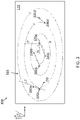
- FIG. 3 shows an exemplary nozzle configuration 300 to create an exemplary vortex 310 of a low stability fire suppression agent according to one or more embodiments.
- An x axis and y axis are indicated for the purpose of discussing discharge angles, which are referenced to the y axis (e.g., exemplary indicated angle a is 30 degrees).
- Four nozzles 320a, 320b, 320c, 320d (generally referred to as 320) are shown to be arranged along a line (i.e., along the x axis at a same y value) across the center of the divider 115.
- the directional discharge 330a, 330b, 330c, 330d (generally referred to as 330) of each of the nozzles 320 is indicated.
- the directional discharge of each nozzle 320 is selected to generate and maintain the vortex 310 of fire suppression agent.
- Exemplary angles of directional discharge 330 are 30 degrees for nozzle 320a, 60 degrees for nozzle 320b, 240 degrees for nozzle 320c, and 210 degrees for nozzle 320d. These exemplary angles ensure that directional discharge 330 from each of the nozzles 320 aligns with the vortex 310.
- this discharge would not contribute to the flow of the vortex 310 but, instead, would interfere with the flow of the vortex 310 and, thus, the uniform mixing and distribution facilitated by the vortex 310.
- the discharge from a given nozzle 320 should be between a normal line N to the center of the vortex 310 and a perpendicular line P that is perpendicular to that normal line N. This is shown for the nozzle 320c in FIG. 3 .
- the normal line N is from the nozzle 320c to the center of the vortex 310, and the perpendicular line P is 90 degrees from the normal line N.
- the directional discharge 330c is between the normal line N and the perpendicular line P.
- the perpendicular line P originating at the nozzle 320c must be in the direction of flow of the vortex 310 (i.e., perpendicular line P rather than line P').
- an optimal angle of the directional discharge 330 from a given nozzle 320 results in a spray that is aligned with the streamlines of the desired vortex 310.
- the range of acceptable angles can then be determined by comparing the angle of the spray with the angle of the streamlines of the vortex 310. That is, a line tangent to a point in the rotational flow of the vortex 310 (e.g., a point along the normal line N) and the directional discharge 330 (e.g., the center of a directional discharge 330 that covers a range of angles) must be aligned such that their dot product is positive.
- An exemplary tangent line T relevant to nozzle 320b is indicated in FIG. 3 .
- each nozzle 320 may include more than one orifice and/or emit fire suppression agent over a range of spray angles (e.g., over 90 degrees in total).
- the exemplary angles noted above may be varied while still aligning the directional discharge 330 with the direction of rotation of the rotational flow of the vortex 310 or at least not interfering with the flow of the vortex 310.
- the amount of variation (in a single discharge angle or a range of angles of discharge from a given nozzle 320) that facilitates still aligning the directional discharge 330 with the flow of the vortex 310 may depend on the position of the nozzle 320. As noted above, in general, the discharge from a given nozzle 320 is limited to the 90 degrees between the normal line N to the center of the corresponding vortex 310 and the perpendicular line P to the normal line N.
- the above-noted angles of directional discharge 330 for nozzles 320b and 320c may be varied by ⁇ 10 degrees or the nozzles 320b and 320c may have a range of angles of directional discharge, centered at the above-noted angles and spanning a range of ⁇ 10 degrees while still aligning with the rotational flow of the vortex 310.
- the indicated angles of directional discharge 330 for the nozzles 320a and 320d may be varied by ⁇ 30 degrees or the nozzles 320a and 320d may have a range of angles of directional discharge, centered at the above-noted angles and spanning a range of ⁇ 30 degrees while still aligning with the flow of the vortex 310.
- the larger span or variation in the angles of directional discharge 330 by the nozzles 320a, 320d is based on the position of those nozzles 320a, 320d relative to the vortex 310.
- one of the nozzles 320b or 320c may be eliminated while maintaining the vortex 310, although the energy of the vortex 310 may be decreased with fewer nozzles 320 providing directional discharge 330 that aligns with the rotational flow of the vortex 310.
- adding more nozzles 320 to the configuration 300 that are oriented to discharge fire suppression agent in a direction that aligns with the flow of the vortex 310 may add energy to the vortex 310.
- the numbers of nozzles 320 are not intended to be limited by the exemplary nozzle configuration 300.
- the vortex 310 is a region in a fluid (i.e., dispersed fire suppression agent) in which the flow revolves around an axis line (straight or curved) and forms a closed loop. Stated differently, the vortex 310 is a directional field of flow. As shown in FIG. 3 , the vortex 310 spirals around the cargo bay 110. The vortex 310 is the largest field of flow in the space (i.e., cargo compartment 110) or subspace, as in the case of FIGS. 5 and 6 . As discussed with reference to FIGS. 4-6 , each of the exemplary nozzle configurations 400, 500, 600 is designed to generate and maintain the structure of the largest spiral vortex 310 within the space or subspace of the cargo bay 110.
- FIG. 4 shows an exemplary nozzle configuration 400 to create an exemplary vortex 310 of a low stability fire suppression agent according to one or more embodiments. While the positions of the nozzles 320a, 320b, 320c, 320d (generally referred to as 320) shown in FIG. 4 differ from the nozzle configuration 300 shown in FIG. 3 , both nozzle configurations 300, 400 generate a similar vortex 310. That is, while the nozzles 320 in FIG. 3 are in a line, the nozzles 320 in FIG. 4 are arranged on the four sides of the separator 115. Specifically, the nozzles 320b and 320c are placed differently in FIG. 4 than in FIG. 3 while the nozzles 320a and 320d are in the same position in FIG. 4 as in FIG. 3 .
- angles of the directional discharges 330b, 330c (generally referred to as 330) from the nozzles 320b, 320c, respectively, are different than those shown in FIG. 3 while the angles of the directional discharges 330a, 330d (generally referred to as 330) from the nozzles 320a, 320d, respectively, are the same as those shown in FIG. 3 .
- Exemplary angles of directional discharge 330 are 30 degrees for nozzle 320a, 10 degrees for nozzle 320b, 260 degrees for nozzle 320c, and 210 degrees for nozzle 320d.
- these angles may span a range or be varied while still aligning the directional discharge 330 with the flow of the vortex 310.
- a directional discharge 330 over a range of angles is shown and the angle at the center of the range is indicated above.
- the range of angles for the directional discharge 330 by the nozzles 320a, 320d is greater than the range of angles for the directional discharge 330 by the nozzles 320b, 320c due to their position relative to the vortex 310.
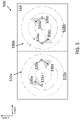
- FIG. 5 shows an exemplary nozzle configuration 500 to create an exemplary vortices 310a, 310b (generally referred to as 310) of a fire suppression agent according to one or more embodiments.
- the space which is the cargo compartment 110 in the exemplary case, is divided into two regions 510a, 510b (indicated by the dashed line) in the example shown in FIG. 5 .
- the single region is the cargo compartment 110 itself.
- Nozzles 320a and 320b are in the first region 510a and generate vortex 310a with their respective directional discharges 330a, 330b of fire suppression agent.
- Nozzles 320c and 320d are in the second region 510b and generate vortex 310b with their respective directional discharges 330c, 330d of fire suppression agent.
- the direction of flow (i.e., direction of rotation of rotational flows) of the vortices 310a, 310b must be generated such that the two adj acent vortices 310a, 310b rotate in opposite directions in order to prevent them from merging. As indicated in FIG.
- the nozzles 320a, 320b are arranged and configured to provide directional discharges 330a, 330b that align with the desired vortex 310a while the nozzles 320c, 320d are arranged and configured to provide directional discharges 330c, 330d that align with the desired vortex 310b.
- FIG. 6 shows an exemplary nozzle configuration 600 to create exemplary vortices 310a, 310b, 310c (generally referred to as 310) of a fire suppression agent according to one or more embodiments.
- the space which is the cargo compartment 110 in the exemplary case, is divided into three regions 610a, 610b, 610c (indicated by the dashed lines) in the example shown in FIG. 6 .
- Nozzles 320a and 320b are in the first region 610a and generate vortex 310a with their respective directional discharges 330a, 330b of fire suppression agent.
- Nozzles 320c and 320d are in the second region 610b and generate vortex 310b with their respective directional discharges 330c, 330d of fire suppression agent.
- Nozzles 320e and 320f are in the third region 610c and generate vortex 310c with their respective directional discharges 330e, 330f of fire suppression agent.
- the normal line N and the perpendicular line P to the normal line N in the direction of flow of the vortex 310c are indicated for nozzle 320e.
- the directional discharge 330e from nozzle 320e should be between the 90 degrees defined by the normal line N and the perpendicular line P in order to generate and maintain the vortex 310c.
- adjacent vortices 310 must flow in opposite directions to keep from merging.
- the two outer vortices 310a, 310c flow clockwise while the center vortex 310b, which is adjacent to both vortices 310a, 310c, flows counter-clockwise.
- the center vortex 310b which is adjacent to both vortices 310a, 310c, flows counter-clockwise.
- the nozzles 320a, 320b are arranged and configured to provide directional discharges 330a, 330b that align with the desired vortex 310a
- the nozzles 320c, 320d are arranged and configured to provide directional discharges 330c, 330d that align with the desired vortex 310b
- the nozzles 320e, 320f are arranged and configured to provide directional discharges 330e, 330f that align with the desired vortex 310c.
- FIG. 7 is a process flow of a method 700 of arranging nozzles 320 to create one or more vortices 310 as part of a fire suppression system according to one or more embodiments.
- the exemplary space for placement of the fire suppression system is the cargo bay 110 of an aircraft 100.
- determining the number of regions refers to determining if the cargo bay 110 should be treated as a single region as shown in FIG. 3 and 4 or subdivided into regions 510, 610 as shown in FIGS. 5 and 6 . This determination may be based on the size or aspect ratio of the cargo bay 110.
- the selection of the number of nozzles 320 per region, at block 720, and, more particularly, a limit on the total number of nozzles 320 may additional be used to determine the number of regions.
- a limit on the total number of nozzles 320 may additional be used to determine the number of regions.
- Computational fluid dynamic modeling may be used to select the number of regions (at block 710) and the number of nozzles per region (at block 720) to maximize distribution and mixing of fire suppression agent.
- arranging the nozzles 320 in each region and configuring the discharge 330 to generate a vortex 310 within each region refers to the range and variation in angles of the directional discharge 330 from each nozzle 320 as well as the direction in which adjacent vortices 310 are generated.
- the directional discharge of each nozzle 320 is configured to be aligned with the vortex 310 that is helps to generate and maintain. This alignment means that the directional discharge is between a normal line N from a given nozzle 320 to the center of the vortex 310 being generated and maintained by the nozzle 320 and a perpendicular line P to the normal line N.
- the alignment may also be considered based on a tangent line T to a point in the rotational flow of the vortex 310. Adjacent vortices 310 are generated to flow in opposite directions to maintain the separate vortices 310.
Landscapes
- Health & Medical Sciences (AREA)
- Public Health (AREA)
- Business, Economics & Management (AREA)
- Emergency Management (AREA)
- Nozzles (AREA)
Abstract
Description
- Exemplary embodiments pertain to the art of aircraft fire suppression and, in particular, to nozzle configurations to create a vortex of a fire suppression agent.
- Smoke detection and fire suppression are important functions in many environments. In an aircraft, for example, the functions are critical. This is because, unlike in other environments where escape is possible, quick suppression of a fire is vital to the integrity of the aircraft and the safety of the passengers. Smoke detection systems monitor the cargo compartment. Once an overheat or fire condition is detected, a fire suppression agent is discharged. This suppression may be undertaken in two stages, an initial phase followed by a sustained phase.
- In one embodiment, a fire suppression system in an aircraft includes a first nozzle within a region, the first nozzle performs discharge of a fire suppression agent in a first direction within a region. The system also includes a second nozzle within the region, the second nozzle performs discharge of the fire suppression agent in a second direction within the region. The discharge in the first direction by the first nozzle and the discharge in the second direction by the second nozzle generate and maintain a vortex of the fire suppression agent that occupies the region with rotational flow.
- Additionally or alternatively, in this or other embodiments, the system also includes an additional nozzle within the region to perform discharge of the fire suppression agent in an additional direction.
- Additionally or alternatively, in this or other embodiments, the discharge in the additional direction by the additional nozzle aligns with the flow direction of the vortex.
- Additionally or alternatively, in this or other embodiments, the region is a cargo bay of the aircraft.
- Additionally or alternatively, in this or other embodiments, the region is a portion of a cargo bay of the aircraft.
- Additionally or alternatively, in this or other embodiments, the system also includes a third nozzle and a fourth nozzle within a second region that is a different portion of the cargo bay of the aircraft.
- Additionally or alternatively, in this or other embodiments, the third nozzle performs discharge of the fire suppression agent in a third direction within the second region and the fourth nozzle performs discharge of the fire suppression agent in a fourth direction within the second region.
- Additionally or alternatively, in this or other embodiments, the discharge in the third direction by the third nozzle and the discharge in the fourth direction by the fourth nozzle generate and maintain a second vortex of the fire suppression agent within the second region with a rotational flow direction that is opposite that of the first vortex.
- Additionally or alternatively, in this or other embodiments, the system also includes two or more additional nozzles within one or more additional regions that are different portions of the cargo bay of the aircraft.
- Additionally or alternatively, in this or other embodiments, the two or more additional nozzles are configured to perform discharge of the fire suppression agent in the one or more additional regions to generate one or more additional vortices that are additional to the vortex, each pair of adjacent vortices being generated to rotate in opposite directions.
- In another embodiment, a method of assembling a fire suppression system in an aircraft includes disposing a first nozzle within a region and configuring the first nozzle to perform discharge of a fire suppression agent in a first direction within a region. The method also includes disposing a second nozzle within the region and configuring the second nozzle to perform discharge of the fire suppression agent in a second direction within the region. The discharge in the first direction by the first nozzle and the discharge in the second direction by the second nozzle generate and maintain a vortex of the fire suppression agent that occupies the region with rotational flow.
- Additionally or alternatively, in this or other embodiments, the method also includes disposing an additional nozzle within the region and configuring the additional nozzle to perform discharge of the fire suppression agent in an additional direction.
- Additionally or alternatively, in this or other embodiments, performing the discharge in the additional direction by the additional nozzle maintains the vortex based on the additional direction aligning with the flow direction of the vortex.
- Additionally or alternatively, in this or other embodiments, the region is a cargo bay of the aircraft.
- Additionally or alternatively, in this or other embodiments, the region is a portion of a cargo bay of the aircraft.
- Additionally or alternatively, in this or other embodiments, the method also includes disposing a third nozzle and a fourth nozzle within a second region that is a different portion of the cargo bay of the aircraft.
- Additionally or alternatively, in this or other embodiments, the method also includes configuring the third nozzle to perform discharge of the fire suppression agent in a third direction within the second region and configuring the fourth nozzle to perform discharge of the fire suppression agent in a fourth direction within the second region.
- Additionally or alternatively, in this or other embodiments, performing the discharge in the third direction by the third nozzle and performing the discharge in the fourth direction by the fourth nozzle generates and maintains a second vortex of the fire suppression agent within the second region with a rotational flow direction that is opposite that of the first vortex.
- Additionally or alternatively, in this or other embodiments, the method also includes disposing two or more additional nozzles within one or more additional regions that are different portions of the cargo bay of the aircraft.
- Additionally or alternatively, in this or other embodiments, the method also includes configuring the two or more additional nozzles to perform discharge of the fire suppression agent in the one or more additional regions to generate one or more additional vortices that are additional to the vortex, each pair of adjacent vortices being generated to rotate in opposite directions.
- The following descriptions should not be considered limiting in any way. With reference to the accompanying drawings, like elements are numbered alike:
-
FIG. 1 illustrates aspects of an aircraft that includes exemplary nozzle configurations to create one or more vortices of a fire suppression agent according to one or more embodiments; -
FIG. 2 is a cross-sectional view through A-A of the cargo compartment that includes exemplary nozzle configurations to create one or more vortices of a low stability fire suppression agent according to one or more embodiments; -
FIG. 3 shows an exemplary nozzle configuration to create an exemplary vortex of a low stability fire suppression agent according to one or more embodiments; -
FIG. 4 shows another exemplary nozzle configuration to create an exemplary vortex of a low stability fire suppression agent according to one or more embodiments; -
FIG. 5 shows an exemplary nozzle configuration to create two exemplary vortices of a low stability fire suppression agent according to one or more embodiments; -
FIG. 6 shows an exemplary nozzle configuration to create three exemplary vortices of a low stability fire suppression agent according to one or more embodiments; and -
FIG. 7 is a process flow of a method of assembling a nozzle configuration to create one or more vortices of low stability fire suppression agent according to one or more embodiments. - A detailed description of one or more embodiments of the disclosed apparatus and method are presented herein by way of exemplification and not limitation with reference to the Figures.
- As previously noted, fire suppression is an important function in aircraft systems. In prior aircraft fire suppression systems, Halon 1301 is distributed into the cargo bay, for example, via a distribution system. Halon is an ozone-depleting substance whose production has ceased under the Montreal Protocol. Thus, environmentally friendly fire suppression agents are being developed as replacements for Halon.
- Embodiments of the systems and methods detailed herein relate to nozzle configurations to create one or more vortices of a fire suppression agent. Recently, trifluoroiodomethane or trifluoromethyl iodide (CF3I) has been considered as an efficient and environmentally friendly fire suppression agent. However, CF3I, which is a low stability fire suppression agent as compared with Halon, for example, starts to break down at high temperatures (e.g., temperatures over 600 °F). According to exemplary embodiments, the flow rate of the fire suppression agent is increased. This generates turbulence within the discharge of the fire suppression agent. Additionally, nozzles that disperse the fire suppression agent are configured for directional emission rather than omnidirectional emission as before. Further, the nozzles are arranged such that two or more nozzles create a vortex (e.g., spiral vortex) of the fire suppression agent. Thus, the turbulence generated by the increased rate of discharge is channeled into a fluid flow with a vortex structure. This increases distribution and uniformity of the fire suppression agent and prolongs the time before the fire suppression agent breaks down.
- As noted, the vortex created by the arrangement of the directional nozzles increases distribution and mixing of the fire suppression agent in the environment. The mixing, in turn, decreases the highest temperatures in the environment and causes more of the temperature within the environment to be closer to the average temperature. The temperature effect means that the low stability fire suppression agent will take longer to break down and, thus, will be more effective in suppressing the fire in the environment. An exemplary environment discussed for explanatory purposes is the cargo area of the aircraft.
-
FIG. 1 illustrates aspects of anaircraft 100 that includesexemplary nozzle configurations FIGS. 3-6 ) to create one or more vortices 310 (FIGS. 3-6 ) of a fire suppression agent according to one or more embodiments. Theexemplary aircraft 100 includes acargo compartment 110 and apassenger compartment 120, separated by adivider 115 that is generally indicated by the dashed line inFIG. 1 . While theexemplary passenger compartment 120 is shown as one level, thepassenger compartment 120 may include multiple levels according to alternate embodiments.Exemplary nozzle configurations FIGS. 3-6 . Fire suppression components are also generally present in other parts of the aircraft 100 (e.g.,passenger compartment 120, engines, cockpit) but are not indicated. A cross-section indicated as A-A is shown inFIG. 2 . -
FIG. 2 is a cross-sectional view through A-A of thecargo compartment 110 that includesexemplary nozzle configurations FIGS. 3-6 ) to create one or more vortices 310 (FIGS. 3-6 ) of a low stability fire suppression agent according to one or more embodiments. Thepassenger compartment 120 is indicated above thecargo compartment 110. The twocompartments divider 115 that defines a ceiling of thecargo compartment 110 and a floor of thepassenger compartment 120. An exemplaryfire detection system 205 is shown at the ceiling level of thecargo compartment 110. As shown inFIGS. 3-6 , nozzles 320 that discharge fire suppression agent may also be located at the ceiling level of thecargo compartment 110. According to alternate embodiments, the nozzles 320 may be located lower within thecargo compartment 110 instead. -
FIGS. 3-6 illustratedifferent nozzle configurations more vortices 310 according to exemplary embodiments. In each ofFIGS. 3-6 , the view is looking up at the divider 115 (i.e., the ceiling of the cargo compartment 110) from within thecargo compartment 110. As previously noted, although the nozzles 320 shown inFIGS. 3-6 are shown at the ceiling level for explanatory purposes, the nozzles 320 may instead be arranged lower in thecargo compartment 110 according to alternate embodiments. In addition, the flow rate used for discharge of fire suppression agent from each of the nozzles 320 may be increased as compared with typical discharge rates in aircraft applications in order to generate thevortices 310. For example, while the fire suppression agent may be fully dispersed in about a minute according to previous systems, the flow rate may be increased, according to one or more embodiments, to complete the discharge in about 10 seconds or in less than 30 seconds. -
FIG. 3 shows anexemplary nozzle configuration 300 to create anexemplary vortex 310 of a low stability fire suppression agent according to one or more embodiments. An x axis and y axis are indicated for the purpose of discussing discharge angles, which are referenced to the y axis (e.g., exemplary indicated angle a is 30 degrees). Fournozzles divider 115. - The
directional discharge vortex 310 of fire suppression agent. Exemplary angles of directional discharge 330 are 30 degrees fornozzle 320a, 60 degrees fornozzle 320b, 240 degrees fornozzle 320c, and 210 degrees fornozzle 320d. These exemplary angles ensure that directional discharge 330 from each of the nozzles 320 aligns with thevortex 310. Ifnozzle 320a emitted a directional discharge DD at 120 degrees, as indicated, this discharge (DD) would not contribute to the flow of thevortex 310 but, instead, would interfere with the flow of thevortex 310 and, thus, the uniform mixing and distribution facilitated by thevortex 310. - In general, according to one or more embodiments, the discharge from a given nozzle 320 should be between a normal line N to the center of the
vortex 310 and a perpendicular line P that is perpendicular to that normal line N. This is shown for thenozzle 320c inFIG. 3 . The normal line N is from thenozzle 320c to the center of thevortex 310, and the perpendicular line P is 90 degrees from the normal line N. As shown, thedirectional discharge 330c is between the normal line N and the perpendicular line P. The perpendicular line P originating at thenozzle 320c must be in the direction of flow of the vortex 310 (i.e., perpendicular line P rather than line P'). In other words, an optimal angle of the directional discharge 330 from a given nozzle 320 results in a spray that is aligned with the streamlines of the desiredvortex 310. The range of acceptable angles can then be determined by comparing the angle of the spray with the angle of the streamlines of thevortex 310. That is, a line tangent to a point in the rotational flow of the vortex 310 (e.g., a point along the normal line N) and the directional discharge 330 (e.g., the center of a directional discharge 330 that covers a range of angles) must be aligned such that their dot product is positive. An exemplary tangent line T relevant tonozzle 320b is indicated inFIG. 3 . - For explanatory purposes, a single directional discharge 330 is shown from each nozzle 320 at the above-noted angle. In alternate embodiments, each nozzle 320 may include more than one orifice and/or emit fire suppression agent over a range of spray angles (e.g., over 90 degrees in total). In addition, the exemplary angles noted above (or a range of angles of discharge) may be varied while still aligning the directional discharge 330 with the direction of rotation of the rotational flow of the
vortex 310 or at least not interfering with the flow of thevortex 310. The amount of variation (in a single discharge angle or a range of angles of discharge from a given nozzle 320) that facilitates still aligning the directional discharge 330 with the flow of thevortex 310 may depend on the position of the nozzle 320. As noted above, in general, the discharge from a given nozzle 320 is limited to the 90 degrees between the normal line N to the center of thecorresponding vortex 310 and the perpendicular line P to the normal line N. - For example, the above-noted angles of directional discharge 330 for
nozzles nozzles vortex 310. The indicated angles of directional discharge 330 for thenozzles nozzles vortex 310. The larger span or variation in the angles of directional discharge 330 by thenozzles nozzles vortex 310. - In addition, one of the
nozzles vortex 310, although the energy of thevortex 310 may be decreased with fewer nozzles 320 providing directional discharge 330 that aligns with the rotational flow of thevortex 310. On the other hand, adding more nozzles 320 to theconfiguration 300 that are oriented to discharge fire suppression agent in a direction that aligns with the flow of thevortex 310 may add energy to thevortex 310. The numbers of nozzles 320 are not intended to be limited by theexemplary nozzle configuration 300. - In fluid dynamics, the
vortex 310 is a region in a fluid (i.e., dispersed fire suppression agent) in which the flow revolves around an axis line (straight or curved) and forms a closed loop. Stated differently, thevortex 310 is a directional field of flow. As shown inFIG. 3 , thevortex 310 spirals around thecargo bay 110. Thevortex 310 is the largest field of flow in the space (i.e., cargo compartment 110) or subspace, as in the case ofFIGS. 5 and6 . As discussed with reference toFIGS. 4-6 , each of theexemplary nozzle configurations largest spiral vortex 310 within the space or subspace of thecargo bay 110. -
FIG. 4 shows anexemplary nozzle configuration 400 to create anexemplary vortex 310 of a low stability fire suppression agent according to one or more embodiments. While the positions of thenozzles FIG. 4 differ from thenozzle configuration 300 shown inFIG. 3 , bothnozzle configurations similar vortex 310. That is, while the nozzles 320 inFIG. 3 are in a line, the nozzles 320 inFIG. 4 are arranged on the four sides of theseparator 115. Specifically, thenozzles FIG. 4 than inFIG. 3 while thenozzles FIG. 4 as inFIG. 3 . - As a result, the angles of the
directional discharges nozzles FIG. 3 while the angles of thedirectional discharges nozzles FIG. 3 . Exemplary angles of directional discharge 330 are 30 degrees fornozzle 320a, 10 degrees fornozzle 320b, 260 degrees fornozzle 320c, and 210 degrees fornozzle 320d. As noted for theexemplary nozzle configuration 300 shown inFIG. 3 , these angles may span a range or be varied while still aligning the directional discharge 330 with the flow of thevortex 310. In the embodiment shown inFIG. 4 , a directional discharge 330 over a range of angles is shown and the angle at the center of the range is indicated above. As show inFIG. 4 , the range of angles for the directional discharge 330 by thenozzles nozzles vortex 310. -
FIG. 5 shows anexemplary nozzle configuration 500 to create anexemplary vortices cargo compartment 110 in the exemplary case, is divided into tworegions FIG. 5 . InFIGS. 3 and4 , the single region is thecargo compartment 110 itself.Nozzles first region 510a and generatevortex 310a with their respectivedirectional discharges Nozzles second region 510b and generatevortex 310b with their respectivedirectional discharges vortices adj acent vortices FIG. 5 , thenozzles directional discharges vortex 310a while thenozzles directional discharges vortex 310b. -
FIG. 6 shows anexemplary nozzle configuration 600 to createexemplary vortices cargo compartment 110 in the exemplary case, is divided into threeregions FIG. 6 .Nozzles first region 610a and generatevortex 310a with their respectivedirectional discharges Nozzles second region 610b and generatevortex 310b with their respectivedirectional discharges Nozzles third region 610c and generatevortex 310c with their respectivedirectional discharges vortex 310c are indicated fornozzle 320e. As discussed with reference toFIG. 3 , thedirectional discharge 330e fromnozzle 320e should be between the 90 degrees defined by the normal line N and the perpendicular line P in order to generate and maintain thevortex 310c. - As noted with reference to
FIG. 5 ,adjacent vortices 310 must flow in opposite directions to keep from merging. Thus, the twoouter vortices center vortex 310b, which is adjacent to bothvortices FIG. 6 , thenozzles directional discharges vortex 310a, thenozzles directional discharges vortex 310b, and thenozzles directional discharges vortex 310c. -
FIG. 7 is a process flow of amethod 700 of arranging nozzles 320 to create one ormore vortices 310 as part of a fire suppression system according to one or more embodiments. The exemplary space for placement of the fire suppression system is thecargo bay 110 of anaircraft 100. Atblock 710, determining the number of regions refers to determining if thecargo bay 110 should be treated as a single region as shown inFIG. 3 and4 or subdivided into regions 510, 610 as shown inFIGS. 5 and6 . This determination may be based on the size or aspect ratio of thecargo bay 110. According to exemplary embodiments, the selection of the number of nozzles 320 per region, atblock 720, and, more particularly, a limit on the total number of nozzles 320 may additional be used to determine the number of regions. For example, for the same size ofcargo bay 110, being limited to three or four nozzles 320 precludes subdivision into three regions as shown inFIG. 6 , for example. Computational fluid dynamic modeling may be used to select the number of regions (at block 710) and the number of nozzles per region (at block 720) to maximize distribution and mixing of fire suppression agent. - At
block 730, arranging the nozzles 320 in each region and configuring the discharge 330 to generate avortex 310 within each region refers to the range and variation in angles of the directional discharge 330 from each nozzle 320 as well as the direction in whichadjacent vortices 310 are generated. As previously noted, the directional discharge of each nozzle 320 is configured to be aligned with thevortex 310 that is helps to generate and maintain. This alignment means that the directional discharge is between a normal line N from a given nozzle 320 to the center of thevortex 310 being generated and maintained by the nozzle 320 and a perpendicular line P to the normal line N. The alignment may also be considered based on a tangent line T to a point in the rotational flow of thevortex 310.Adjacent vortices 310 are generated to flow in opposite directions to maintain theseparate vortices 310. - The terminology used herein is for the purpose of describing particular embodiments only and is not intended to be limiting of the present disclosure. As used herein, the singular forms "a", "an" and "the" are intended to include the plural forms as well, unless the context clearly indicates otherwise. It will be further understood that the terms "comprises" and/or "comprising," when used in this specification, specify the presence of stated features, integers, steps, operations, elements, and/or components, but do not preclude the presence or addition of one or more other features, integers, steps, operations, element components, and/or groups thereof.
- While the present disclosure has been described with reference to an exemplary embodiment or embodiments, it will be understood by those skilled in the art that various changes may be made and equivalents may be substituted for elements thereof without departing from the scope of the present disclosure. In addition, many modifications may be made to adapt a particular situation or material to the teachings of the present disclosure without departing from the essential scope thereof. Therefore, it is intended that the present disclosure not be limited to the particular embodiment disclosed as the best mode contemplated for carrying out this present disclosure, but that the present disclosure will include all embodiments falling within the scope of the claims.
Claims (15)
- A fire suppression system in an aircraft comprising:a first nozzle within a region, the first nozzle being configured to perform discharge of a fire suppression agent in a first direction within a region; anda second nozzle within the region, the second nozzle being configured to perform discharge of the fire suppression agent in a second direction within the region, wherein the discharge in the first direction by the first nozzle and the discharge in the second direction by the second nozzle generate and maintain a vortex of the fire suppression agent that occupies the region with rotational flow.
- The system according to claim 1, further comprising an additional nozzle within the region configured to perform discharge of the fire suppression agent in an additional direction.
- The system according to claim 2, wherein the discharge in the additional direction by the additional nozzle aligns with the flow direction of the vortex.
- The system according to any preceding claim, wherein the region is a cargo bay of the aircraft.
- The system according to any one of claims 1-3, wherein the region is a portion of a cargo bay of the aircraft.
- The system according to claim 5, further comprising a third nozzle and a fourth nozzle within a second region that is a different portion of the cargo bay of the aircraft.
- The system according to claim 6, wherein the third nozzle is configured to perform discharge of the fire suppression agent in a third direction within the second region and the fourth nozzle is configured to perform discharge of the fire suppression agent in a fourth direction within the second region.
- The system according to claim 7, wherein the discharge in the third direction by the third nozzle and the discharge in the fourth direction by the fourth nozzle generate and maintain a second vortex of the fire suppression agent within the second region with a rotational flow direction that is opposite that of the first vortex.
- The system according to any one of claims 5-8, further comprising two or more additional nozzles within one or more additional regions that are different portions of the cargo bay of the aircraft;
optionally wherein the two or more additional nozzles are configured to perform discharge of the fire suppression agent in the one or more additional regions to generate one or more additional vortices that are additional to the vortex, each pair of adjacent vortices being generated to rotate in opposite directions. - A method of assembling a fire suppression system in an aircraft, the method comprising:disposing a first nozzle within a region and configuring the first nozzle to perform discharge of a fire suppression agent in a first direction within a region; anddisposing a second nozzle within the region and configuring the second nozzle to perform discharge of the fire suppression agent in a second direction within the region, wherein the discharge in the first direction by the first nozzle and the discharge in the second direction by the second nozzle generate and maintain a vortex of the fire suppression agent that occupies the region with rotational flow.
- The method according to claim 10, further comprising disposing an additional nozzle within the region and configuring the additional nozzle to perform discharge of the fire suppression agent in an additional direction;
optionally wherein performing the discharge in the additional direction by the additional nozzle maintains the vortex based on the additional direction aligning with the flow direction of the vortex. - The method according to claim 10 or 11, wherein the region is a cargo bay of the aircraft.
- The method according to claim 10 or 11, wherein the region is a portion of a cargo bay of the aircraft.
- The method according to claim 13, further comprising disposing a third nozzle and a fourth nozzle within a second region that is a different portion of the cargo bay of the aircraft;optionally comprising configuring the third nozzle to perform discharge of the fire suppression agent in a third direction within the second region and configuring the fourth nozzle to perform discharge of the fire suppression agent in a fourth direction within the second region;and further optionally wherein performing the discharge in the third direction by the third nozzle and performing the discharge in the fourth direction by the fourth nozzle generates and maintains a second vortex of the fire suppression agent within the second region with a rotational flow direction that is opposite that of the first vortex.
- The method according to claim 13 or 14, further comprising disposing two or more additional nozzles within one or more additional regions that are different portions of the cargo bay of the aircraft;
optionally comprising configuring the two or more additional nozzles to perform discharge of the fire suppression agent in the one or more additional regions to generate one or more additional vortices that are additional to the vortex, each pair of adjacent vortices being generated to rotate in opposite directions.
Applications Claiming Priority (1)
| Application Number | Priority Date | Filing Date | Title |
|---|---|---|---|
| US17/104,105 US11717839B2 (en) | 2020-11-25 | 2020-11-25 | Nozzle configurations to create a vortex of fire suppression agent |
Publications (1)
| Publication Number | Publication Date |
|---|---|
| EP4005643A1 true EP4005643A1 (en) | 2022-06-01 |
Family
ID=78770385
Family Applications (1)
| Application Number | Title | Priority Date | Filing Date |
|---|---|---|---|
| EP21209742.2A Pending EP4005643A1 (en) | 2020-11-25 | 2021-11-23 | Nozzle configurations to create a vortex of fire suppression agent |
Country Status (2)
| Country | Link |
|---|---|
| US (1) | US11717839B2 (en) |
| EP (1) | EP4005643A1 (en) |
Families Citing this family (4)
| Publication number | Priority date | Publication date | Assignee | Title |
|---|---|---|---|---|
| US11717839B2 (en) * | 2020-11-25 | 2023-08-08 | Kidde Technologies, Inc. | Nozzle configurations to create a vortex of fire suppression agent |
| US11846548B2 (en) * | 2021-03-16 | 2023-12-19 | Kidde Technologies, Inc. | Protective sleeves for fire and overheat detection systems for aircraft applications |
| CN115212500B (en) * | 2022-06-16 | 2024-04-30 | 香港理工大学深圳研究院 | Fire extinguishing method and system for generating continuous vortex ring |
| US20230414981A1 (en) * | 2022-06-24 | 2023-12-28 | The Boeing Company | Systems and methods for configuring fire extinguishers within a compartment |
Citations (7)
| Publication number | Priority date | Publication date | Assignee | Title |
|---|---|---|---|---|
| US2452348A (en) * | 1945-06-23 | 1948-10-26 | Cardox Corp | Fire extinguishing method |
| DE896600C (en) * | 1942-11-10 | 1953-11-12 | Messerschmitt Boelkow Blohm | Automatic fire extinguishing system for vehicles, especially aircraft |
| SU1400621A1 (en) * | 1986-12-04 | 1988-06-07 | Тольяттинское Высшее Военное Строительное Командное Училище | Method of surface extinguishing of a fire in reservoirs filled with petroluem products |
| EP0850091B1 (en) * | 1996-06-14 | 2001-10-10 | SUNDHOLM, Göran | Fire fighting method and installation for extinguishing an elongated object |
| EP1299160B1 (en) * | 2000-07-12 | 2005-02-02 | Exel Industries | Stationary automatic fire-extinguishing installation |
| US20100218959A1 (en) * | 2001-09-19 | 2010-09-02 | Nanomist Systems, Llc | Method and device for suppression of fire by local flooding with ultra-fine water mist |
| US9421406B2 (en) * | 2013-08-05 | 2016-08-23 | Kidde Technologies, Inc. | Freighter cargo fire protection |
Family Cites Families (17)
| Publication number | Priority date | Publication date | Assignee | Title |
|---|---|---|---|---|
| US3645338A (en) * | 1969-10-08 | 1972-02-29 | Factory Mutual Res Corp | Fixed fire-extinguishing system |
| US4643260A (en) * | 1985-09-26 | 1987-02-17 | The Boeing Company | Fire suppression system with controlled secondary extinguishant discharge |
| US5211246A (en) * | 1989-05-30 | 1993-05-18 | The Boeing Company | Scouring method and system for suppressing fire in an enclosed area |
| US20040256118A1 (en) * | 2002-11-28 | 2004-12-23 | Kidde-Fenwal Inc. | Fire extinguisher discharge method and apparatus |
| US7066274B2 (en) * | 2004-02-25 | 2006-06-27 | The Boeing Company | Fire-suppression system for an aircraft |
| US9956445B2 (en) * | 2010-12-30 | 2018-05-01 | William Armand Enk, SR. | Fire suppression system |
| US9550080B2 (en) * | 2011-06-17 | 2017-01-24 | United Parcel Service Of America, Inc. | Suppressing a fire condition in an aircraft |
| EP2623159B1 (en) | 2012-02-02 | 2018-06-13 | Airbus Operations GmbH | Fire suppression system and method for fire suppression in an airborne vehicle |
| HUE030770T2 (en) * | 2012-02-05 | 2017-05-29 | Minimax Gmbh & Co Kg | Fire extinguishing system |
| EP3445146B1 (en) * | 2016-04-18 | 2024-01-03 | Precision Planting LLC | Application units to actuate at least one applicator arm for placement with respect to agricultural plants |
| US10240243B2 (en) * | 2017-05-05 | 2019-03-26 | Hamilton Sundstrand Corporation | Flow distributor hole pattern |
| US20200094089A1 (en) * | 2018-09-24 | 2020-03-26 | Kidde Technologies, Inc. | Aircraft fire suppression systems |
| US10859346B2 (en) * | 2018-10-31 | 2020-12-08 | Fortem Technologies, Inc. | System and method of managing a projectile module on a flying device |
| CN112090603B (en) * | 2019-06-17 | 2022-11-08 | 苏州天健云康信息科技有限公司 | Microfluidic device and method for manufacturing the same |
| US20210370111A1 (en) * | 2020-06-02 | 2021-12-02 | The Boeing Company | Aircraft zonal fire suppression systems and methods |
| US11717839B2 (en) * | 2020-11-25 | 2023-08-08 | Kidde Technologies, Inc. | Nozzle configurations to create a vortex of fire suppression agent |
| US20220401766A1 (en) * | 2021-06-22 | 2022-12-22 | The Boeing Company | Systems and methods for suppressing fire in a lavatory of a vehicle |
-
2020
- 2020-11-25 US US17/104,105 patent/US11717839B2/en active Active
-
2021
- 2021-11-23 EP EP21209742.2A patent/EP4005643A1/en active Pending
Patent Citations (7)
| Publication number | Priority date | Publication date | Assignee | Title |
|---|---|---|---|---|
| DE896600C (en) * | 1942-11-10 | 1953-11-12 | Messerschmitt Boelkow Blohm | Automatic fire extinguishing system for vehicles, especially aircraft |
| US2452348A (en) * | 1945-06-23 | 1948-10-26 | Cardox Corp | Fire extinguishing method |
| SU1400621A1 (en) * | 1986-12-04 | 1988-06-07 | Тольяттинское Высшее Военное Строительное Командное Училище | Method of surface extinguishing of a fire in reservoirs filled with petroluem products |
| EP0850091B1 (en) * | 1996-06-14 | 2001-10-10 | SUNDHOLM, Göran | Fire fighting method and installation for extinguishing an elongated object |
| EP1299160B1 (en) * | 2000-07-12 | 2005-02-02 | Exel Industries | Stationary automatic fire-extinguishing installation |
| US20100218959A1 (en) * | 2001-09-19 | 2010-09-02 | Nanomist Systems, Llc | Method and device for suppression of fire by local flooding with ultra-fine water mist |
| US9421406B2 (en) * | 2013-08-05 | 2016-08-23 | Kidde Technologies, Inc. | Freighter cargo fire protection |
Also Published As
| Publication number | Publication date |
|---|---|
| US20220161279A1 (en) | 2022-05-26 |
| US11717839B2 (en) | 2023-08-08 |
Similar Documents
| Publication | Publication Date | Title |
|---|---|---|
| US11717839B2 (en) | Nozzle configurations to create a vortex of fire suppression agent | |
| JP5568082B2 (en) | Improved mist generating apparatus and method | |
| AU2002251620B8 (en) | Liquid sprayers | |
| EP2207601B1 (en) | An improved mist generating apparatus | |
| RU2501610C1 (en) | Nozzle with uniform atomising cone | |
| US20050001065A1 (en) | Nozzle apparatus and method for atomizing fluids | |
| US20100006670A1 (en) | Device for ejecting a diphasic mixture | |
| EP1488830A1 (en) | Sprinkler | |
| KR20080012882A (en) | Fire extinguishing device and fire extinguishing head | |
| KR20070099608A (en) | Spray method and spray nozzle of medium | |
| WO2018204231A1 (en) | Mixer design for a plural component system | |
| US20210086203A1 (en) | High-Efficiency Smooth Bore Nozzles | |
| US10286240B2 (en) | Automatic nozzle for firefighting systems | |
| US20200141422A1 (en) | Media concentration device and method | |
| JP2017531553A (en) | Two-fluid nozzle | |
| WO2006104418A2 (en) | Liquid atomizer | |
| US20230081536A1 (en) | High-expansion foam generator | |
| US20040256118A1 (en) | Fire extinguisher discharge method and apparatus | |
| EP4058202A1 (en) | Sweeping jet device with multidirectional output | |
| EP4159289B1 (en) | Nozzle geometry to create rotational vortex | |
| KR101792313B1 (en) | Mixing nozzle and reactor comprising the same | |
| KR102474149B1 (en) | Fluid Supply Apparatus | |
| CN211800083U (en) | Gas-liquid mixing device | |
| JP2005046769A (en) | Spray nozzle and spray method using it | |
| EP3981475B1 (en) | High-pressure atomiser nozzle, lance including this nozzle and fire extinguishing system including this lance |
Legal Events
| Date | Code | Title | Description |
|---|---|---|---|
| PUAI | Public reference made under article 153(3) epc to a published international application that has entered the european phase |
Free format text: ORIGINAL CODE: 0009012 |
|
| STAA | Information on the status of an ep patent application or granted ep patent |
Free format text: STATUS: THE APPLICATION HAS BEEN PUBLISHED |
|
| AK | Designated contracting states |
Kind code of ref document: A1 Designated state(s): AL AT BE BG CH CY CZ DE DK EE ES FI FR GB GR HR HU IE IS IT LI LT LU LV MC MK MT NL NO PL PT RO RS SE SI SK SM TR |
|
| STAA | Information on the status of an ep patent application or granted ep patent |
Free format text: STATUS: REQUEST FOR EXAMINATION WAS MADE |
|
| 17P | Request for examination filed |
Effective date: 20221201 |
|
| RBV | Designated contracting states (corrected) |
Designated state(s): AL AT BE BG CH CY CZ DE DK EE ES FI FR GB GR HR HU IE IS IT LI LT LU LV MC MK MT NL NO PL PT RO RS SE SI SK SM TR |
|
| STAA | Information on the status of an ep patent application or granted ep patent |
Free format text: STATUS: EXAMINATION IS IN PROGRESS |
|
| 17Q | First examination report despatched |
Effective date: 20250702 |