EP4005545A1 - Port for an internal air distribution system of a patient support surface - Google Patents
Port for an internal air distribution system of a patient support surface Download PDFInfo
- Publication number
- EP4005545A1 EP4005545A1 EP21210441.8A EP21210441A EP4005545A1 EP 4005545 A1 EP4005545 A1 EP 4005545A1 EP 21210441 A EP21210441 A EP 21210441A EP 4005545 A1 EP4005545 A1 EP 4005545A1
- Authority
- EP
- European Patent Office
- Prior art keywords
- housing
- port
- support surface
- flange
- passageway
- Prior art date
- Legal status (The legal status is an assumption and is not a legal conclusion. Google has not performed a legal analysis and makes no representation as to the accuracy of the status listed.)
- Granted
Links
Images



Classifications
-
- A—HUMAN NECESSITIES
- A61—MEDICAL OR VETERINARY SCIENCE; HYGIENE
- A61G—TRANSPORT, PERSONAL CONVEYANCES OR ACCOMMODATION SPECIALLY ADAPTED FOR PATIENTS OR DISABLED PERSONS; OPERATING TABLES OR CHAIRS; CHAIRS FOR DENTISTRY; FUNERAL DEVICES
- A61G7/00—Beds specially adapted for nursing; Devices for lifting patients or disabled persons
- A61G7/05—Parts, details or accessories of beds
- A61G7/057—Arrangements for preventing bed-sores or for supporting patients with burns, e.g. mattresses specially adapted therefor
- A61G7/05784—Arrangements for preventing bed-sores or for supporting patients with burns, e.g. mattresses specially adapted therefor with ventilating means, e.g. mattress or cushion with ventilating holes or ventilators
-
- A—HUMAN NECESSITIES
- A61—MEDICAL OR VETERINARY SCIENCE; HYGIENE
- A61G—TRANSPORT, PERSONAL CONVEYANCES OR ACCOMMODATION SPECIALLY ADAPTED FOR PATIENTS OR DISABLED PERSONS; OPERATING TABLES OR CHAIRS; CHAIRS FOR DENTISTRY; FUNERAL DEVICES
- A61G7/00—Beds specially adapted for nursing; Devices for lifting patients or disabled persons
- A61G7/002—Beds specially adapted for nursing; Devices for lifting patients or disabled persons having adjustable mattress frame
- A61G7/018—Control or drive mechanisms
-
- A—HUMAN NECESSITIES
- A61—MEDICAL OR VETERINARY SCIENCE; HYGIENE
- A61G—TRANSPORT, PERSONAL CONVEYANCES OR ACCOMMODATION SPECIALLY ADAPTED FOR PATIENTS OR DISABLED PERSONS; OPERATING TABLES OR CHAIRS; CHAIRS FOR DENTISTRY; FUNERAL DEVICES
- A61G7/00—Beds specially adapted for nursing; Devices for lifting patients or disabled persons
- A61G7/05—Parts, details or accessories of beds
- A61G7/057—Arrangements for preventing bed-sores or for supporting patients with burns, e.g. mattresses specially adapted therefor
- A61G7/05769—Arrangements for preventing bed-sores or for supporting patients with burns, e.g. mattresses specially adapted therefor with inflatable chambers
-
- B—PERFORMING OPERATIONS; TRANSPORTING
- B01—PHYSICAL OR CHEMICAL PROCESSES OR APPARATUS IN GENERAL
- B01D—SEPARATION
- B01D45/00—Separating dispersed particles from gases or vapours by gravity, inertia, or centrifugal forces
- B01D45/04—Separating dispersed particles from gases or vapours by gravity, inertia, or centrifugal forces by utilising inertia
- B01D45/06—Separating dispersed particles from gases or vapours by gravity, inertia, or centrifugal forces by utilising inertia by reversal of direction of flow
Definitions
- the present disclosure relates to a port for an air distribution system. More specifically, the present disclosure relates to a port that can be mechanically integrated into an internal air distribution system, such as an air distribution system found in a patient mattress to redirect moisture from a surface a patient lies on.
- an internal air distribution system such as an air distribution system found in a patient mattress to redirect moisture from a surface a patient lies on.
- a support surface such as a mattress, used for patients for hospital beds, medical beds, or other types of beds may be used by a patient to spend an extended period of time on the support surface.
- Patients who are positioned on a mattress for an extended period of time are at risk of developing skin conditions, such as bed sores, due to heat and moisture along the interface of the patient with the surface of the mattress.
- Some mattresses used by patients have an air distribution system that may conduct air along the interface of a patient with the surface to keep the patient's skin cool and dry.
- such a mattress is integrated into the hospital bed so that the bed and mattress are interconnected electrically and the mattress is configured to fit on a particular version of a hospital bed.
- the integrations of mattresses to hospital beds has the benefit of allowing the bed and mattress to cooperate and share controls and power.
- the benefits of the mattress may not be experienced on beds where the integration of the mattress has not been made.
- the use of integrated systems may require additional expenses in a hospital bed that provides advanced functionality that is not necessary or cost effective in all cases.
- the challenge presented is the need for an external power system and air source for the mattress contained in a separate control box. This can be cumbersome as the control box must be positioned on or near the hospital bed and may create entanglement concerns, as well as generally taking up space.
- a mattress that has the necessary controls and air source within the mattress avoids these concerns.
- a challenge is presented in cases where the controls and air source are located within the mattress in that getting sufficient air flow, while also preventing unwanted materials from ingressing into the mattress can be a challenge.
- a patient support surface is configured to conduct air along a top face of the support surface so that heat and moisture from a patient lying on the support surface are conducted away from the top face of the support surface.
- the support surface comprises a lower cover, an air distribution layer, a port, and a blower assembly.
- the lower cover of the support surface is formed to include an opening formed in a side of the lower cover of the support surface.
- the air distribution layer is positioned within the support surface.
- the port defines a tortious path for a flow of air through the port.
- the port is positioned within the opening and hermetically sealed to the lower cover.
- the port includes a housing defining a lower surface having a descending angle configured to allow gravity to conduct liquids over the lower surface away from the tortious path.
- the blower assembly is operable to draw air through the port and push air through the air distribution layer.
- the port may include a cap secured within a passageway formed in the housing, the cap including a flange that is resiliently flexible such that the flange is deflectable to be positioned through the passageway and secure to the housing with an interference fit.
- the cap may include a second flange that is also resiliently flexible such that the second flange is deflectable to be positioned through the passageway and secure to the housing with an interference fit.
- one or more flanges of the cap may be welded to a portion of the housing to secure the cap to the housing.
- the port may further comprise a connector secured within the passageway formed in the housing, the connector including a flange that is resiliently flexible such that the flange is deflectable to be positioned through the passageway and secure to the housing with an interference fit.
- the connector may include a second flange that is also resiliently flexible such that the second flange is deflectable to be positioned through the passageway and secure to the housing with an interference fit.
- the support surface may further include a conduit extending between the connector and the blower assembly, the conduit positioned on the connector such that air that flows through the tortious path is conducted through the conduit and into the blower assembly.
- a port for a support surface comprises a housing, a cap, and a connector.
- the housing defines a cavity and a passageway having an outer surface.
- the housing further includes drain surface defining a descending angle positioned in the cavity and configured to allow gravity to conduct foreign materials over the outer surface of the passageway and over drain surface away from the passageway.
- the cap includes a resiliently pliable flange that is received within the passageway and expands within the housing such that the flange is secured to the housing by an interference fit. The cap and housing cooperating to define a tortious path for a flow of air through the port.
- the connector has first portion for securing the connector to a conduit and a second portion, the second portion including a resiliently pliable flange that is received within the passageway and expands within the housing such that the flange is secured to the housing by an interference fit.
- the housing may include a flange configured to engage a material about the periphery of the housing to be hermetically sealed to the material.
- the housing may include a cylindrical body, the cylindrical body defining the passageway, the cylindrical body having a circumferential outer surface.
- the cylindrical body may include a circular surface, the passageway extending between the circular surface and a back wall of the housing, the flange of the connector engaging the circular surface to secure the connector to the housing.
- the flange of the cap may engage the back wall of the housing to secure the cap to the housing.
- the flange of the cap may be further secured to the housing by a weld.
- the tortious path may include a first stage that extends between the outer ambient atmosphere and an inner wall of the housing.
- the tortious path may include a second stage that extends between the inner wall of the housing and the interior of the cap, the second stage directing flow in a direction opposite the direction of flow in the first stage to thereby encourage foreign materials to be deposited at the transition between the first and second stage.
- the cap may have a defined width greater than the outer width of the passageway such that the cap overlaps the passageway of the housing to prevent the direct ingress of foreign materials into the passageway.
- a method for installing a port to a patient support surface to define a tortious path into the inner space of the patient support surface comprises securing a housing to a cover of the patient support surface to form a hermetic seal between the housing and the cover, deflecting a resiliently pliable portion of a cap to insert the deflected portion of the cap through a passageway formed in the housing from a first side of the housing, and permitting the resiliently pliable portion of the cap to expand to secure the cap to the housing through an interference fit, the cap overlying a portion of the passageway to form the tortious path.
- the method may further comprise deflecting a resiliently pliable portion of a connector to insert the deflected portion of the connector through the passageway from a second side of the housing, and permitting the resiliently pliable portion of the connector to expand to secure the connector to the housing through an interference fit.
- the cover may be secured to the housing by radio frequency welding.
- the referenced figures depict an embodiment of a port for a support surface designed to conduct heat and moisture away from a patient lying on a top face of the support surface by conducting air along the top face of the support surface.
- the design of the port reduces the potential of ingress of foreign materials from entering an air blower system attached to the port.
- the port of the depicted embodiment comprises of three components which when assembled, allows for air flow into the air blower system and directs foreign materials, such as fluids, away from the air blower system.
- the three components are easily assembled with interference fits.
- the components of the port are constructed of a polymeric material.
- the components of the port may be secured to one another by an interference fit.
- the components may be secured through adhesives or welding, such as radio frequency (RF) welding, for example.
- RF radio frequency
- FIG. 1 An illustrative a patient support apparatus 10 includes a support surface embodied as a mattress 12 supported on a hospital bed 14 is shown in Fig. 1 .
- the support surface 12 is illustrated as a hospital mattress; however, it will be appreciated that the support surface 12 may be utilized for any healthcare facility or home.
- the support surface 12 may be utilized in a nursing home or in a patient's own home under hospice care.
- the support surface 12 and devices described herein may be applicable to other support surfaces, such as chair cushions, wheelchair padding, stretchers, etc.
- the support surface 12 may be embodied as mattress such as that disclosed as element 320 in U.S. Patent Publication No. 2019/0262201 A1 which is incorporated by reference herein for the disclosure of an air moving system capable of employing the structures recited herein as a port.
- the support surface 12 has several layers and includes a top cover 16, an air distribution layer 18, a fire sock 20, a foam cover 22, a bladder assembly 24, and a lower cover 26.
- a foam support structure 28 includes a foot support section 30.
- a blower assembly 32 is connected to the air distribution layer 18 thought a fabric conduit 34 and air is forced through the air distribution layer 18 to move air along the top cover 16 to thereby remove moisture from the inside of the top cover 16 and cool the skin of a patient supported on the top cover 16.
- the air flows out of the air distribution layer and out of the mattress 12 through a number of ports 38 positioned in the lower cover 26 at the foot end and head end of the support surface 12.
- the ports 40, 42 are positioned in respective sides 48, 50 of the lower cover 26.
- Fig. 3 shows the port 42 from the exterior while Fig. 4 shows the port 42 from inside the lower cover 26 coupled to the port conduit 46.
- the flow may be reversed and air may be drawn through the ports 38 and the air distribution layer 18 and out of the ports 40, 42.
- the engagement of the ports 40, 42 with the conduits 44, 46 and the blower assembly 32 is shown enlarged in Fig. 8 .
- the blower assembly 32 is illustrated in Fig. 8 with the conduits 44, 46 shown as extending between respective sides of a housing 52 of the blower assembly 32.
- the conduits 44, 46 are in fluid communication with the ports 40, 42, with a connector 54 on the outboard end of each conduit 44, 46 that connects the conduits 44, 46 to the respective ports 40, 42 as described below.
- each port 40, 42 includes a housing 56 and cap 58.
- the cap 58 is positioned in a passageway 60 of the housing 56 and is secured to the housing 56 with an interference fit.
- the connector 54 is received between two flanges 62, 64 of the cap 58 and is secured with a flange 66 of the connector 54 being flexibly deformed to pass through the passageway 60 inside of the two flanges 62, 64 and then expanding such that the flange 66 engages a circular surface 68 (seen in Fig. 5 ).
- a flange 74 of the housing 56 is welded to a ticking material 70 of the lower cover 26 to provide a hermetic seal 72 between the ticking material 70 and the periphery of the housing 56 at the flange 74. This prevents air from bypassing the respective port 40, 42.
- the blower assembly 32 draws air through the respective port 40, 42 into the housing 52 of the blower assembly 32 and then pushed through the air distribution layer 18.
- the ports 40, 42 when assembled, are configured to permit air to be drawn into the mattress 12 by the blower assembly 32 while redirecting foreign materials and reducing the potential for foreign materials to be drawn into the blower assembly 32 and pushed into the distribution layer 18.
- human excrement and other biomaterials, cleaning materials, dust, and spilled fluids all have the potential to drain down the side of the lower cover 26 and be drawn into the ports 40, 42.
- the ports 40, 42 form a tortious path 76 for air to flow from the ambient area around the respective port 40, 42 and through a first stage 78 where foreign materials end to be deposited on either a circumferential surface 80 of a cylindrical body 82 that defines the passageway 60.
- the cylindrical body 82 extends from an inner wall 104 of the housing 56. Foreign materials that are vertically above the cylindrical body 82 will fall on the circumferential surface 80 and fall, through the force of gravity around the circumferential surface 80 and onto a lower surface 84 which tends to cause the foreign material to drain down the surface 84 and out of the port 40, 42.
- the air and any contaminate passes from the first stage 78 it enters a second stage 86 which will again cause material to engage the interior of the cap 58 and be conducted down to the lower side of the circumferential surface 80.
- the level of flow into the respective port 40, 42 is controlled so that heavy materials are not sucked into the port 40, 42, but fall down the surfaces 80, 84 of the housing 56 of the ports 40, 42.
- the air then flows into a final stage 88 which flows directly into the blower assembly 32.
- the flanges 62, 64 of the cap 58 which are resiliently flexible, are deflected together as indicated by arrows 90 in Fig. 6 .
- the flanges 62, 64 are then passed through the passageway 60 so that the respective catches 92, 94 of the flanges 62, 64 are positioned behind a back wall 96 of the housing 56 and thereby secure the cap 58 to the housing 56.
- the catches 92, 94 are radio frequency welded to the back wall 96.
- the catches 92, 94 may be secured to the back wall 96 by an interference fit only.
- the connector 54 also includes two catches 98, 100 that are deflected and moved through the passageway 60, between the flanges 62, 64 of the cap 58 and then engage the circular surface 68 of the housing 56. Once in place, the connector 54 includes a barb 102 over which the respective conduit 44, 46 is positioned to form an interference fit to secure the respective conduit 44, 46 to the connector 54 to form the flow path into the blower assembly 32.
Landscapes
- Health & Medical Sciences (AREA)
- Nursing (AREA)
- Life Sciences & Earth Sciences (AREA)
- Animal Behavior & Ethology (AREA)
- General Health & Medical Sciences (AREA)
- Public Health (AREA)
- Veterinary Medicine (AREA)
- Invalid Beds And Related Equipment (AREA)
- Mattresses And Other Support Structures For Chairs And Beds (AREA)
Abstract
Description
- The present disclosure relates to a port for an air distribution system. More specifically, the present disclosure relates to a port that can be mechanically integrated into an internal air distribution system, such as an air distribution system found in a patient mattress to redirect moisture from a surface a patient lies on.
- A support surface, such as a mattress, used for patients for hospital beds, medical beds, or other types of beds may be used by a patient to spend an extended period of time on the support surface. Patients who are positioned on a mattress for an extended period of time are at risk of developing skin conditions, such as bed sores, due to heat and moisture along the interface of the patient with the surface of the mattress. Some mattresses used by patients have an air distribution system that may conduct air along the interface of a patient with the surface to keep the patient's skin cool and dry. In many cases, such a mattress is integrated into the hospital bed so that the bed and mattress are interconnected electrically and the mattress is configured to fit on a particular version of a hospital bed.
- The integrations of mattresses to hospital beds has the benefit of allowing the bed and mattress to cooperate and share controls and power. However, the benefits of the mattress may not be experienced on beds where the integration of the mattress has not been made. Additionally, the use of integrated systems may require additional expenses in a hospital bed that provides advanced functionality that is not necessary or cost effective in all cases. The challenge presented is the need for an external power system and air source for the mattress contained in a separate control box. This can be cumbersome as the control box must be positioned on or near the hospital bed and may create entanglement concerns, as well as generally taking up space. However, a mattress that has the necessary controls and air source within the mattress avoids these concerns.
- A challenge is presented in cases where the controls and air source are located within the mattress in that getting sufficient air flow, while also preventing unwanted materials from ingressing into the mattress can be a challenge. This requires a port for an air distribution system in a mattress. Some ports cannot be easily connected to or removed from the air distribution system. Accordingly, some ports cannot be cleaned or easily replaced. Additionally, some ports are not effective in preventing foreign materials, like fluids, from entering the air distribution system. This defeats the purpose of the air distribution system, and puts the patient at greater risk for skin conditions that develop as a result of heat and moisture along the interface of the patient with the surface of the mattress.
- The present disclosure includes one or more of the features recited in the appended claims and/or the following features which, alone or in any combination, may comprise patentable subject matter.
- According to a first aspect of the present disclosure, a patient support surface is configured to conduct air along a top face of the support surface so that heat and moisture from a patient lying on the support surface are conducted away from the top face of the support surface. The support surface comprises a lower cover, an air distribution layer, a port, and a blower assembly. The lower cover of the support surface is formed to include an opening formed in a side of the lower cover of the support surface. The air distribution layer is positioned within the support surface. The port defines a tortious path for a flow of air through the port. The port is positioned within the opening and hermetically sealed to the lower cover. The port includes a housing defining a lower surface having a descending angle configured to allow gravity to conduct liquids over the lower surface away from the tortious path. The blower assembly is operable to draw air through the port and push air through the air distribution layer.
- In some embodiments, the port may include a cap secured within a passageway formed in the housing, the cap including a flange that is resiliently flexible such that the flange is deflectable to be positioned through the passageway and secure to the housing with an interference fit.
- In some embodiments, the cap may include a second flange that is also resiliently flexible such that the second flange is deflectable to be positioned through the passageway and secure to the housing with an interference fit.
- In some embodiments, one or more flanges of the cap may be welded to a portion of the housing to secure the cap to the housing.
- In some embodiments, the port may further comprise a connector secured within the passageway formed in the housing, the connector including a flange that is resiliently flexible such that the flange is deflectable to be positioned through the passageway and secure to the housing with an interference fit.
- In some embodiments, the connector may include a second flange that is also resiliently flexible such that the second flange is deflectable to be positioned through the passageway and secure to the housing with an interference fit.
- In some embodiments, the support surface may further include a conduit extending between the connector and the blower assembly, the conduit positioned on the connector such that air that flows through the tortious path is conducted through the conduit and into the blower assembly.
- According to a second aspect of the present disclosure, a port for a support surface comprises a housing, a cap, and a connector. The housing defines a cavity and a passageway having an outer surface. The housing further includes drain surface defining a descending angle positioned in the cavity and configured to allow gravity to conduct foreign materials over the outer surface of the passageway and over drain surface away from the passageway. The cap includes a resiliently pliable flange that is received within the passageway and expands within the housing such that the flange is secured to the housing by an interference fit. The cap and housing cooperating to define a tortious path for a flow of air through the port. The connector has first portion for securing the connector to a conduit and a second portion, the second portion including a resiliently pliable flange that is received within the passageway and expands within the housing such that the flange is secured to the housing by an interference fit.
- In some embodiments, the housing may include a flange configured to engage a material about the periphery of the housing to be hermetically sealed to the material.
- In some embodiments, the housing may include a cylindrical body, the cylindrical body defining the passageway, the cylindrical body having a circumferential outer surface.
- In some embodiments, the cylindrical body may include a circular surface, the passageway extending between the circular surface and a back wall of the housing, the flange of the connector engaging the circular surface to secure the connector to the housing.
- In some embodiments, the flange of the cap may engage the back wall of the housing to secure the cap to the housing.
- In some embodiments, the flange of the cap may be further secured to the housing by a weld.
- In some embodiments, the tortious path may include a first stage that extends between the outer ambient atmosphere and an inner wall of the housing.
- In some embodiments, the tortious path may include a second stage that extends between the inner wall of the housing and the interior of the cap, the second stage directing flow in a direction opposite the direction of flow in the first stage to thereby encourage foreign materials to be deposited at the transition between the first and second stage.
- In some embodiments, the cap may have a defined width greater than the outer width of the passageway such that the cap overlaps the passageway of the housing to prevent the direct ingress of foreign materials into the passageway.
- According to a third aspect of the present disclosure, a method for installing a port to a patient support surface to define a tortious path into the inner space of the patient support surface comprises securing a housing to a cover of the patient support surface to form a hermetic seal between the housing and the cover, deflecting a resiliently pliable portion of a cap to insert the deflected portion of the cap through a passageway formed in the housing from a first side of the housing, and permitting the resiliently pliable portion of the cap to expand to secure the cap to the housing through an interference fit, the cap overlying a portion of the passageway to form the tortious path.
- In some embodiments, the method may further comprise deflecting a resiliently pliable portion of a connector to insert the deflected portion of the connector through the passageway from a second side of the housing, and permitting the resiliently pliable portion of the connector to expand to secure the connector to the housing through an interference fit.
- In some embodiments, the cover may be secured to the housing by radio frequency welding.
- The invention will now be further described by way of example with reference to the accompanying drawings, in which:
-
Fig. 1 is a perspective view of a patient support apparatus embodied as a hospital bed supporting a support surface embodied as a mattress, the mattress having an internal air supply and control system positioned within the mattress; -
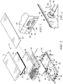
Fig. 2 is an exploded view of the support surface ofFig. 1 having an air disbursing layer, two ports, and a blower assembly positioned therein; -
Fig. 3 is a perspective view of a portion of the support surface ofFig 1 enlarged to show the a port positioned in a side of the support surface; -
Fig. 4 is a perspective view of an internal portion of the support surface showing a port conduit secured to a port; -
Fig. 5 is a perspective view of a portion of the port ofFig. 2 ; -
Fig. 6 is perspective view of a cap of the port ofFig. 2 ; -
Fig. 7 is a cross-section of the assembled port showing a tortious path for air to flow through the port into the port conduit; -
Fig. 8 is an enlarged portion ofFig. 2 showing the assembly of the blower assembly to the port conduits and ports; and -
Fig. 9 is an enlarged view of the port ofFig. 8 showing the flange of the port body welded to a lower cover of the support surface. - The referenced figures depict an embodiment of a port for a support surface designed to conduct heat and moisture away from a patient lying on a top face of the support surface by conducting air along the top face of the support surface. The design of the port reduces the potential of ingress of foreign materials from entering an air blower system attached to the port.
- The port of the depicted embodiment comprises of three components which when assembled, allows for air flow into the air blower system and directs foreign materials, such as fluids, away from the air blower system. The three components are easily assembled with interference fits. In the disclosed embodiment, the components of the port are constructed of a polymeric material. In some embodiments, the components of the port may be secured to one another by an interference fit. In other embodiments, the components may be secured through adhesives or welding, such as radio frequency (RF) welding, for example.
- An illustrative a
patient support apparatus 10 includes a support surface embodied as amattress 12 supported on ahospital bed 14 is shown inFig. 1 . Thesupport surface 12 is illustrated as a hospital mattress; however, it will be appreciated that thesupport surface 12 may be utilized for any healthcare facility or home. For example, thesupport surface 12 may be utilized in a nursing home or in a patient's own home under hospice care. Additionally, although this description is in reference to a mattress, it will be appreciated that thesupport surface 12 and devices described herein may be applicable to other support surfaces, such as chair cushions, wheelchair padding, stretchers, etc. Thesupport surface 12 may be embodied as mattress such as that disclosed as element 320 inU.S. Patent Publication No. 2019/0262201 A1 which is incorporated by reference herein for the disclosure of an air moving system capable of employing the structures recited herein as a port. - Referring to
Fig. 2 , thesupport surface 12 has several layers and includes atop cover 16, anair distribution layer 18, afire sock 20, afoam cover 22, abladder assembly 24, and alower cover 26. In addition, afoam support structure 28 includes afoot support section 30. Ablower assembly 32 is connected to theair distribution layer 18 thought afabric conduit 34 and air is forced through theair distribution layer 18 to move air along thetop cover 16 to thereby remove moisture from the inside of thetop cover 16 and cool the skin of a patient supported on thetop cover 16. The air flows out of the air distribution layer and out of themattress 12 through a number ofports 38 positioned in thelower cover 26 at the foot end and head end of thesupport surface 12. - Air flows into the
blower assembly 32 through twoports port conduits ports respective sides lower cover 26.Fig. 3 shows theport 42 from the exterior whileFig. 4 shows theport 42 from inside thelower cover 26 coupled to theport conduit 46. In some embodiments, the flow may be reversed and air may be drawn through theports 38 and theair distribution layer 18 and out of theports - The engagement of the
ports conduits blower assembly 32 is shown enlarged inFig. 8 . Theblower assembly 32 is illustrated inFig. 8 with theconduits housing 52 of theblower assembly 32. Theconduits ports connector 54 on the outboard end of eachconduit conduits respective ports - Referring to
Figs. 5-7 , eachport housing 56 andcap 58. As shown inFig. 7 , thecap 58 is positioned in apassageway 60 of thehousing 56 and is secured to thehousing 56 with an interference fit. As shown inFig. 7 , theconnector 54 is received between twoflanges cap 58 and is secured with aflange 66 of theconnector 54 being flexibly deformed to pass through thepassageway 60 inside of the twoflanges flange 66 engages a circular surface 68 (seen inFig. 5 ). - Referring to
Fig. 9 , it can be seen that aflange 74 of thehousing 56 is welded to a tickingmaterial 70 of thelower cover 26 to provide ahermetic seal 72 between the tickingmaterial 70 and the periphery of thehousing 56 at theflange 74. This prevents air from bypassing therespective port blower assembly 32 draws air through therespective port housing 52 of theblower assembly 32 and then pushed through theair distribution layer 18. - The
ports mattress 12 by theblower assembly 32 while redirecting foreign materials and reducing the potential for foreign materials to be drawn into theblower assembly 32 and pushed into thedistribution layer 18. For example, human excrement and other biomaterials, cleaning materials, dust, and spilled fluids all have the potential to drain down the side of thelower cover 26 and be drawn into theports Fig. 7 , theports tortious path 76 for air to flow from the ambient area around therespective port first stage 78 where foreign materials end to be deposited on either acircumferential surface 80 of acylindrical body 82 that defines thepassageway 60. Thecylindrical body 82 extends from aninner wall 104 of thehousing 56. Foreign materials that are vertically above thecylindrical body 82 will fall on thecircumferential surface 80 and fall, through the force of gravity around thecircumferential surface 80 and onto alower surface 84 which tends to cause the foreign material to drain down thesurface 84 and out of theport - Once the air and any contaminate passes from the
first stage 78 it enters asecond stage 86 which will again cause material to engage the interior of thecap 58 and be conducted down to the lower side of thecircumferential surface 80. The level of flow into therespective port port surfaces housing 56 of theports final stage 88 which flows directly into theblower assembly 32. - To assemble the
ports flanges cap 58, which are resiliently flexible, are deflected together as indicated byarrows 90 inFig. 6 . Theflanges passageway 60 so that therespective catches flanges back wall 96 of thehousing 56 and thereby secure thecap 58 to thehousing 56. Thecatches back wall 96. In some embodiments, thecatches back wall 96 by an interference fit only. Theconnector 54 also includes twocatches passageway 60, between theflanges cap 58 and then engage thecircular surface 68 of thehousing 56. Once in place, theconnector 54 includes abarb 102 over which therespective conduit respective conduit connector 54 to form the flow path into theblower assembly 32. During operation, air flows around thecap 58 and through thepassageway 60 andconnector 54 to supply theblower assembly 32. Due to thetortious path 76 and the overall construction of theports blower assembly 32 and other components of thesupport surface 12 is limited, thereby extending the life of the entire system. - Embodiments of the invention can be described with reference to the following numbered clauses, with preferred features laid out in the dependent clauses:
- 1. A support surface configured to conduct air along a top face of the support surface so that heat and moisture from a patient lying on the support surface are conducted away from the top face of the support surface, the support surface comprising
- a lower cover of the support surface, including an opening formed in a side of the lower cover of the support surface,
- an air distribution layer within the support surface,
- a port defining a tortious path for a flow of air through the port, the port positioned within the opening and hermetically sealed to the lower cover, the port including a housing defining a lower surface having a descending angle configured to allow gravity to conduct liquids over the lower surface away from the tortious path, and
- a blower assembly operable to draw air through the port and push air through the air distribution layer.
- 2. The support surface of clause 1, wherein the port includes a cap secured within a passageway formed in the housing, the cap including a flange that is resiliently flexible such that the flange is deflectable to be positioned through the passageway and secure to the housing with an interference fit.
- 3. The support surface of clause 2, wherein the cap includes a second flange that is also resiliently flexible such that the second flange is deflectable to be positioned through the passageway and secure to the housing with an interference fit.
- 4. The support surface of any preceding clause, wherein the port further comprises a connector secured within a passageway formed in the housing, the connector including a flange that is resiliently flexible such that the flange is deflectable to be positioned through the passageway and secure to the housing with an interference fit.
- 5. The support surface of clause 4, wherein the connector includes a second flange that is also resiliently flexible such that the second flange is deflectable to be positioned through the passageway and secure to the housing with an interference fit.
- 6. The support surface of any preceding clause, wherein the support surface further comprises a conduit extending between the connector and the blower assembly, the conduit positioned on the connector such that air that flows through the tortious path is conducted through the conduit and into the blower assembly.
- 7. A method for installing a port into a patient support surface to define a tortious path into the inner space of the patient support surface, the method comprising:
- securing a housing to a cover of the patient support surface to form a hermetic seal between the housing and the cover,
- deflecting a resiliently pliable portion of a cap to insert the deflected portion of the cap through a passageway formed in the housing from a first side of the housing, and
- permitting the resiliently pliable portion of the cap to expand to secure the cap to the housing through an interference fit, the cap overlying a portion of the passageway to form the tortious path.
- 8. The method of clause 7, further comprising deflecting a resiliently pliable portion of a connector to insert the deflected portion of the connector through the passageway from a second side of the housing, and permitting the resiliently pliable portion of the connector to expand to secure the connector to the housing through an interference fit.
- 9. The method of either clause 7 or clause 8, wherein the cover is secured to the housing by radio frequency welding.
Claims (15)
- A port for a support surface, the port comprisinga housing, the housing defines a cavity and a passageway having an outer surface, wherein the housing further includes drain surface defining a descending angle positioned in the cavity and configured to allow gravity to conduct foreign materials over the outer surface of the passageway and over the drain surface away from the cavity,a cap including a resiliently pliable received within the passageway and expanding within the housing such that the flange is secured to the housing by an interference fit, the cap and housing cooperating to define a tortious path for a flow of air through the port, anda connector, the connector having first portion for securing the connector to a conduit and a second portion, the second portion including a resiliently pliable flange received within the passageway and expanding within the housing such that the flange is secured to the housing by an interference fit.
- The port of claim 1, wherein the flange of the cap engages the back wall of the housing to secure the cap to the housing
- The port of either claim 1 or claim 2, wherein the housing includes a flange configured to engage a material about the periphery of the housing to be hermetically sealed to the material.
- The port of any preceding claim, wherein the housing includes a cylindrical body, the cylindrical body defining the passageway, the cylindrical body having a circumferential outer surface.
- The port of claim 4, wherein the cylindrical body includes a circular surface, the passageway extending between the circular surface and a back wall of the housing, the flange of the connector engaging the circular surface to secure the connector to the housing.
- The port of any preceding claim, wherein the flange of the cap is welded to the back wall of the housing to secure the cap to the housing.
- The port of any preceding claim, wherein the tortious path includes a first stage that extends between the outer ambient atmosphere and an inner wall of the housing.
- The port of claim 7, wherein the tortious path includes a second stage that extends between the inner wall of the housing and the interior of the cap, the second stage directing flow in a direction opposite the direction of flow in the first stage to thereby encourage foreign materials to be deposited at the transition between the first and second stage.
- The port of claim 8, wherein the cap has a defined width greater than the outer width of the passageway such that the cap overlaps the passageway of the housing to prevent the direct ingress of foreign materials into the passageway.
- The port of any preceding claim, wherein the flange of the cap is secured to the housing by welding the flange to the housing.
- A support surface configured to conduct air along a top face of the support surface so that heat and moisture from a patient lying on the support surface are conducted away from the top face of the support surface, the support surface comprisinga lower cover of the support surface, including an opening formed in a side of the lower cover of the support surface,an air distribution layer within the support surface,the port of any preceding claim, the port positioned within the opening and hermetically sealed to the lower cover, anda blower assembly operable to draw air through the port and push air through the air distribution layer.
- A support surface configured to conduct air along a top face of the support surface so that heat and moisture from a patient lying on the support surface are conducted away from the top face of the support surface, the support surface comprisinga lower cover of the support surface, including an opening formed in a side of the lower cover of the support surface,an air distribution layer within the support surface,a port defining a tortious path for a flow of air through the port, the port positioned within the opening and hermetically sealed to the lower cover, the port including a housing defining a lower surface having a descending angle configured to allow gravity to conduct liquids over the lower surface away from the tortious path, anda blower assembly operable to draw air through the port and push air through the air distribution layer.
- The support surface of claim 12, wherein the port includes a cap secured within a passageway formed in the housing, the cap including a flange that is resiliently flexible such that the flange is deflectable to be positioned through the passageway and secure to the housing with an interference fit.
- The support surface of either claim 12 or claim 13, wherein the cap includes a second flange that is also resiliently flexible such that the second flange is deflectable to be positioned through the passageway and secure to the housing with an interference fit.
- The support surface of any one of claims 12 to 14, wherein the port further comprises a connector secured within a passageway formed in the housing, the connector including a flange that is resiliently flexible such that the flange is deflectable to be positioned through the passageway and secure to the housing with an interference fit, and wherein preferably the connector includes a second flange that is also resiliently flexible such that the second flange is deflectable to be positioned through the passageway and secure to the housing with an interference fit.
Applications Claiming Priority (1)
| Application Number | Priority Date | Filing Date | Title |
|---|---|---|---|
| US202063118248P | 2020-11-25 | 2020-11-25 |
Publications (2)
| Publication Number | Publication Date |
|---|---|
| EP4005545A1 true EP4005545A1 (en) | 2022-06-01 |
| EP4005545B1 EP4005545B1 (en) | 2024-01-17 |
Family
ID=78789830
Family Applications (1)
| Application Number | Title | Priority Date | Filing Date |
|---|---|---|---|
| EP21210441.8A Active EP4005545B1 (en) | 2020-11-25 | 2021-11-25 | Port for an internal air distribution system of a patient support surface |
Country Status (3)
| Country | Link |
|---|---|
| US (3) | US11826295B2 (en) |
| EP (1) | EP4005545B1 (en) |
| CN (1) | CN216676209U (en) |
Families Citing this family (2)
| Publication number | Priority date | Publication date | Assignee | Title |
|---|---|---|---|---|
| US11826295B2 (en) | 2020-11-25 | 2023-11-28 | Hill-Rom Services, Inc. | Port for an internal air distribution system of a patient support surface |
| WO2024206645A2 (en) * | 2023-03-31 | 2024-10-03 | Hill-Rom Services, Inc. | Mattress with low-pressure high-flow moisture management |
Citations (4)
| Publication number | Priority date | Publication date | Assignee | Title |
|---|---|---|---|---|
| WO1993005684A1 (en) * | 1991-09-23 | 1993-04-01 | Chaffee Robert B | Pneumatic support system |
| US5249319A (en) * | 1992-09-09 | 1993-10-05 | Mellen Air Manufacturing, Inc. | Low air loss, pressure relieving mattress system |
| US20130025053A1 (en) * | 2011-07-28 | 2013-01-31 | Vrzalik John H | Multi-Layered Support System |
| US20190262201A1 (en) | 2018-02-27 | 2019-08-29 | Hill-Rom Services, Inc. | Patient support surface control, end of life indication, and x-ray cassette sleeve |
Family Cites Families (11)
| Publication number | Priority date | Publication date | Assignee | Title |
|---|---|---|---|---|
| US1865319A (en) * | 1930-09-02 | 1932-06-28 | John K Jensen | Breather pipe cap |
| US1960657A (en) * | 1932-01-20 | 1934-05-29 | Leslie A Alexander | Breather pipe cap for internal combustion engines |
| US4645521A (en) * | 1985-04-18 | 1987-02-24 | Freesh Charles W | Particulate trap |
| US5800582A (en) * | 1997-03-10 | 1998-09-01 | United Technologies Corporation | Compact water collector |
| DE10125404A1 (en) * | 2001-05-25 | 2002-11-28 | Mann & Hummel Filter | Inertial separator for cleaning gas stream has pattern of curved blades to bend gas stream and with sloping collecting surface for impurities |
| DE102004036568A1 (en) * | 2004-07-28 | 2006-02-16 | Liebherr-Aerospace Lindenberg Gmbh | Water separator for air conditioners |
| US8945285B2 (en) * | 2011-12-23 | 2015-02-03 | Valeo Climate Control | Water separator having a gutter |
| EP3236897A1 (en) * | 2014-12-23 | 2017-11-01 | 3M Innovative Properties Company | Convective system with fixation element |
| FR3033503B1 (en) * | 2015-03-10 | 2019-05-24 | Filtrauto | DEVICE FOR SEPARATING CARTER GAS OIL FROM AN INTERNAL COMBUSTION ENGINE |
| US11826295B2 (en) | 2020-11-25 | 2023-11-28 | Hill-Rom Services, Inc. | Port for an internal air distribution system of a patient support surface |
| US11697089B2 (en) * | 2021-04-28 | 2023-07-11 | Eto Magnetic Gmbh | Particulate filtration device, fuel vapor recovery system, vehicle and method for a particulate filtration |
-
2021
- 2021-11-24 US US17/534,534 patent/US11826295B2/en active Active
- 2021-11-25 CN CN202122916285.1U patent/CN216676209U/en active Active
- 2021-11-25 EP EP21210441.8A patent/EP4005545B1/en active Active
-
2023
- 2023-11-22 US US18/517,027 patent/US12343294B2/en active Active
-
2025
- 2025-06-30 US US19/254,314 patent/US20250325426A1/en active Pending
Patent Citations (4)
| Publication number | Priority date | Publication date | Assignee | Title |
|---|---|---|---|---|
| WO1993005684A1 (en) * | 1991-09-23 | 1993-04-01 | Chaffee Robert B | Pneumatic support system |
| US5249319A (en) * | 1992-09-09 | 1993-10-05 | Mellen Air Manufacturing, Inc. | Low air loss, pressure relieving mattress system |
| US20130025053A1 (en) * | 2011-07-28 | 2013-01-31 | Vrzalik John H | Multi-Layered Support System |
| US20190262201A1 (en) | 2018-02-27 | 2019-08-29 | Hill-Rom Services, Inc. | Patient support surface control, end of life indication, and x-ray cassette sleeve |
Also Published As
| Publication number | Publication date |
|---|---|
| EP4005545B1 (en) | 2024-01-17 |
| US20240082087A1 (en) | 2024-03-14 |
| US11826295B2 (en) | 2023-11-28 |
| US12343294B2 (en) | 2025-07-01 |
| CN216676209U (en) | 2022-06-07 |
| US20250325426A1 (en) | 2025-10-23 |
| US20220160559A1 (en) | 2022-05-26 |
Similar Documents
| Publication | Publication Date | Title |
|---|---|---|
| US20250325426A1 (en) | Method of installing a port into a patient support surface | |
| US10172470B1 (en) | Multi-layer support system | |
| US12064372B2 (en) | Female external urinary device and assembly | |
| JP5855748B2 (en) | Multi-layer support system | |
| JP5108874B2 (en) | Multi-layer support system | |
| JP5364153B2 (en) | SIDS prevention mattress | |
| KR20190111106A (en) | Apparatus and method for receiving excreted urine | |
| EP2662064A2 (en) | Occupant support apparatus and assembly with liquid removal and microclimate control capabilities | |
| KR20110086859A (en) | Multi-Layer Support System and Method | |
| US6158070A (en) | Coverlet for an air bed | |
| US20080083060A1 (en) | Bedpan and method for removal of the contents thereof | |
| KR102297172B1 (en) | rotatable operating table | |
| US12171704B2 (en) | Patient support including a connector assembly | |
| JP2004344320A (en) | Assembled isolation hood device | |
| US4725270A (en) | Fluid channeling pad | |
| US20170333272A1 (en) | Bed System Having Removable Bed Pan | |
| CN104739598B (en) | mattress | |
| US20250288450A1 (en) | Waste capturing device | |
| Emken | 1997 HME REsOURCE GUIDE |
Legal Events
| Date | Code | Title | Description |
|---|---|---|---|
| PUAI | Public reference made under article 153(3) epc to a published international application that has entered the european phase |
Free format text: ORIGINAL CODE: 0009012 |
|
| STAA | Information on the status of an ep patent application or granted ep patent |
Free format text: STATUS: THE APPLICATION HAS BEEN PUBLISHED |
|
| AK | Designated contracting states |
Kind code of ref document: A1 Designated state(s): AL AT BE BG CH CY CZ DE DK EE ES FI FR GB GR HR HU IE IS IT LI LT LU LV MC MK MT NL NO PL PT RO RS SE SI SK SM TR |
|
| STAA | Information on the status of an ep patent application or granted ep patent |
Free format text: STATUS: REQUEST FOR EXAMINATION WAS MADE |
|
| 17P | Request for examination filed |
Effective date: 20221201 |
|
| RBV | Designated contracting states (corrected) |
Designated state(s): AL AT BE BG CH CY CZ DE DK EE ES FI FR GB GR HR HU IE IS IT LI LT LU LV MC MK MT NL NO PL PT RO RS SE SI SK SM TR |
|
| GRAP | Despatch of communication of intention to grant a patent |
Free format text: ORIGINAL CODE: EPIDOSNIGR1 |
|
| STAA | Information on the status of an ep patent application or granted ep patent |
Free format text: STATUS: GRANT OF PATENT IS INTENDED |
|
| INTG | Intention to grant announced |
Effective date: 20230807 |
|
| RIN1 | Information on inventor provided before grant (corrected) |
Inventor name: CHURILLA, MICHAEL Inventor name: BORGMAN, DOUGLAS E. Inventor name: RAMEGOWDA, JNANESHA |
|
| GRAS | Grant fee paid |
Free format text: ORIGINAL CODE: EPIDOSNIGR3 |
|
| GRAA | (expected) grant |
Free format text: ORIGINAL CODE: 0009210 |
|
| STAA | Information on the status of an ep patent application or granted ep patent |
Free format text: STATUS: THE PATENT HAS BEEN GRANTED |
|
| AK | Designated contracting states |
Kind code of ref document: B1 Designated state(s): AL AT BE BG CH CY CZ DE DK EE ES FI FR GB GR HR HU IE IS IT LI LT LU LV MC MK MT NL NO PL PT RO RS SE SI SK SM TR |
|
| REG | Reference to a national code |
Ref country code: GB Ref legal event code: FG4D |
|
| REG | Reference to a national code |
Ref country code: DE Ref legal event code: R096 Ref document number: 602021008706 Country of ref document: DE |
|
| REG | Reference to a national code |
Ref country code: CH Ref legal event code: EP |
|
| REG | Reference to a national code |
Ref country code: IE Ref legal event code: FG4D |
|
| REG | Reference to a national code |
Ref country code: LT Ref legal event code: MG9D |
|
| REG | Reference to a national code |
Ref country code: NL Ref legal event code: MP Effective date: 20240117 |
|
| REG | Reference to a national code |
Ref country code: AT Ref legal event code: MK05 Ref document number: 1650078 Country of ref document: AT Kind code of ref document: T Effective date: 20240117 |
|
| PG25 | Lapsed in a contracting state [announced via postgrant information from national office to epo] |
Ref country code: NL Free format text: LAPSE BECAUSE OF FAILURE TO SUBMIT A TRANSLATION OF THE DESCRIPTION OR TO PAY THE FEE WITHIN THE PRESCRIBED TIME-LIMIT Effective date: 20240117 |
|
| PG25 | Lapsed in a contracting state [announced via postgrant information from national office to epo] |
Ref country code: NL Free format text: LAPSE BECAUSE OF FAILURE TO SUBMIT A TRANSLATION OF THE DESCRIPTION OR TO PAY THE FEE WITHIN THE PRESCRIBED TIME-LIMIT Effective date: 20240117 |
|
| PG25 | Lapsed in a contracting state [announced via postgrant information from national office to epo] |
Ref country code: IS Free format text: LAPSE BECAUSE OF FAILURE TO SUBMIT A TRANSLATION OF THE DESCRIPTION OR TO PAY THE FEE WITHIN THE PRESCRIBED TIME-LIMIT Effective date: 20240517 |
|
| PG25 | Lapsed in a contracting state [announced via postgrant information from national office to epo] |
Ref country code: LT Free format text: LAPSE BECAUSE OF FAILURE TO SUBMIT A TRANSLATION OF THE DESCRIPTION OR TO PAY THE FEE WITHIN THE PRESCRIBED TIME-LIMIT Effective date: 20240117 |
|
| PG25 | Lapsed in a contracting state [announced via postgrant information from national office to epo] |
Ref country code: GR Free format text: LAPSE BECAUSE OF FAILURE TO SUBMIT A TRANSLATION OF THE DESCRIPTION OR TO PAY THE FEE WITHIN THE PRESCRIBED TIME-LIMIT Effective date: 20240418 |
|
| PG25 | Lapsed in a contracting state [announced via postgrant information from national office to epo] |
Ref country code: HR Free format text: LAPSE BECAUSE OF FAILURE TO SUBMIT A TRANSLATION OF THE DESCRIPTION OR TO PAY THE FEE WITHIN THE PRESCRIBED TIME-LIMIT Effective date: 20240117 Ref country code: RS Free format text: LAPSE BECAUSE OF FAILURE TO SUBMIT A TRANSLATION OF THE DESCRIPTION OR TO PAY THE FEE WITHIN THE PRESCRIBED TIME-LIMIT Effective date: 20240417 |
|
| PG25 | Lapsed in a contracting state [announced via postgrant information from national office to epo] |
Ref country code: ES Free format text: LAPSE BECAUSE OF FAILURE TO SUBMIT A TRANSLATION OF THE DESCRIPTION OR TO PAY THE FEE WITHIN THE PRESCRIBED TIME-LIMIT Effective date: 20240117 |
|
| PG25 | Lapsed in a contracting state [announced via postgrant information from national office to epo] |
Ref country code: AT Free format text: LAPSE BECAUSE OF FAILURE TO SUBMIT A TRANSLATION OF THE DESCRIPTION OR TO PAY THE FEE WITHIN THE PRESCRIBED TIME-LIMIT Effective date: 20240117 |
|
| PG25 | Lapsed in a contracting state [announced via postgrant information from national office to epo] |
Ref country code: RS Free format text: LAPSE BECAUSE OF FAILURE TO SUBMIT A TRANSLATION OF THE DESCRIPTION OR TO PAY THE FEE WITHIN THE PRESCRIBED TIME-LIMIT Effective date: 20240417 Ref country code: NO Free format text: LAPSE BECAUSE OF FAILURE TO SUBMIT A TRANSLATION OF THE DESCRIPTION OR TO PAY THE FEE WITHIN THE PRESCRIBED TIME-LIMIT Effective date: 20240417 Ref country code: LT Free format text: LAPSE BECAUSE OF FAILURE TO SUBMIT A TRANSLATION OF THE DESCRIPTION OR TO PAY THE FEE WITHIN THE PRESCRIBED TIME-LIMIT Effective date: 20240117 Ref country code: IS Free format text: LAPSE BECAUSE OF FAILURE TO SUBMIT A TRANSLATION OF THE DESCRIPTION OR TO PAY THE FEE WITHIN THE PRESCRIBED TIME-LIMIT Effective date: 20240517 Ref country code: HR Free format text: LAPSE BECAUSE OF FAILURE TO SUBMIT A TRANSLATION OF THE DESCRIPTION OR TO PAY THE FEE WITHIN THE PRESCRIBED TIME-LIMIT Effective date: 20240117 Ref country code: GR Free format text: LAPSE BECAUSE OF FAILURE TO SUBMIT A TRANSLATION OF THE DESCRIPTION OR TO PAY THE FEE WITHIN THE PRESCRIBED TIME-LIMIT Effective date: 20240418 Ref country code: FI Free format text: LAPSE BECAUSE OF FAILURE TO SUBMIT A TRANSLATION OF THE DESCRIPTION OR TO PAY THE FEE WITHIN THE PRESCRIBED TIME-LIMIT Effective date: 20240117 Ref country code: ES Free format text: LAPSE BECAUSE OF FAILURE TO SUBMIT A TRANSLATION OF THE DESCRIPTION OR TO PAY THE FEE WITHIN THE PRESCRIBED TIME-LIMIT Effective date: 20240117 Ref country code: BG Free format text: LAPSE BECAUSE OF FAILURE TO SUBMIT A TRANSLATION OF THE DESCRIPTION OR TO PAY THE FEE WITHIN THE PRESCRIBED TIME-LIMIT Effective date: 20240117 Ref country code: AT Free format text: LAPSE BECAUSE OF FAILURE TO SUBMIT A TRANSLATION OF THE DESCRIPTION OR TO PAY THE FEE WITHIN THE PRESCRIBED TIME-LIMIT Effective date: 20240117 |
|
| PG25 | Lapsed in a contracting state [announced via postgrant information from national office to epo] |
Ref country code: PL Free format text: LAPSE BECAUSE OF FAILURE TO SUBMIT A TRANSLATION OF THE DESCRIPTION OR TO PAY THE FEE WITHIN THE PRESCRIBED TIME-LIMIT Effective date: 20240117 Ref country code: PT Free format text: LAPSE BECAUSE OF FAILURE TO SUBMIT A TRANSLATION OF THE DESCRIPTION OR TO PAY THE FEE WITHIN THE PRESCRIBED TIME-LIMIT Effective date: 20240517 |
|
| PG25 | Lapsed in a contracting state [announced via postgrant information from national office to epo] |
Ref country code: SE Free format text: LAPSE BECAUSE OF FAILURE TO SUBMIT A TRANSLATION OF THE DESCRIPTION OR TO PAY THE FEE WITHIN THE PRESCRIBED TIME-LIMIT Effective date: 20240117 Ref country code: PT Free format text: LAPSE BECAUSE OF FAILURE TO SUBMIT A TRANSLATION OF THE DESCRIPTION OR TO PAY THE FEE WITHIN THE PRESCRIBED TIME-LIMIT Effective date: 20240517 Ref country code: PL Free format text: LAPSE BECAUSE OF FAILURE TO SUBMIT A TRANSLATION OF THE DESCRIPTION OR TO PAY THE FEE WITHIN THE PRESCRIBED TIME-LIMIT Effective date: 20240117 Ref country code: LV Free format text: LAPSE BECAUSE OF FAILURE TO SUBMIT A TRANSLATION OF THE DESCRIPTION OR TO PAY THE FEE WITHIN THE PRESCRIBED TIME-LIMIT Effective date: 20240117 |
|
| PG25 | Lapsed in a contracting state [announced via postgrant information from national office to epo] |
Ref country code: DK Free format text: LAPSE BECAUSE OF FAILURE TO SUBMIT A TRANSLATION OF THE DESCRIPTION OR TO PAY THE FEE WITHIN THE PRESCRIBED TIME-LIMIT Effective date: 20240117 |
|
| PG25 | Lapsed in a contracting state [announced via postgrant information from national office to epo] |
Ref country code: SM Free format text: LAPSE BECAUSE OF FAILURE TO SUBMIT A TRANSLATION OF THE DESCRIPTION OR TO PAY THE FEE WITHIN THE PRESCRIBED TIME-LIMIT Effective date: 20240117 |
|
| REG | Reference to a national code |
Ref country code: DE Ref legal event code: R097 Ref document number: 602021008706 Country of ref document: DE |
|
| PG25 | Lapsed in a contracting state [announced via postgrant information from national office to epo] |
Ref country code: CZ Free format text: LAPSE BECAUSE OF FAILURE TO SUBMIT A TRANSLATION OF THE DESCRIPTION OR TO PAY THE FEE WITHIN THE PRESCRIBED TIME-LIMIT Effective date: 20240117 Ref country code: EE Free format text: LAPSE BECAUSE OF FAILURE TO SUBMIT A TRANSLATION OF THE DESCRIPTION OR TO PAY THE FEE WITHIN THE PRESCRIBED TIME-LIMIT Effective date: 20240117 |
|
| PG25 | Lapsed in a contracting state [announced via postgrant information from national office to epo] |
Ref country code: SK Free format text: LAPSE BECAUSE OF FAILURE TO SUBMIT A TRANSLATION OF THE DESCRIPTION OR TO PAY THE FEE WITHIN THE PRESCRIBED TIME-LIMIT Effective date: 20240117 |
|
| PG25 | Lapsed in a contracting state [announced via postgrant information from national office to epo] |
Ref country code: SM Free format text: LAPSE BECAUSE OF FAILURE TO SUBMIT A TRANSLATION OF THE DESCRIPTION OR TO PAY THE FEE WITHIN THE PRESCRIBED TIME-LIMIT Effective date: 20240117 Ref country code: SK Free format text: LAPSE BECAUSE OF FAILURE TO SUBMIT A TRANSLATION OF THE DESCRIPTION OR TO PAY THE FEE WITHIN THE PRESCRIBED TIME-LIMIT Effective date: 20240117 Ref country code: RO Free format text: LAPSE BECAUSE OF FAILURE TO SUBMIT A TRANSLATION OF THE DESCRIPTION OR TO PAY THE FEE WITHIN THE PRESCRIBED TIME-LIMIT Effective date: 20240117 Ref country code: EE Free format text: LAPSE BECAUSE OF FAILURE TO SUBMIT A TRANSLATION OF THE DESCRIPTION OR TO PAY THE FEE WITHIN THE PRESCRIBED TIME-LIMIT Effective date: 20240117 Ref country code: DK Free format text: LAPSE BECAUSE OF FAILURE TO SUBMIT A TRANSLATION OF THE DESCRIPTION OR TO PAY THE FEE WITHIN THE PRESCRIBED TIME-LIMIT Effective date: 20240117 Ref country code: CZ Free format text: LAPSE BECAUSE OF FAILURE TO SUBMIT A TRANSLATION OF THE DESCRIPTION OR TO PAY THE FEE WITHIN THE PRESCRIBED TIME-LIMIT Effective date: 20240117 |
|
| PLBE | No opposition filed within time limit |
Free format text: ORIGINAL CODE: 0009261 |
|
| STAA | Information on the status of an ep patent application or granted ep patent |
Free format text: STATUS: NO OPPOSITION FILED WITHIN TIME LIMIT |
|
| PG25 | Lapsed in a contracting state [announced via postgrant information from national office to epo] |
Ref country code: IT Free format text: LAPSE BECAUSE OF FAILURE TO SUBMIT A TRANSLATION OF THE DESCRIPTION OR TO PAY THE FEE WITHIN THE PRESCRIBED TIME-LIMIT Effective date: 20240117 |
|
| 26N | No opposition filed |
Effective date: 20241018 |
|
| PG25 | Lapsed in a contracting state [announced via postgrant information from national office to epo] |
Ref country code: IT Free format text: LAPSE BECAUSE OF FAILURE TO SUBMIT A TRANSLATION OF THE DESCRIPTION OR TO PAY THE FEE WITHIN THE PRESCRIBED TIME-LIMIT Effective date: 20240117 |
|
| PG25 | Lapsed in a contracting state [announced via postgrant information from national office to epo] |
Ref country code: SI Free format text: LAPSE BECAUSE OF FAILURE TO SUBMIT A TRANSLATION OF THE DESCRIPTION OR TO PAY THE FEE WITHIN THE PRESCRIBED TIME-LIMIT Effective date: 20240117 |
|
| REG | Reference to a national code |
Ref country code: CH Ref legal event code: PL |
|
| PG25 | Lapsed in a contracting state [announced via postgrant information from national office to epo] |
Ref country code: MC Free format text: LAPSE BECAUSE OF FAILURE TO SUBMIT A TRANSLATION OF THE DESCRIPTION OR TO PAY THE FEE WITHIN THE PRESCRIBED TIME-LIMIT Effective date: 20240117 |
|
| PG25 | Lapsed in a contracting state [announced via postgrant information from national office to epo] |
Ref country code: LU Free format text: LAPSE BECAUSE OF NON-PAYMENT OF DUE FEES Effective date: 20241125 |
|
| REG | Reference to a national code |
Ref country code: CH Ref legal event code: PL |
|
| PG25 | Lapsed in a contracting state [announced via postgrant information from national office to epo] |
Ref country code: CH Free format text: LAPSE BECAUSE OF NON-PAYMENT OF DUE FEES Effective date: 20241130 |
|
| REG | Reference to a national code |
Ref country code: BE Ref legal event code: MM Effective date: 20241130 |
|
| PG25 | Lapsed in a contracting state [announced via postgrant information from national office to epo] |
Ref country code: BE Free format text: LAPSE BECAUSE OF NON-PAYMENT OF DUE FEES Effective date: 20241130 |
|
| PG25 | Lapsed in a contracting state [announced via postgrant information from national office to epo] |
Ref country code: IE Free format text: LAPSE BECAUSE OF NON-PAYMENT OF DUE FEES Effective date: 20241125 |
|
| PGFP | Annual fee paid to national office [announced via postgrant information from national office to epo] |
Ref country code: DE Payment date: 20251022 Year of fee payment: 5 |
|
| PGFP | Annual fee paid to national office [announced via postgrant information from national office to epo] |
Ref country code: GB Payment date: 20251022 Year of fee payment: 5 |
|
| PGFP | Annual fee paid to national office [announced via postgrant information from national office to epo] |
Ref country code: FR Payment date: 20251022 Year of fee payment: 5 |
|
| PG25 | Lapsed in a contracting state [announced via postgrant information from national office to epo] |
Ref country code: HU Free format text: LAPSE BECAUSE OF FAILURE TO SUBMIT A TRANSLATION OF THE DESCRIPTION OR TO PAY THE FEE WITHIN THE PRESCRIBED TIME-LIMIT; INVALID AB INITIO Effective date: 20211125 |
|
| PG25 | Lapsed in a contracting state [announced via postgrant information from national office to epo] |
Ref country code: CY Free format text: LAPSE BECAUSE OF FAILURE TO SUBMIT A TRANSLATION OF THE DESCRIPTION OR TO PAY THE FEE WITHIN THE PRESCRIBED TIME-LIMIT; INVALID AB INITIO Effective date: 20211125 |
|
| PG25 | Lapsed in a contracting state [announced via postgrant information from national office to epo] |
Ref country code: TR Free format text: LAPSE BECAUSE OF FAILURE TO SUBMIT A TRANSLATION OF THE DESCRIPTION OR TO PAY THE FEE WITHIN THE PRESCRIBED TIME-LIMIT Effective date: 20240117 |