EP4005516A1 - Single frequency switch mode power supply generator with phase shifter - Google Patents
Single frequency switch mode power supply generator with phase shifter Download PDFInfo
- Publication number
- EP4005516A1 EP4005516A1 EP21210100.0A EP21210100A EP4005516A1 EP 4005516 A1 EP4005516 A1 EP 4005516A1 EP 21210100 A EP21210100 A EP 21210100A EP 4005516 A1 EP4005516 A1 EP 4005516A1
- Authority
- EP
- European Patent Office
- Prior art keywords
- voltage
- switched
- voltage signal
- ablation
- mode amplifiers
- Prior art date
- Legal status (The legal status is an assumption and is not a legal conclusion. Google has not performed a legal analysis and makes no representation as to the accuracy of the status listed.)
- Granted
Links
Images

Classifications
-
- A—HUMAN NECESSITIES
- A61—MEDICAL OR VETERINARY SCIENCE; HYGIENE
- A61B—DIAGNOSIS; SURGERY; IDENTIFICATION
- A61B18/00—Surgical instruments, devices or methods for transferring non-mechanical forms of energy to or from the body
- A61B18/04—Surgical instruments, devices or methods for transferring non-mechanical forms of energy to or from the body by heating
- A61B18/12—Surgical instruments, devices or methods for transferring non-mechanical forms of energy to or from the body by heating by passing a current through the tissue to be heated, e.g. high-frequency current
- A61B18/1206—Generators therefor
-
- A—HUMAN NECESSITIES
- A61—MEDICAL OR VETERINARY SCIENCE; HYGIENE
- A61B—DIAGNOSIS; SURGERY; IDENTIFICATION
- A61B18/00—Surgical instruments, devices or methods for transferring non-mechanical forms of energy to or from the body
- A61B18/04—Surgical instruments, devices or methods for transferring non-mechanical forms of energy to or from the body by heating
- A61B18/12—Surgical instruments, devices or methods for transferring non-mechanical forms of energy to or from the body by heating by passing a current through the tissue to be heated, e.g. high-frequency current
- A61B18/14—Probes or electrodes therefor
-
- A—HUMAN NECESSITIES
- A61—MEDICAL OR VETERINARY SCIENCE; HYGIENE
- A61B—DIAGNOSIS; SURGERY; IDENTIFICATION
- A61B18/00—Surgical instruments, devices or methods for transferring non-mechanical forms of energy to or from the body
- A61B18/04—Surgical instruments, devices or methods for transferring non-mechanical forms of energy to or from the body by heating
- A61B18/12—Surgical instruments, devices or methods for transferring non-mechanical forms of energy to or from the body by heating by passing a current through the tissue to be heated, e.g. high-frequency current
- A61B18/14—Probes or electrodes therefor
- A61B18/1492—Probes or electrodes therefor having a flexible, catheter-like structure, e.g. for heart ablation
-
- A—HUMAN NECESSITIES
- A61—MEDICAL OR VETERINARY SCIENCE; HYGIENE
- A61B—DIAGNOSIS; SURGERY; IDENTIFICATION
- A61B34/00—Computer-aided surgery; Manipulators or robots specially adapted for use in surgery
- A61B34/20—Surgical navigation systems; Devices for tracking or guiding surgical instruments, e.g. for frameless stereotaxis
-
- H—ELECTRICITY
- H02—GENERATION; CONVERSION OR DISTRIBUTION OF ELECTRIC POWER
- H02M—APPARATUS FOR CONVERSION BETWEEN AC AND AC, BETWEEN AC AND DC, OR BETWEEN DC AND DC, AND FOR USE WITH MAINS OR SIMILAR POWER SUPPLY SYSTEMS; CONVERSION OF DC OR AC INPUT POWER INTO SURGE OUTPUT POWER; CONTROL OR REGULATION THEREOF
- H02M7/00—Conversion of AC power input into DC power output; Conversion of DC power input into AC power output
- H02M7/42—Conversion of DC power input into AC power output without possibility of reversal
- H02M7/44—Conversion of DC power input into AC power output without possibility of reversal by static converters
- H02M7/48—Conversion of DC power input into AC power output without possibility of reversal by static converters using discharge tubes with control electrode or semiconductor devices with control electrode
-
- H—ELECTRICITY
- H03—ELECTRONIC CIRCUITRY
- H03F—AMPLIFIERS
- H03F3/00—Amplifiers with only discharge tubes or only semiconductor devices as amplifying elements
- H03F3/20—Power amplifiers, e.g. Class B amplifiers, Class C amplifiers
- H03F3/21—Power amplifiers, e.g. Class B amplifiers, Class C amplifiers with semiconductor devices only
- H03F3/211—Power amplifiers, e.g. Class B amplifiers, Class C amplifiers with semiconductor devices only using a combination of several amplifiers
-
- A—HUMAN NECESSITIES
- A61—MEDICAL OR VETERINARY SCIENCE; HYGIENE
- A61B—DIAGNOSIS; SURGERY; IDENTIFICATION
- A61B17/00—Surgical instruments, devices or methods
- A61B2017/00681—Aspects not otherwise provided for
- A61B2017/00734—Aspects not otherwise provided for battery operated
-
- A—HUMAN NECESSITIES
- A61—MEDICAL OR VETERINARY SCIENCE; HYGIENE
- A61B—DIAGNOSIS; SURGERY; IDENTIFICATION
- A61B18/00—Surgical instruments, devices or methods for transferring non-mechanical forms of energy to or from the body
- A61B2018/00315—Surgical instruments, devices or methods for transferring non-mechanical forms of energy to or from the body for treatment of particular body parts
- A61B2018/00345—Vascular system
- A61B2018/00351—Heart
-
- A—HUMAN NECESSITIES
- A61—MEDICAL OR VETERINARY SCIENCE; HYGIENE
- A61B—DIAGNOSIS; SURGERY; IDENTIFICATION
- A61B18/00—Surgical instruments, devices or methods for transferring non-mechanical forms of energy to or from the body
- A61B2018/00571—Surgical instruments, devices or methods for transferring non-mechanical forms of energy to or from the body for achieving a particular surgical effect
- A61B2018/00577—Ablation
-
- A—HUMAN NECESSITIES
- A61—MEDICAL OR VETERINARY SCIENCE; HYGIENE
- A61B—DIAGNOSIS; SURGERY; IDENTIFICATION
- A61B18/00—Surgical instruments, devices or methods for transferring non-mechanical forms of energy to or from the body
- A61B2018/00636—Sensing and controlling the application of energy
- A61B2018/00696—Controlled or regulated parameters
- A61B2018/00702—Power or energy
-
- A—HUMAN NECESSITIES
- A61—MEDICAL OR VETERINARY SCIENCE; HYGIENE
- A61B—DIAGNOSIS; SURGERY; IDENTIFICATION
- A61B18/00—Surgical instruments, devices or methods for transferring non-mechanical forms of energy to or from the body
- A61B2018/00636—Sensing and controlling the application of energy
- A61B2018/00696—Controlled or regulated parameters
- A61B2018/0075—Phase
-
- A—HUMAN NECESSITIES
- A61—MEDICAL OR VETERINARY SCIENCE; HYGIENE
- A61B—DIAGNOSIS; SURGERY; IDENTIFICATION
- A61B18/00—Surgical instruments, devices or methods for transferring non-mechanical forms of energy to or from the body
- A61B2018/00636—Sensing and controlling the application of energy
- A61B2018/00696—Controlled or regulated parameters
- A61B2018/00767—Voltage
-
- A—HUMAN NECESSITIES
- A61—MEDICAL OR VETERINARY SCIENCE; HYGIENE
- A61B—DIAGNOSIS; SURGERY; IDENTIFICATION
- A61B18/00—Surgical instruments, devices or methods for transferring non-mechanical forms of energy to or from the body
- A61B18/04—Surgical instruments, devices or methods for transferring non-mechanical forms of energy to or from the body by heating
- A61B18/12—Surgical instruments, devices or methods for transferring non-mechanical forms of energy to or from the body by heating by passing a current through the tissue to be heated, e.g. high-frequency current
- A61B18/1206—Generators therefor
- A61B2018/1293—Generators therefor having means to prevent interference
-
- A—HUMAN NECESSITIES
- A61—MEDICAL OR VETERINARY SCIENCE; HYGIENE
- A61B—DIAGNOSIS; SURGERY; IDENTIFICATION
- A61B18/00—Surgical instruments, devices or methods for transferring non-mechanical forms of energy to or from the body
- A61B18/04—Surgical instruments, devices or methods for transferring non-mechanical forms of energy to or from the body by heating
- A61B18/12—Surgical instruments, devices or methods for transferring non-mechanical forms of energy to or from the body by heating by passing a current through the tissue to be heated, e.g. high-frequency current
- A61B18/14—Probes or electrodes therefor
- A61B2018/1467—Probes or electrodes therefor using more than two electrodes on a single probe
-
- A—HUMAN NECESSITIES
- A61—MEDICAL OR VETERINARY SCIENCE; HYGIENE
- A61B—DIAGNOSIS; SURGERY; IDENTIFICATION
- A61B34/00—Computer-aided surgery; Manipulators or robots specially adapted for use in surgery
- A61B34/20—Surgical navigation systems; Devices for tracking or guiding surgical instruments, e.g. for frameless stereotaxis
- A61B2034/2046—Tracking techniques
- A61B2034/2051—Electromagnetic tracking systems
Definitions
- the location of the medical tool in three-dimensional (3-D) space within patient anatomy is determined using electromagnetic navigation, which includes electromagnetic emitters and electromagnetic sensors on the tool to determine the tool's location. Based on the determined location, anatomical information of the patient is displayed to medical personnel. Dynamic maps of the patient anatomy (e.g., organs) are created to facilitate accurate determination of regions for ablation. Target ablation sites (i.e., regions of interest (ROI)) of an organ are identified by viewing the maps. Based on the identified ablation sites, an ablation procedure, which includes one or more ablations, is performed on the organ.
- electromagnetic navigation which includes electromagnetic emitters and electromagnetic sensors on the tool to determine the tool's location.
- anatomical information of the patient is displayed to medical personnel.
- Dynamic maps of the patient anatomy e.g., organs
- Target ablation sites i.e., regions of interest (ROI)
- ROI regions of interest
- the I/O interface 42 may enable the control console 24 to interact with the tool 22, the body surface electrodes 46 and the position sensors (not shown). Based on the electrical impulses received from the body surface electrodes 46 and the electrical signals received from the tool 22 via the I/O interface 42 and other components of medical system 20, the signal processor 40 may determine the locations of the catheter and sheath of the tool 22 in 3-D space and generate the display information 52, which may be shown on a display 50.
- the processing device 204 receives the ablation parameter data corresponding to the ablation parameter signals and generates, from the ablation parameter data, first object information for displaying a first geometrical object having a first size which represents an estimated depth of the ablation of the organ. Processing device 204 also receives, from the ablation parameter data, second object information for displaying, concurrently with the first geometrical object, a second geometrical object having a second size which represents an estimated width of the ablation of the organ.
- Display device 206 may include one or more displays each configured to display one or more maps of the organ.
- display device 206 is configured to display maps representing a spatio-temporal manifestation of an organ (e.g., a heart) as well as geometrical objects which represent estimated ablation depths and widths.
- Display device 206 may be in wired or wireless communication with processing device 204. In some embodiments, display device may be separate from computing device 214.
- the N-channel MOSFET transistors 404 are controlled, by processor 304, to switch between different states to convert the DC signal into amplitude pulses. These pulses are amplified via transformer 405 to provide the digital AC voltage signal 406 in the form of square wave (e.g., at a frequency of 480kHz).
- switched-mode amplifiers 308 are set in FIG. 3 , one or more linear power amplifiers can be utilized in an alternative embodiment. Such operational amplifiers are well known to those of skill in the art.
Landscapes
- Health & Medical Sciences (AREA)
- Engineering & Computer Science (AREA)
- Surgery (AREA)
- Life Sciences & Earth Sciences (AREA)
- Molecular Biology (AREA)
- Public Health (AREA)
- Nuclear Medicine, Radiotherapy & Molecular Imaging (AREA)
- Biomedical Technology (AREA)
- Heart & Thoracic Surgery (AREA)
- Medical Informatics (AREA)
- Veterinary Medicine (AREA)
- Animal Behavior & Ethology (AREA)
- General Health & Medical Sciences (AREA)
- Physics & Mathematics (AREA)
- Plasma & Fusion (AREA)
- Otolaryngology (AREA)
- Power Engineering (AREA)
- Cardiology (AREA)
- Robotics (AREA)
- Surgical Instruments (AREA)
- Control Of Eletrric Generators (AREA)
Abstract
Description
- Conventional ablation methods and systems, such as radio-frequency (RF) catheter ablation, are used to ablate portions of dysfunctional tissue, such as tissue of a heart, lung, ear, nose, throat or other organs of patient anatomy. For example, during a medical procedure, such as an RF catheter ablation procedure, a catheter is typically inserted through an incision in the skin and guiding the catheter to an organ where the catheter is used to create ablation lesions on the organ tissue.
- The location of the medical tool in three-dimensional (3-D) space within patient anatomy is determined using electromagnetic navigation, which includes electromagnetic emitters and electromagnetic sensors on the tool to determine the tool's location. Based on the determined location, anatomical information of the patient is displayed to medical personnel. Dynamic maps of the patient anatomy (e.g., organs) are created to facilitate accurate determination of regions for ablation. Target ablation sites (i.e., regions of interest (ROI)) of an organ are identified by viewing the maps. Based on the identified ablation sites, an ablation procedure, which includes one or more ablations, is performed on the organ.
- A more detailed understanding can be had from the following description, given by way of example in conjunction with the accompanying drawings wherein:
-
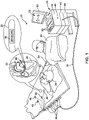
FIG. 1 is an illustration of an example medical system for navigating a tool in 3-D space according to embodiments disclosed herein; -
FIG. 2 is an illustration of components of an example electromagnetic navigation system for use with embodiments described herein; -
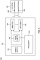
FIG. 3 is a diagram of components of a medical tool, including a switch mode power supply generator which operates on a signal frequency, which can be used to implement features of the present disclosure; and -
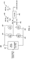
FIG. 4 is a diagram of components of a medical tool, including a Class D inverter power amplifier, which can be used to implement features of the present disclosure. -
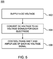
FIG. 5 is a flow diagram illustrating an example method of controlling power supplied for a medical ablation procedure. - The methods and systems conventionally used to identify ablation sites and perform the ablation procedure are time consuming (e.g., several hours) and rely on medical personnel with specific expertise and experience (typically requiring many hours of training). Successful treatment depends on accurate identification of ablation sites as well as an accurate assessment of the ablations performed on the organ.
- Typically, ablation is performed by applying RF energy to an organ via multiple electrodes of a medical tool, such as a catheter. Radiofrequency (RF) generators are used to supply power to the electrodes of the medical tool for the ablation.
- Conventional RF generators include linear power supplies which apply AC voltage to a transformer to change (e.g., step down) the voltage before being applied to a regulator to regulate the voltage. The components (e.g., transformer and regulator circuitry) of these conventional linear power supplies used to regulate the voltage are relatively large and generate more heat, resulting in lower energy efficiency. For example, conventional linear power supply generators have limited power yield (e.g., 25 watts of RF energy) and require high amounts of power to ablate.
- In addition, for multi-catheter ablation, conventional RF generators control the power supplied to each electrode by driving the electrodes with signals having distinct frequencies, resulting in the presence of intermodulation distortion (IMD). IMD occurs when multiple signals of different frequencies are mixed together and additional signals are formed at frequencies that are not, in general, at harmonic frequencies of either signal. Accordingly, the IMD can cause the ablation signals to interfere with other signals, such as electrocardiogram (ECG) signals.
- The present application provides a medical tool, such as a catheter, which includes a switched-mode power supply generator that operates on a single frequency. The power generator includes a plurality of switched-mode type amplifiers, each electrically connected to one of a plurality of ablation electrodes of a medical tool, such as a catheter. In contrast to conventional linear power supply RF generators, the switched-mode power supply RF generator converts the AC power directly into a DC voltage without the use of a transformer. Accordingly, the switched-mode power supply generator is smaller and more efficient (e.g., higher power conversion ratio) than conventional linear power supply generators used for RF ablation.
- In addition, the switched-mode power supply generators disclosed herein control the supply power to the electrodes by an applied voltage and phase shift. That is, the amplitude is controlled for the signals output to each of the electrodes at the same frequency but with different phase shifts to control the power yielded by each electrode. Because the power is controlled using a single frequency, IMD is not present and the ablation signals do not interfere with other signals.
- The present application discloses a power generator for use with a medical tool used to perform a medical ablation procedure. The power generator comprises a power supply configured to generate a DC voltage, a phase shifter configured to shift signal transmission phase angles, a plurality of switched-mode amplifiers each configured to convert the DC voltage received from the power supply to an AC voltage signal. The power generator also comprises a processor configured to control a phase shift of each AC voltage signal converted by the switched-mode amplifiers and an amplitude of each AC voltage signal converted by the switched-mode amplifiers.
- The present application discloses a system used to perform a medical ablation procedure. The system comprises a medical tool comprising a plurality of electrodes used to apply radio frequency (RF) energy for ablating tissue and a power generator a power supply configured to generate a DC voltage. The power generator comprises a power supply configured to generate a DC voltage, a phase shifter configured to shift signal transmission phase angles and a plurality of switched-mode amplifiers each electrically connected to a corresponding one of the electrodes and each configured to convert the DC voltage received from the power supply to an AC voltage signal provided to the corresponding electrode. The power generator also comprises a processor configured to control the power yielded by each electrode by controlling a phase shift of each AC voltage signal converted by the switched-mode amplifiers and controlling amplitude of each AC voltage signal convert by the switched-mode amplifiers.
- The present application discloses a method of controlling power supplied for a medical ablation procedure. The method comprises supplying a DC voltage, converting, by each one of a plurality of switched-mode amplifiers, the DC voltage to a corresponding AC voltage signal, controlling a phase shift of each AC voltage signal converted by the switched-mode amplifiers and controlling an amplitude of each AC voltage signal convert by the switched-mode amplifiers.
- Referring now to
FIG. 1 , an illustration of an examplemedical system 20 is shown that may be used to generate and display information 52 (e.g., a chart, anatomical models of a portion of a patient and signal information). Tools (i.e., medical tools), such astool 22, can be any tool which includes a catheter and a sheath (e.g., steerable and deflectable sheath) used for diagnostic or therapeutic treatment, such as for mapping electrical potentials in aheart 26 of apatient 28. Alternatively, tools may be used, mutatis mutandis, for other therapeutic and/or diagnostic purposes of different portions of anatomy, such as in the heart, lungs or other body organs, such as the ear, nose, and throat (ENT). Tools may include, for example, probes, catheters, cutting tools and suction devices. - An
operator 30 may insert thetool 22 into a portion of patient anatomy, such as the vascular system of thepatient 28 so that atip 56 of thetool 22 enters a chamber of theheart 26. Thecontrol console 24 may use magnetic position sensing to determine position coordinates of the tool (e.g., coordinates of the tip 56) in 3-D space inside theheart 26. As described in more detail below, magnetic position sensing is used to determine the location of both a catheter and a sheath of thetool 22 in 3-D space. To determine the position coordinates, adriver circuit 34 in thecontrol console 24 may drive, via connector, 44,field generators 36 to generate magnetic fields within the anatomy of thepatient 28. - The
field generators 36 include one or more emitter coils (not shown inFIG. 1 ), placed at known positions external to thepatient 28, which are configured to generate magnetic fields in a predefined working volume that contains a portion of interest of the patient anatomy. Each of the emitting coils is driven by a different frequency to emit a constant magnetic field in 3-D space. For example, in the examplemedical system 20 shown inFIG. 1 , one or more emitter coils can be placed below the torso of thepatient 28 and each configured to generate magnetic fields in a predefined working volume that contains theheart 26 of the patient. - One or more electromagnetic sensors (i.e., magnetic field location sensors) 38 are disposed on a catheter of the
tool 22 which generate electrical signals based on the amplitude and phase of the magnetic fields to determine the position of the catheter in 3-D space. As described in more detail below, three separateelectromagnetic sensors 38 are also disposed on a sheath of thetool 22 to accurately determine the location of the sheath using electromagnetic based navigation. - The signals are wirelessly communicated to the
control console 24 via a wireless communication interface (e.g., interface 312 shown atFIG. 3 ) at thetool 22 that may communicate with a corresponding input/output (I/O)interface 42 in thecontrol console 24. The wireless communication interface 312 and the I/O interface 42 may operate in accordance with any suitable wireless communication standard that is known in the art, such as for example, infrared (IR), radio frequency (RF), Bluetooth, one of the IEEE 802.11 family of standards (e.g., Wi-Fi), or the HiperLAN standard. Thebody surface electrodes 46 may include one or more wireless sensor nodes integrated on a flexible substrate. The one or more wireless sensor nodes may include a wireless transmit/receive unit (WTRU) enabling local digital signal processing, a radio link, and a miniaturized rechargeable battery, as described in more detail below. - The I/
O interface 42 may enable thecontrol console 24 to interact with thetool 22, thebody surface electrodes 46 and the position sensors (not shown). Based on the electrical impulses received from thebody surface electrodes 46 and the electrical signals received from thetool 22 via the I/O interface 42 and other components ofmedical system 20, thesignal processor 40 may determine the locations of the catheter and sheath of thetool 22 in 3-D space and generate thedisplay information 52, which may be shown on adisplay 50. - The
signal processor 40 is configured to process the signals to determine the position coordinates of both the catheter and sheath of thetool 22 in 3-D space, including both location and orientation coordinates. Each of the magneticfield location sensors 38 transmit a signal to thecontrol console 24 which indicates location coordinates of the tool 22 (e.g., location coordinates of the catheter and sheath of the tool 22) in 3-D space. - The
signal processor 40 may be included in a general-purpose computer, with a suitable front end and interface circuits for receiving signals from thetool 22 and controlling the other components of thecontrol console 24. Thesignal processor 40 may be programmed, using software, to perform the functions that are described herein. The software may be downloaded to thecontrol console 24 in electronic form, over a network, for example, or it may be provided on non-transitory tangible media, such as optical, magnetic or electronic memory media. Alternatively, some or all of the functions of thesignal processor 40 may be performed by dedicated or programmable digital hardware components. - In the example shown at
FIG. 1 , thecontrol console 24 is connected, viacable 44, tobody surface electrodes 46, each of which are attached topatient 28 using patches (e.g., indicated inFIG. 1 as circles around the electrodes 46) that adhere to the skin of the patient. In addition or alternative to the patches,body surface electrodes 46 may also be positioned on the patient using articles worn bypatient 28 which include thebody surface electrodes 46 and may also include one or more position sensors (not shown) indicating the location of the worn article. For example,body surface electrodes 46 can be embedded in a vest that is configured to be worn by thepatient 28. During operation, thebody surface electrodes 46 assist in providing a location of the tool (e.g., catheter) in 3-D space by detecting electrical impulses generated by the polarization and depolarization of cardiac tissue and transmitting information to thecontrol console 24, via thecable 44. Thebody surface electrodes 46 can be equipped with magnetic location tracking and can help identify and track the respiration cycle of thepatient 28. - Additionally or alternatively, the
tool 22, thebody surface electrodes 46 and other sensors (not shown) may communicate with thecontrol console 24 and one another via a wireless interface. For example, a wireless catheter, which is not physically connected to signal processing and/or computing apparatus, can communicate with thecontrol console 24. For example, a transmitter/receiver is attached to the catheter which communicates with a signal processing and/or computer apparatus using wireless communication methods, such as IR, RF, Bluetooth, or acoustic transmissions. - During the diagnostic treatment, the
signal processor 40 may present thedisplay information 52 and may store data representing theinformation 52 in amemory 58. Thememory 58 may include any suitable volatile and/or non-volatile memory, such as random access memory or a hard disk drive. Theoperator 30 may be able to manipulate thedisplay information 52 using one ormore input devices 59. Alternatively, themedical system 20 may include a second operator that manipulates thecontrol console 24 while theoperator 30 manipulates thetool 22. It should be noted that the configuration shown inFIG. 1 is exemplary. Any suitable configuration of themedical system 20 may be used and implemented. -
FIG. 2 is a block diagram illustrating example components of amedical system 200 for use with embodiments described herein. As shown inFIG. 2 , thesystem 200 includes amedical tool 201, aprocessing device 204, adisplay device 206 andmemory 212. Themedical tool 201 includes acatheter 202 and asheath 220. Thecatheter 202 is, for example, an ablation catheter used to ablate portions (e.g., tissue) in patient anatomy. Thesheath 220 is, for example, steerable and deflectable to facilitate, for example, catheter access, stability, and tissue contact in target sites within patient anatomy. For example, during operation thecatheter 202 is guided within patient anatomy (e.g., via a blood vessel) through the steerable anddeflectable sheath 220 to a target location (e.g., a heart). - As shown in
FIG. 2 , theprocessing device 204,display device 206 andmemory 212 are a part of anexample computing device 214. In some embodiments, thedisplay device 206 may be separate fromcomputing device 214.Computing device 214 may also include an I/O interface, such as I/O interface 42 shown inFIG. 1 . - As shown in
FIG. 2 , theexample catheter 202 includes one ormore sensors 216, which include, for example, a magnetic field location sensor (e.g.,sensor 38 inFIG. 1 ) for providing location signals to indicate the 3-D position coordinates of thecatheter 202. Likewise, theexample sheath 220 includes one ormore sensors 218, which include, for example, a magnetic field location sensor for providing location signals to indicate the 3-D position coordinates of thesheath 220. In some procedures, one or moreadditional sensors 210 that are separate from thecatheter 202, as shown inexample system 200, are also used to provide location signals. In some embodiments, thecatheter 202 also includescatheter electrodes 208 for mapping electrical potentials of a heart. - Sensors 216 (and 218) may also include, for example, position sensors, pressure or force sensors, temperature sensors, impedance sensors or other sensors which provide ablation parameter signals indicating ablation parameters during the ablation of tissue of an organ. During the ablation procedure,
RF generator 230 supplies high-frequency electrical energy, viacatheter 202, for ablating tissue at locations engaged by thecatheter 202.Sensors catheter 202 orsheath 220 position stability, temperature, ablation time, ablation power and ablation impedance) during the ablation procedure.Catheter 202 orsheath 220 may be in wired or wireless communication withprocessing device 204 to communicate the information acquired bysensors - The location signals are processed as location data and stored, for example, in
memory 212. Theprocessing device 204 receives (e.g., reads from memory) location data corresponding to the location signals and generates mapping information, from the location data, for displaying one or more maps of an organ being ablated. The ablation parameter signals are processed as ablation parameter data and stored, for example, inmemory 212. - The
processing device 204 receives the ablation parameter data corresponding to the ablation parameter signals and generates, from the ablation parameter data, first object information for displaying a first geometrical object having a first size which represents an estimated depth of the ablation of the organ.Processing device 204 also receives, from the ablation parameter data, second object information for displaying, concurrently with the first geometrical object, a second geometrical object having a second size which represents an estimated width of the ablation of the organ. - That is, the
processing device 204 receives the ablation parameter data corresponding to ablation parameter signals acquired (e.g., via one or more sensors 216) during the ablation procedure, determines from the ablation parameter data, estimated depth and width of an ablation, and generates, from the ablation parameter data, object information for displaying geometric objects to visually represent the estimated ablation depth and width. For example, using the ablation parameter data,processing device 204 executes a plurality of programmed instructions (e.g., lesion estimation and assessment algorithms) to determine an estimated depth and width of an ablation. Theprocessing device 204 then generates first object information for displaying a first geometrical object having a first size which represents the estimated depth for an ablation of the heart. Theprocessing device 204 also generates second object information for displaying, concurrently with the first geometrical object, a second geometrical object having a second size which represents the estimated width for the ablation of the heart. - The
processing device 204 may also use the ablation parameter data to execute the programmed instructions to generate in-blood information for displaying an indicator on the map of an organ to visually represent a portion of the organ tissue which was not contacted during the ablation procedure. For example, during the ablation procedure, ablation parameter signals may be acquired, viasensors 216, indicating whether thecatheter 202 contacts the organ tissue at a portion of the heart. The ablation parameter signals may include, for example, information identifying the location of the catheter in 3-D space at a particular time, information identifying a force applied by the catheter, impedance information and other information indicating whether thecatheter 202 contacts the organ tissue at the portion of the organ. - The
processing device 204 processes the ablation parameter signals as ablation parameter data and uses the ablation parameter data to determine whether thecatheter 202 contacted the organ tissue at the portion of the organ. If no contact is determined between the ablation device and the heart tissue at the portion of the organ, theprocessing device 204 generates in-blood indicator information, indicating an in-blood ablation (as opposed to an ablation of the organ tissue). -
Processing device 204 drivesdisplay device 206, using the mapping information, to display the map of the organ ondisplay device 206.Processing device 204 also drivesdisplay device 206, using the first object information and the second object information, to display the first and second geometrical objects at thedisplay device 206 as well as any determined in-blood indicators. -
Display device 206 may include one or more displays each configured to display one or more maps of the organ. For example,display device 206 is configured to display maps representing a spatio-temporal manifestation of an organ (e.g., a heart) as well as geometrical objects which represent estimated ablation depths and widths.Display device 206 may be in wired or wireless communication withprocessing device 204. In some embodiments, display device may be separate fromcomputing device 214. -
Memory 212 includes, for example, volatile and non-volatile memory, such as random access memory (RAM), dynamic RAM, or a cache.Memory 212 also includes, for example, storage, such as, fixed storage (e.g., a hard disk drive and a solid state drive) and removable storage (e.g., an optical disk and a flash drive). - As shown in
FIG. 3 , thesystem 200 also includes switch modepower supply generator 230. Thegenerator 230 is for example, in communication (e.g., wired or wireless communication) with computing device 214 (e.g.,processing device 204 of computing device 214).Generator 230 is configured to supply power to each ofelectrodes 208 for performing ablation.Generator 230 is described in more detail below with regard toFIG. 3 . -
FIG. 3 is a diagram of components of an examplemedical system 300 for use during an ablation procedure. As shown inFIG. 3 , themedical system 300 includes switch modepower supply generator 230 andcatheter 202. The switch modepower supply generator 230 includes power supply (e.g., battery) 302,processor 304,phase shifter 306, which can be implemented as hardware (e.g., voltage control phase shifter), software or a combination of hardware and software to shift transmission phase angles of signals, andamplifiers 308. Each one ofamplifiers 308 is electrically connected to one of theelectrodes 208 ofcatheter 202. -
Processor 304 is configured to control the amount of power yielded by eachelectrode 208 via thephase shifter 306 andamplifiers 308.Processor 304 communicates with eachamplifier 308 to control the amplitude of the output signal and the phase in which the signal is provided to eachelectrode 208. The signals for eachelectrode 208 are sent using the same frequency, but at different phases. That is,processor 304 controls the phase shift of the different signals such that each signal to one of the electrodes is identified via its corresponding phase. For example, if thecatheter 202 includes 10 electrodes, then 10 different signals are sent using the same frequency (e.g., 480kHz) but at different phases. Because power is controlled using a single frequency, intermodulation is not present and the ablation signals do not interfere with the ECG signals. -
FIG. 4 is a diagram illustrating example components of anamplifier 308 shown inFIG. 3 . As shown inFIG. 4 , the amplifier 400 includes aBuck Boost converter 402, two pairs of N-channel metal-oxide-semiconductor field-effect (MOSFET)transistors 404 andfilter 408. - The
Buck Boost converter 402 is a DC-to-DC power converter, which is controlled byprocessor 304 to step up and step down an input DC voltage and facilitate power control. TheBuck Boost converter 402 receives a DC voltage signal frompower supply 302 and regulates the DC voltage provided to theMOSFET transistors 404. - The N-
channel MOSFET transistors 404 are controlled, byprocessor 304, to switch between different states to convert the DC signal into amplitude pulses. These pulses are amplified viatransformer 405 to provide the digitalAC voltage signal 406 in the form of square wave (e.g., at a frequency of 480kHz). - Although the
transistors 404 shown inFIG. 4 include 2 pairs of N-channel MOSFET transistors, the number and type of transistors shown inFIG. 4 is merely an example. Amplifiers can also include other types of semiconductors or switching components to implement features of the present disclosure. Thetransformer 405 shown inFIG. 4 includes a turn ratio (number of primary windings Np/number of secondary windings Ns) equal to 0.5. The turn ratio is merely an example. Amplifiers can include transformers having different turn ratios to implement the features disclosed herein. Additionally, although MOSFET transistors are set forth in the example ofFIG. 4 , IGBT transistors may be utilized in accordance with the present teachings. - The
filter 408 is, for example, a low pass filter which is configured to convert theAC voltage signal 406 to an analogAC voltage signal 410 delivered to one of theelectrodes 208 shown inFIG. 3 . As shown inFIG. 4 , the square waveAC voltage signal 406, having a frequency of 480 kHz, is converted to the analog sinusoidalAC voltage signal 410, having the frequency of 480 kHz, which is delivered to one of theelectrodes 208. Thefilter 408 is, for example, a low pass filter such as a Butterworth filter and may include an inductor, a capacitor or other electrical components which can be used to attenuate the high frequency switching components and pass the frequency band (e.g., band which includes 480 kHz). - Because the switched-mode power
supply RF generator 230 includes a plurality of switched-mode type amplifiers 308, the switched-modepower supply generator 308 is smaller and more efficient (e.g., higher power conversion ratio) than conventional linear power supply generators used for RF ablation. - In addition, because the switched-mode power
supply RF generator 230 controls the supply power to the electrodes by an applied voltage and phase shift, the power supplied to each of theelectrodes 208 is controlled using a single frequency. Accordingly, the power supply signals provided to each of theelectrodes 208 do not interfere with other signals (e.g., ECG signals) because the IMD that is present with conventional power supply generators is avoided. - It should be noted that although switched-
mode amplifiers 308 are set inFIG. 3 , one or more linear power amplifiers can be utilized in an alternative embodiment. Such operational amplifiers are well known to those of skill in the art. -
FIG. 5 is a flow diagram illustrating anexample method 500 of controlling power supplied for a medical ablation procedure. - As shown at
block 502, themethod 500 includes supplying a DC voltage. For example, the DC voltage is supplied via a battery of a RF switched mode power supply generator. - As shown at
block 504, themethod 500 includes converting, via each of a plurality of switched-mode amplifiers, the DC voltage to a corresponding AC voltage signal. - As shown at
block 506, themethod 500 includes controlling a phase shift and amplitude of each AC voltage signal converted by the switched-mode amplifiers. - The methods provided herein may be implemented in a general purpose computer, a processor, or a processor core. Suitable processors include, by way of example, a general purpose processor, a special purpose processor, a conventional processor, a digital signal processor (DSP), a plurality of microprocessors, one or more microprocessors in association with a DSP core, a controller, a microcontroller, Application Specific Integrated Circuits (ASICs), Field Programmable Gate Arrays (FPGAs) circuits, any other type of integrated circuit (IC), and/or a state machine. Such processors can be manufactured by configuring a manufacturing process using the results of processed hardware description language (HDL) instructions and other intermediary data including netlists (such instructions capable of being stored on a computer readable media). The results of such processing can be maskworks that are then used in a semiconductor manufacturing process to manufacture a processor which implements features of the disclosure.
- The methods or flow charts provided herein can be implemented in a computer program, software, or firmware incorporated in a non-transitory computer-readable storage medium for execution by a general purpose computer or a processor. Examples of non-transitory computer-readable storage mediums include a read only memory (ROM), a random access memory (RAM), a register, cache memory, semiconductor memory devices, magnetic media such as internal hard disks and removable disks, magneto-optical media, and optical media such as CD-ROM disks, and digital versatile disks (DVDs).
- It should be understood that many variations are possible based on the disclosure herein. Although features and elements are described above in particular combinations, each feature or element can be used alone without the other features and elements or in various combinations with or without other features and elements.
Claims (15)
- A power generator for use with a medical tool used to perform a medical ablation procedure comprising:a power supply configured to generate a DC voltage;a phase shifter configured to shift signal transmission phase angles;a plurality of switched-mode amplifiers each configured to convert the DC voltage received from the power supply to an AC voltage signal; anda processor configured to control:a phase shift of each AC voltage signal converted by the switched-mode amplifiers; andan amplitude of each AC voltage signal converted by the switched-mode amplifiers.
- The power generator according to claim 1, wherein the processor is configured to provide each AC voltage signal to one of a plurality of ablation electrodes of a medical tool.
- The power generator according to claim 2, wherein the amplitude of each AC voltage signal corresponds to the power yielded by each ablation electrode.
- The power generator according to claim 1, wherein each of the plurality of switched-mode amplifiers comprise N-channel metal-oxide-semiconductor field-effect (MOSFET) transistors.
- The power generator according to claim 1, wherein the processor is configured to control the MOSFET transistors to switch between different states to convert the DC the DC voltage into amplitude pulses.
- A system used to perform a medical ablation procedure comprising:a medical tool comprising a plurality of electrodes used to apply radio frequency (RF) energy for ablating tissue; anda power generator a power supply configured to generate a DC voltage, the power generator comprising:a phase shifter configured to shift signal transmission phase angles;a plurality of switched-mode amplifiers each electrically connected to a corresponding one of the electrodes and each configured to convert the DC voltage received from the power supply to an AC voltage signal provided to the corresponding electrode; anda processor configured to control the power yielded by each electrode by:controlling a phase shift of each AC voltage signal converted by the switched-mode amplifiers; andcontrolling an amplitude of each AC voltage signal convert by the switched-mode amplifiers.
- The system of claim 6, wherein the plurality of ablation electrodes are part of a medical tool.
- The system of claim 7, wherein the medical tool is a catheter.
- The system of claim 6, wherein each of the plurality of switched-mode amplifiers comprise N-channel metal-oxide-semiconductor field-effect (MOSFET) transistors.
- The system of claim 6, wherein the processor is configured to control the MOSFET transistors to switch between different states to convert the DC the DC voltage into amplitude pulses.
- A method of controlling power supplied for a medical ablation procedure, the method comprising:supplying a DC voltage;converting, by each one of a plurality of switched-mode amplifiers, the DC voltage to a corresponding AC voltage signal;controlling a phase shift of each AC voltage signal converted by the switched-mode amplifiers; andcontrolling an amplitude of each AC voltage signal converted by the switched-mode amplifiers.
- The power generator of claim 1, the system of claim 6 or the method of claim 11, wherein each AC voltage signal is provided at a same frequency.
- The method of claim 11, further comprising providing each AC voltage signal to one of a plurality of ablation electrodes of a medical tool.
- The system of claim 7 or the method of claim 11, wherein the amplitude of each AC voltage signal corresponds to the power yielded by each ablation electrode.
- The power generator of claim 1, the system of claim 6 or the method of claim 11, wherein intermodulation distortion (IMD) is not present between the AC voltage signals.
Applications Claiming Priority (1)
| Application Number | Priority Date | Filing Date | Title |
|---|---|---|---|
| US17/104,823 US20220160421A1 (en) | 2020-11-25 | 2020-11-25 | Single frequency switch mode power supply generator with phase shifter |
Publications (3)
| Publication Number | Publication Date |
|---|---|
| EP4005516A1 true EP4005516A1 (en) | 2022-06-01 |
| EP4005516C0 EP4005516C0 (en) | 2025-01-08 |
| EP4005516B1 EP4005516B1 (en) | 2025-01-08 |
Family
ID=78789657
Family Applications (1)
| Application Number | Title | Priority Date | Filing Date |
|---|---|---|---|
| EP21210100.0A Active EP4005516B1 (en) | 2020-11-25 | 2021-11-24 | Single frequency switch mode power supply generator with phase shifter |
Country Status (5)
| Country | Link |
|---|---|
| US (1) | US20220160421A1 (en) |
| EP (1) | EP4005516B1 (en) |
| JP (1) | JP7827245B2 (en) |
| CN (1) | CN114601555A (en) |
| IL (1) | IL288093B2 (en) |
Citations (3)
| Publication number | Priority date | Publication date | Assignee | Title |
|---|---|---|---|---|
| US4727874A (en) * | 1984-09-10 | 1988-03-01 | C. R. Bard, Inc. | Electrosurgical generator with high-frequency pulse width modulated feedback power control |
| US20030199868A1 (en) * | 1991-07-05 | 2003-10-23 | Desai Jawahar M. | Device and method for multi-phase radio-frequency ablation |
| US20110071518A1 (en) * | 2009-09-24 | 2011-03-24 | Tyco Healthcare Group Lp | System and Method for Multi-Pole Phase-Shifted Radio Frequency Application |
Family Cites Families (21)
| Publication number | Priority date | Publication date | Assignee | Title |
|---|---|---|---|---|
| US5383917A (en) * | 1991-07-05 | 1995-01-24 | Jawahar M. Desai | Device and method for multi-phase radio-frequency ablation |
| WO1996039794A1 (en) * | 1995-06-05 | 1996-12-12 | Tohoku Unicom Co., Ltd. | Power supply for multielectrode discharge |
| US5836943A (en) * | 1996-08-23 | 1998-11-17 | Team Medical, L.L.C. | Electrosurgical generator |
| US8641704B2 (en) * | 2007-05-11 | 2014-02-04 | Medtronic Ablation Frontiers Llc | Ablation therapy system and method for treating continuous atrial fibrillation |
| EP2359762B1 (en) * | 2008-03-31 | 2013-03-06 | Applied Medical Resources Corporation | Electrosurgical system selectively configurable for cutting or coagulation |
| US8298226B2 (en) * | 2008-05-23 | 2012-10-30 | Gyrus Medical Limited | Electrosurgical generator and system |
| WO2009146439A1 (en) * | 2008-05-30 | 2009-12-03 | Colorado State University Research Foundation | System, method and apparatus for generating plasma |
| US20100030206A1 (en) * | 2008-07-29 | 2010-02-04 | Brannan Joseph D | Tissue Ablation System With Phase-Controlled Channels |
| GB2467604B (en) * | 2009-02-10 | 2013-08-28 | Univ Bangor | Skin treatment apparatus and method |
| EP2514382A1 (en) * | 2011-04-21 | 2012-10-24 | Koninklijke Philips Electronics N.V. | MR imaging guided therapy system |
| US20130030430A1 (en) * | 2011-07-29 | 2013-01-31 | Stewart Mark T | Intracardiac tools and methods for delivery of electroporation therapies |
| US9283028B2 (en) * | 2013-03-15 | 2016-03-15 | Covidien Lp | Crest-factor control of phase-shifted inverter |
| GB2514100B (en) * | 2013-05-08 | 2020-04-01 | Creo Medical Ltd | Apparatus for Controlling Power Delivered by Electrosurgical Probe |
| CA3172446A1 (en) * | 2014-05-18 | 2015-11-26 | NeuSpera Medical Inc. | Midfield coupler |
| EP3592271B1 (en) | 2017-03-10 | 2026-02-18 | Minnetronix Inc. | Control and inverter design topologies for electronic medical devices |
| US11497543B2 (en) * | 2017-04-28 | 2022-11-15 | Stryker Corporation | Control console and accessories for RF nerve ablation and methods of operating the same |
| US10945781B2 (en) * | 2017-09-07 | 2021-03-16 | Biosense Webster (Israel) Ltd. | Variable phase generation and detection for radio-frequency (RF) ablation |
| US11116563B2 (en) * | 2018-02-15 | 2021-09-14 | Biosense Webster (Israel) Ltd. | Multi-channel RF ablation |
| IL321967A (en) * | 2018-11-30 | 2025-09-01 | Ulthera Inc | Systems and methods for enhancing efficacy of ultrasound treatment |
| US11826088B2 (en) | 2018-12-28 | 2023-11-28 | Biosense Webster (Israel) Ltd. | Adjusting phases of multiphase ablation generator to detect contact |
| GB202003206D0 (en) * | 2020-03-05 | 2020-04-22 | Univ Oxford Innovation Ltd | Generation of controllable magnetic stimuli |
-
2020
- 2020-11-25 US US17/104,823 patent/US20220160421A1/en active Pending
-
2021
- 2021-11-14 IL IL288093A patent/IL288093B2/en unknown
- 2021-11-24 EP EP21210100.0A patent/EP4005516B1/en active Active
- 2021-11-24 JP JP2021189964A patent/JP7827245B2/en active Active
- 2021-11-25 CN CN202111412434.9A patent/CN114601555A/en active Pending
Patent Citations (3)
| Publication number | Priority date | Publication date | Assignee | Title |
|---|---|---|---|---|
| US4727874A (en) * | 1984-09-10 | 1988-03-01 | C. R. Bard, Inc. | Electrosurgical generator with high-frequency pulse width modulated feedback power control |
| US20030199868A1 (en) * | 1991-07-05 | 2003-10-23 | Desai Jawahar M. | Device and method for multi-phase radio-frequency ablation |
| US20110071518A1 (en) * | 2009-09-24 | 2011-03-24 | Tyco Healthcare Group Lp | System and Method for Multi-Pole Phase-Shifted Radio Frequency Application |
Also Published As
| Publication number | Publication date |
|---|---|
| JP7827245B2 (en) | 2026-03-10 |
| IL288093B2 (en) | 2025-07-01 |
| US20220160421A1 (en) | 2022-05-26 |
| IL288093B1 (en) | 2025-03-01 |
| IL288093A (en) | 2022-06-01 |
| JP2022084008A (en) | 2022-06-06 |
| EP4005516C0 (en) | 2025-01-08 |
| CN114601555A (en) | 2022-06-10 |
| EP4005516B1 (en) | 2025-01-08 |
Similar Documents
| Publication | Publication Date | Title |
|---|---|---|
| EP3396810B1 (en) | Using location transmission signals for charging a wireless tool of an electromagnetic navigation system | |
| EP3476290B1 (en) | Esophageal probe with transmitting coils | |
| CN108324245B (en) | Improving efficiency of repeated ablations by merging current and previous maps | |
| US9216050B2 (en) | Detection of microbubble formation during catheter ablation | |
| EP3482679A1 (en) | System and method for providing auditory guidance in medical systems | |
| CN101912261B (en) | Isolation of sensing circuit from pace generator | |
| AU2018200519A1 (en) | A method and system for eliminating a broad range of cardiac conditions by analyzing intracardiac signals, providing a detailed map and determining potential ablation points | |
| AU2018201226A1 (en) | Automatic tracking and adjustment of the view angle during catheter ablation treatment | |
| EP2742895A2 (en) | Recognizing which instrument is currently active | |
| EP3461446A1 (en) | Ablation size estimation and visual representation | |
| US20240024044A1 (en) | Catheter motion trace visualization | |
| EP2840997B1 (en) | Detection of microbubble formation during an ablation procedure | |
| US20180125576A1 (en) | Multi-electrode catheter for preventing physiological fluid flow restriction | |
| EP4005516B1 (en) | Single frequency switch mode power supply generator with phase shifter | |
| EP3734606A1 (en) | System and method of managing ecg data for user defined map | |
| CN112656424B (en) | Data reuse for filling missing data points | |
| AU2018236716A1 (en) | Esophageal probe with transmitting coils |
Legal Events
| Date | Code | Title | Description |
|---|---|---|---|
| PUAI | Public reference made under article 153(3) epc to a published international application that has entered the european phase |
Free format text: ORIGINAL CODE: 0009012 |
|
| STAA | Information on the status of an ep patent application or granted ep patent |
Free format text: STATUS: THE APPLICATION HAS BEEN PUBLISHED |
|
| AK | Designated contracting states |
Kind code of ref document: A1 Designated state(s): AL AT BE BG CH CY CZ DE DK EE ES FI FR GB GR HR HU IE IS IT LI LT LU LV MC MK MT NL NO PL PT RO RS SE SI SK SM TR |
|
| RAP3 | Party data changed (applicant data changed or rights of an application transferred) |
Owner name: BIOSENSE WEBSTER (ISRAEL) LTD. |
|
| STAA | Information on the status of an ep patent application or granted ep patent |
Free format text: STATUS: REQUEST FOR EXAMINATION WAS MADE |
|
| 17P | Request for examination filed |
Effective date: 20221201 |
|
| RBV | Designated contracting states (corrected) |
Designated state(s): AL AT BE BG CH CY CZ DE DK EE ES FI FR GB GR HR HU IE IS IT LI LT LU LV MC MK MT NL NO PL PT RO RS SE SI SK SM TR |
|
| STAA | Information on the status of an ep patent application or granted ep patent |
Free format text: STATUS: EXAMINATION IS IN PROGRESS |
|
| 17Q | First examination report despatched |
Effective date: 20231124 |
|
| GRAP | Despatch of communication of intention to grant a patent |
Free format text: ORIGINAL CODE: EPIDOSNIGR1 |
|
| STAA | Information on the status of an ep patent application or granted ep patent |
Free format text: STATUS: GRANT OF PATENT IS INTENDED |
|
| RIC1 | Information provided on ipc code assigned before grant |
Ipc: A61B 18/00 20060101ALN20240513BHEP Ipc: A61B 18/12 20060101AFI20240513BHEP |
|
| INTG | Intention to grant announced |
Effective date: 20240528 |
|
| GRAJ | Information related to disapproval of communication of intention to grant by the applicant or resumption of examination proceedings by the epo deleted |
Free format text: ORIGINAL CODE: EPIDOSDIGR1 |
|
| STAA | Information on the status of an ep patent application or granted ep patent |
Free format text: STATUS: EXAMINATION IS IN PROGRESS |
|
| GRAP | Despatch of communication of intention to grant a patent |
Free format text: ORIGINAL CODE: EPIDOSNIGR1 |
|
| STAA | Information on the status of an ep patent application or granted ep patent |
Free format text: STATUS: GRANT OF PATENT IS INTENDED |
|
| INTC | Intention to grant announced (deleted) | ||
| RIC1 | Information provided on ipc code assigned before grant |
Ipc: A61B 18/00 20060101ALN20240904BHEP Ipc: A61B 18/12 20060101AFI20240904BHEP |
|
| RIC1 | Information provided on ipc code assigned before grant |
Ipc: A61B 18/00 20060101ALN20240909BHEP Ipc: A61B 18/12 20060101AFI20240909BHEP |
|
| INTG | Intention to grant announced |
Effective date: 20240924 |
|
| GRAS | Grant fee paid |
Free format text: ORIGINAL CODE: EPIDOSNIGR3 |
|
| GRAA | (expected) grant |
Free format text: ORIGINAL CODE: 0009210 |
|
| STAA | Information on the status of an ep patent application or granted ep patent |
Free format text: STATUS: THE PATENT HAS BEEN GRANTED |
|
| AK | Designated contracting states |
Kind code of ref document: B1 Designated state(s): AL AT BE BG CH CY CZ DE DK EE ES FI FR GB GR HR HU IE IS IT LI LT LU LV MC MK MT NL NO PL PT RO RS SE SI SK SM TR |
|
| REG | Reference to a national code |
Ref country code: GB Ref legal event code: FG4D |
|
| REG | Reference to a national code |
Ref country code: CH Ref legal event code: EP |
|
| REG | Reference to a national code |
Ref country code: DE Ref legal event code: R096 Ref document number: 602021024614 Country of ref document: DE |
|
| REG | Reference to a national code |
Ref country code: IE Ref legal event code: FG4D |
|
| U01 | Request for unitary effect filed |
Effective date: 20250124 |
|
| U07 | Unitary effect registered |
Designated state(s): AT BE BG DE DK EE FI FR IT LT LU LV MT NL PT RO SE SI Effective date: 20250130 |
|
| PG25 | Lapsed in a contracting state [announced via postgrant information from national office to epo] |
Ref country code: RS Free format text: LAPSE BECAUSE OF FAILURE TO SUBMIT A TRANSLATION OF THE DESCRIPTION OR TO PAY THE FEE WITHIN THE PRESCRIBED TIME-LIMIT Effective date: 20250408 |
|
| PG25 | Lapsed in a contracting state [announced via postgrant information from national office to epo] |
Ref country code: PL Free format text: LAPSE BECAUSE OF FAILURE TO SUBMIT A TRANSLATION OF THE DESCRIPTION OR TO PAY THE FEE WITHIN THE PRESCRIBED TIME-LIMIT Effective date: 20250108 |
|
| PG25 | Lapsed in a contracting state [announced via postgrant information from national office to epo] |
Ref country code: ES Free format text: LAPSE BECAUSE OF FAILURE TO SUBMIT A TRANSLATION OF THE DESCRIPTION OR TO PAY THE FEE WITHIN THE PRESCRIBED TIME-LIMIT Effective date: 20250108 |
|
| PG25 | Lapsed in a contracting state [announced via postgrant information from national office to epo] |
Ref country code: IS Free format text: LAPSE BECAUSE OF FAILURE TO SUBMIT A TRANSLATION OF THE DESCRIPTION OR TO PAY THE FEE WITHIN THE PRESCRIBED TIME-LIMIT Effective date: 20250508 Ref country code: NO Free format text: LAPSE BECAUSE OF FAILURE TO SUBMIT A TRANSLATION OF THE DESCRIPTION OR TO PAY THE FEE WITHIN THE PRESCRIBED TIME-LIMIT Effective date: 20250408 |
|
| PG25 | Lapsed in a contracting state [announced via postgrant information from national office to epo] |
Ref country code: HR Free format text: LAPSE BECAUSE OF FAILURE TO SUBMIT A TRANSLATION OF THE DESCRIPTION OR TO PAY THE FEE WITHIN THE PRESCRIBED TIME-LIMIT Effective date: 20250108 |
|
| PG25 | Lapsed in a contracting state [announced via postgrant information from national office to epo] |
Ref country code: GR Free format text: LAPSE BECAUSE OF FAILURE TO SUBMIT A TRANSLATION OF THE DESCRIPTION OR TO PAY THE FEE WITHIN THE PRESCRIBED TIME-LIMIT Effective date: 20250409 |
|
| PG25 | Lapsed in a contracting state [announced via postgrant information from national office to epo] |
Ref country code: SM Free format text: LAPSE BECAUSE OF FAILURE TO SUBMIT A TRANSLATION OF THE DESCRIPTION OR TO PAY THE FEE WITHIN THE PRESCRIBED TIME-LIMIT Effective date: 20250108 |
|
| PG25 | Lapsed in a contracting state [announced via postgrant information from national office to epo] |
Ref country code: CZ Free format text: LAPSE BECAUSE OF FAILURE TO SUBMIT A TRANSLATION OF THE DESCRIPTION OR TO PAY THE FEE WITHIN THE PRESCRIBED TIME-LIMIT Effective date: 20250108 |
|
| PG25 | Lapsed in a contracting state [announced via postgrant information from national office to epo] |
Ref country code: SK Free format text: LAPSE BECAUSE OF FAILURE TO SUBMIT A TRANSLATION OF THE DESCRIPTION OR TO PAY THE FEE WITHIN THE PRESCRIBED TIME-LIMIT Effective date: 20250108 |
|
| U20 | Renewal fee for the european patent with unitary effect paid |
Year of fee payment: 5 Effective date: 20251008 |
|
| PLBE | No opposition filed within time limit |
Free format text: ORIGINAL CODE: 0009261 |
|
| STAA | Information on the status of an ep patent application or granted ep patent |
Free format text: STATUS: NO OPPOSITION FILED WITHIN TIME LIMIT |
|
| 26N | No opposition filed |
Effective date: 20251009 |
|
| PGFP | Annual fee paid to national office [announced via postgrant information from national office to epo] |
Ref country code: GB Payment date: 20251001 Year of fee payment: 5 |