EP4005501B1 - Head end enveloping-type clamping and conveying system - Google Patents
Head end enveloping-type clamping and conveying system Download PDFInfo
- Publication number
- EP4005501B1 EP4005501B1 EP21825366.4A EP21825366A EP4005501B1 EP 4005501 B1 EP4005501 B1 EP 4005501B1 EP 21825366 A EP21825366 A EP 21825366A EP 4005501 B1 EP4005501 B1 EP 4005501B1
- Authority
- EP
- European Patent Office
- Prior art keywords
- jaw
- tendon
- head
- push
- enveloping
- Prior art date
- Legal status (The legal status is an assumption and is not a legal conclusion. Google has not performed a legal analysis and makes no representation as to the accuracy of the status listed.)
- Active
Links
Images



Classifications
-
- A—HUMAN NECESSITIES
- A61—MEDICAL OR VETERINARY SCIENCE; HYGIENE
- A61B—DIAGNOSIS; SURGERY; IDENTIFICATION
- A61B17/00—Surgical instruments, devices or methods
- A61B17/0057—Implements for plugging an opening in the wall of a hollow or tubular organ, e.g. for sealing a vessel puncture or closing a cardiac septal defect
-
- A—HUMAN NECESSITIES
- A61—MEDICAL OR VETERINARY SCIENCE; HYGIENE
- A61B—DIAGNOSIS; SURGERY; IDENTIFICATION
- A61B17/00—Surgical instruments, devices or methods
- A61B17/00234—Surgical instruments, devices or methods for minimally invasive surgery
-
- A—HUMAN NECESSITIES
- A61—MEDICAL OR VETERINARY SCIENCE; HYGIENE
- A61B—DIAGNOSIS; SURGERY; IDENTIFICATION
- A61B17/00—Surgical instruments, devices or methods
- A61B17/12—Surgical instruments, devices or methods for ligaturing or otherwise compressing tubular parts of the body, e.g. blood vessels or umbilical cord
- A61B17/12022—Occluding by internal devices, e.g. balloons or releasable wires
- A61B17/12099—Occluding by internal devices, e.g. balloons or releasable wires characterised by the location of the occluder
- A61B17/12122—Occluding by internal devices, e.g. balloons or releasable wires characterised by the location of the occluder within the heart
-
- A—HUMAN NECESSITIES
- A61—MEDICAL OR VETERINARY SCIENCE; HYGIENE
- A61B—DIAGNOSIS; SURGERY; IDENTIFICATION
- A61B17/00—Surgical instruments, devices or methods
- A61B17/00234—Surgical instruments, devices or methods for minimally invasive surgery
- A61B2017/00238—Type of minimally invasive operation
- A61B2017/00243—Type of minimally invasive operation cardiac
-
- A—HUMAN NECESSITIES
- A61—MEDICAL OR VETERINARY SCIENCE; HYGIENE
- A61B—DIAGNOSIS; SURGERY; IDENTIFICATION
- A61B17/00—Surgical instruments, devices or methods
- A61B17/0057—Implements for plugging an opening in the wall of a hollow or tubular organ, e.g. for sealing a vessel puncture or closing a cardiac septal defect
- A61B2017/00575—Implements for plugging an opening in the wall of a hollow or tubular organ, e.g. for sealing a vessel puncture or closing a cardiac septal defect for closure at remote site, e.g. closing atrial septum defects
-
- A—HUMAN NECESSITIES
- A61—MEDICAL OR VETERINARY SCIENCE; HYGIENE
- A61B—DIAGNOSIS; SURGERY; IDENTIFICATION
- A61B17/00—Surgical instruments, devices or methods
- A61B17/0057—Implements for plugging an opening in the wall of a hollow or tubular organ, e.g. for sealing a vessel puncture or closing a cardiac septal defect
- A61B2017/00575—Implements for plugging an opening in the wall of a hollow or tubular organ, e.g. for sealing a vessel puncture or closing a cardiac septal defect for closure at remote site, e.g. closing atrial septum defects
- A61B2017/00606—Implements H-shaped in cross-section, i.e. with occluders on both sides of the opening
-
- A—HUMAN NECESSITIES
- A61—MEDICAL OR VETERINARY SCIENCE; HYGIENE
- A61B—DIAGNOSIS; SURGERY; IDENTIFICATION
- A61B17/00—Surgical instruments, devices or methods
- A61B17/0057—Implements for plugging an opening in the wall of a hollow or tubular organ, e.g. for sealing a vessel puncture or closing a cardiac septal defect
- A61B2017/00575—Implements for plugging an opening in the wall of a hollow or tubular organ, e.g. for sealing a vessel puncture or closing a cardiac septal defect for closure at remote site, e.g. closing atrial septum defects
- A61B2017/00623—Introducing or retrieving devices therefor
-
- A—HUMAN NECESSITIES
- A61—MEDICAL OR VETERINARY SCIENCE; HYGIENE
- A61B—DIAGNOSIS; SURGERY; IDENTIFICATION
- A61B17/00—Surgical instruments, devices or methods
- A61B17/12—Surgical instruments, devices or methods for ligaturing or otherwise compressing tubular parts of the body, e.g. blood vessels or umbilical cord
- A61B17/12022—Occluding by internal devices, e.g. balloons or releasable wires
- A61B2017/1205—Introduction devices
Definitions
- the present application relates to a head-end enveloping-type clamping and conveying system, in particular to an auxiliary tool for conveying a degradable occluder in the interventional treatment of congenital heart disease, belonging to the technical field of clinical medical equipment
- the technical problem to be addressed in the present application is: how to make the degradable occluder have a conveying system used together therewith, so as to avoid damage to the degradable occluder.
- the technical solution of the present application is to provide a head-end enveloping-type clamping and conveying system as defined in the claims.
- the present application provides a head-end enveloping-type clamping and conveying system, which can be used in conjunction with a degradable occluder to realize the minimally invasive interventional treatment of the degradable occluder, and to complete the functions of clamping, loading, conveying, locking, release, recovery, etc. of the degradable occluder. It also has good sheath passing ability and good clamping force and stability for degradable occluder. It has high firmness, and is easy to be pushed, released and conveyed, and has strong sheath passing ability and high compatibility with products.
- the push steel cable is internally fitted with the core shaft, which has good linkage and can transmit radial rotation for a long distance, and is suitable for the blood vessels and blood directions of different patients.
- the push handle, push steel cable, connecting tendon and jaw are connected in turn to realize long-distance control;
- it is equipped with an adjustment wire to cooperate with the jaw part, which can realize the adjustment and recovery of the occluder at the lesion position.
- the jaw part has two designs:
- the first design is the enveloping uniform-teeth jaw
- the wall of the enveloping uniform-teeth jaw is cylindrical, which can be well cooperate with the fusion ball of the degradable occluder.
- the enveloping-type structure has a large contact area and is not easy to pinch and damage the product;
- the jaw part is provided with a gap, which can cooperate with a plurality of fusion balls with similar specifications;
- the degradable polymer material has a certain elasticity.
- the quadrangular pyramid short barb structure is used in the jaw part, which can just make the polymer material slightly concave without damage, increase the friction, make the degradable occluder more firm in the transportation process and not easy to shift and pull off.
- the head-end of the crocodile-tooth jaws has a circular opening and a smooth transition curved inner wall, so that it is not easy to scratch the fusion ball, and can make a smooth transition with the increase of force to make the clamping tighter, and has a certain margin, which can adapt to a plurality of fusion balls with similar specifications.
- the crocodile-tooth is at the head-end, which can firmly fix the tail of the fusion ball (the joining part with the occluder network), and can be locked left and right to prevent the displacement of the product, making it more firm in the conveying process and not easy to shift and pull off.
- the present application is a head-end enveloping-type clamping and conveying system, which comprises a jaw part and a pushing part, the pushing part comprises a push handle 1, a push steel cable 2, a core shaft 3, an adjustment wire, a pull wire loader 5, and a connecting tendon 6; one end of the push handle 1 is fixedly connected to one end of the push steel cable 2, the outside of the push steel cable 2 is provided with the pull wire loader 5 for pushing the push steel cable 2 into a sheath, the interior of the push handle 1 is connected to one end of the core shaft 3, and the other end of the core shaft 3 penetrates the interior of the push steel cable 2 and is connected to the connecting tendon 6, and the connecting tendon 6 is connected to the jaw part 7 for clamping and releasing an occluder.
- the other end of the core shaft 3 is connected to two connecting feet of the connecting tendon 6 through a first rotating shaft 6-6, the two connecting feet of the connecting tendon 6 are respectively connected to two connecting feet of the jaw part 7 for clamping and releasing the occluder through a second rotating shaft 6-8, the other end of the push steel cable 2 is fixedly connected to one end of the connecting tendon 6, the other end of the connecting tendon 6 is connected to the jaw part 7 through a third rotating shaft 6-7.
- the adjustment wire provided on the outside of the push steel cable 2 is provided in the pull wire loader 5.
- the adjustment wire When the adjustment wire is in use, the adjustment wire cooperates with the jaw part 7 to adjust the position of the degradable occluder 8 or retract the degradable occluder 8 according to the requirements; one end of the adjustment wire connected to the degradable occluder 8 is loosed to separate the adjustment wire from the degradable occluder 8.
- Two ends of the adjustment wire are the other end 9 of the adjustment wire and one end 4 of the adjustment wire respectively, the other end 9 of the adjustment wire is fixed on the push handle 1; when the push steel cable 2 is provided in the sheath through the pull wire loader 5, one end 4 of the adjustment wire enters the sheath through the pull wire loader 5 and is connected to the degradable occluder 8 through the jaw part 7, and then one end 4 of the adjustment wire passes through the jaw part 7, the sheath, and the pull wire loader 5 in sequence, and returns to the push handle 1.
- the connecting tendon 6 comprises a connecting tendon body 6-5, a fifth connecting foot 6-2, and a sixth connecting foot 6-3; a central hole for the core shaft 3 to pass through is provided in the connecting tendon body 6-5, both sides of the connecting tendon body 6-5 are respectively provided with a long hole 6-4 which communicates with the central hole, one end of each of the fifth connecting foot 6-2 and the sixth connecting foot 6-3 are respectively arranged on both sides of the connecting tendon body 6-5, and are connected to the two connecting feet of the jaw part 7 through the second rotating shaft 6-8, one end of each of the fifth connecting foot 6-2 and the sixth connecting foot 6-3 respectively pass through the long holes 6-4 on both sides of the connecting tendon body 6-5, and are connected to the other end of the core shaft 3 in the center hole of the connecting tendon body 6-5 through the first rotating shaft 6-6, the other end of the connecting tendon 6 is provided with a third shaft hole 6-1, the third shaft hole 6-1 of the connecting tendon 6 is connected to the jaw
- the connecting tendon 6 cooperates with the jaw part 7 to realize long-distance transmission movement, wherein the third rotating shaft 6-7 passes through the third shaft hole 6-1 and the shaft hole on the jaw part 7, so that the two are connected as a whole.
- the fifth connecting foot 6-2 and the sixth connecting foot 6-3 are connected with the two connecting feet of the jaw part 7, and the ends of the fifth connecting foot 6-2 and the sixth connecting foot 6-3 are connected with the core shaft 3 and the push handle 1, so as to control their movement at the far end.
- the end of the push handle 1 can control their movement.
- the push handle 1 When in use, the push handle 1 is connected to the push steel cable 2.
- the push steel cable 2 can be pushed into the sheath through the pull wire loader 5.
- Two ends of the adjustment wire are the other end 9 of the adjustment wire and one end 4 of the adjustment wire respectively, the other end 9 of the adjustment wire is fixed on the push handle 1; one end 4 of the adjustment wire enters the sheath through the pull wire loader 5 and is connected to the degradable occluder 8 through the jaw part 7, and then passes through the jaw part 7, the sheath, and the pull wire loader 5 in sequence, and returns to the push handle 1, that is, one end 4 of the adjustment wire is wrapped around for one circle and then returns to the initial position.
- the adjustment wire only passes through one side of the degradable occlude 8 and penetrates on the other side, so that the adjustment wire can pull the degradable occluder 8 to move together, and the adjustment wire is not fixed with the degradable occluder 8.
- the push handle 1 is internally connected to the core shaft 3, which penetrates the interior of the whole push steel cable 2 and is connected to the connecting tendon 6 to control the movement of the jaw part 7, so as to clamp and release the occluder.
- the core shaft 3 inside the push steel cable 2 is made of special ductile material, which can realize good linkage and radial rotation for long-distance transmission.
- the core shaft 3 is connected to the jaw part 7 through the connecting tendon 6, which can realize long-distance locking and release.
- the adjustment wire is made of special materials, which is very thin and has high strength. It is located outside the push steel cable 2 and can be withdrawn after the treatment; The adjustment wire cooperates with the jaw part 7 to be capable to adjust the position of the degradable occluder 8 according to the requirements during the treatment, which can overcome the disadvantage of being capable to be conveyed only but not being capable to be adjusted in the past, and can retract the degradable occluder 8 in case of emergency, greatly reducing the risk. It can better deal with various problems that may appear in the treatment, and make the treatment process more safe and controllable.
- the push handle 1 comprises a wristband 1-4, a pushing head 1-3, a pushing tendon 1-2, a turnbuckle 1-5, a connecting rod 1-7, and a push-pull block 1-6.
- One end of the wristband 1-4 is connected to one end of the connecting rod 1-7
- the other end of the connecting rod 1-7 is provided with an open threaded head 1-1
- the middle of the connecting rod 1-7 is provided with an open groove
- a push-pull block 1-6 that is capable to slide on the connecting rod 1-7 is sleeved on the connecting rod 1-7
- one end of the core shaft 3 is fixedly connected to the pushing head 1-3 through the open threaded head 1-1
- the pushing head 1-3 is fixed on the pushing tendon 1-2
- the pushing tendon 1-2 is provided in the open groove
- the outside of the pushing tendon 1-2 is connected to the push-pull block 1-6 sleeved on the connecting rod 1-7
- the outside of the open threaded head 1-1 is
- the pushing head 1-3 is connected to the core shaft 3 through the pushing tendon 1-2, which can control the forward and backward movement of the core shaft 3, so as to remotely control the opening and closing of the jaw part 7.
- the turnbuckle 1-5 can be remotely locked after the jaw part 7 is closed, so as to firmly fix the occluder on the jaw part 7 of the conveying device.
- Wristband 1-4 are used to facilitate hand-held push and pull during operation, so as to realize its movement.
- the jaw part 7 is an enveloping-type jaw structure comprising 18 rivets 7-2 in total located on the inner wall of the semi-cylindrical jaw 7-1, which plays a fixed anti-skid role and can limit the left, right and up, down movement of the degradable occluder 8 during use.
- the two semi-cylindrical jaws 7-1 combine to form an enveloping uniform-teeth jaw, the inner wall of the enveloping uniform-teeth jaw is cylindrical that is capable to cooperate well with a fusion ball of the degradable occluder 8.
- the enveloping-type structure has large contact area and is not easy to pinch and damage the product;
- the integral connector 7-3 is the integral transition part that connects the first connecting foot 7-5, the second connecting foot 7-6 and the semi-cylindrical jaw 7-1, a first shaft hole 7-4 is provided at the connection between the integral connector 7-3 and the connecting foot, the third rotating shaft 6-7 is connected to the other end of the connecting tendon 6 through the first shaft hole 7-4 on the two integral connectors 7-3, so that the jaw can open and close;
- a reserved gap 7-7 is provided between the two semi-cylindrical jaws 7-1, so that the jaw can clamp the product (fusion ball) and can adapt to the specifications and models of products (fusion ball) in a certain size range, that is it can cooperate with a plurality of fusion balls of similar specifications;
- the degradable polymer material has certain elasticity, and the inner wall of the enveloping uniform-teeth jaw uses four-pyramid short-barb structure which can just make the poly
- the jaw part 7 is an alligator tooth jaw structure
- the two jaws form an alligator tooth jaw
- the alligator tooth jaw is composed of two curved walls 7-10 and crocodile teeth 7-8 on the curved wall 7-10
- the head end of the alligator tooth jaw is a top hole 7-9 with a circular opening
- the top hole 7-9 transitions smoothly with the curved wall 7-10, which make it not easily scratch the fusion ball, and can transition smoothly with the increase of force to make the clamping tighter, and has a certain margin, which can adapt to a plurality of fusion balls of similar specifications.
- Crocodile teeth 7-8 surround both sides of the top hole 7-9, the curved wall 7-10 plays the role of fixing the tail end of the fusion ball (there is a boss at the connection between the tail end and the net).
- the top hole 7-9 can clamp the tail part of the fusion ball in the hole, and the crocodile teeth 7-8 act on the tail end of the fusion ball to fix and prevent displacement.
- the third rotating shaft 6-7 passes through the second shaft hole 7-11 in the middle of the two jaw bars and is connected to the other end of the connecting tendon 6, the opening and closing movement is realized by the rotation of the third rotating shaft 6-7.
- the third connecting foot 7-12 and the fourth connecting foot 7-13 are connected to the connecting foot of the connecting tendon 6 of the conveying device, and can carry out long-distance transmission movement through the push handle 1.
- Crocodile teeth 7-8 are at the head end, which can firmly fix the tail part of the fusion ball (the connecting part with the occluder network), and can be locked left and right to prevent product displacement, making it more firm in the conveying process and not easy to shift and pull off.
Landscapes
- Health & Medical Sciences (AREA)
- Surgery (AREA)
- Life Sciences & Earth Sciences (AREA)
- Medical Informatics (AREA)
- Animal Behavior & Ethology (AREA)
- Engineering & Computer Science (AREA)
- Biomedical Technology (AREA)
- Heart & Thoracic Surgery (AREA)
- Veterinary Medicine (AREA)
- Molecular Biology (AREA)
- Nuclear Medicine, Radiotherapy & Molecular Imaging (AREA)
- General Health & Medical Sciences (AREA)
- Public Health (AREA)
- Cardiology (AREA)
- Reproductive Health (AREA)
- Vascular Medicine (AREA)
- Surgical Instruments (AREA)
- Wire Processing (AREA)
- Ropes Or Cables (AREA)
Description
- The present application relates to a head-end enveloping-type clamping and conveying system, in particular to an auxiliary tool for conveying a degradable occluder in the interventional treatment of congenital heart disease, belonging to the technical field of clinical medical equipment
- With the development of technology, minimally invasive treatment is more and more widely used. Compared with ordinary treatment, minimally invasive treatment has the advantages of small wound, less bleeding, fast recovery and low risk. It has attracted extensive attention and benefited the majority of patients, especially the elderly and children. In the treatment of congenital structural heart disease, interventional therapy is often used to place occluder at the lesion position, so as to achieve good curative effect. As a kind of precision medical instrument, the conveying system (i.e. push device) plays a great role in interventional surgery. Most of the traditional conveying systems are used in conjunction with metal occluder, and most of them are threaded connection or stuck connection. These structures cannot be applied to degradable occluder, or will cause great damage to degradable occluder.
US 2007/0112381 A1 discloses an occlusion device and a surgical instrument and a method for its implantation/explantation. - The technical problem to be addressed in the present application is: how to make the degradable occluder have a conveying system used together therewith, so as to avoid damage to the degradable occluder.
- In order to solve the above-mentioned technical problems, the technical solution of the present application is to provide a head-end enveloping-type clamping and conveying system as defined in the claims.
- The present application provides a head-end enveloping-type clamping and conveying system, which can be used in conjunction with a degradable occluder to realize the minimally invasive interventional treatment of the degradable occluder, and to complete the functions of clamping, loading, conveying, locking, release, recovery, etc. of the degradable occluder. It also has good sheath passing ability and good clamping force and stability for degradable occluder. It has high firmness, and is easy to be pushed, released and conveyed, and has strong sheath passing ability and high compatibility with products. The push steel cable is internally fitted with the core shaft, which has good linkage and can transmit radial rotation for a long distance, and is suitable for the blood vessels and blood directions of different patients. The push handle, push steel cable, connecting tendon and jaw are connected in turn to realize long-distance control; In addition, it is equipped with an adjustment wire to cooperate with the jaw part, which can realize the adjustment and recovery of the occluder at the lesion position. The flexibility and safety of treatment are greatly improved and the treatment effect of patients is guaranteed by using the conveying system of the present application,
- Wherein, the jaw part has two designs:
- The wall of the enveloping uniform-teeth jaw is cylindrical, which can be well cooperate with the fusion ball of the degradable occluder. The enveloping-type structure has a large contact area and is not easy to pinch and damage the product; The jaw part is provided with a gap, which can cooperate with a plurality of fusion balls with similar specifications; Moreover, the degradable polymer material has a certain elasticity. The quadrangular pyramid short barb structure is used in the jaw part, which can just make the polymer material slightly concave without damage, increase the friction, make the degradable occluder more firm in the transportation process and not easy to shift and pull off.
- The head-end of the crocodile-tooth jaws has a circular opening and a smooth transition curved inner wall, so that it is not easy to scratch the fusion ball, and can make a smooth transition with the increase of force to make the clamping tighter, and has a certain margin, which can adapt to a plurality of fusion balls with similar specifications. The crocodile-tooth is at the head-end, which can firmly fix the tail of the fusion ball (the joining part with the occluder network), and can be locked left and right to prevent the displacement of the product, making it more firm in the conveying process and not easy to shift and pull off.
-
-
Figure 1 is a schematic diagram of the use of a head-end enveloping-type clamping and conveying system; -
Figure 2 is a schematic diagram at the push handle on a head-end enveloping-type clamping and conveying system; -
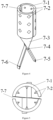
Figure 3 is a left view of the enveloping-type jaw; -
Figure 4 is a perspective view of the enveloping-type jaw; -
Figure 5 is a top view of the enveloping-type jaw; -
Figure 6 is a structural schematic diagram of crocodile jaw; -
Figure 7 is a left view ofFigure 6 . -
Figure 8 is a structural schematic diagram of the connecting tendon; -
Figure 9 is an internal structural schematic diagram of the connecting tendon; -
Figure 10 is a structural schematic diagram of a head-end enveloping-type clamping and conveying system. - In order to make the present application more obvious and easy to understand, the preferred embodiment and the accompanying drawings are described now in detail as follows.
- As shown in
Figure 1 andFigure 10 , the present application is a head-end enveloping-type clamping and conveying system, which comprises a jaw part and a pushing part, the pushing part comprises apush handle 1, apush steel cable 2, acore shaft 3, an adjustment wire, apull wire loader 5, and a connectingtendon 6; one end of thepush handle 1 is fixedly connected to one end of thepush steel cable 2, the outside of thepush steel cable 2 is provided with thepull wire loader 5 for pushing thepush steel cable 2 into a sheath, the interior of thepush handle 1 is connected to one end of thecore shaft 3, and the other end of thecore shaft 3 penetrates the interior of thepush steel cable 2 and is connected to the connectingtendon 6, and the connectingtendon 6 is connected to thejaw part 7 for clamping and releasing an occluder. The other end of thecore shaft 3 is connected to two connecting feet of the connectingtendon 6 through a first rotating shaft 6-6, the two connecting feet of the connectingtendon 6 are respectively connected to two connecting feet of thejaw part 7 for clamping and releasing the occluder through a second rotating shaft 6-8, the other end of thepush steel cable 2 is fixedly connected to one end of the connectingtendon 6, the other end of the connectingtendon 6 is connected to thejaw part 7 through a third rotating shaft 6-7. The adjustment wire provided on the outside of thepush steel cable 2 is provided in thepull wire loader 5. When the adjustment wire is in use, the adjustment wire cooperates with thejaw part 7 to adjust the position of thedegradable occluder 8 or retract thedegradable occluder 8 according to the requirements; one end of the adjustment wire connected to thedegradable occluder 8 is loosed to separate the adjustment wire from thedegradable occluder 8. Two ends of the adjustment wire are theother end 9 of the adjustment wire and oneend 4 of the adjustment wire respectively, theother end 9 of the adjustment wire is fixed on thepush handle 1; when thepush steel cable 2 is provided in the sheath through thepull wire loader 5, oneend 4 of the adjustment wire enters the sheath through thepull wire loader 5 and is connected to thedegradable occluder 8 through thejaw part 7, and then oneend 4 of the adjustment wire passes through thejaw part 7, the sheath, and thepull wire loader 5 in sequence, and returns to thepush handle 1. - As shown in
Figures 8 and9 , the connectingtendon 6 comprises a connecting tendon body 6-5, a fifth connecting foot 6-2, and a sixth connecting foot 6-3; a central hole for thecore shaft 3 to pass through is provided in the connecting tendon body 6-5, both sides of the connecting tendon body 6-5 are respectively provided with a long hole 6-4 which communicates with the central hole, one end of each of the fifth connecting foot 6-2 and the sixth connecting foot 6-3 are respectively arranged on both sides of the connecting tendon body 6-5, and are connected to the two connecting feet of thejaw part 7 through the second rotating shaft 6-8, one end of each of the fifth connecting foot 6-2 and the sixth connecting foot 6-3 respectively pass through the long holes 6-4 on both sides of the connecting tendon body 6-5, and are connected to the other end of thecore shaft 3 in the center hole of the connecting tendon body 6-5 through the first rotating shaft 6-6, the other end of the connectingtendon 6 is provided with a third shaft hole 6-1, the third shaft hole 6-1 of the connectingtendon 6 is connected to thejaw part 7 through the third rotating shaft 6-7. - The connecting
tendon 6 cooperates with thejaw part 7 to realize long-distance transmission movement, wherein the third rotating shaft 6-7 passes through the third shaft hole 6-1 and the shaft hole on thejaw part 7, so that the two are connected as a whole. The fifth connecting foot 6-2 and the sixth connecting foot 6-3 are connected with the two connecting feet of thejaw part 7, and the ends of the fifth connecting foot 6-2 and the sixth connecting foot 6-3 are connected with thecore shaft 3 and thepush handle 1, so as to control their movement at the far end. In order to realize long-distance transmission, the end of thepush handle 1 can control their movement. - When in use, the
push handle 1 is connected to thepush steel cable 2. Thepush steel cable 2 can be pushed into the sheath through thepull wire loader 5. Two ends of the adjustment wire are theother end 9 of the adjustment wire and oneend 4 of the adjustment wire respectively, theother end 9 of the adjustment wire is fixed on thepush handle 1; oneend 4 of the adjustment wire enters the sheath through thepull wire loader 5 and is connected to thedegradable occluder 8 through thejaw part 7, and then passes through thejaw part 7, the sheath, and thepull wire loader 5 in sequence, and returns to thepush handle 1, that is, oneend 4 of the adjustment wire is wrapped around for one circle and then returns to the initial position. Wherein, the adjustment wire only passes through one side of thedegradable occlude 8 and penetrates on the other side, so that the adjustment wire can pull thedegradable occluder 8 to move together, and the adjustment wire is not fixed with thedegradable occluder 8. Thepush handle 1 is internally connected to thecore shaft 3, which penetrates the interior of the wholepush steel cable 2 and is connected to the connectingtendon 6 to control the movement of thejaw part 7, so as to clamp and release the occluder. - The
core shaft 3 inside thepush steel cable 2 is made of special ductile material, which can realize good linkage and radial rotation for long-distance transmission. Thecore shaft 3 is connected to thejaw part 7 through the connectingtendon 6, which can realize long-distance locking and release. The adjustment wire is made of special materials, which is very thin and has high strength. It is located outside thepush steel cable 2 and can be withdrawn after the treatment; The adjustment wire cooperates with thejaw part 7 to be capable to adjust the position of thedegradable occluder 8 according to the requirements during the treatment, which can overcome the disadvantage of being capable to be conveyed only but not being capable to be adjusted in the past, and can retract thedegradable occluder 8 in case of emergency, greatly reducing the risk. It can better deal with various problems that may appear in the treatment, and make the treatment process more safe and controllable. - As shown in
Figure 2 , thepush handle 1 comprises a wristband 1-4, a pushing head 1-3, a pushing tendon 1-2, a turnbuckle 1-5, a connecting rod 1-7, and a push-pull block 1-6. One end of the wristband 1-4 is connected to one end of the connecting rod 1-7, the other end of the connecting rod 1-7 is provided with an open threaded head 1-1, the middle of the connecting rod 1-7 is provided with an open groove, a push-pull block 1-6 that is capable to slide on the connecting rod 1-7 is sleeved on the connecting rod 1-7, one end of thecore shaft 3 is fixedly connected to the pushing head 1-3 through the open threaded head 1-1, the pushing head 1-3 is fixed on the pushing tendon 1-2, the pushing tendon 1-2 is provided in the open groove, the outside of the pushing tendon 1-2 is connected to the push-pull block 1-6 sleeved on the connecting rod 1-7, the outside of the open threaded head 1-1 is sleeved with a turnbuckle 1-5 that makes the open threaded head 1-1 clamp thecore shaft 3, one end of thepush steel cable 2 is connected to the open threaded head 1-1. - The pushing head 1-3 is connected to the
core shaft 3 through the pushing tendon 1-2, which can control the forward and backward movement of thecore shaft 3, so as to remotely control the opening and closing of thejaw part 7. The turnbuckle 1-5 can be remotely locked after thejaw part 7 is closed, so as to firmly fix the occluder on thejaw part 7 of the conveying device. Wristband 1-4 are used to facilitate hand-held push and pull during operation, so as to realize its movement. - As shown in
Figures 3 and5 , thejaw part 7 is an enveloping-type jaw structure comprising 18 rivets 7-2 in total located on the inner wall of the semi-cylindrical jaw 7-1, which plays a fixed anti-skid role and can limit the left, right and up, down movement of thedegradable occluder 8 during use. The two semi-cylindrical jaws 7-1 combine to form an enveloping uniform-teeth jaw, the inner wall of the enveloping uniform-teeth jaw is cylindrical that is capable to cooperate well with a fusion ball of thedegradable occluder 8. The enveloping-type structure has large contact area and is not easy to pinch and damage the product; the integral connector 7-3 is the integral transition part that connects the first connecting foot 7-5, the second connecting foot 7-6 and the semi-cylindrical jaw 7-1, a first shaft hole 7-4 is provided at the connection between the integral connector 7-3 and the connecting foot, the third rotating shaft 6-7 is connected to the other end of the connecting tendon 6 through the first shaft hole 7-4 on the two integral connectors 7-3, so that the jaw can open and close; a reserved gap 7-7 is provided between the two semi-cylindrical jaws 7-1, so that the jaw can clamp the product (fusion ball) and can adapt to the specifications and models of products (fusion ball) in a certain size range, that is it can cooperate with a plurality of fusion balls of similar specifications; moreover, the degradable polymer material has certain elasticity, and the inner wall of the enveloping uniform-teeth jaw uses four-pyramid short-barb structure which can just make the polymer material slightly concave without damage, increase the friction, and make the degradable occluder 8 more firm in the conveying process and not easy to shift and pull off. The first connecting foot 7-5 and the second connecting foot 7-6 connected to the third rotating shaft 6-7 are connected to the connecting foot of the connectingtendon 6, which can carry out long-distance transmission movement through thepush handle 1. - In this embodiment, as shown in
Figures 6 and 7 , thejaw part 7 is an alligator tooth jaw structure, the two jaws form an alligator tooth jaw, the alligator tooth jaw is composed of two curved walls 7-10 and crocodile teeth 7-8 on the curved wall 7-10, the head end of the alligator tooth jaw is a top hole 7-9 with a circular opening, and the top hole 7-9 transitions smoothly with the curved wall 7-10, which make it not easily scratch the fusion ball, and can transition smoothly with the increase of force to make the clamping tighter, and has a certain margin, which can adapt to a plurality of fusion balls of similar specifications. Crocodile teeth 7-8 surround both sides of the top hole 7-9, the curved wall 7-10 plays the role of fixing the tail end of the fusion ball (there is a boss at the connection between the tail end and the net). The top hole 7-9 can clamp the tail part of the fusion ball in the hole, and the crocodile teeth 7-8 act on the tail end of the fusion ball to fix and prevent displacement. The third rotating shaft 6-7 passes through the second shaft hole 7-11 in the middle of the two jaw bars and is connected to the other end of the connectingtendon 6, the opening and closing movement is realized by the rotation of the third rotating shaft 6-7. The third connecting foot 7-12 and the fourth connecting foot 7-13 are connected to the connecting foot of the connectingtendon 6 of the conveying device, and can carry out long-distance transmission movement through thepush handle 1. Crocodile teeth 7-8 are at the head end, which can firmly fix the tail part of the fusion ball (the connecting part with the occluder network), and can be locked left and right to prevent product displacement, making it more firm in the conveying process and not easy to shift and pull off.
Claims (6)
- A head-end enveloping-type clamping and conveying system, comprising a jaw part (7) and a pushing part,wherein the pushing part comprises a push handle (1), a push steel cable (2), a core shaft (3), an adjustment wire, a pull wire loader (5), and a connecting tendon (6);one end of the push handle (1) is fixedly connected to one end of the push steel cable (2), the outside of the push steel cable (2) is provided with the pull wire loader (5) suitable for pushing the push steel cable (2) into a sheath, the interior of the push handle (1) is connected to one end of the core shaft (3), and the other end of the core shaft (3) penetrates the interior of the push steel cable (2) and is connected to the connecting tendon (6), and the connecting tendon (6) is connected to the jaw part (7) suitable for clamping and releasing an degradable occluder (8), characterized in that, the jaw part (7) comprises two jaw bars, the middle positions of the two jaw bars are movably connected through a third rotating shaft (6-7), one end of each of the two jaw bars are provided with a connecting foot respectively, two connecting feet of one end of each of the two jaw bars are flexibly connected to dlw two connecting feet of the connecting tendons (6) through a further rotating shaft (6-8), the other end of each of the two jaw bars are provided with a jaw respectively; when the two connecting feet of one end of each of the two jaw bars rotate relative to each other around the third rotating shaft (6-7), the two jaws of the other end of each of the two jaw bars also rotate relative to each other, thereby clamping the degradable occluder (8); when the two connecting feet of one end of each of the two jaw bars rotate opposite to each other around the third rotating shaft (6-7), the two jaw bars of the other end of each of the two jaw bars also rotate opposite to each other, thereby releasing the degradable occluder (8), wherein, the jaw part (7) is an enveloping-type jaw structure, the two jaws are two semi-cylindrical jaws (7-1) combined to form an enveloping uniform-teeth jaw, the inner wall of the enveloping uniform-teeth jaw is a cylindrical structure that is capable to cooperate with a fusion ball of the degradable occluder (8), a plurality of rivets (7-2) for preventing the degradable occluder (8) from moving left and right or up and down are evenly distributed on the inner wall of each semi-cylindrical jaw (7-1); the jaw bar comprise the semi-cylindrical jaw (7-1), an integral connector (7-3), and the connecting foot, the integral connector (7-3) is the integral transition part that connects the connecting foot and the semi-cylindrical jaw (7-1) on the jaw bars, a first shaft hole (7-4) is provided at the connection between the integral connector (7-3) and the connecting foot on the jaw bar, the rotating shaft (6-7) is connected to the other end of the connecting tendon (6) through the first shaft hole (7-4) on the two integral connectors (7-3); a reserved gap (7-7) is provided between the two semi-cylindrical jaws (7-1); orthe jaw part (7) is a crocodile-tooth jaw structure, two jaws form crocodile-tooth jaws, the crocodile-tooth jaws consist of two curved walls (7-10) and crocodile teeth (7-8) on the curved walls (7-10), the head-end of the crocodile-tooth jaws is a top hole (7-9) with circular opening, the top hole (7-9) smoothly transitions to the curved wall (7-10), the crocodile teeth (7-8) surround both sides of the top hole (7-9), the middle positions of the two jaw bars are provided with a second shaft hole (7-11), the rotating shaft (6-7) is connected to the other end of the connecting tendon (6) through the second shaft hole (7-11) in the middle of the two jaw bars.
- The head-end enveloping-type clamping and conveying system according to claim 1, wherein the other end of the core shaft (3) is connected to the two connecting feet of the connecting tendon (6) through a yet another rotating shaft (6-6), the other end of the push steel cable (2) is fixedly connected to one end of the connecting tendon (6), the other end of the connecting tendon (6) is connected to the jaw part (7) through the third rotating shaft (6-7)
- The head-end enveloping-type clamping and conveying system according to claim 1 or 2, wherein the adjustment wire provided on the outside of the push steel cable (2) is provided in the pull wire loader (5).
- The head-end enveloping-type clamping and conveying system according to claim 3, wherein two ends of the adjustment wire are another end (9) of the adjustment wire and one end (4) of the adjustment wire respectively, the other end (9) of the adjustment wire is fixed on the push handle (1); when the push steel cable (2) is provided in the sheath through the pull wire loader (5), one end (4) of the adjustment wire enters the sheath through the pull wire loader (5) and is connected to the degradable occluder (8) through the jaw part (7), and the one end (4) of the adjustment wire passes through the jaw part (7), the sheath, and the pull wire loader (5) in sequence, and returns to the push handle (1).
- The head-end enveloping-type clamping and conveying system according to claim 2, wherein the connecting tendon (6) comprises a connecting tendon body (6-5), a fifth connecting foot (6-2), and a sixth connecting foot (6-3); wherein a central hole for the core shaft (3)to pass through is provided in the connecting tendon body (6-5), both sides of the connecting tendon body (6-5) are respectively provided with a long hole (6-4) which communicates with the central hole, one end of each of the fifth connecting foot (6-2) and the sixth connecting foot (6-3) are respectively arranged on both sides of the connecting tendon body (6-5), and are connected to the two connecting feet of the jaw part (7) through the further rotating shaft (6-8), one end of each of the fifth connecting foot (6-2) and the sixth connecting foot (6-3) respectively pass through the long holes (6-4) on both sides of the connecting tendon body (6-5), and are connected to the other end of the core shaft (3) in the center hole of the connecting tendon body (6-5) through the yet another rotating shaft (6-6), the other end of the connecting tendon (6) is provided with a third shaft hole (6-1), the third shaft hole (6-1) of the connecting tendon (6) is connected to the jaw part (7) through the rotating shaft (6-7).
- The head-end enveloping-type clamping and conveying system according to claim 1, wherein the push handle (1) comprises a wristband (1-4), a pushing head (1-3), a pushing tendon (1-2), a turnbuckle (1-5), a connecting rod (1-7), and a push-pull block (1-6); wherein one end of the wristband (1-4) is connected to one end of the connecting rod (1-7), an opposite end of the connecting rod (1-7) is provided with an open threaded head (1-1), the middle of the connecting rod (1-7) is provided with an open groove, a push-pull block (1-6) that is capable to slide on the connecting rod (1-7) is sleeved on the connecting rod (1-7), one end of the core shaft (3) is fixedly connected to the pushing head (1-3) through the open threaded head (1-1), the pushing head (1-3) is fixed on the pushing tendon (1-2), the pushing tendon (1-2) is provided in the open groove, the outside of the pushing tendon (1-2) is connected to the push-pull block (1-6) sleeved on the connecting rod (1-7), the outside of the open threaded head (1-1) is sleeved with the turnbuckle (1-5) that makes the open threaded head (1-1) clamp the core shaft (3), one end of the push steel cable (2) is connected to the open threaded head (1-1).
Applications Claiming Priority (2)
| Application Number | Priority Date | Filing Date | Title |
|---|---|---|---|
| CN202010546781.XA CN111658026B (en) | 2020-06-16 | 2020-06-16 | Head end encircling type clamping conveying system |
| PCT/CN2021/089249 WO2021253980A1 (en) | 2020-06-16 | 2021-04-23 | Head end enveloping-type clamping and conveying system |
Publications (3)
| Publication Number | Publication Date |
|---|---|
| EP4005501A1 EP4005501A1 (en) | 2022-06-01 |
| EP4005501A4 EP4005501A4 (en) | 2022-11-16 |
| EP4005501B1 true EP4005501B1 (en) | 2024-01-24 |
Family
ID=72387831
Family Applications (1)
| Application Number | Title | Priority Date | Filing Date |
|---|---|---|---|
| EP21825366.4A Active EP4005501B1 (en) | 2020-06-16 | 2021-04-23 | Head end enveloping-type clamping and conveying system |
Country Status (5)
| Country | Link |
|---|---|
| EP (1) | EP4005501B1 (en) |
| CN (1) | CN111658026B (en) |
| ES (1) | ES2979309T3 (en) |
| PL (1) | PL4005501T3 (en) |
| WO (1) | WO2021253980A1 (en) |
Families Citing this family (3)
| Publication number | Priority date | Publication date | Assignee | Title |
|---|---|---|---|---|
| CN111658026B (en) * | 2020-06-16 | 2024-11-29 | 上海形状记忆合金材料有限公司 | Head end encircling type clamping conveying system |
| CN113413243B (en) * | 2021-06-22 | 2025-12-09 | 上海形状记忆合金材料有限公司 | Lockable rivetless biological atrial shunt device |
| CN114027915B (en) * | 2021-08-26 | 2023-09-08 | 上海形状记忆合金材料有限公司 | Cardiovascular plugging device conveying device with molding line protection |
Family Cites Families (12)
| Publication number | Priority date | Publication date | Assignee | Title |
|---|---|---|---|---|
| DE29500381U1 (en) * | 1994-08-24 | 1995-07-20 | Schneidt, Bernhard, Ing.(grad.), 63571 Gelnhausen | Device for closing a duct, in particular the ductus arteriosus |
| US7955354B2 (en) * | 2005-11-14 | 2011-06-07 | Occlutech Gmbh | Occlusion device and surgical instrument and method for its implantation/explantation |
| EP2609872B2 (en) * | 2009-05-06 | 2019-01-02 | Occlutech Holding AG | Medical device for a delivery of a medical implant |
| US8956389B2 (en) * | 2009-06-22 | 2015-02-17 | W. L. Gore & Associates, Inc. | Sealing device and delivery system |
| CN201578327U (en) * | 2009-12-30 | 2010-09-15 | 杭州康基医疗器械有限公司 | Direct-view minimally invasive nondestructive small grasping forceps |
| CN201905938U (en) * | 2010-11-30 | 2011-07-27 | 上海长海医院 | Conveying and recovery device for transcatheter minimally invasive intervention operation |
| CN103690202B (en) * | 2013-12-30 | 2016-04-20 | 先健科技(深圳)有限公司 | The conveyer device of implant and implanted medical device |
| CN106618664B (en) * | 2016-12-06 | 2023-04-14 | 上海心玮医疗科技股份有限公司 | Left auricle occluder conveying system |
| CN109498074A (en) * | 2019-01-04 | 2019-03-22 | 上海形状记忆合金材料有限公司 | Method Wholly-degradable plugging device dedicated driving means and its connect with plugging device |
| CN110876633B (en) * | 2019-12-03 | 2024-06-14 | 江苏博朗森思医疗器械有限公司 | Special conveyer of degradable plugging device |
| CN111658026B (en) * | 2020-06-16 | 2024-11-29 | 上海形状记忆合金材料有限公司 | Head end encircling type clamping conveying system |
| CN212939808U (en) * | 2020-06-16 | 2021-04-13 | 上海形状记忆合金材料有限公司 | A head-end embracing clamping conveying system |
-
2020
- 2020-06-16 CN CN202010546781.XA patent/CN111658026B/en active Active
-
2021
- 2021-04-23 PL PL21825366.4T patent/PL4005501T3/en unknown
- 2021-04-23 WO PCT/CN2021/089249 patent/WO2021253980A1/en not_active Ceased
- 2021-04-23 ES ES21825366T patent/ES2979309T3/en active Active
- 2021-04-23 EP EP21825366.4A patent/EP4005501B1/en active Active
Also Published As
| Publication number | Publication date |
|---|---|
| EP4005501A1 (en) | 2022-06-01 |
| CN111658026A (en) | 2020-09-15 |
| CN111658026B (en) | 2024-11-29 |
| WO2021253980A1 (en) | 2021-12-23 |
| ES2979309T3 (en) | 2024-09-25 |
| PL4005501T3 (en) | 2024-06-10 |
| EP4005501A4 (en) | 2022-11-16 |
Similar Documents
| Publication | Publication Date | Title |
|---|---|---|
| US20230108042A1 (en) | Hemostatic clipping devices and methods | |
| EP4005501A1 (en) | Head end enveloping-type clamping and conveying system | |
| CN102727276B (en) | A tissue hemostatic clamping device | |
| CN207871026U (en) | A kind of recyclable transport system of intervention heart valve of stable operation | |
| CN109953779B (en) | Clamping device and system for securing tissue | |
| EP3247443B1 (en) | Guide catheter with steering mechanisms | |
| EP2630919B1 (en) | Intravascular delivery device, system and implant | |
| WO2007054014A1 (en) | Delivery device for delivering a self-expanding stent | |
| CN212939808U (en) | A head-end embracing clamping conveying system | |
| US11844911B2 (en) | Vascular access disassembling needle device and method | |
| EP3903744B1 (en) | Delivery catheter and delivery device for artificial valve | |
| WO2013060832A1 (en) | Device combination for connecting hollow organs (anastomosis) | |
| US20210161694A1 (en) | Delivery device | |
| CN202699219U (en) | Tissue hemostasis clamping device | |
| CN114680992A (en) | Collet assembly and hemostatic clip for hemostatic clip | |
| CN110876633B (en) | Special conveyer of degradable plugging device | |
| CN109984778A (en) | Medical sutures device and sewing system | |
| CN215018331U (en) | Collet assembly and hemostatic clip for hemostatic clip | |
| CN217548112U (en) | Delivery system for atrial shunt | |
| CN219229967U (en) | An electronically controlled atrial shunt delivery system | |
| US20210322192A1 (en) | Medical Device Implantation Apparatus | |
| CN213310062U (en) | Rotary clamp device | |
| WO2021129631A1 (en) | Stent delivery and release device and stent delivery and release system | |
| CN114869360A (en) | Delivery system for atrial shunt | |
| CN120227200A (en) | A valve repair system with a clutch assembly |
Legal Events
| Date | Code | Title | Description |
|---|---|---|---|
| STAA | Information on the status of an ep patent application or granted ep patent |
Free format text: STATUS: THE INTERNATIONAL PUBLICATION HAS BEEN MADE |
|
| PUAI | Public reference made under article 153(3) epc to a published international application that has entered the european phase |
Free format text: ORIGINAL CODE: 0009012 |
|
| STAA | Information on the status of an ep patent application or granted ep patent |
Free format text: STATUS: REQUEST FOR EXAMINATION WAS MADE |
|
| 17P | Request for examination filed |
Effective date: 20220225 |
|
| AK | Designated contracting states |
Kind code of ref document: A1 Designated state(s): AL AT BE BG CH CY CZ DE DK EE ES FI FR GB GR HR HU IE IS IT LI LT LU LV MC MK MT NL NO PL PT RO RS SE SI SK SM TR |
|
| A4 | Supplementary search report drawn up and despatched |
Effective date: 20221019 |
|
| RIC1 | Information provided on ipc code assigned before grant |
Ipc: A61B 17/12 20060101ALN20221013BHEP Ipc: A61B 17/00 20060101AFI20221013BHEP |
|
| RIC1 | Information provided on ipc code assigned before grant |
Ipc: A61B 17/12 20060101ALN20230628BHEP Ipc: A61B 17/00 20060101AFI20230628BHEP |
|
| GRAP | Despatch of communication of intention to grant a patent |
Free format text: ORIGINAL CODE: EPIDOSNIGR1 |
|
| STAA | Information on the status of an ep patent application or granted ep patent |
Free format text: STATUS: GRANT OF PATENT IS INTENDED |
|
| RIC1 | Information provided on ipc code assigned before grant |
Ipc: A61B 17/12 20060101ALN20230720BHEP Ipc: A61B 17/00 20060101AFI20230720BHEP |
|
| DAV | Request for validation of the european patent (deleted) | ||
| DAX | Request for extension of the european patent (deleted) | ||
| INTG | Intention to grant announced |
Effective date: 20230808 |
|
| GRAS | Grant fee paid |
Free format text: ORIGINAL CODE: EPIDOSNIGR3 |
|
| GRAA | (expected) grant |
Free format text: ORIGINAL CODE: 0009210 |
|
| STAA | Information on the status of an ep patent application or granted ep patent |
Free format text: STATUS: THE PATENT HAS BEEN GRANTED |
|
| AK | Designated contracting states |
Kind code of ref document: B1 Designated state(s): AL AT BE BG CH CY CZ DE DK EE ES FI FR GB GR HR HU IE IS IT LI LT LU LV MC MK MT NL NO PL PT RO RS SE SI SK SM TR |
|
| REG | Reference to a national code |
Ref country code: GB Ref legal event code: FG4D |
|
| REG | Reference to a national code |
Ref country code: CH Ref legal event code: EP |
|
| REG | Reference to a national code |
Ref country code: IE Ref legal event code: FG4D |
|
| REG | Reference to a national code |
Ref country code: DE Ref legal event code: R096 Ref document number: 602021008798 Country of ref document: DE |
|
| REG | Reference to a national code |
Ref country code: NL Ref legal event code: FP |
|
| REG | Reference to a national code |
Ref country code: LT Ref legal event code: MG9D |
|
| PG25 | Lapsed in a contracting state [announced via postgrant information from national office to epo] |
Ref country code: IS Free format text: LAPSE BECAUSE OF FAILURE TO SUBMIT A TRANSLATION OF THE DESCRIPTION OR TO PAY THE FEE WITHIN THE PRESCRIBED TIME-LIMIT Effective date: 20240524 |
|
| PG25 | Lapsed in a contracting state [announced via postgrant information from national office to epo] |
Ref country code: LT Free format text: LAPSE BECAUSE OF FAILURE TO SUBMIT A TRANSLATION OF THE DESCRIPTION OR TO PAY THE FEE WITHIN THE PRESCRIBED TIME-LIMIT Effective date: 20240124 |
|
| PG25 | Lapsed in a contracting state [announced via postgrant information from national office to epo] |
Ref country code: GR Free format text: LAPSE BECAUSE OF FAILURE TO SUBMIT A TRANSLATION OF THE DESCRIPTION OR TO PAY THE FEE WITHIN THE PRESCRIBED TIME-LIMIT Effective date: 20240425 |
|
| REG | Reference to a national code |
Ref country code: AT Ref legal event code: MK05 Ref document number: 1651543 Country of ref document: AT Kind code of ref document: T Effective date: 20240124 |
|
| PG25 | Lapsed in a contracting state [announced via postgrant information from national office to epo] |
Ref country code: HR Free format text: LAPSE BECAUSE OF FAILURE TO SUBMIT A TRANSLATION OF THE DESCRIPTION OR TO PAY THE FEE WITHIN THE PRESCRIBED TIME-LIMIT Effective date: 20240124 Ref country code: RS Free format text: LAPSE BECAUSE OF FAILURE TO SUBMIT A TRANSLATION OF THE DESCRIPTION OR TO PAY THE FEE WITHIN THE PRESCRIBED TIME-LIMIT Effective date: 20240424 |
|
| PG25 | Lapsed in a contracting state [announced via postgrant information from national office to epo] |
Ref country code: AT Free format text: LAPSE BECAUSE OF FAILURE TO SUBMIT A TRANSLATION OF THE DESCRIPTION OR TO PAY THE FEE WITHIN THE PRESCRIBED TIME-LIMIT Effective date: 20240124 |
|
| PG25 | Lapsed in a contracting state [announced via postgrant information from national office to epo] |
Ref country code: RS Free format text: LAPSE BECAUSE OF FAILURE TO SUBMIT A TRANSLATION OF THE DESCRIPTION OR TO PAY THE FEE WITHIN THE PRESCRIBED TIME-LIMIT Effective date: 20240424 Ref country code: NO Free format text: LAPSE BECAUSE OF FAILURE TO SUBMIT A TRANSLATION OF THE DESCRIPTION OR TO PAY THE FEE WITHIN THE PRESCRIBED TIME-LIMIT Effective date: 20240424 Ref country code: LT Free format text: LAPSE BECAUSE OF FAILURE TO SUBMIT A TRANSLATION OF THE DESCRIPTION OR TO PAY THE FEE WITHIN THE PRESCRIBED TIME-LIMIT Effective date: 20240124 Ref country code: IS Free format text: LAPSE BECAUSE OF FAILURE TO SUBMIT A TRANSLATION OF THE DESCRIPTION OR TO PAY THE FEE WITHIN THE PRESCRIBED TIME-LIMIT Effective date: 20240524 Ref country code: HR Free format text: LAPSE BECAUSE OF FAILURE TO SUBMIT A TRANSLATION OF THE DESCRIPTION OR TO PAY THE FEE WITHIN THE PRESCRIBED TIME-LIMIT Effective date: 20240124 Ref country code: GR Free format text: LAPSE BECAUSE OF FAILURE TO SUBMIT A TRANSLATION OF THE DESCRIPTION OR TO PAY THE FEE WITHIN THE PRESCRIBED TIME-LIMIT Effective date: 20240425 Ref country code: FI Free format text: LAPSE BECAUSE OF FAILURE TO SUBMIT A TRANSLATION OF THE DESCRIPTION OR TO PAY THE FEE WITHIN THE PRESCRIBED TIME-LIMIT Effective date: 20240124 Ref country code: BG Free format text: LAPSE BECAUSE OF FAILURE TO SUBMIT A TRANSLATION OF THE DESCRIPTION OR TO PAY THE FEE WITHIN THE PRESCRIBED TIME-LIMIT Effective date: 20240124 Ref country code: AT Free format text: LAPSE BECAUSE OF FAILURE TO SUBMIT A TRANSLATION OF THE DESCRIPTION OR TO PAY THE FEE WITHIN THE PRESCRIBED TIME-LIMIT Effective date: 20240124 |
|
| PG25 | Lapsed in a contracting state [announced via postgrant information from national office to epo] |
Ref country code: PT Free format text: LAPSE BECAUSE OF FAILURE TO SUBMIT A TRANSLATION OF THE DESCRIPTION OR TO PAY THE FEE WITHIN THE PRESCRIBED TIME-LIMIT Effective date: 20240524 |
|
| PG25 | Lapsed in a contracting state [announced via postgrant information from national office to epo] |
Ref country code: SE Free format text: LAPSE BECAUSE OF FAILURE TO SUBMIT A TRANSLATION OF THE DESCRIPTION OR TO PAY THE FEE WITHIN THE PRESCRIBED TIME-LIMIT Effective date: 20240124 Ref country code: PT Free format text: LAPSE BECAUSE OF FAILURE TO SUBMIT A TRANSLATION OF THE DESCRIPTION OR TO PAY THE FEE WITHIN THE PRESCRIBED TIME-LIMIT Effective date: 20240524 Ref country code: LV Free format text: LAPSE BECAUSE OF FAILURE TO SUBMIT A TRANSLATION OF THE DESCRIPTION OR TO PAY THE FEE WITHIN THE PRESCRIBED TIME-LIMIT Effective date: 20240124 |
|
| REG | Reference to a national code |
Ref country code: ES Ref legal event code: FG2A Ref document number: 2979309 Country of ref document: ES Kind code of ref document: T3 Effective date: 20240925 |
|
| PG25 | Lapsed in a contracting state [announced via postgrant information from national office to epo] |
Ref country code: DK Free format text: LAPSE BECAUSE OF FAILURE TO SUBMIT A TRANSLATION OF THE DESCRIPTION OR TO PAY THE FEE WITHIN THE PRESCRIBED TIME-LIMIT Effective date: 20240124 |
|
| PG25 | Lapsed in a contracting state [announced via postgrant information from national office to epo] |
Ref country code: SM Free format text: LAPSE BECAUSE OF FAILURE TO SUBMIT A TRANSLATION OF THE DESCRIPTION OR TO PAY THE FEE WITHIN THE PRESCRIBED TIME-LIMIT Effective date: 20240124 |
|
| PG25 | Lapsed in a contracting state [announced via postgrant information from national office to epo] |
Ref country code: CZ Free format text: LAPSE BECAUSE OF FAILURE TO SUBMIT A TRANSLATION OF THE DESCRIPTION OR TO PAY THE FEE WITHIN THE PRESCRIBED TIME-LIMIT Effective date: 20240124 Ref country code: EE Free format text: LAPSE BECAUSE OF FAILURE TO SUBMIT A TRANSLATION OF THE DESCRIPTION OR TO PAY THE FEE WITHIN THE PRESCRIBED TIME-LIMIT Effective date: 20240124 |
|
| REG | Reference to a national code |
Ref country code: DE Ref legal event code: R097 Ref document number: 602021008798 Country of ref document: DE |
|
| PG25 | Lapsed in a contracting state [announced via postgrant information from national office to epo] |
Ref country code: SK Free format text: LAPSE BECAUSE OF FAILURE TO SUBMIT A TRANSLATION OF THE DESCRIPTION OR TO PAY THE FEE WITHIN THE PRESCRIBED TIME-LIMIT Effective date: 20240124 |
|
| PG25 | Lapsed in a contracting state [announced via postgrant information from national office to epo] |
Ref country code: SM Free format text: LAPSE BECAUSE OF FAILURE TO SUBMIT A TRANSLATION OF THE DESCRIPTION OR TO PAY THE FEE WITHIN THE PRESCRIBED TIME-LIMIT Effective date: 20240124 Ref country code: SK Free format text: LAPSE BECAUSE OF FAILURE TO SUBMIT A TRANSLATION OF THE DESCRIPTION OR TO PAY THE FEE WITHIN THE PRESCRIBED TIME-LIMIT Effective date: 20240124 Ref country code: EE Free format text: LAPSE BECAUSE OF FAILURE TO SUBMIT A TRANSLATION OF THE DESCRIPTION OR TO PAY THE FEE WITHIN THE PRESCRIBED TIME-LIMIT Effective date: 20240124 Ref country code: DK Free format text: LAPSE BECAUSE OF FAILURE TO SUBMIT A TRANSLATION OF THE DESCRIPTION OR TO PAY THE FEE WITHIN THE PRESCRIBED TIME-LIMIT Effective date: 20240124 Ref country code: CZ Free format text: LAPSE BECAUSE OF FAILURE TO SUBMIT A TRANSLATION OF THE DESCRIPTION OR TO PAY THE FEE WITHIN THE PRESCRIBED TIME-LIMIT Effective date: 20240124 |
|
| PG25 | Lapsed in a contracting state [announced via postgrant information from national office to epo] |
Ref country code: MC Free format text: LAPSE BECAUSE OF FAILURE TO SUBMIT A TRANSLATION OF THE DESCRIPTION OR TO PAY THE FEE WITHIN THE PRESCRIBED TIME-LIMIT Effective date: 20240124 |
|
| PG25 | Lapsed in a contracting state [announced via postgrant information from national office to epo] |
Ref country code: MC Free format text: LAPSE BECAUSE OF FAILURE TO SUBMIT A TRANSLATION OF THE DESCRIPTION OR TO PAY THE FEE WITHIN THE PRESCRIBED TIME-LIMIT Effective date: 20240124 |
|
| PLBE | No opposition filed within time limit |
Free format text: ORIGINAL CODE: 0009261 |
|
| STAA | Information on the status of an ep patent application or granted ep patent |
Free format text: STATUS: NO OPPOSITION FILED WITHIN TIME LIMIT |
|
| PG25 | Lapsed in a contracting state [announced via postgrant information from national office to epo] |
Ref country code: LU Free format text: LAPSE BECAUSE OF NON-PAYMENT OF DUE FEES Effective date: 20240423 |
|
| REG | Reference to a national code |
Ref country code: BE Ref legal event code: MM Effective date: 20240430 |
|
| PG25 | Lapsed in a contracting state [announced via postgrant information from national office to epo] |
Ref country code: LU Free format text: LAPSE BECAUSE OF NON-PAYMENT OF DUE FEES Effective date: 20240423 |
|
| 26N | No opposition filed |
Effective date: 20241025 |
|
| PG25 | Lapsed in a contracting state [announced via postgrant information from national office to epo] |
Ref country code: BE Free format text: LAPSE BECAUSE OF NON-PAYMENT OF DUE FEES Effective date: 20240430 |
|
| PG25 | Lapsed in a contracting state [announced via postgrant information from national office to epo] |
Ref country code: BE Free format text: LAPSE BECAUSE OF NON-PAYMENT OF DUE FEES Effective date: 20240430 |
|
| PGFP | Annual fee paid to national office [announced via postgrant information from national office to epo] |
Ref country code: NL Payment date: 20250325 Year of fee payment: 5 |
|
| PGFP | Annual fee paid to national office [announced via postgrant information from national office to epo] |
Ref country code: IE Payment date: 20250320 Year of fee payment: 5 |
|
| PG25 | Lapsed in a contracting state [announced via postgrant information from national office to epo] |
Ref country code: SI Free format text: LAPSE BECAUSE OF FAILURE TO SUBMIT A TRANSLATION OF THE DESCRIPTION OR TO PAY THE FEE WITHIN THE PRESCRIBED TIME-LIMIT Effective date: 20240124 |
|
| PGFP | Annual fee paid to national office [announced via postgrant information from national office to epo] |
Ref country code: PL Payment date: 20250319 Year of fee payment: 5 |
|
| PGFP | Annual fee paid to national office [announced via postgrant information from national office to epo] |
Ref country code: DE Payment date: 20250411 Year of fee payment: 5 |
|
| PGFP | Annual fee paid to national office [announced via postgrant information from national office to epo] |
Ref country code: GB Payment date: 20250417 Year of fee payment: 5 Ref country code: ES Payment date: 20250512 Year of fee payment: 5 |
|
| PGFP | Annual fee paid to national office [announced via postgrant information from national office to epo] |
Ref country code: IT Payment date: 20250409 Year of fee payment: 5 |
|
| PGFP | Annual fee paid to national office [announced via postgrant information from national office to epo] |
Ref country code: FR Payment date: 20250429 Year of fee payment: 5 |
|
| PGFP | Annual fee paid to national office [announced via postgrant information from national office to epo] |
Ref country code: CH Payment date: 20250501 Year of fee payment: 5 |
|
| PGFP | Annual fee paid to national office [announced via postgrant information from national office to epo] |
Ref country code: TR Payment date: 20250409 Year of fee payment: 5 |
|
| PG25 | Lapsed in a contracting state [announced via postgrant information from national office to epo] |
Ref country code: CY Free format text: LAPSE BECAUSE OF FAILURE TO SUBMIT A TRANSLATION OF THE DESCRIPTION OR TO PAY THE FEE WITHIN THE PRESCRIBED TIME-LIMIT; INVALID AB INITIO Effective date: 20210423 |
|
| PG25 | Lapsed in a contracting state [announced via postgrant information from national office to epo] |
Ref country code: RO Free format text: LAPSE BECAUSE OF FAILURE TO SUBMIT A TRANSLATION OF THE DESCRIPTION OR TO PAY THE FEE WITHIN THE PRESCRIBED TIME-LIMIT Effective date: 20240124 |
|
| PG25 | Lapsed in a contracting state [announced via postgrant information from national office to epo] |
Ref country code: HU Free format text: LAPSE BECAUSE OF FAILURE TO SUBMIT A TRANSLATION OF THE DESCRIPTION OR TO PAY THE FEE WITHIN THE PRESCRIBED TIME-LIMIT; INVALID AB INITIO Effective date: 20210423 |