EP4005486A1 - Ct system and method and device controlling the position of the x-ray tube thereof - Google Patents
Ct system and method and device controlling the position of the x-ray tube thereof Download PDFInfo
- Publication number
- EP4005486A1 EP4005486A1 EP21210214.9A EP21210214A EP4005486A1 EP 4005486 A1 EP4005486 A1 EP 4005486A1 EP 21210214 A EP21210214 A EP 21210214A EP 4005486 A1 EP4005486 A1 EP 4005486A1
- Authority
- EP
- European Patent Office
- Prior art keywords
- signal
- encoder data
- ray tube
- sensor
- data containing
- Prior art date
- Legal status (The legal status is an assumption and is not a legal conclusion. Google has not performed a legal analysis and makes no representation as to the accuracy of the status listed.)
- Granted
Links
Images

Classifications
-
- A—HUMAN NECESSITIES
- A61—MEDICAL OR VETERINARY SCIENCE; HYGIENE
- A61B—DIAGNOSIS; SURGERY; IDENTIFICATION
- A61B6/00—Apparatus or devices for radiation diagnosis; Apparatus or devices for radiation diagnosis combined with radiation therapy equipment
- A61B6/44—Constructional features of apparatus for radiation diagnosis
- A61B6/4476—Constructional features of apparatus for radiation diagnosis related to motor-assisted motion of the source unit
-
- A—HUMAN NECESSITIES
- A61—MEDICAL OR VETERINARY SCIENCE; HYGIENE
- A61B—DIAGNOSIS; SURGERY; IDENTIFICATION
- A61B6/00—Apparatus or devices for radiation diagnosis; Apparatus or devices for radiation diagnosis combined with radiation therapy equipment
- A61B6/02—Arrangements for diagnosis sequentially in different planes; Stereoscopic radiation diagnosis
- A61B6/03—Computed tomography [CT]
- A61B6/032—Transmission computed tomography [CT]
-
- A—HUMAN NECESSITIES
- A61—MEDICAL OR VETERINARY SCIENCE; HYGIENE
- A61B—DIAGNOSIS; SURGERY; IDENTIFICATION
- A61B6/00—Apparatus or devices for radiation diagnosis; Apparatus or devices for radiation diagnosis combined with radiation therapy equipment
- A61B6/44—Constructional features of apparatus for radiation diagnosis
- A61B6/4429—Constructional features of apparatus for radiation diagnosis related to the mounting of source units and detector units
- A61B6/4435—Constructional features of apparatus for radiation diagnosis related to the mounting of source units and detector units the source unit and the detector unit being coupled by a rigid structure
-
- A—HUMAN NECESSITIES
- A61—MEDICAL OR VETERINARY SCIENCE; HYGIENE
- A61B—DIAGNOSIS; SURGERY; IDENTIFICATION
- A61B6/00—Apparatus or devices for radiation diagnosis; Apparatus or devices for radiation diagnosis combined with radiation therapy equipment
- A61B6/54—Control of apparatus or devices for radiation diagnosis
- A61B6/547—Control of apparatus or devices for radiation diagnosis involving tracking of position of the device or parts of the device
-
- A—HUMAN NECESSITIES
- A61—MEDICAL OR VETERINARY SCIENCE; HYGIENE
- A61B—DIAGNOSIS; SURGERY; IDENTIFICATION
- A61B6/00—Apparatus or devices for radiation diagnosis; Apparatus or devices for radiation diagnosis combined with radiation therapy equipment
- A61B6/58—Testing, adjusting or calibrating thereof
- A61B6/582—Calibration
-
- A—HUMAN NECESSITIES
- A61—MEDICAL OR VETERINARY SCIENCE; HYGIENE
- A61B—DIAGNOSIS; SURGERY; IDENTIFICATION
- A61B6/00—Apparatus or devices for radiation diagnosis; Apparatus or devices for radiation diagnosis combined with radiation therapy equipment
- A61B6/58—Testing, adjusting or calibrating thereof
- A61B6/582—Calibration
- A61B6/585—Calibration of detector units
Definitions
- the disclosure relates to the technical field of medical devices, in particular to a method and a device of controlling the position of the X-ray tube in a computed tomography (CT) system, and a CT system.
- CT computed tomography
- a CT system mainly comprises an X-ray tube, an X-ray detector array, a gantry and a patient bed.
- the X-ray tube and the X-ray detector array are disposed on the gantry rotating around the patient bed.
- the patient bed can move relative to the gantry.
- the X-ray tube generates a sector X-ray beam, and the X-ray beam passes one slice of an object (for example, a patient) which is being imaged and irradiates on the X-ray detector array.
- the included angle between the X-ray beam and the body slice of the patient and the position of the patient bed relative to the gantry change continuously.
- the angular position (AP) of the X-ray tube is a very important parameter of the CT system and affects the imaging quality of the CT system. Especially, if the patient needs to use CT for X-ray interventional therapy, it is necessary to precisely position the X-ray tube.
- a high-cost AP measurement system and a motor are adopted for a high-end CT system (for example, Definition system).
- a DC motor which can precisely position a sensor is used to acquire the precise position of the X-ray tube in a high-end CT system, it will take a lot of time and cost because the bearing needs to be assembled by use of DC driving.
- the minimum step of the position of the X-ray is 15 degrees and the accuracy is 2 degrees because of the limited number of check points in a low-end CT system. It is difficult to apply the interventional therapy in a low-end CT system because the low-end CT system cannot guarantee that the X-ray tube stops, with a step of 1 degree.
- a method of controlling the position of the X-ray tube of a CT system comprises: acquiring an AP signal output by an AP sensor of the CT system, an IP signal output by an IP sensor and encoder data output by a motor, determining a homing positioning signal APo of the AP signal based on the AP signal and the IP signal, wherein the homing positioning signal APo is used to determine the starting point of the period of rotation of the X-ray tube, utilizing the encoder data to calculate the encoder data containing AP signal based on the determined homing positioning signal AP 0 , wherein the encoder data containing AP signal is the AP signal calibrated by use of the encoder data, and controlling the position of the X-ray tube based on the encoder data containing AP signal.
- the AP signal is an angular position signal acquired after the AP sensor detects a plurality of check points arranged at even intervals on the outer circumferential surface of the gantry of the CT system
- the IP signal is an IP signal acquired after the IP sensor detects a reference check point arranged on the outer circumferential surface of the gantry of the CT system
- the IP signal is used to determine the period of rotation of the X-ray tube
- the encoder data is data output by the encoder of the motor and is used to control the speed of rotation of the X-ray tube.
- determining a homing positioning signal AP 0 of the AP signal based on the AP signal and the IP signal comprises: detecting whether the current IP signal is a high-level signal, and determining the high-level signal of the AP signal in the period in which the current IP signal is continuously a high-level signal to be the homing positioning signal AP 0 if the current IP signal is a high-level signal.
- the step positioning precision of the X-ray tube is increased to 1 degree, without any new component added.
- utilizing the encoder data to calculate the encoder data containing AP signal based on the determined homing positioning signal APo comprises: detecting each high-level signal AP i of the AP signal in the period from the homing positioning signal APo to when the IP signal is a high-level signal again, respectively calculating the pulse count of the encoder data in the time segment between the homing positioning signal APo and each high-level signal APi, and saving the correspondence between the calculated pulse count of the encoder data and the AP signal as an encoder data containing AP signal.
- the correspondence between an AP signal and encoder data can more precisely be calculated, and thus making it possible to precisely position the X-ray tube.
- controlling the position of the X-ray tube based on the encoder data containing AP signal comprises: reading the saved encoder data containing AP signal during the rotation of the gantry of the CT system, and utilizing the encoder data containing AP signal to calibrate the position of the X-ray tube so as to control the position of the X-ray tube.
- the position of the X-ray tube is calibrated by use of the pre-adjustment mode during the subsequent operation, and thus the precision of positioning the X-ray tube is improved.
- a device of controlling the position of the X-ray tube of a CT system comprises: an acquisition module, configured to acquire an AP signal output by an AP sensor of the CT system, an IP signal output by an IP sensor and encoder data output by a motor, a determination module, configured to determine a homing positioning signal APo of the AP signal based on the AP signal and the IP signal, wherein the homing positioning signal APo is used to determine the starting point of the period of rotation of the X-ray tube, a calculation module, configured to utilize the encoder data to calculate the encoder data containing AP signal based on the determined homing positioning signal AP 0 , wherein the encoder data containing AP signal is the AP signal calibrated by use of the encoder data, and a control module, configured to control the position of the X-ray tube based on the encoder data containing AP signal.
- the determination module is further configured to detect whether the current IP signal is a high-level signal, and determine the high-level signal of the AP signal in the period in which the current IP signal is continuously a high-level signal to be the homing positioning signal AP 0 if the current IP signal is a high-level signal.
- the step positioning precision of the X-ray tube is increased to 1 degree, without any new component added.
- the calculation module is further configured to detect each high-level signal AP i of the AP signal in the period from the homing positioning signal AP 0 to when the IP signal is a high-level signal again, respectively calculate the pulse count of the encoder data in the time segment between the homing positioning signal AP 0 and each high-level signal AP i , and save the correspondence between the calculated pulse count of the encoder data and the AP signal as an encoder data containing AP signal.
- the correspondence between an AP signal and encoder data can more precisely be calculated, and thus making it possible to precisely position the X-ray tube.
- control module is further configured to read the saved encoder data containing AP signal during the rotation of the gantry of the CT system, and utilize the encoder data containing AP signal to calibrate the position of the X-ray tube so as to control the position of the X-ray tube.
- the position of the X-ray tube is calibrated by use of the pre-adjustment mode during the subsequent operation, and thus the precision of positioning the X-ray tube is improved.
- a CT system comprises: a gantry, an AP sensor, an IP sensor, a motor and a motor controller, wherein the AP sensor is configured to detect a plurality of check points arranged at even intervals on the outer circumferential surface of the gantry to acquire an AP signal, the IP sensor is configured to detect a reference check point arranged on the outer circumferential surface of the gantry to acquire an IP signal, the motor is configured to output encoder data of the motor, and the motor controller is implemented as the above-mentioned device.
- a computer-readable storage medium is provided, a computer instruction is stored in the computer-readable storage medium, and when executed, the instruction enables a processor to execute the above-mentioned method.
- a CT system is provided.
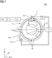
- the CT system 100 comprises: an AP sensor 10, an IP sensor 11, an X-ray tube 12, a motor controller 13, a motor 14, a gantry 15, a plurality of check points 16, a reference check point 17 and a tension pulley 18.
- the gantry 15 consists of two parts: a rotary component and a static component, wherein the rotary component can rotate around the central axis of the gantry 15 in the X-Y plane of the X, Y and Z axes of the rectangular coordinate system shown in Fig. 1 , a plurality of check points 16 and a reference check point 17 are arranged on the outer circumferential surface of the rotary component, an X-ray tube 12 and a detector array are oppositely mounted on the inner circumference surface, an AP sensor 10 and an IP sensor 11 are arranged on the inner circumferential surface of the static component, and the two sensors are separated at a certain distance.
- a patient bed (not shown) is provided in the gantry 15, a patient can lie on the bed, and the bed can move in the Z-axis direction of the rectangular coordinate system.
- the rotary component of the gantry 15 can continuously rotate around the patient bed.
- the X-ray tube 12 is disposed on the inner circumferential surface of the rotary component of the gantry 15 and emits a sector X-ray beam to the detector array (not shown) which is opposite to the X-ray tube 12 and is located on the other side of the inner circumferential surface of the rotary component.
- the X-ray beam emitted from the X-ray tube 12 hits the detector array after passing through a patient and attenuating.
- the strength of the attenuated radiation beam received at the detector array depends on the patient caused energy attenuation of the X-ray beam.
- Each detector element of the detector array generates an independent electrical signal, and the electrical signal represents the measured strength of the X-ray beam after the attenuation.
- the image re-constructor (not shown) receives the sampled digital X-ray data from the analog-to-digital converter and performs a high-speed image reconstruction.
- the AP sensor 10 and the IP sensor 11 are adjacently disposed on the inner circumferential surface of the static component of the gantry 15.
- the plurality of check points 16 are arranged at even intervals on the outer circumferential surface of the rotary component.
- the AP sensor 10 and the IP sensor 11 are proximity switches
- the check points 16 are metal heads
- the reference check point 17 is a metal groove.
- the proximity switch is a position switch which can be operated without any direct mechanical contact with a moving component. When an object (for example, check points 16 and reference check point 17) approaches the sensing surface of the switch to a detectable distance, the switch can act without any mechanical contact or any pressure exerted, and thus the position and stroke of a moving mechanism can accurately be reflected.
- the AP sensor 10 will sense the check point 16, and the switch of the AP sensor 10 is in the ON state and outputs a high-level signal as a response signal; when the check point 16 departs from the AP sensor 10 and the distance away from the AP sensor 10 is greater than the preset detectable distance, the AP sensor 10 will fail to sense the check point and output a low-level signal.
- the IP sensor 11 outputs a high-level signal, and otherwise outputs a low-level signal all the time.
- Fig. 2 shows the pulse signals generated by the IP sensor 11 and the AP sensor 10.
- the IP sensor 11 When the X-ray tube 12 rotates once around the central axis of rotation of the gantry 15 along with the gantry 15, the IP sensor 11 generates only one pulse signal, namely, one high-level signal, while the AP sensor 10 generates a pulse train with a period T and the pulse train contains pulse signals whose number corresponds to the number of check points 16.
- the angle between every two check points 16 is determined by the number of check points 16. Supposing the number of check points 16 is n, the angle between every two check points 16 is 360/n degrees. From Fig. 2 , it can be seen that the pulse width of an AP signal is different from that of an IP signal. Because the number of check points 16 is different from the number of reference check points 17, the durations of response signals are different.
- the preset reference detectable distance can be used as a flag indicating the gantry 15 or the X-ray tube 12 rotating once. Therefore, a response signal from the IP sensor 11 can be expressed by use of IP.
- a response signal output from the AP sensor 10 is AP 0
- a response signal output from the IP sensor 11 is IP.
- n is the number of the check points 16. Only a part of AP is shown in Fig. 2 .
- the motor 14 is configured to control the speed of rotation and direction of rotation of the gantry 15 under the control of the motor controller 13, and thus further control the position of the X-ray tube 12 disposed on the gantry 15.
- the motor 14 has an encoder.
- the encoder is usually an incremental encoder and the encoder data output by the encoder is mainly the pulse count per rotation.
- the pulse count of the encoder data is shown by ED in Fig. 2 .
- the tension pulley 1819 is configured to control the degree of tightness of the belt connecting the gantry 15 and the motor 14.
- the motor controller 13 controls the running of the motor 14 to control the position of the X-ray tube 12 based on the AP signal acquired from the AP sensor 10, the IP signal acquired from the IP sensor 11 and encoder data of the motor 14.
- the motor controller 13 may be a PC, a workstation or a central processing unit (CPU) embedded in the CT system. In other embodiments of the disclosure, the motor controller 13 may also be a more advanced processing system, for example, a distributed processing system.
- the motor controller 13 utilizes the IP signal acquired from the IP sensor 11 and the AP signal acquired from the AP sensor 10 to calculate the homing positioning signal of the X-ray tube 12, that is to say, to find the APo signal. After determining the APo signal, the motor controller 13 utilizes the encoder data to calculate the pulse count of encoder data between AP signals, starting from AP 0 . As shown in Fig. 2 , the pulse count of encoder data between AP 0 and AP 1 is 1360, the pulse count of encoder data between APo and AP 2 is 2700, and the pulse count of encoder data between AP 0 and AP 3 is 4060.
- the pulse count of corresponding encoder data of an AP signal is utilized to position the X-ray tube 12.
- the calculated pulse counts are fine-tuned according to practical experience (for example, 1360 is fine-tuned to 1350, 2700 to 2708 and 4060 to 4070%) and are saved in a table as table data, as indicated by TD in Table 2.
- the motor controller 13 utilizes the AP signals recorded in the data table and the corresponding pulse count of encoder data to calibrate the actual position of the X-ray tube 12.
- the motor controller 13 is further configured to communicate with a storage device or memory (not shown).
- the storage device is used to store encoder data containing AP signals calculated by the motor controller 13.
- the storage device includes various computer memories for storing data.
- the storage device may be an independent component relative to the motor controller 13. However, it should be understood that the storage device may be an integrated part of the motor controller 13.
- the motor controller 13 is further configured to utilize encoder data containing AP signals stored in the storage device to control the running of the motor 14 so as to control the position of the X-ray tube 12.
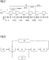
- Fig. 3 shows the closed-loop control of the rotation of the gantry according to one exemplary embodiment of the disclosure.
- the check points move toward the AP and IP sensors 32 one by one at certain intervals, wherein the AP sensor of the AP and IP sensors 32 generate n high-level signals in turn, while the IP sensor outputs one high-level signal when the distance between the reference check point and the IP sensor is greater than a preset reference detectable distance, and as the reference check point moves away, the IP sensor outputs low-level signals all the time until the current period ends.
- the AP and IP sensor 32 inputs detected AP signals and IP signals into the motor controller 13.
- the encoder data in the motor encoder 142 is also input into the motor controller 13.
- the motor controller 13 controls the running of the motor 14 to further control the positions of the belt/bearing 34 and the X-ray tube 12 based on the AP signal acquired from the AP sensor, the IP signal acquired from the IP sensor and encoder data acquired from the motor encoder 142.
- the motor controller 13 also controls other operations of the CT scanner 30, for example, steering.
- Fig. 4 shows the structure of the device of controlling the position of the X-ray tube of a CT system according to one exemplary embodiment of the disclosure.
- the device 40 comprises an acquisition module 42, a determination module 44, a calculation module 46 and a control module 48.
- the acquisition module 42 is configured to acquire an AP signal output by an AP sensor of the CT system, an IP signal output by an IP sensor and encoder data output by a motor
- the determination module 44 is configured to determine a homing positioning signal AP 0 of the AP signal based on the AP signal and the IP signal, wherein the homing positioning signal APo is used to determine the starting point of the period of rotation of the X-ray tube
- the calculation module 46 is configured to utilize the encoder data to calculate the encoder data containing AP signal based on the determined homing positioning signal AP 0
- the encoder data containing AP signal is the AP signal calibrated by use of the encoder data
- the control module 48 is configured to control the position of the X-ray tube based on the encoder data containing AP signal.
- the determination module 44 is further configured to detect whether the current IP signal is a high-level signal, and determine the high-level signal of the AP signal in the period in which the current IP signal is continuously a high-level signal to be the homing positioning signal AP 0 if the current IP signal is a high-level signal.
- the calculation module 46 is further configured to detect each high-level signal AP i of the AP signal in the period from the homing positioning signal APo to when the IP signal is a high-level signal again, respectively calculate the pulse count of the encoder data in the time segment between the homing positioning signal APo and each high-level signal AP i , and save the correspondence between the calculated pulse count of the encoder data and the AP signal as an encoder data containing AP signal.
- the control module is further configured to read the saved encoder data containing AP signal during the rotation of the gantry of the CT system, and utilizing the encoder data containing AP signal to calibrate the position of the X-ray tube so as to control the position of the X-ray tube.
- the position of the X-ray tube is calibrated by use of the pre-adjustment mode during the subsequent operation, and thus the precision of positioning the X-ray tube is improved.
- Fig. 5 is a flowchart of the method of controlling the position of the X-ray tube of the CT system according to one exemplary embodiment of the disclosure. As shown in Fig. 5 , the method comprises the following steps:
- Step S502 Acquire an AP signal output by an AP sensor of the CT system, an IP signal output by an IP sensor and encoder data output by a motor.
- the AP sensor When the distance between the AP sensor and any check point is less than a preset detectable distance, the AP sensor will sense the check point and generate a high-level signal, and when the distance is greater than the detectable distance, the AP sensor will fail to sense the check point and generate a low-level signal.
- the IP sensor When the distance between the IP sensor and the reference check point is less than a preset reference detectable distance, the IP sensor will sense the reference check point and generate a high-level signal, and when the distance is greater than the reference detectable distance, the IP sensor will fail to sense the reference check point and generate a low-level signal.
- the motor outputs encoder data representing the speed of rotation of the gantry.
- the AP signal, IP signal and encoder data are all transmitted to the motor controller.
- Step S504 Determine a homing positioning signal APo of the AP signal based on the AP signal and the IP signal, wherein the homing positioning signal APo is used to determine the starting point of the period of rotation of the X-ray tube.
- One rotation (namely, 360 degrees) of the X-ray tube around the central axis of the gantry is a period.
- the IP sensor When the distance between the reference check point and the IP sensor reaches a preset reference detectable distance, the IP sensor generates a high-level response signal.
- the distance between the check point and the AP sensor also reaches the preset detectable distance and the AP sensor generates a high-level signal.
- the high-level signal generated by the AP sensor is denoted by AP 0 and is used as the starting point of a rotation period.
- Step S506 Utilize the encoder data to calculate the encoder data containing AP signal based on the determined homing positioning signal AP 0 , wherein the encoder data containing AP signal is the AP signal calibrated by use of the encoder data.
- the motor controller After determining the APo signal, the motor controller utilizes the encoder data to calculate the pulse count of encoder data between AP signals, starting from APo. As shown in Fig. 2 , the pulse count of encoder data between APo and AP 1 is 1360, the pulse count of encoder data between APo and AP 2 is 2700, and the pulse count of encoder data between APo and AP 3 is 4060.
- Step S508 Save encoder data containing AP signals in a table.
- the calculated pulse counts are fine-tuned according to practical experience (for example, 1360 is fine-tuned to 1350, 2700 to 2708 and 4060 to 4070%) and are saved in the table as table data.
- Steps S502 to S508 are performed in the commissioning stage.
- Step S510 Control the position of the X-ray tube based on the encoder data containing AP signal.
- the motor controller 13 utilizes the AP signals recorded in the data table and the corresponding pulse count of encoder data to calibrate the actual position of the X-ray tube 12. This step is performed in the formal running stage of the CT scanner.
- the exemplary embodiments of the disclosure further provide a storage medium, and a computer program is stored in the storage medium.
- the computer program When executed, the computer program enables a processor to execute the method of controlling the position of the X-ray tube of the CT system in the embodiments of the disclosure.
- the above-mentioned storage medium includes, but is not limited to a USB disk, read-only memory (ROM), random access memory (RAM), mobile harddisk, magnetic disk or optical disk and other various media which can store program codes.
- the unit or module described as a separate part may be or may not be physically separated, and the part shown as a unit or module may be or may not be a physical unit or module, that is to say, it may be located at one place or may be distributed to a plurality of network units or modules. Part or all of the units or modules may be selected to realize the solution of the embodiment according to the actual requirements.
- each embodiment of the disclosure may be integrated into a processing unit or module, or each unit or module may physically exist separately, or two or more units or modules may be integrated into a unit or module.
- the above-mentioned integrated unit or module may be realized in the form of hardware or in the form of a software functional unit or module.
- the integrated unit may be stored in a computer-readable storage medium if it is realized in the form of a software functional unit and is marketed or used as an independent product.
- the technical solution of the disclosure or the part which makes contributions to the prior art, or all or part of the technical solution may essentially be represented in the form of a software product, and the computer software product is stored in a storage medium and comprises a plurality of instructions to enable a computer (PC, server or network equipment) to execute all or part of the steps of the method described in the embodiments of the disclosure.
- the above-mentioned storage medium includes a USB disk, read-only memory (ROM), random access memory (RAM), mobile harddisk, magnetic disk or optical disk and other various media which can store program codes.
Landscapes
- Health & Medical Sciences (AREA)
- Life Sciences & Earth Sciences (AREA)
- Engineering & Computer Science (AREA)
- Medical Informatics (AREA)
- Radiology & Medical Imaging (AREA)
- Molecular Biology (AREA)
- Biophysics (AREA)
- Nuclear Medicine, Radiotherapy & Molecular Imaging (AREA)
- Optics & Photonics (AREA)
- Pathology (AREA)
- Physics & Mathematics (AREA)
- Biomedical Technology (AREA)
- Heart & Thoracic Surgery (AREA)
- High Energy & Nuclear Physics (AREA)
- Surgery (AREA)
- Animal Behavior & Ethology (AREA)
- General Health & Medical Sciences (AREA)
- Public Health (AREA)
- Veterinary Medicine (AREA)
- Pulmonology (AREA)
- Theoretical Computer Science (AREA)
- Apparatus For Radiation Diagnosis (AREA)
Abstract
Description
- The disclosure relates to the technical field of medical devices, in particular to a method and a device of controlling the position of the X-ray tube in a computed tomography (CT) system, and a CT system.
- A CT system mainly comprises an X-ray tube, an X-ray detector array, a gantry and a patient bed. The X-ray tube and the X-ray detector array are disposed on the gantry rotating around the patient bed. Usually, the patient bed can move relative to the gantry. The X-ray tube generates a sector X-ray beam, and the X-ray beam passes one slice of an object (for example, a patient) which is being imaged and irradiates on the X-ray detector array. During CT imaging, the included angle between the X-ray beam and the body slice of the patient and the position of the patient bed relative to the gantry change continuously.
- The angular position (AP) of the X-ray tube is a very important parameter of the CT system and affects the imaging quality of the CT system. Especially, if the patient needs to use CT for X-ray interventional therapy, it is necessary to precisely position the X-ray tube.
- In order to obtain a precise angular position of the X-ray tube, a high-cost AP measurement system and a motor are adopted for a high-end CT system (for example, Definition system). Although a DC motor which can precisely position a sensor is used to acquire the precise position of the X-ray tube in a high-end CT system, it will take a lot of time and cost because the bearing needs to be assembled by use of DC driving. Usually, the minimum step of the position of the X-ray is 15 degrees and the accuracy is 2 degrees because of the limited number of check points in a low-end CT system. It is difficult to apply the interventional therapy in a low-end CT system because the low-end CT system cannot guarantee that the X-ray tube stops, with a step of 1 degree.
- No valid solution has been proposed for the above-mentioned problem.
- According to one aspect of the embodiments of the disclosure, a method of controlling the position of the X-ray tube of a CT system is provided, and the method comprises: acquiring an AP signal output by an AP sensor of the CT system, an IP signal output by an IP sensor and encoder data output by a motor, determining a homing positioning signal APo of the AP signal based on the AP signal and the IP signal, wherein the homing positioning signal APo is used to determine the starting point of the period of rotation of the X-ray tube, utilizing the encoder data to calculate the encoder data containing AP signal based on the determined homing positioning signal AP0, wherein the encoder data containing AP signal is the AP signal calibrated by use of the encoder data, and controlling the position of the X-ray tube based on the encoder data containing AP signal.
- Through the above-mentioned method, the technical problem that the CT system cannot precisely control the position of the X-ray tube in the related technology is solved and the position of the X-ray tube can precisely be controlled.
- In one exemplary embodiment of the disclosure, the AP signal is an angular position signal acquired after the AP sensor detects a plurality of check points arranged at even intervals on the outer circumferential surface of the gantry of the CT system, and/or the IP signal is an IP signal acquired after the IP sensor detects a reference check point arranged on the outer circumferential surface of the gantry of the CT system, and the IP signal is used to determine the period of rotation of the X-ray tube, and/or the encoder data is data output by the encoder of the motor and is used to control the speed of rotation of the X-ray tube.
- Through the above-mentioned method a positioning calculation error caused by a belt slip is eliminated, and thus the positioning accuracy of the X-ray tube is improved.
- In one exemplary embodiment of the disclosure, determining a homing positioning signal AP0 of the AP signal based on the AP signal and the IP signal comprises: detecting whether the current IP signal is a high-level signal, and determining the high-level signal of the AP signal in the period in which the current IP signal is continuously a high-level signal to be the homing positioning signal AP0 if the current IP signal is a high-level signal.
- Through the above-mentioned method, the step positioning precision of the X-ray tube is increased to 1 degree, without any new component added.
- In one exemplary embodiment of the disclosure, utilizing the encoder data to calculate the encoder data containing AP signal based on the determined homing positioning signal APo comprises: detecting each high-level signal APi of the AP signal in the period from the homing positioning signal APo to when the IP signal is a high-level signal again, respectively calculating the pulse count of the encoder data in the time segment between the homing positioning signal APo and each high-level signal APi, and saving the correspondence between the calculated pulse count of the encoder data and the AP signal as an encoder data containing AP signal.
- Through the above-mentioned method, the correspondence between an AP signal and encoder data can more precisely be calculated, and thus making it possible to precisely position the X-ray tube.
- In an exemplary embodiment of the disclosure, controlling the position of the X-ray tube based on the encoder data containing AP signal comprises: reading the saved encoder data containing AP signal during the rotation of the gantry of the CT system, and utilizing the encoder data containing AP signal to calibrate the position of the X-ray tube so as to control the position of the X-ray tube.
- Through the above-mentioned method, without any sensing device or component added, the position of the X-ray tube is calibrated by use of the pre-adjustment mode during the subsequent operation, and thus the precision of positioning the X-ray tube is improved.
- According to another aspect of the embodiments of the disclosure, a device of controlling the position of the X-ray tube of a CT system is provided, and the device comprises: an acquisition module, configured to acquire an AP signal output by an AP sensor of the CT system, an IP signal output by an IP sensor and encoder data output by a motor, a determination module, configured to determine a homing positioning signal APo of the AP signal based on the AP signal and the IP signal, wherein the homing positioning signal APo is used to determine the starting point of the period of rotation of the X-ray tube, a calculation module, configured to utilize the encoder data to calculate the encoder data containing AP signal based on the determined homing positioning signal AP0, wherein the encoder data containing AP signal is the AP signal calibrated by use of the encoder data, and a control module, configured to control the position of the X-ray tube based on the encoder data containing AP signal.
- Through the above-mentioned structure, the technical problem that the CT system cannot precisely control the position of the X-ray tube in the related technology is solved and the position of the X-ray tube can precisely be controlled. In one exemplary embodiment of the disclosure, the determination module is further configured to detect whether the current IP signal is a high-level signal, and determine the high-level signal of the AP signal in the period in which the current IP signal is continuously a high-level signal to be the homing positioning signal AP0 if the current IP signal is a high-level signal.
- Through the above-mentioned structure, the step positioning precision of the X-ray tube is increased to 1 degree, without any new component added.
- In one exemplary embodiment of the disclosure, the calculation module is further configured to detect each high-level signal APi of the AP signal in the period from the homing positioning signal AP0 to when the IP signal is a high-level signal again, respectively calculate the pulse count of the encoder data in the time segment between the homing positioning signal AP0 and each high-level signal APi, and save the correspondence between the calculated pulse count of the encoder data and the AP signal as an encoder data containing AP signal.
- Through the above-mentioned structure, the correspondence between an AP signal and encoder data can more precisely be calculated, and thus making it possible to precisely position the X-ray tube.
- In one exemplary embodiment of the disclosure, the control module is further configured to read the saved encoder data containing AP signal during the rotation of the gantry of the CT system, and utilize the encoder data containing AP signal to calibrate the position of the X-ray tube so as to control the position of the X-ray tube.
- Through the above-mentioned structure, without any sensing device or component added, the position of the X-ray tube is calibrated by use of the pre-adjustment mode during the subsequent operation, and thus the precision of positioning the X-ray tube is improved.
- According to a further aspect of the disclosure, a CT system is provided and the CT system comprises: a gantry, an AP sensor, an IP sensor, a motor and a motor controller, wherein the AP sensor is configured to detect a plurality of check points arranged at even intervals on the outer circumferential surface of the gantry to acquire an AP signal, the IP sensor is configured to detect a reference check point arranged on the outer circumferential surface of the gantry to acquire an IP signal, the motor is configured to output encoder data of the motor, and the motor controller is implemented as the above-mentioned device.
- Through the above-mentioned CT system, the technical problem that the CT system cannot precisely control the position of the X-ray tube in the related technology is solved and the position of the X-ray tube can precisely be controlled. According to a fourth aspect of the disclosure, a computer-readable storage medium is provided, a computer instruction is stored in the computer-readable storage medium, and when executed, the instruction enables a processor to execute the above-mentioned method.
- The drawings constituting a part of the disclosure are provided to help understand the disclosure, and the exemplary embodiments of the disclosure and the description thereof are used to explain the disclosure, but do not constitute improper restrictions of the disclosure. In the drawings,
-
Fig. 1 shows the structure of the CT system according to one exemplary embodiment of the disclosure, -
Fig. 2 shows a pulse signal according to one exemplary embodiment of the disclosure, -
Fig. 3 shows the closed-loop control of the rotation of the gantry according to one exemplary embodiment of the disclosure, -
Fig. 4 shows the structure of the device of controlling the position of the X-ray tube of a CT system according to one exemplary embodiment of the disclosure, and -
Fig. 5 is a flowchart of the method of controlling the position of the X-ray tube of a CT system according to one exemplary embodiment of the disclosure, - 100:
- CT system
- 10:
- AP sensor
- 11:
- IP sensor
- 12:
- X-ray tube
- 13:
- Motor controller
- 14:
- Motor
- 15:
- Gantry
- 16:
- Check point
- 17:
- Reference check point
- 18:
- Tension pulley
- AP:
- AP signal
- TD:
- Table data
- ED:
- Encoder data
- 30:
- CT scanner
- 32:
- AP & IP sensors
- 34:
- Belt/bearing
- 142:
- Motor encoder
- 40:
- Device
- 42:
- Acquisition module
- 44:
- Determination module
- 46:
- Calculation module
- 48:
- Control module
- To help those skilled in the art to better understand the technical solution of the disclosure, the technical solution in the embodiments of the disclosure will be clearly and completely described below in combination with the drawings in the embodiments of the disclosure.
- It should be noted that the terms "comprise" and "have" and their variants are intended to cover non-exclusive inclusions. For example, the process or method comprising a series of steps or the system, product or device comprising a series of modules or units are unnecessarily limited to those clearly-listed steps or modules or units, but may comprise other steps or modules or units which are not clearly listed or are intrinsic to the process, method, product or device.
- According to one exemplary embodiment of the disclosure, a CT system is provided. As shown in
Fig. 1 , theCT system 100 comprises: anAP sensor 10, anIP sensor 11, anX-ray tube 12, amotor controller 13, amotor 14, agantry 15, a plurality of check points 16, areference check point 17 and atension pulley 18. - The
gantry 15 consists of two parts: a rotary component and a static component, wherein the rotary component can rotate around the central axis of thegantry 15 in the X-Y plane of the X, Y and Z axes of the rectangular coordinate system shown inFig. 1 , a plurality of check points 16 and areference check point 17 are arranged on the outer circumferential surface of the rotary component, anX-ray tube 12 and a detector array are oppositely mounted on the inner circumference surface, anAP sensor 10 and anIP sensor 11 are arranged on the inner circumferential surface of the static component, and the two sensors are separated at a certain distance. A patient bed (not shown) is provided in thegantry 15, a patient can lie on the bed, and the bed can move in the Z-axis direction of the rectangular coordinate system. The rotary component of thegantry 15 can continuously rotate around the patient bed. - The
X-ray tube 12 is disposed on the inner circumferential surface of the rotary component of thegantry 15 and emits a sector X-ray beam to the detector array (not shown) which is opposite to theX-ray tube 12 and is located on the other side of the inner circumferential surface of the rotary component. The X-ray beam emitted from theX-ray tube 12 hits the detector array after passing through a patient and attenuating. The strength of the attenuated radiation beam received at the detector array depends on the patient caused energy attenuation of the X-ray beam. Each detector element of the detector array generates an independent electrical signal, and the electrical signal represents the measured strength of the X-ray beam after the attenuation. After that, the measured strength of each detector of the detector array is collected, and the measured strength is an analog electrical signal. Therefore, it is usually necessary to further send the measured strength to an analog-to-digital converter which digitalizes analog signals for an analog-digital conversion. The image re-constructor (not shown) receives the sampled digital X-ray data from the analog-to-digital converter and performs a high-speed image reconstruction. - The
AP sensor 10 and theIP sensor 11 are adjacently disposed on the inner circumferential surface of the static component of thegantry 15. The plurality of check points 16 are arranged at even intervals on the outer circumferential surface of the rotary component. In one exemplary embodiment of the disclosure, theAP sensor 10 and theIP sensor 11 are proximity switches, the check points 16 are metal heads, and thereference check point 17 is a metal groove. The proximity switch is a position switch which can be operated without any direct mechanical contact with a moving component. When an object (for example, checkpoints 16 and reference check point 17) approaches the sensing surface of the switch to a detectable distance, the switch can act without any mechanical contact or any pressure exerted, and thus the position and stroke of a moving mechanism can accurately be reflected. - During the rotation of the
gantry 15, when the distance between acheck point 16 and theAP sensor 10 reaches a preset detectable distance, theAP sensor 10 will sense thecheck point 16, and the switch of theAP sensor 10 is in the ON state and outputs a high-level signal as a response signal; when thecheck point 16 departs from theAP sensor 10 and the distance away from theAP sensor 10 is greater than the preset detectable distance, theAP sensor 10 will fail to sense the check point and output a low-level signal. Alike, when the distance between thereference check point 17 and theIP sensor 11 is less than a preset reference detectable distance, theIP sensor 11 outputs a high-level signal, and otherwise outputs a low-level signal all the time. -
Fig. 2 shows the pulse signals generated by theIP sensor 11 and theAP sensor 10. When theX-ray tube 12 rotates once around the central axis of rotation of thegantry 15 along with thegantry 15, theIP sensor 11 generates only one pulse signal, namely, one high-level signal, while theAP sensor 10 generates a pulse train with a period T and the pulse train contains pulse signals whose number corresponds to the number of check points 16. The angle between every twocheck points 16 is determined by the number of check points 16. Supposing the number of check points 16 is n, the angle between every twocheck points 16 is 360/n degrees. FromFig. 2 , it can be seen that the pulse width of an AP signal is different from that of an IP signal. Because the number of check points 16 is different from the number of reference check points 17, the durations of response signals are different. - In addition, since only one
reference check point 17 is provided, there is only one chance that the distance between thereference check point 17 and theIP sensor 11 reaches the preset reference detectable distance when thegantry 15 rotates once. Thus, the preset reference detectable distance can be used as a flag indicating thegantry 15 or theX-ray tube 12 rotating once. Therefore, a response signal from theIP sensor 11 can be expressed by use of IP. InFig. 1 , when theX-ray tube 12 rotates clockwise from the 0° position, a response signal output from theAP sensor 10 is AP0, and a response signal output from theIP sensor 11 is IP. Since the check points 16 are arranged at even intervals on the outer circumferential surface of the rotary component of thegantry 15, the check points 16 move toward theAP sensor 10 one by one at certain intervals. Therefore, theAP sensor 10 will generate n high-level signals in turn, wherein n is the number of the check points 16. Only a part of AP is shown inFig. 2 . - The
motor 14 is configured to control the speed of rotation and direction of rotation of thegantry 15 under the control of themotor controller 13, and thus further control the position of theX-ray tube 12 disposed on thegantry 15. Themotor 14 has an encoder. The encoder is usually an incremental encoder and the encoder data output by the encoder is mainly the pulse count per rotation. The pulse count of the encoder data is shown by ED inFig. 2 . The tension pulley 1819 is configured to control the degree of tightness of the belt connecting thegantry 15 and themotor 14. - The
motor controller 13 controls the running of themotor 14 to control the position of theX-ray tube 12 based on the AP signal acquired from theAP sensor 10, the IP signal acquired from theIP sensor 11 and encoder data of themotor 14. Themotor controller 13 may be a PC, a workstation or a central processing unit (CPU) embedded in the CT system. In other embodiments of the disclosure, themotor controller 13 may also be a more advanced processing system, for example, a distributed processing system. - The
motor controller 13 utilizes the IP signal acquired from theIP sensor 11 and the AP signal acquired from theAP sensor 10 to calculate the homing positioning signal of theX-ray tube 12, that is to say, to find the APo signal. After determining the APo signal, themotor controller 13 utilizes the encoder data to calculate the pulse count of encoder data between AP signals, starting from AP0. As shown inFig. 2 , the pulse count of encoder data between AP0 and AP1 is 1360, the pulse count of encoder data between APo and AP2 is 2700, and the pulse count of encoder data between AP0 and AP3 is 4060. Since the speed of rotation in encoder data is stable and is free from influence of external factors such as a belt slip, it can be considered that no positioning error exists if the pulse count of corresponding encoder data of an AP signal is utilized to position theX-ray tube 12. The calculated pulse counts are fine-tuned according to practical experience (for example, 1360 is fine-tuned to 1350, 2700 to 2708 and 4060 to 4070...) and are saved in a table as table data, as indicated by TD in Table 2. During the positioning of theX-ray tube 12, themotor controller 13 utilizes the AP signals recorded in the data table and the corresponding pulse count of encoder data to calibrate the actual position of theX-ray tube 12. - The
motor controller 13 is further configured to communicate with a storage device or memory (not shown). The storage device is used to store encoder data containing AP signals calculated by themotor controller 13. The storage device includes various computer memories for storing data. The storage device may be an independent component relative to themotor controller 13. However, it should be understood that the storage device may be an integrated part of themotor controller 13. Themotor controller 13 is further configured to utilize encoder data containing AP signals stored in the storage device to control the running of themotor 14 so as to control the position of theX-ray tube 12. -
Fig. 3 shows the closed-loop control of the rotation of the gantry according to one exemplary embodiment of the disclosure. In one exemplary embodiment of the disclosure, when the gantry rotates clockwise, the check points move toward the AP andIP sensors 32 one by one at certain intervals, wherein the AP sensor of the AP andIP sensors 32 generate n high-level signals in turn, while the IP sensor outputs one high-level signal when the distance between the reference check point and the IP sensor is greater than a preset reference detectable distance, and as the reference check point moves away, the IP sensor outputs low-level signals all the time until the current period ends. The AP andIP sensor 32 inputs detected AP signals and IP signals into themotor controller 13. The encoder data in themotor encoder 142 is also input into themotor controller 13. Themotor controller 13 controls the running of themotor 14 to further control the positions of the belt/bearing 34 and theX-ray tube 12 based on the AP signal acquired from the AP sensor, the IP signal acquired from the IP sensor and encoder data acquired from themotor encoder 142. Themotor controller 13 also controls other operations of theCT scanner 30, for example, steering. -
Fig. 4 shows the structure of the device of controlling the position of the X-ray tube of a CT system according to one exemplary embodiment of the disclosure. As shown inFig. 4 , thedevice 40 comprises anacquisition module 42, adetermination module 44, acalculation module 46 and acontrol module 48. - In one exemplary embodiment of the disclosure, the
acquisition module 42 is configured to acquire an AP signal output by an AP sensor of the CT system, an IP signal output by an IP sensor and encoder data output by a motor, thedetermination module 44 is configured to determine a homing positioning signal AP0 of the AP signal based on the AP signal and the IP signal, wherein the homing positioning signal APo is used to determine the starting point of the period of rotation of the X-ray tube, thecalculation module 46 is configured to utilize the encoder data to calculate the encoder data containing AP signal based on the determined homing positioning signal AP0, wherein the encoder data containing AP signal is the AP signal calibrated by use of the encoder data, and thecontrol module 48 is configured to control the position of the X-ray tube based on the encoder data containing AP signal. - In one exemplary embodiment of the disclosure, the
determination module 44 is further configured to detect whether the current IP signal is a high-level signal, and determine the high-level signal of the AP signal in the period in which the current IP signal is continuously a high-level signal to be the homing positioning signal AP0 if the current IP signal is a high-level signal. Thecalculation module 46 is further configured to detect each high-level signal APi of the AP signal in the period from the homing positioning signal APo to when the IP signal is a high-level signal again, respectively calculate the pulse count of the encoder data in the time segment between the homing positioning signal APo and each high-level signal APi, and save the correspondence between the calculated pulse count of the encoder data and the AP signal as an encoder data containing AP signal. The control module is further configured to read the saved encoder data containing AP signal during the rotation of the gantry of the CT system, and utilizing the encoder data containing AP signal to calibrate the position of the X-ray tube so as to control the position of the X-ray tube. - Through the above-mentioned structure, without any sensing device or component added, the position of the X-ray tube is calibrated by use of the pre-adjustment mode during the subsequent operation, and thus the precision of positioning the X-ray tube is improved.
-
Fig. 5 is a flowchart of the method of controlling the position of the X-ray tube of the CT system according to one exemplary embodiment of the disclosure. As shown inFig. 5 , the method comprises the following steps: - Step S502: Acquire an AP signal output by an AP sensor of the CT system, an IP signal output by an IP sensor and encoder data output by a motor.
- When the distance between the AP sensor and any check point is less than a preset detectable distance, the AP sensor will sense the check point and generate a high-level signal, and when the distance is greater than the detectable distance, the AP sensor will fail to sense the check point and generate a low-level signal. When the distance between the IP sensor and the reference check point is less than a preset reference detectable distance, the IP sensor will sense the reference check point and generate a high-level signal, and when the distance is greater than the reference detectable distance, the IP sensor will fail to sense the reference check point and generate a low-level signal. The motor outputs encoder data representing the speed of rotation of the gantry. The AP signal, IP signal and encoder data are all transmitted to the motor controller.
- Step S504: Determine a homing positioning signal APo of the AP signal based on the AP signal and the IP signal, wherein the homing positioning signal APo is used to determine the starting point of the period of rotation of the X-ray tube.
- One rotation (namely, 360 degrees) of the X-ray tube around the central axis of the gantry is a period. When the distance between the reference check point and the IP sensor reaches a preset reference detectable distance, the IP sensor generates a high-level response signal. At this time, the distance between the check point and the AP sensor also reaches the preset detectable distance and the AP sensor generates a high-level signal. The high-level signal generated by the AP sensor is denoted by AP0 and is used as the starting point of a rotation period.
- Step S506: Utilize the encoder data to calculate the encoder data containing AP signal based on the determined homing positioning signal AP0, wherein the encoder data containing AP signal is the AP signal calibrated by use of the encoder data.
- After determining the APo signal, the motor controller utilizes the encoder data to calculate the pulse count of encoder data between AP signals, starting from APo. As shown in
Fig. 2 , the pulse count of encoder data between APo and AP1 is 1360, the pulse count of encoder data between APo and AP2 is 2700, and the pulse count of encoder data between APo and AP3 is 4060. - Step S508: Save encoder data containing AP signals in a table.
- The calculated pulse counts are fine-tuned according to practical experience (for example, 1360 is fine-tuned to 1350, 2700 to 2708 and 4060 to 4070...) and are saved in the table as table data.
- Steps S502 to S508 are performed in the commissioning stage.
- Step S510: Control the position of the X-ray tube based on the encoder data containing AP signal.
- During the positioning of the
X-ray tube 12, themotor controller 13 utilizes the AP signals recorded in the data table and the corresponding pulse count of encoder data to calibrate the actual position of theX-ray tube 12. This step is performed in the formal running stage of the CT scanner. - The exemplary embodiments of the disclosure further provide a storage medium, and a computer program is stored in the storage medium. When executed, the computer program enables a processor to execute the method of controlling the position of the X-ray tube of the CT system in the embodiments of the disclosure. In the above-mentioned embodiment, the above-mentioned storage medium includes, but is not limited to a USB disk, read-only memory (ROM), random access memory (RAM), mobile harddisk, magnetic disk or optical disk and other various media which can store program codes.
- It should be understood that the technical content disclosed in the embodiments of the disclosure can be realized in other ways. The above-described embodiments of the device are given only for illustrative purposes. The division of units or modules is only a logical function division, and other division methods may be used in the actual realization. For example, a plurality of units or modules or components may be combined or integrated into another system, or some features may be ignored or may not be executed. In addition, the shown or discussed couplings, or direct couplings or communication connections between them may be indirect couplings or communication connections, electrical or otherwise, through some interfaces, modules or units.
- The unit or module described as a separate part may be or may not be physically separated, and the part shown as a unit or module may be or may not be a physical unit or module, that is to say, it may be located at one place or may be distributed to a plurality of network units or modules. Part or all of the units or modules may be selected to realize the solution of the embodiment according to the actual requirements.
- In addition, the functional units or modules in each embodiment of the disclosure may be integrated into a processing unit or module, or each unit or module may physically exist separately, or two or more units or modules may be integrated into a unit or module. The above-mentioned integrated unit or module may be realized in the form of hardware or in the form of a software functional unit or module.
- The integrated unit may be stored in a computer-readable storage medium if it is realized in the form of a software functional unit and is marketed or used as an independent product. Based on such an understanding, the technical solution of the disclosure or the part which makes contributions to the prior art, or all or part of the technical solution may essentially be represented in the form of a software product, and the computer software product is stored in a storage medium and comprises a plurality of instructions to enable a computer (PC, server or network equipment) to execute all or part of the steps of the method described in the embodiments of the disclosure. The above-mentioned storage medium includes a USB disk, read-only memory (ROM), random access memory (RAM), mobile harddisk, magnetic disk or optical disk and other various media which can store program codes.
- Only preferred embodiments of the present disclosure are described above. It should be pointed out that those skilled in the art can make improvements and modifications without departing from the principle of the disclosure and these improvements and modifications should also fall within the scope of protection of the disclosure.
Claims (10)
- A method of controlling the position of the X-ray tube of a CT system, comprising:acquiring an AP signal output by an AP sensor of the CT system, an IP signal output by an IP sensor and encoder data output by a motor,determining a homing positioning signal AP0 of the AP signal based on the AP signal and the IP signal, wherein the homing positioning signal AP0 is used to determine the starting point of the period of rotation of the X-ray tube,utilizing the encoder data to calculate the encoder data containing AP signal based on the determined homing positioning signal AP0, wherein the encoder data containing AP signal is the AP signal calibrated by use of the encoder data, and
controlling the position of the X-ray tube based on the encoder data containing AP signal. - The method as claimed in claim 1, whereinthe AP signal is an angular position signal acquired after the AP sensor detects a plurality of check points arranged at even intervals on the outer circumferential surface of the gantry of the CT system, and/orthe IP signal is an index pulse (IP) signal acquired after the IP sensor detects a reference check point arranged on the outer circumferential surface of the gantry of the CT system, and the IP signal is used to determine the period of rotation of the X-ray tube, and/orthe encoder data is data output by the encoder of the motor and is used to control the speed of rotation of the X-ray tube.
- The method as claimed in claim 1 or 2, wherein determining a homing positioning signal AP0 of the AP signal based on the AP signal and the IP signal comprises:detecting whether the current IP signal is a high-level signal, anddetermining the high-level signal of the AP signal in the period in which the current IP signal is continuously a high-level signal to be the homing positioning signal AP0 if the current IP signal is a high-level signal.
- The method as claimed in claim 3, wherein utilizing the encoder data to calculate the encoder data containing AP signal based on the determined homing positioning signal AP0 comprises:detecting each high-level signal APi of the AP signal in the period from the homing positioning signal AP0 to when the IP signal is a high-level signal again,respectively calculating the pulse count of the encoder data in the time segment between the homing positioning signal AP0 and each high-level signal APi, andsaving the correspondence between the calculated pulse count of the encoder data and the AP signal as an encoder data containing AP signal.
- The method as claimed in any one of claims 1 - 4, wherein controlling the position of the X-ray tube based on the encoder data containing AP signal comprises:reading the saved encoder data containing AP signal during the rotation of the gantry of the CT system, andutilizing the encoder data containing AP signal to calibrate the position of the X-ray tube so as to control the position of the X-ray tube.
- A device of controlling the position of the X-ray tube of a CT system, comprising:an acquisition module, configured to acquire an AP signal output by an AP sensor of the CT system, an IP signal output by an IP sensor and encoder data output by a motor,a determination module, configured to determine a homing positioning signal AP0 of the AP signal based on the AP signal and the IP signal, wherein the homing positioning signal AP0 is used to determine the starting point of the period of rotation of the X-ray tube,a calculation module, configured to utilize the encoder data to calculate the encoder data containing AP signal based on the determined homing positioning signal AP0, wherein the encoder data containing AP signal is the AP signal calibrated by use of the encoder data, anda control module, configured to control the position of the X-ray tube based on the encoder data containing AP signal.
- The device as claimed in claim 6, wherein the determination module is further configured todetect whether the current IP signal is a high-level signal, anddetermine the high-level signal of the AP signal in the period in which the current IP signal is continuously a high-level signal to be the homing positioning signal AP0 if the current IP signal is a high-level signal.
- The device as claimed in claim 6 or 7, wherein the calculation module is further configured todetect each high-level signal APi of the AP signal in the period from the homing positioning signal AP0 to when the IP signal is a high-level signal again,respectively calculate the pulse count of the encoder data in the time segment between the homing positioning signal AP0 and each high-level signal APi, andsave the correspondence between the calculated pulse count of the encoder data and the AP signal as an encoder data containing AP signal.
- The device as claimed in any one of claims 6 - 8, wherein the control module is further configured toread the saved encoder data containing AP signal during the rotation of the gantry of the CT system, andutilize the encoder data containing AP signal to calibrate the position of the X-ray tube so as to control the position of the X-ray tube.
- A CT system, comprising a gantry, an AP sensor, an IP sensor, a motor and a motor controller, whereinthe AP sensor is configured to detect a plurality of check points arranged at even intervals on the outer circumferential surface of the gantry to acquire an AP signal,the IP sensor is configured to detect a reference check point arranged on the outer circumferential surface of the gantry to acquire an IP signal,the motor is configured to output encoder data of the motor, andthe motor controller is implemented as the device as claimed in any of claims 6 to 9.
Applications Claiming Priority (1)
| Application Number | Priority Date | Filing Date | Title |
|---|---|---|---|
| CN202011339298.0A CN112472113B (en) | 2020-11-25 | 2020-11-25 | CT system and method and device for controlling position of X-ray tube thereof |
Publications (3)
| Publication Number | Publication Date |
|---|---|
| EP4005486A1 true EP4005486A1 (en) | 2022-06-01 |
| EP4005486B1 EP4005486B1 (en) | 2025-03-05 |
| EP4005486C0 EP4005486C0 (en) | 2025-03-05 |
Family
ID=74934255
Family Applications (1)
| Application Number | Title | Priority Date | Filing Date |
|---|---|---|---|
| EP21210214.9A Active EP4005486B1 (en) | 2020-11-25 | 2021-11-24 | Ct system and method and device controlling the position of the x-ray tube thereof |
Country Status (3)
| Country | Link |
|---|---|
| US (1) | US11896412B2 (en) |
| EP (1) | EP4005486B1 (en) |
| CN (1) | CN112472113B (en) |
Citations (4)
| Publication number | Priority date | Publication date | Assignee | Title |
|---|---|---|---|---|
| US20010055362A1 (en) * | 2000-06-22 | 2001-12-27 | Tetsuyuki Takanashi | X-ray CT apparatus |
| DE102004042486A1 (en) * | 2004-08-31 | 2006-03-16 | Siemens Ag | Apparatus and method for measuring the angle of rotation of a rotor relative to a stator |
| DE102016218888B3 (en) * | 2016-09-29 | 2017-11-16 | Siemens Healthcare Gmbh | Method for determining the angle of rotation of a rotor-stator device, and slip ring assembly and computed tomography |
| WO2018093933A1 (en) * | 2016-11-15 | 2018-05-24 | Reflexion Medical, Inc. | System for emission-guided high-energy photon delivery |
Family Cites Families (4)
| Publication number | Priority date | Publication date | Assignee | Title |
|---|---|---|---|---|
| US5175754A (en) * | 1992-05-11 | 1992-12-29 | General Electric Company | Gantry position reference for tomographic scanners |
| JP5627295B2 (en) * | 2010-05-31 | 2014-11-19 | 株式会社日立メディコ | X-ray CT system |
| US20120209555A1 (en) * | 2011-02-16 | 2012-08-16 | David Tang | Rotation sensor for use with an imaging system and method for using the same |
| JP6577487B2 (en) * | 2014-11-27 | 2019-09-18 | 株式会社日立製作所 | X-ray CT apparatus and control method thereof |
-
2020
- 2020-11-25 CN CN202011339298.0A patent/CN112472113B/en active Active
-
2021
- 2021-11-24 EP EP21210214.9A patent/EP4005486B1/en active Active
- 2021-11-24 US US17/534,509 patent/US11896412B2/en active Active
Patent Citations (4)
| Publication number | Priority date | Publication date | Assignee | Title |
|---|---|---|---|---|
| US20010055362A1 (en) * | 2000-06-22 | 2001-12-27 | Tetsuyuki Takanashi | X-ray CT apparatus |
| DE102004042486A1 (en) * | 2004-08-31 | 2006-03-16 | Siemens Ag | Apparatus and method for measuring the angle of rotation of a rotor relative to a stator |
| DE102016218888B3 (en) * | 2016-09-29 | 2017-11-16 | Siemens Healthcare Gmbh | Method for determining the angle of rotation of a rotor-stator device, and slip ring assembly and computed tomography |
| WO2018093933A1 (en) * | 2016-11-15 | 2018-05-24 | Reflexion Medical, Inc. | System for emission-guided high-energy photon delivery |
Also Published As
| Publication number | Publication date |
|---|---|
| EP4005486B1 (en) | 2025-03-05 |
| CN112472113B (en) | 2024-04-23 |
| US11896412B2 (en) | 2024-02-13 |
| US20220160317A1 (en) | 2022-05-26 |
| EP4005486C0 (en) | 2025-03-05 |
| CN112472113A (en) | 2021-03-12 |
Similar Documents
| Publication | Publication Date | Title |
|---|---|---|
| US7797981B2 (en) | Position measuring device | |
| US10670383B2 (en) | Calibrating and operating rotary devices, in particular for rotating probe heads and/or probes of coordinate measuring machines | |
| US6591217B1 (en) | Method and device for detecting errors in the signals of a system for monitoring the rotation of a shaft | |
| JP2015503748A (en) | High resolution absolute encoder | |
| US20080002871A1 (en) | Procedure for detecting a deviation in a x-ray system from a target position | |
| US20040234025A1 (en) | Processes and a device for determining the actual position of a structure of an object to be examined | |
| KR102086357B1 (en) | Using Absolute Encoders for Motor Absolute position and Finding minimum Absolute Encoders Resolution | |
| IL273264B2 (en) | Method for automatic detection of instrument orientation for robotic surgery | |
| JP6485410B2 (en) | X-ray inspection apparatus and X-ray inspection method | |
| JP2952313B2 (en) | Method and system for correcting image defects of scanner due to movement of scanner | |
| EP2489310A1 (en) | Rotation sensor for use with an imaging system and method for using the same | |
| US20200301033A1 (en) | Calibration and quality control of a nuclear-medicine (n-m) radio imaging system | |
| CN107132239B (en) | Alignment system of medical equipment and position precision monitoring method of motion unit | |
| CN100512759C (en) | Table equipment identifying method and medical imaging equipment | |
| CN101496726A (en) | Method and apparatus for acquiring projected angle in image reconstruction | |
| CN113639622A (en) | Position sensor, position measuring method, position measuring device, and storage medium | |
| EP4005486B1 (en) | Ct system and method and device controlling the position of the x-ray tube thereof | |
| US5239297A (en) | Position-encoded screw and method and system for calibrating a position-encoded screw | |
| EP2669701B1 (en) | Calibration to improve weather radar positioning determination | |
| JPH11309139A (en) | Computer tomography system | |
| US7278786B2 (en) | Method and apparatus for triggering image acquisition in a C-arm system by a rotary encoder | |
| CN114285347A (en) | Closed-loop control method for treatment couch, control device, and storage medium | |
| JP2013002874A (en) | Encoder | |
| JP2000193783A (en) | Method and apparatus for measuring non-homogeneity of the surface of a reactor structural component | |
| JPS60236010A (en) | Measuring device for position |
Legal Events
| Date | Code | Title | Description |
|---|---|---|---|
| PUAI | Public reference made under article 153(3) epc to a published international application that has entered the european phase |
Free format text: ORIGINAL CODE: 0009012 |
|
| STAA | Information on the status of an ep patent application or granted ep patent |
Free format text: STATUS: REQUEST FOR EXAMINATION WAS MADE |
|
| 17P | Request for examination filed |
Effective date: 20211124 |
|
| AK | Designated contracting states |
Kind code of ref document: A1 Designated state(s): AL AT BE BG CH CY CZ DE DK EE ES FI FR GB GR HR HU IE IS IT LI LT LU LV MC MK MT NL NO PL PT RO RS SE SI SK SM TR |
|
| RBV | Designated contracting states (corrected) |
Designated state(s): AL AT BE BG CH CY CZ DE DK EE ES FI FR GB GR HR HU IE IS IT LI LT LU LV MC MK MT NL NO PL PT RO RS SE SI SK SM TR |
|
| RAP1 | Party data changed (applicant data changed or rights of an application transferred) |
Owner name: SIEMENS HEALTHINEERS AG |
|
| GRAP | Despatch of communication of intention to grant a patent |
Free format text: ORIGINAL CODE: EPIDOSNIGR1 |
|
| STAA | Information on the status of an ep patent application or granted ep patent |
Free format text: STATUS: GRANT OF PATENT IS INTENDED |
|
| RIC1 | Information provided on ipc code assigned before grant |
Ipc: A61B 6/03 20060101ALN20240917BHEP Ipc: A61B 6/58 20240101ALI20240917BHEP Ipc: A61B 6/00 20060101AFI20240917BHEP |
|
| INTG | Intention to grant announced |
Effective date: 20240930 |
|
| GRAS | Grant fee paid |
Free format text: ORIGINAL CODE: EPIDOSNIGR3 |
|
| GRAA | (expected) grant |
Free format text: ORIGINAL CODE: 0009210 |
|
| STAA | Information on the status of an ep patent application or granted ep patent |
Free format text: STATUS: THE PATENT HAS BEEN GRANTED |
|
| AK | Designated contracting states |
Kind code of ref document: B1 Designated state(s): AL AT BE BG CH CY CZ DE DK EE ES FI FR GB GR HR HU IE IS IT LI LT LU LV MC MK MT NL NO PL PT RO RS SE SI SK SM TR |
|
| REG | Reference to a national code |
Ref country code: GB Ref legal event code: FG4D |
|
| REG | Reference to a national code |
Ref country code: CH Ref legal event code: EP |
|
| REG | Reference to a national code |
Ref country code: IE Ref legal event code: FG4D |
|
| REG | Reference to a national code |
Ref country code: DE Ref legal event code: R096 Ref document number: 602021027086 Country of ref document: DE |
|
| U01 | Request for unitary effect filed |
Effective date: 20250305 |
|
| U07 | Unitary effect registered |
Designated state(s): AT BE BG DE DK EE FI FR IT LT LU LV MT NL PT RO SE SI Effective date: 20250312 |
|
| PG25 | Lapsed in a contracting state [announced via postgrant information from national office to epo] |
Ref country code: RS Free format text: LAPSE BECAUSE OF FAILURE TO SUBMIT A TRANSLATION OF THE DESCRIPTION OR TO PAY THE FEE WITHIN THE PRESCRIBED TIME-LIMIT Effective date: 20250605 |
|
| PG25 | Lapsed in a contracting state [announced via postgrant information from national office to epo] |
Ref country code: ES Free format text: LAPSE BECAUSE OF FAILURE TO SUBMIT A TRANSLATION OF THE DESCRIPTION OR TO PAY THE FEE WITHIN THE PRESCRIBED TIME-LIMIT Effective date: 20250305 |
|
| PG25 | Lapsed in a contracting state [announced via postgrant information from national office to epo] |
Ref country code: NO Free format text: LAPSE BECAUSE OF FAILURE TO SUBMIT A TRANSLATION OF THE DESCRIPTION OR TO PAY THE FEE WITHIN THE PRESCRIBED TIME-LIMIT Effective date: 20250605 |
|
| PG25 | Lapsed in a contracting state [announced via postgrant information from national office to epo] |
Ref country code: HR Free format text: LAPSE BECAUSE OF FAILURE TO SUBMIT A TRANSLATION OF THE DESCRIPTION OR TO PAY THE FEE WITHIN THE PRESCRIBED TIME-LIMIT Effective date: 20250305 |
|
| PG25 | Lapsed in a contracting state [announced via postgrant information from national office to epo] |
Ref country code: GR Free format text: LAPSE BECAUSE OF FAILURE TO SUBMIT A TRANSLATION OF THE DESCRIPTION OR TO PAY THE FEE WITHIN THE PRESCRIBED TIME-LIMIT Effective date: 20250606 |
|
| PG25 | Lapsed in a contracting state [announced via postgrant information from national office to epo] |
Ref country code: SM Free format text: LAPSE BECAUSE OF FAILURE TO SUBMIT A TRANSLATION OF THE DESCRIPTION OR TO PAY THE FEE WITHIN THE PRESCRIBED TIME-LIMIT Effective date: 20250305 |
|
| PG25 | Lapsed in a contracting state [announced via postgrant information from national office to epo] |
Ref country code: PL Free format text: LAPSE BECAUSE OF FAILURE TO SUBMIT A TRANSLATION OF THE DESCRIPTION OR TO PAY THE FEE WITHIN THE PRESCRIBED TIME-LIMIT Effective date: 20250305 |
|
| PG25 | Lapsed in a contracting state [announced via postgrant information from national office to epo] |
Ref country code: CZ Free format text: LAPSE BECAUSE OF FAILURE TO SUBMIT A TRANSLATION OF THE DESCRIPTION OR TO PAY THE FEE WITHIN THE PRESCRIBED TIME-LIMIT Effective date: 20250305 |
|
| PG25 | Lapsed in a contracting state [announced via postgrant information from national office to epo] |
Ref country code: SK Free format text: LAPSE BECAUSE OF FAILURE TO SUBMIT A TRANSLATION OF THE DESCRIPTION OR TO PAY THE FEE WITHIN THE PRESCRIBED TIME-LIMIT Effective date: 20250305 |
|
| PG25 | Lapsed in a contracting state [announced via postgrant information from national office to epo] |
Ref country code: IS Free format text: LAPSE BECAUSE OF FAILURE TO SUBMIT A TRANSLATION OF THE DESCRIPTION OR TO PAY THE FEE WITHIN THE PRESCRIBED TIME-LIMIT Effective date: 20250705 |
|
| U20 | Renewal fee for the european patent with unitary effect paid |
Year of fee payment: 5 Effective date: 20251120 |
|
| PLBE | No opposition filed within time limit |
Free format text: ORIGINAL CODE: 0009261 |
|
| STAA | Information on the status of an ep patent application or granted ep patent |
Free format text: STATUS: NO OPPOSITION FILED WITHIN TIME LIMIT |
|
| REG | Reference to a national code |
Ref country code: CH Ref legal event code: L10 Free format text: ST27 STATUS EVENT CODE: U-0-0-L10-L00 (AS PROVIDED BY THE NATIONAL OFFICE) Effective date: 20260114 |
|
| 26N | No opposition filed |
Effective date: 20251208 |