EP4003838B1 - Aircraft passenger seat unit with movable panel - Google Patents
Aircraft passenger seat unit with movable panel Download PDFInfo
- Publication number
- EP4003838B1 EP4003838B1 EP20751222.9A EP20751222A EP4003838B1 EP 4003838 B1 EP4003838 B1 EP 4003838B1 EP 20751222 A EP20751222 A EP 20751222A EP 4003838 B1 EP4003838 B1 EP 4003838B1
- Authority
- EP
- European Patent Office
- Prior art keywords
- seat
- seat unit
- movable panel
- panel
- aisle
- Prior art date
- Legal status (The legal status is an assumption and is not a legal conclusion. Google has not performed a legal analysis and makes no representation as to the accuracy of the status listed.)
- Active
Links
Images
Classifications
-
- B—PERFORMING OPERATIONS; TRANSPORTING
- B64—AIRCRAFT; AVIATION; COSMONAUTICS
- B64D—EQUIPMENT FOR FITTING IN OR TO AIRCRAFT; FLIGHT SUITS; PARACHUTES; ARRANGEMENT OR MOUNTING OF POWER PLANTS OR PROPULSION TRANSMISSIONS IN AIRCRAFT
- B64D11/00—Passenger or crew accommodation; Flight-deck installations not otherwise provided for
- B64D11/06—Arrangements of seats, or adaptations or details specially adapted for aircraft seats
- B64D11/0606—Arrangements of seats, or adaptations or details specially adapted for aircraft seats with privacy shells, screens, separators or the like
-
- B—PERFORMING OPERATIONS; TRANSPORTING
- B64—AIRCRAFT; AVIATION; COSMONAUTICS
- B64D—EQUIPMENT FOR FITTING IN OR TO AIRCRAFT; FLIGHT SUITS; PARACHUTES; ARRANGEMENT OR MOUNTING OF POWER PLANTS OR PROPULSION TRANSMISSIONS IN AIRCRAFT
- B64D11/00—Passenger or crew accommodation; Flight-deck installations not otherwise provided for
- B64D11/06—Arrangements of seats, or adaptations or details specially adapted for aircraft seats
-
- B—PERFORMING OPERATIONS; TRANSPORTING
- B64—AIRCRAFT; AVIATION; COSMONAUTICS
- B64D—EQUIPMENT FOR FITTING IN OR TO AIRCRAFT; FLIGHT SUITS; PARACHUTES; ARRANGEMENT OR MOUNTING OF POWER PLANTS OR PROPULSION TRANSMISSIONS IN AIRCRAFT
- B64D11/00—Passenger or crew accommodation; Flight-deck installations not otherwise provided for
- B64D11/06—Arrangements of seats, or adaptations or details specially adapted for aircraft seats
- B64D11/0602—Seat modules, i.e. seat systems including furniture separate from the seat itself
-
- B—PERFORMING OPERATIONS; TRANSPORTING
- B64—AIRCRAFT; AVIATION; COSMONAUTICS
- B64D—EQUIPMENT FOR FITTING IN OR TO AIRCRAFT; FLIGHT SUITS; PARACHUTES; ARRANGEMENT OR MOUNTING OF POWER PLANTS OR PROPULSION TRANSMISSIONS IN AIRCRAFT
- B64D11/00—Passenger or crew accommodation; Flight-deck installations not otherwise provided for
- B64D11/06—Arrangements of seats, or adaptations or details specially adapted for aircraft seats
- B64D11/0602—Seat modules, i.e. seat systems including furniture separate from the seat itself
- B64D11/0604—Seat modules, i.e. seat systems including furniture separate from the seat itself including a bed, e.g. cocoon type passenger seat modules
-
- B—PERFORMING OPERATIONS; TRANSPORTING
- B64—AIRCRAFT; AVIATION; COSMONAUTICS
- B64D—EQUIPMENT FOR FITTING IN OR TO AIRCRAFT; FLIGHT SUITS; PARACHUTES; ARRANGEMENT OR MOUNTING OF POWER PLANTS OR PROPULSION TRANSMISSIONS IN AIRCRAFT
- B64D11/00—Passenger or crew accommodation; Flight-deck installations not otherwise provided for
- B64D11/06—Arrangements of seats, or adaptations or details specially adapted for aircraft seats
- B64D11/0639—Arrangements of seats, or adaptations or details specially adapted for aircraft seats with features for adjustment or converting of seats
-
- B—PERFORMING OPERATIONS; TRANSPORTING
- B64—AIRCRAFT; AVIATION; COSMONAUTICS
- B64D—EQUIPMENT FOR FITTING IN OR TO AIRCRAFT; FLIGHT SUITS; PARACHUTES; ARRANGEMENT OR MOUNTING OF POWER PLANTS OR PROPULSION TRANSMISSIONS IN AIRCRAFT
- B64D11/00—Passenger or crew accommodation; Flight-deck installations not otherwise provided for
- B64D11/06—Arrangements of seats, or adaptations or details specially adapted for aircraft seats
- B64D11/0639—Arrangements of seats, or adaptations or details specially adapted for aircraft seats with features for adjustment or converting of seats
- B64D11/064—Adjustable inclination or position of seats
-
- B—PERFORMING OPERATIONS; TRANSPORTING
- B64—AIRCRAFT; AVIATION; COSMONAUTICS
- B64D—EQUIPMENT FOR FITTING IN OR TO AIRCRAFT; FLIGHT SUITS; PARACHUTES; ARRANGEMENT OR MOUNTING OF POWER PLANTS OR PROPULSION TRANSMISSIONS IN AIRCRAFT
- B64D11/00—Passenger or crew accommodation; Flight-deck installations not otherwise provided for
- B64D11/06—Arrangements of seats, or adaptations or details specially adapted for aircraft seats
- B64D11/0639—Arrangements of seats, or adaptations or details specially adapted for aircraft seats with features for adjustment or converting of seats
- B64D11/0641—Seats convertible into beds
-
- B—PERFORMING OPERATIONS; TRANSPORTING
- B64—AIRCRAFT; AVIATION; COSMONAUTICS
- B64D—EQUIPMENT FOR FITTING IN OR TO AIRCRAFT; FLIGHT SUITS; PARACHUTES; ARRANGEMENT OR MOUNTING OF POWER PLANTS OR PROPULSION TRANSMISSIONS IN AIRCRAFT
- B64D11/00—Passenger or crew accommodation; Flight-deck installations not otherwise provided for
- B64D11/06—Arrangements of seats, or adaptations or details specially adapted for aircraft seats
- B64D11/0639—Arrangements of seats, or adaptations or details specially adapted for aircraft seats with features for adjustment or converting of seats
- B64D11/0643—Adjustable foot or leg rests
-
- B—PERFORMING OPERATIONS; TRANSPORTING
- B64—AIRCRAFT; AVIATION; COSMONAUTICS
- B64D—EQUIPMENT FOR FITTING IN OR TO AIRCRAFT; FLIGHT SUITS; PARACHUTES; ARRANGEMENT OR MOUNTING OF POWER PLANTS OR PROPULSION TRANSMISSIONS IN AIRCRAFT
- B64D11/00—Passenger or crew accommodation; Flight-deck installations not otherwise provided for
- B64D11/06—Arrangements of seats, or adaptations or details specially adapted for aircraft seats
- B64D11/0646—Seats characterised by special features of stationary arms, foot or head rests
Definitions
- the present invention concerns aircraft passenger seat units. More particularly, this invention concerns an aircraft passenger seat unit with a movable panel.
- Business class seating generally aims to provide aircraft passengers with maximum comfort and privacy.
- the design of aircraft passenger seat units for business class seating is of course constrained by the limited availability of space within an aircraft cabin.
- the limited availability of space means that some aircraft seat unit configurations provide restricted access to the aircraft seats contained therein, which can pose a problem for persons with reduced mobility, especially wheelchair users.
- US 2013/241247 A1 discloses an aircraft passenger suite including a privacy screen slidable between an open and closed position to open and close an opening to the suite.
- the present invention seeks to mitigate the above-mentioned problems. Alternatively or additionally, the present invention seeks to provide an improved aircraft passenger seat unit.
- the present invention provides, according to a first aspect, an aircraft passenger seat unit, configured for use adjacent an aisle of an aircraft cabin.
- the seat unit comprises a seat, an aisle side, a foot well, a footrest positioned within the foot well, a wall, and a movable panel.
- the foot well is defined by the movable panel which is movable with respect to the footrest between a closed position in which the movable panel at least partially encloses a side of the footrest and an open position in which the movable panel at least partially exposes the side of the footrest such that, in use, when the panel is in the open position, a passenger can access the seat from an aisle through the partially exposed side of the footrest.
- the movable panel is positioned along the aisle side of the seat unit such that movable panel at least partially encloses the side of the footrest to block access to the side of the footrest from the aisle when in the closed position.
- the movable panel and the wall are spaced apart along the aisle side of the seat unit and the space between the movable panel and the wall defines an access path that provides passenger access into the seat unit from the first side of the seat unit.
- the seat comprises a seat pan and a backrest, the seat having an upright sitting configuration in which the backrest is substantially upright.
- the seat is movable in an upright sitting configuration between a first position in which the seat pan is spaced apart from the footrest by a first distance, and a second position in which the seat pan is spaced apart from the footrest by a second distance.
- the second distance is less than the first distance and no more than 15 centimetres.
- the invention provides a seat unit comprising a movable panel that is movable to provide access to the foot rest from a side of the seat unit where such access would normally be blocked by the panel.
- a passenger can thereby access the seat from an aisle through the partially exposed side of the footrest.
- a passenger could sit upon the seat and move their legs into the seat unit via the exposed side of the foot rest.
- Such an arrangement is particularly advantageous for passengers with reduced mobility, for example wheelchair users or those requiring a helper, who, due to restricted space within the seat unit, may find it difficult to access the seat and/or foot rest without a side of the footrest being exposed.
- the seat unit may be a business class seat unit.
- the upright sitting position of the seat may be a taxi, take-off and landing (TTL) position.
- TTL take-off and landing
- the seat may have a lie-flat bed-mode configuration in which the back rest is reclined to a position in which it is substantially parallel and level with the seat pan.
- the seat pan in the second position of the seat, is spaced apart from the footrest by a second distance of no more than 10 centimetres.
- the second distance is substantially zero, such that seat pan and footrest are substantially in contact with one another when the seat is in the second position.
- the seat pan and footrest form a contiguous surface when the seat is in the second position.
- the first distance is more than 30 centimetres.
- the first position of the seat may correspond to a taxi, take-off, and landing position.
- the seat may face in a direction defining a seat axis.
- the seat may be movable along the seat axis towards or away from the footrest when the seat is moved between the first and second positions.
- the seat may face in a direction towards the first side of the seat unit.
- the seat may be configured to face in a direction towards an aisle of an aircraft cabin.
- the seat is moveable in an upright configuration from a first position to a second position in which the seat pan closer the footrest so that, in use, a passenger can more easily access the seat from an aisle of the aircraft. Furthermore, if there is not enough room between the seat pan and the footrest for a passenger's legs when the seat is in the second position, the movable panel can be moved to the open position so that the passenger's legs can be moved into the seat unit and their feet placed upon the footrest. A passenger with reduced mobility can thereby sit upon the seat pan directly from aisle, without having to first enter the space within the seat unit. This arrangement is particularly advantageous where the passenger is a wheelchair user because the passenger can be transferred from an aisle adjacent the seat unit directly into the seat in an upright sitting position.
- the wall at least partially encloses a side of the seat when the seat is in the first position, the wall thereby blocking access to the seat from an aisle when in the first position.
- the wall does not enclose the side of the seat when the seat is in the second position so that a passenger can access the seat from an aisle when the seat is in the second position.
- the wall may be a privacy screen.
- the wall may be a console.
- a privacy screen or console is often positioned between the seat and the aisle to enclose the seat unit and provide the seat unit with privacy.
- a passenger can only access the seat from an aisle by moving into the space directly in front of the seat.
- a seat unit arrangement comprising a wall where there is limited space within the seat unit for wheel chair access, or for a passenger and a helper
- a preferred embodiment of the invention provides an arrangement in which it is possible to bring the seat to a position in which it is directly adjacent to the aisle, and no longer blocked by the wall.
- the seat is adjacent to the access path when in the second position so that a passenger can access the seat from a first side of the seat unit via the access path when the seat is in the second position.
- the first side of the seat unit may be an aisle side configured to be positioned adjacent an aisle in use.
- the seat unit may comprise a console comprising a table surface for use by a passenger of the seat unit.
- the console may be at least partially formed by the wall.
- the console may comprise an upper surface forming a table surface.
- the console may stow a deployable meal table.
- the aircraft passenger seat unit is configured to be positioned directly adjacent to and in front of a further, substantially identical aircraft seat unit, wherein the console is at least partially formed by the movable panel of the further seat unit.
- the seat unit may be a first seat unit.
- the further seat unit may be a second seat unit.
- the footrest of the second seat unit may be positioned within the console of the first seat unit.
- the seat unit comprises a shell, wherein the shell forms a console of the seat unit and a movable panel of the further seat unit.
- the shell may further comprise a dividing wall that is configured to be positioned at the rear of the aircraft passenger seat unit, between the seat unit and the further seat unit.
- the movable panel may be movably mounted via a hinge.
- the movable panel may function as a footrest access door.
- the movable panel may be mounted via a hinge and configured to be moved between the closed position and open position about a horizontal axis located towards the bottom of the panel.
- the hinge may be positioned along a bottom edge of the movable panel.
- the movable panel may be mounted via a hinge and configured to be moved between the closed position and open position about a vertical axis located towards a side of the panel.
- the hinge may be positioned along a side edge of the movable panel.
- the movable panel may be mounted via a hinge to a wall at least partially forming a foot well in which the footrest is contained.
- the movable panel may at least partially form the foot well when the movable panel is in the closed position.
- the movable panel may be mounted to the remainder of the shell via a hinge.
- the seat unit comprises a lock system configured to lock the movable panel in the closed position.
- the lock system may comprise a plurality of latches positioned on the movable panel and configured to engage with a structure of the seat unit to lock the movable panel in the closed position.
- the lock system may comprise a plurality of latches positioned on a structure of the seat unit and configured to engage with the movable panel to lock the movable panel in the closed position.
- the structure may be a shell.
- the structure may be one or more walls. The one or more walls may form at least part of a foot well of the seat unit.
- the plurality of latches may be positioned along the top, bottom, and/or both side edges of the movable panel. There may be four latches. There may be two latches positioned along a top edge of the panel. There may be two latches positioned along a bottom edge of the panel. There may be two latches positioned along each of two opposing side edges of the panel.
- the lock system comprises an actuatable member operable to disengage the latches so that the movable panel can be moved from the closed position to the open position.
- the actuatable member may be a release handle.
- the actuatable member may be a button.
- the actuatable member may be a lever.
- the actuatable member is positioned on a surface of the movable panel that is adjacent the footrest when the panel is in the closed position.
- the panel may comprise an aisle-side surface and an opposite, non-aisle-side surface.
- the aisle-side surface may be positioned adjacent an aisle of an aircraft cabin in use when the movable panel is in the closed position.
- the non-aisle-side surface may be positioned adjacent the footrest in use when the movable panel is in the closed position.
- the actuatable member may be positioned on the non-aisle-side surface of the movable panel.
- the actuatable member may be located within a foot well when the movable panel is in the closed position.
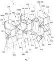
- a first aircraft passenger seat unit 100 is shown in Figure 1 positioned directly adjacent to and in front of a second, substantially identical seat unit 200.
- the seat units 100, 200 are arranged in a column adjacent an aisle 600 in an aircraft cabin 1. Because the seat units 100, 200 are substantially identical only the first seat unit 100 will be described. However, in Figures 1 to 4 features of the second seat unit 200 that are in common with the first seat unit 100 have been labelled with the same reference numeral but with the prefix "2" instead of "1".
- the second seat unit 200 comprises a seat 210 whereas the first seat unit 100 comprises a seat 110.
- a third substantially identical seat unit 300 and a fourth substantially identical seat unit 400 are also partially shown in Figures 1 to 5 , where the third seat unit 300 and fourth seat unit 400 have features that are in common with the first seat unit 100, those features have been labelled with the same reference numerals but with the respective prefixes "3" and "4"instead of " 1".
- the term “aisle-side” is used to refer to the side of a feature of a seat unit that is closest to the aisle 600 and, similarly, “non-aisle-side” is used to refer to the side of a feature that is furthest away from the aisle 600.
- the seat 110 of the seat unit 100 comprises an aisle side 110A that is closest the aisle 600 and a non-aisle-side 110B, on the opposite side of the seat 110 that is furthest away from the aisle 600.
- the first seat unit 100 comprises a seat 110 that is enclosed at a front of the seat unit 100 by a first shell 900A and enclosed at a rear of the seat unit 100 by a second shell 900B.
- the first and second shells 900A, 900B are substantially identical and each comprise features that form part of the seat units positioned on either side of the respective shells 900A, 900B.
- the second shell 900B comprises a partition that forms a rear privacy wall 105 of the first seat unit 100 and that also forms a front privacy wall 206 of the second seat unit 200.
- the second shell 900B comprises a rear privacy wall 105 that is positioned between the first seat unit 100 and the second seat unit 200 to enclose the seat 110 of the first seat unit 100 at the rear of the first seat unit 100, and a console 103 that provides a table surface 107 positioned on an aisle-side 110A of the seat 110.
- the first shell 900A comprises a front privacy wall 106 that is positioned in front of the seat 110, between the first seat unit 100 and a third seat unit 300, the third seat unit 300 being positioned directly adjacent to and in front of the first seat unit 100 and being only partially shown in Figures 1 to 3 .
- the first shell 900A also comprises a footrest 109 positioned within a foot well 111, the footrest 109 being positioned in front of the seat 110 and thereby being usable by a passenger of the seat 110.
- the foot well 111 of the first seat unit 100 forms the console 303 of the third seat unit 300.
- the foot well 211 of the second seat unit 200 forms the console 103 of the first seat unit 100.
- the foot well 111 is defined on an aisle-side by a movable panel 113 that encloses the footrest 109 on an aisle-side and which blocks access to the footrest 109 from the aisle 600, as can be seen in Figures 1 and 2 .
- the panel 113 is spaced-apart from the console along the aisle-side of the seat unit 100 to define an access path 115 between the panel 113 and console 103, the access path 115 providing passenger access into the seat unit from the aisle 600.
- the seat 100 comprises an upright sitting configuration in which the back rest 117 is positioned substantially upright, as shown in Figures 1 to 3 , and a lie-flat bed-mode configuration, which is not shown in the figures, in which the back rest 117 is reclined to a position in which it is substantially level with the seat pan 119.
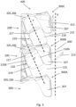
- the aisle 600 defines a longitudinal axis X along the aircraft cabin 1 and the seat 110 faces towards the aisle 600 in a direction defining a seat axis Y, the seat axis Y being angled by approximately 22 degrees to the longitudinal axis X.
- the seat 110 is moveable along the seat axis Y between a first position in which the seat is located towards the rear of the seat unit and a second position in which the seat is located towards the front of the seat unit.
- the seat 110 of the first seat unit 100 is shown as in the first position, and the console 103 is positioned between the aisle-side 110A of the seat 110 and the aisle 600, thereby blocking direct access to the seat 110 from the aisle 600.
- the seat 210 of the second seat unit 200 is shown as in the second position. The seat 210 has been moved forwards within the seat unit 200 so that the seat pan 219 of the seat 210 is positioned adjacent to the passenger access path 215 and so that the console 203 no longer blocks access to the seat 210 from the aisle 600.
- the seat pan 219 of the seat 210 is directly adjacent to and in contact with the footrest 209 when the seat 210 is in the second position. Therefore, with the seat 210 in the second position, the seat pan 219 and footrest 109 form a contiguous surface. In this configuration a passenger cannot sit upon the seat pan 219 facing in a direction along the seat axis Y with their feet resting upon the cabin floor because there is no room for the legs of the passenger between the seat pan 219 and the footrest 209.
- the panel 213 that encloses the aisle-side of the footrest 209 is configured to be movable between a closed position in which the panel 213 encloses the aisle-side of the footrest 209 and an open position in which the panel 213 is moved to expose the aisle-side of the footrest 209 such that the aisle-side of the footrest 209 is accessible directly from the aisle 600.
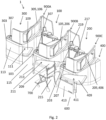
- the panel 113 of the first seat unit 100 is shown in the closed position and the panel 213 of the second seat unit 200 is shown in the open position.
- the seat units are arranged to provide passengers with reduced mobility, for example wheelchair users, with easy access to their seats from the aisle 600.
- the seat 210 must be moved from the first position into the second position and then the panel 213 must be moved from the closed position to the open position.
- a wheelchair 700 can then be positioned alongside the seat 210, as shown in figures 1 and 2 , so that a user of the wheelchair 700 can be transferred onto the seat 210 directly from aisle 600 and so that the legs of the wheelchair user can be transferred onto the footrest 209 directly from the aisle 600.
- the panel 213 can then be moved back to the closed position and the seat 210 can be moved back to the first position so that the wheelchair user is seated within the seat unit 200.
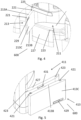
- the panel 213 of the second seat unit 200 is shown in more detail in Figure 4 .
- the panel 213 is mounted via a hinge positioned at a side edge of the panel 213 such that the panel 213 is openable and closable like a door.
- a lock system comprising a plurality of latches 221 that are positioned on the panel 213 and that are configured to be received within and engage with corresponding apertures 223 located in upper and lower walls 225, 227 of the foot well 211 that are positioned respectively above and below the panel 213 when the panel 213 is in the closed position.
- Two latches 221 are spaced apart along an upper edge 213A of the panel, and two latches 221 are spaced apart along an opposite lower edge 213B of the panel.
- the lock system is operable via a handle 229 positioned on the non-aisle-side 213C of the panel 213 i.e. the side of the panel 213 that is within the foot well 211 and not adjacent the aisle 600 when the panel 213 is in the closed position.
- the handle 229 When the handle 229 is pulled, each of the four latches 221 retract into the panel 213. Therefore, to release the panel 213 and move the panel 213 from the closed position to the open position, the handle 229 must be pulled to retract and thereby disengage the latches 221.
- the handle 229 when moving the panel 213 from the open position to the closed position, the handle 229 must be pulled to move the latches 221 into the panel so that the latches do not abut the walls 225, 227 positioned above and below the panel 213 and prevent the panel 213 from being moved to the closed position.
- a third shell 900C provides the console 203 of the second seat unit 200, said console 200 also forming the foot well 411 of a fourth seat unit 400, the fourth seat unit 400 being positioned directly adjacent to and behind the second seat unit 200 and being only partially shown in figures 1 to 3 .
- the fourth seat unit 400 has features in common with the second seat unit 200 as depicted in Figure 4 , those features have been labelled with the same reference numerals but with the prefix "4" instead of "2".
- the fourth seat unit 400 comprises a moveable panel 413 comprising a locking system that is substantially identical to the locking system as already described with respect to the second seat unit 200.
- the panel 413 is mounted along its lower edge 413B to the lower wall 427 via a hinge 431 so that the panel 413 is folded into the aisle 600 and downwardly when moving the panel 413 from the closed position to the open position. The panel 413 is then folded upwardly and out of the aisle 600 to move the panel from the open position to the closed position.
Landscapes
- Engineering & Computer Science (AREA)
- Aviation & Aerospace Engineering (AREA)
- Seats For Vehicles (AREA)
- Passenger Equipment (AREA)
Description
- The present invention concerns aircraft passenger seat units. More particularly, this invention concerns an aircraft passenger seat unit with a movable panel.
- Business class seating generally aims to provide aircraft passengers with maximum comfort and privacy. However, the design of aircraft passenger seat units for business class seating is of course constrained by the limited availability of space within an aircraft cabin. The limited availability of space means that some aircraft seat unit configurations provide restricted access to the aircraft seats contained therein, which can pose a problem for persons with reduced mobility, especially wheelchair users.
- Furthermore, United States Department of Transportation rules require that at least fifty percent of all aisle-seats within an aircraft cabin are able accommodate persons with reduced mobility. The cabin of an aircraft must satisfy this requirement if the aircraft is to operate from, or transit through the USA.
-
US 2013/241247 A1 discloses an aircraft passenger suite including a privacy screen slidable between an open and closed position to open and close an opening to the suite. - The present invention seeks to mitigate the above-mentioned problems. Alternatively or additionally, the present invention seeks to provide an improved aircraft passenger seat unit.
- The present invention provides, according to a first aspect, an aircraft passenger seat unit, configured for use adjacent an aisle of an aircraft cabin. The seat unit comprises a seat, an aisle side, a foot well, a footrest positioned within the foot well, a wall, and a movable panel. The foot well is defined by the movable panel which is movable with respect to the footrest between a closed position in which the movable panel at least partially encloses a side of the footrest and an open position in which the movable panel at least partially exposes the side of the footrest such that, in use, when the panel is in the open position, a passenger can access the seat from an aisle through the partially exposed side of the footrest. The movable panel is positioned along the aisle side of the seat unit such that movable panel at least partially encloses the side of the footrest to block access to the side of the footrest from the aisle when in the closed position. The movable panel and the wall are spaced apart along the aisle side of the seat unit and the space between the movable panel and the wall defines an access path that provides passenger access into the seat unit from the first side of the seat unit. The seat comprises a seat pan and a backrest, the seat having an upright sitting configuration in which the backrest is substantially upright. The seat is movable in an upright sitting configuration between a first position in which the seat pan is spaced apart from the footrest by a first distance, and a second position in which the seat pan is spaced apart from the footrest by a second distance. The second distance is less than the first distance and no more than 15 centimetres.
- The invention provides a seat unit comprising a movable panel that is movable to provide access to the foot rest from a side of the seat unit where such access would normally be blocked by the panel. A passenger can thereby access the seat from an aisle through the partially exposed side of the footrest. For example, a passenger could sit upon the seat and move their legs into the seat unit via the exposed side of the foot rest. Such an arrangement is particularly advantageous for passengers with reduced mobility, for example wheelchair users or those requiring a helper, who, due to restricted space within the seat unit, may find it difficult to access the seat and/or foot rest without a side of the footrest being exposed.
- The seat unit may be a business class seat unit. The upright sitting position of the seat may be a taxi, take-off and landing (TTL) position. The seat may have a lie-flat bed-mode configuration in which the back rest is reclined to a position in which it is substantially parallel and level with the seat pan.
- Advantageously, in the second position of the seat, the seat pan is spaced apart from the footrest by a second distance of no more than 10 centimetres. Preferably the second distance is substantially zero, such that seat pan and footrest are substantially in contact with one another when the seat is in the second position. Preferably the seat pan and footrest form a contiguous surface when the seat is in the second position. Preferably the first distance is more than 30 centimetres. The first position of the seat may correspond to a taxi, take-off, and landing position.
- The seat may face in a direction defining a seat axis. The seat may be movable along the seat axis towards or away from the footrest when the seat is moved between the first and second positions. The seat may face in a direction towards the first side of the seat unit. The seat may be configured to face in a direction towards an aisle of an aircraft cabin.
- The seat is moveable in an upright configuration from a first position to a second position in which the seat pan closer the footrest so that, in use, a passenger can more easily access the seat from an aisle of the aircraft. Furthermore, if there is not enough room between the seat pan and the footrest for a passenger's legs when the seat is in the second position, the movable panel can be moved to the open position so that the passenger's legs can be moved into the seat unit and their feet placed upon the footrest. A passenger with reduced mobility can thereby sit upon the seat pan directly from aisle, without having to first enter the space within the seat unit. This arrangement is particularly advantageous where the passenger is a wheelchair user because the passenger can be transferred from an aisle adjacent the seat unit directly into the seat in an upright sitting position.
- Preferably the wall at least partially encloses a side of the seat when the seat is in the first position, the wall thereby blocking access to the seat from an aisle when in the first position. Preferably the wall does not enclose the side of the seat when the seat is in the second position so that a passenger can access the seat from an aisle when the seat is in the second position. The wall may be a privacy screen. The wall may be a console.
- In prior art seat units a privacy screen or console is often positioned between the seat and the aisle to enclose the seat unit and provide the seat unit with privacy. In such arrangements, a passenger can only access the seat from an aisle by moving into the space directly in front of the seat. In a seat unit arrangement comprising a wall
where there is limited space within the seat unit for wheel chair access, or for a passenger and a helper, a preferred embodiment of the invention provides an arrangement in which it is possible to bring the seat to a position in which it is directly adjacent to the aisle, and no longer blocked by the wall. - Preferably the seat is adjacent to the access path when in the second position so that a passenger can access the seat from a first side of the seat unit via the access path when the seat is in the second position. The first side of the seat unit may be an aisle side configured to be positioned adjacent an aisle in use.
- The seat unit may comprise a console comprising a table surface for use by a passenger of the seat unit. The console may be at least partially formed by the wall. The console may comprise an upper surface forming a table surface. The console may stow a deployable meal table.
- Preferably the aircraft passenger seat unit is configured to be positioned directly adjacent to and in front of a further, substantially identical aircraft seat unit, wherein the console is at least partially formed by the movable panel of the further seat unit. The seat unit may be a first seat unit. The further seat unit may be a second seat unit. The footrest of the second seat unit may be positioned within the console of the first seat unit.
- Preferably the seat unit comprises a shell, wherein the shell forms a console of the seat unit and a movable panel of the further seat unit. The shell may further comprise a dividing wall that is configured to be positioned at the rear of the aircraft passenger seat unit, between the seat unit and the further seat unit.
- The movable panel may be movably mounted via a hinge. The movable panel may function as a footrest access door. The movable panel may be mounted via a hinge and configured to be moved between the closed position and open position about a horizontal axis located towards the bottom of the panel. The hinge may be positioned along a bottom edge of the movable panel. The movable panel may be mounted via a hinge and configured to be moved between the closed position and open position about a vertical axis located towards a side of the panel. The hinge may be positioned along a side edge of the movable panel. The movable panel may be mounted via a hinge to a wall at least partially forming a foot well in which the footrest is contained. The movable panel may at least partially form the foot well when the movable panel is in the closed position. Where the movable panel forms part
of a shell, the movable panel may be mounted to the remainder of the shell via a hinge. - Preferably the seat unit comprises a lock system configured to lock the movable panel in the closed position. The lock system may comprise a plurality of latches positioned on the movable panel and configured to engage with a structure of the seat unit to lock the movable panel in the closed position. Alternatively, the lock system may comprise a plurality of latches positioned on a structure of the seat unit and configured to engage with the movable panel to lock the movable panel in the closed position. The structure may be a shell. The structure may be one or more walls. The one or more walls may form at least part of a foot well of the seat unit. The plurality of latches may be positioned along the top, bottom, and/or both side edges of the movable panel. There may be four latches. There may be two latches positioned along a top edge of the panel. There may be two latches positioned along a bottom edge of the panel. There may be two latches positioned along each of two opposing side edges of the panel.
- Advantageously the lock system comprises an actuatable member operable to disengage the latches so that the movable panel can be moved from the closed position to the open position. The actuatable member may be a release handle. The actuatable member may be a button. The actuatable member may be a lever. Preferably the actuatable member is positioned on a surface of the movable panel that is adjacent the footrest when the panel is in the closed position. The panel may comprise an aisle-side surface and an opposite, non-aisle-side surface. The aisle-side surface may be positioned adjacent an aisle of an aircraft cabin in use when the movable panel is in the closed position. The non-aisle-side surface may be positioned adjacent the footrest in use when the movable panel is in the closed position. The actuatable member may be positioned on the non-aisle-side surface of the movable panel. The actuatable member may be located within a foot well when the movable panel is in the closed position.
- Embodiments of the present invention will now be described by way of example only with reference to the accompanying schematic drawings of which:
- Figure 1
- is a perspective view of an aircraft cabin comprising a first aircraft passenger seat unit according to an embodiment of the invention positioned directly adjacent to and in front of a second, substantially identical aircraft passenger seat unit;
- Figure 2
- is an alternative perspective view of the aircraft cabin arrangement of
Figure 1 ; - Figure 3
- is a plan view of the aircraft cabin of
Figure 1 ; - Figure 4
- is a detailed view of a movable panel of the second aircraft passenger seat unit; and
- Figure 5
- is a detailed view of the movable panel of a fourth aircraft passenger seat unit.
- A first aircraft
passenger seat unit 100 according to an embodiment of the invention is shown inFigure 1 positioned directly adjacent to and in front of a second, substantiallyidentical seat unit 200. Theseat units aisle 600 in anaircraft cabin 1. Because theseat units first seat unit 100 will be described. However, inFigures 1 to 4 features of thesecond seat unit 200 that are in common with thefirst seat unit 100 have been labelled with the same reference numeral but with the prefix "2" instead of "1". For example, thesecond seat unit 200 comprises aseat 210 whereas thefirst seat unit 100 comprises aseat 110. A third substantiallyidentical seat unit 300 and a fourth substantiallyidentical seat unit 400 are also partially shown inFigures 1 to 5 , where thethird seat unit 300 andfourth seat unit 400 have features that are in common with thefirst seat unit 100, those features have been labelled with the same reference numerals but with the respective prefixes "3" and "4"instead of " 1". - In the following description the term "aisle-side" is used to refer to the side of a feature of a seat unit that is closest to the
aisle 600 and, similarly, "non-aisle-side" is used to refer to the side of a feature that is furthest away from theaisle 600. For example, theseat 110 of theseat unit 100 comprises anaisle side 110A that is closest theaisle 600 and a non-aisle-side 110B, on the opposite side of theseat 110 that is furthest away from theaisle 600. - The
first seat unit 100 comprises aseat 110 that is enclosed at a front of theseat unit 100 by afirst shell 900A and enclosed at a rear of theseat unit 100 by asecond shell 900B. The first andsecond shells respective shells second shell 900B comprises a partition that forms a rear privacy wall 105 of thefirst seat unit 100 and that also forms a front privacy wall 206 of thesecond seat unit 200. - The
second shell 900B comprises a rear privacy wall 105 that is positioned between thefirst seat unit 100 and thesecond seat unit 200 to enclose theseat 110 of thefirst seat unit 100 at the rear of thefirst seat unit 100, and aconsole 103 that provides atable surface 107 positioned on an aisle-side 110A of theseat 110. Thefirst shell 900A comprises a front privacy wall 106 that is positioned in front of theseat 110, between thefirst seat unit 100 and athird seat unit 300, thethird seat unit 300 being positioned directly adjacent to and in front of thefirst seat unit 100 and being only partially shown inFigures 1 to 3 . Thefirst shell 900A also comprises afootrest 109 positioned within a foot well 111, thefootrest 109 being positioned in front of theseat 110 and thereby being usable by a passenger of theseat 110. As can be seen fromFigures 1 to 3 , the foot well 111 of thefirst seat unit 100 forms theconsole 303 of thethird seat unit 300. Similarly, the foot well 211 of thesecond seat unit 200 forms theconsole 103 of thefirst seat unit 100. - The foot well 111 is defined on an aisle-side by a
movable panel 113 that encloses thefootrest 109 on an aisle-side and which blocks access to thefootrest 109 from theaisle 600, as can be seen inFigures 1 and2 . Thepanel 113 is spaced-apart from the console along the aisle-side of theseat unit 100 to define anaccess path 115 between thepanel 113 andconsole 103, theaccess path 115 providing passenger access into the seat unit from theaisle 600. - The
seat 100 comprises an upright sitting configuration in which theback rest 117 is positioned substantially upright, as shown inFigures 1 to 3 , and a lie-flat bed-mode configuration, which is not shown in the figures, in which theback rest 117 is reclined to a position in which it is substantially level with theseat pan 119. - With reference to
Figure 3 , theaisle 600 defines a longitudinal axis X along theaircraft cabin 1 and theseat 110 faces towards theaisle 600 in a direction defining a seat axis Y, the seat axis Y being angled by approximately 22 degrees to the longitudinal axis X. To provide improved access to theseat 110 for passengers with reduced mobility, theseat 110 is moveable along the seat axis Y between a first position in which the seat is located towards the rear of the seat unit and a second position in which the seat is located towards the front of the seat unit. InFigures 1 to 3 theseat 110 of thefirst seat unit 100 is shown as in the first position, and theconsole 103 is positioned between the aisle-side 110A of theseat 110 and theaisle 600, thereby blocking direct access to theseat 110 from theaisle 600. InFigures 1 to 3 theseat 210 of thesecond seat unit 200 is shown as in the second position. Theseat 210 has been moved forwards within theseat unit 200 so that theseat pan 219 of theseat 210 is positioned adjacent to thepassenger access path 215 and so that theconsole 203 no longer blocks access to theseat 210 from theaisle 600. - With reference still to the
second seat unit 200, which is shown inFigures 1 to 3 with theseat 210 in the second position, theseat pan 219 of theseat 210 is directly adjacent to and in contact with thefootrest 209 when theseat 210 is in the second position. Therefore, with theseat 210 in the second position, theseat pan 219 andfootrest 109 form a contiguous surface. In this configuration a passenger cannot sit upon theseat pan 219 facing in a direction along the seat axis Y with their feet resting upon the cabin floor because there is no room for the legs of the passenger between theseat pan 219 and thefootrest 209. For this reason, thepanel 213 that encloses the aisle-side of thefootrest 209 is configured to be movable between a closed position in which thepanel 213 encloses the aisle-side of thefootrest 209 and an open position in which thepanel 213 is moved to expose the aisle-side of thefootrest 209 such that the aisle-side of thefootrest 209 is accessible directly from theaisle 600. InFigures 1 to 3 thepanel 113 of thefirst seat unit 100 is shown in the closed position and thepanel 213 of thesecond seat unit 200 is shown in the open position. - Being configured as described with movable panels adjacent the respective footrests, the seat units are arranged to provide passengers with reduced mobility, for example wheelchair users, with easy access to their seats from the
aisle 600. With continued reference to thesecond seat unit 200, to access theseat 210 directly from theaisle 600, theseat 210 must be moved from the first position into the second position and then thepanel 213 must be moved from the closed position to the open position. Awheelchair 700 can then be positioned alongside theseat 210, as shown infigures 1 and2 , so that a user of thewheelchair 700 can be transferred onto theseat 210 directly fromaisle 600 and so that the legs of the wheelchair user can be transferred onto thefootrest 209 directly from theaisle 600. Thepanel 213 can then be moved back to the closed position and theseat 210 can be moved back to the first position so that the wheelchair user is seated within theseat unit 200. - The
panel 213 of thesecond seat unit 200 is shown in more detail inFigure 4 . Thepanel 213 is mounted via a hinge positioned at a side edge of thepanel 213 such that thepanel 213 is openable and closable like a door. When thepanel 213 is in the closed position thepanel 213 is locked in place by a lock system comprising a plurality oflatches 221 that are positioned on thepanel 213 and that are configured to be received within and engage withcorresponding apertures 223 located in upper andlower walls panel 213 when thepanel 213 is in the closed position. Two latches 221 are spaced apart along anupper edge 213A of the panel, and twolatches 221 are spaced apart along an oppositelower edge 213B of the panel. The lock system is operable via ahandle 229 positioned on the non-aisle-side 213C of thepanel 213 i.e. the side of thepanel 213 that is within the foot well 211 and not adjacent theaisle 600 when thepanel 213 is in the closed position. When thehandle 229 is pulled, each of the fourlatches 221 retract into thepanel 213. Therefore, to release thepanel 213 and move thepanel 213 from the closed position to the open position, thehandle 229 must be pulled to retract and thereby disengage thelatches 221. Similarly, when moving thepanel 213 from the open position to the closed position, thehandle 229 must be pulled to move thelatches 221 into the panel so that the latches do not abut thewalls panel 213 and prevent thepanel 213 from being moved to the closed position. - As can be seen in
Figures 1 and2 , athird shell 900C provides theconsole 203 of thesecond seat unit 200, saidconsole 200 also forming the foot well 411 of afourth seat unit 400, thefourth seat unit 400 being positioned directly adjacent to and behind thesecond seat unit 200 and being only partially shown infigures 1 to 3 . InFigure 5 , where thefourth seat unit 400 has features in common with thesecond seat unit 200 as depicted inFigure 4 , those features have been labelled with the same reference numerals but with the prefix "4" instead of "2". Thefourth seat unit 400 comprises amoveable panel 413 comprising a locking system that is substantially identical to the locking system as already described with respect to thesecond seat unit 200. However, thepanel 413 is mounted along itslower edge 413B to thelower wall 427 via ahinge 431 so that thepanel 413 is folded into theaisle 600 and downwardly when moving thepanel 413 from the closed position to the open position. Thepanel 413 is then folded upwardly and out of theaisle 600 to move the panel from the open position to the closed position. Reference should be made to the claims for determining the true scope of the present invention.
Claims (12)
- An aircraft passenger seat unit (100), configured for use adjacent an aisle (600) of an aircraft cabin (1), wherein the seat unit comprises:- a seat (110) comprising a seat pan (119) and backrest (117) and having an upright sitting configuration in which the backrest is substantially upright,- an aisle side that is configured to be adjacent the aisle, in use,- a foot well (111),- a footrest (109) positioned within the foot well (111),- a wall, and- a moveable panel (113) positioned along the aisle side of the seat unit when in a closed position,
characterized in that: the foot well is defined by the movable panel which is movable with respect to the footrest between the closed position in which the movable panel at least partially encloses a side of the footrest to block access to the side of the footrest from the aisle and an open position in which the movable panel at least partially exposes the side of the footrest such that, in use, when the panel is in the open position, a passenger can access the seat unit from the aisle through the partially exposed side of the footrest,wherein the movable panel and the wall are spaced apart along the aisle side of the seat unit when the movable panel is in the closed position such that the space between the movable panel and the wall defines a passenger access path (115) into the seat unit from the aisle side of the seat unit, andwherein the seat is movable in the upright sitting configuration between a first position in which the seat pan is spaced apart from the footrest by a first distance, and a second position in which the seat pan is spaced apart from the footrest by a second distance, the second distance being less than the first distance and no more than 15 centimetres. - An aircraft passenger seat unit according to claim 1, wherein the seat faces in a direction defining a seat axis, and wherein the seat is movable along the seat axis towards or away from the footrest when the seat is moved between the first and second positions.
- An aircraft passenger seat unit according to claim 1 or 2, wherein the seat is adjacent to the access path when in the second position so that a passenger can access the seat from a first side of the seat unit via the access path when the seat is in the second position.
- An aircraft passenger seat unit according to any preceding claim, wherein the seat unit comprises a console (103) comprising a table surface (107) for use by a passenger of the seat unit and wherein the console is at least partially formed by the wall.
- An aircraft passenger seat unit according to claim 4, wherein the aircraft passenger seat unit is configured to be positioned directly adjacent to and in front of a further, substantially identical aircraft seat unit (200), and wherein the console is at least partially formed by a movable panel configured to define the foot well of the further seat unit.
- An aircraft passenger seat unit according to claim 5 further comprising a shell, wherein the shell forms the console of the seat unit and a movable panel configured to form the movable panel configured to define the foot well of the further seat unit.
- An aircraft passenger seat unit according to any preceding claim, wherein the movable panel is movably mounted via a hinge.
- An aircraft passenger seat unit according to claim 7, wherein the movable panel is configured to be moved between the closed position and open position about a horizontal axis located towards a bottom of the panel.
- An aircraft passenger seat unit according to claim 7, wherein the movable panel is configured to be moved between the closed position and open position about a vertical axis located towards a side of the panel.
- An aircraft passenger seat unit according to any preceding claim, wherein the seat unit comprises a locking system configured to lock the movable panel in the closed position, the locking system comprising:- a plurality of latches positioned on the movable panel and configured to engage with a structure of the seat unit to lock the movable panel in the closed position, or- a plurality of latches positioned on the structure of the seat unit and configured to engage with the movable panel to lock the movable panel in the closed position.
- An aircraft passenger seat unit according to claim 10, wherein the locking system comprises an actuatable member operable to disengage the latches so that the movable panel can be moved from the closed position to the open position.
- An aircraft passenger seat unit according to claim 11, wherein the actuatable member is positioned on a surface of the movable panel that is adjacent the footrest when the panel is in the closed position.
Applications Claiming Priority (2)
| Application Number | Priority Date | Filing Date | Title |
|---|---|---|---|
| GB1910905.7A GB2586043B (en) | 2019-07-31 | 2019-07-31 | Aircraft passenger seat unit with movable panel |
| PCT/GB2020/051755 WO2021019209A1 (en) | 2019-07-31 | 2020-07-23 | Aircraft passenger seat unit with movable panel |
Publications (2)
| Publication Number | Publication Date |
|---|---|
| EP4003838A1 EP4003838A1 (en) | 2022-06-01 |
| EP4003838B1 true EP4003838B1 (en) | 2024-03-13 |
Family
ID=67990521
Family Applications (1)
| Application Number | Title | Priority Date | Filing Date |
|---|---|---|---|
| EP20751222.9A Active EP4003838B1 (en) | 2019-07-31 | 2020-07-23 | Aircraft passenger seat unit with movable panel |
Country Status (4)
| Country | Link |
|---|---|
| US (1) | US12330790B2 (en) |
| EP (1) | EP4003838B1 (en) |
| GB (1) | GB2586043B (en) |
| WO (1) | WO2021019209A1 (en) |
Families Citing this family (2)
| Publication number | Priority date | Publication date | Assignee | Title |
|---|---|---|---|---|
| FR3125506B1 (en) * | 2021-07-23 | 2024-09-13 | Safran Seats | SEAT UNIT WITH RETRACTABLE PRIVACY SHELL |
| US12187434B2 (en) * | 2022-05-10 | 2025-01-07 | B/E Aerospace, Inc. | Persons with reduced mobility (PRM) suite access wall assembly |
Family Cites Families (18)
| Publication number | Priority date | Publication date | Assignee | Title |
|---|---|---|---|---|
| FR2980773B1 (en) * | 2011-09-30 | 2013-10-25 | Airbus Operations Sas | STRAPONTIN FOR AIRCRAFT COCKPIT AND FRONT PART OF AN AIRCRAFT EQUIPPED WITH SUCH A STRAPONTIN |
| CN104245507B (en) * | 2012-03-14 | 2017-08-01 | B/E航空公司 | Armrest assembly with deployable bed extension |
| EP2825458B1 (en) * | 2012-03-14 | 2018-11-28 | B/E Aerospace Inc. | Aircraft passenger suite with combination bed |
| US20150321592A1 (en) * | 2012-03-26 | 2015-11-12 | Zodiac Seats France | Tray table assembly |
| US9469405B2 (en) * | 2012-08-01 | 2016-10-18 | B/E Aerospace, Inc. | Passenger suite seating arrangement with moveable video monitor |
| US10179650B2 (en) * | 2016-03-10 | 2019-01-15 | B/E Aerospace, Inc. | Sliding seating unit panel for providing enhanced passenger ingress and egress |
| GB2548901B (en) * | 2016-04-01 | 2018-07-25 | Thompson Aero Seating Ltd | Aircraft passenger seating with dual-mode privacy door |
| GB201618272D0 (en) * | 2016-10-28 | 2016-12-14 | Acumen Design Ass Ltd | A passenger seating arrangement with inwardly facing seat units |
| EP3541654B1 (en) * | 2016-11-15 | 2023-08-16 | Safran Seats USA LLC | Mini suite emergency egress solutions |
| US11794902B2 (en) * | 2017-10-17 | 2023-10-24 | Airbus Canada Managing Gp Inc. | Lavatory enclosure reconfigurable to accommodate a stretcher |
| EP3546357B1 (en) * | 2018-03-30 | 2020-05-20 | Acumen Design Associates Ltd | A passenger seating arrangement having access for disabled passengers |
| GB2572446A (en) * | 2018-03-30 | 2019-10-02 | Acumen Design Ass Ltd | A passenger seating arrangement having access for disabled passengers |
| EP4046913B1 (en) * | 2018-04-04 | 2024-06-05 | Zephyr Aerospace, LLC | Vehicular seating suite configuration |
| EP3696086B1 (en) * | 2019-02-18 | 2024-01-24 | B/E Aerospace, Inc. | Arrangements for aircraft passenger cabins with privacy divider configurations |
| WO2020195945A1 (en) * | 2019-03-27 | 2020-10-01 | 株式会社ジャムコ | Aircraft seat structure |
| US11299274B1 (en) * | 2020-01-31 | 2022-04-12 | B/E Aerospace, Inc. | Aircraft passenger compartment with an accessibility door |
| FR3137662B1 (en) * | 2022-07-05 | 2024-10-11 | Safran Seats | SEAT UNIT WITH RETRACTABLE PRIVACY SHELL |
| US12377983B2 (en) * | 2023-03-08 | 2025-08-05 | B/E Aerospace, Inc. | Arrangements of lie flat seats with oblique front row |
-
2019
- 2019-07-31 GB GB1910905.7A patent/GB2586043B/en active Active
-
2020
- 2020-07-23 WO PCT/GB2020/051755 patent/WO2021019209A1/en not_active Ceased
- 2020-07-23 US US17/631,138 patent/US12330790B2/en active Active
- 2020-07-23 EP EP20751222.9A patent/EP4003838B1/en active Active
Also Published As
| Publication number | Publication date |
|---|---|
| US12330790B2 (en) | 2025-06-17 |
| GB201910905D0 (en) | 2019-09-11 |
| US20220258865A1 (en) | 2022-08-18 |
| GB2586043B (en) | 2023-05-10 |
| WO2021019209A1 (en) | 2021-02-04 |
| GB2586043A (en) | 2021-02-03 |
| EP4003838A1 (en) | 2022-06-01 |
Similar Documents
| Publication | Publication Date | Title |
|---|---|---|
| EP2289798B1 (en) | Seating for a passenger vehicle | |
| EP3092174B1 (en) | Aircraft passenger seating arrangement | |
| US5954401A (en) | Reclining seat and ottoman system for aircraft including amenity cabinet | |
| CN112105558B (en) | Passenger rides for disabled passengers | |
| US10752364B2 (en) | Variable seat module with an ottoman for a seating arrangement in a vehicle cabin | |
| US10399681B2 (en) | Seating arrangement in an aircraft cabin | |
| US20230331389A1 (en) | Configurable cabin attendant seat | |
| US10906651B2 (en) | Compact functional arrangement in a cabin of a vehicle and vehicle with such a functional arrangement | |
| US12344380B2 (en) | Aircraft cabin | |
| US12330790B2 (en) | Aircraft passenger seat unit with movable panel | |
| EP4506250A1 (en) | Conjoinable reverse herringbone passenger seat | |
| EP4003839B1 (en) | Aircraft passenger accommodation unit with moveable ottoman | |
| CN113950447A (en) | Seat assembly for the cabin of a means of transport | |
| CN112770973A (en) | Aircraft cabin | |
| EP4506251A1 (en) | Seat extension furniture for aircraft seats | |
| HK40032899A (en) | A passenger seating arrangement having access for disabled passengers | |
| US20210061468A1 (en) | Aircraft cabin, extending into a fuselage along an aircraft axis and associated business jet |
Legal Events
| Date | Code | Title | Description |
|---|---|---|---|
| STAA | Information on the status of an ep patent application or granted ep patent |
Free format text: STATUS: UNKNOWN |
|
| STAA | Information on the status of an ep patent application or granted ep patent |
Free format text: STATUS: THE INTERNATIONAL PUBLICATION HAS BEEN MADE |
|
| PUAI | Public reference made under article 153(3) epc to a published international application that has entered the european phase |
Free format text: ORIGINAL CODE: 0009012 |
|
| STAA | Information on the status of an ep patent application or granted ep patent |
Free format text: STATUS: REQUEST FOR EXAMINATION WAS MADE |
|
| 17P | Request for examination filed |
Effective date: 20220215 |
|
| AK | Designated contracting states |
Kind code of ref document: A1 Designated state(s): AL AT BE BG CH CY CZ DE DK EE ES FI FR GB GR HR HU IE IS IT LI LT LU LV MC MK MT NL NO PL PT RO RS SE SI SK SM TR |
|
| DAV | Request for validation of the european patent (deleted) | ||
| DAX | Request for extension of the european patent (deleted) | ||
| GRAP | Despatch of communication of intention to grant a patent |
Free format text: ORIGINAL CODE: EPIDOSNIGR1 |
|
| STAA | Information on the status of an ep patent application or granted ep patent |
Free format text: STATUS: GRANT OF PATENT IS INTENDED |
|
| INTG | Intention to grant announced |
Effective date: 20231013 |
|
| GRAS | Grant fee paid |
Free format text: ORIGINAL CODE: EPIDOSNIGR3 |
|
| GRAA | (expected) grant |
Free format text: ORIGINAL CODE: 0009210 |
|
| STAA | Information on the status of an ep patent application or granted ep patent |
Free format text: STATUS: THE PATENT HAS BEEN GRANTED |
|
| AK | Designated contracting states |
Kind code of ref document: B1 Designated state(s): AL AT BE BG CH CY CZ DE DK EE ES FI FR GB GR HR HU IE IS IT LI LT LU LV MC MK MT NL NO PL PT RO RS SE SI SK SM TR |
|
| REG | Reference to a national code |
Ref country code: GB Ref legal event code: FG4D |
|
| REG | Reference to a national code |
Ref country code: CH Ref legal event code: EP |
|
| REG | Reference to a national code |
Ref country code: DE Ref legal event code: R096 Ref document number: 602020027230 Country of ref document: DE |
|
| REG | Reference to a national code |
Ref country code: IE Ref legal event code: FG4D |
|
| PG25 | Lapsed in a contracting state [announced via postgrant information from national office to epo] |
Ref country code: LT Free format text: LAPSE BECAUSE OF FAILURE TO SUBMIT A TRANSLATION OF THE DESCRIPTION OR TO PAY THE FEE WITHIN THE PRESCRIBED TIME-LIMIT Effective date: 20240313 |
|
| REG | Reference to a national code |
Ref country code: LT Ref legal event code: MG9D |
|
| PG25 | Lapsed in a contracting state [announced via postgrant information from national office to epo] |
Ref country code: GR Free format text: LAPSE BECAUSE OF FAILURE TO SUBMIT A TRANSLATION OF THE DESCRIPTION OR TO PAY THE FEE WITHIN THE PRESCRIBED TIME-LIMIT Effective date: 20240614 |
|
| REG | Reference to a national code |
Ref country code: NL Ref legal event code: MP Effective date: 20240313 |
|
| PG25 | Lapsed in a contracting state [announced via postgrant information from national office to epo] |
Ref country code: HR Free format text: LAPSE BECAUSE OF FAILURE TO SUBMIT A TRANSLATION OF THE DESCRIPTION OR TO PAY THE FEE WITHIN THE PRESCRIBED TIME-LIMIT Effective date: 20240313 Ref country code: RS Free format text: LAPSE BECAUSE OF FAILURE TO SUBMIT A TRANSLATION OF THE DESCRIPTION OR TO PAY THE FEE WITHIN THE PRESCRIBED TIME-LIMIT Effective date: 20240613 |
|
| PG25 | Lapsed in a contracting state [announced via postgrant information from national office to epo] |
Ref country code: ES Free format text: LAPSE BECAUSE OF FAILURE TO SUBMIT A TRANSLATION OF THE DESCRIPTION OR TO PAY THE FEE WITHIN THE PRESCRIBED TIME-LIMIT Effective date: 20240313 |
|
| PG25 | Lapsed in a contracting state [announced via postgrant information from national office to epo] |
Ref country code: RS Free format text: LAPSE BECAUSE OF FAILURE TO SUBMIT A TRANSLATION OF THE DESCRIPTION OR TO PAY THE FEE WITHIN THE PRESCRIBED TIME-LIMIT Effective date: 20240613 Ref country code: NO Free format text: LAPSE BECAUSE OF FAILURE TO SUBMIT A TRANSLATION OF THE DESCRIPTION OR TO PAY THE FEE WITHIN THE PRESCRIBED TIME-LIMIT Effective date: 20240613 Ref country code: LT Free format text: LAPSE BECAUSE OF FAILURE TO SUBMIT A TRANSLATION OF THE DESCRIPTION OR TO PAY THE FEE WITHIN THE PRESCRIBED TIME-LIMIT Effective date: 20240313 Ref country code: HR Free format text: LAPSE BECAUSE OF FAILURE TO SUBMIT A TRANSLATION OF THE DESCRIPTION OR TO PAY THE FEE WITHIN THE PRESCRIBED TIME-LIMIT Effective date: 20240313 Ref country code: GR Free format text: LAPSE BECAUSE OF FAILURE TO SUBMIT A TRANSLATION OF THE DESCRIPTION OR TO PAY THE FEE WITHIN THE PRESCRIBED TIME-LIMIT Effective date: 20240614 Ref country code: FI Free format text: LAPSE BECAUSE OF FAILURE TO SUBMIT A TRANSLATION OF THE DESCRIPTION OR TO PAY THE FEE WITHIN THE PRESCRIBED TIME-LIMIT Effective date: 20240313 Ref country code: ES Free format text: LAPSE BECAUSE OF FAILURE TO SUBMIT A TRANSLATION OF THE DESCRIPTION OR TO PAY THE FEE WITHIN THE PRESCRIBED TIME-LIMIT Effective date: 20240313 Ref country code: BG Free format text: LAPSE BECAUSE OF FAILURE TO SUBMIT A TRANSLATION OF THE DESCRIPTION OR TO PAY THE FEE WITHIN THE PRESCRIBED TIME-LIMIT Effective date: 20240313 |
|
| REG | Reference to a national code |
Ref country code: AT Ref legal event code: MK05 Ref document number: 1665561 Country of ref document: AT Kind code of ref document: T Effective date: 20240313 |
|
| PG25 | Lapsed in a contracting state [announced via postgrant information from national office to epo] |
Ref country code: SE Free format text: LAPSE BECAUSE OF FAILURE TO SUBMIT A TRANSLATION OF THE DESCRIPTION OR TO PAY THE FEE WITHIN THE PRESCRIBED TIME-LIMIT Effective date: 20240313 Ref country code: LV Free format text: LAPSE BECAUSE OF FAILURE TO SUBMIT A TRANSLATION OF THE DESCRIPTION OR TO PAY THE FEE WITHIN THE PRESCRIBED TIME-LIMIT Effective date: 20240313 |
|
| PG25 | Lapsed in a contracting state [announced via postgrant information from national office to epo] |
Ref country code: NL Free format text: LAPSE BECAUSE OF FAILURE TO SUBMIT A TRANSLATION OF THE DESCRIPTION OR TO PAY THE FEE WITHIN THE PRESCRIBED TIME-LIMIT Effective date: 20240313 |
|
| PG25 | Lapsed in a contracting state [announced via postgrant information from national office to epo] |
Ref country code: NL Free format text: LAPSE BECAUSE OF FAILURE TO SUBMIT A TRANSLATION OF THE DESCRIPTION OR TO PAY THE FEE WITHIN THE PRESCRIBED TIME-LIMIT Effective date: 20240313 |
|
| PG25 | Lapsed in a contracting state [announced via postgrant information from national office to epo] |
Ref country code: IS Free format text: LAPSE BECAUSE OF FAILURE TO SUBMIT A TRANSLATION OF THE DESCRIPTION OR TO PAY THE FEE WITHIN THE PRESCRIBED TIME-LIMIT Effective date: 20240713 |
|
| PG25 | Lapsed in a contracting state [announced via postgrant information from national office to epo] |
Ref country code: PT Free format text: LAPSE BECAUSE OF FAILURE TO SUBMIT A TRANSLATION OF THE DESCRIPTION OR TO PAY THE FEE WITHIN THE PRESCRIBED TIME-LIMIT Effective date: 20240715 Ref country code: SM Free format text: LAPSE BECAUSE OF FAILURE TO SUBMIT A TRANSLATION OF THE DESCRIPTION OR TO PAY THE FEE WITHIN THE PRESCRIBED TIME-LIMIT Effective date: 20240313 |
|
| PG25 | Lapsed in a contracting state [announced via postgrant information from national office to epo] |
Ref country code: CZ Free format text: LAPSE BECAUSE OF FAILURE TO SUBMIT A TRANSLATION OF THE DESCRIPTION OR TO PAY THE FEE WITHIN THE PRESCRIBED TIME-LIMIT Effective date: 20240313 Ref country code: EE Free format text: LAPSE BECAUSE OF FAILURE TO SUBMIT A TRANSLATION OF THE DESCRIPTION OR TO PAY THE FEE WITHIN THE PRESCRIBED TIME-LIMIT Effective date: 20240313 |
|
| PG25 | Lapsed in a contracting state [announced via postgrant information from national office to epo] |
Ref country code: AT Free format text: LAPSE BECAUSE OF FAILURE TO SUBMIT A TRANSLATION OF THE DESCRIPTION OR TO PAY THE FEE WITHIN THE PRESCRIBED TIME-LIMIT Effective date: 20240313 |
|
| PG25 | Lapsed in a contracting state [announced via postgrant information from national office to epo] |
Ref country code: PL Free format text: LAPSE BECAUSE OF FAILURE TO SUBMIT A TRANSLATION OF THE DESCRIPTION OR TO PAY THE FEE WITHIN THE PRESCRIBED TIME-LIMIT Effective date: 20240313 |
|
| PG25 | Lapsed in a contracting state [announced via postgrant information from national office to epo] |
Ref country code: SK Free format text: LAPSE BECAUSE OF FAILURE TO SUBMIT A TRANSLATION OF THE DESCRIPTION OR TO PAY THE FEE WITHIN THE PRESCRIBED TIME-LIMIT Effective date: 20240313 |
|
| PG25 | Lapsed in a contracting state [announced via postgrant information from national office to epo] |
Ref country code: SM Free format text: LAPSE BECAUSE OF FAILURE TO SUBMIT A TRANSLATION OF THE DESCRIPTION OR TO PAY THE FEE WITHIN THE PRESCRIBED TIME-LIMIT Effective date: 20240313 Ref country code: SK Free format text: LAPSE BECAUSE OF FAILURE TO SUBMIT A TRANSLATION OF THE DESCRIPTION OR TO PAY THE FEE WITHIN THE PRESCRIBED TIME-LIMIT Effective date: 20240313 Ref country code: RO Free format text: LAPSE BECAUSE OF FAILURE TO SUBMIT A TRANSLATION OF THE DESCRIPTION OR TO PAY THE FEE WITHIN THE PRESCRIBED TIME-LIMIT Effective date: 20240313 Ref country code: PT Free format text: LAPSE BECAUSE OF FAILURE TO SUBMIT A TRANSLATION OF THE DESCRIPTION OR TO PAY THE FEE WITHIN THE PRESCRIBED TIME-LIMIT Effective date: 20240715 Ref country code: PL Free format text: LAPSE BECAUSE OF FAILURE TO SUBMIT A TRANSLATION OF THE DESCRIPTION OR TO PAY THE FEE WITHIN THE PRESCRIBED TIME-LIMIT Effective date: 20240313 Ref country code: IS Free format text: LAPSE BECAUSE OF FAILURE TO SUBMIT A TRANSLATION OF THE DESCRIPTION OR TO PAY THE FEE WITHIN THE PRESCRIBED TIME-LIMIT Effective date: 20240713 Ref country code: EE Free format text: LAPSE BECAUSE OF FAILURE TO SUBMIT A TRANSLATION OF THE DESCRIPTION OR TO PAY THE FEE WITHIN THE PRESCRIBED TIME-LIMIT Effective date: 20240313 Ref country code: CZ Free format text: LAPSE BECAUSE OF FAILURE TO SUBMIT A TRANSLATION OF THE DESCRIPTION OR TO PAY THE FEE WITHIN THE PRESCRIBED TIME-LIMIT Effective date: 20240313 Ref country code: AT Free format text: LAPSE BECAUSE OF FAILURE TO SUBMIT A TRANSLATION OF THE DESCRIPTION OR TO PAY THE FEE WITHIN THE PRESCRIBED TIME-LIMIT Effective date: 20240313 |
|
| PG25 | Lapsed in a contracting state [announced via postgrant information from national office to epo] |
Ref country code: IT Free format text: LAPSE BECAUSE OF FAILURE TO SUBMIT A TRANSLATION OF THE DESCRIPTION OR TO PAY THE FEE WITHIN THE PRESCRIBED TIME-LIMIT Effective date: 20240313 |
|
| REG | Reference to a national code |
Ref country code: DE Ref legal event code: R097 Ref document number: 602020027230 Country of ref document: DE |
|
| PG25 | Lapsed in a contracting state [announced via postgrant information from national office to epo] |
Ref country code: IT Free format text: LAPSE BECAUSE OF FAILURE TO SUBMIT A TRANSLATION OF THE DESCRIPTION OR TO PAY THE FEE WITHIN THE PRESCRIBED TIME-LIMIT Effective date: 20240313 |
|
| PG25 | Lapsed in a contracting state [announced via postgrant information from national office to epo] |
Ref country code: DK Free format text: LAPSE BECAUSE OF FAILURE TO SUBMIT A TRANSLATION OF THE DESCRIPTION OR TO PAY THE FEE WITHIN THE PRESCRIBED TIME-LIMIT Effective date: 20240313 |
|
| PLBE | No opposition filed within time limit |
Free format text: ORIGINAL CODE: 0009261 |
|
| STAA | Information on the status of an ep patent application or granted ep patent |
Free format text: STATUS: NO OPPOSITION FILED WITHIN TIME LIMIT |
|
| PG25 | Lapsed in a contracting state [announced via postgrant information from national office to epo] |
Ref country code: DK Free format text: LAPSE BECAUSE OF FAILURE TO SUBMIT A TRANSLATION OF THE DESCRIPTION OR TO PAY THE FEE WITHIN THE PRESCRIBED TIME-LIMIT Effective date: 20240313 |
|
| PG25 | Lapsed in a contracting state [announced via postgrant information from national office to epo] |
Ref country code: MC Free format text: LAPSE BECAUSE OF FAILURE TO SUBMIT A TRANSLATION OF THE DESCRIPTION OR TO PAY THE FEE WITHIN THE PRESCRIBED TIME-LIMIT Effective date: 20240313 |
|
| 26N | No opposition filed |
Effective date: 20241216 |
|
| REG | Reference to a national code |
Ref country code: CH Ref legal event code: PL |
|
| PG25 | Lapsed in a contracting state [announced via postgrant information from national office to epo] |
Ref country code: LU Free format text: LAPSE BECAUSE OF NON-PAYMENT OF DUE FEES Effective date: 20240723 |
|
| PG25 | Lapsed in a contracting state [announced via postgrant information from national office to epo] |
Ref country code: LU Free format text: LAPSE BECAUSE OF NON-PAYMENT OF DUE FEES Effective date: 20240723 |
|
| PG25 | Lapsed in a contracting state [announced via postgrant information from national office to epo] |
Ref country code: BE Free format text: LAPSE BECAUSE OF NON-PAYMENT OF DUE FEES Effective date: 20240731 Ref country code: CH Free format text: LAPSE BECAUSE OF NON-PAYMENT OF DUE FEES Effective date: 20240731 Ref country code: SI Free format text: LAPSE BECAUSE OF FAILURE TO SUBMIT A TRANSLATION OF THE DESCRIPTION OR TO PAY THE FEE WITHIN THE PRESCRIBED TIME-LIMIT Effective date: 20240313 |
|
| REG | Reference to a national code |
Ref country code: BE Ref legal event code: MM Effective date: 20240731 |
|
| PG25 | Lapsed in a contracting state [announced via postgrant information from national office to epo] |
Ref country code: IE Free format text: LAPSE BECAUSE OF NON-PAYMENT OF DUE FEES Effective date: 20240723 |
|
| PGFP | Annual fee paid to national office [announced via postgrant information from national office to epo] |
Ref country code: DE Payment date: 20250722 Year of fee payment: 6 |
|
| PGFP | Annual fee paid to national office [announced via postgrant information from national office to epo] |
Ref country code: GB Payment date: 20250724 Year of fee payment: 6 |
|
| PGFP | Annual fee paid to national office [announced via postgrant information from national office to epo] |
Ref country code: FR Payment date: 20250722 Year of fee payment: 6 |
|
| PG25 | Lapsed in a contracting state [announced via postgrant information from national office to epo] |
Ref country code: CY Free format text: LAPSE BECAUSE OF FAILURE TO SUBMIT A TRANSLATION OF THE DESCRIPTION OR TO PAY THE FEE WITHIN THE PRESCRIBED TIME-LIMIT; INVALID AB INITIO Effective date: 20200723 |
|
| PG25 | Lapsed in a contracting state [announced via postgrant information from national office to epo] |
Ref country code: HU Free format text: LAPSE BECAUSE OF FAILURE TO SUBMIT A TRANSLATION OF THE DESCRIPTION OR TO PAY THE FEE WITHIN THE PRESCRIBED TIME-LIMIT; INVALID AB INITIO Effective date: 20200723 |