EP4003833B1 - Aircraft multi-wheel truck beam positioner - Google Patents
Aircraft multi-wheel truck beam positioner Download PDFInfo
- Publication number
- EP4003833B1 EP4003833B1 EP20847660.6A EP20847660A EP4003833B1 EP 4003833 B1 EP4003833 B1 EP 4003833B1 EP 20847660 A EP20847660 A EP 20847660A EP 4003833 B1 EP4003833 B1 EP 4003833B1
- Authority
- EP
- European Patent Office
- Prior art keywords
- link
- landing gear
- stop
- shock strut
- coupled
- Prior art date
- Legal status (The legal status is an assumption and is not a legal conclusion. Google has not performed a legal analysis and makes no representation as to the accuracy of the status listed.)
- Active
Links
Images

Classifications
-
- B—PERFORMING OPERATIONS; TRANSPORTING
- B64—AIRCRAFT; AVIATION; COSMONAUTICS
- B64C—AEROPLANES; HELICOPTERS
- B64C25/00—Alighting gear
- B64C25/32—Alighting gear characterised by elements which contact the ground or similar surface
- B64C25/58—Arrangements or adaptations of shock-absorbers or springs
- B64C25/60—Oleo legs
-
- B—PERFORMING OPERATIONS; TRANSPORTING
- B64—AIRCRAFT; AVIATION; COSMONAUTICS
- B64C—AEROPLANES; HELICOPTERS
- B64C25/00—Alighting gear
- B64C25/32—Alighting gear characterised by elements which contact the ground or similar surface
- B64C25/34—Alighting gear characterised by elements which contact the ground or similar surface wheeled type, e.g. multi-wheeled bogies
-
- B—PERFORMING OPERATIONS; TRANSPORTING
- B64—AIRCRAFT; AVIATION; COSMONAUTICS
- B64C—AEROPLANES; HELICOPTERS
- B64C25/00—Alighting gear
- B64C25/001—Devices not provided for in the groups B64C25/02 - B64C25/68
- B64C2025/006—Landing gear legs comprising torque arms
-
- B—PERFORMING OPERATIONS; TRANSPORTING
- B64—AIRCRAFT; AVIATION; COSMONAUTICS
- B64C—AEROPLANES; HELICOPTERS
- B64C25/00—Alighting gear
- B64C25/001—Devices not provided for in the groups B64C25/02 - B64C25/68
- B64C2025/008—Comprising means for modifying their length, e.g. for kneeling, for jumping, or for leveling the aircraft
-
- B—PERFORMING OPERATIONS; TRANSPORTING
- B64—AIRCRAFT; AVIATION; COSMONAUTICS
- B64C—AEROPLANES; HELICOPTERS
- B64C25/00—Alighting gear
- B64C25/32—Alighting gear characterised by elements which contact the ground or similar surface
- B64C25/34—Alighting gear characterised by elements which contact the ground or similar surface wheeled type, e.g. multi-wheeled bogies
- B64C2025/345—Multi-wheel bogies having one or more steering axes
Definitions
- a common configuration utilizes a truck beam mounted to the aircraft fuselage by an elongate shock strut. Multiple wheels are mounted to the truck beam, which is rotatable relative to the shock strut to enable the wheels to maintain contact with the ground while the aircraft initially rotates during takeoff.
- the truck beam is typically maintained in a predetermined "toe up” or “toe down” position just prior to touchdown. Touchdown is detected by sensors that sense rotation of the truck beam that occurs subsequent to the first wheel contacting the ground. That is, after the first wheel makes contact, the truck beam rotates into a generally horizontal position in which all of the wheels are in contact with the ground. It is also necessary to maintain the truck beam in the predetermined position when the aircraft is airborne to ensure that the main landing gear will fit within the landing gear bay when the gear is retracted.
- truck beam positioners include active positioners, which utilize various types of actuators to control the position of the truck beam.
- U.S. Patent No. 8,382,032 discloses one such active truck beam positioner, wherein an auxiliary actuator is connected to the landing gear strut and the truck beam. The auxiliary actuator is hydraulically energized to selectively change length, thereby controlling the angle of the truck beam relative to the strut.
- truck beam positioner configurations are passive positioners, which rely on biasing elements, such as springs, and/or aerodynamic loads to position the truck beam.
- a passive positioner is disclosed in U.S. Patent No. 4,892,270 .
- the position of the truck beam is maintained by a spring loaded-telescopic link in combination with limiter incorporated in the torque link.
- the telescopic link extends between the shock strut and the truck beam and urges the forward end of the truck beam to rotate downward.
- the limiter includes an abutment that bears against the shock strut to limit the downward rotation of the truck beam to lock the torque link and the landing gear in a bottom limit position.
- US 3652040A discloses that a wheel-supporting piston of the strut is rotated relative to the cylinder by an adjustable torque arm interconnection of the two to eliminate vertical friction, the adjustment being made by a hydraulic actuator, and a pressure readout of the internal strut pressure provides indication of the vertical weight load on the gear after such friction elimination.
- US4720063A discloses a hydraulic control cylinder used to swing the upper part of a two part wheel strut about an axis of rotation established at the upper end of the upper strut part and at an upper central location within a stowage compartment.
- a folding drag brace assembly is connected between the strut and a lower rear portion of the stowage compartment.
- the drag brace folds automatically in the manner of a pantographic device, and functions to fold the lower strut part up against the upper strut part within the stowage compartment.
- a mechanism is provided for rotating the wheel assembly W, relative to the lower strut part, for the purpose of properly positioning the wheel assembly W for movement into the stowage compartment.
- US2011/233327 discloses a semi-levered landing gear that includes a shock strut, a truck beam pivotally connected to the shock strut and a semi-levered landing gear mechanism including at least three links configured to angularly orient the truck beam and a truck pitch actuation system operatively connected to at least one of the three links.
- the landing gear mechanism may be configured to cooperate with an extension of a shock strut by positioning the truck pitch actuator in a retracted position, thereby positioning a forward end of the truck beam in a raised position relative to the aft end of the truck beam.
- the landing gear mechanism may also be configured to cooperate with a retraction of the shock strut into the wheel well by extending the truck pitch actuator to position a forward end of the truck beam in a lower position relative to the aft end of the truck beam.
- the disclosed technology relates to landing gear that utilizes a simplified, lightweight passive truck beam positioner that reduces cost, weight, and maintenance, while also increasing reliability as compared known positioning systems.
- the disclosed aircraft landing gear includes a shock strut having a rod with a first end slidably disposed within a cylinder.
- a beam is rotatably coupled to a second end of the rod.
- the beam is configured to have at least a forward wheel and an aft wheel rotatably mounted thereto.
- the landing gear further includes a link assembly that has an upper link and a lower link.
- the upper link has a first end rotatably connected to the cylinder, and the lower link has a first end rotatably connected to the beam.
- the second end of the lower link is rotatably coupled to the second end of the upper link by a limiter joint.
- the limiter joint includes a first stop associated the upper link and a second stop associated with the lower link. The stops are configured such that the first stop engages the second stop to limit rotation of the upper link relative to the lower link.
- the limiter is selectively adjustable to provide a predetermined maximum distance between the first end of the upper link and the first end of the lower link.
- the first stop comprises a first tab extending from the first leg
- the second stop comprises a second tab extending from the second leg
- the first stop further comprises a first contact fitting coupled to the first tab, the first contact fitting having a first contact surface configured to contact the second stop, wherein a position of the first contact surface is selectively adjustable relative to the first tab.
- the first contact fitting is a first threaded fastener threadedly coupled to the first tab.
- the second stop further comprises a second contact fitting coupled to the second tab, the second contact fitting having a second contact surface configured to contact the first stop, wherein the position of the second contact surface is selectively adjustable relative to the second tab.
- the second contact fitting is a second threaded fastener threadedly coupled to the second tab.
- the second stop further comprises a second contact fitting coupled to the second tab, the second contact fitting having a second contact surface configured to contact the first stop, wherein a position of the second contact surface is selectively adjustable relative to the second tab.
- a torque link assembly is positioned on one of a leading (forward) edge and trailing (aft) edge of the shock strut.
- the torque link assembly includes an upper torque link with a first end rotatably coupled to the cylinder and a lower torque link with a first end rotatable coupled to the rod.
- the second end of the lower torque link is rotatably coupled to the second end of the upper torque link.
- the link assembly is positioned on the other of the leading edge and the trailing edge of the shock strut.
- the link assembly is located forward of the shock strut.
- the torque link assembly is positioned aft of the shock strut.
- the biasing element comprises a tension spring having a first end coupled to the cylinder and a second end coupled to the lower link of the truck beam positioner.
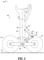
- FIGURES 1-4 illustrate a first representative embodiment of a landing gear 100 in accordance with the present disclosure.
- the landing gear 100 includes a shock strut 102 rotatably connected to structure of an aircraft (not shown).
- rotatably coupled, mounted, connected, etc. indicates that the referenced components are associated in such a way that rotational movement of one component relative to the other component is provided.
- this rotation is about an axis of rotation that has a fixed position relative to the two components, however, embodiments in which the axis of rotation is moveable relative to one or both components are possible.
- the connection of the components may allow for relative rotational movement between the components that is about a point rather than about an axis of rotation, i.e., the components pivot relative to each other.
- An actuation system (not shown) is connected to the shock strut 102 to reciprocate the shock strut, and thus the landing gear, between a gear-up, i.e., stowed, position, employed during flight, and a gear-down, i.e., deployed, position, used during takeoff ( FIGURE 2 ), landing ( FIGURE 2 ), and ground operations ( FIGURE 1 ).
- the shock strut 102 includes a cylinder 104 and a rod 106, a portion of which is slidably disposed within the cylinder along centerline 300. That is, the cylinder 104 and the rod 106 share a common centerline 300, with the rod extending from the cylinder.
- the interior wall of the cylinder 104 engages the outer surface of the rod 106 to restrict translational movement of the rod relative to the cylinder in all directions except along the centerline 300.
- the rod 106 is capable of sliding translational movement relative to the cylinder 104 along the direction of the centerline 300.
- the cylinder 104 and rod 106 cooperate to act as a shock absorber.
- the landing gear 100 also includes a truck beam 108 that is rotatably coupled to a lower end of the rod 106 about an axis 302.
- a plurality of wheels 110 are rotatably attached to the each end of the truck beam 108.
- the landing gear 100 further includes a link assembly 120 connecting the cylinder 104 to the truck beam 108.
- the link assembly 120 acts as a truck beam positioner that ensures the truck beam 108 and wheels 110 maintain a predetermined position relative to the shock strut 102 when the aircraft is airborne and, in particular, in a gear-down condition.
- the link assembly 120 includes an elongate upper link 122 rotatably coupled at an upper end to the cylinder 104 about an axis 304, and an elongate lower link 124 rotatably coupled at a lower end to the truck beam 108 about an axis 306.
- the lower end of the upper link 122 is rotatably coupled to the upper end of the lower link 124 by a limiter joint 130 about an axis 308.
- Axes 304, 306, and 308 are generally horizontal and parallel to each other.
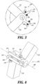
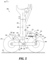
- the limiter joint 130 includes a first stop 132 associated with the upper link 122 and a second stop 140 associated with the lower link 124.
- the first stop 132 is formed by a first tab 134 that extends outwardly in a radial direction from the upper link 122 and a first contact fitting 136 extending through the first tab toward the second stop 140.
- the second stop 140 is similarly formed, having a second tab 142 that extends outwardly in a radial direction from the lower link 124 and a second contact fitting 144 extending through the second tab 142 toward the first stop 132.
- the first stop 132 moves toward the second stop 140.
- the first stop 132 and the second stop 140 contact each other when the angle ⁇ reaches the predetermined maximum value, at which point the contact between the stops prevents further rotation of the links 122, 124 relative to each other.
- contact between the first and second stops 132, 140 occurs when a first contact surface 138 of the first contact fitting 136 contacts the second tab 142 and a second contact surface 146 of the second contact fitting 144 contacts the first tab 134.
- the contact fittings 136 and 144 may include threaded bodies. The threaded engagement of the contact fittings with their respective tabs provides for adjustment of the position of the contact surfaces relative to their respective tabs by rotating the contact fittings. This adjustability allows for selective adjustment of the angle ⁇ between the upper and lower links 122, 144 achieved when the first and second stops 132, 140 contact each other. This adjustability also enables an operator to ensure that both contact surfaces 138, 146 are in contact with the opposing tab 134, 142 when the upper link 122 and lower link 124 are at the maximum predetermined angle ⁇ relative to each other.
- the contact fittings are a pair of threaded fasteners. It will be appreciated that variations in the number and location of the contact fittings are possible. Further, alternate embodiments that utilize alternate structure to limit the maximum angle between the upper link 122 and lower link 124 are possible, and such alternatives may be adjustable or fixed. In this regard, any suitable configuration that limits the maximum angle between the upper link 122 and lower link 124 may be utilized, and such configurations should be considered within the scope of the present disclosure.
- the wheels 110 are in contact with the ground 90, which establishes the position of the truck beam 108.
- the weight of the airplane compresses the shock strut 102 so that the rod 106 is in a retracted position relative to the cylinder 104.
- the link assembly 120 acts as a typical torque link to restrict rotation of the truck beam 108 and, thus, the wheels 110 and rod 106, relative to the cylinder 104 about axis 300.
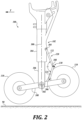
- FIGURE 2 shows the aircraft airborne and traveling in the direction of arrow T, with the landing gear 100 in a gear-down position.
- the weight of the aircraft off of the shock strut 102 the weight of the truck beam 108 and wheels 110, as well as the energy stored in the shock strut 102, cause the rod 106 to move downward relative to the cylinder 104 into an extended position.
- the angle ⁇ between the upper link 122 and the lower link 124 increases as a result of the increase in the distance between axis 304, which remains fixed relative to the cylinder 104, and axis 306, which moves downward with the truck beam 108.
- the angle ⁇ increases until it reaches a predetermined maximum value, at which point the limiter joint 130 prevents further rotation of the upper link 122 and the lower link 124 relative to each other.
- This effectively fixes the maximum length of the link assembly 120, i.e., the distance between axis 304 and axis 306. With this length effectively fixed, further downward extension of the rod 106 causes the truck beam 108 to rotate into a "toe down" position, in which the forward end of the truck beam 108 is lower than the aft end of the truck beam 108.
- the link assembly 120 positions the truck beam 108 relative to the shock strut 102 so that the landing gear 100 can be received within the landing gear bay of the aircraft.
- Aerodynamic loads act on the wheels 110 of the landing gear to bias the forward end of the truck beam 108 counter-clockwise as viewed in FIGURES 1 and 2 , biasing the landing gear 100 toward the toe down position. These loads help to maintain the truck beam 108 in the airborne deployed position (1) when the aircraft is landing but the wheels have not yet touched down, and (2) as the landing gear retracts into the landing gear bay.
- FIGURES 1 and 2 show a landing gear 100 with a toe down configuration and with the airplane traveling from right to left.
- the link assembly 120 is located aft of the shock strut 102.
- landing gear bay limitations and landing gear configurations make it necessary for the landing gear to have a "toe up" configuration in which the truck beam 108 is angled relative to the shock strut 102 so that the forward end of the truck beam is higher than the aft end.
- Such a configuration is possible with the present landing gear configuration by repositioning the link assembly 120 to be located forward of the shock strut 102, i.e., a mirror image of the link assembly positioning shown in FIGURES 1 and 2 .
- FIGURES 5 and 6 a second representative embodiment of a landing gear 200 according to the present disclosure will be described.
- a reference number indicated by 1XX or 3XX in FIGURES 1 and 2 corresponds to a reference number 2XX or 4XX, respectively, in FIGURES 5 and 6 .
- the shock strut 102 and the axis 300 shown in FIGURES 1 and 2 correspond to the shock strut 202 and the axis 400, respectively, shown in FIGURES 5 and 6 .
- the landing gear 200 includes a link assembly 220 positioned aft of the shock strut 202.
- An elongate upper link 222 of the link assembly 220 is rotatably coupled at an upper end to the cylinder 204 about an axis 404, and an elongate lower link 224 of the link assembly 220 is rotatably coupled at a lower end to the truck beam 208 about an axis 406.
- the lower end of the upper link 222 is rotatably coupled to the upper end of the lower link 224 by a limiter joint 230 about an axis 408.
- biasing element 248 biases the link assembly 220 toward the maximum effective length, i.e. towards the position in which the angle ⁇ is its maximum value as determined by the limiter joint 230. That is, the biasing element urges the axis 408 toward the shock strut 202.
- the biasing element is a tension spring 248 coupled at one end to a lug 250 on the lower link 224 of the link assembly 220. A second end of the spring 248 is coupled to a lug 252 on the shock strut 202.
- the illustrated biasing element 248 is shown as a tension spring, it will be appreciated that any number of configurations may be employed to urge the axis 408 toward the shock strut 202.
- the biasing element is a torsion spring that biases the upper link 222 to rotate relative to the shock strut 202 about axis 404 or the lower link 224 relative to the truck beam 208 about axis 406. Additional, embodiments are also contemplated in which multiple biasing elements are utilized, such as various combinations of one or more tension springs and/or torsion springs. These and other configurations to urge axis 408 toward the shock strut 202 are contemplated and should be considered within the scope of the present disclosure.
- a torque link assembly 500 can be provided and is positioned forward of the shock strut 202.
- the torque link assembly 500 includes an elongate upper torque link 502 rotatably coupled at an upper end to cylinder 204 about an axis 410 and an elongate lower torque link 504 rotatably coupled at lower end to a truck beam fitting 212 about an axis 412.
- the lower end of the upper torque link 502 is rotatably coupled to the upper end of the lower torque link about an axis 414.
- the truck beam fitting 212 is fixedly coupled to the rod 206 and rotatably coupled to the truck beam 208 about axis 402.
- axes 410, 412, and 414 are generally parallel, allowing the torque link assembly 500 to move in a scissoring motion to accommodate movement of the rod 206 as the rod extends from and retracts into the cylinder 204. At the same time, the torque link assembly 500 prevents rotation of the rod 206, and therefore the truck beam 208, about axis 400 relative to the cylinder 204.
- the inclusion of the torque link assembly 500 on the forward side of the shock strut 202 allows for a more lightweight and compact link assembly 220 on the aft side of the shock strut. Because the torque link assembly 500 reacts most of the forces tending to rotate the rod 206 and truck beam 208 about axis 400, the link assembly 220 can be sized and configured mainly for maintaining the orientation of the truck beam 208 when the aircraft is airborne. It will be further appreciated that alternate embodiments are possible in which the torque link assembly 500 is omitted, similar to the embodiment of FIGURES 1-4 , so that the link assembly 220 maintains the orientation of the truck beam 208 while also preventing rotation of the rod 206 about axis 400.
- FIGURE 6 when the aircraft is airborne and traveling in the direction of arrow T with the landing gear 200 in a gear-down position, the shock strut 202 is in an extended position.
- the link assembly 220 and the associated limiter joint 230 operate to position the truck beam in a toe down position, similar to the embodiment of FIGURES 1-4 .
- the embodiment of FIGURES 5 and 6 uses the biasing element 248 in addition to the aerodynamic loads acting on the wheels 110 to bias the forward end of the truck beam 208 counter-clockwise as viewed in FIGURES 5 and 6 , thereby biasing the landing gear 100 toward the toe down position.
- the landing gear 200 shown in FIGURES 5 and 6 can be configured to provide a toe up position by positioning the link assembly 220 forward of the shock strut 202 and the torque link assembly 500 aft of the shock strut.
- the present application may also reference quantities and numbers. Unless specifically stated, such quantities and numbers are not to be considered restrictive, but exemplary of the possible quantities or numbers associated with the present application. Also in this regard, the present application may use the term “plurality” to reference a quantity or number. In this regard, the term “plurality” is meant to be any number that is more than one, for example, two, three, four, five, etc. The terms “about,” “approximately,” “near,” etc., mean plus or minus 5% of the stated value.
- the phrase "at least one of A, B, and C,” for example, means (A), (B), (C), (A and B), (A and C), (B and C), or (A, B, and C), including all further possible permutations when greater than three elements are listed.
Landscapes
- Engineering & Computer Science (AREA)
- Mechanical Engineering (AREA)
- Aviation & Aerospace Engineering (AREA)
- Transmission Devices (AREA)
- Vibration Dampers (AREA)
Description
- In order to accommodate nose-up rotation during takeoff, long-body aircraft require tall main landing gear to prevent the tail from impacting the ground. A common configuration utilizes a truck beam mounted to the aircraft fuselage by an elongate shock strut. Multiple wheels are mounted to the truck beam, which is rotatable relative to the shock strut to enable the wheels to maintain contact with the ground while the aircraft initially rotates during takeoff.
- During landing, the truck beam is typically maintained in a predetermined "toe up" or "toe down" position just prior to touchdown. Touchdown is detected by sensors that sense rotation of the truck beam that occurs subsequent to the first wheel contacting the ground. That is, after the first wheel makes contact, the truck beam rotates into a generally horizontal position in which all of the wheels are in contact with the ground. It is also necessary to maintain the truck beam in the predetermined position when the aircraft is airborne to ensure that the main landing gear will fit within the landing gear bay when the gear is retracted.
- Known truck beam positioners include active positioners, which utilize various types of actuators to control the position of the truck beam.
U.S. Patent No. 8,382,032 discloses one such active truck beam positioner, wherein an auxiliary actuator is connected to the landing gear strut and the truck beam. The auxiliary actuator is hydraulically energized to selectively change length, thereby controlling the angle of the truck beam relative to the strut. - Other truck beam positioner configurations are passive positioners, which rely on biasing elements, such as springs, and/or aerodynamic loads to position the truck beam. A passive positioner is disclosed in
U.S. Patent No. 4,892,270 . The position of the truck beam is maintained by a spring loaded-telescopic link in combination with limiter incorporated in the torque link. The telescopic link extends between the shock strut and the truck beam and urges the forward end of the truck beam to rotate downward. At the same time, the limiter includes an abutment that bears against the shock strut to limit the downward rotation of the truck beam to lock the torque link and the landing gear in a bottom limit position. - Known passive and active truck beam positioners add weight, cost, complexity, and maintenance requirements to the aircraft.
-
US 3652040A discloses that a wheel-supporting piston of the strut is rotated relative to the cylinder by an adjustable torque arm interconnection of the two to eliminate vertical friction, the adjustment being made by a hydraulic actuator, and a pressure readout of the internal strut pressure provides indication of the vertical weight load on the gear after such friction elimination. -
US4720063A discloses a hydraulic control cylinder used to swing the upper part of a two part wheel strut about an axis of rotation established at the upper end of the upper strut part and at an upper central location within a stowage compartment. A folding drag brace assembly is connected between the strut and a lower rear portion of the stowage compartment. During use of the control cylinder for swinging the upper strut part rearwardly and upwardly, the drag brace folds automatically in the manner of a pantographic device, and functions to fold the lower strut part up against the upper strut part within the stowage compartment. A mechanism is provided for rotating the wheel assembly W, relative to the lower strut part, for the purpose of properly positioning the wheel assembly W for movement into the stowage compartment. -
US2011/233327 discloses a semi-levered landing gear that includes a shock strut, a truck beam pivotally connected to the shock strut and a semi-levered landing gear mechanism including at least three links configured to angularly orient the truck beam and a truck pitch actuation system operatively connected to at least one of the three links. The landing gear mechanism may be configured to cooperate with an extension of a shock strut by positioning the truck pitch actuator in a retracted position, thereby positioning a forward end of the truck beam in a raised position relative to the aft end of the truck beam. The landing gear mechanism may also be configured to cooperate with a retraction of the shock strut into the wheel well by extending the truck pitch actuator to position a forward end of the truck beam in a lower position relative to the aft end of the truck beam. - The disclosed technology relates to landing gear that utilizes a simplified, lightweight passive truck beam positioner that reduces cost, weight, and maintenance, while also increasing reliability as compared known positioning systems. The disclosed aircraft landing gear includes a shock strut having a rod with a first end slidably disposed within a cylinder. A beam is rotatably coupled to a second end of the rod. The beam is configured to have at least a forward wheel and an aft wheel rotatably mounted thereto. The landing gear further includes a link assembly that has an upper link and a lower link. The upper link has a first end rotatably connected to the cylinder, and the lower link has a first end rotatably connected to the beam. The second end of the lower link is rotatably coupled to the second end of the upper link by a limiter joint. The limiter joint includes a first stop associated the upper link and a second stop associated with the lower link. The stops are configured such that the first stop engages the second stop to limit rotation of the upper link relative to the lower link.
- The limiter is selectively adjustable to provide a predetermined maximum distance between the first end of the upper link and the first end of the lower link.
- In an embodiment, the first stop comprises a first tab extending from the first leg, and the second stop comprises a second tab extending from the second leg.
- In another embodiment, the first stop further comprises a first contact fitting coupled to the first tab, the first contact fitting having a first contact surface configured to contact the second stop, wherein a position of the first contact surface is selectively adjustable relative to the first tab.
- In another embodiment, the first contact fitting is a first threaded fastener threadedly coupled to the first tab.
- In another embodiment, the second stop further comprises a second contact fitting coupled to the second tab, the second contact fitting having a second contact surface configured to contact the first stop, wherein the position of the second contact surface is selectively adjustable relative to the second tab.
- In another embodiment, the second contact fitting is a second threaded fastener threadedly coupled to the second tab.
- In another embodiment, the second stop further comprises a second contact fitting coupled to the second tab, the second contact fitting having a second contact surface configured to contact the first stop, wherein a position of the second contact surface is selectively adjustable relative to the second tab.
- In another embodiment, a torque link assembly is positioned on one of a leading (forward) edge and trailing (aft) edge of the shock strut. The torque link assembly includes an upper torque link with a first end rotatably coupled to the cylinder and a lower torque link with a first end rotatable coupled to the rod. The second end of the lower torque link is rotatably coupled to the second end of the upper torque link. The link assembly is positioned on the other of the leading edge and the trailing edge of the shock strut.
- In another embodiment, the link assembly is located forward of the shock strut.
- In another embodiment, the torque link assembly is positioned aft of the shock strut.
- In another embodiment, the biasing element comprises a tension spring having a first end coupled to the cylinder and a second end coupled to the lower link of the truck beam positioner.
- This summary is provided to introduce a selection of concepts in a simplified form that are further described below in the Detailed Description.
- The foregoing aspects and many of the attendant advantages of the disclosed subject matter will become more readily appreciated as the same become better understood by reference to the following detailed description, when taken in conjunction with the accompanying drawings, wherein:
-
FIGURE 1 is a side view of a first representative embodiment of a landing gear for an aircraft according to the present disclosure, wherein the aircraft is on the ground; -
FIGURE 2 is a side view of the landing gear shown inFIGURE 2 , wherein the aircraft is in a takeoff or landing condition; -
FIGURE 3 is a detailed view of one representative embodiment of a limiter joint of the landing gear shown inFIGURE 1 ; -
FIGURE 4 is an isometric view of the limiter joint shown inFIGURE 3 ; -
FIGURE 5 is a side view of a second representative embodiment of a landing gear for an aircraft according to the present disclosure, wherein the aircraft is on the ground; and -
FIGURE 6 is a side view of the landing gear shown inFIGURE 5 , wherein the aircraft is in a takeoff or landing condition. -
FIGURES 1-4 illustrate a first representative embodiment of alanding gear 100 in accordance with the present disclosure. Thelanding gear 100 includes ashock strut 102 rotatably connected to structure of an aircraft (not shown). - As used herein, "rotatably" coupled, mounted, connected, etc., indicates that the referenced components are associated in such a way that rotational movement of one component relative to the other component is provided. Typically this rotation is about an axis of rotation that has a fixed position relative to the two components, however, embodiments in which the axis of rotation is moveable relative to one or both components are possible. It will also be appreciated that in some contemplated embodiments, the connection of the components may allow for relative rotational movement between the components that is about a point rather than about an axis of rotation, i.e., the components pivot relative to each other.
- An actuation system (not shown) is connected to the
shock strut 102 to reciprocate the shock strut, and thus the landing gear, between a gear-up, i.e., stowed, position, employed during flight, and a gear-down, i.e., deployed, position, used during takeoff (FIGURE 2 ), landing (FIGURE 2 ), and ground operations (FIGURE 1 ). - As best shown in
FIGURES 1 and2 , theshock strut 102 includes acylinder 104 and arod 106, a portion of which is slidably disposed within the cylinder alongcenterline 300. That is, thecylinder 104 and therod 106 share acommon centerline 300, with the rod extending from the cylinder. The interior wall of thecylinder 104 engages the outer surface of therod 106 to restrict translational movement of the rod relative to the cylinder in all directions except along thecenterline 300. As a result, therod 106 is capable of sliding translational movement relative to thecylinder 104 along the direction of thecenterline 300. Thecylinder 104 androd 106 cooperate to act as a shock absorber. - The
landing gear 100 also includes atruck beam 108 that is rotatably coupled to a lower end of therod 106 about anaxis 302. A plurality ofwheels 110 are rotatably attached to the each end of thetruck beam 108. - The
landing gear 100 further includes alink assembly 120 connecting thecylinder 104 to thetruck beam 108. As will be described in further detail, thelink assembly 120 acts as a truck beam positioner that ensures thetruck beam 108 andwheels 110 maintain a predetermined position relative to theshock strut 102 when the aircraft is airborne and, in particular, in a gear-down condition. - The
link assembly 120 includes an elongateupper link 122 rotatably coupled at an upper end to thecylinder 104 about anaxis 304, and an elongatelower link 124 rotatably coupled at a lower end to thetruck beam 108 about anaxis 306. In the embodiment shown, the lower end of theupper link 122 is rotatably coupled to the upper end of thelower link 124 by a limiter joint 130 about anaxis 308.Axes rod 102 moves out of thecylinder 104, thelink assembly 120 moves in a scissoring motion so that an angle α between theupper link 122 andlower link 124 increases. Similarly, the angle α decreases as therod 106 moves further into thecylinder 104. - Referring now to
FIGURES 3 and 4 , the limiter joint 130 will be described in more detail. As shown inFIGURES 3 and 4 , the limiter joint 130 includes afirst stop 132 associated with theupper link 122 and asecond stop 140 associated with thelower link 124. In the embodiment shown, thefirst stop 132 is formed by afirst tab 134 that extends outwardly in a radial direction from theupper link 122 and a first contact fitting 136 extending through the first tab toward thesecond stop 140. Thesecond stop 140 is similarly formed, having asecond tab 142 that extends outwardly in a radial direction from thelower link 124 and a second contact fitting 144 extending through thesecond tab 142 toward thefirst stop 132. - As the
upper link 122 and thelower link 124 rotate relative to each other aboutaxis 308 such that the angle α increases, thefirst stop 132 moves toward thesecond stop 140. In this regard, thefirst stop 132 and thesecond stop 140 contact each other when the angle α reaches the predetermined maximum value, at which point the contact between the stops prevents further rotation of thelinks - In the illustrated embodiment, contact between the first and
second stops first contact surface 138 of the first contact fitting 136 contacts thesecond tab 142 and asecond contact surface 146 of the second contact fitting 144 contacts thefirst tab 134. In some embodiments, thecontact fittings lower links second stops tab upper link 122 andlower link 124 are at the maximum predetermined angle α relative to each other. - In the illustrated embodiment, the contact fittings are a pair of threaded fasteners. It will be appreciated that variations in the number and location of the contact fittings are possible. Further, alternate embodiments that utilize alternate structure to limit the maximum angle between the
upper link 122 andlower link 124 are possible, and such alternatives may be adjustable or fixed. In this regard, any suitable configuration that limits the maximum angle between theupper link 122 andlower link 124 may be utilized, and such configurations should be considered within the scope of the present disclosure. - Referring back to
FIGURE 1 , when the aircraft is on the ground, thewheels 110 are in contact with theground 90, which establishes the position of thetruck beam 108. The weight of the airplane compresses theshock strut 102 so that therod 106 is in a retracted position relative to thecylinder 104. In this position, thelink assembly 120 acts as a typical torque link to restrict rotation of thetruck beam 108 and, thus, thewheels 110 androd 106, relative to thecylinder 104 aboutaxis 300. -
FIGURE 2 shows the aircraft airborne and traveling in the direction of arrow T, with thelanding gear 100 in a gear-down position. With the weight of the aircraft off of theshock strut 102, the weight of thetruck beam 108 andwheels 110, as well as the energy stored in theshock strut 102, cause therod 106 to move downward relative to thecylinder 104 into an extended position. As therod 106 moves toward the extended position, the angle α between theupper link 122 and thelower link 124 increases as a result of the increase in the distance betweenaxis 304, which remains fixed relative to thecylinder 104, andaxis 306, which moves downward with thetruck beam 108. The angle α increases until it reaches a predetermined maximum value, at which point the limiter joint 130 prevents further rotation of theupper link 122 and thelower link 124 relative to each other. This, in turn, effectively fixes the maximum length of thelink assembly 120, i.e., the distance betweenaxis 304 andaxis 306. With this length effectively fixed, further downward extension of therod 106 causes thetruck beam 108 to rotate into a "toe down" position, in which the forward end of thetruck beam 108 is lower than the aft end of thetruck beam 108. - In the airborne gear-down position, the
link assembly 120 positions thetruck beam 108 relative to theshock strut 102 so that thelanding gear 100 can be received within the landing gear bay of the aircraft. Aerodynamic loads act on thewheels 110 of the landing gear to bias the forward end of thetruck beam 108 counter-clockwise as viewed inFIGURES 1 and2 , biasing thelanding gear 100 toward the toe down position. These loads help to maintain thetruck beam 108 in the airborne deployed position (1) when the aircraft is landing but the wheels have not yet touched down, and (2) as the landing gear retracts into the landing gear bay. - As previously noted,
FIGURES 1 and2 show alanding gear 100 with a toe down configuration and with the airplane traveling from right to left. Thus thelink assembly 120 is located aft of theshock strut 102. In some aircraft, landing gear bay limitations and landing gear configurations make it necessary for the landing gear to have a "toe up" configuration in which thetruck beam 108 is angled relative to theshock strut 102 so that the forward end of the truck beam is higher than the aft end. Such a configuration is possible with the present landing gear configuration by repositioning thelink assembly 120 to be located forward of theshock strut 102, i.e., a mirror image of the link assembly positioning shown inFIGURES 1 and2 . - Referring now to
FIGURES 5 and6 , a second representative embodiment of alanding gear 200 according to the present disclosure will be described. For the sake of brevity, unless specifically noted, previously described features of the first embodiment shown inFIGURES 1 and2 that are also present inFIGURES 5 and6 will not be described again. For such features, a reference number indicated by 1XX or 3XX inFIGURES 1 and2 corresponds to a reference number 2XX or 4XX, respectively, inFIGURES 5 and6 . For example, except as otherwise noted, theshock strut 102 and theaxis 300 shown inFIGURES 1 and2 correspond to theshock strut 202 and theaxis 400, respectively, shown inFIGURES 5 and6 . - In the illustrated embodiment, the
landing gear 200 includes alink assembly 220 positioned aft of theshock strut 202. An elongateupper link 222 of thelink assembly 220 is rotatably coupled at an upper end to thecylinder 204 about anaxis 404, and an elongatelower link 224 of thelink assembly 220 is rotatably coupled at a lower end to thetruck beam 208 about anaxis 406. The lower end of theupper link 222 is rotatably coupled to the upper end of thelower link 224 by a limiter joint 230 about anaxis 408. - In the embodiment shown, biasing
element 248 biases thelink assembly 220 toward the maximum effective length, i.e. towards the position in which the angle α is its maximum value as determined by the limiter joint 230. That is, the biasing element urges theaxis 408 toward theshock strut 202. In the illustrated embodiment, the biasing element is atension spring 248 coupled at one end to alug 250 on thelower link 224 of thelink assembly 220. A second end of thespring 248 is coupled to alug 252 on theshock strut 202. - Although the illustrated
biasing element 248 is shown as a tension spring, it will be appreciated that any number of configurations may be employed to urge theaxis 408 toward theshock strut 202. In one contemplated embodiment, the biasing element is a torsion spring that biases theupper link 222 to rotate relative to theshock strut 202 aboutaxis 404 or thelower link 224 relative to thetruck beam 208 aboutaxis 406. Additional, embodiments are also contemplated in which multiple biasing elements are utilized, such as various combinations of one or more tension springs and/or torsion springs. These and other configurations to urgeaxis 408 toward theshock strut 202 are contemplated and should be considered within the scope of the present disclosure. - Still referring to
FIGURES 5 and6 , atorque link assembly 500 can be provided and is positioned forward of theshock strut 202. Thetorque link assembly 500 includes an elongateupper torque link 502 rotatably coupled at an upper end tocylinder 204 about anaxis 410 and an elongatelower torque link 504 rotatably coupled at lower end to a truck beam fitting 212 about anaxis 412. The lower end of theupper torque link 502 is rotatably coupled to the upper end of the lower torque link about anaxis 414. The truck beam fitting 212 is fixedly coupled to therod 206 and rotatably coupled to thetruck beam 208 aboutaxis 402. - As with known torque link assemblies, axes 410, 412, and 414 are generally parallel, allowing the
torque link assembly 500 to move in a scissoring motion to accommodate movement of therod 206 as the rod extends from and retracts into thecylinder 204. At the same time, thetorque link assembly 500 prevents rotation of therod 206, and therefore thetruck beam 208, aboutaxis 400 relative to thecylinder 204. - It will be appreciated that the inclusion of the
torque link assembly 500 on the forward side of theshock strut 202 allows for a more lightweight andcompact link assembly 220 on the aft side of the shock strut. Because thetorque link assembly 500 reacts most of the forces tending to rotate therod 206 andtruck beam 208 aboutaxis 400, thelink assembly 220 can be sized and configured mainly for maintaining the orientation of thetruck beam 208 when the aircraft is airborne. It will be further appreciated that alternate embodiments are possible in which thetorque link assembly 500 is omitted, similar to the embodiment ofFIGURES 1-4 , so that thelink assembly 220 maintains the orientation of thetruck beam 208 while also preventing rotation of therod 206 aboutaxis 400. - As shown in
FIGURE 5 , when the aircraft is on the ground, theground 90 establishes the position of thetruck beam 208, and theshock strut 202 is compressed under the weight of the aircraft. Thetorque link assembly 500, and to a much lesser extent thelink assembly 220, restrict rotation of thetruck beam 208 relative to thecylinder 204 aboutaxis 400. - As shown in
FIGURE 6 , when the aircraft is airborne and traveling in the direction of arrow T with thelanding gear 200 in a gear-down position, theshock strut 202 is in an extended position. Thelink assembly 220 and the associated limiter joint 230 operate to position the truck beam in a toe down position, similar to the embodiment ofFIGURES 1-4 . However, the embodiment ofFIGURES 5 and6 uses thebiasing element 248 in addition to the aerodynamic loads acting on thewheels 110 to bias the forward end of thetruck beam 208 counter-clockwise as viewed inFIGURES 5 and6 , thereby biasing thelanding gear 100 toward the toe down position. - Similar to the embodiment of
FIGURES 1-4 , thelanding gear 200 shown inFIGURES 5 and6 can be configured to provide a toe up position by positioning thelink assembly 220 forward of theshock strut 202 and thetorque link assembly 500 aft of the shock strut. - In the description above, specific details are set forth to provide a thorough understanding of representative embodiments of the present disclosure. It will be apparent to one skilled in the art, however, that the embodiments disclosed herein may be practiced without embodying all of the specific details. In some instances, well-known process steps have not been described in detail in order not to unnecessarily obscure various aspects of the present disclosure. Further, it will be appreciated that embodiments of the present disclosure may employ any combination of features described herein.
- It should be noted that for purposes of this disclosure, terminology such as "upper," "lower," "vertical," "horizontal," "inwardly," "outwardly," "inner," "outer," "forward," "rear," etc., should be construed as descriptive and not limiting the scope of the claimed subject matter. Further, the use of "including," "comprising," or "having" and variations thereof herein is meant to encompass the items listed thereafter as well as additional items. Unless limited otherwise, the terms "connected," "coupled," and "mounted" and variations thereof herein are used broadly and encompass direct and indirect connections, couplings, and mountings.
- The present application may also reference quantities and numbers. Unless specifically stated, such quantities and numbers are not to be considered restrictive, but exemplary of the possible quantities or numbers associated with the present application. Also in this regard, the present application may use the term "plurality" to reference a quantity or number. In this regard, the term "plurality" is meant to be any number that is more than one, for example, two, three, four, five, etc. The terms "about," "approximately," "near," etc., mean plus or minus 5% of the stated value. For the purposes of the present disclosure, the phrase "at least one of A, B, and C," for example, means (A), (B), (C), (A and B), (A and C), (B and C), or (A, B, and C), including all further possible permutations when greater than three elements are listed.
- The principles, representative embodiments, and modes of operation of the present disclosure have been described in the foregoing description. However, aspects of the present disclosure which are intended to be protected are not to be construed as limited to the particular embodiments disclosed. Further, the embodiments described herein are to be regarded as illustrative rather than restrictive. Therefore, the scope of protection is intended to be limited only by the appended claims.
Claims (12)
- An aircraft landing gear (100), comprising:a shock strut (102) including a rod (106) with a first end slidably disposed within a cylinder (104);a beam (108) rotatably coupled to a second end of the rod, the beam being configured to have a forward wheel and an aft wheel rotatably mounted thereto; anda link assembly (120), comprising:
an upper link (122) having a first end rotatably connected to the cylinder(104); anda lower link (124) having a first end rotatably connected to the beam, a second end of the lower link (124) being rotatably coupled to a second end of the upper link (122); anda limiter (130),characterised in thatthe limiter comprises a first stop (132) associated with the upper link and a second stop (140) associated with the lower link, the first stop engaging the second stop to limit rotation of the upper link relative to the lower link, wherein the limiter is selectively adjustable to provide a predetermined maximum distance between the first end of the upper link and the first end of the lower link. - The landing gear of Claim 1, wherein the first stop (132) comprises a first tab (134) extending from the upper link, and the second stop (140) comprises a second tab (142) extending from the lower link.
- The landing gear of Claim 2, wherein the first stop (132) further comprises a first contact fitting (136) coupled to the first tab, the first contact fitting (136) having a first contact surface (138) configured to contact the second stop (140), wherein a position of the first contact surface (138) is selectively adjustable relative to the first tab.
- The landing gear of Claim 3, wherein the first contact fitting (136) is a first threaded fastener threadedly coupled to the first tab (134).
- The landing gear of any one of Claims 3, 4 wherein the second stop (140) further comprises a second contact fitting (144) coupled to the second tab (142), the second contact fitting (144) having a second contact surface (146) configured to contact the first stop (132), wherein the position of the second contact surface (146) is selectively adjustable relative to the second tab (142).
- The landing gear of Claim 5, wherein the second contact fitting (144) is a second threaded fastener threadedly coupled to the second tab (142).
- The landing gear of any one of Claims 1-6, further comprising a biasing element (248) coupled to the link assembly (120) and configured to urge the second end of the lower link toward the shock strut (102).
- The landing gear of any one of Claims 1-7, wherein the link assembly (120) is positioned aft of the shock strut.
- The aircraft landing gear (100) according to claim 1, said aircraft landing gear (100) further comprising:
a torque link assembly (500) located on one of forward and aft of the shock strut (202), the link assembly (220) being located on the other of forward and aft of the shock strut (202),the torque link assembly (500) comprising:an upper torque link having a first end rotatably coupled to the cylinder; anda lower torque link having a first end rotatably coupled to the rod and a second end rotatably coupled to a second end of the upper torque link; andthe aircraft landing gear further comprising
a spring (248) coupled to one of the upper and lower links and configured to bias the second end of the lower link toward the shock strut (202). - The landing gear of Claim 9, wherein the link assembly (220) is located forward of the shock strut (202).
- The landing gear of Claim 9 or Claim 10, wherein the torque link assembly (500) is positioned aft of the shock strut (202).
- The landing gear of any one of Claims 9-11, wherein the spring is a tension spring having a first end coupled to the cylinder and a second end coupled to the lower link of the link assembly (220).
Applications Claiming Priority (2)
| Application Number | Priority Date | Filing Date | Title |
|---|---|---|---|
| US16/526,645 US11091252B2 (en) | 2019-07-30 | 2019-07-30 | Aircraft multi-wheel truck beam positioner |
| PCT/CA2020/051034 WO2021016706A1 (en) | 2019-07-30 | 2020-07-28 | Aircraft multi-wheel truck beam positioner |
Publications (3)
| Publication Number | Publication Date |
|---|---|
| EP4003833A1 EP4003833A1 (en) | 2022-06-01 |
| EP4003833A4 EP4003833A4 (en) | 2023-08-02 |
| EP4003833B1 true EP4003833B1 (en) | 2025-06-04 |
Family
ID=74229364
Family Applications (1)
| Application Number | Title | Priority Date | Filing Date |
|---|---|---|---|
| EP20847660.6A Active EP4003833B1 (en) | 2019-07-30 | 2020-07-28 | Aircraft multi-wheel truck beam positioner |
Country Status (5)
| Country | Link |
|---|---|
| US (1) | US11091252B2 (en) |
| EP (1) | EP4003833B1 (en) |
| CN (1) | CN114340995B (en) |
| CA (1) | CA3146975A1 (en) |
| WO (1) | WO2021016706A1 (en) |
Families Citing this family (2)
| Publication number | Priority date | Publication date | Assignee | Title |
|---|---|---|---|---|
| US11892052B2 (en) * | 2022-05-06 | 2024-02-06 | Goodrich Corporation | Temperature compensated shock strut visual health indicator systems and methods |
| US12054282B2 (en) * | 2022-05-23 | 2024-08-06 | Safran Landing Systems Canada Inc. | Landing gear load detection system |
Family Cites Families (12)
| Publication number | Priority date | Publication date | Assignee | Title |
|---|---|---|---|---|
| US3652040A (en) * | 1970-06-10 | 1972-03-28 | Cleveland Pneumatic Tool Co | Landing gear shock strut |
| US4359199A (en) * | 1979-12-05 | 1982-11-16 | The United States Of America As Represented By The Secretary Of The Air Force | Soft landing gear |
| US4720063A (en) * | 1985-09-30 | 1988-01-19 | The Boeing Company | Main landing gear with variable length drag brace |
| FR2616410B1 (en) * | 1987-06-09 | 1992-08-21 | Messier Hispano Sa | TIPPING BEAM LANDING DEVICE |
| WO2006094145A1 (en) | 2005-03-02 | 2006-09-08 | Goodrich Corporation | Landing gear with articulated length extension mechanism |
| GB2428650B (en) * | 2005-08-04 | 2011-01-12 | Messier Dowty Ltd | Landing gear |
| US8448900B2 (en) | 2010-03-24 | 2013-05-28 | The Boeing Company | Semi-levered landing gear and associated method |
| US8939400B2 (en) * | 2011-02-21 | 2015-01-27 | The Boeing Company | Air-ground detection system for semi-levered landing gear |
| GB2489058B (en) * | 2011-08-22 | 2013-05-08 | Messier Dowty Ltd | Aircraft landing gear |
| GB2501906A (en) * | 2012-05-10 | 2013-11-13 | Ge Aviat Systems Ltd | Aircraft landing gear |
| CN205396520U (en) * | 2015-12-31 | 2016-07-27 | 零度智控(北京)智能科技有限公司 | Undercarriage installation component , undercarriage subassembly and aircraft |
| GB2563946A (en) * | 2017-06-30 | 2019-01-02 | Airbus Operations Ltd | Pitch trimmer |
-
2019
- 2019-07-30 US US16/526,645 patent/US11091252B2/en active Active
-
2020
- 2020-07-28 EP EP20847660.6A patent/EP4003833B1/en active Active
- 2020-07-28 WO PCT/CA2020/051034 patent/WO2021016706A1/en not_active Ceased
- 2020-07-28 CN CN202080054599.0A patent/CN114340995B/en active Active
- 2020-07-28 CA CA3146975A patent/CA3146975A1/en active Pending
Also Published As
| Publication number | Publication date |
|---|---|
| CN114340995A (en) | 2022-04-12 |
| CA3146975A1 (en) | 2021-02-04 |
| WO2021016706A1 (en) | 2021-02-04 |
| EP4003833A1 (en) | 2022-06-01 |
| CN114340995B (en) | 2025-11-18 |
| US11091252B2 (en) | 2021-08-17 |
| EP4003833A4 (en) | 2023-08-02 |
| US20210031906A1 (en) | 2021-02-04 |
Similar Documents
| Publication | Publication Date | Title |
|---|---|---|
| AU2011229883B2 (en) | Semi-levered landing gear and associated method | |
| EP1041001B1 (en) | Semi-levered landing gear and auxiliary strut therefor | |
| US7731124B2 (en) | Landing gear | |
| EP2455283B1 (en) | Hydraulic actuator for semi levered landing gear | |
| US8186620B2 (en) | Adjustable landing gear system | |
| US8038096B2 (en) | Aircraft landing gear assembly | |
| EP3135582B1 (en) | Three-position aircraft tail skid mechanism and method of actuation | |
| EP3335988B1 (en) | Non-jamming shrink latch assembly for retractable aircraft landing gear | |
| US20160144952A1 (en) | Vertically retracting side articulating landing gear for aircraft | |
| US9650128B2 (en) | Aircraft landing gear | |
| EP2748063B1 (en) | Aircraft landing gear | |
| US11014654B2 (en) | Pitch trimmer | |
| EP3498601B1 (en) | Latch assembly for shock strut | |
| US20170158315A1 (en) | System and method for spring assisted landing gear operation | |
| EP2937281B1 (en) | Bogie beam articulation mechanism | |
| WO2006094145A9 (en) | Landing gear with articulated length extension mechanism | |
| US11091252B2 (en) | Aircraft multi-wheel truck beam positioner | |
| US6349901B1 (en) | Landing gear | |
| EP3862263B1 (en) | Articulating truss configuration for aircraft landing gear |
Legal Events
| Date | Code | Title | Description |
|---|---|---|---|
| STAA | Information on the status of an ep patent application or granted ep patent |
Free format text: STATUS: THE INTERNATIONAL PUBLICATION HAS BEEN MADE |
|
| PUAI | Public reference made under article 153(3) epc to a published international application that has entered the european phase |
Free format text: ORIGINAL CODE: 0009012 |
|
| STAA | Information on the status of an ep patent application or granted ep patent |
Free format text: STATUS: REQUEST FOR EXAMINATION WAS MADE |
|
| 17P | Request for examination filed |
Effective date: 20220218 |
|
| AK | Designated contracting states |
Kind code of ref document: A1 Designated state(s): AL AT BE BG CH CY CZ DE DK EE ES FI FR GB GR HR HU IE IS IT LI LT LU LV MC MK MT NL NO PL PT RO RS SE SI SK SM TR |
|
| DAV | Request for validation of the european patent (deleted) | ||
| DAX | Request for extension of the european patent (deleted) | ||
| REG | Reference to a national code |
Ipc: B64C0025600000 Ref country code: DE Ref legal event code: R079 Ref document number: 602020052412 Country of ref document: DE Free format text: PREVIOUS MAIN CLASS: B64C0025360000 Ipc: B64C0025600000 |
|
| A4 | Supplementary search report drawn up and despatched |
Effective date: 20230629 |
|
| RIC1 | Information provided on ipc code assigned before grant |
Ipc: B64C 25/34 20060101ALI20230623BHEP Ipc: B64C 25/60 20060101AFI20230623BHEP |
|
| GRAP | Despatch of communication of intention to grant a patent |
Free format text: ORIGINAL CODE: EPIDOSNIGR1 |
|
| STAA | Information on the status of an ep patent application or granted ep patent |
Free format text: STATUS: GRANT OF PATENT IS INTENDED |
|
| INTG | Intention to grant announced |
Effective date: 20250102 |
|
| GRAS | Grant fee paid |
Free format text: ORIGINAL CODE: EPIDOSNIGR3 |
|
| GRAA | (expected) grant |
Free format text: ORIGINAL CODE: 0009210 |
|
| STAA | Information on the status of an ep patent application or granted ep patent |
Free format text: STATUS: THE PATENT HAS BEEN GRANTED |
|
| AK | Designated contracting states |
Kind code of ref document: B1 Designated state(s): AL AT BE BG CH CY CZ DE DK EE ES FI FR GB GR HR HU IE IS IT LI LT LU LV MC MK MT NL NO PL PT RO RS SE SI SK SM TR |
|
| REG | Reference to a national code |
Ref country code: GB Ref legal event code: FG4D |
|
| REG | Reference to a national code |
Ref country code: CH Ref legal event code: EP |
|
| REG | Reference to a national code |
Ref country code: DE Ref legal event code: R096 Ref document number: 602020052412 Country of ref document: DE |
|
| REG | Reference to a national code |
Ref country code: IE Ref legal event code: FG4D |
|
| REG | Reference to a national code |
Ref country code: NL Ref legal event code: MP Effective date: 20250604 |
|
| PG25 | Lapsed in a contracting state [announced via postgrant information from national office to epo] |
Ref country code: FI Free format text: LAPSE BECAUSE OF FAILURE TO SUBMIT A TRANSLATION OF THE DESCRIPTION OR TO PAY THE FEE WITHIN THE PRESCRIBED TIME-LIMIT Effective date: 20250604 Ref country code: ES Free format text: LAPSE BECAUSE OF FAILURE TO SUBMIT A TRANSLATION OF THE DESCRIPTION OR TO PAY THE FEE WITHIN THE PRESCRIBED TIME-LIMIT Effective date: 20250604 |
|
| PGFP | Annual fee paid to national office [announced via postgrant information from national office to epo] |
Ref country code: DE Payment date: 20250730 Year of fee payment: 6 |
|
| REG | Reference to a national code |
Ref country code: LT Ref legal event code: MG9D |
|
| PG25 | Lapsed in a contracting state [announced via postgrant information from national office to epo] |
Ref country code: NO Free format text: LAPSE BECAUSE OF FAILURE TO SUBMIT A TRANSLATION OF THE DESCRIPTION OR TO PAY THE FEE WITHIN THE PRESCRIBED TIME-LIMIT Effective date: 20250904 Ref country code: GR Free format text: LAPSE BECAUSE OF FAILURE TO SUBMIT A TRANSLATION OF THE DESCRIPTION OR TO PAY THE FEE WITHIN THE PRESCRIBED TIME-LIMIT Effective date: 20250905 |
|
| PG25 | Lapsed in a contracting state [announced via postgrant information from national office to epo] |
Ref country code: PL Free format text: LAPSE BECAUSE OF FAILURE TO SUBMIT A TRANSLATION OF THE DESCRIPTION OR TO PAY THE FEE WITHIN THE PRESCRIBED TIME-LIMIT Effective date: 20250604 |
|
| PG25 | Lapsed in a contracting state [announced via postgrant information from national office to epo] |
Ref country code: BG Free format text: LAPSE BECAUSE OF FAILURE TO SUBMIT A TRANSLATION OF THE DESCRIPTION OR TO PAY THE FEE WITHIN THE PRESCRIBED TIME-LIMIT Effective date: 20250604 |
|
| PGFP | Annual fee paid to national office [announced via postgrant information from national office to epo] |
Ref country code: GB Payment date: 20250730 Year of fee payment: 6 |
|
| PG25 | Lapsed in a contracting state [announced via postgrant information from national office to epo] |
Ref country code: HR Free format text: LAPSE BECAUSE OF FAILURE TO SUBMIT A TRANSLATION OF THE DESCRIPTION OR TO PAY THE FEE WITHIN THE PRESCRIBED TIME-LIMIT Effective date: 20250604 |
|
| PGFP | Annual fee paid to national office [announced via postgrant information from national office to epo] |
Ref country code: FR Payment date: 20250730 Year of fee payment: 6 |
|
| PG25 | Lapsed in a contracting state [announced via postgrant information from national office to epo] |
Ref country code: RS Free format text: LAPSE BECAUSE OF FAILURE TO SUBMIT A TRANSLATION OF THE DESCRIPTION OR TO PAY THE FEE WITHIN THE PRESCRIBED TIME-LIMIT Effective date: 20250904 |
|
| PG25 | Lapsed in a contracting state [announced via postgrant information from national office to epo] |
Ref country code: LV Free format text: LAPSE BECAUSE OF FAILURE TO SUBMIT A TRANSLATION OF THE DESCRIPTION OR TO PAY THE FEE WITHIN THE PRESCRIBED TIME-LIMIT Effective date: 20250604 |
|
| PG25 | Lapsed in a contracting state [announced via postgrant information from national office to epo] |
Ref country code: NL Free format text: LAPSE BECAUSE OF FAILURE TO SUBMIT A TRANSLATION OF THE DESCRIPTION OR TO PAY THE FEE WITHIN THE PRESCRIBED TIME-LIMIT Effective date: 20250604 |
|
| PG25 | Lapsed in a contracting state [announced via postgrant information from national office to epo] |
Ref country code: PT Free format text: LAPSE BECAUSE OF FAILURE TO SUBMIT A TRANSLATION OF THE DESCRIPTION OR TO PAY THE FEE WITHIN THE PRESCRIBED TIME-LIMIT Effective date: 20251006 |
|
| REG | Reference to a national code |
Ref country code: AT Ref legal event code: MK05 Ref document number: 1800139 Country of ref document: AT Kind code of ref document: T Effective date: 20250604 |
|
| PG25 | Lapsed in a contracting state [announced via postgrant information from national office to epo] |
Ref country code: IS Free format text: LAPSE BECAUSE OF FAILURE TO SUBMIT A TRANSLATION OF THE DESCRIPTION OR TO PAY THE FEE WITHIN THE PRESCRIBED TIME-LIMIT Effective date: 20251004 |
|
| PG25 | Lapsed in a contracting state [announced via postgrant information from national office to epo] |
Ref country code: SM Free format text: LAPSE BECAUSE OF FAILURE TO SUBMIT A TRANSLATION OF THE DESCRIPTION OR TO PAY THE FEE WITHIN THE PRESCRIBED TIME-LIMIT Effective date: 20250604 Ref country code: AT Free format text: LAPSE BECAUSE OF FAILURE TO SUBMIT A TRANSLATION OF THE DESCRIPTION OR TO PAY THE FEE WITHIN THE PRESCRIBED TIME-LIMIT Effective date: 20250604 |
|
| PG25 | Lapsed in a contracting state [announced via postgrant information from national office to epo] |
Ref country code: CZ Free format text: LAPSE BECAUSE OF FAILURE TO SUBMIT A TRANSLATION OF THE DESCRIPTION OR TO PAY THE FEE WITHIN THE PRESCRIBED TIME-LIMIT Effective date: 20250604 |
|
| PG25 | Lapsed in a contracting state [announced via postgrant information from national office to epo] |
Ref country code: EE Free format text: LAPSE BECAUSE OF FAILURE TO SUBMIT A TRANSLATION OF THE DESCRIPTION OR TO PAY THE FEE WITHIN THE PRESCRIBED TIME-LIMIT Effective date: 20250604 |
|
| PG25 | Lapsed in a contracting state [announced via postgrant information from national office to epo] |
Ref country code: RO Free format text: LAPSE BECAUSE OF FAILURE TO SUBMIT A TRANSLATION OF THE DESCRIPTION OR TO PAY THE FEE WITHIN THE PRESCRIBED TIME-LIMIT Effective date: 20250604 Ref country code: SK Free format text: LAPSE BECAUSE OF FAILURE TO SUBMIT A TRANSLATION OF THE DESCRIPTION OR TO PAY THE FEE WITHIN THE PRESCRIBED TIME-LIMIT Effective date: 20250604 |
|
| PG25 | Lapsed in a contracting state [announced via postgrant information from national office to epo] |
Ref country code: IT Free format text: LAPSE BECAUSE OF FAILURE TO SUBMIT A TRANSLATION OF THE DESCRIPTION OR TO PAY THE FEE WITHIN THE PRESCRIBED TIME-LIMIT Effective date: 20250604 |
|
| REG | Reference to a national code |
Ref country code: CH Ref legal event code: H13 Free format text: ST27 STATUS EVENT CODE: U-0-0-H10-H13 (AS PROVIDED BY THE NATIONAL OFFICE) Effective date: 20260224 |
|
| REG | Reference to a national code |
Ref country code: DE Ref legal event code: R097 Ref document number: 602020052412 Country of ref document: DE |
|
| PG25 | Lapsed in a contracting state [announced via postgrant information from national office to epo] |
Ref country code: LU Free format text: LAPSE BECAUSE OF NON-PAYMENT OF DUE FEES Effective date: 20250728 |
|
| REG | Reference to a national code |
Ref country code: BE Ref legal event code: MM Effective date: 20250731 |
|
| PG25 | Lapsed in a contracting state [announced via postgrant information from national office to epo] |
Ref country code: MC Free format text: LAPSE BECAUSE OF FAILURE TO SUBMIT A TRANSLATION OF THE DESCRIPTION OR TO PAY THE FEE WITHIN THE PRESCRIBED TIME-LIMIT Effective date: 20250604 |
|
| PLBE | No opposition filed within time limit |
Free format text: ORIGINAL CODE: 0009261 |
|
| STAA | Information on the status of an ep patent application or granted ep patent |
Free format text: STATUS: NO OPPOSITION FILED WITHIN TIME LIMIT |
|
| PG25 | Lapsed in a contracting state [announced via postgrant information from national office to epo] |
Ref country code: DK Free format text: LAPSE BECAUSE OF FAILURE TO SUBMIT A TRANSLATION OF THE DESCRIPTION OR TO PAY THE FEE WITHIN THE PRESCRIBED TIME-LIMIT Effective date: 20250604 |
|
| PG25 | Lapsed in a contracting state [announced via postgrant information from national office to epo] |
Ref country code: BE Free format text: LAPSE BECAUSE OF NON-PAYMENT OF DUE FEES Effective date: 20250731 |
|
| REG | Reference to a national code |
Ref country code: CH Ref legal event code: L10 Free format text: ST27 STATUS EVENT CODE: U-0-0-L10-L00 (AS PROVIDED BY THE NATIONAL OFFICE) Effective date: 20260416 |
|
| PG25 | Lapsed in a contracting state [announced via postgrant information from national office to epo] |
Ref country code: CH Free format text: LAPSE BECAUSE OF NON-PAYMENT OF DUE FEES Effective date: 20250731 |
|
| 26N | No opposition filed |
Effective date: 20260305 |
|
| PG25 | Lapsed in a contracting state [announced via postgrant information from national office to epo] |
Ref country code: LT Free format text: LAPSE BECAUSE OF FAILURE TO SUBMIT A TRANSLATION OF THE DESCRIPTION OR TO PAY THE FEE WITHIN THE PRESCRIBED TIME-LIMIT Effective date: 20250604 |
|
| PG25 | Lapsed in a contracting state [announced via postgrant information from national office to epo] |
Ref country code: IE Free format text: LAPSE BECAUSE OF NON-PAYMENT OF DUE FEES Effective date: 20250728 |
|
| PG25 | Lapsed in a contracting state [announced via postgrant information from national office to epo] |
Ref country code: SE Free format text: LAPSE BECAUSE OF FAILURE TO SUBMIT A TRANSLATION OF THE DESCRIPTION OR TO PAY THE FEE WITHIN THE PRESCRIBED TIME-LIMIT Effective date: 20250604 Ref country code: CY Free format text: LAPSE BECAUSE OF FAILURE TO SUBMIT A TRANSLATION OF THE DESCRIPTION OR TO PAY THE FEE WITHIN THE PRESCRIBED TIME-LIMIT Effective date: 20250604 |