EP4002927A1 - Enhanced high frequency avalanche relay protocol - Google Patents
Enhanced high frequency avalanche relay protocol Download PDFInfo
- Publication number
- EP4002927A1 EP4002927A1 EP21208601.1A EP21208601A EP4002927A1 EP 4002927 A1 EP4002927 A1 EP 4002927A1 EP 21208601 A EP21208601 A EP 21208601A EP 4002927 A1 EP4002927 A1 EP 4002927A1
- Authority
- EP
- European Patent Office
- Prior art keywords
- window
- voice
- situational awareness
- relay
- data packet
- Prior art date
- Legal status (The legal status is an assumption and is not a legal conclusion. Google has not performed a legal analysis and makes no representation as to the accuracy of the status listed.)
- Granted
Links
Images


Classifications
-
- H—ELECTRICITY
- H04—ELECTRIC COMMUNICATION TECHNIQUE
- H04Q—SELECTING
- H04Q11/00—Selecting arrangements for multiplex systems
- H04Q11/04—Selecting arrangements for multiplex systems for time-division multiplexing
- H04Q11/0428—Integrated services digital network, i.e. systems for transmission of different types of digitised signals, e.g. speech, data, telecentral, television signals
- H04Q11/0478—Provisions for broadband connections
-
- H—ELECTRICITY
- H04—ELECTRIC COMMUNICATION TECHNIQUE
- H04L—TRANSMISSION OF DIGITAL INFORMATION, e.g. TELEGRAPHIC COMMUNICATION
- H04L12/00—Data switching networks
- H04L12/54—Store-and-forward switching systems
- H04L12/56—Packet switching systems
- H04L12/5601—Transfer mode dependent, e.g. ATM
-
- H—ELECTRICITY
- H04—ELECTRIC COMMUNICATION TECHNIQUE
- H04Q—SELECTING
- H04Q11/00—Selecting arrangements for multiplex systems
- H04Q11/04—Selecting arrangements for multiplex systems for time-division multiplexing
-
- H—ELECTRICITY
- H04—ELECTRIC COMMUNICATION TECHNIQUE
- H04Q—SELECTING
- H04Q11/00—Selecting arrangements for multiplex systems
- H04Q11/04—Selecting arrangements for multiplex systems for time-division multiplexing
- H04Q11/0428—Integrated services digital network, i.e. systems for transmission of different types of digitised signals, e.g. speech, data, telecentral, television signals
- H04Q11/0435—Details
- H04Q11/0457—Connection protocols
-
- H—ELECTRICITY
- H04—ELECTRIC COMMUNICATION TECHNIQUE
- H04L—TRANSMISSION OF DIGITAL INFORMATION, e.g. TELEGRAPHIC COMMUNICATION
- H04L1/00—Arrangements for detecting or preventing errors in the information received
- H04L2001/0092—Error control systems characterised by the topology of the transmission link
- H04L2001/0097—Relays
-
- H—ELECTRICITY
- H04—ELECTRIC COMMUNICATION TECHNIQUE
- H04L—TRANSMISSION OF DIGITAL INFORMATION, e.g. TELEGRAPHIC COMMUNICATION
- H04L12/00—Data switching networks
- H04L12/54—Store-and-forward switching systems
- H04L12/56—Packet switching systems
- H04L12/5601—Transfer mode dependent, e.g. ATM
- H04L2012/5638—Services, e.g. multimedia, GOS, QOS
- H04L2012/5671—Support of voice
-
- H—ELECTRICITY
- H04—ELECTRIC COMMUNICATION TECHNIQUE
- H04W—WIRELESS COMMUNICATION NETWORKS
- H04W84/00—Network topologies
- H04W84/18—Self-organising networks, e.g. ad-hoc networks or sensor networks
Definitions
- inventive concepts are not limited in their application to the details of construction and the arrangement of the components or steps or methodologies set forth in the following description or illustrated in the drawings.
- inventive concepts disclosed herein may be practiced without these specific details.
- well-known features may not be described in detail to avoid unnecessarily complicating the instant disclosure.
- inventive concepts disclosed herein are capable of other embodiments or of being practiced or carried out in various ways. Also, it is to be understood that the phraseology and terminology employed herein is for the purpose of description and should not be regarded as limiting.
Landscapes
- Engineering & Computer Science (AREA)
- Computer Networks & Wireless Communication (AREA)
- Signal Processing (AREA)
- Mobile Radio Communication Systems (AREA)
- Telephonic Communication Services (AREA)
Abstract
Description
- Supporting voice and data simultaneously is particularly challenging in HF where overhead is significant and data rates are such that supporting digital voice alone is non-trivial. When operating in a near vertical incidence skywave (NVIS) mode, the RF energy is refracted down to a circular area with a radius of up to 400 miles from the transmitter. However, due to independent fading and impairments on the different transmitter-to-receiver paths, it is likely that not all receivers in a network within that footprint will receive the transmission error free. Similar issues can arise with line of sight transmission between multiple nodes in a smaller area using HF surface wave propagation. The simplest example involves interleaving voice and data which produces long latencies for voice users that may result in on-air voice collisions.
- It would be advantageous to have a system and method to support low latency voice and situational awareness services where all nodes that hear a transmission make a coordinated retransmission of the same information in a later, synchronized transmission.
- In one aspect, embodiments of the inventive concepts disclosed herein are directed to a system and method for time division multiplexing voice and situational awareness data with defined transmission and retransmission windows.
- In a further aspect, control signal windows and control signal retransmission windows are also defined to propagate control signals to coordinate the various voice and situational awareness windows.
- In a further aspect, voice transmission and retransmission windows are reallocated to situational awareness data when no voice data is forthcoming, and voice data is given bandwidth priority.
- It is to be understood that both the foregoing general description and the following detailed description are exemplary and explanatory only and should not restrict the scope of the claims. The accompanying drawings, which are incorporated in and constitute a part of the specification, illustrate exemplary embodiments of the inventive concepts disclosed herein and together with the general description, serve to explain the principles.
- The numerous advantages of the embodiments of the inventive concepts disclosed herein may be better understood by those skilled in the art by reference to the accompanying figures in which:
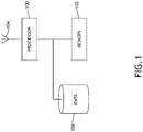
- FIG. 1
- shows a block diagram of a system suitable for implementing exemplary embodiments of the inventive concepts disclosed herein;
- FIG. 2
- shows a block diagram of a time division structure according to an exemplary embodiment;
- FIG. 3
- shows block diagrams of time division structures according to exemplary embodiments;
- FIG. 4
- shows block diagrams of time division structures according to exemplary embodiments;
- Before explaining at least one embodiment of the inventive concepts disclosed herein in detail, it is to be understood that the inventive concepts are not limited in their application to the details of construction and the arrangement of the components or steps or methodologies set forth in the following description or illustrated in the drawings. In the following detailed description of embodiments of the instant inventive concepts, numerous specific details are set forth in order to provide a more thorough understanding of the inventive concepts. However, it will be apparent to one of ordinary skill in the art having the benefit of the instant disclosure that the inventive concepts disclosed herein may be practiced without these specific details. In other instances, well-known features may not be described in detail to avoid unnecessarily complicating the instant disclosure. The inventive concepts disclosed herein are capable of other embodiments or of being practiced or carried out in various ways. Also, it is to be understood that the phraseology and terminology employed herein is for the purpose of description and should not be regarded as limiting.
- As used herein a letter following a reference numeral is intended to reference an embodiment of the feature or element that may be similar, but not necessarily identical, to a previously described element or feature bearing the same reference numeral (e.g., 1, 1a, 1b). Such shorthand notations are used for purposes of convenience only, and should not be construed to limit the inventive concepts disclosed herein in any way unless expressly stated to the contrary.
- Further, unless expressly stated to the contrary, "or" refers to an inclusive or and not to an exclusive or. For example, a condition A or B is satisfied by anyone of the following: A is true (or present) and B is false (or not present), A is false (or not present) and B is true (or present), and both A and B are true (or present).
- In addition, use of the "a" or "an" are employed to describe elements and components of embodiments of the instant inventive concepts. This is done merely for convenience and to give a general sense of the inventive concepts, and "a" and "an" are intended to include one or at least one and the singular also includes the plural unless it is obvious that it is meant otherwise.
- Finally, as used herein any reference to "one embodiment," or "some embodiments" means that a particular element, feature, structure, or characteristic described in connection with the embodiment is included in at least one embodiment of the inventive concepts disclosed herein. The appearances of the phrase "in some embodiments" in various places in the specification are not necessarily all referring to the same embodiment, and embodiments of the inventive concepts disclosed may include one or more of the features expressly described or inherently present herein, or any combination of sub-combination of two or more such features, along with any other features which may not necessarily be expressly described or inherently present in the instant disclosure.
- Broadly, embodiments of the inventive concepts disclosed herein are directed to a system and method for time division multiplexing voice and situational awareness data with defined transmission and retransmission windows. Retransmissions are synchronized such that the retransmissions appear to be aligned at the receiver and can be treated as artificial multipath receptions. Retransmission functionality may be more fully understood with reference to
U.S. Patent App. No. 16/810,542 (filed March 5, 2020 - Referring to
FIG. 1 , a block diagram of a system suitable for implementing exemplary embodiments of the inventive concepts disclosed herein is shown. The system includes aprocessor 100, amemory 102 connected to theprocessor 100 for embodying processor executable code, anantenna 104 connected to theprocessor 100 configured for HF communication, and adata storage element 106 connected to theprocessor 100 for allowing theprocessor 100 to receive and store data packets for retransmission during a relay window as described herein. When operating in an HF range (such as during NVIS operation or surface naval operations), bandwidth may be restricted such that reliable voice transmission and relay cannot operate alongside reliable situational awareness transmission and relay. Theprocessor 100 is configured to define a primary voice window wherein only a primary voice data source (a single node for the duration of a voice data transmission) transmits voice data packets, and a voice relay window wherein nodes in a self-organizing network will retransmit the voice data packets if previously received and attempt to receive voice data packets if not. Furthermore, theprocessor 100 is configured to define a situational awareness window wherein the node sends and receives situational awareness data, and a situational awareness relay window wherein nodes in the self-organizing network will retransmit any received situational awareness data. It may be appreciated that "situational awareness" more generically, is non-voice data traffic. - In at least one embodiment, while retransmissions by all retransmitting nodes must be identical for a given retransmission window, it does not necessarily have to be identical to the original transmission. This can be exploited by including additional forward error correction bits during the retransmission, allowing a node that receives transmissions in the original and retransmission windows to take advantage of a lower rate code than would be possible if the same information were transmitted in both. In one exemplary embodiment, a node may detect the original transmission, validate it, then create the appropriate retransmission from the detected data. Detection and validation must occur before retransmitting or risk creating interference by retransmitting erroneous data.
- In at least one embodiment, the system may prioritize reliability over voice quality and therefore may operate with a lower rate vocoder, for example a 1200 bps vocoder rather than a 2400 bps vocoder. It may be appreciated that if the situational awareness window and situational awareness relay window are each half the duration of the primary voice window, the primary voice window comprises 1/3 of the frame. In order to support a 2400 bps vocoder, the voice data source would have to run at three times that rate or 7200 bps for very long windows. For short windows, needed to support low latency voice, rates have to increase further, necessitating high signal-to-noise ratios for successful reception. Use of a 1200 bps vocoder, instead of a 2400 bps vocoder, improves this substantially, cutting the required burst data rates in half to levels where the signaling can be met with 8PSK modulation and high rate coding in a 3 kHz channel. Bit rate selection may be different where wider bandwidth channels are available.
- In at least one embodiment, voice users directly manage channel access and collision avoidance for voice; they listen and use standard radio procedures to minimize the likelihood of users transmitting over top of each other. The difficulty associated with avoiding voice collisions increases as the latency associated with voice transmissions increases. Making slots very small reduces latency, but increases the proportion of overhead associated with each slot. As a result, to maintain data rates sufficient to support digital vocoders, reducing slot sizes results in a requirement to increase modulation order (bits per symbol), reduce forward error correction coding, or otherwise reduce the robustness of the signal. The receiver may not begin outputting voice until after the receipt of the entire voice relay window. Effective latency is then from whenever the transmitting user presses push-to-talk (PTT) until after the voice relay window. In the worst case, the voice activates PTT just after a primary voice window and has to wait through an entire frame until the next primary voice window. As audio signals don't come out at the receiver until after the voice relay window, the latency is close to two full frames. It may be appreciated that data streams are divided into frames, which are then divided into time slots as described herein.
- In at least one embodiment, the
processor 100 defines control signal windows and control signal relay windows to send and receive original control signals and retransmit received control signals. The control signals synchronize various temporal windows in the time-division multiplexed signal so that all of the nodes in the self-organizing network operate in an appropriate phase. Furthermore, control signals may be used to indicate when a voice data packet may be expected. The control signals utilize the same relay architecture and are very short due to the limited amount of control information being conveyed. Minimizing the length of control signals is important and may preferentially use a robust low rate waveform, such as a Walsh encoded burst waveform. Control signals may include instructions to change signaling rates. - In at least one embodiment, the primary voice window and voice relay window may be reallocated to situational awareness data whenever no voice data packets are expected. In at least one embodiment, control signal windows may be relatively fixed in the frame while situational awareness windows and voice windows may be dynamically allocated via the control signals. Furthermore, control signals may allocate situational awareness windows to particular sets of nodes to suppress cross-talk.
- Referring to
FIG. 2 , a block diagram of a time division structure according to an exemplary embodiment is shown. The time-division multiplexed signal is temporally divided into aprimary voice window 200 when nodes in a self-organizing network send or receive new voice data packets, and asituational awareness window 202 when nodes send and receive situational awareness data from other nodes. The signal is also divided into avoice relay window 204 when nodes retransmit voice data packets if any where received, or receive retransmitted voice data packets if not. The signal is also divided into a situationalawareness relay window 206 when nodes retransmit received situational awareness data and receive retransmitted situational awareness data. -
Windows multiple relay windows - Referring to
FIG. 3 , block diagrams oftime division structures time division structure 312, a signal is divided intosituational awareness windows 300 when new situational awareness data is transmitted and received, and situationalawareness relay windows 304 when received situational awareness data is retransmitted and received. Furthermore,control signal windows 302 and controlsignal retransmission windows 306 are interposed and interleaved between thesituational awareness windows 300 and situationalawareness relay windows 304. During thecontrol signal windows 302 and controlsignal retransmission windows 306 control signals are sent, received and retransmitted to every node in a self-organizing network. Control signals may include synchronization information to define thevarious windows - In at least one embodiment, a second
time division structure 314, the signal is divided intosituational awareness windows 300 and situationalawareness relay windows 304, andprimary voice windows 308 andvoice relay windows 310. Duringprimary voice windows 308, a voice data source node transmits voice data packets; duringvoice relay windows 310, all nodes that have received the voice data packets, including the primary node, retransmit the voice data packets for any nodes that did not receive the voice data packets during theprimary voice window 308. - Control signals sent, received, and retransmitted during the
control signal windows 302 and controlsignal retransmission windows 306 may include an indication of voice data source node so that other nodes will refrain from transmitting during theprimary voice window 308. Voice data packets are generally more bandwidth intensive than situational awareness data, especially in the HF band; therefore, it is important to prevent interference duringprimary voice windows 308 andvoice relay windows 310. - Control signals may instruct the nodes in the network to add
primary voice windows 308 andvoice relay windows 310 dynamically when one of the nodes indicates an intent to transmit voice data packets. - In at least one embodiment, situational awareness and
voice windows situational awareness windows voice windows situational awareness window 300, then situationalawareness relay window 304, thenprimary voice window 308, then voicerelay window 310 withcontrol signal windows voice windows control signal windows - Referring to
FIG. 4 , block diagrams of time division structures 412, 414 according to exemplary embodiments are shown. In a first time division structure 412, a signal is divided intosituational awareness windows 400 and situationalawareness relay windows 404.Control signal windows 402 and controlsignal retransmission windows 406 are interposed and interleaved between thesituational awareness windows 400 and situationalawareness relay windows 404. - When an indication that a voice data packets are incoming, a second time division structure 414 may be implemented wherein the signal is divided into
situational awareness windows 400 and situationalawareness relay windows 404, andprimary voice windows 408 andvoice relay windows 410. Duringprimary voice windows 408, a voice data source node transmits voice data packets; duringvoice relay windows 410, all nodes that have received the voice data packets, including the primary node, retransmit the voice data packets for any nodes that did not receive the voice data packets during theprimary voice window 408. - Control signals may instruct the nodes in the network to add
primary voice windows 408 andvoice relay windows 410 dynamically when one of the nodes indicates an intent to transmit voice data packets. In at least one embodiment, situational awareness andvoice windows primary voice window 408 and situational awareness window 400) followed by retransmission windows (avoice relay window 410 and situational awareness relay window 404). Space may be reserved between the blocks ofprimary transmission windows retransmission windows control signal windows - In at least one embodiment, multiple networks may be stacked and operate at different frequencies, so that the
retransmission windows final retransmission window situational awareness windows voice windows - Originating transmissions may be sent at lower data rates (longer windows) to increase the likelihood of being received and relayed. Retransmission windows of voice and data could be combined into a single relay transmission, thereby reducing the number of transmissions with individual per transmission overhead. Multiple situational awareness windows could be aggregated into a single relay transmission by nodes that received all windows being aggregated.
- It is believed that the inventive concepts disclosed herein and many of their attendant advantages will be understood by the foregoing description of embodiments of the inventive concepts disclosed, and it will be apparent that various changes may be made in the form, construction, and arrangement of the components thereof without departing from the broad scope of the inventive concepts disclosed herein or without sacrificing all of their material advantages; and individual features from various embodiments may be combined to arrive at other embodiments. The form herein before described being merely an explanatory embodiment thereof, it is the intention of the following claims to encompass and include such changes. Furthermore, any of the features disclosed in relation to any of the individual embodiments may be incorporated into any other embodiment.
Claims (15)
- A method comprising:defining a primary voice window in a time division multiplexed signal;defining a situational awareness window in the time division multiplexed signal;defining a voice relay window in the time division multiplexed signal;defining a situational awareness relay window in the time division multiplexed signal;receiving a voice data packet during the primary voice window;receiving a situational awareness data packet during the situational awareness window;retransmitting the voice data packet to other network nodes in a plurality of network nodes during the voice relay window; andretransmitting the situational awareness data packet to other network nodes in the plurality of network nodes during the situational awareness relay window.
- The method of Claim 1, further comprising receiving a synchronization signal common to every network node in the plurality of network nodes,
wherein the primary voice window, situational awareness window, voice relay window, and situational awareness relay window are defined with respect to the synchronization signal. - The method of Claim 1, further comprising:defining one or more control signal windows in the time division multiplexed signal; anddefining one or more control signal relay windows in the time division multiplexed signal.
- The method of Claim 2, further comprising:receiving a control data packet indicating a primary voice node that will be sending a voice data packet in the primary voice window; andretransmitting the control data packet to other network nodes in the plurality of network nodes during the control signal relay window.
- The method of Claim 3, wherein the control data packet includes a bit rate and vocoder instruction; or
wherein the control data packet includes a schedule of assignments for situational awareness windows to subsets of nodes in the plurality of nodes. - The method of Claim 2, further comprising:sending a signal to other network nodes in the plurality of network nodes that the processor will be a primary voice data source during a subsequent primary voice window during the control signal window; andsending a voice data packet during the subsequent primary voice window.
- The method of Claim 1, further comprising:determining that there is no primary voice data source; andreallocating the primary voice window and voice relay window for situation awareness transmission and retransmission.
- A system comprising:
a plurality of network nodes, each network node comprising:a high frequency (HF) antenna (104); andat least one processor (100) in data communication with the HF antenna and a memory storing processor executable code for configuring the at least one processor to:define a primary voice window in a time division multiplexed signal;define a situational awareness window in the time division multiplexed signal;define a voice relay window in the time division multiplexed signal;define a situational awareness relay window in the time division multiplexed signal;receive a voice data packet during the primary voice window;receive a situational awareness data packet during the situational awareness window;retransmit the voice data packet to other network nodes in the plurality of network nodes during the voice relay window; andretransmit the situational awareness data packet to other network nodes in the plurality of network nodes during the situational awareness relay window. - The system of Claim 8, wherein the at least one processor (100) is further configured to receive a synchronization signal common to every network node in the plurality of network nodes,wherein the primary voice window, situational awareness window, voice relay window, and situational awareness relay window are defined with respect to the synchronization signal; and/orwherein the at least one processor (100) is further configured to:define one or more control signal windows in the time division multiplexed signal; anddefine one or more control signal relay windows in the time division multiplexed signal.
- The system of Claim 9, wherein the at least one processor (100) is further configured to:receive a control data packet indicating a primary voice node that will be sending a voice data packet in the primary voice window; andretransmit the control data packet to other network nodes in the plurality of network nodes during the control signal relay window, and preferablywherein the control data packet includes a bit rate and vocoder instruction.
- The system of Claim 9, wherein the at least one processor (100) is further configured to:send a signal to other network nodes in the plurality of network nodes that the processor will be a primary voice data source during a subsequent primary voice window during the control signal window; andsend a voice data packet during the subsequent primary voice window.
- A computer apparatus comprising:
at least one processor (100) in data communication with a memory storing processor executable code for configuring the at least one processor to:define a primary voice window in a time division multiplexed signal;define a situational awareness window in the time division multiplexed signal;define a voice relay window in the time division multiplexed signal;define a situational awareness relay window in the time division multiplexed signal;receive a voice data packet during the primary voice window;receive a situational awareness data packet during the situational awareness window;retransmit the voice data packet to one or more nodes in a network of nodes during the voice relay window; andretransmit the situational awareness data packet to at least one node in the network of nodes during the situational awareness relay window. - The computer apparatus of Claim 12, wherein the at least one processor (100) is further configured to receive a synchronization signal common to every node in the network of nodes,wherein the primary voice window, situational awareness window, voice relay window, and situational awareness relay window are defined with respect to the synchronization signal; and/orwherein the at least one processor (100) is further configured to:define one or more control signal windows in the time division multiplexed signal; anddefine one or more control signal relay windows in the time division multiplexed signal.
- The computer apparatus of Claim 13, wherein the at least one processor (100) is further configured to:receive a control data packet indicating a primary voice node that will be sending a voice data packet in the primary voice window; andretransmit the control data packet to at least one node in the network of nodes during the control signal relay window; orwherein the at least one processor (100) is further configured to:send a signal to at least one node in the network of nodes that the processor will be a primary voice data source during a subsequent primary voice window during the control signal window; andsend a voice data packet during the subsequent primary voice window.
- The computer apparatus of Claim 12, wherein the at least one processor (100) is further configured to:determine that there is no primary voice data source; andreallocate the primary voice window and voice relay window for situation awareness transmission and retransmission.
Applications Claiming Priority (1)
| Application Number | Priority Date | Filing Date | Title |
|---|---|---|---|
| US17/098,954 US11190862B1 (en) | 2020-11-16 | 2020-11-16 | Enhanced high frequency avalanche relay protocol |
Publications (2)
| Publication Number | Publication Date |
|---|---|
| EP4002927A1 true EP4002927A1 (en) | 2022-05-25 |
| EP4002927B1 EP4002927B1 (en) | 2025-12-24 |
Family
ID=78676393
Family Applications (1)
| Application Number | Title | Priority Date | Filing Date |
|---|---|---|---|
| EP21208601.1A Active EP4002927B1 (en) | 2020-11-16 | 2021-11-16 | Enhanced high frequency avalanche relay protocol |
Country Status (2)
| Country | Link |
|---|---|
| US (1) | US11190862B1 (en) |
| EP (1) | EP4002927B1 (en) |
Families Citing this family (3)
| Publication number | Priority date | Publication date | Assignee | Title |
|---|---|---|---|---|
| US12375208B2 (en) | 2022-06-20 | 2025-07-29 | Rockwell Collins, Inc. | Cooperative transmission continuous transmission enhancement |
| US12432794B1 (en) | 2023-02-02 | 2025-09-30 | Rockwell Collins, Inc. | Avalanche relay linking system |
| US12328149B1 (en) | 2023-02-02 | 2025-06-10 | Rockwell Collins, Inc. | Notification system and apparatus |
Citations (3)
| Publication number | Priority date | Publication date | Assignee | Title |
|---|---|---|---|---|
| US7103371B1 (en) * | 2003-10-22 | 2006-09-05 | Itt Manufacturing Enterprises, Inc. | Method and apparatus for dynamic voice reservation within wireless networks |
| US20060198324A1 (en) * | 2005-03-04 | 2006-09-07 | Annita Nerses | Method and apparatus for multipoint voice operation in a wireless, AD-HOC environment |
| US7626966B1 (en) * | 2005-01-06 | 2009-12-01 | Idealab | Ad hoc wireless communication system |
Family Cites Families (15)
| Publication number | Priority date | Publication date | Assignee | Title |
|---|---|---|---|---|
| US4639937A (en) | 1983-12-07 | 1987-01-27 | Harris Corporation | HF avalanche relay communication technique |
| US5703881A (en) | 1990-12-06 | 1997-12-30 | Hughes Electronics | Multi-subscriber unit for radio communication system and method |
| US5521925A (en) | 1993-09-09 | 1996-05-28 | Hughes Aircraft Company | Method and apparatus for providing mixed voice and data communication in a time division multiple access radio communication system |
| US5515379A (en) * | 1993-10-18 | 1996-05-07 | Motorola, Inc. | Time slot allocation method |
| US5506848A (en) * | 1994-06-22 | 1996-04-09 | At&T Corp. | Demand assignment system and method for mobile users in a community of interest |
| KR100212060B1 (en) | 1997-03-31 | 1999-08-02 | 윤종용 | Frame Structure for Time Division Multiple Access Communication System |
| US6411613B1 (en) | 1998-08-12 | 2002-06-25 | Lucent Technologies Inc. | Method for formatting and conveying information in a wireless telecommunication system |
| US6847821B1 (en) * | 1998-09-14 | 2005-01-25 | Nortel Networks Limited | Method and system in a wireless communications network for the simultaneous transmission of both voice and non-voice data over a single radio frequency channel |
| US6456633B1 (en) * | 1999-04-08 | 2002-09-24 | Avinta Communications, Inc. | Unified distributed voice and data local area networking |
| US20020126689A1 (en) * | 2000-12-29 | 2002-09-12 | Pivotech Systems, Inc. | System and method for dynamic local loop bandwidth multiplexing |
| US8289933B2 (en) | 2001-10-18 | 2012-10-16 | Alcatel Lucent | Hybrid transmission method for wireless communications |
| US20080080547A1 (en) | 2006-09-29 | 2008-04-03 | Motorola, Inc. | System and method for forming a time division multiple access frame in a simulcast system |
| US8699411B1 (en) | 2009-09-30 | 2014-04-15 | Google Inc. | Dynamic TDMA system for TV white space MIMO wireless |
| US9253773B2 (en) * | 2013-08-29 | 2016-02-02 | Motorola Solutions, Inc. | Method and apparatus for wirelessly transacting simultaneous voice and data on adjacent timeslots |
| US11357002B2 (en) | 2018-05-07 | 2022-06-07 | Qualcomm Incorporated | Transmission time interval integration for multiple radio access technologies |
-
2020
- 2020-11-16 US US17/098,954 patent/US11190862B1/en active Active
-
2021
- 2021-11-16 EP EP21208601.1A patent/EP4002927B1/en active Active
Patent Citations (3)
| Publication number | Priority date | Publication date | Assignee | Title |
|---|---|---|---|---|
| US7103371B1 (en) * | 2003-10-22 | 2006-09-05 | Itt Manufacturing Enterprises, Inc. | Method and apparatus for dynamic voice reservation within wireless networks |
| US7626966B1 (en) * | 2005-01-06 | 2009-12-01 | Idealab | Ad hoc wireless communication system |
| US20060198324A1 (en) * | 2005-03-04 | 2006-09-07 | Annita Nerses | Method and apparatus for multipoint voice operation in a wireless, AD-HOC environment |
Also Published As
| Publication number | Publication date |
|---|---|
| US11190862B1 (en) | 2021-11-30 |
| EP4002927B1 (en) | 2025-12-24 |
Similar Documents
| Publication | Publication Date | Title |
|---|---|---|
| EP4002927B1 (en) | Enhanced high frequency avalanche relay protocol | |
| US5663958A (en) | Method and apparatus for dynamically selecting the length of mobile station burst communications on the reverse digital control channel | |
| US5563895A (en) | Digital mobil E radio communication system | |
| US7969926B2 (en) | System and method for transmitting/receiving signal in a communication system | |
| US8522100B2 (en) | Radio communication apparatus and a method of transmitting a retransmission packet | |
| CN109547946B (en) | Audio data communication method | |
| CN109450490B (en) | A kind of voice data communication equipment and system | |
| US6359867B1 (en) | Dynamic channel allocation | |
| JPH11509065A (en) | Dual mode satellite / cellular terminal | |
| JPH0759161A (en) | Multiple access communication system, multiple access communication method, and communication device thereof | |
| FI108494B (en) | Signaling procedure and telecommunication system | |
| JPS6215941A (en) | Method and apparatus for searching vacant channel | |
| US6044086A (en) | Control signal transmission in digital radio telephony | |
| US20150296498A1 (en) | Flexible control channels for unplanned wireless networks | |
| JP7785756B2 (en) | Multi-channel time division multiplexed access method and system | |
| EP2430853B1 (en) | Method, device and system for data processing in a network | |
| US6173189B1 (en) | Method and apparatus for multi-protocol reverse channel infrastructure sharing | |
| CN110896346B (en) | Method for transmitting PUSCH, user equipment and base station | |
| AU2005226531B2 (en) | Method of signaling reverse channel information with minimal voice/data delay | |
| EP0671089B1 (en) | Method for digital half-duplex transmission | |
| US20140098718A1 (en) | Wireless communications system including single channel retransmission and related methods | |
| CN103313400A (en) | Signaling sending and receiving control method, network side equipment and user equipment (UE) | |
| WO2002039774A1 (en) | Method for allocating radio resources to mobile stations, telecommunications network and mobile station | |
| AU2021286261B2 (en) | A radio communication repeater, a radio communication system and method | |
| FI94696C (en) | Procedure for digital semiduplex transmission between two radio stations |
Legal Events
| Date | Code | Title | Description |
|---|---|---|---|
| PUAI | Public reference made under article 153(3) epc to a published international application that has entered the european phase |
Free format text: ORIGINAL CODE: 0009012 |
|
| STAA | Information on the status of an ep patent application or granted ep patent |
Free format text: STATUS: THE APPLICATION HAS BEEN PUBLISHED |
|
| AK | Designated contracting states |
Kind code of ref document: A1 Designated state(s): AL AT BE BG CH CY CZ DE DK EE ES FI FR GB GR HR HU IE IS IT LI LT LU LV MC MK MT NL NO PL PT RO RS SE SI SK SM TR |
|
| STAA | Information on the status of an ep patent application or granted ep patent |
Free format text: STATUS: REQUEST FOR EXAMINATION WAS MADE |
|
| 17P | Request for examination filed |
Effective date: 20221117 |
|
| RBV | Designated contracting states (corrected) |
Designated state(s): AL AT BE BG CH CY CZ DE DK EE ES FI FR GB GR HR HU IE IS IT LI LT LU LV MC MK MT NL NO PL PT RO RS SE SI SK SM TR |
|
| STAA | Information on the status of an ep patent application or granted ep patent |
Free format text: STATUS: EXAMINATION IS IN PROGRESS |
|
| 17Q | First examination report despatched |
Effective date: 20230525 |
|
| GRAP | Despatch of communication of intention to grant a patent |
Free format text: ORIGINAL CODE: EPIDOSNIGR1 |
|
| STAA | Information on the status of an ep patent application or granted ep patent |
Free format text: STATUS: GRANT OF PATENT IS INTENDED |
|
| INTG | Intention to grant announced |
Effective date: 20250701 |
|
| GRAS | Grant fee paid |
Free format text: ORIGINAL CODE: EPIDOSNIGR3 |
|
| GRAA | (expected) grant |
Free format text: ORIGINAL CODE: 0009210 |
|
| STAA | Information on the status of an ep patent application or granted ep patent |
Free format text: STATUS: THE PATENT HAS BEEN GRANTED |
|
| AK | Designated contracting states |
Kind code of ref document: B1 Designated state(s): AL AT BE BG CH CY CZ DE DK EE ES FI FR GB GR HR HU IE IS IT LI LT LU LV MC MK MT NL NO PL PT RO RS SE SI SK SM TR |
|
| REG | Reference to a national code |
Ref country code: CH Ref legal event code: F10 Free format text: ST27 STATUS EVENT CODE: U-0-0-F10-F00 (AS PROVIDED BY THE NATIONAL OFFICE) Effective date: 20251224 Ref country code: GB Ref legal event code: FG4D |
|
| REG | Reference to a national code |
Ref country code: DE Ref legal event code: R096 Ref document number: 602021044889 Country of ref document: DE |
|
| REG | Reference to a national code |
Ref country code: LT Ref legal event code: MG9D |
|
| PG25 | Lapsed in a contracting state [announced via postgrant information from national office to epo] |
Ref country code: NO Free format text: LAPSE BECAUSE OF FAILURE TO SUBMIT A TRANSLATION OF THE DESCRIPTION OR TO PAY THE FEE WITHIN THE PRESCRIBED TIME-LIMIT Effective date: 20260324 |
|
| PG25 | Lapsed in a contracting state [announced via postgrant information from national office to epo] |
Ref country code: HR Free format text: LAPSE BECAUSE OF FAILURE TO SUBMIT A TRANSLATION OF THE DESCRIPTION OR TO PAY THE FEE WITHIN THE PRESCRIBED TIME-LIMIT Effective date: 20251224 Ref country code: FI Free format text: LAPSE BECAUSE OF FAILURE TO SUBMIT A TRANSLATION OF THE DESCRIPTION OR TO PAY THE FEE WITHIN THE PRESCRIBED TIME-LIMIT Effective date: 20251224 |
|
| PG25 | Lapsed in a contracting state [announced via postgrant information from national office to epo] |
Ref country code: RS Free format text: LAPSE BECAUSE OF FAILURE TO SUBMIT A TRANSLATION OF THE DESCRIPTION OR TO PAY THE FEE WITHIN THE PRESCRIBED TIME-LIMIT Effective date: 20260324 |
|
| PG25 | Lapsed in a contracting state [announced via postgrant information from national office to epo] |
Ref country code: LV Free format text: LAPSE BECAUSE OF FAILURE TO SUBMIT A TRANSLATION OF THE DESCRIPTION OR TO PAY THE FEE WITHIN THE PRESCRIBED TIME-LIMIT Effective date: 20251224 |
|
| REG | Reference to a national code |
Ref country code: NL Ref legal event code: MP Effective date: 20251224 |
|
| PG25 | Lapsed in a contracting state [announced via postgrant information from national office to epo] |
Ref country code: BG Free format text: LAPSE BECAUSE OF FAILURE TO SUBMIT A TRANSLATION OF THE DESCRIPTION OR TO PAY THE FEE WITHIN THE PRESCRIBED TIME-LIMIT Effective date: 20251224 |