EP4002818A1 - Electronic device for providing camera preview image and operating method thereof - Google Patents
Electronic device for providing camera preview image and operating method thereof Download PDFInfo
- Publication number
- EP4002818A1 EP4002818A1 EP20849326.2A EP20849326A EP4002818A1 EP 4002818 A1 EP4002818 A1 EP 4002818A1 EP 20849326 A EP20849326 A EP 20849326A EP 4002818 A1 EP4002818 A1 EP 4002818A1
- Authority
- EP
- European Patent Office
- Prior art keywords
- electronic device
- camera
- preview image
- display
- field
- Prior art date
- Legal status (The legal status is an assumption and is not a legal conclusion. Google has not performed a legal analysis and makes no representation as to the accuracy of the status listed.)
- Pending
Links
- 238000011017 operating method Methods 0.000 title abstract description 4
- 238000004458 analytical method Methods 0.000 claims abstract description 30
- 230000004044 response Effects 0.000 claims abstract description 21
- 230000033001 locomotion Effects 0.000 claims description 13
- 238000000034 method Methods 0.000 claims description 8
- 230000000694 effects Effects 0.000 claims description 7
- 238000004891 communication Methods 0.000 description 38
- 230000006870 function Effects 0.000 description 32
- 238000010191 image analysis Methods 0.000 description 13
- 239000000758 substrate Substances 0.000 description 12
- 210000000887 face Anatomy 0.000 description 9
- 238000012545 processing Methods 0.000 description 7
- 230000004913 activation Effects 0.000 description 6
- 230000008859 change Effects 0.000 description 6
- 238000010586 diagram Methods 0.000 description 6
- 230000009849 deactivation Effects 0.000 description 5
- 238000004590 computer program Methods 0.000 description 4
- 230000001133 acceleration Effects 0.000 description 2
- 230000008878 coupling Effects 0.000 description 2
- 238000010168 coupling process Methods 0.000 description 2
- 238000005859 coupling reaction Methods 0.000 description 2
- 238000001514 detection method Methods 0.000 description 2
- 238000005516 engineering process Methods 0.000 description 2
- 230000005484 gravity Effects 0.000 description 2
- 230000008569 process Effects 0.000 description 2
- 230000035807 sensation Effects 0.000 description 2
- 230000003213 activating effect Effects 0.000 description 1
- 230000005540 biological transmission Effects 0.000 description 1
- 230000010267 cellular communication Effects 0.000 description 1
- 230000001413 cellular effect Effects 0.000 description 1
- 239000004020 conductor Substances 0.000 description 1
- 238000011161 development Methods 0.000 description 1
- 230000007613 environmental effect Effects 0.000 description 1
- 210000004709 eyebrow Anatomy 0.000 description 1
- 239000000446 fuel Substances 0.000 description 1
- 230000010354 integration Effects 0.000 description 1
- 230000003155 kinesthetic effect Effects 0.000 description 1
- 239000000463 material Substances 0.000 description 1
- 239000007769 metal material Substances 0.000 description 1
- 238000010295 mobile communication Methods 0.000 description 1
- 238000012986 modification Methods 0.000 description 1
- 230000004048 modification Effects 0.000 description 1
- 230000006855 networking Effects 0.000 description 1
- 230000003287 optical effect Effects 0.000 description 1
- 230000000737 periodic effect Effects 0.000 description 1
- 230000002093 peripheral effect Effects 0.000 description 1
- 230000005236 sound signal Effects 0.000 description 1
- 238000012546 transfer Methods 0.000 description 1
Images


Classifications
-
- G—PHYSICS
- G06—COMPUTING; CALCULATING OR COUNTING
- G06F—ELECTRIC DIGITAL DATA PROCESSING
- G06F1/00—Details not covered by groups G06F3/00 - G06F13/00 and G06F21/00
- G06F1/16—Constructional details or arrangements
- G06F1/1613—Constructional details or arrangements for portable computers
- G06F1/1633—Constructional details or arrangements of portable computers not specific to the type of enclosures covered by groups G06F1/1615 - G06F1/1626
- G06F1/1675—Miscellaneous details related to the relative movement between the different enclosures or enclosure parts
- G06F1/1677—Miscellaneous details related to the relative movement between the different enclosures or enclosure parts for detecting open or closed state or particular intermediate positions assumed by movable parts of the enclosure, e.g. detection of display lid position with respect to main body in a laptop, detection of opening of the cover of battery compartment
-
- G—PHYSICS
- G06—COMPUTING; CALCULATING OR COUNTING
- G06F—ELECTRIC DIGITAL DATA PROCESSING
- G06F1/00—Details not covered by groups G06F3/00 - G06F13/00 and G06F21/00
- G06F1/16—Constructional details or arrangements
- G06F1/1613—Constructional details or arrangements for portable computers
- G06F1/1615—Constructional details or arrangements for portable computers with several enclosures having relative motions, each enclosure supporting at least one I/O or computing function
- G06F1/1616—Constructional details or arrangements for portable computers with several enclosures having relative motions, each enclosure supporting at least one I/O or computing function with folding flat displays, e.g. laptop computers or notebooks having a clamshell configuration, with body parts pivoting to an open position around an axis parallel to the plane they define in closed position
-
- G—PHYSICS
- G06—COMPUTING; CALCULATING OR COUNTING
- G06F—ELECTRIC DIGITAL DATA PROCESSING
- G06F1/00—Details not covered by groups G06F3/00 - G06F13/00 and G06F21/00
- G06F1/16—Constructional details or arrangements
- G06F1/1613—Constructional details or arrangements for portable computers
- G06F1/1633—Constructional details or arrangements of portable computers not specific to the type of enclosures covered by groups G06F1/1615 - G06F1/1626
- G06F1/1637—Details related to the display arrangement, including those related to the mounting of the display in the housing
- G06F1/1647—Details related to the display arrangement, including those related to the mounting of the display in the housing including at least an additional display
-
- G—PHYSICS
- G06—COMPUTING; CALCULATING OR COUNTING
- G06F—ELECTRIC DIGITAL DATA PROCESSING
- G06F1/00—Details not covered by groups G06F3/00 - G06F13/00 and G06F21/00
- G06F1/16—Constructional details or arrangements
- G06F1/1613—Constructional details or arrangements for portable computers
- G06F1/1633—Constructional details or arrangements of portable computers not specific to the type of enclosures covered by groups G06F1/1615 - G06F1/1626
- G06F1/1637—Details related to the display arrangement, including those related to the mounting of the display in the housing
- G06F1/1652—Details related to the display arrangement, including those related to the mounting of the display in the housing the display being flexible, e.g. mimicking a sheet of paper, or rollable
-
- G—PHYSICS
- G06—COMPUTING; CALCULATING OR COUNTING
- G06F—ELECTRIC DIGITAL DATA PROCESSING
- G06F1/00—Details not covered by groups G06F3/00 - G06F13/00 and G06F21/00
- G06F1/16—Constructional details or arrangements
- G06F1/1613—Constructional details or arrangements for portable computers
- G06F1/1633—Constructional details or arrangements of portable computers not specific to the type of enclosures covered by groups G06F1/1615 - G06F1/1626
- G06F1/1684—Constructional details or arrangements related to integrated I/O peripherals not covered by groups G06F1/1635 - G06F1/1675
- G06F1/1686—Constructional details or arrangements related to integrated I/O peripherals not covered by groups G06F1/1635 - G06F1/1675 the I/O peripheral being an integrated camera
-
- G—PHYSICS
- G06—COMPUTING; CALCULATING OR COUNTING
- G06V—IMAGE OR VIDEO RECOGNITION OR UNDERSTANDING
- G06V40/00—Recognition of biometric, human-related or animal-related patterns in image or video data
- G06V40/10—Human or animal bodies, e.g. vehicle occupants or pedestrians; Body parts, e.g. hands
- G06V40/16—Human faces, e.g. facial parts, sketches or expressions
- G06V40/161—Detection; Localisation; Normalisation
- G06V40/165—Detection; Localisation; Normalisation using facial parts and geometric relationships
-
- H—ELECTRICITY
- H04—ELECTRIC COMMUNICATION TECHNIQUE
- H04M—TELEPHONIC COMMUNICATION
- H04M1/00—Substation equipment, e.g. for use by subscribers
- H04M1/02—Constructional features of telephone sets
- H04M1/0202—Portable telephone sets, e.g. cordless phones, mobile phones or bar type handsets
- H04M1/0206—Portable telephones comprising a plurality of mechanically joined movable body parts, e.g. hinged housings
- H04M1/0208—Portable telephones comprising a plurality of mechanically joined movable body parts, e.g. hinged housings characterized by the relative motions of the body parts
- H04M1/0214—Foldable telephones, i.e. with body parts pivoting to an open position around an axis parallel to the plane they define in closed position
- H04M1/0216—Foldable in one direction, i.e. using a one degree of freedom hinge
-
- H—ELECTRICITY
- H04—ELECTRIC COMMUNICATION TECHNIQUE
- H04M—TELEPHONIC COMMUNICATION
- H04M1/00—Substation equipment, e.g. for use by subscribers
- H04M1/72—Mobile telephones; Cordless telephones, i.e. devices for establishing wireless links to base stations without route selection
- H04M1/724—User interfaces specially adapted for cordless or mobile telephones
- H04M1/72403—User interfaces specially adapted for cordless or mobile telephones with means for local support of applications that increase the functionality
-
- H—ELECTRICITY
- H04—ELECTRIC COMMUNICATION TECHNIQUE
- H04N—PICTORIAL COMMUNICATION, e.g. TELEVISION
- H04N23/00—Cameras or camera modules comprising electronic image sensors; Control thereof
- H04N23/45—Cameras or camera modules comprising electronic image sensors; Control thereof for generating image signals from two or more image sensors being of different type or operating in different modes, e.g. with a CMOS sensor for moving images in combination with a charge-coupled device [CCD] for still images
-
- H—ELECTRICITY
- H04—ELECTRIC COMMUNICATION TECHNIQUE
- H04N—PICTORIAL COMMUNICATION, e.g. TELEVISION
- H04N23/00—Cameras or camera modules comprising electronic image sensors; Control thereof
- H04N23/50—Constructional details
- H04N23/53—Constructional details of electronic viewfinders, e.g. rotatable or detachable
-
- H—ELECTRICITY
- H04—ELECTRIC COMMUNICATION TECHNIQUE
- H04N—PICTORIAL COMMUNICATION, e.g. TELEVISION
- H04N23/00—Cameras or camera modules comprising electronic image sensors; Control thereof
- H04N23/60—Control of cameras or camera modules
- H04N23/61—Control of cameras or camera modules based on recognised objects
- H04N23/611—Control of cameras or camera modules based on recognised objects where the recognised objects include parts of the human body
-
- H—ELECTRICITY
- H04—ELECTRIC COMMUNICATION TECHNIQUE
- H04N—PICTORIAL COMMUNICATION, e.g. TELEVISION
- H04N23/00—Cameras or camera modules comprising electronic image sensors; Control thereof
- H04N23/60—Control of cameras or camera modules
- H04N23/63—Control of cameras or camera modules by using electronic viewfinders
- H04N23/631—Graphical user interfaces [GUI] specially adapted for controlling image capture or setting capture parameters
- H04N23/632—Graphical user interfaces [GUI] specially adapted for controlling image capture or setting capture parameters for displaying or modifying preview images prior to image capturing, e.g. variety of image resolutions or capturing parameters
-
- H—ELECTRICITY
- H04—ELECTRIC COMMUNICATION TECHNIQUE
- H04N—PICTORIAL COMMUNICATION, e.g. TELEVISION
- H04N23/00—Cameras or camera modules comprising electronic image sensors; Control thereof
- H04N23/60—Control of cameras or camera modules
- H04N23/63—Control of cameras or camera modules by using electronic viewfinders
- H04N23/633—Control of cameras or camera modules by using electronic viewfinders for displaying additional information relating to control or operation of the camera
- H04N23/635—Region indicators; Field of view indicators
-
- H—ELECTRICITY
- H04—ELECTRIC COMMUNICATION TECHNIQUE
- H04N—PICTORIAL COMMUNICATION, e.g. TELEVISION
- H04N23/00—Cameras or camera modules comprising electronic image sensors; Control thereof
- H04N23/60—Control of cameras or camera modules
- H04N23/698—Control of cameras or camera modules for achieving an enlarged field of view, e.g. panoramic image capture
-
- H—ELECTRICITY
- H04—ELECTRIC COMMUNICATION TECHNIQUE
- H04N—PICTORIAL COMMUNICATION, e.g. TELEVISION
- H04N23/00—Cameras or camera modules comprising electronic image sensors; Control thereof
- H04N23/90—Arrangement of cameras or camera modules, e.g. multiple cameras in TV studios or sports stadiums
-
- H—ELECTRICITY
- H05—ELECTRIC TECHNIQUES NOT OTHERWISE PROVIDED FOR
- H05K—PRINTED CIRCUITS; CASINGS OR CONSTRUCTIONAL DETAILS OF ELECTRIC APPARATUS; MANUFACTURE OF ASSEMBLAGES OF ELECTRICAL COMPONENTS
- H05K1/00—Printed circuits
- H05K1/02—Details
- H05K1/0277—Bendability or stretchability details
- H05K1/028—Bending or folding regions of flexible printed circuits
-
- G—PHYSICS
- G06—COMPUTING; CALCULATING OR COUNTING
- G06F—ELECTRIC DIGITAL DATA PROCESSING
- G06F2203/00—Indexing scheme relating to G06F3/00 - G06F3/048
- G06F2203/048—Indexing scheme relating to G06F3/048
- G06F2203/04803—Split screen, i.e. subdividing the display area or the window area into separate subareas
-
- H—ELECTRICITY
- H04—ELECTRIC COMMUNICATION TECHNIQUE
- H04M—TELEPHONIC COMMUNICATION
- H04M1/00—Substation equipment, e.g. for use by subscribers
- H04M1/02—Constructional features of telephone sets
- H04M1/0202—Portable telephone sets, e.g. cordless phones, mobile phones or bar type handsets
- H04M1/0206—Portable telephones comprising a plurality of mechanically joined movable body parts, e.g. hinged housings
- H04M1/0208—Portable telephones comprising a plurality of mechanically joined movable body parts, e.g. hinged housings characterized by the relative motions of the body parts
- H04M1/0214—Foldable telephones, i.e. with body parts pivoting to an open position around an axis parallel to the plane they define in closed position
-
- H—ELECTRICITY
- H04—ELECTRIC COMMUNICATION TECHNIQUE
- H04M—TELEPHONIC COMMUNICATION
- H04M2201/00—Electronic components, circuits, software, systems or apparatus used in telephone systems
- H04M2201/34—Microprocessors
-
- H—ELECTRICITY
- H04—ELECTRIC COMMUNICATION TECHNIQUE
- H04M—TELEPHONIC COMMUNICATION
- H04M2201/00—Electronic components, circuits, software, systems or apparatus used in telephone systems
- H04M2201/36—Memories
-
- H—ELECTRICITY
- H04—ELECTRIC COMMUNICATION TECHNIQUE
- H04M—TELEPHONIC COMMUNICATION
- H04M2201/00—Electronic components, circuits, software, systems or apparatus used in telephone systems
- H04M2201/38—Displays
-
- H—ELECTRICITY
- H04—ELECTRIC COMMUNICATION TECHNIQUE
- H04M—TELEPHONIC COMMUNICATION
- H04M2250/00—Details of telephonic subscriber devices
- H04M2250/52—Details of telephonic subscriber devices including functional features of a camera
Definitions
- the present disclosure relates to an electronic device for providing a preview image of a camera in response to folding or unfolding of a foldable device including a plurality of cameras and an operating method thereof.
- the electronic device may provide call functions such as a voice call and a video call, message transmission/reception functions such as a short message service (SMS)/multimedia message service (MMS) and e-mail, an electronic notebook function, a photographing function, a broadcast playback function, a video playback function, a music playback function, an Internet function, a messenger function, a game function or a social networking service (SNS) function.
- call functions such as a voice call and a video call
- message transmission/reception functions such as a short message service (SMS)/multimedia message service (MMS) and e-mail
- SMS short message service
- MMS multimedia message service
- e-mail electronic notebook function
- the electronic device may include a plurality of cameras including at least one front camera and at least one rear camera, to satisfy various user needs related to the photographing function.
- such an electronic device may be implemented to be foldable. That is, the electronic device may be folding based on a center region.
- the electronic device implemented to be foldable (hereafter, a foldable electronic device) may include more available surfaces, than an electronic device which is not.
- the foldable electronic device may include a plurality of cameras and a plurality of displays having different functions and performances.
- parameters related to the photographing e.g., a field of view, a resolution, an aspect ratio
- a foldable electronic device may include a plurality of cameras, at least one display, at least one processor operatively connected with the plurality of the cameras and the at least one display, and at least one memory operatively connected with the at least one processor, and the at least one memory may store instructions, when executed, causing the at least one processor to, while a first preview image corresponding to a first camera among the plurality of the cameras is displayed on the at least one display, select at least one other camera, based on an analysis result of at least one object included in the first preview image, in response to detecting folding or unfolding of the electronic device, display a second preview image corresponding to the selected at least one camera, and obtain a captured image based on the displayed second preview image.
- An operating method of a foldable electronic device may include, while a first preview image corresponding to a first camera among a plurality of cameras of the electronic device is displayed on at least one display of the electronic device, selecting at least one other camera of the electronic device, based on an analysis result of at least one object included in the first preview image, in response to detecting folding or unfolding of the electronic device, displaying a second preview image corresponding to the selected at least one camera, and obtaining a captured image based on the displayed second preview image.
- a foldable electronic device may, in a camera preview state, change setting related to preview image displaying (e.g., a camera providing a preview image, or an aspect ratio), in response to folding and/or unfolding of the foldable electronic device. Even if there is no user's explicit input, the foldable electronic device according to an embodiment of the present invention may select a camera for providing the preview image, and provide a new preview image according to an optimal setting value according to a use situation of the foldable electronic device, in response to the folding and/or the unfolding of the foldable electronic device. Thus, a continuous camera shooting environment appropriate for the user's shooting situation may be provided.
- change setting related to preview image displaying e.g., a camera providing a preview image, or an aspect ratio
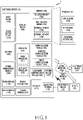
- Fig. 1 is a block diagram illustrating an electronic device 10 in a network environment 1 according to various embodiments.
- the electronic device 10 in the network environment 1 may communicate with an electronic device 12 via a first network 198 (e.g., a short-range wireless communication network), or an electronic device 14 or a server 18 via a second network 199 (e.g., a long-range wireless communication network).
- the electronic device 10 may communicate with the electronic device 14 via the server 18.
- the electronic device 10 may include a processor 120, memory 130, an input device 150, a sound output device 155, a display device 160, an audio module 170, a sensor module 176, an interface 177, a haptic module 179, a camera module 180, a power management module 188, a battery 189, a communication module 190, a subscriber identification module (SIM) 196, or an antenna module 197.
- at least one (e.g., the display device 160 or the camera module 180) of the components may be omitted from the electronic device 10, or one or more other components may be added in the electronic device 10.
- some of the components may be implemented as single integrated circuitry.
- the sensor module 176 e.g., a fingerprint sensor, an iris sensor, or an illuminance sensor
- the display device 160 e.g., a display
- the sensor module 176 e.g., a fingerprint sensor, an iris sensor, or an illuminance sensor
- the display device 160 e.
- the processor 120 may execute, for example, software (e.g., a program 141) to control at least one other component (e.g., a hardware or software component) of the electronic device 10 coupled with the processor 120, and may perform various data processing or computation. According to an embodiment, as at least part of the data processing or computation, the processor 120 may load a command or data received from another component (e.g., the sensor module 176 or the communication module 190) in volatile memory 132, process the command or the data stored in the volatile memory 132, and store resulting data in non-volatile memory 134.
- software e.g., a program 141
- the processor 120 may load a command or data received from another component (e.g., the sensor module 176 or the communication module 190) in volatile memory 132, process the command or the data stored in the volatile memory 132, and store resulting data in non-volatile memory 134.
- the processor 120 may include a main processor 121 (e.g., a central processing unit (CPU) or an application processor (AP)), and an auxiliary processor 123 (e.g., a graphics processing unit (GPU), an image signal processor (ISP), a sensor hub processor, or a communication processor (CP)) that is operable independently from, or in conjunction with, the main processor 121.
- auxiliary processor 123 may be adapted to consume less power than the main processor 121, or to be specific to a specified function.
- the auxiliary processor 123 may be implemented as separate from, or as part of the main processor 121.
- the auxiliary processor 123 may control at least some of functions or states related to at least one component (e.g., the display device 160, the sensor module 176, or the communication module 190) among the components of the electronic device 10, instead of the main processor 121 while the main processor 121 is in an inactive (e.g., sleep) state, or together with the main processor 121 while the main processor 121 is in an active state (e.g., executing an application).
- the auxiliary processor 123 e.g., an image signal processor or a communication processor
- the memory 130 may store various data used by at least one component (e.g., the processor 120 or the sensor module 176) of the electronic device 10.
- the various data may include, for example, software (e.g., the program 141) and input data or output data for a command related thereto.
- the memory 130 may include the volatile memory 132 or the non-volatile memory 134.
- the program 141 may be stored in the memory 130 as software, and may include, for example, an operating system (OS) 142, middleware 144, or an application 146.
- OS operating system
- middleware middleware
- application application
- the input device 150 may receive a command or data to be used by other component (e.g., the processor 120) of the electronic device 10, from the outside (e.g., a user) of the electronic device 10.
- the input device 150 may include, for example, a microphone, a mouse, a keyboard, or a digital pen (e.g., a stylus pen).
- the sound output device 155 may output sound signals to the outside of the electronic device 10.
- the sound output device 155 may include, for example, a speaker or a receiver.
- the speaker may be used for general purposes, such as playing multimedia or playing record, and the receiver may be used for an incoming calls. According to an embodiment, the receiver may be implemented as separate from, or as part of the speaker.
- the display device 160 may visually provide information to the outside (e.g., a user) of the electronic device 10.
- the display device 160 may include, for example, a display, a hologram device, or a projector and control circuitry to control a corresponding one of the display, hologram device, and projector.
- the display device 160 may include touch circuitry adapted to detect a touch, or sensor circuitry (e.g., a pressure sensor) adapted to measure the intensity of force incurred by the touch.
- the audio module 170 may convert a sound into an electrical signal and vice versa. According to an embodiment, the audio module 170 may obtain the sound via the input device 150, or output the sound via the sound output device 155 or a headphone of an external electronic device (e.g., an electronic device 12) directly (e.g., wiredly) or wirelessly coupled with the electronic device 10.
- an external electronic device e.g., an electronic device 12
- directly e.g., wiredly
- wirelessly e.g., wirelessly
- the sensor module 176 may detect an operational state (e.g., power or temperature) of the electronic device 10 or an environmental state (e.g., a state of a user) external to the electronic device 10, and then generate an electrical signal or data value corresponding to the detected state.
- the sensor module 176 may include, for example, a gesture sensor, a gyro sensor, an atmospheric pressure sensor, a magnetic sensor, an acceleration sensor, a grip sensor, a proximity sensor, a color sensor, an infrared (IR) sensor, a biometric sensor, a temperature sensor, a humidity sensor, or an illuminance sensor.
- the interface 177 may support one or more specified protocols to be used for the electronic device 10 to be coupled with the external electronic device (e.g., the electronic device 12) directly (e.g., wiredly) or wirelessly.
- the interface 177 may include, for example, a high definition multimedia interface (HDMI), a universal serial bus (USB) interface, a secure digital (SD) card interface, or an audio interface.
- HDMI high definition multimedia interface
- USB universal serial bus
- SD secure digital
- a connecting terminal 178 may include a connector via which the electronic device 10 may be physically connected with the external electronic device (e.g., the electronic device 12).
- the connecting terminal 178 may include, for example, a HDMI connector, a USB connector, a SD card connector, or an audio connector (e.g., a headphone connector).
- the haptic module 179 may convert an electrical signal into a mechanical stimulus (e.g., a vibration or a movement) or electrical stimulus which may be recognized by a user via his tactile sensation or kinesthetic sensation.
- the haptic module 179 may include, for example, a motor, a piezoelectric element, or an electric stimulator.
- the camera module 180 may capture a still image or moving images.
- the camera module 180 may include one or more lenses, image sensors, image signal processors, or flashes.
- the power management module 188 may manage power supplied to the electronic device 10. According to an embodiment, the power management module 188 may be implemented as at least part of, for example, a power management integrated circuit (PMIC).
- PMIC power management integrated circuit
- the battery 189 may supply power to at least one component of the electronic device 10.
- the battery 189 may include, for example, a primary cell which is not rechargeable, a secondary cell which is rechargeable, or a fuel cell.
- the communication module 190 may support establishing a direct (e.g., wired) communication channel or a wireless communication channel between the electronic device 10 and the external electronic device (e.g., the electronic device 12, the electronic device 14, or the server 18) and performing communication via the established communication channel.
- the communication module 190 may include one or more communication processors that are operable independently from the processor 120 (e.g., the application processor (AP)) and supports a direct (e.g., wired) communication or a wireless communication.
- AP application processor
- the communication module 190 may include a wireless communication module 192 (e.g., a cellular communication module, a short-range wireless communication module, or a global navigation satellite system (GNSS) communication module) or a wired communication module 194 (e.g., a local area network (LAN) communication module or a power line communication (PLC) module).
- a wireless communication module 192 e.g., a cellular communication module, a short-range wireless communication module, or a global navigation satellite system (GNSS) communication module
- GNSS global navigation satellite system
- wired communication module 194 e.g., a local area network (LAN) communication module or a power line communication (PLC) module.
- LAN local area network
- PLC power line communication
- a corresponding one of these communication modules may communicate with the external electronic device via the first network 198 (e.g., a short-range communication network, such as Bluetooth TM , wireless-fidelity (Wi-Fi) direct, or infrared data association (IrDA)) or the second network 199 (e.g., a long-range communication network, such as a cellular network, the Internet, or a computer network (e.g., LAN or wide area network (WAN)).
- the first network 198 e.g., a short-range communication network, such as Bluetooth TM , wireless-fidelity (Wi-Fi) direct, or infrared data association (IrDA)
- the second network 199 e.g., a long-range communication network, such as a cellular network, the Internet, or a computer network (e.g., LAN or wide area network (WAN)
- These various types of communication modules may be implemented as a single component (e.g., a single chip), or may be implemented as multi
- the wireless communication module 192 may identify and authenticate the electronic device 10 in a communication network, such as the first network 198 or the second network 199, using subscriber information (e.g., international mobile subscriber identity (IMSI)) stored in the subscriber identification module 196.
- subscriber information e.g., international mobile subscriber identity (IMSI)
- the antenna module 197 may transmit or receive a signal or power to or from the outside (e.g., the external electronic device) of the electronic device 10.
- the antenna module 197 may include an antenna including a radiating element including a conductive material or a conductive pattern formed in or on a substrate (e.g., PCB).
- the antenna module 197 may include a plurality of antennas. In such a case, at least one antenna appropriate for a communication scheme used in the communication network, such as the first network 198 or the second network 199, may be selected, for example, by the communication module 190 (e.g., the wireless communication module 192) from the plurality of antennas.
- the signal or the power may then be transmitted or received between the communication module 190 and the external electronic device via the selected at least one antenna.
- another component e.g., a radio frequency integrated circuit (RFIC)
- RFIC radio frequency integrated circuit
- At least some of the above-described components may be coupled mutually and communicate signals (e.g., commands or data) therebetween via an inter-peripheral communication scheme (e.g., a bus, general purpose input and output (GPIO), serial peripheral interface (SPI), or mobile industry processor interface (MIPI)).
- an inter-peripheral communication scheme e.g., a bus, general purpose input and output (GPIO), serial peripheral interface (SPI), or mobile industry processor interface (MIPI)
- commands or data may be transmitted or received between the electronic device 10 and the external electronic device 14 via the server 18 coupled with the second network 199.
- Each of the electronic devices 12 and 14 may be a device of a same type as, or a different type, from the electronic device 10.
- all or some of operations to be executed at the electronic device 10 may be executed at one or more of the external electronic devices 12, 14, or 18. For example, if the electronic device 10 should perform a function or a service automatically, or in response to a request from a user or another device, the electronic device 10, instead of, or in addition to, executing the function or the service, may request the one or more external electronic devices to perform at least part of the function or the service.
- the one or more external electronic devices receiving the request may perform the at least part of the function or the service requested, or an additional function or an additional service related to the request, and transfer an outcome of the performing to the electronic device 10.
- the electronic device 10 may provide the outcome, with or without further processing of the outcome, as at least part of a reply to the request.
- a cloud computing, distributed computing, or client-server computing technology may be used, for example.
- the electronic device may be one of various types of electronic devices.
- the electronic devices may include, for example, a portable communication device (e.g., a smartphone), a computer device, a portable multimedia device, a portable medical device, a camera, a wearable device, a home appliance, or the like. According to an embodiment of the disclosure, the electronic devices are not limited to those described above.
- each of such phrases as “A or B,” “at least one of A and B,” “at least one of A or B,” “A, B, or C,” “at least one of A, B, and C,” and “at least one of A, B, or C,” may include any one of, or all possible combinations of the items enumerated together in a corresponding one of the phrases.
- such terms as “1st” and “2nd,” or “first” and “second” may be used to simply distinguish a corresponding component from another, and does not limit the components in other aspect (e.g., importance or order).
- an element e.g., a first element
- operatively or “communicatively” as “coupled with,” coupled to,” “connected with,” “ or “connected to” another element
- the element may be coupled with the other element directly (e.g., wiredly), wirelessly, or via a third element.
- module may include a unit implemented in hardware, software, or firmware, and may interchangeably be used with other terms, for example, “logic,” “logic block,” “part,” or “circuitry”.
- a module may be a single integral component, or a minimum unit or part thereof, adapted to perform one or more functions.
- the module may be implemented in a form of an application-specific integrated circuit (ASIC).
- ASIC application-specific integrated circuit
- Various embodiments as set forth herein may be implemented as software (e.g., the program 141) including one or more instructions that are stored in a storage medium (e.g., internal memory 136 or external memory 138) that is readable by a machine (e.g., the electronic device 10) .
- a processor(e.g., the processor 120) of the machine e.g., the electronic device 10) may invoke at least one of the one or more instructions stored in the storage medium, and execute it, with or without using one or more other components under the control of the processor. This allows the machine to be operated to perform at least one function according to the at least one instruction invoked.
- the one or more instructions may include a code generated by a complier or a code executable by an interpreter.
- the machine-readable storage medium may be provided in the form of a non-transitory storage medium.
- the "non-transitory” storage medium is a tangible device, and may not include a signal (e.g., an electromagnetic wave), but this term does not differentiate between where data is semi-permanently stored in the storage medium and where the data is temporarily stored in the storage medium.
- a method according to various embodiments of the disclosure may be included and provided in a computer program product.
- the computer program product may be traded as a product between a seller and a buyer.
- the computer program product may be distributed in the form of a machine-readable storage medium (e.g., compact disc read only memory (CD-ROM)), or be distributed (e.g., downloaded or uploaded) online via an application store (e.g., PlayStore TM ), or between two user devices (e.g., smart phones) directly. If distributed online, at least part of the computer program product may be temporarily generated or at least temporarily stored in the machine-readable storage medium, such as memory of the manufacturer's server, a server of the application store, or a relay server.
- CD-ROM compact disc read only memory
- an application store e.g., PlayStore TM
- two user devices e.g., smart phones
- each component e.g., a module or a program of the above-described components may include a single entity or multiple entities. According to various embodiments, one or more of the above-described components may be omitted, or one or more other components may be added. Alternatively or additionally, a plurality of components (e.g., modules or programs) may be integrated into a single component. In such a case, according to various embodiments, the integrated component may still perform one or more functions of each of the plurality of components in the same or similar manner as they are performed by a corresponding one of the plurality of components before the integration.
- operations performed by the module, the program, or another component may be carried out sequentially, in parallel, repeatedly, or heuristically, or one or more of the operations may be executed in a different order or omitted, or one or more other operations may be added.
- an electronic device 10 may include a foldable housing 500, a hinge cover 530 which covers a foldable portion of the foldable housing 500, and a flexible or foldable display 552 (hereafter, referred to as a second display) disposed in a space formed by the foldable housing 500.
- a surface on which the second display 552 is disposed is defined as a first surface or a front surface of the electronic device 10 in this document.
- the opposite surface of the front surface is defined as a second surface or a rear surface of the electronic device 10.
- a surface surrounding a space between the front surface and the rear surface is defined as a third surface or a side surface of the electronic device 10.
- the electronic device 10 may correspond to the electronic device 10 disclosed in FIG. 1 .
- the foldable housing 500 may include a first housing structure 510, a second housing structure 520 including a sensor region 524, a first rear cover 580, and a second rear cover 590.
- the foldable housing 500 of the electronic device 10 is not limited to the shape and the coupling shown in FIGS. 2 and 3 , and may be implemented by other shape or combination and/or coupling of components.
- the first housing structure 510 and the first rear cover 580 may be integrally formed
- the second housing structure 520 and the second rear cover 590 may be integrally formed.
- the first housing structure 510 and the second housing structure 520 may be disposed on both sides based on a folding axis (axis A), and may have a shape which is symmetric on the whole with respect to the folding axis A.
- the first housing structure 510 and the second housing structure 520 may have different angles or distances depending on whether a state of the electronic device 10 is a flat state, a folded state, or an intermediate state to be explained.
- the second housing structure 520 may further include the sensor region 524 in which various sensors are disposed.
- the second housing structure 520 and the first housing structure 510 may have a mutually symmetric shape in other regions than the sensor region 524.
- the first housing structure 510 and the second housing structure 520 together may form a recess for accommodating the second display 552.
- the recess may have two or more different widths in a direction perpendicular to the folding axis A.
- the recess may have (1) a first width w1 between a first portion 510a parallel to the folding axis A in the first housing structure 510 and a first portion 520a formed at an edge of the sensor region 524 in the second housing structures 520, and (2) a second width w2 formed by a second portion 510b of the first housing structure 510 and a second portion 520b not corresponding to the sensor region 524 of the second housing structure 520 and parallel to the folding axis A.
- the second width w2 may be formed longer than the first width w1.
- the first portion 510a of the first housing structure 510 and the first portion 520a of the second housing structure 520 having the asymmetric shape may form the first width w1 of the recess
- the second portion 510b of the first housing structure 510 and the second portion 520b of the second housing structure 520 having the symmetrical shape may form the second width w2 of the recess.
- the first portion 520a and the second portion 520b of the second housing structure 520 may be different in distance from the folding axis A.
- the width of the recess is not limited to the illustrated example.
- the recess may have a plurality of widths based on the shape of the sensor region 524 or the portion having the asymmetric shape of the first housing structure 510 and the second housing structure 520.
- At least part of the first housing structure 510 and the second housing structure 520 may be formed of a metallic material or a nonmetallic material having rigidity of a magnitude selected to support the second display 552.
- the sensor region 524 may be formed to have a designated region adjacent to one corner of the second housing structure 520.
- the arrangement, the shape, and the size of the sensor region 524 are not limited to the illustrated example.
- the sensor region 524 may be provided at another corner of the second housing structure 520 or an arbitrary region between an upper corner and a lower corner.
- components for performing various functions imbedded in the electronic device 10 may be exposed to the front surface of the electronic device 10 through the sensor region 524, or through one or more openings provided in the sensor region 524.
- the components may include various sensors.
- the sensors may include, for example, at least one of a front camera, a receiver or a proximity sensor.
- the front camera may correspond to at least one of the second front camera 542 and the third front camera 543.
- the front camera may further include a fourth front camera (not shown) which is a camera for applying a special effect to a captured image.
- the fourth front camera may be a camera for applying the special effect (e.g., bokeh or out-focusing, telephoto, blur) to the captured image.
- the first rear cover 580 may be disposed on one side of the folding axis on the rear surface of the electronic device 10, and may have, for example, a substantially rectangular periphery, and the periphery may be surrounded by the first housing structure 510.
- the second rear cover 590 may be disposed on the other side of the folding axis on the rear surface of the electronic device 10, and its periphery may be surrounded by the second housing structure 520.
- the first rear cover 580 and the second rear cover 590 may have a substantially symmetrical shape based on the folding axis (the axis A). However, it is merely an example, and the first rear cover 580 and the second rear cover 590 do not necessarily have the symmetrical shape.
- the electronic device 10 may include the first rear cover 580 and the second rear cover 590 of various shapes.
- the first rear cover 580 may be integrally formed with the first housing structure 510
- the second rear cover 590 may be integrally formed with the second housing structure 520.
- the first rear cover 580, the second rear cover 590, the first housing structure 510, and the second housing structure 520 may form a space for mounting various components (e.g., a printed circuit board, or a battery) of the electronic device 10.
- one or more components may be disposed or visually exposed on the rear surface of the electronic device 10.
- at least part of at least one front camera e.g., the first front camera 541
- at least part of the first display 551 may be visually exposed through a first rear region 582 of the first rear cover 580.
- one or more components or sensors may be visually exposed through a second rear region 592 of the second rear cover 590.
- the sensors may include a proximity sensor and/or a rear camera.
- the rear camera may correspond to at least one of a first rear camera 341, a second rear camera 342, and a third rear camera 343.
- the rear camera may further include a fourth rear camera (not shown) which is a camera for applying a special effect to the captured image.
- the fourth rear camera (not shown) may be the camera for applying the special effect (e.g., bokeh or out-focusing, telephoto, blur) to the captured image.
- the first front camera 541 may support a first field of view range (or correspond to the first field of view range).
- the first field of view range may be a field of view range for displaying the preview image in a normal mode.
- the first field of view range may correspond to a range of 40 degrees through 60 degrees.
- the second front camera 542 and the third front camera 543 may correspond to different functions or performances respectively, and may have higher specifications than the first front camera 541.
- the second front camera 542 may correspond to a second field of view range (e.g., 60 through 90 degrees) (or support the second field of view range)
- the third front camera 543 may correspond to a third field of view range (90 degrees through 180 degrees)
- the second field of view range and the third field of view range may be wider field of view ranges than the first field of view range corresponding to the first front camera 541.
- the third field of view range may be a wider field of view range than the second field of view range.
- the second front camera 542 and the third front camera 543 may support a higher resolution than the first front camera 541.
- the first rear camera 341, the second rear camera 342, and the third rear camera 343 may correspond to different functions or performances.
- the first rear camera 341 may correspond to the second field of view range (or support the second field of view range)
- the second rear camera 342 may correspond to the first field of view range which is a narrower field of view range than the second field of view range
- the first field of view range may correspond to a telephoto or close-up mode.
- the third rear camera 343 may correspond to a third field of view range which is a wider field of view range than the second field of view range.
- the second field of view range corresponding to the first rear camera 341 may correspond to a field of view range for displaying the preview image in a wide-angle mode.
- the second rear camera 342 may correspond to a tele camera for magnifying and capturing a subject.
- the third field of view range corresponding to the third rear camera 343 may correspond to a field of view range for displaying the preview image in an ultra-wide-angle mode.
- the hinge cover 530 may be disposed between the first housing structure 510 and the second housing structure 520, and configured to cover an internal part (e.g., a hinge structure). In an embodiment, the hinge cover 530 may be covered by a part of the first housing structure 510 and the second housing structure 520, or exposed to outside, depending on the state (the flat state or the folded state) of the electronic device 10.
- the hinge cover 530 may be covered by the first housing structure 510 and the second housing structure 520 not to be exposed.
- the hinge cover 530 may be exposed to the outside between the first housing structure 510 and the second housing structure 520.
- the hinge cover 530 may be partially exposed to the outside between the first housing structure 510 and the second housing structure 520.
- the exposed region may be less than the fully folded state.
- the hinge cover 530 may include a curved surface.
- the second display 552 may be disposed on a space formed by the foldable housing 500.
- the second display 552 may be mounted on a recess formed by the foldable housing 500, and construct most of the front surface of the electronic device 10.
- the front surface of the electronic device 10 may include the second display 552 and some region of the first housing structure 510 and some region of the second housing structure 520 adjacent to the second display 552.
- the rear surface of the electronic device 10 may include the first rear cover 580, some region of the first housing structure 510 adjacent to the first rear cover 580, the second rear cover 590, and some region of the second housing structure 520 adjacent to the second rear cover 590.
- the second display 552 may indicate a display in which at least some region may be transformed into a flat surface or a curved surface.
- the second display 552 may include a folding region 103, a first region 101 disposed on one side (a left side of the folding region 103 shown in FIG. 2 ) based on the folding region and a second region 102 disposed on the other side (a right side of the folding region 103 shown in FIG. 2 ).
- the region division of the second display 552 shown in FIG. 2 is merely an example, and the second display 552 may be divided into a plurality of (e.g., four or more or two) regions according to its structure or function.
- the region of the second display 552 may be divided by the folding region 103 or the folding axis (axis A) extending in parallel to the y-axis in the embodiment shown in FIG. 2 , but the second display 552 may be divided based on another folding region (e.g., a folding region parallel to the x-axis) or another folding axis (e.g., a folding axis parallel to the x-axis) in an embodiment.
- the first region 101 and the second region 102 may have a shape which is symmetric on the whole based on the folding region 103. However, unlike the first region 101, the second region 102 may include a notch which is cut according to the presence of the sensor region 524, but may have the shape symmetrical to the first region 101 in other regions. In other words, the first region 101 and the second region 102 may include the portion having the symmetrical shape, and the having the asymmetrical shape.
- first housing structure 510 and the second housing structure 520 and each region of the second display 552 are described according to the state of the electronic device 10 (e.g., the flat state and the folded state).
- the first housing structure 510 and the second housing structure 520 may be arranged to make an angle of 180 degrees and face the same direction.
- a surface of the first region 101 and a surface of the second region 102 of the second display 552 may form 180 degrees, and face the same direction (e.g., the front direction of the electronic device).
- the folding region 103 may form the same plane as the first region 101 and the second region 102.
- the first housing structure 510 and the second housing structure 520 may be disposed to face each other.
- the surface of the first region 101 and the surface of the second region 102 of the second display 552 may form a narrow angle (e.g., between 0 degree and 10 degrees), and face each other.
- At least part of the folding region 103 may be formed as a curved surface having a designated curvature.
- the first housing structure 510 and the second housing structure 520 may be disposed at a certain angle.
- the surface of the first region 101 and the surface of the second region 102 of the second display 552 may form an angle which is greater than the folded state and smaller than the flat state.
- At least part of the folding region 103 may be formed as a curved surface having a designated curvature, wherein the curvature may be smaller than that of the folded state.
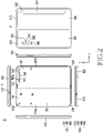
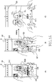
- FIG. 4 is an exploded perspective view of an electronic device according to various embodiments.
- the electronic device 10 may include a display unit 20, a bracket assembly 30, a substrate unit 600, a first housing structure 510, a second housing structure 520, a first rear cover 580 and a second rear cover 590.
- the display unit 20 may be referred to as a display module or a display assembly.
- the display unit 20 may include the second display 552, and one or more plates or layers 140 on which the second display 552 is mounted.
- the plate 140 may be disposed between the second display 552 and the bracket assembly 30.
- the second display 552 may be disposed on at least a part of one surface (e.g., an upper surface based on FIG. 3 ) of the plate 140.
- the plate 140 may be formed in a shape corresponding to the second display 552. For example, some region of the plate 140 may be formed in a shape corresponding to a notch 104 of the second display 552.
- the bracket assembly 30 may include a first bracket 410, a second bracket 420, a hinge structure disposed between the first bracket 410 and the second bracket 420, a hinge cover 530 for covering the hinge structure when viewed from the outside, and a wiring member 430 (e.g., a flexible printed circuit (FPC)) crossing the first bracket 410 and the second bracket 420.
- a wiring member 430 e.g., a flexible printed circuit (FPC)
- the bracket assembly 30 may be disposed, between the plate 140 and the substrate unit 600.
- the first bracket 410 may be disposed between the first region 101 of the second display 552 and the first substrate 610.
- the second bracket 420 may be disposed between the second region 102 of the second display 552 and the second substrate 620.
- the wiring member 430 and at least part of the hinge structure 300 may be disposed inside the bracket assembly 30.
- the wiring member 430 may be disposed in a direction crossing the first bracket 410 and the second bracket 420 (e.g., in the x-axis direction).
- the wiring member 430 may be disposed in a direction (e.g., the x-axis direction) perpendicular to the folding axis (e.g., the y-axis or the folding axis A of FIG. 1 ) of the folding region 103 of the electronic device 10.
- the substrate unit 600 may include, as mentioned above, the first substrate 610 disposed on the first bracket 410 and the second substrate 620 disposed on the second bracket 420.
- the first substrate 610 and the second substrate 620 may be disposed inside a space formed by the bracket assembly 30, the first housing structure 510, the second housing structure 520, the first rear cover 580 and the second rear cover 590.
- Components for implementing various functions of the electronic device 10 may be mounted on the first substrate 610 and the second substrate 620.
- the first housing structure 510 and the second housing structure 520 may be assembled to be coupled to both sides of the bracket assembly 30 while the display unit 20 is coupled to the bracket assembly 30. As will be described later, the first housing structure 510 and the second housing structure 520 may slide on both sides of the bracket assembly 30 to be coupled with the bracket assembly 30.
- the first housing structure 510 may include a first rotation support surface 512
- the second housing structure 520 may include a second rotation support surface 522 corresponding to the first rotation support surface 512.
- the first rotation support surface 512 and the second rotation support surface 522 may include a curved surface corresponding to the curved surface included in the hinge cover 530.
- the first rotation support surface 512 and the second rotation support surface 522 may cover the hinge cover 530 not to expose the hinge cover 530 to the rear surface of the electronic device 10 or to expose minimum. Meanwhile, if the electronic device 10 is in the folded state (e.g., the electronic device of FIG. 2 ), the first rotation support surface 512 and the second rotation support surface 522 may rotate along the curved surface included in the hinge cover 530 to expose the hinge cover 530 maximum to the rear surface of the electronic device 10.
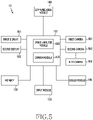
- FIG. 5 is a block diagram of an electronic device 10 according to embodiments of the present invention.
- the electronic device 10 may include a processor 120, a communication module 190, a memory 130, an input module 150, a first display 551, a second display 552, and a first through N-th cameras 561 through 569.
- N may be a natural number equal to or greater than 3.
- the processor 120 may control at least one component included in the electronic device 10.
- the processor 120 may control the first display 551, to display a first preview image corresponding to the first camera 561.
- the processor 120 may analyze at least one object included in the first preview image.
- the processor 120 may include an image analysis module 525 and a camera module 526. In an embodiment, the processor 120 may execute the image analysis module 525 and the camera module 526. In an embodiment, the processor 120 may control at least one component included in the electronic device 10 through the image analysis module 525 and the camera module 526. In an embodiment, the image analysis module 525 and the camera module 526 may be implemented as a physical circuit, or as a software program.
- the image analysis module 525 may analyze at least one object included in the preview image (e.g., the first preview image) displayed on the display (e.g., the first display 551). In an embodiment, in analyzing at least one object, the image analysis module 525 may determine characteristic information (e.g., size, color, shape, shadow, geometric characteristics, motion information, or movement direction information) of at least one object. In an embodiment, in analyzing at least one object, the image analysis module 525 may determine a type (e.g., a person, an animal, a building, or a food) of the at least one object. The characteristic information of the at least one object may be used to determine the type of the at least one object.
- characteristic information e.g., size, color, shape, shadow, geometric characteristics, motion information, or movement direction information
- object analysis result information which is generated at the image analysis module 525, may be provided to the camera module 526.
- the camera module 526 may process camera preview image data input from the first through N-th cameras 561 through 569. For example, the camera module 526 may forward the first preview image data input from the first camera 561 to the image analysis module 525, or receive the object analysis result information from the image analysis module 525. For example, the camera module 526 may control the first display 551 corresponding to the first camera 561, to display the first preview image input from the first camera 561.
- the camera module 526 may select at least one camera (e.g., the second camera 562) to be activated in response to the folding and/or the unfolding of the electronic device 10. In an embodiment, the camera module 526 may forward the object analysis result information (or, information generated by processing the object analysis result information) received from the image analysis module 525, to the at least one camera selected. In an embodiment, if a designated condition is satisfied, the camera module 526 may provide the information to the at least one selected camera. In an embodiment, the designated condition may be activation of the at least one selected camera (e.g., the second camera 562).
- the designated condition may be detection of the folding, or detection of the unfolding of the electronic device 10.
- the camera module 526 may forward the object analysis result information received from the image analysis module 525, or the information generated by processing the object analysis result information, to the at least one selected camera, if activating the at least one selected camera (e.g., the second camera 562) (e.g., if detecting the folding and/or the unfolding of the electronic device 10).
- At least one camera activated may recognize at least one subject, using the information from the camera module 526.
- At least one camera activated may recognize at least one subject faster than not using the information, by use of the information from the camera module 526.
- the first through the N-th cameras 561 through 569 may embrace a plurality of cameras included in the electronic device 10.
- the first camera 561 may correspond to the first front camera 541 disclosed in FIG. 2
- the second camera 562 and a third camera may correspond to the second front camera 542 and the third front camera 543 respectively disclosed in FIG. 2
- the first camera 561, the second camera 562, and the third camera may correspond to the first rear camera 341, the second rear camera 342, and the third rear camera 343 respectively shown in FIG. 3 .
- At least one camera e.g., the first camera 561) among the first through N-th cameras 561 through 569 may correspond to the first display 551, and at least one another camera (e.g., the second camera 561, and the third camera (not shown)) may correspond to the second display 552.
- a preview image of the first camera 561 may be displayed on the first display 551
- a preview image of the second camera 562 or the third camera (not shown) may be displayed on the second display 552.
- the first through N-th cameras 561 through 569 may support different field of view ranges. However, this is only an example, and at least two cameras of the first through N-th cameras 561 through 569 may support the same field of view range.
- the first camera 561 may support a first field of view range.
- the second camera 562 may support a second field of view range.
- the third camera (not shown) may support a third field of view range.
- the first field of view range may be a view angle range for displaying the preview image in the normal mode.
- the second field of view range may be a view angle range for displaying the preview image in the wide-angle mode.
- the third field of view range may be a view angle range for displaying the preview image in the ultra-wide-angle mode.
- the first field of view range may have a range of 40 through 60 degrees (°).
- the second field of view range may have a range of 60 to 90 degrees (°).
- the third field of view range may have a range of 90 to 180 degrees (°).
- the first through N-th cameras 561 through 569 may have different resolutions. However, this is only an example, and at least two cameras of the first through N-th cameras 561 through 569 may have the same resolution.
- the first display 551 and the second display 552 may display content.
- content For example, an application execution screen, an image (e.g., the preview image of the camera), a video, a call/message notification, and so on may be displayed.
- the first display 551 may have a vertical length longer than a horizontal length. Hence, even if a preview image corresponding to the same camera is displayed based on an aspect ratio in which the horizontal length is longer than the vertical length, the margin may increase compared to the opposite case.
- the second display 552 may have the horizontal length longer than the vertical length. Hence, even if a preview image corresponding to the same camera is displayed based on an aspect ratio in which the vertical length is longer than the horizontal length, the margin may increase compared to the opposite case.
- the memory 130 may store instructions for the electronic device 10 to carry out one or more operations according to embodiments of the present invention, under control of the processor 120.
- the memory 130 may store instructions causing the processor 120 to select at least one camera based on the analysis result of at least one object displayed in the first preview image.
- the memory 130 may store user history data, or user preference information related to the camera shooting.
- the input module 150 may be used for the electronic device 10 to receive a user input.
- the input module 150 may include a physical user interface such as a button.
- the electronic device 10 may receive a user input for obtaining a captured image, and a user input for switching the camera or the display.
- the sensor module 176 may be disposed inside the foldable housing 500 or the hinge cover 530.
- the sensor module 176 may include at least one of an angle sensor, a gyro sensor, an acceleration sensor, and a grip sensor.
- sensor information of the sensor module 176 may be used for the processor 120 to identify which one of the flat state, the folded state, or the intermediate state the current state of the electronic device 10 corresponds to, or to detect state change (e.g., folding (changing from the flat state to the folded state), or unfolding (changing from the folded state to the flat state) of the electronic device 10.
- the sensor module 176 may provide the sensor information used to detect the folding or the unfolding of the electronic device 10 to the processor 120 on a periodic basis or at event occurrence.
- FIG. 6 illustrates an operation sequence of an electronic device (e.g., the electronic device 10) according to embodiments of the present invention.
- FIG. 6 may be described with reference to the components of the electronic device 10 of FIG. 1 through FIG. 5 .
- the operations disclosed in FIG. 6 may be performed by the electronic device 10, under the control of the processor 120 of FIG. 5 . Hereafter, it is described that the electronic device 10 performs the operations disclosed in FIG. 6 .
- the electronic device 10 may display the first preview image.
- the electronic device 10 displaying the first preview image may be in the folded (e.g., in-folded) state.
- the first preview image may be a preview image corresponding to the first front camera (e.g., the first front camera 541).
- the electronic device 10 may display the first preview image on the first display 551 corresponding to the first front camera 541.
- the first front camera 541 may correspond to the first field of view range.
- the first preview image may be a preview image corresponding to the first rear camera (e.g., the first rear camera 341).
- the electronic device 10 may display the first preview image on the first display 551 corresponding to the first rear camera 341.
- the first rear camera 341 may correspond to the second field of view range.
- the electronic device 10 may analyze at least one object displayed in the first preview image.
- the electronic device 10 may analyze at least one object by conducting a scene recognition function (e.g., a face recognition function).
- a scene recognition function e.g., a face recognition function
- the electronic device 10 may determine characteristic information (e.g., size, color, shape, shadow, and geometric characteristics) of the at least one object.
- the electronic device 10 may determine the type (e.g., a person, an animal, a building, food) of the at least one object, based on the determined characteristic information.
- the electronic device 10 may select at least one camera, based on the analysis result.
- the electronic device 10 may select at least one camera, among all of the cameras included in the electronic device 10.
- the electronic device 10 may select at least one camera, among other cameras than the camera (e.g., the first front camera 541) corresponding to the preview image currently being displayed.
- the camera corresponding to the preview image currently displayed is the front camera, at least one camera may be selected from the other front cameras, and if the camera corresponding to the preview image currently displayed is the rear camera, at least one camera may be selected from the other rear cameras.
- the electronic device 10 may select at least one camera, by considering the current folding state of the electronic device 10. For example, currently in the folded state, the electronic device 10 may select at least one camera, from cameras (e.g., the second front camera 542 and the third front cameras 543) which may be effectively used for photographing if the electronic device 10 is to be unfolded. For example, currently in the flat state, the electronic device 10 may select at least one camera, from cameras (e.g., the first front camera 541) which may be effectively used for photographing if the electronic device 10 is to be folded.
- cameras e.g., the second front camera 542 and the third front cameras 543
- the electronic device 10 may select at least one camera, from cameras (e.g., the first front camera 541) which may be effectively used for photographing if the electronic device 10 is to be folded.
- the electronic device 10 may select at least one camera further based on display properties (e.g., a display size and supported resolutions).
- display properties e.g., a display size and supported resolutions.
- the at least one camera selected in operation 630 may be activated in response to the folding/unfolding of the electronic device 10. For example, if the second front camera 542 is selected in operation 630, the electronic device 10 may activate the selected second front camera 542 in response to the unfolding of the electronic device 10, and display a preview image of the selected second front camera 542.
- the electronic device 10 may identify whether folding or unfolding of the electronic device 10 is detected. For example, the electronic device 10 may identify that the folding of the electronic device 10 is detected, by identifying that the state of the electronic device 10 is changed from the flat state (or the intermediate state) to the folded state. For example, by identifying that the state of the electronic device 10 is changed from the folded state to the flat state, it may identify that the unfolding of the electronic device 10 is detected. The electronic device 10 may identify whether the folding or the unfolding is detected, using the sensor information of the sensor module 176. In an embodiment, the electronic device 10 may identify the state change of the electronic device 10.
- the electronic device 10 may identify the state change of the electronic device 10 from a first state (e.g., the folded state) to other state (e.g., the intermediate state, or the flat state) than the first state. In an embodiment, if identifying the folding state change of the electronic device 10, the electronic device 10 may identify that the folding or the unfolding is detected.
- a first state e.g., the folded state
- other state e.g., the intermediate state, or the flat state
- the electronic device 10 may display a second preview image corresponding to the selected camera.
- the electronic device 10 displaying the second preview image may be in the unfolded state.
- the electronic device 10 may display the second preview image corresponding to the selected camera on a corresponding display.
- the electronic device 10 may activate the selected camera and the display corresponding to the selected camera, and display the second preview image corresponding to the activated camera on the activated display. In an embodiment, the electronic device 10 may deactivate the camera corresponding to the first preview image and the display displaying the first preview image.
- the electronic device 10 may activate the second front camera 542 and the second front camera 542 corresponding to the second front camera 542, and display the second preview image corresponding to the second front camera 542 on the second display 552.
- the electronic device 10 may display the second preview image corresponding to the second front camera 542, based on a specific field of view included in the field of view range corresponding to the second front camera 542. For example, if the second front camera 542 corresponds to the second field of view (e.g., 60 degrees through 90 degrees) for displaying the preview image in the wide-angle mode, the electronic device 10 may display the second preview image based on a 75-degree field of view. In an embodiment, in determining the specific field of view within the second field of view range, the electronic device 10 may consider properties (e.g., a size, a resolution) of the second display 552 corresponding to the second front camera 542.
- properties e.g., a size, a resolution
- the electronic device 10 may determine an aspect ratio (e.g., 16:9, 4:3, 1:1, 3:4, 9:16, Full) associated with the displaying of the second preview image, and display the second preview image based on the determined aspect ratio.
- an aspect ratio e.g., 16:9, 4:3, 1:1, 3:4, 9:16, Full
- the electronic device 10 may determine the aspect ratio of the preview image based on an analysis result of at least one object (e.g., arrangement information of at least one object) displayed in the first preview image, or the user preference information stored in the memory 130.
- at least one object e.g., arrangement information of at least one object
- the user preference information stored in the memory 130.
- the electronic device 10 may determine the aspect ratio of the second preview image further based on the size or the ratio of the width and height of the display corresponding to the selected camera.
- the electronic device 10 may obtain a captured image.
- the electronic device 10 may acquire the captured image based on the displayed second preview image.
- the user input for obtaining the captured image may be a user input to a graphic user interface (e.g., a photographing button) displayed on the second display 552 or a physical interface disposed on the foldable housing 500.
- the graphic user interface may be displayed on the first display 551 and the second display 552 before and after the folding or the unfolding of the electronic device 10 is detected. However, if the folding or the unfolding of the electronic device 10 is detected, a display position of the graphic user interface may be changed.
- the photographing button displayed at a lower center of the first display 551 may be displayed at a left bottom of the second display 552, to make it close to a user's hand (e.g., a left hand) holding the electronic device 10.
- the electronic device 10 may automatically obtain the captured image, if a preset time passes after the folding or the unfolding is detected (or after the second preview image is displayed).
- the electronic device 10 may acquire the captured image if a preset time passes after the folding or the unfolding is detected (or after the second preview image is displayed).
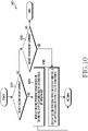
- FIG. 7 is a detailed operation sequence of an electronic device (e.g., the electronic device 10) for analyzing at least one object displayed in a first preview image, and selecting at least one camera based on an analysis result according to an embodiment of the present invention.
- FIG. 8 illustrates an example in which an electronic device (e.g., the electronic device 10) analyzes at least one object displayed in a first preview image according to an embodiment of the present invention.
- FIG. 7 and FIG. 8 may be described with reference to the configurations of the electronic device 10 of FIG. 1 through FIG. 5 .
- Operations disclosed in FIG. 7 may be detailed operations of operations 620 and 630 disclosed in FIG. 6 .
- the operations disclosed in FIG. 7 may be performed if the first preview image is the preview image corresponding to the front camera (e.g., the first front camera 541).
- the electronic device 10 may identify a face of at least one person.
- the electronic device 10 may identify that the first preview image includes at least one person's face, and determine at least one of the number, shape, size, or region ratio of the face of the at least one person whose presence is identified. For example, referring to FIG. 8 , the electronic device 10 may identify faces 820 and 830 of two persons included in a first preview image 810.
- the electronic device 10 may identify the face of the person (e.g., the face A 820) fully included in the first preview image, or identify the face of the person (e.g., the face B 830) partially included in the first preview image. For example, if the electronic device 10 identifies a specific face fully included in the first preview image, and then a part of the specific face is cut off on the screen of the first preview image, it may identify that the specific face is partially included in the first preview image.
- the electronic device 10 may identify the face of the person (e.g., the face A 820) fully included in the first preview image, or identify the face of the person (e.g., the face B 830) partially included in the first preview image.
- the electronic device 10 may identify the face partially included in the first preview image.
- a part e.g., one eye
- a feature point e.g., an eyebrow, an eye, a nose, an ear
- the electronic device 10 may determine whether the number of the faces of the at least one identified person is equal to or greater than a first threshold.
- the first threshold may be 3. For example, if four persons' faces are included in the first preview image, the electronic device 10 may identify that the number of the identified faces of the at least one person is equal to or greater than the first threshold.
- the electronic device 10 may select the camera (e.g., the third front camera 543) corresponding to the third field of view range, in operation 760.
- the third field of view range may correspond to a field of view range for displaying the preview image in the ultra-wide-angle mode.
- the electronic device 10 may identify whether there is a person's face partially displayed, in operation 730. For example, it may identify whether the at least one person's face identified includes the face of the person whose part is cut off by the margin of the first preview image.
- the electronic device 10 may select the camera corresponding to the third field of view, in operation 760.
- the electronic device 10 may determine whether there is a person face whose distance to a boundary line of the first preview image is equal to or less than a second threshold, in operation 740. For example, the electronic device 10 may determine whether there is a face of a person close to the boundary of the first preview image, among the faces fully displayed. Referring to FIG. 8 , the electronic device 10 may determine a closed curve corresponding to an outline of the person's face 820 fully displayed and a center 815 of the closed curve, and determine distances from the center 815 of the determined closed curve to boundary lines (e.g., a left boundary line, a right boundary line, a lower boundary line, an upper boundary line) of the first preview image.
- boundary lines e.g., a left boundary line, a right boundary line, a lower boundary line, an upper boundary line
- the electronic device 10 may select the camera corresponding to the third field of view range, in operation 760.
- the electronic device 10 may identify whether a ratio of a region occupied by the face of the at least one identified person in the first preview image (e.g., a ratio of the entire region of the first preview image and the region of the at least one person's face identified) is equal to or greater than a third threshold, in operation 750.
- a ratio of a region occupied by the face of the at least one identified person in the first preview image e.g., a ratio of the entire region of the first preview image and the region of the at least one person's face identified
- the electronic device 10 may select the camera corresponding to the third field of view range, in operation 760.
- the electronic device 10 may select the camera (e.g., the second front camera 542) corresponding to the second field of view range, in operation 770.
- the second field of view range may correspond to a relatively narrower field of view range than the third field of view range.
- the second field of view range may correspond to the field of view range for displaying the preview image in the wide-angle mode.
- the electronic device 10 may select the camera to be activated in response to the folding or the unfolding of the electronic device 10, based on the analysis result of the face of the at least one person included in the first preview image.
- the sequence of the plurality of the operations disclosed in FIG. 7 may be exchanged, and some operation may be omitted.
- the electronic device 10 may perform operation 730 before operation 720, may omit operation 750 after conducting operation 740, and may perform operation 770.
- FIG. 9 illustrates an operation sequence of an electronic device (e.g., the electronic device 10) according to an embodiment of the present invention.
- FIG. 9 may be described with reference to the configurations of the electronic device 10 of FIG. 1 through FIG. 5 .
- the camera corresponding to the second field of view range may be selected in operation 770 as aforementioned.
- FIG. 9 describes the operation which may be additionally performed, before the camera corresponding to the second field of view range is selected, if the ratio of the region occupied by the at least one identified person's face in the first preview image is less than the third threshold.
- the electronic device 10 may identify that the electronic device 10 has moved in a first direction, and then moved in a second direction which is opposite to the first direction, in operation 910. Specifically, while the first preview image is displayed, the electronic device 10 may identify whether the electronic device 10 has moved in the first direction, and then moved in the second direction within a designated time.
- the electronic device 10 may also identify whether the electronic device 10 has moved in the first direction at a first speed, and then moved in the second direction at a second speed within the designated time.
- the second direction may be an opposite direction (z+ direction) to the direction of gravity.
- the first direction may be the y+ direction perpendicular to the z and x axes
- the second direction may be y-direction.
- the movement of the electronic device in the first direction and the second direction is identified in operation 910 to identify whether the user wants the camera shooting with a wider field of view.
- a plurality of subjects e.g., a plurality of persons
- some of the subjects may not be included in the screen frequently.
- the electronic device 10 is moved in a specific direction (e.g., the first direction) to include the some subject in the screen, part of the other subject included in the screen before the movement may not be included in the screen.
- the user generally moves the electronic device 10 in the opposite direction (e.g., the second direction) again, and as a result, the electronic device 10 may perform operation 760 based on determination that the electronic device is moved in the first direction and then moved in the second direction, in operation 910.
- the electronic device 10 may select the camera corresponding to the third field of view range in operation 760. For example, if the electronic device 10 is moved in the first direction and then in the second direction, it may be determined that it is impossible to fulfill the wider field of view shooting as desired by the user with the currently activated camera and display. Hence, the electronic device 10 may select the camera (e.g., the third front camera 543) corresponding to the third field of view range, which is the relatively wide field of view, based on the determination that the user wants the camera shooting with the wider field of view.
- the camera e.g., the third front camera 543
- the electronic device 10 may select the camera corresponding to the second field of view range. For example, if not identifying that the electronic device 10 is moved in the first direction and then in the second direction (NO in operation 910), the electronic device 10 may select the second front camera 542 corresponding to the second field of view range which is the narrower field of view range than the third field of view range.
- operation 910 is performed after operation 750 is conducted, but it may be performed between any one of operation 710 and operation 720, operation 720 and operation 730, operation 730 and operation 740, and operation 740 and operation 750.
- FIG. 10 illustrates a detailed operation sequence of an electronic device (e.g., the electronic device 10) for displaying a second preview image corresponding to a selected camera according to an embodiment of the present invention.
- FIG. 10 may be described with reference to the configurations of the electronic device 10 of FIG. 1 through FIG. 5 .
- the operations disclosed in FIG. 10 may be detailed operations of operation 650 disclosed in FIG. 6 .
- the electronic device 10 may identify whether the second front camera 542 is selected, in operation 1010.
- the electronic device 10 may display the second preview image based on a second field of view included in the second field of view range in operation 1020. For example, if the second field of view range corresponds to 60 degrees through 90 degrees, the electronic device 10 may display the second preview image on the second display 552 based on the 75-degree field of view.
- the second field of view range may correspond to the field of view range for displaying the preview image in the wide-angle mode.
- the electronic device 10 may determine whether the third front camera 543 is selected in operation 1030. If the third front camera 543 is not selected (NO in operation 1030), the electronic device 10 may terminate the corresponding algorithm. If the third front camera 543 is selected (YES in operation 1030), the electronic device 10 may display the second preview image based on a third field of view included in the third field of view range, in operation 1040. For example, if the third field of view range corresponds to 90 degrees through 180 degrees, the electronic device may display the second preview image on the second display 552 based on the 120-degree field of view.
- the third field of view range may correspond to the field of view range for displaying the preview image in the ultra-wide-angle mode.
- FIG. 11 illustrates an electronic device 10 according to an embodiment of the present invention.
- FIG. 11A illustrates the electronic device in the folded state
- FIG. 11B illustrates the electronic device in the flat state.
- the electronic device 10 may display a first preview image 1110 on the first display 551.
- the first preview image 1110 may be a preview image of the first front camera 541.
- the first front camera 541 may support the first field of view range or correspond to the first field of view range.
- the electronic device 10 may select at least one camera, based on an analysis result of at least one object included in the first preview image 1110. For example, based on distances between faces of two persons included in the first preview image 1110 and boundary lines of the first preview image 1110, the electronic device 10 may select the third front camera 543 supporting the relatively wider field of view range, among the second front camera 542 and the third front cameras 543.
- the electronic device 10 may detect unfolding. In response to detecting the unfolding, the electronic device 10 may activate the selected third front camera 543, and display a second preview image 1120 corresponding to the activated third front camera 543. Hence, even without an explicit user input, the electronic device 10 may provide the user with the preview image of the camera supporting the wider field of view range, in response to the unfolding of the electronic device 10.
- FIG. 12 is a detailed operation sequence of an electronic device (e.g., the electronic device 10) for analyzing at least one object displayed in a first preview image, and selecting at least one camera based on an analysis result according to an embodiment of the present invention.
- FIG. 12 may be described with reference to the configurations of the electronic device 10 of FIG. 1 through FIG. 5 .
- Operations disclosed in FIG. 12 may be detailed operations of operations 620 and 630 disclosed in FIG. 6 .
- the operations disclosed in FIG. 12 may be performed if the first preview image is a preview image corresponding to the first rear camera 341.
- the electronic device 10 may identify that the first preview image corresponds to a landscape image.
- the electronic device 10 may not identify at least one person's face in the first preview image, or if a size of at least one person's face included in the first preview image is smaller than a reference value, the electronic device 10 may identify that the first preview image corresponds to the landscape image.
- the electronic device 10 may determine a type (e.g., mountain, sea, tree, building) of a main subject (e.g., the largest subject) included in the first preview image, and identify based on the determined object type that the first preview image corresponds to the landscape image.
- a type e.g., mountain, sea, tree, building
- a main subject e.g., the largest subject
- the electronic device 10 may identify whether an arrangement of at least one object included in the first preview image corresponds to at least one pre-designated arrangement.
- the electronic device 10 may determine that it corresponds to at least one pre-designated arrangement.
- the electronic device 10 may determine that it corresponds to at least one pre-designated arrangement.
- the electronic device 10 may determine that it corresponds to at least one pre-designated arrangement. For example, if a horizontal line or a horizon exceeding a designated value is included in the first preview image, the electronic device 10 may determine that it corresponds to at least one predetermined arrangement. As another example, if the first preview image includes trees arranged in a row, and a line connecting top portions of the trees has a specific slope over a specific length, the electronic device 10 may determine that the at least one object included in the first preview image corresponds to at least one pre-designated arrangement.
- the electronic device 10 may select the camera corresponding to the third field of view range in operation 1230. For example, the electronic device 10 may select the third rear camera 343 corresponding to the third field of view range.
- the electronic device 10 may select the camera corresponding to the second field of view range in operation 1240. For example, the electronic device 10 may select the first rear camera 341 corresponding to the first preview image as it is.
- FIG. 13 illustrates an electronic device 10 according to embodiments of the present invention.
- FIG. 13A illustrates the electronic device of the folded state from various angles
- FIG. 13B illustrates the electronic device of the flat state.
- the electronic device 10 including the first rear camera 341, the second rear camera 342, and the third rear camera 343 may display a preview image 1310 on the first display 551.
- the first preview image 1310 may be a preview image of the first rear camera 341.
- the first rear camera 341 may correspond to the second field of view range.
- the electronic device 10 may display a first indicator 1330 indicating which camera corresponds to the currently displayed preview image, by overlapping at least a part of the first preview image 1310, on the first display 551.
- the first indicator 1330 may include objects (a first object 1331 corresponding to the first rear camera 341, a second object 1332 corresponding to the second rear camera 342, and a third object 1333 corresponding to the third rear camera 343) indicating the activation or deactivation state of the first rear camera 341, the second rear camera 342, and the third rear camera 343.
- the first object 1331 corresponding to the first rear camera 341 may be displayed to be distinguished (e.g., color, shape, and shade) from the second object 1332 corresponding to the second rear camera 342, and the third object 1333 corresponding to the third rear camera 343.
- the electronic device 10 may identify that the first preview image 1310 corresponds to a landscape image. Based on determining that an object (a road 1311) included in the first preview image 1310 is arranged bilaterally symmetrically, the electronic device 10 may identify that the arrangement of the at least one object included in the first preview image 1310 corresponds to at least one pre-designated arrangement. Hence, the electronic device 10 may select the third rear camera 343 corresponding to the relatively wider field of view range.
- the electronic device 10 may display a second preview image 1320 on the second display 552.
- the second preview image 1320 may be a preview image of the selected third rear camera 343.
- the third rear camera 343 may correspond to the third field of view range, which is the wider field of view range than the second field of view range.
- the electronic device 10 may display a second indicator 1340 indicating which camera corresponds to the currently displayed preview image, by overlapping at least a part of the second preview image 1320, on the second display 552.
- the second indicator 1340 may include objects (a first object 1341 corresponding to the first rear camera 341, a second object 1342 corresponding to the second rear camera 342, and a third object 1343 corresponding to the third rear camera 343) indicating the activation or deactivation state of the first rear camera 341, the second rear camera 342, and the third rear camera 343, after the unfolding of the electronic device 10.
- the third object 1343 corresponding to the third rear camera 343 may be displayed to be distinguished from the first object 1341 corresponding to the first rear camera, and the second object 1342 corresponding to the second rear camera.
- FIG. 14 illustrates a detailed operation sequence of an electronic device (e.g., the electronic device 10) for outputting a guide notification according to an embodiment of the present invention.
- FIG. 14 may be described with reference to the configurations of the electronic device 10 of FIG. 1 through FIG. 5 .
- the operation disclosed in FIG. 14 may be performed after operation 630 disclosed in FIG. 6 is conducted.
- the electronic device 10 may output a notification for guiding the folding or the unfolding for the photographing with a different field of view.
- the electronic device 10 may output the notification for guiding the unfolding of the electronic device 10 for the photographing with a wider field of view, and the electronic device 10 may output the notification for guiding the folding for the photographing with a narrower field of view.
- the electronic device 10 may display the notification for guiding the unfolding in the form of a pop-up window on the first display 551, or may output to a speaker (e.g., the sound output device 155). In an embodiment, the electronic device 10 may display the notification for guiding the folding in the form of a pop-up window on the second display 552, or may output to the speaker (e.g., the sound output device 155).
- the electronic device 10 may determine whether to output the notification for guiding the folding (or the unfolding).
- the electronic device 10 may determine whether to output the notification for guiding the folding (or the unfolding,) depending on the selected camera. For example, if the selected camera may be used to capture a currently displayed subject even without folding (or unfolding) the electronic device 10, the electronic device 10 may not output the notification for guiding the folding (or the unfolding). As another example, if the camera is not changed, the electronic device 10 may not output the notification for guiding the folding (or the unfolding).
- the electronic device 10 may output the notification for guiding the folding (or the unfolding) at a designated timing. While the first preview image is being displayed, if a time for which a user input for the photographing is not received is longer than a designated time, the electronic device 10 may output the notification for guiding the folding (or the unfolding).
- the electronic device 10 may output the notification for guiding the folding (or the unfolding) for a designated guide time.
- the electronic device 10 may immediately remove the outputted notification.
- FIG. 15 illustrates examples in which an electronic device 10 outputs a guide notification according to an embodiment of the present invention.
- the electronic device 10 may display a first preview image 1510 on the first display 551.
- the first preview image 1510 may correspond to the first front camera 541.
- the first front camera 541 may correspond to the first field of view range.
- the electronic device 10 may select the third front camera 543, based on an analysis result of at least one object included in the first preview image 1510.
- the selected third front camera 543 may be activated, in response to detecting the unfolding of the electronic device 10.
- the electronic device 10 may display an unfolding guide notification 1530 for guiding the unfolding of the electronic device 10 on the first display 551.
- the unfolding guide notification 1530 may include a plurality of objects. If the electronic device is unfolded, the plurality of the objects may correspond to a plurality of cameras respectively which may be used to capture a currently displayed subject. For example, a first object 1531 corresponding to the second front camera 542, a second object 1532 corresponding to the third front camera 543, and a third object 1533 corresponding to the fourth front camera (not shown) may be included in the unfolding guide notification 1530.
- the first object 1531, the second object 1532, and the third object 1533 each may include an indication for indicating the performance or the field of view range of its corresponding camera, and the photographing mode.
- the first object 1531 may include a text object "wide” indicating the field of view range supported by the corresponding second front camera 542.
- the second object 1532 may include a text object "ultra wide” indicating the field of view range supported by the corresponding third front camera 543.
- the third object 1533 may include a text object "tele” indicating the field of view range supported by the corresponding first front camera 541.
- the object corresponding to the camera selected based on the analysis result of the at least one object included in the first preview image 1510 may be displayed to be distinguished from the other objects.
- the electronic device 10 may display the second object 1532 corresponding to the third front camera 543, among the objects included in the unfolding guide notification 1530, to be distinguished from the other objects.
- the electronic device 10 may induce user selection for the second object 1532, by displaying the second object 1532 to be distinguished from the other objects.
- the electronic device 10 may receive a user input to the unfolding guide notification 1530.
- the electronic device 10 may receive a user input to the second object 1532, included in the unfolding guide notification 1530, displayed to be distinguished from the other objects.
- the electronic device 10 may receive a user input to an object (e.g., the first object 1531) different from the second object 1532.
- the electronic device 10 may remove the displayed unfolding guide notification 1530.
- the electronic device 10 may display a second preview image 1520 on the second display 552.
- the second preview image 1520 may be a preview image of a camera (e.g., the third front camera 543) corresponding to an object (e.g., the second object 1532) for which the user input is received.
- the third front camera 543 may support the third field of view range which is the field of view range for displaying the preview image in the ultra-wide-angle mode, and the electronic device 10 may display the second preview image 1520 based on a specific field of view included in the third field of view range.
- the electronic device 10 may display a field of view switching menu 1540.
- the field of view switching menu 1540 may indicate that the second preview image 1520 is currently displayed based on the ultra-wide-angle mode.
- the field of view switching menu 1540 may further include icons for displaying the preview image at the field of view corresponding to the wide-angle mode or the telephoto mode. For example, if the icon for displaying the preview image at the field of view corresponding to the wide-angle mode is selected in the field of view switching menu 1540, the electronic device 10 may activate the second front camera 542, and display a preview image of the second front camera 542 on the second display 552.
- FIG. 16 illustrates examples in which an electronic device 10 outputs a guide notification according to an embodiment of the present invention.
- FIG. 16A illustrates the electronic device 10 of the folded state from various angles
- FIG. 16B illustrates the electronic device 10 of the flat state.
- the electronic device 10 may display a first preview image 1610 on the first display 551.
- the first preview image 1610 may be a preview image of the first rear camera 341.
- the first rear camera 341 may correspond to the second field of view range.
- the electronic device 10 may select the third rear camera 343, based on an analysis result of at least one object included in the first preview image 1610.
- the third rear camera 343 may correspond to the third field of view range which is the wider field of view range than the second field of view range.
- the electronic device 10 may display a first indicator 1630 indicating which camera corresponds to the currently displayed preview image, by overlapping at least a part of the first preview image 1610.
- the first indicator 1630 may include objects (a first object 1631 corresponding to the first rear camera 341, a second object 1632 corresponding to the second rear camera 342, and a third object 1633 corresponding to the third rear camera 343) indicating the activation or deactivation state of the first rear camera 341, the second rear camera 342, and the third rear camera 343. Since the preview image currently displayed on the first display 551 corresponds to the first rear camera 341, the first object 1631 corresponding to the first rear camera 341 may be displayed to be distinguished (e.g., color, shape, and shade) from the second object 1632 corresponding to the second rear camera 342, and the third object 1633 corresponding to the third rear camera 343.
- objects a first object 1631 corresponding to the first rear camera 341, a second object 1632 corresponding to the second rear camera 342, and a third object 1633 corresponding to the third rear camera 343.
- the electronic device may display an unfolding guide notification 1650.
- the unfolding guide notification 1650 may include a text or image object for suggesting the unfolding of the electronic device 10 to capture a whole subject.
- the electronic device 10 may provide the user with field of view information which may be used to capture the subject after the electronic device 10 is unfolded.
- the unfolding guide notification 1650 may include information of the selected camera.
- the unfolding guide notification 1650 may include a text object such as "When unfolded to capture the whole subject, it switches to the ultra-wide-angle shooting mode".
- the electronic device 10 may display a second preview image 1620 on the second display 552.
- the second preview image 1620 may be a preview image of the selected third rear camera 343.
- the electronic device 10 may display a second indicator 1640 indicating which camera corresponds to the currently displayed preview image, by overlapping at least a part of the second preview image 1620.
- the second indicator 1640 may include objects (a first object 1641 corresponding to the first rear camera 341, a second object 1642 corresponding to the second rear camera 342, and a third object 1643 corresponding to the third rear camera 343) indicating the activation or deactivation state of the first rear camera 341, the second rear camera 342, and the third rear camera 343.
- FIG. 17 illustrates a detailed operation sequence of an electronic device (e.g., the electronic device 10) for outputting a guide notification according to an embodiment of the present invention.
- an electronic device e.g., the electronic device 10.
- the operations disclosed in FIG. 17 may be performed if the first preview image and the second preview image correspond to the landscape image.
- the operations disclosed in FIG. 17 may be performed, if at least one object included in the second preview image corresponds to at least one pre-designated arrangement (e.g., the arrangement illustrated in FIG. 12 ).
- the electronic device 10 may output a notification for guiding the movement of the electronic device 10.
- the electronic device 10 may output the notification guiding the electronic device 10 to move in a designated direction or rotate in order to create a panorama photo.
- the electronic device 10 may output a notification 1850 which suggests a panorama photographing mode for complete landscape photographing.
- the electronic device 10 may detect movement of the electronic device, in operation 1720.
- the electronic device 10 may detect the movement (or the rotation) of the electronic device suggested in operation 1710.
- the electronic device 10 may obtain image information for creating the panorama photo based on camera movement caused by the detected movement of the electronic device 10.
- the acquired image information may be used to create the panorama photo in operation 660.
- FIG. 18 illustrates examples in which an electronic device 10 outputs a guide notification according to an embodiment of the present invention.
- FIG. 18A illustrates the electronic device 10 of the flat state of a first viewpoint
- FIG. 18B illustrates the electronic device 10 of the flat state of a second viewpoint.
- the electronic device 10 may select the third rear camera (e.g., the third rear camera 343) based on an analysis result of at least one object included in a first preview image 1821.
- the third rear camera e.g., the third rear camera 343
- the electronic device 10 may display a second indicator 1840 indicating which camera corresponds to the currently displayed preview image, by overlapping at least a part of the first preview image 1821.
- the second indicator 1840 may include objects (a first object 1841 corresponding to the first rear camera 341, a second object 1842 corresponding to the second rear camera 342, and a third object 1843 corresponding to the third rear camera 343) indicating the activation or deactivation state of the first rear camera (e.g., the first rear camera 34), the second rear camera (e.g., the second rear camera 342), and the third rear camera 343. Since the preview image currently displayed on the first display 551 corresponds to the third rear camera 343, the third object 1843 may be displayed to be distinguished (e.g., color, shape, and shade) from the first object 1841 and the second object 1842.
- the electronic device 10 may determine the type (e.g., mountain, tree) of the main subject (e.g., the largest subject) included in the first preview image 1821, and identify that the first preview image 1821 corresponds to the landscape image based on the determined object type.
- the type e.g., mountain, tree
- the main subject e.g., the largest subject
- a panorama guide notification 1850 for the panorama photographing may be displayed.
- the panorama guide notification 1850 may include a text or image object suggesting movement of the electronic device 10 to capture a full landscape.
- the electronic device 10 may provide the user with panorama photographing information of the electronic device 10, by displaying the panorama guide notification 1850 to overlap the second preview image 1825.
- FIG. 19 illustrates an operation sequence of an electronic device (e.g., the electronic device 10) according to an embodiment of the present invention.
- Operations disclosed in FIG. 19 may be carried out by the electronic device 10, under the control of the processor 120 of FIG. 5 . Hereafter, it is described that the electronic device 10 performs the operations disclosed in FIG. 19 .
- Operations 1910, 1920, 1940, and 1950 are substantially the same as operations 610, 640, 650, and 660 disclosed in FIG. 6 , and accordingly their detailed descriptions shall be omitted.
- the electronic device 10 may select at least one camera based on at least one of the at least one object analysis result displayed in the first preview image or the user preference information.
- the electronic device 10 may perform the operation of selecting at least one camera, after the folding or the unfolding of the electronic device is detected.
- the electronic device 10 may select at least one camera based on the at least one object analysis result displayed in the first preview image. For example, if the number of faces of persons included in the first preview image is equal to or greater than the first threshold, the electronic device 10 may select the third front camera which supports the relatively wide field of view range, among the second front camera and the third front camera.
- the electronic device 10 may select at least one camera based on the user preference information stored in the memory 130.
- the electronic device 10 may select the second front camera 542, using information of the type of the first preview image (e.g., a portrait photo, a landscape photo), the number of times that the user takes photos of a specific type using the second front camera 542, and the number of times that the user takes photos of a specific type using the third front camera 543.
- information of the type of the first preview image e.g., a portrait photo, a landscape photo
- the electronic device 10 may compare the number of times that the user takes photos using only the second front camera 542, and the number of times that the user takes photos using the second front camera 542 and the fourth front camera at the same time, and select the second front camera 542 and the fourth front camera (not shown) using the comparison result.
- a computer readable recording medium may include a hard disk, a floppy disc, magnetic media (e.g., a magnetic tape), optical storage media (e.g., a compact disk (CD)-read only memory (ROM) or a digital versatile disk (DVD), magnetic-optic media (e.g., a floptical disc)), an internal memory, and so on.
- An instruction may include code created by a compiler or code executable by an interpreter.
- a module or program module may include at least one or more of the aforementioned components, omit some of them, or further include other components. Operations performed by the module, the program, or another component, according to various embodiments may be carried out sequentially, in parallel, repeatedly or heuristically, or at least some operations may be executed in a different order or omitted, or other operations may be added.
Abstract
Description
- • The present disclosure relates to an electronic device for providing a preview image of a camera in response to folding or unfolding of a foldable device including a plurality of cameras and an operating method thereof.
- • With recent development of digital technology, electronic devices of various types such as a mobile communication terminal, a smart phone, a tablet personal computer (PC), a personal digital assistant (PDA), an electronic notebook, a notebook or a wearable device are widely used. The electronic device has reached a mobile convergence stage embracing functions of other devices. For example, the electronic device may provide call functions such as a voice call and a video call, message transmission/reception functions such as a short message service (SMS)/multimedia message service (MMS) and e-mail, an electronic notebook function, a photographing function, a broadcast playback function, a video playback function, a music playback function, an Internet function, a messenger function, a game function or a social networking service (SNS) function.
- • In addition, the electronic device may include a plurality of cameras including at least one front camera and at least one rear camera, to satisfy various user needs related to the photographing function.
- • Since such an electronic device includes one display having a fixed size, fields of view of the plurality of the cameras are mostly fixed. Hence, there is inconvenience in having to provide additional equipment such as a selfie stick to capture more people or a wider landscape. However, even if the additional equipment is provided, the camera shooting itself is uneasy, a subject size reduces compared to the fixed display size as the electronic device gets farther away, and accordingly it is difficult to accurately identify a state of the subject while capturing it.
- • In addition, such an electronic device may be implemented to be foldable. That is, the electronic device may be folding based on a center region. The electronic device implemented to be foldable (hereafter, a foldable electronic device) may include more available surfaces, than an electronic device which is not. Thus, the foldable electronic device may include a plurality of cameras and a plurality of displays having different functions and performances. However, in photographing using the plurality of the cameras and the plurality of the displays, even if the camera to be used for the photographing or the display for displaying a camera preview image is changed, parameters related to the photographing (e.g., a field of view, a resolution, an aspect ratio) are maintained the same. That is, there is inconvenience in that a user needs to manually set (or change) the parameters related to the photographing. Hence, it is demanded to provide the user with various services related to the photographing using folding (or unfolding) of the foldable electronic device as a triggering event, even if there is no explicit user input for setting (or changing) a function or an effect related to the photographing.
- • A foldable electronic device according to an embodiment of the present invention may include a plurality of cameras, at least one display, at least one processor operatively connected with the plurality of the cameras and the at least one display, and at least one memory operatively connected with the at least one processor, and the at least one memory may store instructions, when executed, causing the at least one processor to, while a first preview image corresponding to a first camera among the plurality of the cameras is displayed on the at least one display, select at least one other camera, based on an analysis result of at least one object included in the first preview image, in response to detecting folding or unfolding of the electronic device, display a second preview image corresponding to the selected at least one camera, and obtain a captured image based on the displayed second preview image.
- • An operating method of a foldable electronic device according to an embodiment of the present invention may include, while a first preview image corresponding to a first camera among a plurality of cameras of the electronic device is displayed on at least one display of the electronic device, selecting at least one other camera of the electronic device, based on an analysis result of at least one object included in the first preview image, in response to detecting folding or unfolding of the electronic device, displaying a second preview image corresponding to the selected at least one camera, and obtaining a captured image based on the displayed second preview image.
- • A foldable electronic device according to an embodiment of the present invention may, in a camera preview state, change setting related to preview image displaying (e.g., a camera providing a preview image, or an aspect ratio), in response to folding and/or unfolding of the foldable electronic device. Even if there is no user's explicit input, the foldable electronic device according to an embodiment of the present invention may select a camera for providing the preview image, and provide a new preview image according to an optimal setting value according to a use situation of the foldable electronic device, in response to the folding and/or the unfolding of the foldable electronic device. Thus, a continuous camera shooting environment appropriate for the user's shooting situation may be provided.
-
- •
FIG. 1 is a block diagram of an electronic device in a network environment, according to an embodiment. - •
FIG. 2 is a diagram illustrating a flat state of an electronic device according to an embodiment. - •
FIG. 3 is a diagram illustrating a folded state of an electronic device according to an embodiment. - •
FIG. 4 is an exploded perspective view of an electronic device according to an embodiment. - •
FIG. 5 is a block diagram of an electronic device according to an embodiment. - •
FIG. 6 illustrates an operation sequence of an electronic device according to an embodiment. - •
FIG. 7 is a detailed operation sequence of an electronic device for analyzing at least one object displayed in a first preview image, and selecting at least one camera based on an analysis result according to an embodiment. - •
FIG. 8 illustrates an example in which an electronic device analyzes at least one object displayed in a first preview image according to an embodiment. - •
FIG. 9 illustrates an operation sequence of an electronic device according to an embodiment. - •
FIG. 10 illustrates a detailed operation sequence of an electronic device for displaying a second preview image corresponding to a selected camera according to an embodiment. - •
FIG. 11 illustrates an electronic device according to an embodiment. - •
FIG. 12 is a detailed operation sequence of an electronic device for analyzing at least one object displayed in a first preview image, and selecting at least one camera based on an analysis result according to an embodiment. - •
FIG. 13 illustrates an electronic device according to an embodiment. - •
FIG. 14 illustrates a detailed operation sequence of an electronic device for outputting a guide notification according to an embodiment. - •
FIG. 15 illustrates examples in which an electronic device outputs a guide notification according to an embodiment. - •
FIG. 16 illustrates examples in which an electronic device outputs a guide notification according to an embodiment. - •
FIG. 17 illustrates a detailed operation sequence of an electronic device for outputting a guide notification according to an embodiment. - •
FIG. 18 illustrates examples in which an electronic device outputs a guide notification according to an embodiment. - •
FIG. 19 illustrates an operation sequence of an electronic device according to an embodiment. - • With regard to descriptions of the drawings, the same or similar reference numerals may be used for the same or similar components.
- •
Fig. 1 is a block diagram illustrating anelectronic device 10 in anetwork environment 1 according to various embodiments. Referring toFig. 1 , theelectronic device 10 in thenetwork environment 1 may communicate with anelectronic device 12 via a first network 198 (e.g., a short-range wireless communication network), or anelectronic device 14 or aserver 18 via a second network 199 (e.g., a long-range wireless communication network). According to an embodiment, theelectronic device 10 may communicate with theelectronic device 14 via theserver 18. According to an embodiment, theelectronic device 10 may include aprocessor 120,memory 130, aninput device 150, asound output device 155, adisplay device 160, anaudio module 170, asensor module 176, aninterface 177, ahaptic module 179, acamera module 180, apower management module 188, abattery 189, acommunication module 190, a subscriber identification module (SIM) 196, or anantenna module 197. In various embodiments, at least one (e.g., thedisplay device 160 or the camera module 180) of the components may be omitted from theelectronic device 10, or one or more other components may be added in theelectronic device 10. In various embodiments, some of the components may be implemented as single integrated circuitry. For example, the sensor module 176 (e.g., a fingerprint sensor, an iris sensor, or an illuminance sensor) may be implemented as embedded in the display device 160 (e.g., a display). - • The
processor 120 may execute, for example, software (e.g., a program 141) to control at least one other component (e.g., a hardware or software component) of theelectronic device 10 coupled with theprocessor 120, and may perform various data processing or computation. According to an embodiment, as at least part of the data processing or computation, theprocessor 120 may load a command or data received from another component (e.g., thesensor module 176 or the communication module 190) in volatile memory 132, process the command or the data stored in the volatile memory 132, and store resulting data innon-volatile memory 134. According to an embodiment, theprocessor 120 may include a main processor 121 (e.g., a central processing unit (CPU) or an application processor (AP)), and an auxiliary processor 123 (e.g., a graphics processing unit (GPU), an image signal processor (ISP), a sensor hub processor, or a communication processor (CP)) that is operable independently from, or in conjunction with, themain processor 121. Additionally or alternatively, theauxiliary processor 123 may be adapted to consume less power than themain processor 121, or to be specific to a specified function. Theauxiliary processor 123 may be implemented as separate from, or as part of themain processor 121. - • The
auxiliary processor 123 may control at least some of functions or states related to at least one component (e.g., thedisplay device 160, thesensor module 176, or the communication module 190) among the components of theelectronic device 10, instead of themain processor 121 while themain processor 121 is in an inactive (e.g., sleep) state, or together with themain processor 121 while themain processor 121 is in an active state (e.g., executing an application). According to an embodiment, the auxiliary processor 123 (e.g., an image signal processor or a communication processor) may be implemented as part of another component (e.g., thecamera module 180 or the communication module 190) functionally related to theauxiliary processor 123. - • The
memory 130 may store various data used by at least one component (e.g., theprocessor 120 or the sensor module 176) of theelectronic device 10. The various data may include, for example, software (e.g., the program 141) and input data or output data for a command related thereto. Thememory 130 may include the volatile memory 132 or thenon-volatile memory 134. - • The
program 141 may be stored in thememory 130 as software, and may include, for example, an operating system (OS) 142,middleware 144, or anapplication 146. - • The
input device 150 may receive a command or data to be used by other component (e.g., the processor 120) of theelectronic device 10, from the outside (e.g., a user) of theelectronic device 10. Theinput device 150 may include, for example, a microphone, a mouse, a keyboard, or a digital pen (e.g., a stylus pen). - • The
sound output device 155 may output sound signals to the outside of theelectronic device 10. Thesound output device 155 may include, for example, a speaker or a receiver. The speaker may be used for general purposes, such as playing multimedia or playing record, and the receiver may be used for an incoming calls. According to an embodiment, the receiver may be implemented as separate from, or as part of the speaker. - • The
display device 160 may visually provide information to the outside (e.g., a user) of theelectronic device 10. Thedisplay device 160 may include, for example, a display, a hologram device, or a projector and control circuitry to control a corresponding one of the display, hologram device, and projector. According to an embodiment, thedisplay device 160 may include touch circuitry adapted to detect a touch, or sensor circuitry (e.g., a pressure sensor) adapted to measure the intensity of force incurred by the touch. - • The
audio module 170 may convert a sound into an electrical signal and vice versa. According to an embodiment, theaudio module 170 may obtain the sound via theinput device 150, or output the sound via thesound output device 155 or a headphone of an external electronic device (e.g., an electronic device 12) directly (e.g., wiredly) or wirelessly coupled with theelectronic device 10. - • The
sensor module 176 may detect an operational state (e.g., power or temperature) of theelectronic device 10 or an environmental state (e.g., a state of a user) external to theelectronic device 10, and then generate an electrical signal or data value corresponding to the detected state. According to an embodiment, thesensor module 176 may include, for example, a gesture sensor, a gyro sensor, an atmospheric pressure sensor, a magnetic sensor, an acceleration sensor, a grip sensor, a proximity sensor, a color sensor, an infrared (IR) sensor, a biometric sensor, a temperature sensor, a humidity sensor, or an illuminance sensor. - • The
interface 177 may support one or more specified protocols to be used for theelectronic device 10 to be coupled with the external electronic device (e.g., the electronic device 12) directly (e.g., wiredly) or wirelessly. According to an embodiment, theinterface 177 may include, for example, a high definition multimedia interface (HDMI), a universal serial bus (USB) interface, a secure digital (SD) card interface, or an audio interface. - • A connecting
terminal 178 may include a connector via which theelectronic device 10 may be physically connected with the external electronic device (e.g., the electronic device 12). According to an embodiment, the connectingterminal 178 may include, for example, a HDMI connector, a USB connector, a SD card connector, or an audio connector (e.g., a headphone connector). - • The
haptic module 179 may convert an electrical signal into a mechanical stimulus (e.g., a vibration or a movement) or electrical stimulus which may be recognized by a user via his tactile sensation or kinesthetic sensation. According to an embodiment, thehaptic module 179 may include, for example, a motor, a piezoelectric element, or an electric stimulator. - • The
camera module 180 may capture a still image or moving images. According to an embodiment, thecamera module 180 may include one or more lenses, image sensors, image signal processors, or flashes. - • The
power management module 188 may manage power supplied to theelectronic device 10. According to an embodiment, thepower management module 188 may be implemented as at least part of, for example, a power management integrated circuit (PMIC). - • The
battery 189 may supply power to at least one component of theelectronic device 10. According to an embodiment, thebattery 189 may include, for example, a primary cell which is not rechargeable, a secondary cell which is rechargeable, or a fuel cell. - • The
communication module 190 may support establishing a direct (e.g., wired) communication channel or a wireless communication channel between theelectronic device 10 and the external electronic device (e.g., theelectronic device 12, theelectronic device 14, or the server 18) and performing communication via the established communication channel. Thecommunication module 190 may include one or more communication processors that are operable independently from the processor 120 (e.g., the application processor (AP)) and supports a direct (e.g., wired) communication or a wireless communication. According to an embodiment, thecommunication module 190 may include a wireless communication module 192 (e.g., a cellular communication module, a short-range wireless communication module, or a global navigation satellite system (GNSS) communication module) or a wired communication module 194 (e.g., a local area network (LAN) communication module or a power line communication (PLC) module). A corresponding one of these communication modules may communicate with the external electronic device via the first network 198 (e.g., a short-range communication network, such as Bluetooth™, wireless-fidelity (Wi-Fi) direct, or infrared data association (IrDA)) or the second network 199 (e.g., a long-range communication network, such as a cellular network, the Internet, or a computer network (e.g., LAN or wide area network (WAN)). These various types of communication modules may be implemented as a single component (e.g., a single chip), or may be implemented as multi components (e.g., multi chips) separate from each other. The wireless communication module 192 may identify and authenticate theelectronic device 10 in a communication network, such as thefirst network 198 or thesecond network 199, using subscriber information (e.g., international mobile subscriber identity (IMSI)) stored in thesubscriber identification module 196. - • The
antenna module 197 may transmit or receive a signal or power to or from the outside (e.g., the external electronic device) of theelectronic device 10. According to an embodiment, theantenna module 197 may include an antenna including a radiating element including a conductive material or a conductive pattern formed in or on a substrate (e.g., PCB). According to an embodiment, theantenna module 197 may include a plurality of antennas. In such a case, at least one antenna appropriate for a communication scheme used in the communication network, such as thefirst network 198 or thesecond network 199, may be selected, for example, by the communication module 190 (e.g., the wireless communication module 192) from the plurality of antennas. The signal or the power may then be transmitted or received between thecommunication module 190 and the external electronic device via the selected at least one antenna. According to an embodiment, another component (e.g., a radio frequency integrated circuit (RFIC)) other than the radiating element may be additionally formed as part of theantenna module 197. - • At least some of the above-described components may be coupled mutually and communicate signals (e.g., commands or data) therebetween via an inter-peripheral communication scheme (e.g., a bus, general purpose input and output (GPIO), serial peripheral interface (SPI), or mobile industry processor interface (MIPI)).
- • According to an embodiment, commands or data may be transmitted or received between the
electronic device 10 and the externalelectronic device 14 via theserver 18 coupled with thesecond network 199. Each of theelectronic devices electronic device 10. According to an embodiment, all or some of operations to be executed at theelectronic device 10 may be executed at one or more of the externalelectronic devices electronic device 10 should perform a function or a service automatically, or in response to a request from a user or another device, theelectronic device 10, instead of, or in addition to, executing the function or the service, may request the one or more external electronic devices to perform at least part of the function or the service. The one or more external electronic devices receiving the request may perform the at least part of the function or the service requested, or an additional function or an additional service related to the request, and transfer an outcome of the performing to theelectronic device 10. Theelectronic device 10 may provide the outcome, with or without further processing of the outcome, as at least part of a reply to the request. To that end, a cloud computing, distributed computing, or client-server computing technology may be used, for example. - • The electronic device according to various embodiments may be one of various types of electronic devices. The electronic devices may include, for example, a portable communication device (e.g., a smartphone), a computer device, a portable multimedia device, a portable medical device, a camera, a wearable device, a home appliance, or the like. According to an embodiment of the disclosure, the electronic devices are not limited to those described above.
- • It should be appreciated that various embodiments of the present disclosure and the terms used therein are not intended to limit the technological features set forth herein to particular embodiments and include various changes, equivalents, or replacements for a corresponding embodiment. With regard to the description of the drawings, similar reference numerals may be used to refer to similar or related elements. It is to be understood that a singular form of a noun corresponding to an item may include one or more of the things, unless the relevant context clearly indicates otherwise. As used herein, each of such phrases as "A or B," "at least one of A and B," "at least one of A or B," "A, B, or C," "at least one of A, B, and C," and "at least one of A, B, or C," may include any one of, or all possible combinations of the items enumerated together in a corresponding one of the phrases. As used herein, such terms as "1st" and "2nd," or "first" and "second" may be used to simply distinguish a corresponding component from another, and does not limit the components in other aspect (e.g., importance or order). It is to be understood that if an element (e.g., a first element) is referred to, with or without the term "operatively" or "communicatively", as "coupled with," coupled to," "connected with," " or "connected to" another element (e.g., a second element), it means that the element may be coupled with the other element directly (e.g., wiredly), wirelessly, or via a third element.
- • As used herein, the term "module" may include a unit implemented in hardware, software, or firmware, and may interchangeably be used with other terms, for example, "logic," "logic block," "part," or "circuitry". A module may be a single integral component, or a minimum unit or part thereof, adapted to perform one or more functions. For example, according to an embodiment, the module may be implemented in a form of an application-specific integrated circuit (ASIC).
- • Various embodiments as set forth herein may be implemented as software (e.g., the program 141) including one or more instructions that are stored in a storage medium (e.g.,
internal memory 136 or external memory 138) that is readable by a machine (e.g., the electronic device 10) . For example, a processor(e.g., the processor 120) of the machine (e.g., the electronic device 10) may invoke at least one of the one or more instructions stored in the storage medium, and execute it, with or without using one or more other components under the control of the processor. This allows the machine to be operated to perform at least one function according to the at least one instruction invoked. The one or more instructions may include a code generated by a complier or a code executable by an interpreter. The machine-readable storage medium may be provided in the form of a non-transitory storage medium. Wherein, the "non-transitory" storage medium is a tangible device, and may not include a signal (e.g., an electromagnetic wave), but this term does not differentiate between where data is semi-permanently stored in the storage medium and where the data is temporarily stored in the storage medium. - • According to an embodiment, a method according to various embodiments of the disclosure may be included and provided in a computer program product. The computer program product may be traded as a product between a seller and a buyer. The computer program product may be distributed in the form of a machine-readable storage medium (e.g., compact disc read only memory (CD-ROM)), or be distributed (e.g., downloaded or uploaded) online via an application store (e.g., PlayStore™), or between two user devices (e.g., smart phones) directly. If distributed online, at least part of the computer program product may be temporarily generated or at least temporarily stored in the machine-readable storage medium, such as memory of the manufacturer's server, a server of the application store, or a relay server.
- • According to various embodiments, each component (e.g., a module or a program) of the above-described components may include a single entity or multiple entities. According to various embodiments, one or more of the above-described components may be omitted, or one or more other components may be added. Alternatively or additionally, a plurality of components (e.g., modules or programs) may be integrated into a single component. In such a case, according to various embodiments, the integrated component may still perform one or more functions of each of the plurality of components in the same or similar manner as they are performed by a corresponding one of the plurality of components before the integration. According to various embodiments, operations performed by the module, the program, or another component may be carried out sequentially, in parallel, repeatedly, or heuristically, or one or more of the operations may be executed in a different order or omitted, or one or more other operations may be added.
- • Referring to
FIG. 2 andFIG. 3 , in an embodiment, anelectronic device 10 may include afoldable housing 500, ahinge cover 530 which covers a foldable portion of thefoldable housing 500, and a flexible or foldable display 552 (hereafter, referred to as a second display) disposed in a space formed by thefoldable housing 500. A surface on which thesecond display 552 is disposed is defined as a first surface or a front surface of theelectronic device 10 in this document. The opposite surface of the front surface is defined as a second surface or a rear surface of theelectronic device 10. Also, a surface surrounding a space between the front surface and the rear surface is defined as a third surface or a side surface of theelectronic device 10. Theelectronic device 10 may correspond to theelectronic device 10 disclosed inFIG. 1 . - • In an embodiment, the
foldable housing 500 may include afirst housing structure 510, asecond housing structure 520 including asensor region 524, a firstrear cover 580, and a secondrear cover 590. Thefoldable housing 500 of theelectronic device 10 is not limited to the shape and the coupling shown inFIGS. 2 and3 , and may be implemented by other shape or combination and/or coupling of components. For example, in an embodiment, thefirst housing structure 510 and the firstrear cover 580 may be integrally formed, and thesecond housing structure 520 and the secondrear cover 590 may be integrally formed. - • In the illustrated embodiment, the
first housing structure 510 and thesecond housing structure 520 may be disposed on both sides based on a folding axis (axis A), and may have a shape which is symmetric on the whole with respect to the folding axis A. Thefirst housing structure 510 and thesecond housing structure 520 may have different angles or distances depending on whether a state of theelectronic device 10 is a flat state, a folded state, or an intermediate state to be explained. In the illustrated embodiment, unlike thefirst housing structure 510, thesecond housing structure 520 may further include thesensor region 524 in which various sensors are disposed. In an embodiment, thesecond housing structure 520 and thefirst housing structure 510 may have a mutually symmetric shape in other regions than thesensor region 524. - • In an embodiment, as shown in
FIG. 2 , thefirst housing structure 510 and thesecond housing structure 520 together may form a recess for accommodating thesecond display 552. In the illustrated embodiment, due to thesensor region 524, the recess may have two or more different widths in a direction perpendicular to the folding axis A. - • For example, the recess may have (1) a first width w1 between a
first portion 510a parallel to the folding axis A in thefirst housing structure 510 and afirst portion 520a formed at an edge of thesensor region 524 in thesecond housing structures 520, and (2) a second width w2 formed by asecond portion 510b of thefirst housing structure 510 and asecond portion 520b not corresponding to thesensor region 524 of thesecond housing structure 520 and parallel to the folding axis A. In this case, the second width w2 may be formed longer than the first width w1. In other words, thefirst portion 510a of thefirst housing structure 510 and thefirst portion 520a of thesecond housing structure 520 having the asymmetric shape may form the first width w1 of the recess, and thesecond portion 510b of thefirst housing structure 510 and thesecond portion 520b of thesecond housing structure 520 having the symmetrical shape may form the second width w2 of the recess. In an embodiment, thefirst portion 520a and thesecond portion 520b of thesecond housing structure 520 may be different in distance from the folding axis A. The width of the recess is not limited to the illustrated example. In various embodiments, the recess may have a plurality of widths based on the shape of thesensor region 524 or the portion having the asymmetric shape of thefirst housing structure 510 and thesecond housing structure 520. - • In an embodiment, at least part of the
first housing structure 510 and thesecond housing structure 520 may be formed of a metallic material or a nonmetallic material having rigidity of a magnitude selected to support thesecond display 552. - • In an embodiment, the
sensor region 524 may be formed to have a designated region adjacent to one corner of thesecond housing structure 520. However, the arrangement, the shape, and the size of thesensor region 524 are not limited to the illustrated example. For example, in another embodiment, thesensor region 524 may be provided at another corner of thesecond housing structure 520 or an arbitrary region between an upper corner and a lower corner. In an embodiment, components for performing various functions imbedded in theelectronic device 10 may be exposed to the front surface of theelectronic device 10 through thesensor region 524, or through one or more openings provided in thesensor region 524. In an embodiment, the components may include various sensors. The sensors may include, for example, at least one of a front camera, a receiver or a proximity sensor. The front camera may correspond to at least one of the secondfront camera 542 and the thirdfront camera 543. In an embodiment, the front camera may further include a fourth front camera (not shown) which is a camera for applying a special effect to a captured image. For example, the fourth front camera (not shown) may be a camera for applying the special effect (e.g., bokeh or out-focusing, telephoto, blur) to the captured image. - • The first
rear cover 580 may be disposed on one side of the folding axis on the rear surface of theelectronic device 10, and may have, for example, a substantially rectangular periphery, and the periphery may be surrounded by thefirst housing structure 510. Similarly, the secondrear cover 590 may be disposed on the other side of the folding axis on the rear surface of theelectronic device 10, and its periphery may be surrounded by thesecond housing structure 520. - • In the illustrated embodiment, the first
rear cover 580 and the secondrear cover 590 may have a substantially symmetrical shape based on the folding axis (the axis A). However, it is merely an example, and the firstrear cover 580 and the secondrear cover 590 do not necessarily have the symmetrical shape. In an embodiment, theelectronic device 10 may include the firstrear cover 580 and the secondrear cover 590 of various shapes. In an embodiment, the firstrear cover 580 may be integrally formed with thefirst housing structure 510, and the secondrear cover 590 may be integrally formed with thesecond housing structure 520. - • In an embodiment, the first
rear cover 580, the secondrear cover 590, thefirst housing structure 510, and thesecond housing structure 520 may form a space for mounting various components (e.g., a printed circuit board, or a battery) of theelectronic device 10. In an embodiment, one or more components may be disposed or visually exposed on the rear surface of theelectronic device 10. For example, at least part of at least one front camera (e.g., the first front camera 541) may be visually exposed in the firstrear cover 580. For example, at least part of thefirst display 551 may be visually exposed through a firstrear region 582 of the firstrear cover 580. In an embodiment, one or more components or sensors may be visually exposed through a secondrear region 592 of the secondrear cover 590. In an embodiment, the sensors may include a proximity sensor and/or a rear camera. The rear camera may correspond to at least one of a firstrear camera 341, a secondrear camera 342, and a thirdrear camera 343. In an embodiment, the rear camera may further include a fourth rear camera (not shown) which is a camera for applying a special effect to the captured image. For example, the fourth rear camera (not shown) may be the camera for applying the special effect (e.g., bokeh or out-focusing, telephoto, blur) to the captured image. - • In an embodiment, the first
front camera 541 may support a first field of view range (or correspond to the first field of view range). The first field of view range may be a field of view range for displaying the preview image in a normal mode. The first field of view range may correspond to a range of 40 degrees through 60 degrees. - • In an embodiment, the second
front camera 542 and the thirdfront camera 543 may correspond to different functions or performances respectively, and may have higher specifications than the firstfront camera 541. For example, the secondfront camera 542 may correspond to a second field of view range (e.g., 60 through 90 degrees) (or support the second field of view range), the thirdfront camera 543 may correspond to a third field of view range (90 degrees through 180 degrees), and the second field of view range and the third field of view range may be wider field of view ranges than the first field of view range corresponding to the firstfront camera 541. The third field of view range may be a wider field of view range than the second field of view range. As another example, the secondfront camera 542 and the thirdfront camera 543 may support a higher resolution than the firstfront camera 541. - • In an embodiment, the first
rear camera 341, the secondrear camera 342, and the thirdrear camera 343 may correspond to different functions or performances. For example, the firstrear camera 341 may correspond to the second field of view range (or support the second field of view range), the secondrear camera 342 may correspond to the first field of view range which is a narrower field of view range than the second field of view range, and the first field of view range may correspond to a telephoto or close-up mode. The thirdrear camera 343 may correspond to a third field of view range which is a wider field of view range than the second field of view range. - • In an embodiment, the second field of view range corresponding to the first
rear camera 341 may correspond to a field of view range for displaying the preview image in a wide-angle mode. - • In an embodiment, the second
rear camera 342 may correspond to a tele camera for magnifying and capturing a subject. - • In an embodiment, the third field of view range corresponding to the third
rear camera 343 may correspond to a field of view range for displaying the preview image in an ultra-wide-angle mode. - • Referring to
FIG. 3 , thehinge cover 530 may be disposed between thefirst housing structure 510 and thesecond housing structure 520, and configured to cover an internal part (e.g., a hinge structure). In an embodiment, thehinge cover 530 may be covered by a part of thefirst housing structure 510 and thesecond housing structure 520, or exposed to outside, depending on the state (the flat state or the folded state) of theelectronic device 10. - • For example, if the
electronic device 10 is in the flat state as shown inFIG. 2 , thehinge cover 530 may be covered by thefirst housing structure 510 and thesecond housing structure 520 not to be exposed. For example, if theelectronic device 10 is in the folded state (e.g., a fully folded state) as shown inFIG. 3 , thehinge cover 530 may be exposed to the outside between thefirst housing structure 510 and thesecond housing structure 520. For example, if thefirst housing structure 510 and thesecond housing structure 520 are folded with a certain angle in an intermediate state, thehinge cover 530 may be partially exposed to the outside between thefirst housing structure 510 and thesecond housing structure 520. However, in this case, the exposed region may be less than the fully folded state. In an embodiment, thehinge cover 530 may include a curved surface. - • The
second display 552 may be disposed on a space formed by thefoldable housing 500. For example, thesecond display 552 may be mounted on a recess formed by thefoldable housing 500, and construct most of the front surface of theelectronic device 10. - • Hence, the front surface of the
electronic device 10 may include thesecond display 552 and some region of thefirst housing structure 510 and some region of thesecond housing structure 520 adjacent to thesecond display 552. The rear surface of theelectronic device 10 may include the firstrear cover 580, some region of thefirst housing structure 510 adjacent to the firstrear cover 580, the secondrear cover 590, and some region of thesecond housing structure 520 adjacent to the secondrear cover 590. - • The
second display 552 may indicate a display in which at least some region may be transformed into a flat surface or a curved surface. In an embodiment, thesecond display 552 may include afolding region 103, afirst region 101 disposed on one side (a left side of thefolding region 103 shown inFIG. 2 ) based on the folding region and asecond region 102 disposed on the other side (a right side of thefolding region 103 shown inFIG. 2 ). - • The region division of the
second display 552 shown inFIG. 2 is merely an example, and thesecond display 552 may be divided into a plurality of (e.g., four or more or two) regions according to its structure or function. For example, the region of thesecond display 552 may be divided by thefolding region 103 or the folding axis (axis A) extending in parallel to the y-axis in the embodiment shown inFIG. 2 , but thesecond display 552 may be divided based on another folding region (e.g., a folding region parallel to the x-axis) or another folding axis (e.g., a folding axis parallel to the x-axis) in an embodiment. - • The
first region 101 and thesecond region 102 may have a shape which is symmetric on the whole based on thefolding region 103. However, unlike thefirst region 101, thesecond region 102 may include a notch which is cut according to the presence of thesensor region 524, but may have the shape symmetrical to thefirst region 101 in other regions. In other words, thefirst region 101 and thesecond region 102 may include the portion having the symmetrical shape, and the having the asymmetrical shape. - • Hereafter, the operations of the
first housing structure 510 and thesecond housing structure 520 and each region of thesecond display 552 are described according to the state of the electronic device 10 (e.g., the flat state and the folded state). - • In an embodiment, if the
electronic device 10 is in the flat state (e.g.,FIG. 2 ), thefirst housing structure 510 and thesecond housing structure 520 may be arranged to make an angle of 180 degrees and face the same direction. A surface of thefirst region 101 and a surface of thesecond region 102 of thesecond display 552 may form 180 degrees, and face the same direction (e.g., the front direction of the electronic device). Thefolding region 103 may form the same plane as thefirst region 101 and thesecond region 102. - • In an embodiment, if the
electronic device 10 is in the folded state (e.g.,FIG. 3 ), thefirst housing structure 510 and thesecond housing structure 520 may be disposed to face each other. The surface of thefirst region 101 and the surface of thesecond region 102 of thesecond display 552 may form a narrow angle (e.g., between 0 degree and 10 degrees), and face each other. At least part of thefolding region 103 may be formed as a curved surface having a designated curvature. - • In an embodiment, if the
electronic device 10 is in the intermediate state, thefirst housing structure 510 and thesecond housing structure 520 may be disposed at a certain angle. The surface of thefirst region 101 and the surface of thesecond region 102 of thesecond display 552 may form an angle which is greater than the folded state and smaller than the flat state. At least part of thefolding region 103 may be formed as a curved surface having a designated curvature, wherein the curvature may be smaller than that of the folded state. - •
FIG. 4 is an exploded perspective view of an electronic device according to various embodiments. - • Referring to
FIG. 4 , in an embodiment, theelectronic device 10 may include adisplay unit 20, abracket assembly 30, asubstrate unit 600, afirst housing structure 510, asecond housing structure 520, a firstrear cover 580 and a secondrear cover 590. In this document, thedisplay unit 20 may be referred to as a display module or a display assembly. - • The
display unit 20 may include thesecond display 552, and one or more plates orlayers 140 on which thesecond display 552 is mounted. In an embodiment, theplate 140 may be disposed between thesecond display 552 and thebracket assembly 30. Thesecond display 552 may be disposed on at least a part of one surface (e.g., an upper surface based onFIG. 3 ) of theplate 140. Theplate 140 may be formed in a shape corresponding to thesecond display 552. For example, some region of theplate 140 may be formed in a shape corresponding to anotch 104 of thesecond display 552. - • The
bracket assembly 30 may include afirst bracket 410, asecond bracket 420, a hinge structure disposed between thefirst bracket 410 and thesecond bracket 420, ahinge cover 530 for covering the hinge structure when viewed from the outside, and a wiring member 430 (e.g., a flexible printed circuit (FPC)) crossing thefirst bracket 410 and thesecond bracket 420. - • In an embodiment, the
bracket assembly 30 may be disposed, between theplate 140 and thesubstrate unit 600. For example, thefirst bracket 410 may be disposed between thefirst region 101 of thesecond display 552 and thefirst substrate 610. Thesecond bracket 420 may be disposed between thesecond region 102 of thesecond display 552 and thesecond substrate 620. - • In an embodiment, the
wiring member 430 and at least part of the hinge structure 300 may be disposed inside thebracket assembly 30. Thewiring member 430 may be disposed in a direction crossing thefirst bracket 410 and the second bracket 420 (e.g., in the x-axis direction). Thewiring member 430 may be disposed in a direction (e.g., the x-axis direction) perpendicular to the folding axis (e.g., the y-axis or the folding axis A ofFIG. 1 ) of thefolding region 103 of theelectronic device 10. - • The
substrate unit 600 may include, as mentioned above, thefirst substrate 610 disposed on thefirst bracket 410 and thesecond substrate 620 disposed on thesecond bracket 420. Thefirst substrate 610 and thesecond substrate 620 may be disposed inside a space formed by thebracket assembly 30, thefirst housing structure 510, thesecond housing structure 520, the firstrear cover 580 and the secondrear cover 590. Components for implementing various functions of theelectronic device 10 may be mounted on thefirst substrate 610 and thesecond substrate 620. - • The
first housing structure 510 and thesecond housing structure 520 may be assembled to be coupled to both sides of thebracket assembly 30 while thedisplay unit 20 is coupled to thebracket assembly 30. As will be described later, thefirst housing structure 510 and thesecond housing structure 520 may slide on both sides of thebracket assembly 30 to be coupled with thebracket assembly 30. - • In an embodiment, the
first housing structure 510 may include a firstrotation support surface 512, and thesecond housing structure 520 may include a secondrotation support surface 522 corresponding to the firstrotation support surface 512. The firstrotation support surface 512 and the secondrotation support surface 522 may include a curved surface corresponding to the curved surface included in thehinge cover 530. - • In an embodiment, if the
electronic device 10 is in the flat state (e.g., the electronic device ofFIG. 1 ), the firstrotation support surface 512 and the secondrotation support surface 522 may cover thehinge cover 530 not to expose thehinge cover 530 to the rear surface of theelectronic device 10 or to expose minimum. Meanwhile, if theelectronic device 10 is in the folded state (e.g., the electronic device ofFIG. 2 ), the firstrotation support surface 512 and the secondrotation support surface 522 may rotate along the curved surface included in thehinge cover 530 to expose thehinge cover 530 maximum to the rear surface of theelectronic device 10. - •
FIG. 5 is a block diagram of anelectronic device 10 according to embodiments of the present invention. - • Referring to
FIG. 5 , theelectronic device 10 may include aprocessor 120, acommunication module 190, amemory 130, aninput module 150, afirst display 551, asecond display 552, and a first through N-th cameras 561 through 569. In an embodiment, N may be a natural number equal to or greater than 3. - • In an embodiment, the
processor 120 may control at least one component included in theelectronic device 10. For example, theprocessor 120 may control thefirst display 551, to display a first preview image corresponding to the first camera 561. For example, theprocessor 120 may analyze at least one object included in the first preview image. - • In an embodiment, the
processor 120 may include animage analysis module 525 and acamera module 526. In an embodiment, theprocessor 120 may execute theimage analysis module 525 and thecamera module 526. In an embodiment, theprocessor 120 may control at least one component included in theelectronic device 10 through theimage analysis module 525 and thecamera module 526. In an embodiment, theimage analysis module 525 and thecamera module 526 may be implemented as a physical circuit, or as a software program. - • In an embodiment, the
image analysis module 525 may analyze at least one object included in the preview image (e.g., the first preview image) displayed on the display (e.g., the first display 551). In an embodiment, in analyzing at least one object, theimage analysis module 525 may determine characteristic information (e.g., size, color, shape, shadow, geometric characteristics, motion information, or movement direction information) of at least one object. In an embodiment, in analyzing at least one object, theimage analysis module 525 may determine a type (e.g., a person, an animal, a building, or a food) of the at least one object. The characteristic information of the at least one object may be used to determine the type of the at least one object. - • In an embodiment, object analysis result information, which is generated at the
image analysis module 525, may be provided to thecamera module 526. - • In an embodiment, the
camera module 526 may process camera preview image data input from the first through N-th cameras 561 through 569. For example, thecamera module 526 may forward the first preview image data input from the first camera 561 to theimage analysis module 525, or receive the object analysis result information from theimage analysis module 525. For example, thecamera module 526 may control thefirst display 551 corresponding to the first camera 561, to display the first preview image input from the first camera 561. - • In an embodiment, based on the object analysis result information received from the
image analysis module 525, thecamera module 526 may select at least one camera (e.g., the second camera 562) to be activated in response to the folding and/or the unfolding of theelectronic device 10. In an embodiment, thecamera module 526 may forward the object analysis result information (or, information generated by processing the object analysis result information) received from theimage analysis module 525, to the at least one camera selected. In an embodiment, if a designated condition is satisfied, thecamera module 526 may provide the information to the at least one selected camera. In an embodiment, the designated condition may be activation of the at least one selected camera (e.g., the second camera 562). In an embodiment, the designated condition may be detection of the folding, or detection of the unfolding of theelectronic device 10. In an embodiment, thecamera module 526 may forward the object analysis result information received from theimage analysis module 525, or the information generated by processing the object analysis result information, to the at least one selected camera, if activating the at least one selected camera (e.g., the second camera 562) (e.g., if detecting the folding and/or the unfolding of the electronic device 10). At least one camera activated may recognize at least one subject, using the information from thecamera module 526. At least one camera activated may recognize at least one subject faster than not using the information, by use of the information from thecamera module 526. - • In an embodiment, the first through the N-th cameras 561 through 569 may embrace a plurality of cameras included in the
electronic device 10. For example, the first camera 561 may correspond to the firstfront camera 541 disclosed inFIG. 2 , and thesecond camera 562 and a third camera (not shown) may correspond to the secondfront camera 542 and the thirdfront camera 543 respectively disclosed inFIG. 2 . However, this is only an example, and the first camera 561, thesecond camera 562, and the third camera (not shown) may correspond to the firstrear camera 341, the secondrear camera 342, and the thirdrear camera 343 respectively shown inFIG. 3 . - • In an embodiment, at least one camera (e.g., the first camera 561) among the first through N-th cameras 561 through 569 may correspond to the
first display 551, and at least one another camera (e.g., the second camera 561, and the third camera (not shown)) may correspond to thesecond display 552. For example, a preview image of the first camera 561 may be displayed on thefirst display 551, and a preview image of thesecond camera 562 or the third camera (not shown) may be displayed on thesecond display 552. - • In an embodiment, the first through N-th cameras 561 through 569 may support different field of view ranges. However, this is only an example, and at least two cameras of the first through N-th cameras 561 through 569 may support the same field of view range.
- • In an embodiment, the first camera 561 may support a first field of view range. In an embodiment, the
second camera 562 may support a second field of view range. In an embodiment, the third camera (not shown) may support a third field of view range. - • In an embodiment, the first field of view range may be a view angle range for displaying the preview image in the normal mode. In an embodiment, the second field of view range may be a view angle range for displaying the preview image in the wide-angle mode. In an embodiment, the third field of view range may be a view angle range for displaying the preview image in the ultra-wide-angle mode. In an embodiment, the first field of view range may have a range of 40 through 60 degrees (°). In an embodiment, the second field of view range may have a range of 60 to 90 degrees (°). In an embodiment, the third field of view range may have a range of 90 to 180 degrees (°).
- • In an embodiment, the first through N-th cameras 561 through 569 may have different resolutions. However, this is only an example, and at least two cameras of the first through N-th cameras 561 through 569 may have the same resolution.
- • In an embodiment, the
first display 551 and thesecond display 552 may display content. For example, an application execution screen, an image (e.g., the preview image of the camera), a video, a call/message notification, and so on may be displayed. - • In an embodiment, the
first display 551 may have a vertical length longer than a horizontal length. Hence, even if a preview image corresponding to the same camera is displayed based on an aspect ratio in which the horizontal length is longer than the vertical length, the margin may increase compared to the opposite case. - • In an embodiment, the
second display 552 may have the horizontal length longer than the vertical length. Hence, even if a preview image corresponding to the same camera is displayed based on an aspect ratio in which the vertical length is longer than the horizontal length, the margin may increase compared to the opposite case. - • In an embodiment, the
memory 130 may store instructions for theelectronic device 10 to carry out one or more operations according to embodiments of the present invention, under control of theprocessor 120. For example, thememory 130 may store instructions causing theprocessor 120 to select at least one camera based on the analysis result of at least one object displayed in the first preview image. - • In an embodiment, the
memory 130 may store user history data, or user preference information related to the camera shooting. - • In an embodiment, the
input module 150 may be used for theelectronic device 10 to receive a user input. For example, theinput module 150 may include a physical user interface such as a button. Through theinput module 150, theelectronic device 10 may receive a user input for obtaining a captured image, and a user input for switching the camera or the display. - • In an embodiment, the
sensor module 176 may be disposed inside thefoldable housing 500 or thehinge cover 530. In an embodiment, thesensor module 176 may include at least one of an angle sensor, a gyro sensor, an acceleration sensor, and a grip sensor. In an embodiment, sensor information of thesensor module 176 may be used for theprocessor 120 to identify which one of the flat state, the folded state, or the intermediate state the current state of theelectronic device 10 corresponds to, or to detect state change (e.g., folding (changing from the flat state to the folded state), or unfolding (changing from the folded state to the flat state) of theelectronic device 10. - • The
sensor module 176 may provide the sensor information used to detect the folding or the unfolding of theelectronic device 10 to theprocessor 120 on a periodic basis or at event occurrence. - •
FIG. 6 illustrates an operation sequence of an electronic device (e.g., the electronic device 10) according to embodiments of the present invention.FIG. 6 may be described with reference to the components of theelectronic device 10 ofFIG. 1 through FIG. 5 . - • The operations disclosed in
FIG. 6 may be performed by theelectronic device 10, under the control of theprocessor 120 ofFIG. 5 . Hereafter, it is described that theelectronic device 10 performs the operations disclosed inFIG. 6 . - • In
operation 610, theelectronic device 10 may display the first preview image. In an embodiment, theelectronic device 10 displaying the first preview image may be in the folded (e.g., in-folded) state. - • In an embodiment, the first preview image may be a preview image corresponding to the first front camera (e.g., the first front camera 541). The
electronic device 10 may display the first preview image on thefirst display 551 corresponding to the firstfront camera 541. The firstfront camera 541 may correspond to the first field of view range. - • In an embodiment, the first preview image may be a preview image corresponding to the first rear camera (e.g., the first rear camera 341). The
electronic device 10 may display the first preview image on thefirst display 551 corresponding to the firstrear camera 341. The firstrear camera 341 may correspond to the second field of view range. - • In
operation 620, theelectronic device 10 may analyze at least one object displayed in the first preview image. Theelectronic device 10 may analyze at least one object by conducting a scene recognition function (e.g., a face recognition function). In analyzing at least one object, theelectronic device 10 may determine characteristic information (e.g., size, color, shape, shadow, and geometric characteristics) of the at least one object. In analyzing the at least one object, theelectronic device 10 may determine the type (e.g., a person, an animal, a building, food) of the at least one object, based on the determined characteristic information. - • In
operation 630, theelectronic device 10 may select at least one camera, based on the analysis result. - • In an embodiment, the
electronic device 10 may select at least one camera, among all of the cameras included in theelectronic device 10. - • In an embodiment, the
electronic device 10 may select at least one camera, among other cameras than the camera (e.g., the first front camera 541) corresponding to the preview image currently being displayed. - • In an embodiment, if the camera corresponding to the preview image currently displayed is the front camera, at least one camera may be selected from the other front cameras, and if the camera corresponding to the preview image currently displayed is the rear camera, at least one camera may be selected from the other rear cameras.
- • In an embodiment, the
electronic device 10 may select at least one camera, by considering the current folding state of theelectronic device 10. For example, currently in the folded state, theelectronic device 10 may select at least one camera, from cameras (e.g., the secondfront camera 542 and the third front cameras 543) which may be effectively used for photographing if theelectronic device 10 is to be unfolded. For example, currently in the flat state, theelectronic device 10 may select at least one camera, from cameras (e.g., the first front camera 541) which may be effectively used for photographing if theelectronic device 10 is to be folded. - • The
electronic device 10 may select at least one camera further based on display properties (e.g., a display size and supported resolutions). - • The at least one camera selected in
operation 630 may be activated in response to the folding/unfolding of theelectronic device 10. For example, if the secondfront camera 542 is selected inoperation 630, theelectronic device 10 may activate the selected secondfront camera 542 in response to the unfolding of theelectronic device 10, and display a preview image of the selected secondfront camera 542. - • In
operation 640, theelectronic device 10 may identify whether folding or unfolding of theelectronic device 10 is detected. For example, theelectronic device 10 may identify that the folding of theelectronic device 10 is detected, by identifying that the state of theelectronic device 10 is changed from the flat state (or the intermediate state) to the folded state. For example, by identifying that the state of theelectronic device 10 is changed from the folded state to the flat state, it may identify that the unfolding of theelectronic device 10 is detected. Theelectronic device 10 may identify whether the folding or the unfolding is detected, using the sensor information of thesensor module 176. In an embodiment, theelectronic device 10 may identify the state change of theelectronic device 10. In an embodiment, theelectronic device 10 may identify the state change of theelectronic device 10 from a first state (e.g., the folded state) to other state (e.g., the intermediate state, or the flat state) than the first state. In an embodiment, if identifying the folding state change of theelectronic device 10, theelectronic device 10 may identify that the folding or the unfolding is detected. - • In
operation 650, theelectronic device 10 may display a second preview image corresponding to the selected camera. - • In an embodiment, the
electronic device 10 displaying the second preview image may be in the unfolded state. - • In an embodiment, the
electronic device 10 may display the second preview image corresponding to the selected camera on a corresponding display. - • In an embodiment, the
electronic device 10 may activate the selected camera and the display corresponding to the selected camera, and display the second preview image corresponding to the activated camera on the activated display. In an embodiment, theelectronic device 10 may deactivate the camera corresponding to the first preview image and the display displaying the first preview image. - • For example, if the selected camera is the second front camera (e.g., the second front camera 542), the
electronic device 10 may activate the secondfront camera 542 and the secondfront camera 542 corresponding to the secondfront camera 542, and display the second preview image corresponding to the secondfront camera 542 on thesecond display 552. - • In an embodiment, the
electronic device 10 may display the second preview image corresponding to the secondfront camera 542, based on a specific field of view included in the field of view range corresponding to the secondfront camera 542. For example, if the secondfront camera 542 corresponds to the second field of view (e.g., 60 degrees through 90 degrees) for displaying the preview image in the wide-angle mode, theelectronic device 10 may display the second preview image based on a 75-degree field of view. In an embodiment, in determining the specific field of view within the second field of view range, theelectronic device 10 may consider properties (e.g., a size, a resolution) of thesecond display 552 corresponding to the secondfront camera 542. - • In an embodiment, the
electronic device 10 may determine an aspect ratio (e.g., 16:9, 4:3, 1:1, 3:4, 9:16, Full) associated with the displaying of the second preview image, and display the second preview image based on the determined aspect ratio. - • In an embodiment, the
electronic device 10 may determine the aspect ratio of the preview image based on an analysis result of at least one object (e.g., arrangement information of at least one object) displayed in the first preview image, or the user preference information stored in thememory 130. - • In an embodiment, the
electronic device 10 may determine the aspect ratio of the second preview image further based on the size or the ratio of the width and height of the display corresponding to the selected camera. - • In
operation 660, theelectronic device 10 may obtain a captured image. - • In an embodiment, in response to a user input for obtaining the captured image, the
electronic device 10 may acquire the captured image based on the displayed second preview image. The user input for obtaining the captured image may be a user input to a graphic user interface (e.g., a photographing button) displayed on thesecond display 552 or a physical interface disposed on thefoldable housing 500. In an embodiment, the graphic user interface may be displayed on thefirst display 551 and thesecond display 552 before and after the folding or the unfolding of theelectronic device 10 is detected. However, if the folding or the unfolding of theelectronic device 10 is detected, a display position of the graphic user interface may be changed. For example, if the folding or the unfolding of theelectronic device 10 is detected, the photographing button displayed at a lower center of thefirst display 551 may be displayed at a left bottom of thesecond display 552, to make it close to a user's hand (e.g., a left hand) holding theelectronic device 10. - • In an embodiment, even with no explicit user input for obtaining the captured image, the
electronic device 10 may automatically obtain the captured image, if a preset time passes after the folding or the unfolding is detected (or after the second preview image is displayed). - • In yet an embodiment, if receiving the user input for acquiring the captured image before detecting the folding or the unfolding, the
electronic device 10 may acquire the captured image if a preset time passes after the folding or the unfolding is detected (or after the second preview image is displayed). - •
FIG. 7 is a detailed operation sequence of an electronic device (e.g., the electronic device 10) for analyzing at least one object displayed in a first preview image, and selecting at least one camera based on an analysis result according to an embodiment of the present invention.FIG. 8 illustrates an example in which an electronic device (e.g., the electronic device 10) analyzes at least one object displayed in a first preview image according to an embodiment of the present invention.FIG. 7 andFIG. 8 may be described with reference to the configurations of theelectronic device 10 ofFIG. 1 through FIG. 5 . - • Operations disclosed in
FIG. 7 may be detailed operations ofoperations FIG. 6 . - • The operations disclosed in
FIG. 7 may be performed if the first preview image is the preview image corresponding to the front camera (e.g., the first front camera 541). - • In
operation 710, theelectronic device 10 may identify a face of at least one person. Theelectronic device 10 may identify that the first preview image includes at least one person's face, and determine at least one of the number, shape, size, or region ratio of the face of the at least one person whose presence is identified. For example, referring toFIG. 8 , theelectronic device 10 may identify faces 820 and 830 of two persons included in afirst preview image 810. - • In an embodiment, the
electronic device 10 may identify the face of the person (e.g., the face A 820) fully included in the first preview image, or identify the face of the person (e.g., the face B 830) partially included in the first preview image. For example, if theelectronic device 10 identifies a specific face fully included in the first preview image, and then a part of the specific face is cut off on the screen of the first preview image, it may identify that the specific face is partially included in the first preview image. As another example, by identifying a part (e.g., one eye) of a feature point (e.g., an eyebrow, an eye, a nose, an ear) which is considered to be included generally in the face, theelectronic device 10 may identify the face partially included in the first preview image. - • In
operation 720, theelectronic device 10 may determine whether the number of the faces of the at least one identified person is equal to or greater than a first threshold. In an embodiment, the first threshold may be 3. For example, if four persons' faces are included in the first preview image, theelectronic device 10 may identify that the number of the identified faces of the at least one person is equal to or greater than the first threshold. - • If the number of the faces of the at least one identified person is equal to or greater than the first threshold (YES in operation 720), the
electronic device 10 may select the camera (e.g., the third front camera 543) corresponding to the third field of view range, inoperation 760. In an embodiment, the third field of view range may correspond to a field of view range for displaying the preview image in the ultra-wide-angle mode. - • If the number of the faces of the at least one identified person is less than the first threshold (NO in operation 720), the
electronic device 10 may identify whether there is a person's face partially displayed, inoperation 730. For example, it may identify whether the at least one person's face identified includes the face of the person whose part is cut off by the margin of the first preview image. - • If there is a person's face partially displayed (YES in operation 730), the
electronic device 10 may select the camera corresponding to the third field of view, inoperation 760. - • If there is no person's face partially displayed (NO in operation 730), the
electronic device 10 may determine whether there is a person face whose distance to a boundary line of the first preview image is equal to or less than a second threshold, inoperation 740. For example, theelectronic device 10 may determine whether there is a face of a person close to the boundary of the first preview image, among the faces fully displayed. Referring toFIG. 8 , theelectronic device 10 may determine a closed curve corresponding to an outline of the person's face 820 fully displayed and acenter 815 of the closed curve, and determine distances from thecenter 815 of the determined closed curve to boundary lines (e.g., a left boundary line, a right boundary line, a lower boundary line, an upper boundary line) of the first preview image. - • If there is a face of a person whose distance to the boundary line is equal to or less than the second threshold (YES in operation 740), the
electronic device 10 may select the camera corresponding to the third field of view range, inoperation 760. - • If there is no face of the person whose distance to the boundary line is equal to or less than the second threshold (NO in operation 740), the
electronic device 10 may identify whether a ratio of a region occupied by the face of the at least one identified person in the first preview image (e.g., a ratio of the entire region of the first preview image and the region of the at least one person's face identified) is equal to or greater than a third threshold, inoperation 750. - • If the ratio of the region is equal to or greater than the third threshold (YES in operation 750), the
electronic device 10 may select the camera corresponding to the third field of view range, inoperation 760. - • If the ratio of the region is less than the third threshold (NO in operation 750), the
electronic device 10 may select the camera (e.g., the second front camera 542) corresponding to the second field of view range, inoperation 770. In an embodiment, the second field of view range may correspond to a relatively narrower field of view range than the third field of view range. In an embodiment, the second field of view range may correspond to the field of view range for displaying the preview image in the wide-angle mode. - • According to the embodiment disclosed in
FIG. 7 , theelectronic device 10 may select the camera to be activated in response to the folding or the unfolding of theelectronic device 10, based on the analysis result of the face of the at least one person included in the first preview image. - • The sequence of the plurality of the operations disclosed in
FIG. 7 may be exchanged, and some operation may be omitted. For example, theelectronic device 10 may performoperation 730 beforeoperation 720, may omitoperation 750 after conductingoperation 740, and may performoperation 770. - •
FIG. 9 illustrates an operation sequence of an electronic device (e.g., the electronic device 10) according to an embodiment of the present invention.FIG. 9 may be described with reference to the configurations of theelectronic device 10 ofFIG. 1 through FIG. 5 . - • In the descriptions of
operation 750 ofFIG. 7 , if the ratio of the region occupied by the at least one identified person's face in the first preview image is less than the third threshold, the camera corresponding to the second field of view range may be selected inoperation 770 as aforementioned. - •
FIG. 9 describes the operation which may be additionally performed, before the camera corresponding to the second field of view range is selected, if the ratio of the region occupied by the at least one identified person's face in the first preview image is less than the third threshold. - • In an embodiment, if the ratio of the region occupied by the at least one identified person's face in the first preview image is less than the third threshold, the
electronic device 10 may identify that theelectronic device 10 has moved in a first direction, and then moved in a second direction which is opposite to the first direction, inoperation 910. Specifically, while the first preview image is displayed, theelectronic device 10 may identify whether theelectronic device 10 has moved in the first direction, and then moved in the second direction within a designated time. - • In an embodiment, while the first preview image is displayed, the
electronic device 10 may also identify whether theelectronic device 10 has moved in the first direction at a first speed, and then moved in the second direction at a second speed within the designated time. - • In an embodiment, if the first direction is the direction of gravity (z- direction), the second direction may be an opposite direction (z+ direction) to the direction of gravity.
- • In an embodiment, provided that a direction toward the user in the
electronic device 10 is the x- direction and a direction away from the user is the x+ direction, the first direction may be the y+ direction perpendicular to the z and x axes, and the second direction may be y-direction. - • The movement of the electronic device in the first direction and the second direction is identified in
operation 910 to identify whether the user wants the camera shooting with a wider field of view. In general, if a plurality of subjects (e.g., a plurality of persons) is captured at a relatively narrow field of view, some of the subjects may not be included in the screen frequently. If theelectronic device 10 is moved in a specific direction (e.g., the first direction) to include the some subject in the screen, part of the other subject included in the screen before the movement may not be included in the screen. In this case, the user generally moves theelectronic device 10 in the opposite direction (e.g., the second direction) again, and as a result, theelectronic device 10 may performoperation 760 based on determination that the electronic device is moved in the first direction and then moved in the second direction, inoperation 910. - • In an embodiment, the
electronic device 10 may select the camera corresponding to the third field of view range inoperation 760. For example, if theelectronic device 10 is moved in the first direction and then in the second direction, it may be determined that it is impossible to fulfill the wider field of view shooting as desired by the user with the currently activated camera and display. Hence, theelectronic device 10 may select the camera (e.g., the third front camera 543) corresponding to the third field of view range, which is the relatively wide field of view, based on the determination that the user wants the camera shooting with the wider field of view. - • In an embodiment, in
operation 770, theelectronic device 10 may select the camera corresponding to the second field of view range. For example, if not identifying that theelectronic device 10 is moved in the first direction and then in the second direction (NO in operation 910), theelectronic device 10 may select the secondfront camera 542 corresponding to the second field of view range which is the narrower field of view range than the third field of view range. - • In an embodiment, it is illustrated that
operation 910 is performed afteroperation 750 is conducted, but it may be performed between any one ofoperation 710 andoperation 720,operation 720 andoperation 730,operation 730 andoperation 740, andoperation 740 andoperation 750. - •
FIG. 10 illustrates a detailed operation sequence of an electronic device (e.g., the electronic device 10) for displaying a second preview image corresponding to a selected camera according to an embodiment of the present invention.FIG. 10 may be described with reference to the configurations of theelectronic device 10 ofFIG. 1 through FIG. 5 . - • The operations disclosed in
FIG. 10 may be detailed operations ofoperation 650 disclosed inFIG. 6 . - • The
electronic device 10 may identify whether the secondfront camera 542 is selected, inoperation 1010. - • If the second
front camera 542 is selected (YES in operation 1010), theelectronic device 10 may display the second preview image based on a second field of view included in the second field of view range inoperation 1020. For example, if the second field of view range corresponds to 60 degrees through 90 degrees, theelectronic device 10 may display the second preview image on thesecond display 552 based on the 75-degree field of view. - • In an embodiment, the second field of view range may correspond to the field of view range for displaying the preview image in the wide-angle mode.
- • If the second
front camera 542 is not selected (NO in operation 1010), theelectronic device 10 may determine whether the thirdfront camera 543 is selected inoperation 1030. If the thirdfront camera 543 is not selected (NO in operation 1030), theelectronic device 10 may terminate the corresponding algorithm. If the thirdfront camera 543 is selected (YES in operation 1030), theelectronic device 10 may display the second preview image based on a third field of view included in the third field of view range, inoperation 1040. For example, if the third field of view range corresponds to 90 degrees through 180 degrees, the electronic device may display the second preview image on thesecond display 552 based on the 120-degree field of view. - • In an embodiment, the third field of view range may correspond to the field of view range for displaying the preview image in the ultra-wide-angle mode.
- •
FIG. 11 illustrates anelectronic device 10 according to an embodiment of the present invention. - •
FIG. 11A illustrates the electronic device in the folded state, andFIG. 11B illustrates the electronic device in the flat state. - • Referring to
FIG. 11A , theelectronic device 10 may display afirst preview image 1110 on thefirst display 551. Thefirst preview image 1110 may be a preview image of the firstfront camera 541. The firstfront camera 541 may support the first field of view range or correspond to the first field of view range. - • In an embodiment, the
electronic device 10 may select at least one camera, based on an analysis result of at least one object included in thefirst preview image 1110. For example, based on distances between faces of two persons included in thefirst preview image 1110 and boundary lines of thefirst preview image 1110, theelectronic device 10 may select the thirdfront camera 543 supporting the relatively wider field of view range, among the secondfront camera 542 and the thirdfront cameras 543. - • Referring to
FIG. 11B , theelectronic device 10 may detect unfolding. In response to detecting the unfolding, theelectronic device 10 may activate the selected thirdfront camera 543, and display asecond preview image 1120 corresponding to the activated thirdfront camera 543. Hence, even without an explicit user input, theelectronic device 10 may provide the user with the preview image of the camera supporting the wider field of view range, in response to the unfolding of theelectronic device 10. - •
FIG. 12 is a detailed operation sequence of an electronic device (e.g., the electronic device 10) for analyzing at least one object displayed in a first preview image, and selecting at least one camera based on an analysis result according to an embodiment of the present invention.FIG. 12 may be described with reference to the configurations of theelectronic device 10 ofFIG. 1 through FIG. 5 . - • Operations disclosed in
FIG. 12 may be detailed operations ofoperations FIG. 6 . - • The operations disclosed in
FIG. 12 may be performed if the first preview image is a preview image corresponding to the firstrear camera 341. - • In
operation 1210, theelectronic device 10 may identify that the first preview image corresponds to a landscape image. - • For example, if the
electronic device 10 may not identify at least one person's face in the first preview image, or if a size of at least one person's face included in the first preview image is smaller than a reference value, theelectronic device 10 may identify that the first preview image corresponds to the landscape image. - • For example, the
electronic device 10 may determine a type (e.g., mountain, sea, tree, building) of a main subject (e.g., the largest subject) included in the first preview image, and identify based on the determined object type that the first preview image corresponds to the landscape image. - • In
operation 1220, theelectronic device 10 may identify whether an arrangement of at least one object included in the first preview image corresponds to at least one pre-designated arrangement. - • For example, if the main subject (or a subject over a specific size) included in the first preview image is arranged symmetrically (e.g., bilaterally symmetrically, vertically symmetrically), the
electronic device 10 may determine that it corresponds to at least one pre-designated arrangement. - • As another example, if a part of the main subject included in the first preview image is cut out and invisible in the first preview image, the
electronic device 10 may determine that it corresponds to at least one pre-designated arrangement. - • As yet another example, if a length of a specific line or a size of a specific region calculated by the arrangement of at least one object included in the first preview image exceeds a designated value, the
electronic device 10 may determine that it corresponds to at least one pre-designated arrangement. For example, if a horizontal line or a horizon exceeding a designated value is included in the first preview image, theelectronic device 10 may determine that it corresponds to at least one predetermined arrangement. As another example, if the first preview image includes trees arranged in a row, and a line connecting top portions of the trees has a specific slope over a specific length, theelectronic device 10 may determine that the at least one object included in the first preview image corresponds to at least one pre-designated arrangement. - • If the arrangement of the at least one object included in the first preview image corresponds to the at least one pre-designated arrangement (YES in operation 1220), the
electronic device 10 may select the camera corresponding to the third field of view range inoperation 1230. For example, theelectronic device 10 may select the thirdrear camera 343 corresponding to the third field of view range. - • If the arrangement of the at least one object included in the first preview image does not correspond to the at least one pre-designated arrangement (NO in operation 1220), the
electronic device 10 may select the camera corresponding to the second field of view range inoperation 1240. For example, theelectronic device 10 may select the firstrear camera 341 corresponding to the first preview image as it is. - •
FIG. 13 illustrates anelectronic device 10 according to embodiments of the present invention. - •
FIG. 13A illustrates the electronic device of the folded state from various angles, andFIG. 13B illustrates the electronic device of the flat state. - • Referring to
FIG. 13A , theelectronic device 10 including the firstrear camera 341, the secondrear camera 342, and the thirdrear camera 343 may display apreview image 1310 on thefirst display 551. Thefirst preview image 1310 may be a preview image of the firstrear camera 341. The firstrear camera 341 may correspond to the second field of view range. - • In an embodiment, the
electronic device 10 may display afirst indicator 1330 indicating which camera corresponds to the currently displayed preview image, by overlapping at least a part of thefirst preview image 1310, on thefirst display 551. Thefirst indicator 1330 may include objects (afirst object 1331 corresponding to the firstrear camera 341, asecond object 1332 corresponding to the secondrear camera 342, and athird object 1333 corresponding to the third rear camera 343) indicating the activation or deactivation state of the firstrear camera 341, the secondrear camera 342, and the thirdrear camera 343. Since the preview image currently displayed on thefirst display 551 corresponds to the firstrear camera 341, thefirst object 1331 corresponding to the firstrear camera 341 may be displayed to be distinguished (e.g., color, shape, and shade) from thesecond object 1332 corresponding to the secondrear camera 342, and thethird object 1333 corresponding to the thirdrear camera 343. - • In an embodiment, the
electronic device 10 may identify that thefirst preview image 1310 corresponds to a landscape image. Based on determining that an object (a road 1311) included in thefirst preview image 1310 is arranged bilaterally symmetrically, theelectronic device 10 may identify that the arrangement of the at least one object included in thefirst preview image 1310 corresponds to at least one pre-designated arrangement. Hence, theelectronic device 10 may select the thirdrear camera 343 corresponding to the relatively wider field of view range. - • Referring to
FIG. 13B , in response to the unfolding of theelectronic device 10, theelectronic device 10 may display asecond preview image 1320 on thesecond display 552. Thesecond preview image 1320 may be a preview image of the selected thirdrear camera 343. The thirdrear camera 343 may correspond to the third field of view range, which is the wider field of view range than the second field of view range. - • In an embodiment, the
electronic device 10 may display asecond indicator 1340 indicating which camera corresponds to the currently displayed preview image, by overlapping at least a part of thesecond preview image 1320, on thesecond display 552. Thesecond indicator 1340 may include objects (afirst object 1341 corresponding to the firstrear camera 341, asecond object 1342 corresponding to the secondrear camera 342, and athird object 1343 corresponding to the third rear camera 343) indicating the activation or deactivation state of the firstrear camera 341, the secondrear camera 342, and the thirdrear camera 343, after the unfolding of theelectronic device 10. Since the preview image currently displayed on thesecond display 552 corresponds to the thirdrear camera 343, thethird object 1343 corresponding to the thirdrear camera 343 may be displayed to be distinguished from thefirst object 1341 corresponding to the first rear camera, and thesecond object 1342 corresponding to the second rear camera. - •
FIG. 14 illustrates a detailed operation sequence of an electronic device (e.g., the electronic device 10) for outputting a guide notification according to an embodiment of the present invention.FIG. 14 may be described with reference to the configurations of theelectronic device 10 ofFIG. 1 through FIG. 5 . - • The operation disclosed in
FIG. 14 may be performed afteroperation 630 disclosed inFIG. 6 is conducted. - • In an embodiment, in
operation 1410, theelectronic device 10 may output a notification for guiding the folding or the unfolding for the photographing with a different field of view. For example, theelectronic device 10 may output the notification for guiding the unfolding of theelectronic device 10 for the photographing with a wider field of view, and theelectronic device 10 may output the notification for guiding the folding for the photographing with a narrower field of view. - • In an embodiment, the
electronic device 10 may display the notification for guiding the unfolding in the form of a pop-up window on thefirst display 551, or may output to a speaker (e.g., the sound output device 155). In an embodiment, theelectronic device 10 may display the notification for guiding the folding in the form of a pop-up window on thesecond display 552, or may output to the speaker (e.g., the sound output device 155). - • In an embodiment, the
electronic device 10 may determine whether to output the notification for guiding the folding (or the unfolding). Theelectronic device 10 may determine whether to output the notification for guiding the folding (or the unfolding,) depending on the selected camera. For example, if the selected camera may be used to capture a currently displayed subject even without folding (or unfolding) theelectronic device 10, theelectronic device 10 may not output the notification for guiding the folding (or the unfolding). As another example, if the camera is not changed, theelectronic device 10 may not output the notification for guiding the folding (or the unfolding). - • In an embodiment, the
electronic device 10 may output the notification for guiding the folding (or the unfolding) at a designated timing. While the first preview image is being displayed, if a time for which a user input for the photographing is not received is longer than a designated time, theelectronic device 10 may output the notification for guiding the folding (or the unfolding). - • In an embodiment, the
electronic device 10 may output the notification for guiding the folding (or the unfolding) for a designated guide time. - • In an embodiment, while the notification is outputted, if a user input for obtaining the captured image is detected based on the first preview image, the
electronic device 10 may immediately remove the outputted notification. - •
FIG. 15 illustrates examples in which anelectronic device 10 outputs a guide notification according to an embodiment of the present invention. - • Referring to
FIG. 15A , theelectronic device 10 may display afirst preview image 1510 on thefirst display 551. Thefirst preview image 1510 may correspond to the firstfront camera 541. The firstfront camera 541 may correspond to the first field of view range. - • In an embodiment, the
electronic device 10 may select the thirdfront camera 543, based on an analysis result of at least one object included in thefirst preview image 1510. The selected thirdfront camera 543 may be activated, in response to detecting the unfolding of theelectronic device 10. - • In an embodiment, the
electronic device 10 may display an unfoldingguide notification 1530 for guiding the unfolding of theelectronic device 10 on thefirst display 551. The unfoldingguide notification 1530 may include a plurality of objects. If the electronic device is unfolded, the plurality of the objects may correspond to a plurality of cameras respectively which may be used to capture a currently displayed subject. For example, afirst object 1531 corresponding to the secondfront camera 542, asecond object 1532 corresponding to the thirdfront camera 543, and athird object 1533 corresponding to the fourth front camera (not shown) may be included in the unfoldingguide notification 1530. Thefirst object 1531, thesecond object 1532, and thethird object 1533 each may include an indication for indicating the performance or the field of view range of its corresponding camera, and the photographing mode. For example, thefirst object 1531 may include a text object "wide" indicating the field of view range supported by the corresponding secondfront camera 542. For example, thesecond object 1532 may include a text object "ultra wide" indicating the field of view range supported by the corresponding thirdfront camera 543. For example, thethird object 1533 may include a text object "tele" indicating the field of view range supported by the corresponding firstfront camera 541. - • In an embodiment, among the objects included in the unfolding
guide notification 1530, the object corresponding to the camera selected based on the analysis result of the at least one object included in thefirst preview image 1510 may be displayed to be distinguished from the other objects. For example, if the thirdfront camera 543 is selected, theelectronic device 10 may display thesecond object 1532 corresponding to the thirdfront camera 543, among the objects included in the unfoldingguide notification 1530, to be distinguished from the other objects. Theelectronic device 10 may induce user selection for thesecond object 1532, by displaying thesecond object 1532 to be distinguished from the other objects. - • Referring to
FIG. 15B , theelectronic device 10 may receive a user input to the unfoldingguide notification 1530. For example, theelectronic device 10 may receive a user input to thesecond object 1532, included in the unfoldingguide notification 1530, displayed to be distinguished from the other objects. As another example, even if thesecond object 1532 is displayed to be distinguished from the other objects, theelectronic device 10 may receive a user input to an object (e.g., the first object 1531) different from thesecond object 1532. - • Although not depicted, if receiving no user input for the unfolding
guide notification 1530 for a designated time after the unfoldingguide notification 1530 is displayed, theelectronic device 10 may remove the displayed unfoldingguide notification 1530. - • Referring to
FIG. 15C , in response to detecting the unfolding of theelectronic device 10, theelectronic device 10 may display asecond preview image 1520 on thesecond display 552. Thesecond preview image 1520 may be a preview image of a camera (e.g., the third front camera 543) corresponding to an object (e.g., the second object 1532) for which the user input is received. The thirdfront camera 543 may support the third field of view range which is the field of view range for displaying the preview image in the ultra-wide-angle mode, and theelectronic device 10 may display thesecond preview image 1520 based on a specific field of view included in the third field of view range. - • In an embodiment, the
electronic device 10 may display a field ofview switching menu 1540. The field ofview switching menu 1540 may indicate that thesecond preview image 1520 is currently displayed based on the ultra-wide-angle mode. The field ofview switching menu 1540 may further include icons for displaying the preview image at the field of view corresponding to the wide-angle mode or the telephoto mode. For example, if the icon for displaying the preview image at the field of view corresponding to the wide-angle mode is selected in the field ofview switching menu 1540, theelectronic device 10 may activate the secondfront camera 542, and display a preview image of the secondfront camera 542 on thesecond display 552. - •
FIG. 16 illustrates examples in which anelectronic device 10 outputs a guide notification according to an embodiment of the present invention. - •
FIG. 16A illustrates theelectronic device 10 of the folded state from various angles, andFIG. 16B illustrates theelectronic device 10 of the flat state. - • Referring to
FIG. 16A , theelectronic device 10 may display afirst preview image 1610 on thefirst display 551. Thefirst preview image 1610 may be a preview image of the firstrear camera 341. The firstrear camera 341 may correspond to the second field of view range. - • In an embodiment, the
electronic device 10 may select the thirdrear camera 343, based on an analysis result of at least one object included in thefirst preview image 1610. The thirdrear camera 343 may correspond to the third field of view range which is the wider field of view range than the second field of view range. - • In an embodiment, the
electronic device 10 may display afirst indicator 1630 indicating which camera corresponds to the currently displayed preview image, by overlapping at least a part of thefirst preview image 1610. - • In an embodiment, the
first indicator 1630 may include objects (afirst object 1631 corresponding to the firstrear camera 341, asecond object 1632 corresponding to the secondrear camera 342, and athird object 1633 corresponding to the third rear camera 343) indicating the activation or deactivation state of the firstrear camera 341, the secondrear camera 342, and the thirdrear camera 343. Since the preview image currently displayed on thefirst display 551 corresponds to the firstrear camera 341, thefirst object 1631 corresponding to the firstrear camera 341 may be displayed to be distinguished (e.g., color, shape, and shade) from thesecond object 1632 corresponding to the secondrear camera 342, and thethird object 1633 corresponding to the thirdrear camera 343. - • In an embodiment, the electronic device may display an unfolding
guide notification 1650. The unfoldingguide notification 1650 may include a text or image object for suggesting the unfolding of theelectronic device 10 to capture a whole subject. By displaying the unfoldingguide notification 1650, theelectronic device 10 may provide the user with field of view information which may be used to capture the subject after theelectronic device 10 is unfolded. The unfoldingguide notification 1650 may include information of the selected camera. For example, the unfoldingguide notification 1650 may include a text object such as "When unfolded to capture the whole subject, it switches to the ultra-wide-angle shooting mode". - • Referring to
FIG. 16B , in response to the unfolding of theelectronic device 10, theelectronic device 10 may display asecond preview image 1620 on thesecond display 552. Thesecond preview image 1620 may be a preview image of the selected thirdrear camera 343. - • In an embodiment, the
electronic device 10 may display asecond indicator 1640 indicating which camera corresponds to the currently displayed preview image, by overlapping at least a part of thesecond preview image 1620. - • The
second indicator 1640 may include objects (afirst object 1641 corresponding to the firstrear camera 341, asecond object 1642 corresponding to the secondrear camera 342, and athird object 1643 corresponding to the third rear camera 343) indicating the activation or deactivation state of the firstrear camera 341, the secondrear camera 342, and the thirdrear camera 343. - •
FIG. 17 illustrates a detailed operation sequence of an electronic device (e.g., the electronic device 10) for outputting a guide notification according to an embodiment of the present invention. - • The operations disclosed in
FIG. 17 may be performed, afteroperation 650 disclosed inFIG. 6 is conducted, beforeoperation 660 is conducted. - • The operations disclosed in
FIG. 17 may be performed if the first preview image and the second preview image correspond to the landscape image. - • The operations disclosed in
FIG. 17 may be performed, if at least one object included in the second preview image corresponds to at least one pre-designated arrangement (e.g., the arrangement illustrated inFIG. 12 ). - • In an embodiment, in
operation 1710, theelectronic device 10 may output a notification for guiding the movement of theelectronic device 10. For example, theelectronic device 10 may output the notification guiding theelectronic device 10 to move in a designated direction or rotate in order to create a panorama photo. - • Referring to
FIG. 18B showing the electronic device of the flat state, theelectronic device 10 may output anotification 1850 which suggests a panorama photographing mode for complete landscape photographing. - • In an embodiment, the
electronic device 10 may detect movement of the electronic device, inoperation 1720. Theelectronic device 10 may detect the movement (or the rotation) of the electronic device suggested inoperation 1710. Theelectronic device 10 may obtain image information for creating the panorama photo based on camera movement caused by the detected movement of theelectronic device 10. The acquired image information may be used to create the panorama photo inoperation 660. - •
FIG. 18 illustrates examples in which anelectronic device 10 outputs a guide notification according to an embodiment of the present invention. - •
FIG. 18A illustrates theelectronic device 10 of the flat state of a first viewpoint, andFIG. 18B illustrates theelectronic device 10 of the flat state of a second viewpoint. - • In an embodiment, the
electronic device 10 may select the third rear camera (e.g., the third rear camera 343) based on an analysis result of at least one object included in afirst preview image 1821. - • In an embodiment, referring to
FIG. 18A , theelectronic device 10 may display asecond indicator 1840 indicating which camera corresponds to the currently displayed preview image, by overlapping at least a part of thefirst preview image 1821. - • The
second indicator 1840 may include objects (afirst object 1841 corresponding to the firstrear camera 341, asecond object 1842 corresponding to the secondrear camera 342, and athird object 1843 corresponding to the third rear camera 343) indicating the activation or deactivation state of the first rear camera (e.g., the first rear camera 34), the second rear camera (e.g., the second rear camera 342), and the thirdrear camera 343. Since the preview image currently displayed on thefirst display 551 corresponds to the thirdrear camera 343, thethird object 1843 may be displayed to be distinguished (e.g., color, shape, and shade) from thefirst object 1841 and thesecond object 1842. - • In an embodiment, referring to
FIG. 18A , theelectronic device 10 may determine the type (e.g., mountain, tree) of the main subject (e.g., the largest subject) included in thefirst preview image 1821, and identify that thefirst preview image 1821 corresponds to the landscape image based on the determined object type. - • In an embodiment, referring to
FIG. 18B , apanorama guide notification 1850 for the panorama photographing may be displayed. Thepanorama guide notification 1850 may include a text or image object suggesting movement of theelectronic device 10 to capture a full landscape. Theelectronic device 10 may provide the user with panorama photographing information of theelectronic device 10, by displaying thepanorama guide notification 1850 to overlap thesecond preview image 1825. - •
FIG. 19 illustrates an operation sequence of an electronic device (e.g., the electronic device 10) according to an embodiment of the present invention. - • Operations disclosed in
FIG. 19 may be carried out by theelectronic device 10, under the control of theprocessor 120 ofFIG. 5 . Hereafter, it is described that theelectronic device 10 performs the operations disclosed inFIG. 19 . - •
Operations operations FIG. 6 , and accordingly their detailed descriptions shall be omitted. - • In an embodiment, in operation 1930, the
electronic device 10 may select at least one camera based on at least one of the at least one object analysis result displayed in the first preview image or the user preference information. - • In an embodiment, unlike the embodiment disclosed in
FIG. 6 , theelectronic device 10 may perform the operation of selecting at least one camera, after the folding or the unfolding of the electronic device is detected. - • In an embodiment, the
electronic device 10 may select at least one camera based on the at least one object analysis result displayed in the first preview image. For example, if the number of faces of persons included in the first preview image is equal to or greater than the first threshold, theelectronic device 10 may select the third front camera which supports the relatively wide field of view range, among the second front camera and the third front camera. - • In an embodiment, the
electronic device 10 may select at least one camera based on the user preference information stored in thememory 130. - • For example, the
electronic device 10 may select the secondfront camera 542, using information of the type of the first preview image (e.g., a portrait photo, a landscape photo), the number of times that the user takes photos of a specific type using the secondfront camera 542, and the number of times that the user takes photos of a specific type using the thirdfront camera 543. - • For example, the
electronic device 10 may compare the number of times that the user takes photos using only the secondfront camera 542, and the number of times that the user takes photos using the secondfront camera 542 and the fourth front camera at the same time, and select the secondfront camera 542 and the fourth front camera (not shown) using the comparison result. - • A computer readable recording medium may include a hard disk, a floppy disc, magnetic media (e.g., a magnetic tape), optical storage media (e.g., a compact disk (CD)-read only memory (ROM) or a digital versatile disk (DVD), magnetic-optic media (e.g., a floptical disc)), an internal memory, and so on. An instruction may include code created by a compiler or code executable by an interpreter. A module or program module according to various embodiments may include at least one or more of the aforementioned components, omit some of them, or further include other components. Operations performed by the module, the program, or another component, according to various embodiments may be carried out sequentially, in parallel, repeatedly or heuristically, or at least some operations may be executed in a different order or omitted, or other operations may be added.
- • The embodiments disclosed in the specification and the drawings merely present specific examples to easily explain technical details of the present invention and to ease the understanding, and are not intended to limit the scope of the present invention. Therefore, the scope of the present invention should be construed as encompassing all changes or modifications derived based on the technical idea of the present invention as well the disclosed embodiments.
Claims (15)
- A foldable electronic device comprising:a plurality of cameras;at least one display;at least one processor operatively connected with the plurality of the cameras and the at least one display; andat least one memory operatively connected with the at least one processor,wherein the at least one memory stores instructions which, when executed, cause the at least one processor to:while a first preview image corresponding to a first camera among the plurality of the cameras is displayed on the at least one display, select at least one other camera, based on an analysis result of at least one object included in the first preview image,in response to detecting folding or unfolding of the electronic device, display a second preview image corresponding to the selected at least one camera, andobtain a captured image based on the displayed second preview image.
- The electronic device of claim 1, wherein the at least one display comprises a first display and a second display physically separated from the first display,the first preview image is displayed on the first display, andthe second preview image is displayed on the second display.
- The electronic device of claim 2, wherein the analysis result of the at least one object comprises at least one of a shape of the object, a size of the object, a type of the object, a number of the objects, or a ratio that a specific size of the object occupies on the screen.
- The electronic device of claim 3, wherein the instructions, when executed, cause the at least one processor to:
based on at least one of the number of objects of a specific type, the number of objects of a specific type cut off by a screen, or a ratio that the objects of a specific type occupy in the screen, select one of a second camera supporting a wider field of view range than a field of view of the first camera, or a third camera supporting a field of view range which is narrower than a field of view of the second camera and wider than the field of view the first camera. - The electronic device of claim 2, wherein the instructions, when executed, cause the at least one processor to:
select one camera of a second camera or a third camera based on a movement of the electronic device while the first preview image is displayed. - The electronic devices of claim 4, wherein the instructions, when executed, cause the at least one processor to:after selecting the other camera,determine at least one of a field of view of the other camera to be used to acquire the second preview image or an aspect ratio of the acquired second preview image to be displayed on the second display, based on an attribute of the second display.
- The electronic device of claim 6, wherein the attribute of the second display is at least one of a size or a resolution of the second display.
- The electronic device of claim 4, wherein the memory is configured to store at least one user preference information, and
the instructions, when executed, cause the at least one processor to:
further select a fourth camera corresponding to a special photographing effect, based on at least one of the analysis result of the at least one object or the at least one user preference information. - The electronic device of claim 1, wherein the instructions, when executed, cause the at least one processor to:
before the folding or the unfolding of the electronic device is detected, output a notification suggesting the folding or the unfolding of the electronic device for photographing of a different field of view. - The electronic device of claim 9, wherein the notification comprises at least one object each corresponding to at least one camera included in the plurality of the cameras, and
the instructions, when executed, cause the at least one processor to:
output an object corresponding to the selected camera among the at least one object to be distinguished from other objects. - A method of operating a foldable electronic device, comprising:while a first preview image corresponding to a first camera among a plurality of cameras of the electronic device is displayed on at least one display of the electronic device, selecting at least one other camera of the electronic device, based on an analysis result of at least one object included in the first preview image;in response to detecting folding or unfolding of the electronic device, displaying a second preview image corresponding to the selected at least one camera; andobtaining a captured image based on the displayed second preview image.
- The method of claim 11, wherein the at least one display comprises a first display and a second display physically separated from the first display,the first preview image is displayed on the first display, andthe second preview image is displayed on the second display.
- The method of claim 12, wherein the analysis result of the at least one object comprises at least one of a shape of the object, a size of the object, a type of the object, the number of the objects, or a ratio that a specific size of the object occupies in the screen.
- The method of claim 13, wherein selecting the at least one other camera comprises:
based on at least one of the number of objects of a specific type, the number of objects of a specific type cut off by a screen, or a ratio that the objects of a specific type occupy in the screen, selecting one of a second camera supporting a wider field of view range than a field of view of the first camera, or a third camera supporting a field of view range narrower than a field of view of the second camera and wider than the field of view of the first camera. - The method of claim 12, wherein selecting the at least one other camera comprises:
selecting one camera of a second camera or a third camera, based on a movement of the electronic device while the first preview image is displayed.
Applications Claiming Priority (2)
| Application Number | Priority Date | Filing Date | Title |
|---|---|---|---|
| KR1020190096299A KR20210017282A (en) | 2019-08-07 | 2019-08-07 | Electronic device for providing camera preview image and operating method thereof |
| PCT/KR2020/010497 WO2021025534A1 (en) | 2019-08-07 | 2020-08-07 | Electronic device for providing camera preview image and operating method thereof |
Publications (2)
| Publication Number | Publication Date |
|---|---|
| EP4002818A1 true EP4002818A1 (en) | 2022-05-25 |
| EP4002818A4 EP4002818A4 (en) | 2022-09-14 |
Family
ID=74503563
Family Applications (1)
| Application Number | Title | Priority Date | Filing Date |
|---|---|---|---|
| EP20849326.2A Pending EP4002818A4 (en) | 2019-08-07 | 2020-08-07 | Electronic device for providing camera preview image and operating method thereof |
Country Status (5)
| Country | Link |
|---|---|
| US (1) | US20220150345A1 (en) |
| EP (1) | EP4002818A4 (en) |
| KR (1) | KR20210017282A (en) |
| CN (1) | CN114208150A (en) |
| WO (1) | WO2021025534A1 (en) |
Families Citing this family (4)
| Publication number | Priority date | Publication date | Assignee | Title |
|---|---|---|---|---|
| US11893668B2 (en) | 2021-03-31 | 2024-02-06 | Leica Camera Ag | Imaging system and method for generating a final digital image via applying a profile to image information |
| CN115460318A (en) * | 2021-06-09 | 2022-12-09 | 华为技术有限公司 | Display method and related device |
| KR20230052715A (en) * | 2021-10-13 | 2023-04-20 | 삼성전자주식회사 | Electronic device including multiple displays and method for controlling thereof |
| KR20240021045A (en) * | 2022-08-09 | 2024-02-16 | 삼성전자주식회사 | Electronic device and method for display screeen through plurality of displays |
Family Cites Families (11)
| Publication number | Priority date | Publication date | Assignee | Title |
|---|---|---|---|---|
| US20080178232A1 (en) * | 2007-01-18 | 2008-07-24 | Verizon Data Services Inc. | Method and apparatus for providing user control of video views |
| KR102014273B1 (en) * | 2011-02-10 | 2019-08-26 | 삼성전자주식회사 | Portable device having touch screen display and method for controlling thereof |
| KR101992306B1 (en) * | 2013-01-03 | 2019-06-24 | 삼성전자주식회사 | Method for operating for camera an electronic device thereof |
| KR102082661B1 (en) * | 2013-07-12 | 2020-02-28 | 삼성전자주식회사 | Photograph image generating method of electronic device, and apparatus thereof |
| KR102171450B1 (en) * | 2014-08-18 | 2020-10-29 | 엘지전자 주식회사 | The Apparatus and Method for Portable Device |
| KR20170006559A (en) * | 2015-07-08 | 2017-01-18 | 엘지전자 주식회사 | Mobile terminal and method for controlling the same |
| US9749543B2 (en) * | 2015-07-21 | 2017-08-29 | Lg Electronics Inc. | Mobile terminal having two cameras and method for storing images taken by two cameras |
| KR102391497B1 (en) * | 2015-09-30 | 2022-04-28 | 삼성전자주식회사 | Apparatus and method for proecessing an image in electronic device |
| KR102386398B1 (en) * | 2017-03-17 | 2022-04-14 | 삼성전자주식회사 | Method for providing different indicator for image based on photographing mode and electronic device thereof |
| US10264186B2 (en) * | 2017-06-30 | 2019-04-16 | Microsoft Technology Licensing, Llc | Dynamic control of camera resources in a device with multiple displays |
| AU2018390994B2 (en) * | 2017-12-22 | 2023-11-16 | Mirage 3.4D Pty Ltd | Camera projection technique system and method |
-
2019
- 2019-08-07 KR KR1020190096299A patent/KR20210017282A/en not_active Application Discontinuation
-
2020
- 2020-08-07 CN CN202080056133.4A patent/CN114208150A/en active Pending
- 2020-08-07 WO PCT/KR2020/010497 patent/WO2021025534A1/en unknown
- 2020-08-07 EP EP20849326.2A patent/EP4002818A4/en active Pending
-
2022
- 2022-01-26 US US17/584,965 patent/US20220150345A1/en active Pending
Also Published As
| Publication number | Publication date |
|---|---|
| US20220150345A1 (en) | 2022-05-12 |
| WO2021025534A1 (en) | 2021-02-11 |
| EP4002818A4 (en) | 2022-09-14 |
| CN114208150A (en) | 2022-03-18 |
| KR20210017282A (en) | 2021-02-17 |
Similar Documents
| Publication | Publication Date | Title |
|---|---|---|
| US11228669B2 (en) | Electronic device for controlling application according to folding angle and method thereof | |
| KR102629346B1 (en) | The foldable electronic device including a plurality of camera modules | |
| US11934228B2 (en) | Method for providing image using foldable display and electronic device for supporting the same | |
| EP4002818A1 (en) | Electronic device for providing camera preview image and operating method thereof | |
| US20200125144A1 (en) | Foldable electronic device for controlling user interface and operating method thereof | |
| US11016531B2 (en) | Foldable device and method for controlling image capturing by using plurality of cameras | |
| US11849201B2 (en) | Foldable electronic device and method for displaying images based on folding state of foldable electronic device | |
| EP3661172A1 (en) | Rotation of camera for sliding phone dependent on operational mode | |
| US20220066724A1 (en) | Electronic device and method for providing notification thereof | |
| EP3651446A1 (en) | Pop-up and rotational camera and electronic device including the same | |
| CN110839128B (en) | Photographing behavior detection method and device and storage medium | |
| US20210216204A1 (en) | Electronic device including display on which execution screen for multiple applications is displayed, and method for operation of electronic device | |
| CN114174954A (en) | Foldable electronic device changing its form according to event and method for changing form of foldable electronic device | |
| US20220303379A1 (en) | Electronic device including flexible display, and operating method thereof | |
| CN110738185B (en) | Form object identification method, form object identification device and storage medium | |
| US20230224573A1 (en) | Method and device for photography guidance of flexible display | |
| US20220005340A1 (en) | Flexible electronic device and method for operating same | |
| KR20210040680A (en) | The electronic device including a plurality of cameras, the shape of which changes and the method for shooting image | |
| US20220334615A1 (en) | Electronic device including flexible display | |
| EP4068043A1 (en) | Foldable electronic device comprising camera | |
| KR20220033247A (en) | Foldable electronic device for displaying various types of content and operating method thereof | |
| CN112308104A (en) | Abnormity identification method and device and computer storage medium | |
| CN115379274B (en) | Picture-based interaction method and device, electronic equipment and storage medium | |
| CN113052408B (en) | Method and device for community aggregation | |
| US20230254402A1 (en) | Electronic device and method for displaying screen thereof |
Legal Events
| Date | Code | Title | Description |
|---|---|---|---|
| STAA | Information on the status of an ep patent application or granted ep patent |
Free format text: STATUS: THE INTERNATIONAL PUBLICATION HAS BEEN MADE |
|
| PUAI | Public reference made under article 153(3) epc to a published international application that has entered the european phase |
Free format text: ORIGINAL CODE: 0009012 |
|
| STAA | Information on the status of an ep patent application or granted ep patent |
Free format text: STATUS: REQUEST FOR EXAMINATION WAS MADE |
|
| 17P | Request for examination filed |
Effective date: 20220218 |
|
| AK | Designated contracting states |
Kind code of ref document: A1 Designated state(s): AL AT BE BG CH CY CZ DE DK EE ES FI FR GB GR HR HU IE IS IT LI LT LU LV MC MK MT NL NO PL PT RO RS SE SI SK SM TR |
|
| REG | Reference to a national code |
Ref country code: DE Ref legal event code: R079 Free format text: PREVIOUS MAIN CLASS: H04M0001725000 Ipc: H04M0001724030 |
|
| A4 | Supplementary search report drawn up and despatched |
Effective date: 20220818 |
|
| RIC1 | Information provided on ipc code assigned before grant |
Ipc: H04M 1/02 20060101ALN20220811BHEP Ipc: G06F 1/16 20060101ALI20220811BHEP Ipc: H04N 5/225 20060101ALI20220811BHEP Ipc: H04N 5/232 20060101ALI20220811BHEP Ipc: H04M 1/72403 20210101AFI20220811BHEP |
|
| DAV | Request for validation of the european patent (deleted) | ||
| DAX | Request for extension of the european patent (deleted) | ||
| STAA | Information on the status of an ep patent application or granted ep patent |
Free format text: STATUS: EXAMINATION IS IN PROGRESS |
|
| 17Q | First examination report despatched |
Effective date: 20231122 |
|
| STAA | Information on the status of an ep patent application or granted ep patent |
Free format text: STATUS: THE APPLICATION HAS BEEN WITHDRAWN |