EP4002740A1 - Method for detecting downlink control channel, and transmission method and device - Google Patents
Method for detecting downlink control channel, and transmission method and device Download PDFInfo
- Publication number
- EP4002740A1 EP4002740A1 EP20841325.2A EP20841325A EP4002740A1 EP 4002740 A1 EP4002740 A1 EP 4002740A1 EP 20841325 A EP20841325 A EP 20841325A EP 4002740 A1 EP4002740 A1 EP 4002740A1
- Authority
- EP
- European Patent Office
- Prior art keywords
- control channel
- downlink control
- ssb
- resource pattern
- pdcch resource
- Prior art date
- Legal status (The legal status is an assumption and is not a legal conclusion. Google has not performed a legal analysis and makes no representation as to the accuracy of the status listed.)
- Granted
Links
Images

Classifications
-
- H—ELECTRICITY
- H04—ELECTRIC COMMUNICATION TECHNIQUE
- H04L—TRANSMISSION OF DIGITAL INFORMATION, e.g. TELEGRAPHIC COMMUNICATION
- H04L5/00—Arrangements affording multiple use of the transmission path
- H04L5/003—Arrangements for allocating sub-channels of the transmission path
- H04L5/0053—Allocation of signalling, i.e. of overhead other than pilot signals
-
- H—ELECTRICITY
- H04—ELECTRIC COMMUNICATION TECHNIQUE
- H04L—TRANSMISSION OF DIGITAL INFORMATION, e.g. TELEGRAPHIC COMMUNICATION
- H04L5/00—Arrangements affording multiple use of the transmission path
- H04L5/0091—Signalling for the administration of the divided path, e.g. signalling of configuration information
- H04L5/0094—Indication of how sub-channels of the path are allocated
-
- H—ELECTRICITY
- H04—ELECTRIC COMMUNICATION TECHNIQUE
- H04L—TRANSMISSION OF DIGITAL INFORMATION, e.g. TELEGRAPHIC COMMUNICATION
- H04L5/00—Arrangements affording multiple use of the transmission path
- H04L5/003—Arrangements for allocating sub-channels of the transmission path
- H04L5/0048—Allocation of pilot signals, i.e. of signals known to the receiver
- H04L5/005—Allocation of pilot signals, i.e. of signals known to the receiver of common pilots, i.e. pilots destined for multiple users or terminals
-
- H—ELECTRICITY
- H04—ELECTRIC COMMUNICATION TECHNIQUE
- H04W—WIRELESS COMMUNICATION NETWORKS
- H04W24/00—Supervisory, monitoring or testing arrangements
- H04W24/02—Arrangements for optimising operational condition
-
- H—ELECTRICITY
- H04—ELECTRIC COMMUNICATION TECHNIQUE
- H04W—WIRELESS COMMUNICATION NETWORKS
- H04W24/00—Supervisory, monitoring or testing arrangements
- H04W24/08—Testing, supervising or monitoring using real traffic
-
- H—ELECTRICITY
- H04—ELECTRIC COMMUNICATION TECHNIQUE
- H04W—WIRELESS COMMUNICATION NETWORKS
- H04W56/00—Synchronisation arrangements
Definitions
- the present disclosure relates to the field of communication technology, in particular to a method for detecting a downlink control channel, a method for transmitting a downlink control channel, and relevant devices.
- a Synchronization Signal Block In a satellite communication system, a Synchronization Signal Block (SSB) is transmitted periodically in a fixed pattern. Each SSB occupies 4 consecutive Orthogonal Frequency Division Multiplexing (OFDM) symbols in a time domain, and within a slot for transmitting the SSBs, a first SSB occupies the 4 th to 7 th OFDM symbols.
- OFDM Orthogonal Frequency Division Multiplexing
- a downlink control channel and the SSB are multiplexed in a Time Division Multiplexing (TDM) manner on first N symbols within each slot. A first symbol within the slot is used to transmit a Common Reference Signal (CRS) rather than the other channel(s).
- CRS Common Reference Signal
- DFT-s-OFDM Direct Fourier Transformer Spread Orthogonal Frequency Division Multiplexing
- An object of the present disclosure is to provide a method for detecting a downlink control channel, a method for transmitting a downlink control channel, and relevant devices, so as to solve the problem in the related art where the PDCCHs in the CORESET are incapable of being transmitted normally and thereby the scheduling failure occurs when there is a collision between the CORESET and the symbol for transmitting the SSB.
- the present disclosure provides in some embodiments a method for detecting a downlink control channel performed by a User Equipment (UE), including detecting the downlink control channel within a current slot using a corresponding PDCCH resource pattern in accordance with whether there is an SSB within the current slot.
- UE User Equipment
- the detecting the downlink control channel within the current slot using the corresponding PDCCH resource pattern in accordance with whether there is the SSB within the current slot includes detecting the downlink control channel using a first PDCCH resource pattern within a slot where the SSB is transmitted.
- the first PDCCH resource pattern occupies consecutive N1 symbols in a time domain and B 1 Resource Blocks (RBs) in a frequency domain, and the N1 symbols do not overlap symbols for transmitting the SSB, where N1 is a positive integer greater than or equal to 1, and B1 is a positive integer greater than or equal to 1.
- the first PDCCH resource pattern is pre-defined in a protocol or determined in accordance with a resource position of the SSB.
- the detecting the downlink control channel within the current slot using the corresponding PDCCH resource pattern in accordance with whether there is the SSB within the current slot includes detecting the downlink control channel using a second PDCCH resource pattern within a slot where no SSB is transmitted.
- the second PDCCH resource pattern occupies consecutive N2 symbols in a time domain and B2 RBs in a frequency domain, where N2 and B2 are each a positive integer greater than or equal to 1.
- the second PDCCH resource pattern is configured by a network device through high layer signaling.
- the present disclosure provides in some embodiments a method for transmitting a downlink control channel performed by a network device, including transmitting the downlink control channel within a current slot using a corresponding PDCCH resource pattern in accordance with whether there is an SSB within the current slot.
- the transmitting the downlink control channel within the current slot using the corresponding PDCCH resource pattern in accordance with whether there is the SSB within the current slot includes transmitting the downlink control channel using a first PDCCH resource pattern within a slot where the SSB is transmitted.
- the first PDCCH resource pattern occupies consecutive N1 symbols in a time domain and B1 RBs in a frequency domain, and the N1 symbols do not overlap symbols for transmitting the SSB, where N1 is a positive integer greater than or equal to 1, and B 1 is a positive integer greater than or equal to 1.
- the first PDCCH resource pattern is pre-defined in a protocol or determined in accordance with a resource position of the SSB.
- the transmitting the downlink control channel within the current slot using the corresponding PDCCH resource pattern in accordance with whether there is the SSB within the current slot includes transmitting the downlink control channel using a second PDCCH resource pattern within a slot where no SSB is transmitted.
- the second PDCCH resource pattern occupies consecutive N2 symbols in a time domain and B2 RBs in a frequency domain, where N2 and B2 are each a positive integer greater than or equal to 1.
- the second PDCCH resource pattern is configured by a network device through high layer signaling.
- the present disclosure provides in some embodiments a UE, including a transceiver, a memory, a processor, and a program stored in the memory and executed by the processor.
- the processor is configured to execute the program, so as to detect the downlink control channel within a current slot using a corresponding PDCCH resource pattern in accordance with whether there is an SSB within the current slot.
- the processor is further configured to detect the downlink control channel using a first PDCCH resource pattern within a slot where the SSB is transmitted.
- the first PDCCH resource pattern occupies consecutive N1 symbols in a time domain and B 1 Resource Blocks (RBs) in a frequency domain, and the N1 symbols do not overlap symbols for transmitting the SSB, where N1 is a positive integer greater than or equal to 1, and B1 is a positive integer greater than or equal to 1.
- the first PDCCH resource pattern is pre-defined in a protocol or determined in accordance with a resource position of the SSB.
- the processor is further configured to detect the downlink control channel using a second PDCCH resource pattern within a slot where no SSB is transmitted.
- the second PDCCH resource pattern occupies consecutive N2 symbols in a time domain and B2 RBs in a frequency domain, where N2 and B2 are each a positive integer greater than or equal to 1.
- the second PDCCH resource pattern is configured by a network device through high layer signaling.
- the present disclosure provides in some embodiments a network device, including a transceiver, a memory, a processor, and a program stored in the memory and executed by the processor.
- the transceiver is configured to execute the programs, so as to transmit the downlink control channel within a current slot using a corresponding PDCCH resource pattern in accordance with whether there is an SSB within the current slot.
- the transceiver is further configured to transmit the downlink control channel using a first PDCCH resource pattern within a slot where the SSB is transmitted.
- the first PDCCH resource pattern occupies consecutive N1 symbols in a time domain and B 1 RBs in a frequency domain, and the N1 symbols do not overlap symbols for transmitting the SSB, where N1 is a positive integer greater than or equal to 1, and B1 is a positive integer greater than or equal to 1.
- the first PDCCH resource pattern is pre-defined in a protocol or determined in accordance with a resource position of the SSB.
- the transceiver is further configured to transmit the downlink control channel using a second PDCCH resource pattern within a slot where no SSB is transmitted.
- the second PDCCH resource pattern occupies consecutive N2 symbols in a time domain and B2 RBs in a frequency domain, where N2 and B2 are each a positive integer greater than or equal to 1.
- the second PDCCH resource pattern is configured by a network device through high layer signaling.
- the present disclosure provides in some embodiments a device for detecting a downlink control channel for a UE, including a processing module configured to detect the downlink control channel within a current slot using a corresponding PDCCH resource pattern in accordance with whether there is an SSB within the current slot.
- the present disclosure provides in some embodiments a device for transmitting a downlink control channel for a network device, including a transmission module configured to transmit the downlink control channel within a current slot using a corresponding PDCCH resource pattern in accordance with whether there is an SSB within the current slot.
- the present disclosure provides in some embodiments a computer-readable storage medium storing therein a program.
- the program is executed by a processor so as to implement steps in the above-mentioned method for detecting the downlink control channel for the UE or steps in the above-mentioned method for transmitting the downlink control channel for the network device.
- the present disclosure has the following beneficial effects.
- the downlink control channel is detected within the current slot using an appropriate PDCCH resource pattern in accordance with whether there is the SSB within the current slot. As a result, it is able to prevent a decrease in a downlink control channel capacity, thereby to prevent the occurrence of such a circumstance where it is impossible to transmit the downlink control channel within the slot where the SSB is transmitted.
- the present disclosure provides in some embodiments a method for detecting a downlink control channel for a UE, which includes Step 101 of detecting the downlink control channel within a current slot using a corresponding PDCCH resource pattern in accordance with whether there is an SSB within the current slot.
- the downlink control channel is detected within the current slot using an appropriate PDCCH resource pattern in accordance with whether there is the SSB within the current slot.
- the downlink control channel is transmitted by a corresponding network device within the current slot using the PDCCH resource pattern in accordance with whether there is the SSB within the current slot, so that the UE detects and receives the downlink control information.
- Step 101 includes detecting the downlink control channel using a first PDCCH resource pattern within a slot where the SSB is transmitted.
- the first PDCCH resource pattern occupies consecutive N1 symbols in a time domain and B1 RBs in a frequency domain, and the N1 symbols do not overlap symbols for transmitting the SSB, where N1 is a positive integer greater than or equal to 1, and B1 is a positive integer greater than or equal to 1.
- the first PDCCH resource pattern is a PDCCH resource pattern suitable for detecting the downlink control channel within the slot where the SSB is transmitted.
- the first PDCCH resource pattern occupies consecutive N1 symbols in the time domain, and occupies B1 RBs in the frequency domain.
- the UE detects and receives the downlink control channel using the first PDCCH resource pattern within the slot where there is the SSB.
- the network device transmits the downlink control channel using the first PDCCH resource pattern within the slot where the SSB is transmitted.
- the first PDCCH resource pattern is pre-defined in a protocol or determined in accordance with a resource position of the SSB.
- the consecutive N1 symbols occupied in the time domain do not overlap the SSB in the time domain.
- Step 101 further includes detecting the downlink control channel using a second PDCCH resource pattern within a slot where no SSB is transmitted.
- the second PDCCH resource pattern occupies consecutive N2 symbols in a time domain and B2 RBs in a frequency domain, where N2 and B2 are each a positive integer greater than or equal to 1.
- the second PDCCH resource pattern is a PDCCH resource pattern suitable for detecting the downlink control channel within the slot where no SSB is transmitted.
- the second PDCCH resource pattern occupies consecutive N2 symbols in the time domain, and occupies B2 RBs in the frequency domain.
- the UE detects and receives the downlink control channel using the second PDCCH resource pattern within the slot where there is no SSB.
- the network device transmits the downlink control channel using the second PDCCH resource pattern within the slot where no SSB is transmitted.
- the second PDCCH resource pattern is configured by the network device through high layer signaling.
- the network device e.g., a base station
- SSB#1 occupies symbols ⁇ #2 #3 #4 #5 ⁇
- SSB#2 occupies symbols ⁇ #8 #9 #10 #11 ⁇ .
- a downlink control channel transmission region configured by the base station for the UE is symbols ⁇ #1 #2 #3 ⁇ within the slot, and it occupies an entire transmission bandwidth B3 in the frequency domain.
- the symbol #0 is used for transmitting a CRS.
- the downlink control channel transmission region is called as a PDCCH resource pattern 1.
- a PDCCH resource pattern 2 is defined as occupying the symbol ⁇ #1 ⁇ within the slot in the time domain and occupying the entire transmission bandwidth B3 in the frequency domain.
- the base station transmits the downlink control channel using the PDCCH resource pattern 1
- the UE detects and receives the downlink control channel using the PDCCH resource pattern 1.
- the base station transmits the downlink control channel using the PDCCH resource pattern 2
- the UE detects and receives the downlink control channel using the PDCCH pattern 2.
- the base station and the UE adaptively and flexibly adjust a transmission region and a reception region for the downlink control channel in accordance with a transmission position of the SSB.
- the base station does not need to transmit the downlink control channel using a single PDCCH resource pattern, so it is able to prevent a decrease in a control channel capacity within the slot where the SSB is transmitted, and enable the UE to detect and receive the PDCCH within the slot where the SSB is transmitted.
- the network device e.g., a base station
- SSB#1 occupies symbols ⁇ #2 #3 #4 #5 ⁇
- SSB#2 occupies symbols ⁇ #8 #9 #10 #11 ⁇ .
- a downlink control channel transmission region configured by the base station for the UE is symbols ⁇ #1 #2 #3 ⁇ within the slot, and it occupies a bandwidth B4 in the frequency domain.
- the bandwidth B4 is determined implicitly in accordance with a size of a frequency domain of CORESET#0, e.g., it occupies a same number of RBs in the frequency domain as CORESET#0.
- the symbol #0 is used for transmitting a Cell Reference Signal (CRS).
- CRS Cell Reference Signal
- the downlink control channel transmission region is called as a PDCCH resource pattern 3.
- a PDCCH resource pattern 4 is defined as occupying the symbol ⁇ #1 ⁇ within the slot in the time domain and occupying an entire transmission bandwidth B5 in the frequency domain, where B5>B4.
- the base station transmits the downlink control channel using the PDCCH resource pattern 4, and the UE detects and receives the downlink control channel using the PDCCH resource pattern 4.
- the base station transmits the downlink control channel using the PDCCH resource pattern 3, and the UE detects and receives the downlink control channel using the PDCCH pattern 3.
- the base station and the UE adaptively and flexibly adjust a transmission region and a reception region for the downlink control channel in accordance with a transmission position of the SSB.
- the base station does not need to transmit the downlink control channel using a single PDCCH resource pattern, so it is able to prevent a decrease in a control channel capacity within the slot where the SSB is transmitted, and enable the UE to detect and receive the PDCCH within the slot where the SSB is transmitted.
- the downlink control channel is detected within the current slot using an appropriate PDCCH resource pattern in accordance with whether there is the SSB within the current slot. As a result, it is able to prevent a decrease in the downlink control channel capacity, thereby to prevent the occurrence of such a circumstance where it is impossible to transmit the downlink control channel within the slot where the SSB is transmitted.
- the present disclosure provides in some embodiments a method for transmitting a downlink control channel for a network device, which includes Step 401 of transmitting the downlink control channel within a current slot using a corresponding PDCCH resource pattern in accordance with whether there is an SSB within the current slot.
- the network device transmits the downlink control channel within the current slot using an appropriate PDCCH resource pattern in accordance with whether there is the SSB within the current slot.
- the network device is able to prevent a decrease in a downlink control channel capacity, thereby to prevent the occurrence of such a circumstance where it is impossible to transmit the downlink control channel within the slot where the SSB is transmitted.
- Step 401 includes transmitting the downlink control channel using a first PDCCH resource pattern within a slot where the SSB is transmitted.
- the first PDCCH resource pattern occupies consecutive N1 symbols in a time domain and B1 RBs in a frequency domain, and the N1 symbols do not overlap symbols for transmitting the SSB, where N1 is a positive integer greater than or equal to 1, and B1 is a positive integer greater than or equal to 1.
- the first PDCCH resource pattern is a PDCCH resource pattern suitable for detecting the downlink control channel within the slot where the SSB is transmitted.
- the first PDCCH resource pattern occupies consecutive N1 symbols in the time domain, and occupies B1 RBs in the frequency domain.
- the first PDCCH resource pattern is pre-defined in a protocol or determined in accordance with a resource position of the SSB.
- the consecutive N1 symbols occupied in the time domain do not overlap the SSB in the time domain.
- Step 401 includes transmitting the downlink control channel using a second PDCCH resource pattern within a slot where no SSB is transmitted.
- the second PDCCH resource pattern occupies consecutive N2 symbols in a time domain and B2 RBs in a frequency domain, where N2 and B2 are each a positive integer greater than or equal to 1.
- the second PDCCH resource pattern is a PDCCH resource pattern suitable for detecting the downlink control channel within the slot where no SSB is transmitted.
- the second PDCCH resource pattern occupies consecutive N2 symbols in the time domain, and occupies B2 RBs in the frequency domain.
- the network device transmits the downlink control channel using the second PDCCH resource pattern within the slot where there is no SSB.
- the second PDCCH resource pattern is configured by a network device through high layer signaling.
- the method is applied to the network device, and cooperates with the above-mentioned method for detecting the downlink control channel for UE to transmit and receive the downlink control channel.
- the implementation of the method may refer to that of the method for the UE mentioned hereinabove, with a same technical effect.
- the present disclosure provides in some embodiments a UE, which includes a transceiver 520, a memory 540, a processor 510, and a program stored in the memory 540 and executed by the processor 510.
- the processor 510 is configured to execute the program, so as to detect the downlink control channel within a current slot using a corresponding PDCCH resource pattern in accordance with whether there is an SSB within the current slot.
- the processor 510 is further configured to detect the downlink control channel using a first PDCCH resource pattern within a slot where the SSB is transmitted.
- the first PDCCH resource pattern occupies consecutive N1 symbols in a time domain and B1 RBs in a frequency domain, and the N1 symbols do not overlap symbols for transmitting the SSB, where N1 is a positive integer greater than or equal to 1, and B 1 is a positive integer greater than or equal to 1.
- the first PDCCH resource pattern is pre-defined in a protocol or determined in accordance with a resource position of the SSB.
- the processor 510 is further configured to detect the downlink control channel using a second PDCCH resource pattern within a slot where no SSB is transmitted.
- the second PDCCH resource pattern occupies consecutive N2 symbols in a time domain and B2 RBs in a frequency domain, where N2 and B2 are each a positive integer greater than or equal to 1.
- the second PDCCH resource pattern is configured by a network device through high layer signaling.
- bus architecture may include a number of buses and bridges connected to each other, so as to connect various circuits for one or more processors 510 and one or more memories 540.
- the bus architecture may be used to connect any other circuits, such as a circuit for a peripheral device, a circuit for a voltage stabilizer and a power management circuit.
- a bus interface may be provided, and the transceiver 520 may consist of a plurality of elements, i.e., a transmitter and a receiver for communication with any other devices over a transmission medium.
- the transceiver 520 receives external data from the other device, and transmits data processed by the processor 510 to the other device.
- a user interface 530 e.g., a keypad, a display, a speaker, a microphone or a joystick, may also be provided.
- the processor 510 may take charge of managing a bus 500 as well as general processings.
- the memory 540 may store therein data for the operation of the processor 510.
- the processor 510 may be a Central Processing Unit (CPU), an Application Specific Integrated Circuit (ASIC), a Field-Programmable Gate Array (FPGA) or a Complex Programmable Logic Device (CPLD).
- CPU Central Processing Unit
- ASIC Application Specific Integrated Circuit
- FPGA Field-Programmable Gate Array
- CPLD Complex Programmable Logic Device
- the present disclosure provides in some embodiments a network device, which includes a transceiver 620, a memory 630, a processor 610, and a program stored in the memory 630 and executed by the processor 610.
- the processor 610 is configured to execute the program so as to transmit the downlink control channel within a current slot using a corresponding PDCCH resource pattern in accordance with whether there is an SSB within the current slot.
- the transceiver 620 is configured to transmit the downlink control channel using a first PDCCH resource pattern within a slot where the SSB is transmitted.
- the first PDCCH resource pattern occupies consecutive N1 symbols in a time domain and B1 RBs in a frequency domain, and the N1 symbols do not overlap symbols for transmitting the SSB, where N1 is a positive integer greater than or equal to 1, and B1 is a positive integer greater than or equal to 1.
- the first PDCCH resource pattern is pre-defined in a protocol or determined in accordance with a resource position of the SSB.
- the transceiver 620 is further configured to transmit the downlink control channel using a second PDCCH resource pattern within a slot where no SSB is transmitted.
- the second PDCCH resource pattern occupies consecutive N2 symbols in a time domain and B2 RBs in a frequency domain, where N2 and B2 are each a positive integer greater than or equal to 1.
- the second PDCCH resource pattern is configured by a network device through high layer signaling.
- the transceiver 620 is configured to receive and transmit data under the control of the processor 610.
- bus architecture may include a number of buses and bridges connected to each other, so as to connect various circuits for one or more processors 610 and one or more memories 630.
- the bus architecture may be used to connect any other circuits, such as a circuit for a peripheral device, a circuit for a voltage stabilizer and a power management circuit.
- a bus interface may be provided, and the transceiver 620 may consist of a plurality of elements, i.e., a transmitter and a receiver for communication with any other devices over a transmission medium.
- the processor 610 may take charge of managing the bus architecture as well as general processings.
- the memory 630 may store therein data for the operation of the processor 610.
- the present disclosure further provides in some embodiments a device for detecting a downlink control channel for a UE, which includes a processing module configured to detect the downlink control channel within a current slot using a corresponding PDCCH resource pattern in accordance with whether there is an SSB within the current slot.
- the processing module includes a first processing sub-module configured to detect the downlink control channel using a first PDCCH resource pattern within a slot where the SSB is transmitted.
- the first PDCCH resource pattern occupies consecutive N1 symbols in a time domain and B1 RBs in a frequency domain, and the N1 symbols do not overlap symbols for transmitting the SSB, where N1 is a positive integer greater than or equal to 1, and B1 is a positive integer greater than or equal to 1.
- the first PDCCH resource pattern is pre-defined in a protocol or determined in accordance with a resource position of the SSB.
- the processing module includes a second processing sub-module configured to detect the downlink control channel using a second PDCCH resource pattern within a slot where no SSB is transmitted.
- the second PDCCH resource pattern occupies consecutive N2 symbols in a time domain and B2 RBs in a frequency domain, where N2 and B2 are each a positive integer greater than or equal to 1.
- the second PDCCH resource pattern is configured by a network device through high layer signaling.
- the downlink control channel is detected within the current slot using an appropriate PDCCH resource pattern in accordance with whether there is the SSB within the current slot.
- it is able to prevent a decrease in a downlink control channel capacity, thereby to prevent the occurrence of such a circumstance where it is impossible to transmit the downlink control channel within the slot where the SSB is transmitted.
- the device is configured to implement the above-mentioned method for the UE, and the implementation of the device may refer to that of the method for the UE with a same technical effect.
- the present disclosure further provides in some embodiments a device for transmitting a downlink control channel for a network device, which includes a transmission module configured to transmit the downlink control channel within a current slot using a corresponding PDCCH resource pattern in accordance with whether there is an SSB within the current slot.
- the transmission module includes a first transmission sub-module configured to transmit the downlink control channel using a first PDCCH resource pattern within a slot where the SSB is transmitted.
- the first PDCCH resource pattern occupies consecutive N1 symbols in a time domain and B1 RBs in a frequency domain, and the N1 symbols do not overlap symbols for transmitting the SSB, where N1 is a positive integer greater than or equal to 1, and B1 is a positive integer greater than or equal to 1.
- the first PDCCH resource pattern is pre-defined in a protocol or determined in accordance with a resource position of the SSB.
- the transmission module includes a second transmission sub-module configured to transmit the downlink control channel using a second PDCCH resource pattern within a slot where no SSB is transmitted.
- the second PDCCH resource pattern occupies consecutive N2 symbols in a time domain and B2 RBs in a frequency domain, where N2 and B2 are each a positive integer greater than or equal to 1.
- the second PDCCH resource pattern is configured by a network device through high layer signaling.
- the downlink control channel is transmitted within the current slot using an appropriate PDCCH resource pattern in accordance with whether there is the SSB within the current slot.
- it is able to prevent a decrease in a downlink control channel capacity, thereby to prevent the occurrence of such a circumstance where it is impossible to transmit the downlink control channel within the slot where the SSB is transmitted.
- the device is configured to implement the above-mentioned method for the network device, and the implementation of the device may refer to that of the method for the network device with a same technical effect.
- the present disclosure further provides in some embodiments a computer-readable storage medium storing therein a program.
- the program is executed by a processor so as to implement the steps in the above-mentioned method for detecting the downlink control channel for the UE, or the steps in the above-mentioned method for transmitting the downlink control channel.
- the computer-readable storage medium may include volatile or nonvolitle, mobile or immobile storage medium capable of storing therein information using any method or technique.
- the information may be a computer-readable instruction, a data structure, a program or any other data.
- the computer-readable storage medium may include, but not limited to, a Random Access Memory (e.g., Phase Change Random Access Memory (PRAM), Static Random Access Memory (SRAM) or Dynamic Random Access Memory (DRAM)), a Read Only Memory (ROM) (e.g., an Electrically Erasable Programmable Read Only Memory (EEPROM), a flash memory, a Compact Disc Read Only Memory (CD-ROM) or a Digital Video Disk (DVD)), a magnetic storage device (e.g., a cassette magnetic tape or a magnetic disk), or any other non-transmission medium capable of storing therein information which can be accessed by a computing device.
- the computer-readable storage medium may not include any transitory media, e.g., modulated data signal or carrier.
- the UE described in the specification includes, but not limited to, smart phone or tablet computer.
- the functional members described in the specification are referred to as modules, so as to emphasize the independence of the implementation in a more particular manner.
- an identified, executable code module includes one or more physical or logical blocks including computer instructions, and the module is constructed as an image, a process or a function. Even so, the executable codes of the identified modules are unnecessary to be physically located together, but include different instructions stored in different locations. When these instructions are logically combined together, they form the modules and achieve the prescribed purposes of the modules.
- the executable code module is a single instruction or a plurality of instructions, and even it is distributed at different code segments, in different programs, or across a plurality of memory devices.
- operational data is identified in the modules, implemented in any appropriate form, and organized in any data structure of an appropriate type. The operational data is collected as a single data set, or distributed at different locations (including different memory devices), and it is at least partially present in a system or network merely as an electronic signal.
- the hardware circuit includes a conventional very-large-scale integration (VLSI) circuit, a gate array, an existing semiconductor such as a logic chip and a transistor, or other discrete components.
- VLSI very-large-scale integration
- the modules are further implemented by a programmable hardware device, such as a field-programmable gate array, a programmable array logic device and a programmable logic device.
- the embodiments of the present disclosure are implemented by hardware, software, firmware, middleware, microcode or a combination thereof.
- the processor includes one or more of an Application Specific Integrated Circuits (ASIC), a Digital Signal Processor (DSP), a DSP device (DSPD), a Programmable Logic Device (PLD), a Field-Programmable Gate Array (FPGA), a general-purpose processor, a controller, a microcontroller, a microprocessor, any other electronic unit capable of achieving the functions in the present disclosure, or a combination thereof.
- ASIC Application Specific Integrated Circuits
- DSP Digital Signal Processor
- DSPD DSP device
- PLD Programmable Logic Device
- FPGA Field-Programmable Gate Array
Landscapes
- Engineering & Computer Science (AREA)
- Signal Processing (AREA)
- Computer Networks & Wireless Communication (AREA)
- Mobile Radio Communication Systems (AREA)
Abstract
Description
- This application claims a priority of the
Chinese patent application No. 201910651951.8 filed on July 18, 2019 - The present disclosure relates to the field of communication technology, in particular to a method for detecting a downlink control channel, a method for transmitting a downlink control channel, and relevant devices.
- In a satellite communication system, a Synchronization Signal Block (SSB) is transmitted periodically in a fixed pattern. Each SSB occupies 4 consecutive Orthogonal Frequency Division Multiplexing (OFDM) symbols in a time domain, and within a slot for transmitting the SSBs, a first SSB occupies the 4th to 7th OFDM symbols. Considering the requirement on a Peak-to-Average Power Ratio (PAPR), a downlink control channel and the SSB are multiplexed in a Time Division Multiplexing (TDM) manner on first N symbols within each slot. A first symbol within the slot is used to transmit a Common Reference Signal (CRS) rather than the other channel(s). However, a Direct Fourier Transformer Spread Orthogonal Frequency Division Multiplexing (DFT-s-OFDM) waveform is used in the satellite communication system, and in order to ensure a single-carrier characteristic, it is impossible to transmit different channels on a time-domain symbol on a transmission bandwidth. When there is a collision between a Control Resource Set (CORESET) and a symbol for transmitting the SSB, all Physical Downlink Control Channels (PDCCHs) in the CORESET are incapable of being transmitted normally, resulting in a scheduling failure.
- An object of the present disclosure is to provide a method for detecting a downlink control channel, a method for transmitting a downlink control channel, and relevant devices, so as to solve the problem in the related art where the PDCCHs in the CORESET are incapable of being transmitted normally and thereby the scheduling failure occurs when there is a collision between the CORESET and the symbol for transmitting the SSB.
- In one aspect, the present disclosure provides in some embodiments a method for detecting a downlink control channel performed by a User Equipment (UE), including detecting the downlink control channel within a current slot using a corresponding PDCCH resource pattern in accordance with whether there is an SSB within the current slot.
- In some possible embodiments of the present disclosure, the detecting the downlink control channel within the current slot using the corresponding PDCCH resource pattern in accordance with whether there is the SSB within the current slot includes detecting the downlink control channel using a first PDCCH resource pattern within a slot where the SSB is transmitted. The first PDCCH resource pattern occupies consecutive N1 symbols in a time domain and
B 1 Resource Blocks (RBs) in a frequency domain, and the N1 symbols do not overlap symbols for transmitting the SSB, where N1 is a positive integer greater than or equal to 1, and B1 is a positive integer greater than or equal to 1. - In some possible embodiments of the present disclosure, the first PDCCH resource pattern is pre-defined in a protocol or determined in accordance with a resource position of the SSB.
- In some possible embodiments of the present disclosure, the detecting the downlink control channel within the current slot using the corresponding PDCCH resource pattern in accordance with whether there is the SSB within the current slot includes detecting the downlink control channel using a second PDCCH resource pattern within a slot where no SSB is transmitted. The second PDCCH resource pattern occupies consecutive N2 symbols in a time domain and B2 RBs in a frequency domain, where N2 and B2 are each a positive integer greater than or equal to 1.
- In some possible embodiments of the present disclosure, the second PDCCH resource pattern is configured by a network device through high layer signaling.
- In another aspect, the present disclosure provides in some embodiments a method for transmitting a downlink control channel performed by a network device, including transmitting the downlink control channel within a current slot using a corresponding PDCCH resource pattern in accordance with whether there is an SSB within the current slot.
- In some possible embodiments of the present disclosure, the transmitting the downlink control channel within the current slot using the corresponding PDCCH resource pattern in accordance with whether there is the SSB within the current slot includes transmitting the downlink control channel using a first PDCCH resource pattern within a slot where the SSB is transmitted. The first PDCCH resource pattern occupies consecutive N1 symbols in a time domain and B1 RBs in a frequency domain, and the N1 symbols do not overlap symbols for transmitting the SSB, where N1 is a positive integer greater than or equal to 1, and
B 1 is a positive integer greater than or equal to 1. In some possible embodiments of the present disclosure, the first PDCCH resource pattern is pre-defined in a protocol or determined in accordance with a resource position of the SSB. - In some possible embodiments of the present disclosure, the transmitting the downlink control channel within the current slot using the corresponding PDCCH resource pattern in accordance with whether there is the SSB within the current slot includes transmitting the downlink control channel using a second PDCCH resource pattern within a slot where no SSB is transmitted. The second PDCCH resource pattern occupies consecutive N2 symbols in a time domain and B2 RBs in a frequency domain, where N2 and B2 are each a positive integer greater than or equal to 1.
- In some possible embodiments of the present disclosure, the second PDCCH resource pattern is configured by a network device through high layer signaling.
- In yet another aspect, the present disclosure provides in some embodiments a UE, including a transceiver, a memory, a processor, and a program stored in the memory and executed by the processor. The processor is configured to execute the program, so as to detect the downlink control channel within a current slot using a corresponding PDCCH resource pattern in accordance with whether there is an SSB within the current slot.
- In some possible embodiments of the present disclosure, the processor is further configured to detect the downlink control channel using a first PDCCH resource pattern within a slot where the SSB is transmitted. The first PDCCH resource pattern occupies consecutive N1 symbols in a time domain and
B 1 Resource Blocks (RBs) in a frequency domain, and the N1 symbols do not overlap symbols for transmitting the SSB, where N1 is a positive integer greater than or equal to 1, and B1 is a positive integer greater than or equal to 1. - In some possible embodiments of the present disclosure, the first PDCCH resource pattern is pre-defined in a protocol or determined in accordance with a resource position of the SSB.
- In some possible embodiments of the present disclosure, the processor is further configured to detect the downlink control channel using a second PDCCH resource pattern within a slot where no SSB is transmitted. The second PDCCH resource pattern occupies consecutive N2 symbols in a time domain and B2 RBs in a frequency domain, where N2 and B2 are each a positive integer greater than or equal to 1.
- In some possible embodiments of the present disclosure, the second PDCCH resource pattern is configured by a network device through high layer signaling.
- In still yet another aspect, the present disclosure provides in some embodiments a network device, including a transceiver, a memory, a processor, and a program stored in the memory and executed by the processor. The transceiver is configured to execute the programs, so as to transmit the downlink control channel within a current slot using a corresponding PDCCH resource pattern in accordance with whether there is an SSB within the current slot.
- In some possible embodiments of the present disclosure, the transceiver is further configured to transmit the downlink control channel using a first PDCCH resource pattern within a slot where the SSB is transmitted. The first PDCCH resource pattern occupies consecutive N1 symbols in a time domain and
B 1 RBs in a frequency domain, and the N1 symbols do not overlap symbols for transmitting the SSB, where N1 is a positive integer greater than or equal to 1, and B1 is a positive integer greater than or equal to 1. - In some possible embodiments of the present disclosure, the first PDCCH resource pattern is pre-defined in a protocol or determined in accordance with a resource position of the SSB.
- In some possible embodiments of the present disclosure, the transceiver is further configured to transmit the downlink control channel using a second PDCCH resource pattern within a slot where no SSB is transmitted. The second PDCCH resource pattern occupies consecutive N2 symbols in a time domain and B2 RBs in a frequency domain, where N2 and B2 are each a positive integer greater than or equal to 1.
- In some possible embodiments of the present disclosure, the second PDCCH resource pattern is configured by a network device through high layer signaling.
- In still yet another aspect, the present disclosure provides in some embodiments a device for detecting a downlink control channel for a UE, including a processing module configured to detect the downlink control channel within a current slot using a corresponding PDCCH resource pattern in accordance with whether there is an SSB within the current slot.
- In still yet another aspect, the present disclosure provides in some embodiments a device for transmitting a downlink control channel for a network device, including a transmission module configured to transmit the downlink control channel within a current slot using a corresponding PDCCH resource pattern in accordance with whether there is an SSB within the current slot.
- In still yet another aspect, the present disclosure provides in some embodiments a computer-readable storage medium storing therein a program. The program is executed by a processor so as to implement steps in the above-mentioned method for detecting the downlink control channel for the UE or steps in the above-mentioned method for transmitting the downlink control channel for the network device.
- The present disclosure has the following beneficial effects.
- According to the embodiments of the present disclosure, the downlink control channel is detected within the current slot using an appropriate PDCCH resource pattern in accordance with whether there is the SSB within the current slot. As a result, it is able to prevent a decrease in a downlink control channel capacity, thereby to prevent the occurrence of such a circumstance where it is impossible to transmit the downlink control channel within the slot where the SSB is transmitted.
-
-
FIG. 1 is a flow chart of a method for detecting a downlink control channel according to one embodiment of the present disclosure; -
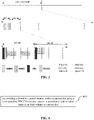
FIG. 2 is a schematic view showing the application of the methods according to some embodiments of the present disclosure; -
FIG. 3 is another schematic view showing the application of the methods according to some embodiments of the present disclosure; -
FIG. 4 is a flow chart of a method for transmitting a downlink control channel according to one embodiment of the present disclosure; -
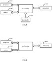
FIG. 5 is a schematic view showing a UE according to one embodiment of the present disclosure; and -
FIG. 6 is a schematic view showing a network device according to one embodiment of the present disclosure. - In order to make the objects, the technical solutions and the advantages of the present disclosure more apparent, the present disclosure will be described hereinafter in a clear and complete manner in conjunction with the drawings and embodiments.
- As shown in
FIG. 1 , the present disclosure provides in some embodiments a method for detecting a downlink control channel for a UE, which includesStep 101 of detecting the downlink control channel within a current slot using a corresponding PDCCH resource pattern in accordance with whether there is an SSB within the current slot. According to the embodiments of the present disclosure, the downlink control channel is detected within the current slot using an appropriate PDCCH resource pattern in accordance with whether there is the SSB within the current slot. As a result, it is able to prevent a decrease in a downlink control channel capacity, thereby to prevent the occurrence of such a circumstance where it is impossible to transmit the downlink control channel within the slot where the SSB is transmitted. - Of course, the downlink control channel is transmitted by a corresponding network device within the current slot using the PDCCH resource pattern in accordance with whether there is the SSB within the current slot, so that the UE detects and receives the downlink control information.
- In some possible embodiments of the present disclosure,
Step 101 includes detecting the downlink control channel using a first PDCCH resource pattern within a slot where the SSB is transmitted. The first PDCCH resource pattern occupies consecutive N1 symbols in a time domain and B1 RBs in a frequency domain, and the N1 symbols do not overlap symbols for transmitting the SSB, where N1 is a positive integer greater than or equal to 1, and B1 is a positive integer greater than or equal to 1. - Here, the first PDCCH resource pattern is a PDCCH resource pattern suitable for detecting the downlink control channel within the slot where the SSB is transmitted. The first PDCCH resource pattern occupies consecutive N1 symbols in the time domain, and occupies B1 RBs in the frequency domain. In this regard, the UE detects and receives the downlink control channel using the first PDCCH resource pattern within the slot where there is the SSB.
- Correspondingly, the network device transmits the downlink control channel using the first PDCCH resource pattern within the slot where the SSB is transmitted.
- In the embodiments of the present disclosure, in order to ensure that a PDCCH transmission resource does not overlap the SSB in the time domain. In some possible embodiments of the present disclosure, the first PDCCH resource pattern is pre-defined in a protocol or determined in accordance with a resource position of the SSB.
- Here, for the first PDCCH resource pattern predefined in a protocol or determined in accordance with the resource position of the SSB, the consecutive N1 symbols occupied in the time domain do not overlap the SSB in the time domain.
- In addition, in the embodiments of the present disclosure,
Step 101 further includes detecting the downlink control channel using a second PDCCH resource pattern within a slot where no SSB is transmitted. The second PDCCH resource pattern occupies consecutive N2 symbols in a time domain and B2 RBs in a frequency domain, where N2 and B2 are each a positive integer greater than or equal to 1. - Here, the second PDCCH resource pattern is a PDCCH resource pattern suitable for detecting the downlink control channel within the slot where no SSB is transmitted. The second PDCCH resource pattern occupies consecutive N2 symbols in the time domain, and occupies B2 RBs in the frequency domain. In this regard, the UE detects and receives the downlink control channel using the second PDCCH resource pattern within the slot where there is no SSB.
- Correspondingly, the network device transmits the downlink control channel using the second PDCCH resource pattern within the slot where no SSB is transmitted.
- In some possible embodiments of the present disclosure, the second PDCCH resource pattern is configured by the network device through high layer signaling.
- The application of the method in the embodiments of the present disclosure will be described hereinafter in conjunction with specific scenarios.
- In a first scenario, the network device, e.g., a base station, needs to transmit two SSBs (
SSB# 1 and SSB#2) within a period of 20ms, and the SSBs are transmitted within 5ms. Within a slot (slot#0) where the SSBs are transmitted,SSB# 1 occupies symbols {#2 #3 #4 #5}, andSSB# 2 occupies symbols {#8 #9 #10 #11}. A downlink control channel transmission region configured by the base station for the UE is symbols {#1 #2 #3} within the slot, and it occupies an entire transmission bandwidth B3 in the frequency domain. Thesymbol # 0 is used for transmitting a CRS. The downlink control channel transmission region is called as aPDCCH resource pattern 1. Meanwhile, aPDCCH resource pattern 2 is defined as occupying the symbol {#1} within the slot in the time domain and occupying the entire transmission bandwidth B3 in the frequency domain. As shown inFIG. 2 , within the slot (slot#1) where no SSB is transmitted, the base station transmits the downlink control channel using thePDCCH resource pattern 1, and the UE detects and receives the downlink control channel using thePDCCH resource pattern 1. Within the slot (slot#0) where the SSB is transmitted, the base station transmits the downlink control channel using thePDCCH resource pattern 2, and the UE detects and receives the downlink control channel using thePDCCH pattern 2. In other words, the base station and the UE adaptively and flexibly adjust a transmission region and a reception region for the downlink control channel in accordance with a transmission position of the SSB. - In this regard, the base station does not need to transmit the downlink control channel using a single PDCCH resource pattern, so it is able to prevent a decrease in a control channel capacity within the slot where the SSB is transmitted, and enable the UE to detect and receive the PDCCH within the slot where the SSB is transmitted.
- In a second scenario, the network device, e.g., a base station, needs to transmit two SSBs (
SSB# 1 and SSB#2) within a period of 20ms, and the SSBs are transmitted within 5ms. Within a slot (slot#0) where the SSBs are transmitted,SSB# 1 occupies symbols {#2 #3 #4 #5}, andSSB# 2 occupies symbols {#8 #9 #10 #11}. A downlink control channel transmission region configured by the base station for the UE is symbols {#1 #2 #3} within the slot, and it occupies a bandwidth B4 in the frequency domain. The bandwidth B4 is determined implicitly in accordance with a size of a frequency domain ofCORESET# 0, e.g., it occupies a same number of RBs in the frequency domain asCORESET# 0. Thesymbol # 0 is used for transmitting a Cell Reference Signal (CRS). The downlink control channel transmission region is called as aPDCCH resource pattern 3. Meanwhile, aPDCCH resource pattern 4 is defined as occupying the symbol {#1} within the slot in the time domain and occupying an entire transmission bandwidth B5 in the frequency domain, where B5>B4. - As shown in
FIG. 3 , within the slot (slot#1) where no SSB is transmitted, the base station transmits the downlink control channel using thePDCCH resource pattern 4, and the UE detects and receives the downlink control channel using thePDCCH resource pattern 4. Within the slot (slot#0) where the SSB is transmitted, the base station transmits the downlink control channel using thePDCCH resource pattern 3, and the UE detects and receives the downlink control channel using thePDCCH pattern 3. In other words, the base station and the UE adaptively and flexibly adjust a transmission region and a reception region for the downlink control channel in accordance with a transmission position of the SSB. - In this regard, the base station does not need to transmit the downlink control channel using a single PDCCH resource pattern, so it is able to prevent a decrease in a control channel capacity within the slot where the SSB is transmitted, and enable the UE to detect and receive the PDCCH within the slot where the SSB is transmitted. According to the method for detecting the downlink control channel in the embodiments of the present disclosure, the downlink control channel is detected within the current slot using an appropriate PDCCH resource pattern in accordance with whether there is the SSB within the current slot. As a result, it is able to prevent a decrease in the downlink control channel capacity, thereby to prevent the occurrence of such a circumstance where it is impossible to transmit the downlink control channel within the slot where the SSB is transmitted.
- As shown in
FIG. 4 , the present disclosure provides in some embodiments a method for transmitting a downlink control channel for a network device, which includesStep 401 of transmitting the downlink control channel within a current slot using a corresponding PDCCH resource pattern in accordance with whether there is an SSB within the current slot. - Through this step, the network device transmits the downlink control channel within the current slot using an appropriate PDCCH resource pattern in accordance with whether there is the SSB within the current slot. As a result, it is able to prevent a decrease in a downlink control channel capacity, thereby to prevent the occurrence of such a circumstance where it is impossible to transmit the downlink control channel within the slot where the SSB is transmitted.
- In some possible embodiments of the present disclosure,
Step 401 includes transmitting the downlink control channel using a first PDCCH resource pattern within a slot where the SSB is transmitted. The first PDCCH resource pattern occupies consecutive N1 symbols in a time domain and B1 RBs in a frequency domain, and the N1 symbols do not overlap symbols for transmitting the SSB, where N1 is a positive integer greater than or equal to 1, and B1 is a positive integer greater than or equal to 1. - Here, the first PDCCH resource pattern is a PDCCH resource pattern suitable for detecting the downlink control channel within the slot where the SSB is transmitted. The first PDCCH resource pattern occupies consecutive N1 symbols in the time domain, and occupies B1 RBs in the frequency domain.
- In some possible embodiments of the present disclosure, the first PDCCH resource pattern is pre-defined in a protocol or determined in accordance with a resource position of the SSB.
- Here, for the first PDCCH resource pattern predefined in a protocol or determined in accordance with the resource position of the SSB, the consecutive N1 symbols occupied in the time domain do not overlap the SSB in the time domain.
- In some possible embodiments of the present disclosure,
Step 401 includes transmitting the downlink control channel using a second PDCCH resource pattern within a slot where no SSB is transmitted. The second PDCCH resource pattern occupies consecutive N2 symbols in a time domain and B2 RBs in a frequency domain, where N2 and B2 are each a positive integer greater than or equal to 1. - Here, the second PDCCH resource pattern is a PDCCH resource pattern suitable for detecting the downlink control channel within the slot where no SSB is transmitted. The second PDCCH resource pattern occupies consecutive N2 symbols in the time domain, and occupies B2 RBs in the frequency domain. In this regard, the network device transmits the downlink control channel using the second PDCCH resource pattern within the slot where there is no SSB.
- In some possible embodiments of the present disclosure, the second PDCCH resource pattern is configured by a network device through high layer signaling.
- It should be appreciated that, the method is applied to the network device, and cooperates with the above-mentioned method for detecting the downlink control channel for UE to transmit and receive the downlink control channel. The implementation of the method may refer to that of the method for the UE mentioned hereinabove, with a same technical effect.
- As shown in
FIG. 5 , the present disclosure provides in some embodiments a UE, which includes atransceiver 520, amemory 540, aprocessor 510, and a program stored in thememory 540 and executed by theprocessor 510. Theprocessor 510 is configured to execute the program, so as to detect the downlink control channel within a current slot using a corresponding PDCCH resource pattern in accordance with whether there is an SSB within the current slot. - In some possible embodiments of the present disclosure, the
processor 510 is further configured to detect the downlink control channel using a first PDCCH resource pattern within a slot where the SSB is transmitted. The first PDCCH resource pattern occupies consecutive N1 symbols in a time domain and B1 RBs in a frequency domain, and the N1 symbols do not overlap symbols for transmitting the SSB, where N1 is a positive integer greater than or equal to 1, andB 1 is a positive integer greater than or equal to 1. In some possible embodiments of the present disclosure, the first PDCCH resource pattern is pre-defined in a protocol or determined in accordance with a resource position of the SSB. - In some possible embodiments of the present disclosure, the
processor 510 is further configured to detect the downlink control channel using a second PDCCH resource pattern within a slot where no SSB is transmitted. The second PDCCH resource pattern occupies consecutive N2 symbols in a time domain and B2 RBs in a frequency domain, where N2 and B2 are each a positive integer greater than or equal to 1. - In some possible embodiments of the present disclosure, the second PDCCH resource pattern is configured by a network device through high layer signaling.
- In
FIG. 5 , bus architecture may include a number of buses and bridges connected to each other, so as to connect various circuits for one ormore processors 510 and one ormore memories 540. In addition, as is known in the art, the bus architecture may be used to connect any other circuits, such as a circuit for a peripheral device, a circuit for a voltage stabilizer and a power management circuit. A bus interface may be provided, and thetransceiver 520 may consist of a plurality of elements, i.e., a transmitter and a receiver for communication with any other devices over a transmission medium. For example, thetransceiver 520 receives external data from the other device, and transmits data processed by theprocessor 510 to the other device. Depending on properties of a computing system, a user interface 530, e.g., a keypad, a display, a speaker, a microphone or a joystick, may also be provided. - The
processor 510 may take charge of managing a bus 500 as well as general processings. Thememory 540 may store therein data for the operation of theprocessor 510. - In some possible embodiments of the present disclosure, the
processor 510 may be a Central Processing Unit (CPU), an Application Specific Integrated Circuit (ASIC), a Field-Programmable Gate Array (FPGA) or a Complex Programmable Logic Device (CPLD). - As shown in
FIG. 6 , the present disclosure provides in some embodiments a network device, which includes atransceiver 620, amemory 630, aprocessor 610, and a program stored in thememory 630 and executed by theprocessor 610. Theprocessor 610 is configured to execute the program so as to transmit the downlink control channel within a current slot using a corresponding PDCCH resource pattern in accordance with whether there is an SSB within the current slot. - In some possible embodiments of the present disclosure, the
transceiver 620 is configured to transmit the downlink control channel using a first PDCCH resource pattern within a slot where the SSB is transmitted. The first PDCCH resource pattern occupies consecutive N1 symbols in a time domain and B1 RBs in a frequency domain, and the N1 symbols do not overlap symbols for transmitting the SSB, where N1 is a positive integer greater than or equal to 1, and B1 is a positive integer greater than or equal to 1. - In some possible embodiments of the present disclosure, the first PDCCH resource pattern is pre-defined in a protocol or determined in accordance with a resource position of the SSB.
- In some possible embodiments of the present disclosure, the
transceiver 620 is further configured to transmit the downlink control channel using a second PDCCH resource pattern within a slot where no SSB is transmitted. The second PDCCH resource pattern occupies consecutive N2 symbols in a time domain and B2 RBs in a frequency domain, where N2 and B2 are each a positive integer greater than or equal to 1. - In some possible embodiments of the present disclosure, the second PDCCH resource pattern is configured by a network device through high layer signaling.
- The
transceiver 620 is configured to receive and transmit data under the control of theprocessor 610. InFIG. 6 , bus architecture may include a number of buses and bridges connected to each other, so as to connect various circuits for one ormore processors 610 and one ormore memories 630. In addition, as is known in the art, the bus architecture may be used to connect any other circuits, such as a circuit for a peripheral device, a circuit for a voltage stabilizer and a power management circuit. A bus interface may be provided, and thetransceiver 620 may consist of a plurality of elements, i.e., a transmitter and a receiver for communication with any other devices over a transmission medium. Theprocessor 610 may take charge of managing the bus architecture as well as general processings. Thememory 630 may store therein data for the operation of theprocessor 610. - The present disclosure further provides in some embodiments a device for detecting a downlink control channel for a UE, which includes a processing module configured to detect the downlink control channel within a current slot using a corresponding PDCCH resource pattern in accordance with whether there is an SSB within the current slot.
- In some possible embodiments of the present disclosure, the processing module includes a first processing sub-module configured to detect the downlink control channel using a first PDCCH resource pattern within a slot where the SSB is transmitted.
- The first PDCCH resource pattern occupies consecutive N1 symbols in a time domain and B1 RBs in a frequency domain, and the N1 symbols do not overlap symbols for transmitting the SSB, where N1 is a positive integer greater than or equal to 1, and B1 is a positive integer greater than or equal to 1.
- In some possible embodiments of the present disclosure, the first PDCCH resource pattern is pre-defined in a protocol or determined in accordance with a resource position of the SSB.
- In some possible embodiments of the present disclosure, the processing module includes a second processing sub-module configured to detect the downlink control channel using a second PDCCH resource pattern within a slot where no SSB is transmitted. The second PDCCH resource pattern occupies consecutive N2 symbols in a time domain and B2 RBs in a frequency domain, where N2 and B2 are each a positive integer greater than or equal to 1.
- In some possible embodiments of the present disclosure, the second PDCCH resource pattern is configured by a network device through high layer signaling.
- According to the device in the embodiments of the present disclosure, the downlink control channel is detected within the current slot using an appropriate PDCCH resource pattern in accordance with whether there is the SSB within the current slot. As a result, it is able to prevent a decrease in a downlink control channel capacity, thereby to prevent the occurrence of such a circumstance where it is impossible to transmit the downlink control channel within the slot where the SSB is transmitted.
- It should be appreciated that, the device is configured to implement the above-mentioned method for the UE, and the implementation of the device may refer to that of the method for the UE with a same technical effect.
- The present disclosure further provides in some embodiments a device for transmitting a downlink control channel for a network device, which includes a transmission module configured to transmit the downlink control channel within a current slot using a corresponding PDCCH resource pattern in accordance with whether there is an SSB within the current slot.
- In some possible embodiments of the present disclosure, the transmission module includes a first transmission sub-module configured to transmit the downlink control channel using a first PDCCH resource pattern within a slot where the SSB is transmitted. The first PDCCH resource pattern occupies consecutive N1 symbols in a time domain and B1 RBs in a frequency domain, and the N1 symbols do not overlap symbols for transmitting the SSB, where N1 is a positive integer greater than or equal to 1, and B1 is a positive integer greater than or equal to 1.
- In some possible embodiments of the present disclosure, the first PDCCH resource pattern is pre-defined in a protocol or determined in accordance with a resource position of the SSB.
- In some possible embodiments of the present disclosure, the transmission module includes a second transmission sub-module configured to transmit the downlink control channel using a second PDCCH resource pattern within a slot where no SSB is transmitted. The second PDCCH resource pattern occupies consecutive N2 symbols in a time domain and B2 RBs in a frequency domain, where N2 and B2 are each a positive integer greater than or equal to 1.
- In some possible embodiments of the present disclosure, the second PDCCH resource pattern is configured by a network device through high layer signaling.
- According to the device in the embodiments of the present disclosure, the downlink control channel is transmitted within the current slot using an appropriate PDCCH resource pattern in accordance with whether there is the SSB within the current slot. As a result, it is able to prevent a decrease in a downlink control channel capacity, thereby to prevent the occurrence of such a circumstance where it is impossible to transmit the downlink control channel within the slot where the SSB is transmitted.
- It should be appreciated that, the device is configured to implement the above-mentioned method for the network device, and the implementation of the device may refer to that of the method for the network device with a same technical effect.
- The present disclosure further provides in some embodiments a computer-readable storage medium storing therein a program. The program is executed by a processor so as to implement the steps in the above-mentioned method for detecting the downlink control channel for the UE, or the steps in the above-mentioned method for transmitting the downlink control channel.
- The computer-readable storage medium may include volatile or nonvolitle, mobile or immobile storage medium capable of storing therein information using any method or technique. The information may be a computer-readable instruction, a data structure, a program or any other data. The computer-readable storage medium may include, but not limited to, a Random Access Memory (e.g., Phase Change Random Access Memory (PRAM), Static Random Access Memory (SRAM) or Dynamic Random Access Memory (DRAM)), a Read Only Memory (ROM) (e.g., an Electrically Erasable Programmable Read Only Memory (EEPROM), a flash memory, a Compact Disc Read Only Memory (CD-ROM) or a Digital Video Disk (DVD)), a magnetic storage device (e.g., a cassette magnetic tape or a magnetic disk), or any other non-transmission medium capable of storing therein information which can be accessed by a computing device. As defined in the present disclosure, the computer-readable storage medium may not include any transitory media, e.g., modulated data signal or carrier.
- It should be further appreciated that, the UE described in the specification includes, but not limited to, smart phone or tablet computer. The functional members described in the specification are referred to as modules, so as to emphasize the independence of the implementation in a more particular manner.
- In the embodiments of the present disclosure, the modules are implemented by software, so as to be executed by various processors. For example, an identified, executable code module includes one or more physical or logical blocks including computer instructions, and the module is constructed as an image, a process or a function. Even so, the executable codes of the identified modules are unnecessary to be physically located together, but include different instructions stored in different locations. When these instructions are logically combined together, they form the modules and achieve the prescribed purposes of the modules.
- Actually, the executable code module is a single instruction or a plurality of instructions, and even it is distributed at different code segments, in different programs, or across a plurality of memory devices. Also, operational data is identified in the modules, implemented in any appropriate form, and organized in any data structure of an appropriate type. The operational data is collected as a single data set, or distributed at different locations (including different memory devices), and it is at least partially present in a system or network merely as an electronic signal.
- When the modules can be implemented by software, considering the current hardware level, a person skilled in the art can build a corresponding hardware circuit to achieve the corresponding function if taking no account of the cost. The hardware circuit includes a conventional very-large-scale integration (VLSI) circuit, a gate array, an existing semiconductor such as a logic chip and a transistor, or other discrete components. The modules are further implemented by a programmable hardware device, such as a field-programmable gate array, a programmable array logic device and a programmable logic device.
- It should be appreciated that, the embodiments of the present disclosure are implemented by hardware, software, firmware, middleware, microcode or a combination thereof. For the hardware implementation, the processor includes one or more of an Application Specific Integrated Circuits (ASIC), a Digital Signal Processor (DSP), a DSP device (DSPD), a Programmable Logic Device (PLD), a Field-Programmable Gate Array (FPGA), a general-purpose processor, a controller, a microcontroller, a microprocessor, any other electronic unit capable of achieving the functions in the present disclosure, or a combination thereof.
- The above illustrative embodiments have been described with respect to the drawings, and the other embodiments are also feasible without departing from the spirit and teaching of the present disclosure, so the illustrative embodiments shall not be used to limit the scope of the present disclosure. More definitely, the illustrative embodiments are provided so as to make the present disclosure complete, and deliver the scope of the present disclosure to those skilled in the art. In the drawings, sizes and relative sizes of the members are scaled up for clarification. Terms involved in the present disclosure are merely used to describing the specific embodiments, but shall not be inclined to become a restricted use. Unless otherwise defined, such words as "one" or "one of" are merely used to represent the existence of at least one member, rather than to limit the number thereof. Such words as "include" or "including" intend to indicate that there are the features, integers, steps, operations, elements and/or assemblies, without excluding the existence or addition of one or more other features, integers, steps, operations, elements, assemblies and/or combinations thereof. Unless otherwise defined, a numerical range includes an upper limit, a lower limit and any sub-range. The above embodiments are for illustrative purposes only, but the present disclosure is not limited thereto. Obviously, a person skilled in the art may make further modifications and improvements without departing from the spirit of the present disclosure, and these modifications and improvements shall also fall within the scope of the present disclosure.
Claims (23)
- A method for detecting a downlink control channel performed by a User Equipment (UE), comprising:
detecting the downlink control channel within a current slot using a corresponding Physical Downlink Control Channel (PDCCH) resource pattern in accordance with whether there is a Synchronization Signal Block (SSB) within the current slot. - The method according to claim 1, wherein the detecting the downlink control channel within the current slot using the corresponding PDCCH resource pattern in accordance with whether there is the SSB within the current slot comprises:detecting the downlink control channel using a first PDCCH resource pattern within a slot where the SSB is transmitted,wherein the first PDCCH resource pattern occupies consecutive N1 symbols in a time domain and B1 Resource Blocks (RBs) in a frequency domain, and the N1 symbols do not overlap symbols for transmitting the SSB, where N1 is a positive integer greater than or equal to 1, and B1 is a positive integer greater than or equal to 1.
- The method according to claim 2, wherein the first PDCCH resource pattern is pre-defined in a protocol or determined in accordance with a resource position of the SSB.
- The method according to claim 1, wherein the detecting the downlink control channel within the current slot using the corresponding PDCCH resource pattern in accordance with whether there is the SSB within the current slot comprises:detecting the downlink control channel using a second PDCCH resource pattern within a slot where no SSB is transmitted,wherein the second PDCCH resource pattern occupies consecutive N2 symbols in a time domain and B2 RBs in a frequency domain, where N2 and B2 are each a positive integer greater than or equal to 1.
- The method according to claim 4, wherein the second PDCCH resource pattern is configured by a network device through high layer signaling.
- A method for transmitting a downlink control channel performed by a network device, comprising:
transmitting the downlink control channel within a current slot using a corresponding Physical Downlink Control Channel (PDCCH) resource pattern in accordance with whether there is a Synchronization Signal Block (SSB) within the current slot. - The method according to claim 6, wherein the transmitting the downlink control channel within the current slot using the corresponding PDCCH resource pattern in accordance with whether there is the SSB within the current slot comprises:transmitting the downlink control channel using a first PDCCH resource pattern within a slot where the SSB is transmitted,wherein the first PDCCH resource pattern occupies consecutive N1 symbols in a time domain and B1 Resource Blocks (RBs) in a frequency domain, and the N1 symbols do not overlap symbols for transmitting the SSB, where N1 is a positive integer greater than or equal to 1, and B1 is a positive integer greater than or equal to 1.
- The method according to claim 7, wherein the first PDCCH resource pattern is pre-defined in a protocol or determined in accordance with a resource position of the SSB.
- The method according to claim 6, wherein the transmitting the downlink control channel within the current slot using the corresponding PDCCH resource pattern in accordance with whether there is the SSB within the current slot comprises:transmitting the downlink control channel using a second PDCCH resource pattern within a slot where no SSB is transmitted,wherein the second PDCCH resource pattern occupies consecutive N2 symbols in a time domain and B2 RBs in a frequency domain, where N2 and B2 are each a positive integer greater than or equal to 1.
- The method according to claim 9, wherein the second PDCCH resource pattern is configured by a network device through high layer signaling.
- A User Equipment (UE), comprising a transceiver, a memory, a processor, and a program stored in the memory and executed by the processor, wherein the processor is configured to execute the program, so as to detect the downlink control channel within a current slot using a corresponding Physical Downlink Control Channel (PDCCH) resource pattern in accordance with whether there is a Synchronization Signal Block (SSB) within the current slot.
- The UE according to claim 11, wherein the processor is further configured to detect the downlink control channel using a first PDCCH resource pattern within a slot where the SSB is transmitted,
wherein the first PDCCH resource pattern occupies consecutive N1 symbols in a time domain and B1 Resource Blocks (RBs) in a frequency domain, and the N1 symbols do not overlap symbols for transmitting the SSB, where N1 is a positive integer greater than or equal to 1, and B1 is a positive integer greater than or equal to 1. - The UE according to claim 12, wherein the first PDCCH resource pattern is pre-defined in a protocol or determined in accordance with a resource position of the SSB.
- The UE according to claim 11, wherein the processor is further configured to detect the downlink control channel using a second PDCCH resource pattern within a slot where no SSB is transmitted,
wherein the second PDCCH resource pattern occupies consecutive N2 symbols in a time domain and B2 RBs in a frequency domain, where N2 and B2 are each a positive integer greater than or equal to 1. - The UE according to claim 14, wherein the second PDCCH resource pattern is configured by a network device through high layer signaling.
- A network device, comprising a transceiver, a memory, a processor, and a program stored in the memory and executed by the processor, wherein the transceiver is configured to execute the program, so as to transmit the downlink control channel within a current slot using a corresponding Physical Downlink Control Channel (PDCCH) resource pattern in accordance with whether there is a Synchronization Signal Block (SSB) within the current slot.
- The network device according to claim 16, wherein the transceiver is further configured to transmit the downlink control channel using a first PDCCH resource pattern within a slot where the SSB is transmitted,
wherein the first PDCCH resource pattern occupies consecutive N1 symbols in a time domain and B1 Resource Blocks (RBs) in a frequency domain, and the N1 symbols do not overlap symbols for transmitting the SSB, where N1 is a positive integer greater than or equal to 1, and B1 is a positive integer greater than or equal to 1. - The network device according to claim 17, wherein the first PDCCH resource pattern is pre-defined in a protocol or determined in accordance with a resource position of the SSB.
- The network device according to claim 16, wherein the transceiver is further configured to transmit the downlink control channel using a second PDCCH resource pattern within a slot where no SSB is transmitted,
wherein the second PDCCH resource pattern occupies consecutive N2 symbols in a time domain and B2 RBs in a frequency domain, where N2 and B2 are each a positive integer greater than or equal to 1. - The network device according to claim 19, wherein the second PDCCH resource pattern is configured by a network device through high layer signaling.
- A device for detecting a downlink control channel for a User Equipment (UE), comprising a processing module configured to detect the downlink control channel within a current slot using a corresponding Physical Downlink Control Channel (PDCCH) resource pattern in accordance with whether there is a Synchronization Signal Block (SSB) within the current slot.
- A device for transmitting a downlink control channel for a network device, comprising a transmission module configured to transmit the downlink control channel within a current slot using a corresponding Physical Downlink Control Channel (PDCCH) resource pattern in accordance with whether there is a Synchronization Signal Block (SSB) within the current slot.
- A computer-readable storage medium storing therein a program, wherein the program is executed by a processor so as to implement the steps in the method according to any one of claims 1 to 5, or the steps in the method
according to any one of claims 6 to 10.
Applications Claiming Priority (2)
| Application Number | Priority Date | Filing Date | Title |
|---|---|---|---|
| CN201910651951.8A CN112242889B (en) | 2019-07-18 | 2019-07-18 | Detection method, transmission method and equipment of downlink control channel |
| PCT/CN2020/101846 WO2021008517A1 (en) | 2019-07-18 | 2020-07-14 | Method for detecting downlink control channel, and transmission method and device |
Publications (3)
| Publication Number | Publication Date |
|---|---|
| EP4002740A1 true EP4002740A1 (en) | 2022-05-25 |
| EP4002740A4 EP4002740A4 (en) | 2022-08-24 |
| EP4002740B1 EP4002740B1 (en) | 2025-03-12 |
Family
ID=74168048
Family Applications (1)
| Application Number | Title | Priority Date | Filing Date |
|---|---|---|---|
| EP20841325.2A Active EP4002740B1 (en) | 2019-07-18 | 2020-07-14 | Method for detecting downlink control channel, and transmission method and device |
Country Status (4)
| Country | Link |
|---|---|
| US (1) | US12113748B2 (en) |
| EP (1) | EP4002740B1 (en) |
| CN (1) | CN112242889B (en) |
| WO (1) | WO2021008517A1 (en) |
Family Cites Families (27)
| Publication number | Priority date | Publication date | Assignee | Title |
|---|---|---|---|---|
| US10523354B2 (en) * | 2017-02-24 | 2019-12-31 | Samsung Electronics Co., Ltd. | Method and apparatus for design of NR-SS burst set |
| CN110637488A (en) * | 2017-03-23 | 2019-12-31 | 瑞典爱立信有限公司 | Network node, wireless communication device, method, and computer program |
| EP4145919B1 (en) * | 2017-05-03 | 2025-09-03 | Sony Group Corporation | Efficient utilization of ssbs in new radio systems |
| WO2018226054A1 (en) | 2017-06-08 | 2018-12-13 | 엘지전자 주식회사 | Resource allocation-related signaling method in wireless communication system and device using same |
| AU2018283571B2 (en) * | 2017-06-15 | 2020-07-09 | Lg Electronics Inc. | Method for transmitting and receiving synchronization signal block and device therefor |
| WO2019018778A1 (en) * | 2017-07-21 | 2019-01-24 | Qualcomm Incorporated | Multiplexing demodulation reference signals and synchronization signals in new radio |
| KR102488966B1 (en) * | 2017-09-08 | 2023-01-16 | 삼성전자 주식회사 | Method and apparatus for transmitting and receving control channel and data channel in wirelss communication system |
| JP6970821B2 (en) * | 2017-10-02 | 2021-11-24 | ノキア テクノロジーズ オサケユイチア | Beam-specific and non-beam-specific sync signal block locations for wireless networks |
| US10893543B2 (en) * | 2017-10-30 | 2021-01-12 | Samsung Electronics Co., Ltd. | Method and apparatus for random access design of NR unlicensed |
| US10506588B2 (en) * | 2017-11-17 | 2019-12-10 | Lg Electronics Inc. | Method and apparatus for transmitting and receiving system information |
| US11070333B2 (en) * | 2017-12-21 | 2021-07-20 | Samsung Electronics Co., Ltd. | Method and apparatus for SS/PBCH block frequency location indication |
| CN110011714B (en) * | 2018-01-05 | 2021-06-15 | 维沃移动通信有限公司 | Signal receiving method, transmitting method, user equipment and network equipment |
| US10893431B2 (en) * | 2018-01-19 | 2021-01-12 | Asustek Computer Inc. | Method and apparatus for beam failure reporting under multicell configuration in a wireless communication system |
| WO2019157657A1 (en) * | 2018-02-13 | 2019-08-22 | 北京小米移动软件有限公司 | Information configuration method and apparatus, and base station and user equipment |
| CN110300442B (en) * | 2018-03-23 | 2020-07-28 | 维沃移动通信有限公司 | Signal sending method and network equipment |
| CN108513361B (en) * | 2018-04-04 | 2022-10-21 | 宇龙计算机通信科技(深圳)有限公司 | Channel access method, device and storage medium |
| CN110446259B (en) * | 2018-05-04 | 2022-04-15 | 大唐移动通信设备有限公司 | Position determination method of paging opportunity and communication equipment |
| CN110475360B (en) * | 2018-05-10 | 2023-05-02 | 华硕电脑股份有限公司 | Method and apparatus for beam indication for uplink transmission in a wireless communication system |
| WO2020175388A1 (en) * | 2019-02-28 | 2020-09-03 | 株式会社Nttドコモ | Terminal and wireless communication method |
| WO2021038264A1 (en) * | 2019-08-26 | 2021-03-04 | Orope France Sarl | Method for connecting a user equipment to a mobile telecommunication system, user equipment and base station |
| CN114503646B (en) * | 2019-10-02 | 2023-10-27 | Lg电子株式会社 | Method and apparatus for transmitting and receiving wireless signals in a wireless communication system |
| KR102737009B1 (en) * | 2019-10-02 | 2024-12-03 | 엘지전자 주식회사 | Method and apparatus for transmitting/receiving wireless signal in wireless communication system |
| US11924700B2 (en) * | 2020-01-10 | 2024-03-05 | Qualcomm Incorporated | L1/L2 based cell selection |
| US11792753B2 (en) * | 2020-03-16 | 2023-10-17 | Qualcomm Incorporated | Synchronization signal block time domain pattern design |
| US12309830B2 (en) * | 2020-03-23 | 2025-05-20 | Qualcomm Incorporated | Access procedure configuration of a millimeter wave repeater |
| CN115553043A (en) * | 2020-05-14 | 2022-12-30 | 艾普拉控股有限公司 | Initial access to new radio equipment for reduced capabilities |
| CN114071429B (en) * | 2020-08-07 | 2025-07-11 | 华为技术有限公司 | A physical downlink control channel enhancement method, communication device and system |
-
2019
- 2019-07-18 CN CN201910651951.8A patent/CN112242889B/en active Active
-
2020
- 2020-07-14 EP EP20841325.2A patent/EP4002740B1/en active Active
- 2020-07-14 US US17/619,058 patent/US12113748B2/en active Active
- 2020-07-14 WO PCT/CN2020/101846 patent/WO2021008517A1/en not_active Ceased
Also Published As
| Publication number | Publication date |
|---|---|
| US12113748B2 (en) | 2024-10-08 |
| CN112242889B (en) | 2022-07-01 |
| US20220360418A1 (en) | 2022-11-10 |
| EP4002740A4 (en) | 2022-08-24 |
| CN112242889A (en) | 2021-01-19 |
| WO2021008517A1 (en) | 2021-01-21 |
| EP4002740B1 (en) | 2025-03-12 |
Similar Documents
| Publication | Publication Date | Title |
|---|---|---|
| US20240334498A1 (en) | Information transmission method, apparatus, and device | |
| EP3691376B1 (en) | Method and device for determining time frequency resources | |
| US20250220647A1 (en) | Resource configuration method and apparatus, and terminal and network side device | |
| EP3678433A1 (en) | Method for determining resource allocation and indicating resource allocation, terminal and network-side equipment | |
| US12101762B2 (en) | Information transmission method, apparatus and device | |
| US12167351B2 (en) | Method for sending and receiving signal, terminal and apparatus | |
| CN105898872A (en) | Uplink transmission method and device | |
| US20240298357A1 (en) | Uplink resource allocation method and device, base station, and terminal | |
| US11589266B2 (en) | Resource configuration method and device, and computer storage medium | |
| US20250105995A1 (en) | Transmission processing method, device and apparatus | |
| CN107294673B (en) | Uplink transmission method and device | |
| EP4195566A1 (en) | Information indication method, node, and storage medium | |
| US12301500B2 (en) | Information transmission method, device and apparatus | |
| WO2021057341A1 (en) | Information sending method, information receiving method and device | |
| EP4009724B1 (en) | Terminal capability processing method, apparatus, and device | |
| US12113748B2 (en) | Method for detecting downlink control channel, method for transmitting downlink control channel, and relevant devices | |
| US12052666B2 (en) | Signal processing method and apparatus, and device with time-domain position for monitoring power-saving signal | |
| CN115913508A (en) | A data mapping method, communication node and storage medium | |
| US20230155805A1 (en) | Method and apparatus for transmitting and receiving time division duplex configuration indication information and terminal | |
| WO2021031925A1 (en) | Signal sending method and apparatus, and storage medium | |
| CN112242890B (en) | Detection method, transmission method and equipment of downlink control channel | |
| EP4518390A1 (en) | Resource scheduling method, resource use method, network device, terminal device and medium | |
| US20250119809A1 (en) | Cell switching method, electronic device, and computer-readable storage medium | |
| RU2846453C2 (en) | Method and apparatus for determining a transmission configuration indication state | |
| CN121970283A (en) | Configuration of control resource sets in sub-band non-overlapping full duplex |
Legal Events
| Date | Code | Title | Description |
|---|---|---|---|
| STAA | Information on the status of an ep patent application or granted ep patent |
Free format text: STATUS: THE INTERNATIONAL PUBLICATION HAS BEEN MADE |
|
| PUAI | Public reference made under article 153(3) epc to a published international application that has entered the european phase |
Free format text: ORIGINAL CODE: 0009012 |
|
| STAA | Information on the status of an ep patent application or granted ep patent |
Free format text: STATUS: REQUEST FOR EXAMINATION WAS MADE |
|
| 17P | Request for examination filed |
Effective date: 20211214 |
|
| AK | Designated contracting states |
Kind code of ref document: A1 Designated state(s): AL AT BE BG CH CY CZ DE DK EE ES FI FR GB GR HR HU IE IS IT LI LT LU LV MC MK MT NL NO PL PT RO RS SE SI SK SM TR |
|
| A4 | Supplementary search report drawn up and despatched |
Effective date: 20220725 |
|
| RIC1 | Information provided on ipc code assigned before grant |
Ipc: H04W 24/02 20090101ALI20220719BHEP Ipc: H04L 5/00 20060101AFI20220719BHEP |
|
| DAV | Request for validation of the european patent (deleted) | ||
| DAX | Request for extension of the european patent (deleted) | ||
| GRAP | Despatch of communication of intention to grant a patent |
Free format text: ORIGINAL CODE: EPIDOSNIGR1 |
|
| STAA | Information on the status of an ep patent application or granted ep patent |
Free format text: STATUS: GRANT OF PATENT IS INTENDED |
|
| INTG | Intention to grant announced |
Effective date: 20241010 |
|
| GRAS | Grant fee paid |
Free format text: ORIGINAL CODE: EPIDOSNIGR3 |
|
| GRAA | (expected) grant |
Free format text: ORIGINAL CODE: 0009210 |
|
| STAA | Information on the status of an ep patent application or granted ep patent |
Free format text: STATUS: THE PATENT HAS BEEN GRANTED |
|
| AK | Designated contracting states |
Kind code of ref document: B1 Designated state(s): AL AT BE BG CH CY CZ DE DK EE ES FI FR GB GR HR HU IE IS IT LI LT LU LV MC MK MT NL NO PL PT RO RS SE SI SK SM TR |
|
| REG | Reference to a national code |
Ref country code: GB Ref legal event code: FG4D |
|
| REG | Reference to a national code |
Ref country code: CH Ref legal event code: EP |
|
| REG | Reference to a national code |
Ref country code: DE Ref legal event code: R096 Ref document number: 602020047694 Country of ref document: DE |
|
| REG | Reference to a national code |
Ref country code: IE Ref legal event code: FG4D |
|
| PG25 | Lapsed in a contracting state [announced via postgrant information from national office to epo] |
Ref country code: RS Free format text: LAPSE BECAUSE OF FAILURE TO SUBMIT A TRANSLATION OF THE DESCRIPTION OR TO PAY THE FEE WITHIN THE PRESCRIBED TIME-LIMIT Effective date: 20250612 |
|
| PG25 | Lapsed in a contracting state [announced via postgrant information from national office to epo] |
Ref country code: FI Free format text: LAPSE BECAUSE OF FAILURE TO SUBMIT A TRANSLATION OF THE DESCRIPTION OR TO PAY THE FEE WITHIN THE PRESCRIBED TIME-LIMIT Effective date: 20250312 |
|
| PG25 | Lapsed in a contracting state [announced via postgrant information from national office to epo] |
Ref country code: ES Free format text: LAPSE BECAUSE OF FAILURE TO SUBMIT A TRANSLATION OF THE DESCRIPTION OR TO PAY THE FEE WITHIN THE PRESCRIBED TIME-LIMIT Effective date: 20250312 |
|
| REG | Reference to a national code |
Ref country code: LT Ref legal event code: MG9D |
|
| PG25 | Lapsed in a contracting state [announced via postgrant information from national office to epo] |
Ref country code: NO Free format text: LAPSE BECAUSE OF FAILURE TO SUBMIT A TRANSLATION OF THE DESCRIPTION OR TO PAY THE FEE WITHIN THE PRESCRIBED TIME-LIMIT Effective date: 20250612 |
|
| PG25 | Lapsed in a contracting state [announced via postgrant information from national office to epo] |
Ref country code: HR Free format text: LAPSE BECAUSE OF FAILURE TO SUBMIT A TRANSLATION OF THE DESCRIPTION OR TO PAY THE FEE WITHIN THE PRESCRIBED TIME-LIMIT Effective date: 20250312 |
|
| REG | Reference to a national code |
Ref country code: NL Ref legal event code: MP Effective date: 20250312 |
|
| PG25 | Lapsed in a contracting state [announced via postgrant information from national office to epo] |
Ref country code: LV Free format text: LAPSE BECAUSE OF FAILURE TO SUBMIT A TRANSLATION OF THE DESCRIPTION OR TO PAY THE FEE WITHIN THE PRESCRIBED TIME-LIMIT Effective date: 20250312 |
|
| PG25 | Lapsed in a contracting state [announced via postgrant information from national office to epo] |
Ref country code: BG Free format text: LAPSE BECAUSE OF FAILURE TO SUBMIT A TRANSLATION OF THE DESCRIPTION OR TO PAY THE FEE WITHIN THE PRESCRIBED TIME-LIMIT Effective date: 20250312 Ref country code: GR Free format text: LAPSE BECAUSE OF FAILURE TO SUBMIT A TRANSLATION OF THE DESCRIPTION OR TO PAY THE FEE WITHIN THE PRESCRIBED TIME-LIMIT Effective date: 20250613 |
|
| REG | Reference to a national code |
Ref country code: AT Ref legal event code: MK05 Ref document number: 1775935 Country of ref document: AT Kind code of ref document: T Effective date: 20250312 |
|
| PG25 | Lapsed in a contracting state [announced via postgrant information from national office to epo] |
Ref country code: NL Free format text: LAPSE BECAUSE OF FAILURE TO SUBMIT A TRANSLATION OF THE DESCRIPTION OR TO PAY THE FEE WITHIN THE PRESCRIBED TIME-LIMIT Effective date: 20250312 |
|
| PG25 | Lapsed in a contracting state [announced via postgrant information from national office to epo] |
Ref country code: SE Free format text: LAPSE BECAUSE OF FAILURE TO SUBMIT A TRANSLATION OF THE DESCRIPTION OR TO PAY THE FEE WITHIN THE PRESCRIBED TIME-LIMIT Effective date: 20250312 |
|
| PG25 | Lapsed in a contracting state [announced via postgrant information from national office to epo] |
Ref country code: SM Free format text: LAPSE BECAUSE OF FAILURE TO SUBMIT A TRANSLATION OF THE DESCRIPTION OR TO PAY THE FEE WITHIN THE PRESCRIBED TIME-LIMIT Effective date: 20250312 |
|
| PG25 | Lapsed in a contracting state [announced via postgrant information from national office to epo] |
Ref country code: PT Free format text: LAPSE BECAUSE OF FAILURE TO SUBMIT A TRANSLATION OF THE DESCRIPTION OR TO PAY THE FEE WITHIN THE PRESCRIBED TIME-LIMIT Effective date: 20250714 |
|
| PGFP | Annual fee paid to national office [announced via postgrant information from national office to epo] |
Ref country code: DE Payment date: 20250722 Year of fee payment: 6 |
|
| PG25 | Lapsed in a contracting state [announced via postgrant information from national office to epo] |
Ref country code: PL Free format text: LAPSE BECAUSE OF FAILURE TO SUBMIT A TRANSLATION OF THE DESCRIPTION OR TO PAY THE FEE WITHIN THE PRESCRIBED TIME-LIMIT Effective date: 20250312 Ref country code: IT Free format text: LAPSE BECAUSE OF FAILURE TO SUBMIT A TRANSLATION OF THE DESCRIPTION OR TO PAY THE FEE WITHIN THE PRESCRIBED TIME-LIMIT Effective date: 20250312 |
|
| PGFP | Annual fee paid to national office [announced via postgrant information from national office to epo] |
Ref country code: GB Payment date: 20250722 Year of fee payment: 6 |
|
| PG25 | Lapsed in a contracting state [announced via postgrant information from national office to epo] |
Ref country code: AT Free format text: LAPSE BECAUSE OF FAILURE TO SUBMIT A TRANSLATION OF THE DESCRIPTION OR TO PAY THE FEE WITHIN THE PRESCRIBED TIME-LIMIT Effective date: 20250312 |
|
| PGFP | Annual fee paid to national office [announced via postgrant information from national office to epo] |
Ref country code: FR Payment date: 20250725 Year of fee payment: 6 |
|
| PG25 | Lapsed in a contracting state [announced via postgrant information from national office to epo] |
Ref country code: CZ Free format text: LAPSE BECAUSE OF FAILURE TO SUBMIT A TRANSLATION OF THE DESCRIPTION OR TO PAY THE FEE WITHIN THE PRESCRIBED TIME-LIMIT Effective date: 20250312 Ref country code: EE Free format text: LAPSE BECAUSE OF FAILURE TO SUBMIT A TRANSLATION OF THE DESCRIPTION OR TO PAY THE FEE WITHIN THE PRESCRIBED TIME-LIMIT Effective date: 20250312 |
|
| PG25 | Lapsed in a contracting state [announced via postgrant information from national office to epo] |
Ref country code: RO Free format text: LAPSE BECAUSE OF FAILURE TO SUBMIT A TRANSLATION OF THE DESCRIPTION OR TO PAY THE FEE WITHIN THE PRESCRIBED TIME-LIMIT Effective date: 20250312 |
|
| PG25 | Lapsed in a contracting state [announced via postgrant information from national office to epo] |
Ref country code: SK Free format text: LAPSE BECAUSE OF FAILURE TO SUBMIT A TRANSLATION OF THE DESCRIPTION OR TO PAY THE FEE WITHIN THE PRESCRIBED TIME-LIMIT Effective date: 20250312 |
|
| PG25 | Lapsed in a contracting state [announced via postgrant information from national office to epo] |
Ref country code: IS Free format text: LAPSE BECAUSE OF FAILURE TO SUBMIT A TRANSLATION OF THE DESCRIPTION OR TO PAY THE FEE WITHIN THE PRESCRIBED TIME-LIMIT Effective date: 20250712 |
|
| REG | Reference to a national code |
Ref country code: DE Ref legal event code: R097 Ref document number: 602020047694 Country of ref document: DE |
|
| PG25 | Lapsed in a contracting state [announced via postgrant information from national office to epo] |
Ref country code: DK Free format text: LAPSE BECAUSE OF FAILURE TO SUBMIT A TRANSLATION OF THE DESCRIPTION OR TO PAY THE FEE WITHIN THE PRESCRIBED TIME-LIMIT Effective date: 20250312 |
|
| PLBE | No opposition filed within time limit |
Free format text: ORIGINAL CODE: 0009261 |
|
| STAA | Information on the status of an ep patent application or granted ep patent |
Free format text: STATUS: NO OPPOSITION FILED WITHIN TIME LIMIT |
|
| REG | Reference to a national code |
Ref country code: CH Ref legal event code: L10 Free format text: ST27 STATUS EVENT CODE: U-0-0-L10-L00 (AS PROVIDED BY THE NATIONAL OFFICE) Effective date: 20260121 |
|
| 26N | No opposition filed |
Effective date: 20251215 |
|
| REG | Reference to a national code |
Ref country code: CH Ref legal event code: H13 Free format text: ST27 STATUS EVENT CODE: U-0-0-H10-H13 (AS PROVIDED BY THE NATIONAL OFFICE) Effective date: 20260224 |
|
| PG25 | Lapsed in a contracting state [announced via postgrant information from national office to epo] |
Ref country code: LU Free format text: LAPSE BECAUSE OF NON-PAYMENT OF DUE FEES Effective date: 20250714 |
|
| REG | Reference to a national code |
Ref country code: BE Ref legal event code: MM Effective date: 20250731 |
|
| PG25 | Lapsed in a contracting state [announced via postgrant information from national office to epo] |
Ref country code: BE Free format text: LAPSE BECAUSE OF NON-PAYMENT OF DUE FEES Effective date: 20250731 |
|
| PG25 | Lapsed in a contracting state [announced via postgrant information from national office to epo] |
Ref country code: CH Free format text: LAPSE BECAUSE OF NON-PAYMENT OF DUE FEES Effective date: 20250731 |