EP4002653A1 - Motor cooling system for e-boosting device - Google Patents
Motor cooling system for e-boosting device Download PDFInfo
- Publication number
- EP4002653A1 EP4002653A1 EP21202197.6A EP21202197A EP4002653A1 EP 4002653 A1 EP4002653 A1 EP 4002653A1 EP 21202197 A EP21202197 A EP 21202197A EP 4002653 A1 EP4002653 A1 EP 4002653A1
- Authority
- EP
- European Patent Office
- Prior art keywords
- motor
- motor case
- projecting portion
- motor assembly
- hole
- Prior art date
- Legal status (The legal status is an assumption and is not a legal conclusion. Google has not performed a legal analysis and makes no representation as to the accuracy of the status listed.)
- Pending
Links
Images


Classifications
-
- H—ELECTRICITY
- H02—GENERATION; CONVERSION OR DISTRIBUTION OF ELECTRIC POWER
- H02K—DYNAMO-ELECTRIC MACHINES
- H02K5/00—Casings; Enclosures; Supports
- H02K5/04—Casings or enclosures characterised by the shape, form or construction thereof
- H02K5/20—Casings or enclosures characterised by the shape, form or construction thereof with channels or ducts for flow of cooling medium
-
- H—ELECTRICITY
- H02—GENERATION; CONVERSION OR DISTRIBUTION OF ELECTRIC POWER
- H02K—DYNAMO-ELECTRIC MACHINES
- H02K5/00—Casings; Enclosures; Supports
- H02K5/04—Casings or enclosures characterised by the shape, form or construction thereof
- H02K5/06—Cast metal casings
-
- F—MECHANICAL ENGINEERING; LIGHTING; HEATING; WEAPONS; BLASTING
- F04—POSITIVE - DISPLACEMENT MACHINES FOR LIQUIDS; PUMPS FOR LIQUIDS OR ELASTIC FLUIDS
- F04D—NON-POSITIVE-DISPLACEMENT PUMPS
- F04D25/00—Pumping installations or systems
- F04D25/02—Units comprising pumps and their driving means
- F04D25/06—Units comprising pumps and their driving means the pump being electrically driven
-
- F—MECHANICAL ENGINEERING; LIGHTING; HEATING; WEAPONS; BLASTING
- F04—POSITIVE - DISPLACEMENT MACHINES FOR LIQUIDS; PUMPS FOR LIQUIDS OR ELASTIC FLUIDS
- F04D—NON-POSITIVE-DISPLACEMENT PUMPS
- F04D29/00—Details, component parts, or accessories
- F04D29/58—Cooling; Heating; Diminishing heat transfer
- F04D29/5806—Cooling the drive system
-
- H—ELECTRICITY
- H02—GENERATION; CONVERSION OR DISTRIBUTION OF ELECTRIC POWER
- H02K—DYNAMO-ELECTRIC MACHINES
- H02K15/00—Processes or apparatus specially adapted for manufacturing, assembling, maintaining or repairing of dynamo-electric machines
- H02K15/14—Casings; Enclosures; Supports
-
- H—ELECTRICITY
- H02—GENERATION; CONVERSION OR DISTRIBUTION OF ELECTRIC POWER
- H02K—DYNAMO-ELECTRIC MACHINES
- H02K5/00—Casings; Enclosures; Supports
- H02K5/02—Casings or enclosures characterised by the material thereof
-
- H—ELECTRICITY
- H02—GENERATION; CONVERSION OR DISTRIBUTION OF ELECTRIC POWER
- H02K—DYNAMO-ELECTRIC MACHINES
- H02K5/00—Casings; Enclosures; Supports
- H02K5/04—Casings or enclosures characterised by the shape, form or construction thereof
-
- H—ELECTRICITY
- H02—GENERATION; CONVERSION OR DISTRIBUTION OF ELECTRIC POWER
- H02K—DYNAMO-ELECTRIC MACHINES
- H02K5/00—Casings; Enclosures; Supports
- H02K5/04—Casings or enclosures characterised by the shape, form or construction thereof
- H02K5/08—Insulating casings
-
- H—ELECTRICITY
- H02—GENERATION; CONVERSION OR DISTRIBUTION OF ELECTRIC POWER
- H02K—DYNAMO-ELECTRIC MACHINES
- H02K5/00—Casings; Enclosures; Supports
- H02K5/04—Casings or enclosures characterised by the shape, form or construction thereof
- H02K5/20—Casings or enclosures characterised by the shape, form or construction thereof with channels or ducts for flow of cooling medium
- H02K5/203—Casings or enclosures characterised by the shape, form or construction thereof with channels or ducts for flow of cooling medium specially adapted for liquids, e.g. cooling jackets
-
- H—ELECTRICITY
- H02—GENERATION; CONVERSION OR DISTRIBUTION OF ELECTRIC POWER
- H02K—DYNAMO-ELECTRIC MACHINES
- H02K9/00—Arrangements for cooling or ventilating
- H02K9/19—Arrangements for cooling or ventilating for machines with closed casing and closed-circuit cooling using a liquid cooling medium, e.g. oil
-
- F—MECHANICAL ENGINEERING; LIGHTING; HEATING; WEAPONS; BLASTING
- F02—COMBUSTION ENGINES; HOT-GAS OR COMBUSTION-PRODUCT ENGINE PLANTS
- F02B—INTERNAL-COMBUSTION PISTON ENGINES; COMBUSTION ENGINES IN GENERAL
- F02B33/00—Engines characterised by provision of pumps for charging or scavenging
- F02B33/32—Engines with pumps other than of reciprocating-piston type
- F02B33/34—Engines with pumps other than of reciprocating-piston type with rotary pumps
- F02B33/40—Engines with pumps other than of reciprocating-piston type with rotary pumps of non-positive-displacement type
-
- F—MECHANICAL ENGINEERING; LIGHTING; HEATING; WEAPONS; BLASTING
- F02—COMBUSTION ENGINES; HOT-GAS OR COMBUSTION-PRODUCT ENGINE PLANTS
- F02B—INTERNAL-COMBUSTION PISTON ENGINES; COMBUSTION ENGINES IN GENERAL
- F02B39/00—Component parts, details, or accessories relating to, driven charging or scavenging pumps, not provided for in groups F02B33/00 - F02B37/00
- F02B39/02—Drives of pumps; Varying pump drive gear ratio
- F02B39/08—Non-mechanical drives, e.g. fluid drives having variable gear ratio
- F02B39/10—Non-mechanical drives, e.g. fluid drives having variable gear ratio electric
-
- F—MECHANICAL ENGINEERING; LIGHTING; HEATING; WEAPONS; BLASTING
- F02—COMBUSTION ENGINES; HOT-GAS OR COMBUSTION-PRODUCT ENGINE PLANTS
- F02C—GAS-TURBINE PLANTS; AIR INTAKES FOR JET-PROPULSION PLANTS; CONTROLLING FUEL SUPPLY IN AIR-BREATHING JET-PROPULSION PLANTS
- F02C6/00—Plural gas-turbine plants; Combinations of gas-turbine plants with other apparatus; Adaptations of gas-turbine plants for special use
- F02C6/04—Gas-turbine plants providing heated or pressurised working fluid for other apparatus, e.g. without mechanical power output
- F02C6/10—Gas-turbine plants providing heated or pressurised working fluid for other apparatus, e.g. without mechanical power output supplying working fluid to a user, e.g. a chemical process, which returns working fluid to a turbine of the plant
- F02C6/12—Turbochargers, i.e. plants for augmenting mechanical power output of internal-combustion piston engines by increase of charge pressure
Definitions
- the present disclosure generally relates to an e-boosting device and, more particularly, relates to a motor cooling system for an e-boosting device.
- Charging devices such as turbochargers or superchargers, are provided that boost performance by compressing a fluid that is then fed to a fuel cell stack, an engine, etc.
- an e-boosting device is provided that has an electric motor configured to drive and rotate a compressor wheel for compressing an airflow, which is then fed to the fuel cell stack, the engine, etc.
- These charging devices may include a cooling system.
- a cooling system may be provided that directs flow of a coolant through the device to maintain operating temperatures within a predetermined range.
- the electric motor may be cooled, for example, to improve operating efficiency of the motor.
- cooling systems for e-boosting devices suffer from various deficiencies, and operating efficiency may be negatively affected as a result. It may be difficult to provide an acceptable cooling effect for some charging devices and/or under certain operating conditions. There may be space constraints that limit the size and/or routing of the cooling circuit, which can negatively affect cooling performance.
- a motor assembly for an e-boosting device includes a motor case and a motor cavity within the motor case.
- the motor case is configured to receive an electric motor that is configured to drivingly rotate a rotor about an axis of rotation.
- the motor assembly also includes a through-hole defined by the motor case.
- the motor case configured to be received in an outer housing to cooperatively define a coolant jacket with the outer housing.
- the coolant jacket includes a fluid flow path defined partly by the through-hole.
- an e-boosting device in another embodiment, includes a method of manufacturing an e-boosting device.
- the method includes providing an electric motor that is configured to drivingly rotate a rotor.
- the method also includes encasing the electric motor within a motor cavity of a motor case.
- the motor case defines a through-hole.
- the method includes disposing the motor cavity within an outer housing to define a coolant jacket of a cooling system.
- the coolant jacket is cooperatively defined by the outer housing and the motor case.
- the coolant jacket includes a fluid passage defined by the through-hole.
- example embodiments disclosed herein include an improved e-boosting device.
- the disclosed e-boosting device may be a device with an electrically driven compressor wheel that provides a compressed airstream to a downstream component (e.g., an engine, a fuel cell stack, etc.).
- the e-boosting device of the present disclosure may be configured as an electrically assisted turbocharger, an electric supercharger, as a hybrid turbocharger, as an e-charger assembly, e-turbo, e-assist charging device, or other related component.
- an e-boosting device and methods of manufacturing the same are disclosed, wherein the e-boosting device also includes a fluid cooling system through which a coolant (e.g., ethylene glycol) flows for removing heat from the e-boosting device.
- a coolant e.g., ethylene glycol
- the e-boosting device may include a motor case, which encases an electric motor and holds core windings together. At least part of the motor case may be heat conductive for transferring heat from the motor to the coolant.
- the motor case may have relatively thin wall thickness (especially compared with conventional motor cases) such that mass is reduced, material costs are reduced, and such that heat is transferred quickly and efficiently therethrough to the coolant. Materials for the motor case may be chosen to be chemically resistant to the coolant and non-magnetic to avoid interference with motor operations.
- the motor case may also define one or more fluid boundaries, barriers, partitions, dams, etc. for directing the coolant flow through the cooling system.
- the motor case may be compact, manufactured efficiently, and can provide additional advantages as discussed below.
- casing members that cooperatively define the motor case and that cooperatively encapsulate the motor.
- At least one of the casing members may span over and cover over the stator of the motor, and at least part of the casing member may include a barrier, dam, partition, or other member that projects therefrom. This barrier member may partition the coolant system and may direct the coolant therethrough.
- the motor case may encapsulate the motor with a rotor shaft extending outward therefrom. Also, the motor case may be positioned within an outer housing of the e-boosting device. A coolant jacket may be defined between and cooperatively defined by the inner surface of the outer housing and the outer surface of the motor case.
- the motor case may be formed to include or at least partly define a hole therethrough.
- the hole may be a gap, aperture, or other void that is independently defined through motor case.
- This hole, etc. may define a fluid passage for the coolant to flow from one area of the coolant jacket to another. In other words, the hole may fluidly connect these areas of the coolant jacket.
- the motor case may include a shell portion that covers over the stator and a projecting portion that projects outboard from the shell portion.
- the projecting portion may partition the coolant jacket (i.e., separate one area of the coolant jacket from another, dam the coolant, and/or direct the flow of coolant through the coolant jacket).
- the hole in the motor case may be defined at least partly by the projecting portion of the motor case such that coolant is able to flow through the projecting portion. In some embodiments, the hole may be defined between the projecting portion and the shell portion.
- coolant may flow from an inlet, into and through the coolant jacket, and to an outlet to remove heat (e.g., from the stator of the motor, from the housing, from the casing, from one or more bearing components, or from other areas proximate the coolant jacket).
- the coolant may be directed through the hole in the motor case as it flows through the coolant jacket for effectively removing heat from the e-boosting device.
- a plurality of cooling passages may be defined with a predetermined shape, size, and flow profile in order to provide the desired flow of the coolant.
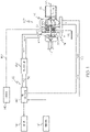
- FIG. 1 is a schematic view of an example e-boosting device 100 according to example embodiments of the present disclosure.
- the e-boosting device 100 may be incorporated within a fuel cell system 102 of a vehicle.
- the e-boosting device 100 may include an e-charger housing 104 and a rotor 106 (i.e., a rotating group).
- the rotor 106 may be supported for rotation by one or more bearings within the e-charger housing 104 about an axis of rotor rotation 108.
- the e-boosting device 100 may include a motor section 110.
- the motor section 110 may include an electric motor 222 that selectively drives the rotor 106 in rotation about the axis 108.
- the e-boosting device 100 may also include a compressor section 111 with a compressor wheel that is fixed to the rotor 106 and that rotates within the housing 104 (within a compressor housing member). As a result of rotation of the rotor 106, the compressor section 111 of the e-boosting device 100 may compress a received input air stream 112 into a pressurized air stream 114. This pressurized air stream 114 may be directed to the fuel cell system 102.
- the e-boosting device 100 may also include a turbine section 116.
- the turbine section 116 may include a turbine wheel that is fixed an end of the rotor 106 that is opposite the compressor section 111, and this turbine wheel may rotate within the housing 104 (within a turbine housing member).
- the turbine section 116 may be configured to receive a high-pressure and high-temperature exhaust gas stream 118 from the fuel cell system 102.
- the turbine section 116 may transfer and/or convert energy of the exhaust gas stream 118.
- the turbine section 116 may drive the rotor 106 to drive rotation of the compressor section 111.
- the turbine section 116 may be operatively connected to an electric generator for generating electrical energy for the motor section 110.
- the high-pressure exhaust gas stream 118 may become a lower-pressure exhaust gas stream 124 that is released into a downstream exhaust pipe 126.
- the pressurized air stream 114 may be characterized by an increased temperature, over that of the input air stream 112. Accordingly, the air stream 114 may be channeled through an air cooler 130 (i.e., an intercooler), such as a convectively cooled charge air cooler.
- the air cooler 130 may be configured to dissipate heat from the air stream 114, increasing its density.
- the resulting cooled and pressurized air stream 132 may be channeled to a fuel cell stack 140, or alternatively, into a subsequent-stage, in-series compressor.
- Hydrogen may be supplied to the fuel cell stack 140 from a tank 142, and oxygen may be supplied to the fuel cell stack 140 to generate electricity by a known chemical reaction.
- the fuel cell stack 140 may generate electricity for an electrical device, such as an electric motor 144.
- a control system 145 may be included for controlling the various systems.
- the control system 145 may be connected to one or more components via communication connection(s) 149.
- the control system 145 may be a computerized system with a processor, various sensors, and other components for electrically controlling operation of the motor 144, the fuel cell stack 140, and/or the e-boosting device 100.
- the fuel cell system 102 may be included in a vehicle, such as a car, truck, sport utility vehicle, van, motorcycle, etc. Therefore, in some embodiments, the electric motor 144 may convert the electrical power to mechanical power to drive and rotate an axle (and, thus, one or more wheels) of the vehicle.
- the control system 145 may be incorporated within a vehicle control unit, which controls a number of additional vehicle systems (e.g., braking systems, air-conditioning systems, etc.).
- oxygen may be provided to the fuel cell stack 140, at least in part, by the e-boosting device 100 as represented in FIG. 1 .
- the motor section 110 may drive rotation of the rotor 106, and the compressor section 111 may provide the pressurized air stream 114 to the air cooler 130 as it flows to the stack 140, and the exhaust gas stream 118 from the stack 140 may be fed back to the turbine section 116 for providing power assist to the motor section 110.
- the turbine section 116 may be omitted such that the e-boosting device 100 includes the motor section 110 as well as the compressor section 111.
- the e-boosting device 100 may include a plurality of sections, such as a plurality of compressor sections that are fluidly connected in succession to include a first (low pressure) stage that feeds a second (high pressure) stage that ultimately feeds the fuel cell system 102.
- the e-boosting device 100 may be provided in systems other than the fuel cell system 102 without departing from the scope of the present disclosure.
- e-boosting device as used herein is to be interpreted broadly, for example, to include devices with an electrically driven compressor wheel regardless of where the e-boosting device is incorporated, the type of system in which the e-boosting device is incorporated, etc. It will also be appreciated that the e-boosting device of the present disclosure may also be referred to as an electrically driven compressor assembly. Also, the e-boosting device of the present disclosure may be configured as an electric supercharger, as a hybrid turbocharger, as an e-charger device, e-turbo, or other related component.
- the motor section 110 may include the motor 222 as mentioned above.
- the motor 222 may include a stator 224 and a rotor member 226.
- the rotor member 226 may be fixed to the shaft of the rotor 106, and the rotor member 226 may be received within the stator 224 and may be operatively connected such that the rotor 106 is selectively driven in rotation by the motor 222.
- the motor 222 may be encased within a motor case 228 ( FIGS. 2 , 3, and 4 ).
- the motor case 228 may be a hollow, shell-like, thin-walled body.
- the motor case 228 may include an interior motor cavity 230 therein.
- the size and dimensions of the motor cavity 230 may correspond to that of the motor 222 to be nested and supported therein.
- the shaft of the rotor 106 may extend and project out from opposite sides of the motor case 228. Otherwise, the motor case 228 may substantially house, encapsulate, and support the motor 222.
- the motor case 228 may be cylindrical and/or or barrel-shaped.
- the motor case 228 may include a first end 201 and a second end 202 that extend transverse to the axis 108 and that are spaced apart from each other along the axis 108.
- the motor case 228 may further include a side 203 that extends about the axis 108 in a circumferential direction. The side 203 may also extend longitudinally between the first end 201 and the second end 202.
- an "outboard direction" will be discussed relative to the motor case 228.
- the outboard direction can be directed longitudinally (i.e., substantially parallel to the axis) away from the first end 201 and away from the motor cavity 230.
- the outboard direction can be directed longitudinally (i.e., substantially parallel to the axis) away from the second end 202 and away from the motor cavity 230.
- the outboard direction can be directed radially away from the side 203 of the motor case 228.
- the motor case 228 may define an inboard direction that is directed toward the motor case 228 and the motor cavity 230 therein.
- the inboard direction is directed longitudinally into the motor cavity 230.
- the inboard direction is directed radially toward the side 203 of the motor case 228 and into the motor cavity 230.
- the motor case 228 may be received and fixedly supported within an outer housing 204.
- the outer housing 204 may define part of the housing 104 of the e-boosting device 100.
- the outer housing 204 may include one or more strong and robust (e.g., metallic) parts.
- the outer housing 204 may be block-like with an outer housing cavity 206 that is substantially cylindrical or barrel-shaped.
- the outer housing cavity 206 may be defined by a first face 208, a second face 209, and a side face 210.
- the motor case 228 may be received within the outer housing cavity 206 such that the first end 201 opposes the first face 208, the second end 202 opposes the second face 209, and the side 203 opposes the side face 210.
- the e-boosting device 100 may include a cooling system 250 ( FIGS. 2 and 6-8 ).
- the cooling system 250 may include a plurality of fluid channels, reservoirs, passages, circuits, etc. that receive one or more flows of liquid coolant.
- the cooling system 250 may include at least one inlet, such as a first inlet 212 and a second inlet 213 ( FIG. 2 ).
- the cooling system 250 may further include a coolant jacket 214.
- the coolant jacket 214 may be cooperatively defined by the motor case 228 and the outer housing 204 so as to surround the motor case 228. Stated differently, a majority of the exterior of the motor case 228 may be smaller than the interior surface of the outer housing cavity 206.
- the exterior of the motor case 228 may be spaced away and separated at a distance from the interior surface of the outer housing cavity 206.
- the space between the exterior of the motor case 228 and the interior surface of the outer housing cavity 206 may define the coolant jacket 214.
- the cooling system 250 may additionally include at least one outlet 216 ( FIG. 7 ).
- liquid coolant may be provided via the inlets 212, 213 to the coolant jacket 214, and this coolant may be discharged via the outlet 216. As the coolant flows through the cooling system 250, the coolant may remove heat from the e-boosting device 100 to maintain high operating efficiency.
- the motor case 228 may include a plurality of pieces, parts, members, etc. that cooperatively define the motor case 228 and the motor cavity 230 therein.
- the motor case 228 may generally include a first casing member 231 and a second casing member 232, which are fixed together (e.g., removably attached) end-to-end so as to cooperatively define the motor case 228 and the motor cavity 230 therein.
- the first casing member 231 may be referred to as a "sleeve” and the second casing member 232 may be referred to as a "cap” for the motor 222 in some embodiments.
- the first casing member 231 may include a first shell member 234. As shown in FIG. 5 , the first shell member 234 may be unitary, cup-shaped, and thin-walled (e.g., as low as one millimeter wall thickness).
- the first shell member 234 may include a circular and plate-like end disc 238 ( FIG. 5 ) and an annular ring 240 fixed thereto.
- the annular ring 240 may include one or more features (e.g., tapered sections, shoulders, edges, or other surface features) that vary the diameter of the annular ring 240 as it projects from the disc 238.
- the end disc 238 may include a central aperture 242.
- the ring 240 may project from one side of the end disc 238 and terminate at a rim 244.
- the rim 244 may have a slightly larger diameter than the end disc 238.
- the first casing member 231 may include at least one first dam member 236.
- the first dam member(s) 236 may be fixed to the first shell member 234.
- the first dam member(s) 236 may be layered on and fixed to an outer surface of the first shell member 234.
- the first dam member(s) 236 may also project in the outboard direction from the outer surface of the first shell member 234.
- the first dam member(s) 236 may be referred to as "projecting portions" or "outboard parts” that project from the shell member(s) 234 in the outboard direction.
- the first dam members 236 may include a first circumferential dam 246, which is layered on the outer surface of the first shell member 234, and which extends in the circumferential direction thereon.
- the first circumferential dam 246 may be disposed proximate the rim 244.
- the first dam members 236 may also include a second circumferential dam 248.
- the second circumferential dam 248 may be layered on the outer surface of the first shell member 234 and may extend in the circumferential direction thereon.
- the second circumferential dam 248 may be disposed proximate the transition between the rim 244 and the end disc 238.
- the first dam members 236 may include an elongate dam 249.
- the elongate dam 249 may include a plurality of elongate and straight segments, such as a first segment 245 that extends longitudinally along the annular ring 240, and a second segment 247 that extends radially along the end disc 238. As shown in FIGS. 4 and 5 , there may be a space 254 defined circumferentially between the elongate dam 249 and a terminal end of the second circumferential dam 248.
- the first shell member 234 and the first dam members 236 may be made from different materials.
- the first shell member 234 may be made from a metallic material
- the first dam members 236 may be made from a polymeric material.
- the first shell member 234 and dam members 236 may both be made from a metallic material or, alternatively, both made from a polymeric material.
- the first shell member 234 and dam members 236 may be made from the same material and may define a unitary, one-part member.
- the second casing member 232 may include a second shell member 264.
- the second shell member 264 may be unitary, cup-shaped, and thin-walled (e.g., as low as one millimeter wall thickness).
- the second shell member 264 may include a circular and plate-like end disc 268 ( FIG. 5 ) and an annular ring 270 fixed thereto.
- the annular ring 270 may have a substantially constant diameter.
- the end disc 268 may include a central aperture 272.
- the ring 270 may project from one side of the end disc 268 and terminate at a rim 274.
- the ring 270 may also include an elongate side opening 276 extending therethrough.
- the second casing member 232 may include at least one second dam member 266.
- the second dam member(s) 266 may be fixed to the second shell member 264.
- the second dam member(s) 266 may be fixed to an outer surface of the second shell member 264.
- the second dam member(s) 266 may also project in the outboard direction from the outer surface of the second shell member 264.
- the second dam member(s) 266 may be referred to as "projecting portions" or "outboard parts” that project from the shell member(s) 264 in the outboard direction.
- the second dam members 266 may include an outer skirt 278, which extends about the ring 270.
- the second dam members 266 may include an end dam 279, which extends radially along the end disc 268.
- the second shell member 264 and the second dam members 266 may be made from different materials.
- the second shell member 264 may be made from a metallic material
- the second dam members 266 may be made from a polymeric material.
- the second shell member 264 and dam members 236 may both be made from a metallic material or, alternatively, both made from a polymeric material.
- the first shell member 234 and dam members 236 may be made from the same material and may define a unitary, one-part member.
- At least one of the first and second casing members 231, 232 may be formed according to embodiments of the present disclosure. For example, both may be formed using a combination of metal forming and overmolding processes.
- the first casing member 231 may be formed by metal forming (e.g., cold working via stamping, pressing, or other similar process) the first shell member 234.
- the first dam members 236 may be overmolded onto the first shell member 234.
- the second casing member 232 may be formed similarly, by metal forming the second shell member 264 and subsequently overmolding the second dam member 266 onto the second shell member 264.
- the skirt 278 may be overmolded to include an opening that aligns with the side opening 276.
- the casing members 231, 232 may also be heat treated, coated, or otherwise treated before further assembly.
- the first and second casing members 231, 232 may be joined and, in some embodiments, removably attached ( FIGS. 3-5 ). As shown in FIG. 5 , the first casing member 231 may be received in the second casing member 232. The rim 244 of the first casing member 231 may be received within the rim 274 of the second casing member 232. The outer radial surface of the rim 244 may be fluidly sealed to the inner radial surface of the rim 274.
- the annular rings 240, 270, the skirt 278, and the first and second circumferential dams 246, 248 may extend about the axis 108 and may define the side 203 of the motor case 228.
- end disc 268 and the end dam 279 may extend radially with respect to the axis 108 and may define the first end 201 of the motor case 228. Furthermore, the end disc 238 and the elongate dam 249 may define the second end 202 of the motor case 228.
- the first and second casing members 231, 232 may be joined and sealed using adhesives, fasteners, an interference fit, or otherwise.
- the motor case 228 may further include and define at least one through-hole, such as a first through-hole 296 ( FIGS. 2-4 and 6 ) and a second through-hole 298 ( FIGS. 3-7 ).
- the through-holes 296, 298 may have any suitable shape and may be referred to as gaps, apertures, or other types of openings that allow the coolant to pass therethrough for flow between one part of the coolant jacket 214 to another.
- the through-holes 296, 298 may be defined independently to have a continuous fluid boundary extending through the motor case 228.
- the through-holes 296, 298 may be define part of the coolant jacket 214 independently from the outer housing 204.
- the skirt 278 may include an attached area 273 that is layered on and attached to the outer surface of the annular ring 270.
- the skirt 278 also projects outwardly in the radial direction from the attached area 273 and may extend about the ring 270.
- the skirt 278 may also include a first detached area 275 and a second detached area 271 that are detached from the ring 270.
- the outer surfaces of the detached area 271, 275 and attached areas 273 of the skirt 278 may be flush as shown in FIGS. 3 and 4 so as to be smooth, continuous, and annular.
- the first detached area 275 may extend from one circumferential end of the attached area 273 to the first segment 245 of the elongate dam 249.
- the first detached area 275 may also be spaced apart in the outboard direction (i.e., the radial direction) from the outer surface of the shell member 264 to define the first through-hole 296 therebetween in the radial direction.
- the first through-hole 296 may extend longitudinally (e.g., substantially parallel to the axis 108) through the motor case 228, between the shell member 264 and the skirt 278.
- the first through-hole 296 may be arcuately shaped so as to extend circumferentially with respect to the axis 108.
- the second detached area 271 may extend from the opposite circumferential end of the attached area 273 to the first segment 245 of the elongate dam 249.
- the second detached area 271 may be spaced apart in the outboard direction (i.e., the radial direction) from the outer surface of the shell member 264 to define the second through-hole 298 therebetween in the radial direction.
- the second through-hole 298 may extend longitudinally (e.g., substantially parallel to the axis 108) through the motor case 228, between the shell member 264 and the skirt 278.
- the second through-hole 298 may be arcuately shaped so as to extend circumferentially with respect to the axis 108.
- the motor case 228 may be received in the outer housing 204.
- the motor case 228 may be nested therein with: 1) outer surfaces of the first and second dam members 236, 266 ( FIGS. 3-5 ) lying adjacent the opposing inner faces 208, 209, 210 of the outer housing cavity 206; and 2) outer surface of the first and second shell members 234, 264 spaced apart at a distance from the opposing inner faces 208, 209, 210 of the outer housing cavity 206.
- the coolant jacket 214 may be at least partly defined by the space between the outer surface of the shell members 234, 264 and the inner faces 208, 209, 210 of the outer housing cavity 206. Fluid from the inlets 212, 213 ( FIG. 2 ) can flow through this space to the outlet 216 ( FIG. 7 ).
- the first and second dam members 236, 266 may partition the coolant jacket 214 such that coolant is directed to low primarily along a predetermined path through the coolant jacket 214.
- the e-boosting device 100 may include one or more sealing members.
- the sealing members may be independent parts that are sealed to the motor case 228 and/or to the outer housing 204.
- the sealing members may, thus, further partition the coolant jacket 214.
- the assembly 100 may include a first sealing member 280 ( FIGS. 2 , 7, and 8 ).
- the first sealing member 280 may be a polymeric O-ring that is centered on the axis 108, and which may be disposed between and sealed to the end disc 238 and the face 209.
- the face 209 may include a groove that receives the first sealing member 280.
- the assembly 100 may additionally include a second sealing member 282.
- the second sealing member 282 may be a polymeric O-ring that is centered on the axis 108, and which may be disposed between and sealed to the outer radial surface of the skirt 278 and the side face 210.
- the outer skirt 278 may include a groove 284 that receives the second sealing member 282.
- the assembly 100 may additionally include a third sealing member 286.
- the third sealing member 286 may be a polymeric O-ring that is centered on the axis 108, and which may be disposed between and sealed to the end surface of the skirt 278 and the face 208 of the outer housing 204.
- the face 208 may include a groove that receives the third sealing member 286.
- the assembly 100 may additionally include a fourth sealing member 288 ( FIGS. 2 and 7 ).
- the fourth sealing member 288 may be a polymeric O-ring that is centered on the axis 108, and which may be disposed between and sealed to the end disc 268 and the face 208. As shown in FIG. 7 , the face 208 may include a groove that receives the fourth sealing member 288.
- one or more continuous fluid pathways may be defined through the coolant jacket 214 from the inlets 212, 213 to the outlet 216. As illustrated, there may be a plurality of pathways that flow in-parallel through the coolant jacket 214 as will be discussed.
- a first coolant flow path (i.e., a circumferential flow path) may be defined. Coolant from the inlet 212 ( FIG. 2 ) may be provided to a first inlet area 290 ( FIGS. 2 and 4 ) and then to a side chamber 281 of the coolant jacket 214.
- the side chamber 281 may surround the side 203 of the motor case 228.
- the side chamber 281 may be collectively defined by the first circumferential dam 246, the skirt 278, the elongate dam 249, the outer surface of the first shell member 234, and the face 210 of the outer housing 204.
- Fluid in the side chamber 281 may flow circumferentially about the motor case 228 to an outlet area 292 on the opposite side of the elongate dam 249 ( FIGS. 4 and 7 ).
- This outlet area 292 may be fluidly connected to the outlet 216 ( FIG. 7 ) for discharging this coolant.
- a second coolant flow path (i.e., a first end flow path) may be defined. Coolant from the inlet 213 ( FIG. 2 ) may be provided to a second inlet area 294 and then to a first end chamber 283 of the coolant jacket 214.
- the first end chamber 283 may surround the end 202 of the motor case 228.
- the first end chamber 283 may be collectively defined by the second circumferential dam 248, the second segment 247 of the elongate dam 249, the first sealing member 280, the end disc 238, and the face 209. Fluid in the first end chamber 283 may flow circumferentially about the motor case 228 to the space 254 ( FIG. 4 ) and, then, to the outlet area 292 for coolant discharge.
- a third coolant flow path (i.e., a second end flow path) may be defined.
- the first through-hole 296 of the motor case 228 may fluidly connect the side chamber 281 to a second end chamber 285 of the coolant jacket 214.
- the second end chamber 285 may surround the end 201 of the motor case 228.
- the second end chamber 285 may be collectively defined by the skirt 278, the sealing member 288, the outer surface of the end disc 268, and the face 208 of the second shell member 264.
- coolant that is inlet via the first inlet 212 may flow through the first through-hole 296 and into the second end chamber 285. This fluid may flow circumferentially about the end disc 268 toward the second through-hole 298.
- the second through-hole 298 may fluidly connect and outlet the second end chamber 285 to the outlet area 292 of the side chamber 281 of the coolant jacket 214 to discharge via the outlet 216.
- cooling system 250 provides effective cooling.
- the cooling system 250, the motor case 228, and more generally the e-boosting device 100 is highly compact and lightweight as well.
- the e-boosting device 100 may be manufactured efficiently as well.
- the through-holes 296, 298 through the motor case 228 provide useful routing of the coolant through the coolant jacket 214.
- the through-holes 296, 298 may be formed easily for routing the coolant.
- Various through-hole configurations may be included in additional embodiments as well. Through-holes may extend radially in some embodiments, at an angle relative to the axis 108, or along a nonlinear axis. These different variations can be included using efficient manufacturing methods as well, thereby providing a strong, chemically-resistant, nonmagnetic motor case 228.
Landscapes
- Engineering & Computer Science (AREA)
- Power Engineering (AREA)
- Mechanical Engineering (AREA)
- General Engineering & Computer Science (AREA)
- Manufacturing & Machinery (AREA)
- Physics & Mathematics (AREA)
- Thermal Sciences (AREA)
- Chemical & Material Sciences (AREA)
- Combustion & Propulsion (AREA)
- Motor Or Generator Cooling System (AREA)
- Motor Or Generator Frames (AREA)
- Chemical Kinetics & Catalysis (AREA)
- General Chemical & Material Sciences (AREA)
Abstract
A motor assembly for an e-boosting device is disclosed. The motor assembly includes a motor case and a motor cavity within the motor case. The motor case is configured to receive an electric motor that is configured to drivingly rotate a rotor about an axis of rotation. The motor assembly also includes a through-hole defined by the motor case. The motor case configured to be received in an outer housing to cooperatively define a coolant jacket with the outer housing. The coolant jacket includes a fluid flow path defined partly by the through-hole. Methods of manufacturing the motor assembly are also disclosed.
Description
- The present disclosure generally relates to an e-boosting device and, more particularly, relates to a motor cooling system for an e-boosting device.
- Charging devices, such as turbochargers or superchargers, are provided that boost performance by compressing a fluid that is then fed to a fuel cell stack, an engine, etc. In some cases, an e-boosting device is provided that has an electric motor configured to drive and rotate a compressor wheel for compressing an airflow, which is then fed to the fuel cell stack, the engine, etc.
- These charging devices may include a cooling system. In the case of an e-boosting device, for example, a cooling system may be provided that directs flow of a coolant through the device to maintain operating temperatures within a predetermined range. The electric motor may be cooled, for example, to improve operating efficiency of the motor.
- However, conventional cooling systems for e-boosting devices suffer from various deficiencies, and operating efficiency may be negatively affected as a result. It may be difficult to provide an acceptable cooling effect for some charging devices and/or under certain operating conditions. There may be space constraints that limit the size and/or routing of the cooling circuit, which can negatively affect cooling performance.
- Thus, it is desirable to provide a cooling system for an e-boosting device that improves the cooling effect and/or operating efficiency. It is also desirable to provide an e-charger cooling system that is compact, highly manufacturable, and that is cost effective. Other desirable features and characteristics of the present disclosure will become apparent from the subsequent detailed description and the appended claims, taken in conjunction with the accompanying drawings and this background discussion.
- In one embodiment, a motor assembly for an e-boosting device is disclosed. The motor assembly includes a motor case and a motor cavity within the motor case. The motor case is configured to receive an electric motor that is configured to drivingly rotate a rotor about an axis of rotation. The motor assembly also includes a through-hole defined by the motor case. The motor case configured to be received in an outer housing to cooperatively define a coolant jacket with the outer housing. The coolant jacket includes a fluid flow path defined partly by the through-hole.
- In another embodiment, an e-boosting device is disclosed that includes a method of manufacturing an e-boosting device. The method includes providing an electric motor that is configured to drivingly rotate a rotor. The method also includes encasing the electric motor within a motor cavity of a motor case. The motor case defines a through-hole. Furthermore, the method includes disposing the motor cavity within an outer housing to define a coolant jacket of a cooling system. The coolant jacket is cooperatively defined by the outer housing and the motor case. The coolant jacket includes a fluid passage defined by the through-hole.
- The present disclosure will hereinafter be described in conjunction with the following drawing figures, wherein like numerals denote like elements, and wherein:
-
FIG. 1 is a schematic illustration of an e-boosting device incorporated, for example, in a fuel cell system; -
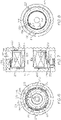
FIG. 2 is a cross-sectional view of a motor section of the e-boosting device according to example embodiments of the present disclosure; -
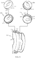
FIG. 3 is a first isometric view of a motor case of the motor section ofFIG. 2 according to example embodiments of the present disclosure; -
FIG. 4 is a second isometric view of the motor case ofFIG. 2 ; -
FIG. 5 is an exploded view of the motor case ofFIGS. 3 and 4 ; -
FIG. 6 is a first end view of a cooling system, which is partly defined by the motor case ofFIG. 3 ; -
FIG. 7 is a cross-sectional view of the cooling system ofFIG. 6 ; and -
FIG. 8 is a second end view of the cooling system ofFIG. 6 . - The following detailed description is merely exemplary in nature and is not intended to limit the present disclosure or the application and uses of the present disclosure. Furthermore, there is no intention to be bound by any theory presented in the preceding background or the following detailed description.
- Broadly, example embodiments disclosed herein include an improved e-boosting device. The disclosed e-boosting device may be a device with an electrically driven compressor wheel that provides a compressed airstream to a downstream component (e.g., an engine, a fuel cell stack, etc.). Also, the e-boosting device of the present disclosure may be configured as an electrically assisted turbocharger, an electric supercharger, as a hybrid turbocharger, as an e-charger assembly, e-turbo, e-assist charging device, or other related component. In particular, an e-boosting device and methods of manufacturing the same are disclosed, wherein the e-boosting device also includes a fluid cooling system through which a coolant (e.g., ethylene glycol) flows for removing heat from the e-boosting device.
- The e-boosting device may include a motor case, which encases an electric motor and holds core windings together. At least part of the motor case may be heat conductive for transferring heat from the motor to the coolant. The motor case may have relatively thin wall thickness (especially compared with conventional motor cases) such that mass is reduced, material costs are reduced, and such that heat is transferred quickly and efficiently therethrough to the coolant. Materials for the motor case may be chosen to be chemically resistant to the coolant and non-magnetic to avoid interference with motor operations. The motor case may also define one or more fluid boundaries, barriers, partitions, dams, etc. for directing the coolant flow through the cooling system. The motor case may be compact, manufactured efficiently, and can provide additional advantages as discussed below.
- There may be a plurality of casing members that cooperatively define the motor case and that cooperatively encapsulate the motor. In some embodiments, there may be a first casing member and a second casing member. At least one of the casing members may span over and cover over the stator of the motor, and at least part of the casing member may include a barrier, dam, partition, or other member that projects therefrom. This barrier member may partition the coolant system and may direct the coolant therethrough.
- The motor case may encapsulate the motor with a rotor shaft extending outward therefrom. Also, the motor case may be positioned within an outer housing of the e-boosting device. A coolant jacket may be defined between and cooperatively defined by the inner surface of the outer housing and the outer surface of the motor case.
- Furthermore, in some embodiments, the motor case may be formed to include or at least partly define a hole therethrough. The hole may be a gap, aperture, or other void that is independently defined through motor case. This hole, etc. may define a fluid passage for the coolant to flow from one area of the coolant jacket to another. In other words, the hole may fluidly connect these areas of the coolant jacket.
- In some embodiments, the motor case may include a shell portion that covers over the stator and a projecting portion that projects outboard from the shell portion. The projecting portion may partition the coolant jacket (i.e., separate one area of the coolant jacket from another, dam the coolant, and/or direct the flow of coolant through the coolant jacket). The hole in the motor case may be defined at least partly by the projecting portion of the motor case such that coolant is able to flow through the projecting portion. In some embodiments, the hole may be defined between the projecting portion and the shell portion.
- Accordingly, coolant may flow from an inlet, into and through the coolant jacket, and to an outlet to remove heat (e.g., from the stator of the motor, from the housing, from the casing, from one or more bearing components, or from other areas proximate the coolant jacket). The coolant may be directed through the hole in the motor case as it flows through the coolant jacket for effectively removing heat from the e-boosting device. A plurality of cooling passages may be defined with a predetermined shape, size, and flow profile in order to provide the desired flow of the coolant. Additionally, manufacturing methods of the present disclosure can be employed for forming the motor case efficiently, accurately, and repeatably in a high-volume manufacturing environment.
-
FIG. 1 is a schematic view of an examplee-boosting device 100 according to example embodiments of the present disclosure. In some embodiments, thee-boosting device 100 may be incorporated within afuel cell system 102 of a vehicle. - Generally, the
e-boosting device 100 may include ane-charger housing 104 and a rotor 106 (i.e., a rotating group). Therotor 106 may be supported for rotation by one or more bearings within thee-charger housing 104 about an axis ofrotor rotation 108. - The
e-boosting device 100 may include amotor section 110. Themotor section 110 may include anelectric motor 222 that selectively drives therotor 106 in rotation about theaxis 108. - The
e-boosting device 100 may also include acompressor section 111 with a compressor wheel that is fixed to therotor 106 and that rotates within the housing 104 (within a compressor housing member). As a result of rotation of therotor 106, thecompressor section 111 of thee-boosting device 100 may compress a receivedinput air stream 112 into apressurized air stream 114. Thispressurized air stream 114 may be directed to thefuel cell system 102. - The
e-boosting device 100 may also include aturbine section 116. Theturbine section 116 may include a turbine wheel that is fixed an end of therotor 106 that is opposite thecompressor section 111, and this turbine wheel may rotate within the housing 104 (within a turbine housing member). Theturbine section 116 may be configured to receive a high-pressure and high-temperatureexhaust gas stream 118 from thefuel cell system 102. - The
turbine section 116 may transfer and/or convert energy of theexhaust gas stream 118. For example, theturbine section 116 may drive therotor 106 to drive rotation of thecompressor section 111. In additional embodiments, theturbine section 116 may be operatively connected to an electric generator for generating electrical energy for themotor section 110. The high-pressureexhaust gas stream 118 may become a lower-pressureexhaust gas stream 124 that is released into adownstream exhaust pipe 126. - From the
compressor section 111, thepressurized air stream 114 may be characterized by an increased temperature, over that of theinput air stream 112. Accordingly, theair stream 114 may be channeled through an air cooler 130 (i.e., an intercooler), such as a convectively cooled charge air cooler. Theair cooler 130 may be configured to dissipate heat from theair stream 114, increasing its density. The resulting cooled andpressurized air stream 132 may be channeled to afuel cell stack 140, or alternatively, into a subsequent-stage, in-series compressor. - Hydrogen may be supplied to the
fuel cell stack 140 from atank 142, and oxygen may be supplied to thefuel cell stack 140 to generate electricity by a known chemical reaction. Thefuel cell stack 140 may generate electricity for an electrical device, such as anelectric motor 144. - A
control system 145 may be included for controlling the various systems. Thecontrol system 145 may be connected to one or more components via communication connection(s) 149. Thecontrol system 145 may be a computerized system with a processor, various sensors, and other components for electrically controlling operation of themotor 144, thefuel cell stack 140, and/or thee-boosting device 100. Also, thefuel cell system 102 may be included in a vehicle, such as a car, truck, sport utility vehicle, van, motorcycle, etc. Therefore, in some embodiments, theelectric motor 144 may convert the electrical power to mechanical power to drive and rotate an axle (and, thus, one or more wheels) of the vehicle. In these embodiments, thecontrol system 145 may be incorporated within a vehicle control unit, which controls a number of additional vehicle systems (e.g., braking systems, air-conditioning systems, etc.). - Thus, during operations, oxygen may be provided to the
fuel cell stack 140, at least in part, by thee-boosting device 100 as represented inFIG. 1 . More specifically, themotor section 110 may drive rotation of therotor 106, and thecompressor section 111 may provide thepressurized air stream 114 to theair cooler 130 as it flows to thestack 140, and theexhaust gas stream 118 from thestack 140 may be fed back to theturbine section 116 for providing power assist to themotor section 110. It will be appreciated, however, that other embodiments of thee-boosting device 100 fall within the scope of the present disclosure. For example, in some embodiments, theturbine section 116 may be omitted such that thee-boosting device 100 includes themotor section 110 as well as thecompressor section 111. Additionally, in some embodiments, thee-boosting device 100 may include a plurality of sections, such as a plurality of compressor sections that are fluidly connected in succession to include a first (low pressure) stage that feeds a second (high pressure) stage that ultimately feeds thefuel cell system 102. Moreover, thee-boosting device 100 may be provided in systems other than thefuel cell system 102 without departing from the scope of the present disclosure. - It will be appreciated that the term "e-boosting device" as used herein is to be interpreted broadly, for example, to include devices with an electrically driven compressor wheel regardless of where the e-boosting device is incorporated, the type of system in which the e-boosting device is incorporated, etc. It will also be appreciated that the e-boosting device of the present disclosure may also be referred to as an electrically driven compressor assembly. Also, the e-boosting device of the present disclosure may be configured as an electric supercharger, as a hybrid turbocharger, as an e-charger device, e-turbo, or other related component.
- Referring now to
FIG. 2 , themotor section 110 is shown in greater detail according to example embodiments. Themotor section 110 may include themotor 222 as mentioned above. Themotor 222 may include astator 224 and arotor member 226. Therotor member 226 may be fixed to the shaft of therotor 106, and therotor member 226 may be received within thestator 224 and may be operatively connected such that therotor 106 is selectively driven in rotation by themotor 222. - The
motor 222 may be encased within a motor case 228 (FIGS. 2 ,3, and 4 ). Generally, themotor case 228 may be a hollow, shell-like, thin-walled body. Thus, themotor case 228 may include aninterior motor cavity 230 therein. The size and dimensions of themotor cavity 230 may correspond to that of themotor 222 to be nested and supported therein. The shaft of therotor 106 may extend and project out from opposite sides of themotor case 228. Otherwise, themotor case 228 may substantially house, encapsulate, and support themotor 222. - Generally, the
motor case 228 may be cylindrical and/or or barrel-shaped. Themotor case 228 may include afirst end 201 and asecond end 202 that extend transverse to theaxis 108 and that are spaced apart from each other along theaxis 108. Themotor case 228 may further include aside 203 that extends about theaxis 108 in a circumferential direction. Theside 203 may also extend longitudinally between thefirst end 201 and thesecond end 202. - For reference purposes, an "outboard direction" will be discussed relative to the
motor case 228. For example, in the illustrated embodiments, the outboard direction can be directed longitudinally (i.e., substantially parallel to the axis) away from thefirst end 201 and away from themotor cavity 230. Furthermore, the outboard direction can be directed longitudinally (i.e., substantially parallel to the axis) away from thesecond end 202 and away from themotor cavity 230. Furthermore, the outboard direction can be directed radially away from theside 203 of themotor case 228. - Conversely, the
motor case 228 may define an inboard direction that is directed toward themotor case 228 and themotor cavity 230 therein. The inboard direction is directed longitudinally into themotor cavity 230. Furthermore, the inboard direction is directed radially toward theside 203 of themotor case 228 and into themotor cavity 230. - As shown in
FIG. 2 , themotor case 228 may be received and fixedly supported within anouter housing 204. Theouter housing 204 may define part of thehousing 104 of thee-boosting device 100. Theouter housing 204 may include one or more strong and robust (e.g., metallic) parts. Theouter housing 204 may be block-like with anouter housing cavity 206 that is substantially cylindrical or barrel-shaped. As shown inFIG. 2 , theouter housing cavity 206 may be defined by afirst face 208, asecond face 209, and aside face 210. Themotor case 228 may be received within theouter housing cavity 206 such that thefirst end 201 opposes thefirst face 208, thesecond end 202 opposes thesecond face 209, and theside 203 opposes theside face 210. - Furthermore, the
e-boosting device 100 may include a cooling system 250 (FIGS. 2 and6-8 ). Thecooling system 250 may include a plurality of fluid channels, reservoirs, passages, circuits, etc. that receive one or more flows of liquid coolant. Thecooling system 250 may include at least one inlet, such as afirst inlet 212 and a second inlet 213 (FIG. 2 ). Thecooling system 250 may further include acoolant jacket 214. Thecoolant jacket 214 may be cooperatively defined by themotor case 228 and theouter housing 204 so as to surround themotor case 228. Stated differently, a majority of the exterior of themotor case 228 may be smaller than the interior surface of theouter housing cavity 206. As such, the exterior of themotor case 228 may be spaced away and separated at a distance from the interior surface of theouter housing cavity 206. The space between the exterior of themotor case 228 and the interior surface of theouter housing cavity 206 may define thecoolant jacket 214. Thecooling system 250 may additionally include at least one outlet 216 (FIG. 7 ). In some embodiments, liquid coolant may be provided via theinlets coolant jacket 214, and this coolant may be discharged via theoutlet 216. As the coolant flows through thecooling system 250, the coolant may remove heat from thee-boosting device 100 to maintain high operating efficiency. - Referring now to
FIGS. 3-5 , themotor case 228 will be discussed in detail according to example embodiments. In some embodiments, themotor case 228 may include a plurality of pieces, parts, members, etc. that cooperatively define themotor case 228 and themotor cavity 230 therein. For example, themotor case 228 may generally include afirst casing member 231 and asecond casing member 232, which are fixed together (e.g., removably attached) end-to-end so as to cooperatively define themotor case 228 and themotor cavity 230 therein. Thefirst casing member 231 may be referred to as a "sleeve" and thesecond casing member 232 may be referred to as a "cap" for themotor 222 in some embodiments. - The
first casing member 231 may include afirst shell member 234. As shown inFIG. 5 , thefirst shell member 234 may be unitary, cup-shaped, and thin-walled (e.g., as low as one millimeter wall thickness). Thefirst shell member 234 may include a circular and plate-like end disc 238 (FIG. 5 ) and anannular ring 240 fixed thereto. Theannular ring 240 may include one or more features (e.g., tapered sections, shoulders, edges, or other surface features) that vary the diameter of theannular ring 240 as it projects from thedisc 238. Theend disc 238 may include acentral aperture 242. Thering 240 may project from one side of theend disc 238 and terminate at arim 244. Therim 244 may have a slightly larger diameter than theend disc 238. - Also, the
first casing member 231 may include at least onefirst dam member 236. The first dam member(s) 236 may be fixed to thefirst shell member 234. The first dam member(s) 236 may be layered on and fixed to an outer surface of thefirst shell member 234. The first dam member(s) 236 may also project in the outboard direction from the outer surface of thefirst shell member 234. Thus, the first dam member(s) 236 may be referred to as "projecting portions" or "outboard parts" that project from the shell member(s) 234 in the outboard direction. - The
first dam members 236 may include a firstcircumferential dam 246, which is layered on the outer surface of thefirst shell member 234, and which extends in the circumferential direction thereon. The firstcircumferential dam 246 may be disposed proximate therim 244. Thefirst dam members 236 may also include a secondcircumferential dam 248. The secondcircumferential dam 248 may be layered on the outer surface of thefirst shell member 234 and may extend in the circumferential direction thereon. The secondcircumferential dam 248 may be disposed proximate the transition between therim 244 and theend disc 238. Furthermore, thefirst dam members 236 may include anelongate dam 249. Theelongate dam 249 may include a plurality of elongate and straight segments, such as afirst segment 245 that extends longitudinally along theannular ring 240, and asecond segment 247 that extends radially along theend disc 238. As shown inFIGS. 4 and5 , there may be aspace 254 defined circumferentially between theelongate dam 249 and a terminal end of the secondcircumferential dam 248. - In some embodiments, the
first shell member 234 and thefirst dam members 236 may be made from different materials. For example, in some embodiments, thefirst shell member 234 may be made from a metallic material, whereas thefirst dam members 236 may be made from a polymeric material. However, it will be appreciated that, in other embodiments, thefirst shell member 234 anddam members 236 may both be made from a metallic material or, alternatively, both made from a polymeric material. Furthermore, in some embodiments, thefirst shell member 234 anddam members 236 may be made from the same material and may define a unitary, one-part member. - The
second casing member 232 may include asecond shell member 264. As shown inFIG. 5 , thesecond shell member 264 may be unitary, cup-shaped, and thin-walled (e.g., as low as one millimeter wall thickness). Thesecond shell member 264 may include a circular and plate-like end disc 268 (FIG. 5 ) and anannular ring 270 fixed thereto. Theannular ring 270 may have a substantially constant diameter. Theend disc 268 may include acentral aperture 272. Thering 270 may project from one side of theend disc 268 and terminate at arim 274. Thering 270 may also include anelongate side opening 276 extending therethrough. - Also, the
second casing member 232 may include at least onesecond dam member 266. The second dam member(s) 266 may be fixed to thesecond shell member 264. The second dam member(s) 266 may be fixed to an outer surface of thesecond shell member 264. The second dam member(s) 266 may also project in the outboard direction from the outer surface of thesecond shell member 264. Thus, the second dam member(s) 266 may be referred to as "projecting portions" or "outboard parts" that project from the shell member(s) 264 in the outboard direction. - The
second dam members 266 may include anouter skirt 278, which extends about thering 270. Thesecond dam members 266 may include anend dam 279, which extends radially along theend disc 268. - In some embodiments, the
second shell member 264 and thesecond dam members 266 may be made from different materials. For example, in some embodiments, thesecond shell member 264 may be made from a metallic material, whereas thesecond dam members 266 may be made from a polymeric material. However, it will be appreciated that, in other embodiments, thesecond shell member 264 anddam members 236 may both be made from a metallic material or, alternatively, both made from a polymeric material. Furthermore, in some embodiments, thefirst shell member 234 anddam members 236 may be made from the same material and may define a unitary, one-part member. - At least one of the first and
second casing members first casing member 231 may be formed by metal forming (e.g., cold working via stamping, pressing, or other similar process) thefirst shell member 234. Then, thefirst dam members 236 may be overmolded onto thefirst shell member 234. Furthermore, thesecond casing member 232 may be formed similarly, by metal forming thesecond shell member 264 and subsequently overmolding thesecond dam member 266 onto thesecond shell member 264. Theskirt 278 may be overmolded to include an opening that aligns with theside opening 276. Thecasing members - The first and
second casing members FIGS. 3-5 ). As shown inFIG. 5 , thefirst casing member 231 may be received in thesecond casing member 232. Therim 244 of thefirst casing member 231 may be received within therim 274 of thesecond casing member 232. The outer radial surface of therim 244 may be fluidly sealed to the inner radial surface of therim 274. Thus, theannular rings skirt 278, and the first and secondcircumferential dams axis 108 and may define theside 203 of themotor case 228. Also, theend disc 268 and theend dam 279 may extend radially with respect to theaxis 108 and may define thefirst end 201 of themotor case 228. Furthermore, theend disc 238 and theelongate dam 249 may define thesecond end 202 of themotor case 228. The first andsecond casing members - The
motor case 228 may further include and define at least one through-hole, such as a first through-hole 296 (FIGS. 2-4 and6 ) and a second through-hole 298 (FIGS. 3-7 ). The through-holes coolant jacket 214 to another. The through-holes motor case 228. Thus, while some of thecoolant jacket 214 may be cooperatively defined by themotor case 228 and theouter housing 204, the through-holes coolant jacket 214 independently from theouter housing 204. - In some embodiments represented in
FIG. 3 , theskirt 278 may include an attachedarea 273 that is layered on and attached to the outer surface of theannular ring 270. Theskirt 278 also projects outwardly in the radial direction from the attachedarea 273 and may extend about thering 270. Theskirt 278 may also include a firstdetached area 275 and a seconddetached area 271 that are detached from thering 270. The outer surfaces of thedetached area areas 273 of theskirt 278 may be flush as shown inFIGS. 3 and 4 so as to be smooth, continuous, and annular. - The first
detached area 275 may extend from one circumferential end of the attachedarea 273 to thefirst segment 245 of theelongate dam 249. The firstdetached area 275 may also be spaced apart in the outboard direction (i.e., the radial direction) from the outer surface of theshell member 264 to define the first through-hole 296 therebetween in the radial direction. As such, the first through-hole 296 may extend longitudinally (e.g., substantially parallel to the axis 108) through themotor case 228, between theshell member 264 and theskirt 278. Also, the first through-hole 296 may be arcuately shaped so as to extend circumferentially with respect to theaxis 108. - The second
detached area 271 may extend from the opposite circumferential end of the attachedarea 273 to thefirst segment 245 of theelongate dam 249. The seconddetached area 271 may be spaced apart in the outboard direction (i.e., the radial direction) from the outer surface of theshell member 264 to define the second through-hole 298 therebetween in the radial direction. As such, the second through-hole 298 may extend longitudinally (e.g., substantially parallel to the axis 108) through themotor case 228, between theshell member 264 and theskirt 278. Also, the second through-hole 298 may be arcuately shaped so as to extend circumferentially with respect to theaxis 108. - As shown in
FIGS. 2 and6-8 , themotor case 228 may be received in theouter housing 204. Themotor case 228 may be nested therein with: 1) outer surfaces of the first andsecond dam members 236, 266 (FIGS. 3-5 ) lying adjacent the opposing inner faces 208, 209, 210 of theouter housing cavity 206; and 2) outer surface of the first andsecond shell members outer housing cavity 206. - Accordingly, as shown in
FIGS. 2 and6-8 , thecoolant jacket 214 may be at least partly defined by the space between the outer surface of theshell members outer housing cavity 206. Fluid from theinlets 212, 213 (FIG. 2 ) can flow through this space to the outlet 216 (FIG. 7 ). The first andsecond dam members coolant jacket 214 such that coolant is directed to low primarily along a predetermined path through thecoolant jacket 214. - Furthermore, the
e-boosting device 100 may include one or more sealing members. The sealing members may be independent parts that are sealed to themotor case 228 and/or to theouter housing 204. The sealing members may, thus, further partition thecoolant jacket 214. For example, theassembly 100 may include a first sealing member 280 (FIGS. 2 ,7, and 8 ). Thefirst sealing member 280 may be a polymeric O-ring that is centered on theaxis 108, and which may be disposed between and sealed to theend disc 238 and theface 209. As shown inFIG. 7 , theface 209 may include a groove that receives thefirst sealing member 280. Theassembly 100 may additionally include asecond sealing member 282. Thesecond sealing member 282 may be a polymeric O-ring that is centered on theaxis 108, and which may be disposed between and sealed to the outer radial surface of theskirt 278 and theside face 210. As shown inFIGS. 2 and7 , theouter skirt 278 may include agroove 284 that receives thesecond sealing member 282. Furthermore, theassembly 100 may additionally include athird sealing member 286. Thethird sealing member 286 may be a polymeric O-ring that is centered on theaxis 108, and which may be disposed between and sealed to the end surface of theskirt 278 and theface 208 of theouter housing 204. As shown inFIGS. 2 and7 , theface 208 may include a groove that receives thethird sealing member 286. Also, theassembly 100 may additionally include a fourth sealing member 288 (FIGS. 2 and7 ). Thefourth sealing member 288 may be a polymeric O-ring that is centered on theaxis 108, and which may be disposed between and sealed to theend disc 268 and theface 208. As shown inFIG. 7 , theface 208 may include a groove that receives thefourth sealing member 288. - Thus, one or more continuous fluid pathways may be defined through the
coolant jacket 214 from theinlets outlet 216. As illustrated, there may be a plurality of pathways that flow in-parallel through thecoolant jacket 214 as will be discussed. - Specifically, a first coolant flow path (i.e., a circumferential flow path) may be defined. Coolant from the inlet 212 (
FIG. 2 ) may be provided to a first inlet area 290 (FIGS. 2 and4 ) and then to aside chamber 281 of thecoolant jacket 214. Theside chamber 281 may surround theside 203 of themotor case 228. Theside chamber 281 may be collectively defined by the firstcircumferential dam 246, theskirt 278, theelongate dam 249, the outer surface of thefirst shell member 234, and theface 210 of theouter housing 204. Fluid in theside chamber 281 may flow circumferentially about themotor case 228 to anoutlet area 292 on the opposite side of the elongate dam 249 (FIGS. 4 and7 ). Thisoutlet area 292 may be fluidly connected to the outlet 216 (FIG. 7 ) for discharging this coolant. - Also, a second coolant flow path (i.e., a first end flow path) may be defined. Coolant from the inlet 213 (
FIG. 2 ) may be provided to asecond inlet area 294 and then to afirst end chamber 283 of thecoolant jacket 214. Thefirst end chamber 283 may surround theend 202 of themotor case 228. Thefirst end chamber 283 may be collectively defined by the secondcircumferential dam 248, thesecond segment 247 of theelongate dam 249, thefirst sealing member 280, theend disc 238, and theface 209. Fluid in thefirst end chamber 283 may flow circumferentially about themotor case 228 to the space 254 (FIG. 4 ) and, then, to theoutlet area 292 for coolant discharge. - Furthermore, a third coolant flow path (i.e., a second end flow path) may be defined. The first through-
hole 296 of themotor case 228 may fluidly connect theside chamber 281 to asecond end chamber 285 of thecoolant jacket 214. Thesecond end chamber 285 may surround theend 201 of themotor case 228. Thesecond end chamber 285 may be collectively defined by theskirt 278, the sealingmember 288, the outer surface of theend disc 268, and theface 208 of thesecond shell member 264. In this coolant flow path, coolant that is inlet via thefirst inlet 212 may flow through the first through-hole 296 and into thesecond end chamber 285. This fluid may flow circumferentially about theend disc 268 toward the second through-hole 298. The second through-hole 298 may fluidly connect and outlet thesecond end chamber 285 to theoutlet area 292 of theside chamber 281 of thecoolant jacket 214 to discharge via theoutlet 216. - It will be appreciated that the
cooling system 250 provides effective cooling. Thecooling system 250, themotor case 228, and more generally thee-boosting device 100 is highly compact and lightweight as well. Thee-boosting device 100 may be manufactured efficiently as well. - The through-
holes motor case 228 provide useful routing of the coolant through thecoolant jacket 214. The through-holes axis 108, or along a nonlinear axis. These different variations can be included using efficient manufacturing methods as well, thereby providing a strong, chemically-resistant,nonmagnetic motor case 228. - While at least one exemplary embodiment has been presented in the foregoing detailed description, it should be appreciated that a vast number of variations exist. It should also be appreciated that the exemplary embodiment or exemplary embodiments are only examples, and are not intended to limit the scope, applicability, or configuration of the present disclosure in any way. Rather, the foregoing detailed description will provide those skilled in the art with a convenient road map for implementing an exemplary embodiment of the present disclosure. It is understood that various changes may be made in the function and arrangement of elements described in an exemplary embodiment without departing from the scope of the present disclosure as set forth in the appended claims.
Claims (14)
- A motor assembly for an e-boosting device comprising:a motor case;a motor cavity within the motor case configured to receive an electric motor that is configured to drivingly rotate a rotor about an axis of rotation;a through-hole defined by the motor case; andthe motor case configured to be received in an outer housing to cooperatively define a coolant jacket with the outer housing, the coolant jacket including a fluid flow path defined partly by the through-hole.
- The motor assembly of claim 1, wherein the motor case defines a shell portion that covers over the motor and a projecting portion that projects from the shell portion in an outboard direction; and
wherein the through-hole is defined at least partly by the projecting portion. - The motor assembly of claim 2, wherein the shell portion and the projecting portion are made of different materials.
- The motor assembly of claim 3, wherein the shell portion is made of a metallic material and the projecting portion is made of a polymeric material.
- The motor assembly of claim 2, wherein the projecting portion is configured to cooperatively define a fluid boundary with the outer housing for a coolant in the coolant jacket.
- The motor assembly of claim 5, further comprising a sealing member that seals to the projecting portion and the outer housing to define a sealed fluid boundary.
- The motor assembly of claim 2, wherein the projecting portion includes an attached area that is attached to an outer surface of the shell portion;
wherein the projecting portion includes a detached area that extends from the attached area and that is spaced apart in the outboard direction from the outer surface to at least partly define the through-hole. - The motor assembly of claim 7, wherein the detached area extends in a circumferential direction about the axis.
- The motor assembly of claim 7 or 8, wherein the attached area projects in the radial direction relative to the axis in the outboard direction.
- The motor assembly of any preceding claim, wherein the through-hole extends longitudinally through the motor case with respect to the axis.
- The motor assembly of any preceding claim, wherein the motor case includes a first casing member and a second casing member that are attached to cooperatively define the motor cavity;wherein the first casing member includes a first shell portion and a first projecting portion made of different materials;wherein the second casing member includes a second shell portion and a second projecting portion made of different materials; andwherein the through-hole is defined between the second shell portion and the second projecting portion.
- The motor assembly of claim 11, wherein the first shell portion is made of metal and the first projecting portion is made of a polymer;
wherein the second shell portion is made of metal and the second projecting portion is made of a polymer. - The motor assembly of claim 11, wherein the first casing member and the second casing member are attached to cooperatively encase the electric motor; and
wherein the first projecting portion and the second projecting portion partition the coolant jacket. - The motor assembly of any preceding claim, wherein the motor case includes an end face that extends radially relative to the axis and a side that extends about the axis;wherein the coolant jacket includes an end chamber partly defined by the end face and a side chamber partly defined by the side of the motor case; andwherein the through-hole fluidly connects the end chamber and the side chamber.
Applications Claiming Priority (1)
| Application Number | Priority Date | Filing Date | Title |
|---|---|---|---|
| US16/950,010 US11689076B2 (en) | 2020-11-17 | 2020-11-17 | Motor cooling system for e-boosting device |
Publications (1)
| Publication Number | Publication Date |
|---|---|
| EP4002653A1 true EP4002653A1 (en) | 2022-05-25 |
Family
ID=78134840
Family Applications (1)
| Application Number | Title | Priority Date | Filing Date |
|---|---|---|---|
| EP21202197.6A Pending EP4002653A1 (en) | 2020-11-17 | 2021-10-12 | Motor cooling system for e-boosting device |
Country Status (3)
| Country | Link |
|---|---|
| US (1) | US11689076B2 (en) |
| EP (1) | EP4002653A1 (en) |
| CN (1) | CN114508495B (en) |
Citations (7)
| Publication number | Priority date | Publication date | Assignee | Title |
|---|---|---|---|---|
| US6429559B1 (en) * | 1999-07-20 | 2002-08-06 | Mannesmann Vdo Ag | Electric motor intended for use in high-temperature environments |
| DE10141890A1 (en) * | 2001-08-28 | 2003-03-20 | Bosch Gmbh Robert | Electrical generator for automobile, has liquid cooling circuit for stator defined between 2 interfitting housing parts |
| US7965002B2 (en) * | 2008-10-07 | 2011-06-21 | Caterpillar Inc. | Helical conduit enabled for casting inside a housing |
| CN209104940U (en) * | 2018-12-05 | 2019-07-12 | 北京超同步伺服股份有限公司 | Motor water jacket and water-cooled machine with the motor water jacket |
| WO2020013466A1 (en) * | 2018-07-11 | 2020-01-16 | 엘지전자 주식회사 | Motor |
| EP3623597A1 (en) * | 2018-09-11 | 2020-03-18 | Garrett Transportation I Inc. | Cooling system for e-charger assembly |
| EP3683938A1 (en) * | 2019-01-15 | 2020-07-22 | GF Casting Solutions AG | Cooled housing |
Family Cites Families (28)
| Publication number | Priority date | Publication date | Assignee | Title |
|---|---|---|---|---|
| SE412823B (en) | 1978-12-12 | 1980-03-17 | Flygt Ab | WANT TO ASSEMBLE A COMPLETE STATOR IN A SURROUNDING HOUSE |
| US5497040A (en) | 1993-11-30 | 1996-03-05 | Sanyo Electric Co., Ltd. | Outer rotor type brusless DC motor |
| US5852865A (en) * | 1996-05-02 | 1998-12-29 | Chrysler Corporation | Stator fabrication process |
| KR19980017579U (en) | 1996-09-24 | 1998-07-06 | 김광호 | Housing assembly structure of the motor |
| US7038343B2 (en) | 2002-02-22 | 2006-05-02 | Black & Decker Inc. | Field assembly for a motor and method of making same |
| EP1588469A4 (en) | 2002-12-13 | 2014-04-30 | Black & Decker Inc | STATOR ASSEMBLY WITH OVERMOUTING FIXING MAGNETS ON A MAGNETIC RING AND MAGNETIC RING ON A STATOR HOUSING |
| DE10359068A1 (en) | 2003-12-16 | 2005-07-21 | Ina-Schaeffler Kg | Internal combustion engine with a hydraulic device for adjusting the rotational angle of a camshaft relative to a crankshaft |
| DE102004042127B4 (en) | 2004-08-30 | 2006-07-13 | Daimlerchrysler Ag | Rotor-stator device with squish coating, method for its production and use |
| DE202005008264U1 (en) | 2005-05-23 | 2005-08-25 | Ina-Schaeffler Kg | Device for variable adjustment of gas exchange valve timing in IC engines has housing projecting into radial profile of on outer stator jacket surface for positive connection |
| CA2673720C (en) | 2007-01-24 | 2013-04-16 | Halliburton Energy Services, Inc. | Electroformed stator tube for a progressing cavity apparatus |
| JP2009112096A (en) | 2007-10-29 | 2009-05-21 | Toyota Industries Corp | Stator core fixing method and electric compressor |
| US8215014B2 (en) | 2007-10-31 | 2012-07-10 | Moyno, Inc. | Method for making a stator |
| GB201013881D0 (en) | 2010-08-19 | 2010-10-06 | Oxford Yasa Motors Ltd | Electric machine - construction |
| CN202260662U (en) | 2011-10-09 | 2012-05-30 | 西南石油大学 | Hydraulic forming equal wall-thickness screw stator |
| CN102857047B (en) | 2012-08-14 | 2015-05-20 | 常州蓝晶科技有限公司 | Manufacturing method of shell of motor stator |
| JP5642821B2 (en) * | 2013-02-26 | 2014-12-17 | ファナック株式会社 | Cooling jacket having grooves for allowing refrigerant to pass through, stator provided with cooling jacket, and rotating electrical machine provided with cooling jacket |
| US9130421B2 (en) | 2013-03-14 | 2015-09-08 | Remy Technologies, Llc | L-shaped sheet metal cooling jacket with stamped bearing support |
| US9450468B2 (en) | 2013-03-14 | 2016-09-20 | Remy Technologies, Llc | L-shaped sheet metal cooling jacket with baffles and integrated power electronics |
| US20140265661A1 (en) | 2013-03-14 | 2014-09-18 | Remy Technologies, Llc | Sheet metal cooling jacket with baffles |
| GB2518208B (en) | 2013-09-13 | 2016-06-01 | Yasa Motors Ltd | Stator-plate Overmoulding |
| US20150308456A1 (en) * | 2014-02-19 | 2015-10-29 | Honeywell International Inc. | Electric motor-driven compressor having bi-directional liquid coolant passage |
| CN204511977U (en) | 2015-03-16 | 2015-07-29 | 温岭市大昌冲件厂 | Deep-well pump volute |
| FR3045235B1 (en) | 2015-12-11 | 2019-04-26 | Moteurs Leroy-Somer | Rotating electrical machine having a stator with a magnetic foil package and a housing for improving cooling efficiency |
| FR3051297B1 (en) * | 2016-05-13 | 2018-04-20 | Valeo Equipements Electriques Moteur | ROTATING ELECTRIC MACHINE WITH OPTIMIZED COOLING |
| CN110447162A (en) * | 2017-03-24 | 2019-11-12 | 江森自控科技公司 | cooler motor with cooling flow path |
| JP7071845B2 (en) * | 2018-03-02 | 2022-05-19 | 本田技研工業株式会社 | Rotating electric machine |
| CN109365633B (en) | 2018-10-29 | 2020-04-17 | 合肥新沪屏蔽泵有限公司 | Bright extrusion forming process for stator shielding sleeve of hot water circulating pump |
| CN209119985U (en) * | 2018-11-16 | 2019-07-16 | 苏州汇川技术有限公司 | Liquid-cooled motor |
-
2020
- 2020-11-17 US US16/950,010 patent/US11689076B2/en active Active
-
2021
- 2021-10-12 EP EP21202197.6A patent/EP4002653A1/en active Pending
- 2021-11-17 CN CN202111362646.0A patent/CN114508495B/en active Active
Patent Citations (7)
| Publication number | Priority date | Publication date | Assignee | Title |
|---|---|---|---|---|
| US6429559B1 (en) * | 1999-07-20 | 2002-08-06 | Mannesmann Vdo Ag | Electric motor intended for use in high-temperature environments |
| DE10141890A1 (en) * | 2001-08-28 | 2003-03-20 | Bosch Gmbh Robert | Electrical generator for automobile, has liquid cooling circuit for stator defined between 2 interfitting housing parts |
| US7965002B2 (en) * | 2008-10-07 | 2011-06-21 | Caterpillar Inc. | Helical conduit enabled for casting inside a housing |
| WO2020013466A1 (en) * | 2018-07-11 | 2020-01-16 | 엘지전자 주식회사 | Motor |
| EP3623597A1 (en) * | 2018-09-11 | 2020-03-18 | Garrett Transportation I Inc. | Cooling system for e-charger assembly |
| CN209104940U (en) * | 2018-12-05 | 2019-07-12 | 北京超同步伺服股份有限公司 | Motor water jacket and water-cooled machine with the motor water jacket |
| EP3683938A1 (en) * | 2019-01-15 | 2020-07-22 | GF Casting Solutions AG | Cooled housing |
Also Published As
| Publication number | Publication date |
|---|---|
| US20220158520A1 (en) | 2022-05-19 |
| US11689076B2 (en) | 2023-06-27 |
| CN114508495A (en) | 2022-05-17 |
| CN114508495B (en) | 2024-12-13 |
Similar Documents
| Publication | Publication Date | Title |
|---|---|---|
| US10844779B2 (en) | Cooling system for e-charger assembly | |
| EP3882468B1 (en) | Compressor with cooled air passage and liquid coolant passage in axial heat exchanger arrangement | |
| US11927193B2 (en) | Multi-stage compressor with turbine section for fuel cell system | |
| US12168953B2 (en) | E-charger with longitudinal cooling passage | |
| CN113756878B (en) | Compressor device with turbine section water recirculation path | |
| CN108730026B (en) | Damping systems for electric superchargers | |
| US20210293254A1 (en) | Compressor with electric motor coolant jacket having radial and axial portions | |
| US11689076B2 (en) | Motor cooling system for e-boosting device | |
| US11581791B2 (en) | Method of manufacturing e-boosting device | |
| US11742717B2 (en) | Motor cooling system for e-boosting device | |
| EP4194673B1 (en) | Integrated e-machine controller for turbomachine with thermally de-coupled fastener arrangement | |
| US11221054B2 (en) | E-charger with hybrid dampening system | |
| EP4151844B1 (en) | Turbomachine with e-machine housing thermal fluid retainer member | |
| US12359590B1 (en) | Turbomachine with turbine section having integrated fluid separator | |
| US20240255004A1 (en) | Turbomachine with coolant jacket and turbulator insert member | |
| EP4112902A1 (en) | Coolant system for integrated e-machine controller for turbomachine |
Legal Events
| Date | Code | Title | Description |
|---|---|---|---|
| PUAI | Public reference made under article 153(3) epc to a published international application that has entered the european phase |
Free format text: ORIGINAL CODE: 0009012 |
|
| STAA | Information on the status of an ep patent application or granted ep patent |
Free format text: STATUS: REQUEST FOR EXAMINATION WAS MADE |
|
| 17P | Request for examination filed |
Effective date: 20211012 |
|
| AK | Designated contracting states |
Kind code of ref document: A1 Designated state(s): AL AT BE BG CH CY CZ DE DK EE ES FI FR GB GR HR HU IE IS IT LI LT LU LV MC MK MT NL NO PL PT RO RS SE SI SK SM TR |
|
| P01 | Opt-out of the competence of the unified patent court (upc) registered |
Effective date: 20230424 |
|
| STAA | Information on the status of an ep patent application or granted ep patent |
Free format text: STATUS: EXAMINATION IS IN PROGRESS |
|
| 17Q | First examination report despatched |
Effective date: 20250902 |