EP4002646A1 - Stator, motor, compressor, and air conditioner - Google Patents
Stator, motor, compressor, and air conditioner Download PDFInfo
- Publication number
- EP4002646A1 EP4002646A1 EP19937698.9A EP19937698A EP4002646A1 EP 4002646 A1 EP4002646 A1 EP 4002646A1 EP 19937698 A EP19937698 A EP 19937698A EP 4002646 A1 EP4002646 A1 EP 4002646A1
- Authority
- EP
- European Patent Office
- Prior art keywords
- rotor
- stator
- motor
- compressor
- refrigerant
- Prior art date
- Legal status (The legal status is an assumption and is not a legal conclusion. Google has not performed a legal analysis and makes no representation as to the accuracy of the status listed.)
- Withdrawn
Links
Images




Classifications
-
- H—ELECTRICITY
- H02—GENERATION; CONVERSION OR DISTRIBUTION OF ELECTRIC POWER
- H02K—DYNAMO-ELECTRIC MACHINES
- H02K1/00—Details of the magnetic circuit
- H02K1/06—Details of the magnetic circuit characterised by the shape, form or construction
- H02K1/12—Stationary parts of the magnetic circuit
- H02K1/14—Stator cores with salient poles
- H02K1/146—Stator cores with salient poles consisting of a generally annular yoke with salient poles
- H02K1/148—Sectional cores
-
- H—ELECTRICITY
- H02—GENERATION; CONVERSION OR DISTRIBUTION OF ELECTRIC POWER
- H02K—DYNAMO-ELECTRIC MACHINES
- H02K1/00—Details of the magnetic circuit
- H02K1/06—Details of the magnetic circuit characterised by the shape, form or construction
- H02K1/12—Stationary parts of the magnetic circuit
- H02K1/16—Stator cores with slots for windings
-
- H—ELECTRICITY
- H02—GENERATION; CONVERSION OR DISTRIBUTION OF ELECTRIC POWER
- H02K—DYNAMO-ELECTRIC MACHINES
- H02K1/00—Details of the magnetic circuit
- H02K1/06—Details of the magnetic circuit characterised by the shape, form or construction
- H02K1/22—Rotating parts of the magnetic circuit
- H02K1/27—Rotor cores with permanent magnets
- H02K1/2706—Inner rotors
- H02K1/272—Inner rotors the magnetisation axis of the magnets being perpendicular to the rotor axis
- H02K1/274—Inner rotors the magnetisation axis of the magnets being perpendicular to the rotor axis the rotor consisting of two or more circumferentially positioned magnets
- H02K1/2753—Inner rotors the magnetisation axis of the magnets being perpendicular to the rotor axis the rotor consisting of two or more circumferentially positioned magnets the rotor consisting of magnets or groups of magnets arranged with alternating polarity
- H02K1/276—Magnets embedded in the magnetic core, e.g. interior permanent magnets [IPM]
-
- H—ELECTRICITY
- H02—GENERATION; CONVERSION OR DISTRIBUTION OF ELECTRIC POWER
- H02K—DYNAMO-ELECTRIC MACHINES
- H02K29/00—Motors or generators having non-mechanical commutating devices, e.g. discharge tubes or semiconductor devices
- H02K29/03—Motors or generators having non-mechanical commutating devices, e.g. discharge tubes or semiconductor devices with a magnetic circuit specially adapted for avoiding torque ripples or self-starting problems
-
- H—ELECTRICITY
- H02—GENERATION; CONVERSION OR DISTRIBUTION OF ELECTRIC POWER
- H02K—DYNAMO-ELECTRIC MACHINES
- H02K9/00—Arrangements for cooling or ventilating
- H02K9/19—Arrangements for cooling or ventilating for machines with closed casing and closed-circuit cooling using a liquid cooling medium, e.g. oil
-
- F—MECHANICAL ENGINEERING; LIGHTING; HEATING; WEAPONS; BLASTING
- F25—REFRIGERATION OR COOLING; COMBINED HEATING AND REFRIGERATION SYSTEMS; HEAT PUMP SYSTEMS; MANUFACTURE OR STORAGE OF ICE; LIQUEFACTION SOLIDIFICATION OF GASES
- F25B—REFRIGERATION MACHINES, PLANTS OR SYSTEMS; COMBINED HEATING AND REFRIGERATION SYSTEMS; HEAT PUMP SYSTEMS
- F25B31/00—Compressor arrangements
- F25B31/02—Compressor arrangements of motor-compressor units
- F25B31/026—Compressor arrangements of motor-compressor units with compressor of rotary type
-
- H—ELECTRICITY
- H02—GENERATION; CONVERSION OR DISTRIBUTION OF ELECTRIC POWER
- H02K—DYNAMO-ELECTRIC MACHINES
- H02K11/00—Structural association of dynamo-electric machines with electric components or with devices for shielding, monitoring or protection
- H02K11/30—Structural association with control circuits or drive circuits
- H02K11/33—Drive circuits, e.g. power electronics
-
- H—ELECTRICITY
- H02—GENERATION; CONVERSION OR DISTRIBUTION OF ELECTRIC POWER
- H02K—DYNAMO-ELECTRIC MACHINES
- H02K2213/00—Specific aspects, not otherwise provided for and not covered by codes H02K2201/00 - H02K2211/00
- H02K2213/03—Machines characterised by numerical values, ranges, mathematical expressions or similar information
Definitions
- the present invention relates to a stator of a motor.
- a refrigerant including 1,1,2-trifluoroethylene is generally used (see, for example, Patent Reference 1).
- Patent Reference 1 International Patent Publication No. 2015/136977
- a stator is a stator to be disposed outside a rotor of a motor disposed in a compressor used with a refrigerant containing a substance having a property of causing disproportionation, and the stator includes: a yoke part; and N tooth parts, wherein each of the N tooth parts includes a tooth end surface to face the rotor, and the stator satisfies 0.75 ⁇ ( ⁇ 1 ⁇ N)/360 ⁇ 0.97, where ⁇ 1 (degrees) is an angle formed by two lines passing through both ends of the tooth end surface and a rotation center of the rotor in a plane perpendicular to an axial direction of the rotor.
- a motor according to another aspect of the present invention includes: the stator; and the rotor disposed inside the stator.
- a compressor includes: a closed container; a compression device disposed in the closed container; and the motor to drive the compression device.
- An air conditioner includes: the compressor; and a heat exchanger.
- a failure in a compressor is less likely to occur.
- a z-axis direction represents a direction parallel to an axis A1 of a motor 1
- an x-axis direction represents a direction perpendicular to the z-axis direction (z axis)
- a y-axis direction represents a direction perpendicular to both the z-axis direction and the x-axis direction.
- the axis A1 is a rotation center of a rotor 3.
- the axis A1 also represents a center of a stator 2.
- the direction parallel to the axis A1 is also referred to as an "axial direction of the motor 1," "axial direction of the rotor 3," or simply as an “axial direction.”
- a radial direction refers to a radial direction of the rotor 3 or the stator 2, and is a direction perpendicular to the axis A1.
- An xy plane is a plane perpendicular to the axial direction.
- An arrow D1 represents a circumferential direction about the axis A1.
- a circumferential direction of the rotor 3 or the stator 2 will also be referred to as a "circumferential direction.”
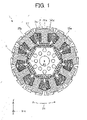
- FIG. 1 is a cross-sectional view schematically illustrating an internal structure of the motor 1 including the stator 2 according to a first embodiment of the present invention.
- the motor 1 includes the stator 2 and the rotor 3.
- the motor 1 is, for example, an interior permanent magnet motor.
- the motor 1 is a motor disposed in a compressor to be used with a refrigerant containing a substance having a property of causing disproportionation.
- the refrigerant described above only needs to contain 1wt% or more of a substance having a property of causing disproportionation.
- the refrigerant may be a refrigerant composed only of a substance having a property of causing disproportionation. That is, the proportion of the substance having a property of causing disproportionation in the refrigerant described above only needs to be 1wt% to 100wt%.
- the substance having a property of causing disproportionation is, for example, 1,1,2-trifluoroethylene or 1,2-difluoroethylene.
- the refrigerant described above only needs to contain 1wt% or more of 1,1,2-trifluoroethylene.
- the refrigerant may be a refrigerant composed only of 1,1,2-trifluoroethylene. That is, the refrigerant only needs to contain 1wt% to 100wt% of 1,1,2-trifluoroethylene.
- the refrigerant described above only needs to contain 1wt% or more of 1,2-difluoroethylene.
- the refrigerant may be a refrigerant composed only of 1,2-difluoroethylene. That is, the refrigerant only needs to contain 1wt% to 100wt% of 1,2-difluoroethylene.
- the refrigerant described above may be a mixture of 1,1,2-trifluoroethylene and difluoromethane (also referred to as R32).
- R32 may be replaced by another substance.
- a mixture of 1,1,2-trifluoroethylene and another ethylene-based fluorocarbon may be used as a refrigerant.
- Examples of another ethylene-based fluorocarbon include fluoroethylene (also referred to as HFO-1141), 1,1-difluoroethylene (also referred to as HFO-1132a), trans-1,2-difluoroethylene (also referred to as “HFO-1132(E)”), and cis-1,2-difluoroethylene (also referred to as "HFO-1132(Z)").
- R32 may be replaced by any one of 2,3,3,3-tetrafluoropropene (also referred to as R1234yf), trans-1,3,3,3-tetrafluoropropene (also referred to as “R1234ze(E)”), cis-1,3,3,3-tetrafluoropropene (also referred to as “R1234ze(Z)”), 1,1,1,2-tetrafluoroethane (also referred to as R134a), or 1,1,1,2,2-pentafluoroethane (also referred to as R125).
- R32 may be replaced by a mixture of at least two of R32, R1234yf, R1234ze(E), R1234ze(Z), R134a, and R125.
- the stator 2 includes an annular stator core 2a and coils 27 wound around the stator core 2a.
- the stator 2 is formed in an annular shape in a circumferential direction about the axis A1 (i.e., the rotation center of the rotor 3).
- the stator 2 is disposed outside the rotor 3.
- the rotor 3 is rotatably provided inside the stator 2.
- An air gap of 0.3 mm to 1 mm is provided between the inner surface of the stator 2 and the outer surface of the rotor 3.
- the stator 2 includes a plurality of divided iron cores 25a.
- the plurality of divided iron cores 25a are arranged in an annular shape in the circumferential direction about the axis A1 to thereby form the stator 2.
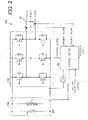
- FIG. 2 is a block diagram illustrating a configuration of the driving device 101.
- the motor 1 may include the driving device 101 illustrated in FIG. 2 .
- the driving device 101 includes a converter 102 that rectifies an output of a power supply, an inverter 103 that supplies electric power to the stator 2 (specifically, the coils 27) of the motor 1, and a control device 50.
- the coils 27 are three-phase coils having a U phase, a V phase, and a W phase.
- the converter 102 is supplied with electric power from a power supply that is an alternating current power supply.
- the converter 102 applies a voltage to the inverter 103.
- a voltage applied from the converter 102 to the inverter 103 will also be referred to as a "converter voltage.”
- a bus voltage of the converter 102 is supplied to the control device 50.
- the inverter 103 operates by a pulse width modulation control method (also referred to as a PWM control method).
- An inverter voltage for driving the motor 1, that is, a voltage applied to the coils 27 of the motor 1, is generated by a PWM control method.
- the coils 27 of the motor 1 are, for example, three-phase coils.
- the inverter 103 includes at least one inverter switch corresponding to each phase, and each inverter switch includes a pair of switching devices (two switching devices in this embodiment).
- a waveform of an inverter voltage is generated by controlling proportions of on and off times of the inverter switch corresponding to each phase. In this manner, a desired output waveform from the inverter 103 can be obtained.
- the inverter 103 when the inverter is on, a voltage is supplied from the inverter 103 to the coils 27, and an inverter voltage increases.
- the inverter switch is off, a voltage supply from the inverter 103 to the coils 27 is shut off, and the inverter voltage decreases. A difference between the inverter voltage and an induced voltage is supplied to the coils 27, a motor current is generated, and a rotary force of the motor 1 occurs.
- the proportions of on and off times of the inverter switch is controlled to match with a target motor current value and consequently a desired output waveform from the inverter 103 can be thereby obtained.
- An on/off timing of each inverter switch is determined based on a carrier wave.
- the carrier wave is constituted by a triangular wave having a constant amplitude.
- a pulse width modulation cycle in the PWM control method is determined by a carrier frequency that is a frequency of a carrier wave.
- the control device 50 stores a predetermined pattern of a carrier wave or a predetermined carrier frequency. The control device 50 controls the carrier frequency, and controls on and off of each inverter switch. In this manner, the control device 50 controls an output from the inverter 103 to be supplied to the coils 27.
- a carrier frequency that is a frequency of a carrier wave will also be referred to as a "carrier frequency of the inverter 103." That is, the carrier frequency of the inverter 103 is a control frequency of a voltage to be applied to the coils 27, the control device 50 controls the carrier frequency of the inverter 103.
- the inverter 103 includes three inverter switches (i.e., six switching devices), and control on one of the three inverter switches, that is, one inverter switch corresponding the U phase, the V phase, or the W phase, will be described.
- the control on one inverter switch is also applicable to control on the other two inverter switches.
- the control device 50 compares a voltage value of a carrier wave with an inverter output voltage instruction value.
- the inverter output voltage instruction value is calculated based on a target motor current value in the control device 50, for example.
- the inverter output voltage instruction value is set based on, for example, a driving instruction signal input to the control device 50 from a remote controller of a refrigeration air conditioning apparatus such as an air conditioner.
- the control device 50 turns a PWM control signal so that an inverter switch is turned on. If a voltage value of a carrier wave is greater than or equal to the inverter output voltage instruction value, the control device 50 turns the PWM control signal off so that the inverter switch is turned off. Accordingly, the inverter voltage approaches a target value.
- control device 50 generates a PWM control signal based on a difference between the inverter output voltage instruction value and a voltage value of a carrier wave.
- the control device 50 outputs a control signal such as an inverter driving signal based on a PWM control signal to the inverter 103, and performs on/off control of the inverter switch.
- the inverter driving signal may be the same as the PWM control signal, or may be different from the PWM control signal.
- an inverter voltage is output from the inverter 103.
- the inverter voltage is supplied to the coils 27, a motor current (specifically, a U-phase current, a V-phase current, and a W-phase current) is generated in the motor 1. Accordingly, an inverter voltage is converted to a rotary force of the motor 1 (specifically, the rotor 3).
- the motor current is measured by a measuring instrument such as a current sensor, and a measurement result (e.g., a signal indicating a current value) is transmitted to the control device 50.
- the control device 50 is composed of, for example, a processor and a memory.
- the control device 50 is a microcomputer.
- the control device 50 may be composed of a processing circuit as dedicated hardware such as a single circuit or a composite circuit.
- FIG. 3 is a perspective view schematically illustrating a structure of the divided iron core 25a.
- the stator 2 is composed of the plurality of divided iron cores 25a.
- Each of the divided iron cores 25a includes an iron core part 21 as a divided iron core, first insulators 24a, a second insulator 24b, and a coil 27.
- the example illustrated in FIG. 3 does not show the coil 27.
- the first insulators 24a are combined with the stator core 2a (specifically, the iron core part 21). In this embodiment, the first insulators 24a are provided at both end of the stator core 2a in the axial direction. The first insulator 24a may be provided at one end of the stator core 2a in the axial direction. In this embodiment, the first insulator 24a is an insulating resin.
- the second insulator 24b is, for example, a thin polyethylene terephthalate (PET) film.
- PET polyethylene terephthalate
- the PET film has a thickness of, for example, 0.15 mm.
- the second insulator 24b covers a side surface of a tooth part (a tooth part 22a described later) of the stator core 2a.
- FIG. 4 is a plan view schematically illustrating a structure of the stator core 2a.
- the stator core 2a includes at least one yoke part 21a and at least two tooth parts 22a.
- the stator core 2a is composed of a plurality of iron core parts 21.
- each of the iron core parts 21 includes the yoke part 21a and the tooth parts 22a.
- the stator core 2a is composed of nine iron core parts 21.
- the stator core 2a may not be divided into the plurality of iron core parts 21.
- the stator core 2a may be composed of the plurality of iron core parts 21 integrated as one member.
- the stator core 2a may be formed by laminating a plurality of annular materials (e.g., electromagnetic steel sheets).
- a region surrounded by two yoke parts 21a and two tooth parts 22a is a slot part 26.
- a plurality of slot parts 26 are arranged at regular intervals in the circumferential direction. In the example illustrated in FIG. 4 , the stator core 2a has nine slot parts 26.
- the stator core 2a includes the plurality of tooth parts 22a, and each of the tooth parts 22a is adjacent to another tooth part 22a across the slot part 26. Accordingly, the plurality of tooth parts 22a and the plurality of slot parts 26 are alternately arranged in the circumferential direction.
- the pitch of the plurality of tooth parts 22a arranged in the circumferential direction i.e., the width of the slot parts 26 in the circumferential direction
- the pitch of the plurality of tooth parts 22a arranged in the circumferential direction is uniform. That is, the plurality of tooth parts 22a are radially positioned.
- the stator 2 includes N divided iron cores 25a (where N is a natural number of two or more).
- the stator 2 includes N tooth parts 22a.
- the stator 2 includes nine divided iron cores 25a. Accordingly, in the example illustrated in FIG. 1 , the stator 2 includes nine tooth parts 22a.
- FIG. 5 is a cross-sectional view schematically illustrating a structure of the divided iron core 25a.
- Each of the divided iron cores 25a includes the yoke part 21a, the tooth part 22a located at the inner side of the yoke part 21a in the radial direction, the coil 27, the first insulator 24a insulating the stator core 2a, and the second insulator 24b insulating the stator core 2a.
- the tooth part 22a is integrated with the yoke part 21a as one member, but a tooth part 22a formed as a separate member from the yoke part 21a may be attached to the yoke part 21a.
- the coil 27 is wound around the stator core 2a with the first insulator 24a and the second insulator 24b interposed therebetween. Specifically, the coil 27 is wound around the tooth part 22a. When a current flows through the coil 27, a rotating magnetic field is generated from the coil 27.
- the coil 27 is, for example, a magnet wire.
- the stator 2 has three phases, and connection of the coil 27 is, for example, Y connection (also referred to as star connection) or delta connection.
- the number of turns and the wire diameter of each coil 27 are determined depending on the rotation speed of the motor 1, torque, voltage specifications, and the cross-sectional area of the slot parts 26, for example.
- the wire diameter of the coil 27 is, for example, 1.0 mm.
- the coil 27 is wound around each tooth part 22a of the stator core 2a in, for example, 80 turns. The wire diameter and the number of turns of the coil 27 are not limited to these examples.
- the winding method of the coils 27 is, for example, concentrated winding.
- the coils 27 can be wound around the iron core parts 21 in a state before the iron core parts 21 are arranged in the annular shape (e.g., a state where the iron core parts 21 are arranged linearly).
- the iron core parts 21 (i.e., the divided iron cores 25a) around which the coils 27 are wound are folded in an annular shape and fixed by, for example, welding.
- the coils 27 may be attached to the tooth parts 22a of the stator core 2a by distributed winding, instead of concentrated winding.
- FIG. 6 is a plan view schematically illustrating a structure of the iron core part 21.
- FIG. 7 is a perspective view schematically illustrating a structure of the iron core part 21.
- the yoke part 21a extends in the circumferential direction, and the tooth part 22a extends inward (in the -y direction in FIG. 6 ) in the radial direction of the stator core 2a. In other words, the tooth part 22a projects from the yoke part 21a toward the axis A1.
- each tooth part 22a includes a body 221a, a tooth tip 222a, and a tooth end surface 223a.
- the tooth tip 222a is disposed at the tip of the tooth part 22a (specifically, an end of the body 221a) in the radial direction.
- the body 221a has a uniform width in the radial direction.
- the tooth tip 222a extends in the circumferential direction, and is formed to expand in the circumferential direction.
- the tooth end surface 223a faces the rotor 3 in the motor 1. Specifically, the tooth end surface 223a is a surface of the tooth tip 222a facing the rotor 3 in the motor 1.
- the iron core part 21 (e.g., the yoke part 21a) has a fixing hole 24c for fixing the first insulator 24a.
- the iron core part 21 is constituted by at least one sheet 28 (also referred to as a plate).
- the iron core part 21 is formed by laminating a plurality of sheets 28 in the axial direction (i.e., in the z-axis direction).
- the sheets 28 are formed in a predetermined shape by press work (specifically, punching).
- the sheets 28 are, for example, electromagnetic steel sheets.
- each of the sheets 28 has a thickness of, for example, 0.01 mm through 0.7 mm. In this embodiment, the thickness of each sheet 28 is 0.35 mm.
- Each of the sheets 28 is fixed to its adjacent sheet 28 by caulked parts 24d.
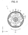
- FIG. 8 is a cross-sectional view schematically illustrating the structure of the rotor 3.
- the rotor 3 includes a rotor core 31, a shaft 32, at least one permanent magnet 33, at least one magnet insertion hole 34, at least one flux barrier 35, at least one air opening 36, and at least one slit 38.
- the rotor 3 is rotatable about the axis A1.
- the rotor 3 is rotatably disposed inside the stator 2.
- the axis A1 is the rotation center of the rotor 3, and is the axis of the shaft 32.
- the rotor 3 is an interior permanent magnet rotor.
- the rotor core 31 has a plurality of magnet insertion holes 34 arranged in the circumferential direction of the rotor 3.
- the magnet insertion holes 34 are space in which the permanent magnets 33 are arranged.
- One permanent magnet 33 is disposed in each of the magnet insertion holes 34.
- a plurality of permanent magnets 33 may be disposed in each of the magnet insertion holes 34.
- the permanent magnets 33 disposed in the magnet insertion holes 34 are magnetized in the radial direction of the rotor 3 (i.e., the direction perpendicular to the axis A1).
- the number of magnet insertion holes 34 corresponds to the number of magnetic poles of the rotor 3.
- the positional relationships of the magnetic poles are the same.
- the number of magnetic poles of the rotor 3 is six.
- the number of magnetic poles of the rotor 3 only needs to be two or more.
- Nd-Fe-B permanent magnets Rare earth magnets containing neodymium (Nd), iron (Fe), and boron (B) (hereinafter referred to as "Nd-Fe-B permanent magnets"), for example, are applied to the permanent magnets 33.
- a coercive force of the Nd-Fe-B permanent magnets has a property of decreasing depending on the temperature.
- a coercive force of the magnets decreases by about -0.5 to -0.6%/ ⁇ K depending on the temperature, and thus, a dysprosium (Dy) element needs to be added in order to increase the coercive force.
- the coercive force increases substantially in proportion to the content of the Dy element.
- the upper limit of an ambient temperature of a motor is about 150°C, and the motor is used in a temperature rise range of about 130°C with respect to 20°C.
- the coercive force decreases by 65% at a temperature coefficient of -0.5%/ ⁇ K.
- a coercive force of about 1100 to 1500 A/m is needed.
- a coercive force at room temperature needs to be designed at about 1800 to 2300 A/m.
- the coercive force at room temperature is about 1800 A/m.
- about 2wt% of the Dy element needs to be added.
- a coercive force property is enhanced, but a remaining magnetic flux density property decreases.
- a magnet torque of the motor decreases and a supply current increases. Accordingly, a copper loss increases.
- the rotor core 31 is formed by laminating a plurality of electromagnetic steel sheets.
- Each of the electromagnetic steel sheets of the rotor core 31 has a thickness of, for example, 0.1 mm to 0.7 mm. In this embodiment, the thickness of each electromagnetic steel sheet of the rotor core 31 is 0.35 mm.
- Each of the electromagnetic steel sheets of the rotor core 31 is fixed to its adjacent electromagnetic steel sheet by caulking.
- At least one slit 38 is formed outside each magnet insertion hole 34 in the radial direction of the rotor 3.
- a plurality of slits 38 are formed outside each magnet insertion hole 34 in the radial direction of the rotor 3.
- Each of the slits 38 is elongated in the radial direction.
- the shaft 32 is coupled to the rotor core 31.
- the shaft 32 is fixed to a shaft hole 37 formed in the rotor core 31 by a fixing method such as shrink fitting or press fitting. In this manner, rotational energy generated by rotation of the rotor core 31 is transferred to the shaft 32.
- the flux barrier 35 is formed at a position adjacent to the magnet insertion hole 34 in the circumferential direction of the rotor 3. In other words, each flux barrier 35 is adjacent to an end portion of a corresponding one of the magnet insertion holes 34 in the longitudinal direction of the magnet insertion hole 34.
- the flux barrier 35 reduces leakage flux.
- the width of a thin portion between the flux barrier 35 and the outer peripheral surface of the rotor core 31 is preferably small.
- the width of the thin portion between the flux barrier 35 and the outer peripheral surface of the rotor core 31 is, for example, 0.35 mm.
- the air opening 36 is a through hole. For example, in a case where the motor 1 is used in a compressor, a refrigerant is allowed to pass through the air opening 36.
- a structure of the tooth part 22a will be specifically described.
- FIG. 9 is a diagram illustrating a structure of the tooth part 22a.
- the stator 2 satisfies 0.75 ⁇ ( ⁇ 1 ⁇ N)/360 ⁇ 0.97, where ⁇ 1 (degrees) is an angle formed by two lines L1 passing through both ends PI of the tooth end surface 223a and the rotation center of the rotor 3.
- N 9. It should be noted that N only needs to be a natural number of two or more.
- a proportion ⁇ [%] of the tooth end surface 223a in the circumference of a circle passing through the tooth end surface 223a is 75% or more and 97% or less.
- This proportion ⁇ will be hereinafter referred to as an aperture angle proportion ⁇ .
- the circle passing through the tooth end surface 223a is, for example, a circle indicated by the broken line R1 in FIG. 4 .
- FIG. 10 is a cross-sectional view schematically illustrating another example of the motor 1.
- the rotor 3 In the axial direction of the rotor 3, the rotor 3 is longer than the stator 2. In this case, the rotor 3 only needs to be longer than the stator core 2a.
- FIG. 11 is a cross-sectional view schematically illustrating still another example of the motor 1.
- FIG. 12 is a plan view schematically illustrating an example of the metal member 39.
- the rotor 3 includes at least one metal member 39.
- the metal member 39 is fixed to an end of the rotor core 31 in the axial direction of the rotor 3.
- the rotor 3 includes two metal members 39, and the metal members 39 are fixed to both ends of the rotor core 31.
- Each of the metal members 39 is preferably a single structure. Accordingly, costs for the metal members 39 can be reduced.
- a surface area of each metal member 39 is larger than a surface area of the rotor core 31 (specifically, the surface of the rotor core 39 facing the metal member 39).
- FIG. 13 is a diagram illustrating another example of the rotor 3.
- the rotor 3 may include a rotor core 31a illustrated in FIG. 13 , instead of the rotor core 31.
- the rotor core 31a illustrated in FIG. 13 has a plurality of different radiuses in the xy plane. Specifically, the radius of the rotor core 31a is at maximum in magnetic pole center parts of the rotor 3 and at minimum in inter-pole parts of the rotor 3. In the example illustrated in FIG. 13 , the outer diameter of the rotor core 31a is at maximum in magnetic pole center parts of the rotor 3 and at minimum in inter-pole parts of the rotor 3. In the xy plane illustrated in FIG.
- each of the magnetic pole center parts of the rotor 3 is located on a line passing through the center of the corresponding permanent magnet 33 and the axis A1.
- each of the inter-pole parts of the rotor 3 is located on a line passing through a point between adjacent permanent magnets 33 and the axis A1.
- FIG. 14 is a graph showing a relationship between a rotation angle of the rotor and an internal pressure of a cylinder.
- the solid line B1 corresponds to a motor having a large torque ripple
- the broken line B2 corresponds to a motor having a small torque ripple.
- a compressor when compression of a refrigerant starts, the internal pressure of a cylinder increases. When the internal pressure reaches a target discharge pressure satisfying a required capacity, the refrigerant pushes away a valve, and the valve is opened. Accordingly, the cylinder communicates with a discharging muffler, and the refrigerant is discharged from a discharge pipe under a target discharge pressure.
- a refrigerant containing a substance having a property of causing disproportionation such as 1,1,2-trifluoroethylene or 1,2-difluoroethylene
- a refrigerant containing a substance having a property of causing disproportionation rapidly causes volume expansion due to a chain of disproportionation reactions, and a failure is likely to occur in the cylinder in the compressor.
- occurrence of a pressure overshoot is preferably suppressed as much as possible.
- a torque ripple occurs during driving of a motor
- the rotation speed of the motor fluctuates during driving of the motor.
- an instantaneous rotation speed increases, an instantaneous internal pressure of a cylinder increases, and a failure is more likely to occur in the cylinder.
- FIG. 15 is a graph showing a relationship between an aperture angle proportion ⁇ [%] and a torque ripple ratio [%] in a case where a motor is driven with a torque less than or equal to a rated torque.
- FIG. 16 is a diagram illustrating a magnetic flux density in the stator core 2a in the case where a motor is driven with a torque less than or equal to the rated torque.
- FIG. 17 is a diagram illustrating a magnetic flux density in the stator core 2a in a case where a motor is driven with a torque larger than the rated torque.
- the torque ripple ratio is a ratio of a difference between a maximum torque and a minimum torque to a time average torque.
- fluctuation of the rotation speed of the motor during driving of the motor decreases, and a pressure overshoot is less likely to occur.
- FIG. 16 when a torque load is small, influence of magnetic saturation in each tooth part is small.
- FIG. 17 when a torque load is large, magnetic saturation in each tooth part increases. For example, when a torque load is large in the motor in the compressor, the internal pressure of the cylinder increases. Accordingly, a failure in the compressor due to disproportionation of a refrigerant is likely to occur.
- the angle ⁇ 1 affects a magnetic attraction force generated between the stator and the rotor. Consequently, the angle ⁇ 1 affects the torque ripple ratio.
- FIG. 18 is a graph showing a relationship between an aperture angle proportion ⁇ [%] and a torque ripple ratio [%] in a case where the motor 1 is driven with a torque larger than the rated torque.
- the torque ripple ratio can be effectively reduced. That is, in the range of 0.75 ⁇ ( ⁇ 1 ⁇ N)/360, the torque ripple ratio can be effectively reduced.
- the torque ripple ratio can be more effectively reduced. That is, in the range of 0.84 ⁇ ( ⁇ 1 ⁇ N)/360, the torque ripple ratio can be more effectively reduced.
- the aperture angle proportion ⁇ is preferably 75% or more and 97% or less. That is, the stator 2 preferably satisfies 0.75 ⁇ ( ⁇ 1 ⁇ N)/360 ⁇ 0.97. In this manner, the torque ripple ratio can be effectively reduced. As a result, a failure in the compressor is less likely to occur.
- the aperture angle proportion ⁇ is more preferably 84% or more and 97% or less. That is, the stator 2 more preferably satisfies 0.84 ⁇ ( ⁇ 1 ⁇ N)/360 ⁇ 0.97. In this manner, the torque ripple ratio can be more effectively reduced. As a result, a failure in the compressor can be much less likely to occur.
- the aperture angle proportion ⁇ is more preferably 87.5% or more and 92.5% or less. That is, the stator 2 more preferably satisfies 0.875 ⁇ ( ⁇ 1 ⁇ N)/360 ⁇ 0.925. In this manner, the torque ripple ratio can be more effectively reduced. As a result, a failure in the compressor can be much less likely to occur.
- the aperture angle proportion ⁇ may be 87.5% or more and 97% or less. That is, when the stator 2 satisfies 0.875 ⁇ ( ⁇ 1 ⁇ N)/360 ⁇ 0.97, the torque ripple ratio can be effectively reduced. As a result, a failure in the compressor is less likely to occur.
- the aperture angle proportion ⁇ may be 87.5% or more and 92.5% or less. That is, when stator 2 satisfies 0.875 ⁇ ( ⁇ 1 ⁇ N)/360 ⁇ 0.925, the torque ripple ratio can be effectively reduced. As a result, a failure in the compressor is less likely to occur.
- the aperture angle proportion ⁇ may be 84% or more and 92.5% or less. That is, when the stator 2 satisfies 0.84 ⁇ ( ⁇ 1 ⁇ N)/360 ⁇ 0.925, the torque ripple ratio can be effectively reduced. As a result, a failure in the compressor is less likely to occur.
- the motor 1 includes an inverter that operates by a PWM control method
- waveform of an inverter can be finely adjusted. Accordingly, torque waveform of the motor 1 due to an inverter voltage can be controlled, and the torque ripple ratio can be reduced.
- the rotor 3 In a case where the rotor 3 is longer than the stator 2 in the axial direction of the rotor 3, the moment of inertia of the rotor 3 can be increased. Accordingly, occurrence of a pressure overshoot can be suppressed.
- the stator 2 In a case where the stator 2 is shorter than the rotor 3 in the axial direction of the rotor 3, the size of the motor 1 can be reduced. Thus, the size of the compressor including the motor 1 can also be reduced.
- the moment of inertia of the rotor 3 can be increased. Accordingly, occurrence of a pressure overshoot can be suppressed.
- a surface area of the metal member 39 is preferably larger than a surface area of the rotor core 31 (specifically, the surface of the rotor core 31 facing the metal member 39). Accordingly, the moment of inertia of the rotor 3 can be further increased. As a result, occurrence of a pressure overshoot can be effectively reduced.
- the magnetic flux density at the outer peripheral surface of the rotor 3 is at maximum in magnetic pole center parts and at minimum in inter-pole parts at the outer peripheral surface. That is, as the distance from the magnetic pole center parts toward the inter-pole part decreases, the magnetic flux density at the outer peripheral surface of the rotor 3 decreases. Accordingly, the waveform of an induced voltage in the motor 1 approaches a sine wave, and the torque ripple ratio can be reduced. As a result, occurrence of a pressure overshoot can be suppressed.
- a compressor 6 according to a second embodiment of the present invention will be described.
- FIG. 19 is a cross-sectional view schematically illustrating a structure of the compressor 6 according to the
- the compressor 6 includes a motor 1 serving as an electric element, a closed container 61 serving as a housing, and a compression mechanism 62 serving as a compression element (also referred to as a compression device).
- the compressor 6 is used with the refrigerant described in the first embodiment, that is, a refrigerant containing a substance having a property of causing disproportionation. This refrigerant may be previously provided in the compressor 6.
- the compressor 6 is a rotary compressor.
- the compressor 6 is not limited to a rotary compressor.
- the motor 1 in the compressor 6 is the motor 1 described in the first embodiment.
- the motor 1 drives the compression mechanism 62.
- the motor 1 is an interior permanent magnet motor, but the present invention is not limited to this motor.
- the closed container 61 covers the motor 1 and the compression mechanism 62. Refrigerating machine oil for lubricating a sliding part of the compression mechanism 62 is stored in a bottom portion of the closed container 61.
- the compressor 6 also includes a glass terminal 63 fixed to the closed container 61, an accumulator 64, a suction pipe 65 for sucking a refrigerant, and a discharge pipe 66 for discharging a refrigerant.
- the suction pipe 65 and the discharge pipe 66 are fixed to the closed container 61.
- the compression mechanism 62 is disposed inside the closed container 61. In this embodiment, the compression mechanism 62 is disposed in a lower portion of the closed container 61.
- the compression mechanism 62 includes a cylinder 62a, a piston 62b, an upper frame 62c (first frame), a lower frame 62d (second frame), and a plurality of mufflers 62e individually attached to the upper frame 62c and the lower frame 62d.
- the compression mechanism 62 also includes a vane that divides the inside of the cylinder 62a into a suction side and a compression side.
- the compression mechanism 62 is driven by the motor 1.
- the compression mechanism 62 compresses a refrigerant.
- the motor 1 is disposed in an upper portion of the closed container 61. Specifically, the motor 1 is located between the discharge pipe 66 and the compression mechanism 62. That is, the motor 1 is disposed above the compression mechanism 62.
- the stator 2 of the motor 1 is fixed in the closed container 61 by a fixing method such as press fitting or shrink fitting.
- the stator 2 may be attached directly to the closed container 61 by welding instead of press fitting or shrink fitting.
- the coils (e.g., the coils 27 illustrated in FIG. 1 ) of the stator 2 of the motor 1 are supplied with electric power through the glass terminal 63.
- a rotor (specifically, a shaft 32 of a rotor 3) of the motor 1 is rotatably held by the upper frame 62c and the lower frame 62d with interposition of bearing parts individually included in the upper frame 62c and the lower frame 62d.
- the shaft 32 is inserted in the piston 62b.
- the shaft 32 is rotatably inserted in the upper frame 62c and the lower frame 62d.
- the upper frame 62c is provided with a valve for preventing a backflow of a refrigerant. Specifically, this valve is located between the upper frame 62c and the muffler 62e.
- the upper frame 62c and the lower frame 62d close an end face of the cylinder 62a.
- the accumulator 64 supplies a refrigerant to the cylinder 62a through the suction pipe 65.
- the refrigerant supplied from the accumulator 64 enters the cylinder 62a through the suction pipe 65 fixed to the closed container 61.
- the piston 62b fitted in the shaft 32 rotates in the cylinder 62a. Accordingly, the refrigerant is compressed in the cylinder 62a.
- the refrigerant flows through the mufflers 62e and moves upward in the closed container 61.
- the valve provided on the upper frame 62c is opened and thus the compressed refrigerant is discharged from the discharge pipe 66.
- the compressed refrigerant is supplied toward a highpressure side of a refrigeration cycle through the discharge pipe 66.
- the valve is closed and thus a flow of the refrigerant is shut off.
- the compressor 6 according to the second embodiment includes the motor 1 described in the first embodiment, a failure in the compressor 6 is less likely to occur.
- a refrigeration air conditioning apparatus 7 serving as an air conditioner and including the compressor 6 according to the second embodiment of the present invention will be described.
- FIG. 20 is a diagram schematically illustrating a configuration of the refrigerating air conditioning device 7 according to a third embodiment.
- the refrigeration air conditioning apparatus 7 is capable of performing cooling and heating operations, for example.
- a refrigerant circuit diagram illustrated in FIG. 20 is an example of a refrigerant circuit diagram of an air conditioner capable of performing a cooling operation.
- the refrigeration air conditioning apparatus 7 includes an outdoor unit 71, an indoor unit 72, and a refrigerant pipe 73 connecting the outdoor unit 71 and the indoor unit 72 to each other.
- the outdoor unit 71 includes a compressor 6, a condenser 74 serving as a heat exchanger, a throttling device 75, and an outdoor air blower 76 (first air blower).
- the condenser 74 condenses a refrigerant compressed by the compressor 6.
- the throttling device 75 decompresses the refrigerant condensed by the condenser 74 to thereby adjust a flow rate of the refrigerant.
- the throttling device 75 will also be referred to as a decompression device.
- the indoor unit 72 includes an evaporator 77 serving as a heat exchanger, and an indoor air blower 78 (second air blower).
- the evaporator 77 evaporates the refrigerant decompressed by the throttling device 75 to thereby cool indoor air.
- a refrigerant is compressed by the compressor 6 and the compressed refrigerant flows into the condenser 74.
- the condenser 74 condenses the refrigerant, and the condensed refrigerant flows into the throttling device 75.
- the throttling device 75 decompresses the refrigerant, and the decompressed refrigerant flows into the evaporator 77.
- the refrigerant evaporates, and the refrigerant (specifically a refrigerant gas) flows into the compressor 6 of the outdoor unit 71 again.
- the refrigerating air conditioning device 7 according to the third embodiment has the advantages described in the first and second embodiments.
- the refrigeration air conditioning apparatus 7 includes the compressor 6, a failure in the refrigeration air conditioning apparatus 7 is less likely to occur.
Landscapes
- Engineering & Computer Science (AREA)
- Power Engineering (AREA)
- Iron Core Of Rotating Electric Machines (AREA)
- Applications Or Details Of Rotary Compressors (AREA)
- Connection Of Motors, Electrical Generators, Mechanical Devices, And The Like (AREA)
- Compressor (AREA)
Abstract
Description
- The present invention relates to a stator of a motor.
- As a refrigerant of a compressor, a refrigerant including 1,1,2-trifluoroethylene is generally used (see, for example, Patent Reference 1).
- Patent Reference 1: International Patent Publication No.
2015/136977 - In conventional techniques, however, depending on structures of a motor in a compressor, a refrigerant might expand to cause a failure in a cylinder in the compressor. As a result, a failure might occur in the compressor.
- It is therefore an object of the present invention to solve the problem described above and reduce occurrence of a failure in a compressor.
- A stator according to an aspect of the present invention is a stator to be disposed outside a rotor of a motor disposed in a compressor used with a refrigerant containing a substance having a property of causing disproportionation, and the stator includes: a yoke part; and N tooth parts, wherein each of the N tooth parts includes a tooth end surface to face the rotor, and the stator satisfies 0.75 ≤ (θ1 × N)/360 ≤ 0.97, where θ1 (degrees) is an angle formed by two lines passing through both ends of the tooth end surface and a rotation center of the rotor in a plane perpendicular to an axial direction of the rotor.
- A motor according to another aspect of the present invention includes: the stator; and the rotor disposed inside the stator.
- A compressor according to another aspect of the present invention includes: a closed container; a compression device disposed in the closed container; and the motor to drive the compression device.
- An air conditioner according to another aspect of the present invention includes: the compressor; and a heat exchanger.
- According to the present invention, a failure in a compressor is less likely to occur.
-
-
FIG. 1 is a cross-sectional view schematically illustrating an internal structure of a motor including a stator according to a first embodiment of the present invention. -
FIG. 2 is a block diagram illustrating a configuration of a driving device. -
FIG. 3 is a perspective view schematically illustrating a structure of a divided iron core. -
FIG. 4 is a plan view schematically illustrating a structure of a stator core. -
FIG. 5 is a cross-sectional view schematically illustrating a structure of the divided iron core. -
FIG. 6 is a plan view schematically illustrating a structure of an iron core part. -
FIG. 7 is a perspective view schematically illustrating a structure of the iron core part. -
FIG. 8 is a cross-sectional view schematically illustrating a structure of a rotor. -
FIG. 9 is a diagram illustrating a structure of a tooth part. -
FIG. 10 is a cross-sectional view schematically illustrating another example of the motor. -
FIG. 11 is a cross-sectional view schematically illustrating still another example of the motor. -
FIG. 12 is a plan view schematically illustrating an example of a metal member. -
FIG. 13 is a diagram illustrating another example of the rotor. -
FIG. 14 is a graph showing a relationship between a rotation angle of the rotor and an internal pressure of a cylinder. -
FIG. 15 is a graph showing a relationship between an aperture angle proportion [%] and a torque ripple ratio [%] in a case where the motor is driven with a torque less than or equal to a rated torque. -
FIG. 16 is a diagram illustrating a magnetic flux density in a stator core in the case where the motor is driven with a torque less than or equal to the rated torque. -
FIG. 17 is a diagram illustrating a magnetic flux density in a stator core in a case where the motor is driven with a torque larger than the rated torque. -
FIG. 18 is a graph showing a relationship between an aperture angle proportion [%] and a torque ripple ratio [%] in the case where a motor is driven with a torque larger than the rated torque. -
FIG. 19 is a cross-sectional view schematically illustrating a structure of a compressor according to a second embodiment of the present invention. -
FIG. 20 is a diagram schematically illustrating a configuration of a refrigeration air conditioning apparatus according to a third embodiment of the present invention. - In an xyz orthogonal coordinate system shown in each drawing, a z-axis direction (z axis) represents a direction parallel to an axis A1 of a
motor 1, an x-axis direction (x axis) represents a direction perpendicular to the z-axis direction (z axis), and a y-axis direction (y axis) represents a direction perpendicular to both the z-axis direction and the x-axis direction. The axis A1 is a rotation center of arotor 3. The axis A1 also represents a center of astator 2. The direction parallel to the axis A1 is also referred to as an "axial direction of themotor 1," "axial direction of therotor 3," or simply as an "axial direction." A radial direction refers to a radial direction of therotor 3 or thestator 2, and is a direction perpendicular to the axis A1. An xy plane is a plane perpendicular to the axial direction. An arrow D1 represents a circumferential direction about the axis A1. A circumferential direction of therotor 3 or thestator 2 will also be referred to as a "circumferential direction." -
FIG. 1 is a cross-sectional view schematically illustrating an internal structure of themotor 1 including thestator 2 according to a first embodiment of the present invention. - The
motor 1 includes thestator 2 and therotor 3. Themotor 1 is, for example, an interior permanent magnet motor. - The
motor 1 is a motor disposed in a compressor to be used with a refrigerant containing a substance having a property of causing disproportionation. - For example, the refrigerant described above only needs to contain 1wt% or more of a substance having a property of causing disproportionation. The refrigerant may be a refrigerant composed only of a substance having a property of causing disproportionation. That is, the proportion of the substance having a property of causing disproportionation in the refrigerant described above only needs to be 1wt% to 100wt%.
- The substance having a property of causing disproportionation is, for example, 1,1,2-trifluoroethylene or 1,2-difluoroethylene.
- For example, the refrigerant described above only needs to contain 1wt% or more of 1,1,2-trifluoroethylene. The refrigerant may be a refrigerant composed only of 1,1,2-trifluoroethylene. That is, the refrigerant only needs to contain 1wt% to 100wt% of 1,1,2-trifluoroethylene.
- For example, the refrigerant described above only needs to contain 1wt% or more of 1,2-difluoroethylene. The refrigerant may be a refrigerant composed only of 1,2-difluoroethylene. That is, the refrigerant only needs to contain 1wt% to 100wt% of 1,2-difluoroethylene.
- The refrigerant described above may be a mixture of 1,1,2-trifluoroethylene and difluoromethane (also referred to as R32). For example, a mixture containing 40wt% of 1,1,2-trifluoroethylene and 60wt% of R32 may be used as a refrigerant. In this mixture, R32 may be replaced by another substance. For example, a mixture of 1,1,2-trifluoroethylene and another ethylene-based fluorocarbon may be used as a refrigerant. Examples of another ethylene-based fluorocarbon include fluoroethylene (also referred to as HFO-1141), 1,1-difluoroethylene (also referred to as HFO-1132a), trans-1,2-difluoroethylene (also referred to as "HFO-1132(E)"), and cis-1,2-difluoroethylene (also referred to as "HFO-1132(Z)").
- R32 may be replaced by any one of 2,3,3,3-tetrafluoropropene (also referred to as R1234yf), trans-1,3,3,3-tetrafluoropropene (also referred to as "R1234ze(E)"), cis-1,3,3,3-tetrafluoropropene (also referred to as "R1234ze(Z)"), 1,1,1,2-tetrafluoroethane (also referred to as R134a), or 1,1,1,2,2-pentafluoroethane (also referred to as R125). R32 may be replaced by a mixture of at least two of R32, R1234yf, R1234ze(E), R1234ze(Z), R134a, and R125.
- The
stator 2 includes anannular stator core 2a and coils 27 wound around thestator core 2a. Thestator 2 is formed in an annular shape in a circumferential direction about the axis A1 (i.e., the rotation center of the rotor 3). - The
stator 2 is disposed outside therotor 3. Therotor 3 is rotatably provided inside thestator 2. An air gap of 0.3 mm to 1 mm is provided between the inner surface of thestator 2 and the outer surface of therotor 3. When a current is supplied to an inverter to thecoils 27 of thestator 2, therotor 3 rotates. The current supplied to thecoils 27 is a current having a frequency in synchronization with an instructed rotation speed. - The
stator 2 includes a plurality of dividediron cores 25a. In the example illustrated inFIG. 1 , the plurality of dividediron cores 25a are arranged in an annular shape in the circumferential direction about the axis A1 to thereby form thestator 2. - Next, a
driving device 101 will be described. -
FIG. 2 is a block diagram illustrating a configuration of thedriving device 101. - The
motor 1 may include thedriving device 101 illustrated inFIG. 2 . Thedriving device 101 includes aconverter 102 that rectifies an output of a power supply, aninverter 103 that supplies electric power to the stator 2 (specifically, the coils 27) of themotor 1, and acontrol device 50. - In the example illustrated in
FIG. 2 , thecoils 27 are three-phase coils having a U phase, a V phase, and a W phase. - The
converter 102 is supplied with electric power from a power supply that is an alternating current power supply. Theconverter 102 applies a voltage to theinverter 103. A voltage applied from theconverter 102 to theinverter 103 will also be referred to as a "converter voltage." A bus voltage of theconverter 102 is supplied to thecontrol device 50. - The
inverter 103 operates by a pulse width modulation control method (also referred to as a PWM control method). - An inverter voltage for driving the
motor 1, that is, a voltage applied to thecoils 27 of themotor 1, is generated by a PWM control method. As described above, thecoils 27 of themotor 1 are, for example, three-phase coils. In this case, theinverter 103 includes at least one inverter switch corresponding to each phase, and each inverter switch includes a pair of switching devices (two switching devices in this embodiment). - In the PWM control method, a waveform of an inverter voltage is generated by controlling proportions of on and off times of the inverter switch corresponding to each phase. In this manner, a desired output waveform from the
inverter 103 can be obtained. Specifically, in theinverter 103, when the inverter is on, a voltage is supplied from theinverter 103 to thecoils 27, and an inverter voltage increases. When the inverter switch is off, a voltage supply from theinverter 103 to thecoils 27 is shut off, and the inverter voltage decreases. A difference between the inverter voltage and an induced voltage is supplied to thecoils 27, a motor current is generated, and a rotary force of themotor 1 occurs. The proportions of on and off times of the inverter switch is controlled to match with a target motor current value and consequently a desired output waveform from theinverter 103 can be thereby obtained. - An on/off timing of each inverter switch is determined based on a carrier wave. The carrier wave is constituted by a triangular wave having a constant amplitude. A pulse width modulation cycle in the PWM control method is determined by a carrier frequency that is a frequency of a carrier wave. In this embodiment, the
control device 50 stores a predetermined pattern of a carrier wave or a predetermined carrier frequency. Thecontrol device 50 controls the carrier frequency, and controls on and off of each inverter switch. In this manner, thecontrol device 50 controls an output from theinverter 103 to be supplied to thecoils 27. - A carrier frequency that is a frequency of a carrier wave will also be referred to as a "carrier frequency of the
inverter 103." That is, the carrier frequency of theinverter 103 is a control frequency of a voltage to be applied to thecoils 27, thecontrol device 50 controls the carrier frequency of theinverter 103. - In this embodiment, the
inverter 103 includes three inverter switches (i.e., six switching devices), and control on one of the three inverter switches, that is, one inverter switch corresponding the U phase, the V phase, or the W phase, will be described. The control on one inverter switch is also applicable to control on the other two inverter switches. - The
control device 50 compares a voltage value of a carrier wave with an inverter output voltage instruction value. The inverter output voltage instruction value is calculated based on a target motor current value in thecontrol device 50, for example. The inverter output voltage instruction value is set based on, for example, a driving instruction signal input to thecontrol device 50 from a remote controller of a refrigeration air conditioning apparatus such as an air conditioner. - If a voltage value of a carrier wave is smaller than the inverter output voltage instruction value, the
control device 50 turns a PWM control signal so that an inverter switch is turned on. If a voltage value of a carrier wave is greater than or equal to the inverter output voltage instruction value, thecontrol device 50 turns the PWM control signal off so that the inverter switch is turned off. Accordingly, the inverter voltage approaches a target value. - As described above, the
control device 50 generates a PWM control signal based on a difference between the inverter output voltage instruction value and a voltage value of a carrier wave. - The
control device 50 outputs a control signal such as an inverter driving signal based on a PWM control signal to theinverter 103, and performs on/off control of the inverter switch. The inverter driving signal may be the same as the PWM control signal, or may be different from the PWM control signal. - While the inverter switch is on, an inverter voltage is output from the
inverter 103. The inverter voltage is supplied to thecoils 27, a motor current (specifically, a U-phase current, a V-phase current, and a W-phase current) is generated in themotor 1. Accordingly, an inverter voltage is converted to a rotary force of the motor 1 (specifically, the rotor 3). The motor current is measured by a measuring instrument such as a current sensor, and a measurement result (e.g., a signal indicating a current value) is transmitted to thecontrol device 50. - The
control device 50 is composed of, for example, a processor and a memory. For example, thecontrol device 50 is a microcomputer. Thecontrol device 50 may be composed of a processing circuit as dedicated hardware such as a single circuit or a composite circuit. - A structure of the divided
iron cores 25a will now be described. -
FIG. 3 is a perspective view schematically illustrating a structure of the dividediron core 25a. - In this embodiment, the
stator 2 is composed of the plurality of dividediron cores 25a. Each of the dividediron cores 25a includes aniron core part 21 as a divided iron core,first insulators 24a, asecond insulator 24b, and acoil 27. - The example illustrated in
FIG. 3 does not show thecoil 27. - The
first insulators 24a are combined with thestator core 2a (specifically, the iron core part 21). In this embodiment, thefirst insulators 24a are provided at both end of thestator core 2a in the axial direction. Thefirst insulator 24a may be provided at one end of thestator core 2a in the axial direction. In this embodiment, thefirst insulator 24a is an insulating resin. - The
second insulator 24b is, for example, a thin polyethylene terephthalate (PET) film. The PET film has a thickness of, for example, 0.15 mm. Thesecond insulator 24b covers a side surface of a tooth part (atooth part 22a described later) of thestator core 2a. -
FIG. 4 is a plan view schematically illustrating a structure of thestator core 2a. - The
stator core 2a includes at least oneyoke part 21a and at least twotooth parts 22a. Thestator core 2a is composed of a plurality ofiron core parts 21. Thus, each of theiron core parts 21 includes theyoke part 21a and thetooth parts 22a. - In the example illustrated in
FIG. 4 , thestator core 2a is composed of nineiron core parts 21. - The
stator core 2a may not be divided into the plurality ofiron core parts 21. In this case, thestator core 2a may be composed of the plurality ofiron core parts 21 integrated as one member. For example, thestator core 2a may be formed by laminating a plurality of annular materials (e.g., electromagnetic steel sheets). - A region surrounded by two
yoke parts 21a and twotooth parts 22a is aslot part 26. In thestator core 2a, a plurality ofslot parts 26 are arranged at regular intervals in the circumferential direction. In the example illustrated inFIG. 4 , thestator core 2a has nineslot parts 26. - As illustrated in
FIG. 4 , thestator core 2a includes the plurality oftooth parts 22a, and each of thetooth parts 22a is adjacent to anothertooth part 22a across theslot part 26. Accordingly, the plurality oftooth parts 22a and the plurality ofslot parts 26 are alternately arranged in the circumferential direction. The pitch of the plurality oftooth parts 22a arranged in the circumferential direction (i.e., the width of theslot parts 26 in the circumferential direction) is uniform. That is, the plurality oftooth parts 22a are radially positioned. - In this embodiment, the
stator 2 includes N dividediron cores 25a (where N is a natural number of two or more). Thus, thestator 2 includesN tooth parts 22a. In the example illustrated inFIG. 1 , thestator 2 includes nine dividediron cores 25a. Accordingly, in the example illustrated inFIG. 1 , thestator 2 includes ninetooth parts 22a. -
FIG. 5 is a cross-sectional view schematically illustrating a structure of the dividediron core 25a. - Each of the divided
iron cores 25a includes theyoke part 21a, thetooth part 22a located at the inner side of theyoke part 21a in the radial direction, thecoil 27, thefirst insulator 24a insulating thestator core 2a, and thesecond insulator 24b insulating thestator core 2a. In this embodiment, thetooth part 22a is integrated with theyoke part 21a as one member, but atooth part 22a formed as a separate member from theyoke part 21a may be attached to theyoke part 21a. - The
coil 27 is wound around thestator core 2a with thefirst insulator 24a and thesecond insulator 24b interposed therebetween. Specifically, thecoil 27 is wound around thetooth part 22a. When a current flows through thecoil 27, a rotating magnetic field is generated from thecoil 27. - The
coil 27 is, for example, a magnet wire. For example, thestator 2 has three phases, and connection of thecoil 27 is, for example, Y connection (also referred to as star connection) or delta connection. The number of turns and the wire diameter of eachcoil 27 are determined depending on the rotation speed of themotor 1, torque, voltage specifications, and the cross-sectional area of theslot parts 26, for example. The wire diameter of thecoil 27 is, for example, 1.0 mm. Thecoil 27 is wound around eachtooth part 22a of thestator core 2a in, for example, 80 turns. The wire diameter and the number of turns of thecoil 27 are not limited to these examples. - The winding method of the
coils 27 is, for example, concentrated winding. For example, thecoils 27 can be wound around theiron core parts 21 in a state before theiron core parts 21 are arranged in the annular shape (e.g., a state where theiron core parts 21 are arranged linearly). The iron core parts 21 (i.e., the dividediron cores 25a) around which thecoils 27 are wound are folded in an annular shape and fixed by, for example, welding. - The
coils 27 may be attached to thetooth parts 22a of thestator core 2a by distributed winding, instead of concentrated winding. -
FIG. 6 is a plan view schematically illustrating a structure of theiron core part 21. -
FIG. 7 is a perspective view schematically illustrating a structure of theiron core part 21. - The
yoke part 21a extends in the circumferential direction, and thetooth part 22a extends inward (in the -y direction inFIG. 6 ) in the radial direction of thestator core 2a. In other words, thetooth part 22a projects from theyoke part 21a toward the axis A1. - As illustrated in
FIGS. 6 and 7 , eachtooth part 22a includes abody 221a, atooth tip 222a, and atooth end surface 223a. Thetooth tip 222a is disposed at the tip of thetooth part 22a (specifically, an end of thebody 221a) in the radial direction. In the example illustrated inFIGS. 6 and 7 , thebody 221a has a uniform width in the radial direction. Thetooth tip 222a extends in the circumferential direction, and is formed to expand in the circumferential direction. - The
tooth end surface 223a faces therotor 3 in themotor 1. Specifically, thetooth end surface 223a is a surface of thetooth tip 222a facing therotor 3 in themotor 1. - As illustrated in
FIGS. 5 through 7 , the iron core part 21 (e.g., theyoke part 21a) has a fixinghole 24c for fixing thefirst insulator 24a. - As illustrated in
FIG. 7 , theiron core part 21 is constituted by at least one sheet 28 (also referred to as a plate). In this embodiment, theiron core part 21 is formed by laminating a plurality ofsheets 28 in the axial direction (i.e., in the z-axis direction). - The
sheets 28 are formed in a predetermined shape by press work (specifically, punching). Thesheets 28 are, for example, electromagnetic steel sheets. In the case of using electromagnetic steel sheets as thesheets 28, each of thesheets 28 has a thickness of, for example, 0.01 mm through 0.7 mm. In this embodiment, the thickness of eachsheet 28 is 0.35 mm. Each of thesheets 28 is fixed to itsadjacent sheet 28 by caulkedparts 24d. - A structure of the
rotor 3 will now be described. -
FIG. 8 is a cross-sectional view schematically illustrating the structure of therotor 3. - The
rotor 3 includes arotor core 31, ashaft 32, at least onepermanent magnet 33, at least onemagnet insertion hole 34, at least oneflux barrier 35, at least oneair opening 36, and at least oneslit 38. Therotor 3 is rotatable about the axis A1. Therotor 3 is rotatably disposed inside thestator 2. The axis A1 is the rotation center of therotor 3, and is the axis of theshaft 32. - In this embodiment, the
rotor 3 is an interior permanent magnet rotor. Therotor core 31 has a plurality of magnet insertion holes 34 arranged in the circumferential direction of therotor 3. The magnet insertion holes 34 are space in which thepermanent magnets 33 are arranged. Onepermanent magnet 33 is disposed in each of the magnet insertion holes 34. A plurality ofpermanent magnets 33 may be disposed in each of the magnet insertion holes 34. Thepermanent magnets 33 disposed in the magnet insertion holes 34 are magnetized in the radial direction of the rotor 3 (i.e., the direction perpendicular to the axis A1). The number of magnet insertion holes 34 corresponds to the number of magnetic poles of therotor 3. The positional relationships of the magnetic poles are the same. In this embodiment, the number of magnetic poles of therotor 3 is six. The number of magnetic poles of therotor 3 only needs to be two or more. - Rare earth magnets containing neodymium (Nd), iron (Fe), and boron (B) (hereinafter referred to as "Nd-Fe-B permanent magnets"), for example, are applied to the
permanent magnets 33. - A coercive force of the Nd-Fe-B permanent magnets has a property of decreasing depending on the temperature. For example, in the case of using a motor employing Nd rare earth magnets at a high temperature atmosphere of 100°C or more, such as the case of a compressor, a coercive force of the magnets decreases by about -0.5 to -0.6%/ΔK depending on the temperature, and thus, a dysprosium (Dy) element needs to be added in order to increase the coercive force. The coercive force increases substantially in proportion to the content of the Dy element. In a general compressor, the upper limit of an ambient temperature of a motor is about 150°C, and the motor is used in a temperature rise range of about 130°C with respect to 20°C. For example, the coercive force decreases by 65% at a temperature coefficient of -0.5%/ΔK.
- To prevent demagnetization with a maximum load of a compressor, a coercive force of about 1100 to 1500 A/m is needed. To assure a coercive force in an ambient temperature of 150°C, a coercive force at room temperature needs to be designed at about 1800 to 2300 A/m.
- In a state where no Dy element is added to Nd-Fe-B permanent magnets, the coercive force at room temperature is about 1800 A/m. To obtain a coercive force of about 2300 kA/m, about 2wt% of the Dy element needs to be added. However, when the Dy element is added, a coercive force property is enhanced, but a remaining magnetic flux density property decreases. When the remaining magnetic flux density decreases, a magnet torque of the motor decreases and a supply current increases. Accordingly, a copper loss increases. Thus, in consideration of motor efficiency, it is desired to reduce the amount of Dy addition.
- The
rotor core 31 is formed by laminating a plurality of electromagnetic steel sheets. Each of the electromagnetic steel sheets of therotor core 31 has a thickness of, for example, 0.1 mm to 0.7 mm. In this embodiment, the thickness of each electromagnetic steel sheet of therotor core 31 is 0.35 mm. Each of the electromagnetic steel sheets of therotor core 31 is fixed to its adjacent electromagnetic steel sheet by caulking. - At least one slit 38 is formed outside each
magnet insertion hole 34 in the radial direction of therotor 3. In this embodiment, a plurality ofslits 38 are formed outside eachmagnet insertion hole 34 in the radial direction of therotor 3. Each of theslits 38 is elongated in the radial direction. - The
shaft 32 is coupled to therotor core 31. For example, theshaft 32 is fixed to ashaft hole 37 formed in therotor core 31 by a fixing method such as shrink fitting or press fitting. In this manner, rotational energy generated by rotation of therotor core 31 is transferred to theshaft 32. - The
flux barrier 35 is formed at a position adjacent to themagnet insertion hole 34 in the circumferential direction of therotor 3. In other words, eachflux barrier 35 is adjacent to an end portion of a corresponding one of the magnet insertion holes 34 in the longitudinal direction of themagnet insertion hole 34. Theflux barrier 35 reduces leakage flux. To prevent a short circuit of magnetic flux between adjacent magnetic poles, the width of a thin portion between theflux barrier 35 and the outer peripheral surface of therotor core 31 is preferably small. The width of the thin portion between theflux barrier 35 and the outer peripheral surface of therotor core 31 is, for example, 0.35 mm. Theair opening 36 is a through hole. For example, in a case where themotor 1 is used in a compressor, a refrigerant is allowed to pass through theair opening 36. - A structure of the
tooth part 22a will be specifically described. -
FIG. 9 is a diagram illustrating a structure of thetooth part 22a. - In the xy plane, the
stator 2 satisfies 0.75 ≤ (θ1 × N)/360 ≤ 0.97, where θ1 (degrees) is an angle formed by two lines L1 passing through both ends PI of thetooth end surface 223a and the rotation center of therotor 3. - In this embodiment, N = 9. It should be noted that N only needs to be a natural number of two or more.
- That is, in the xy plane, a proportion α [%] of the
tooth end surface 223a in the circumference of a circle passing through thetooth end surface 223a is 75% or more and 97% or less. This proportion α will be hereinafter referred to as an aperture angle proportion α. The circle passing through thetooth end surface 223a is, for example, a circle indicated by the broken line R1 inFIG. 4 . -
FIG. 10 is a cross-sectional view schematically illustrating another example of themotor 1. - In the axial direction of the
rotor 3, therotor 3 is longer than thestator 2. In this case, therotor 3 only needs to be longer than thestator core 2a. -
FIG. 11 is a cross-sectional view schematically illustrating still another example of themotor 1. -
FIG. 12 is a plan view schematically illustrating an example of themetal member 39. - In the second variation, the
rotor 3 includes at least onemetal member 39. Themetal member 39 is fixed to an end of therotor core 31 in the axial direction of therotor 3. - In the example illustrated in
FIGS. 11 and 12 , therotor 3 includes twometal members 39, and themetal members 39 are fixed to both ends of therotor core 31. Each of themetal members 39 is preferably a single structure. Accordingly, costs for themetal members 39 can be reduced. - In the xy plane, a surface area of each
metal member 39 is larger than a surface area of the rotor core 31 (specifically, the surface of therotor core 39 facing the metal member 39). -
FIG. 13 is a diagram illustrating another example of therotor 3. - The
rotor 3 may include arotor core 31a illustrated inFIG. 13 , instead of therotor core 31. Therotor core 31a illustrated inFIG. 13 has a plurality of different radiuses in the xy plane. Specifically, the radius of therotor core 31a is at maximum in magnetic pole center parts of therotor 3 and at minimum in inter-pole parts of therotor 3. In the example illustrated inFIG. 13 , the outer diameter of therotor core 31a is at maximum in magnetic pole center parts of therotor 3 and at minimum in inter-pole parts of therotor 3. In the xy plane illustrated inFIG. 13 , each of the magnetic pole center parts of therotor 3 is located on a line passing through the center of the correspondingpermanent magnet 33 and the axis A1. In the xy plane illustrated inFIG. 13 , each of the inter-pole parts of therotor 3 is located on a line passing through a point between adjacentpermanent magnets 33 and the axis A1. - Advantages of the
stator 2 according to the first embodiment will now be described below. -
FIG. 14 is a graph showing a relationship between a rotation angle of the rotor and an internal pressure of a cylinder. In the example illustrated inFIG. 14 , the solid line B1 corresponds to a motor having a large torque ripple, and the broken line B2 corresponds to a motor having a small torque ripple. - In general, in a compressor, when compression of a refrigerant starts, the internal pressure of a cylinder increases. When the internal pressure reaches a target discharge pressure satisfying a required capacity, the refrigerant pushes away a valve, and the valve is opened. Accordingly, the cylinder communicates with a discharging muffler, and the refrigerant is discharged from a discharge pipe under a target discharge pressure.
- However, in a case where a time lag occurs from when the internal pressure of the cylinder reaches the target discharge pressure to when the valve is completely opened, the internal pressure of the cylinder might exceed the target discharge pressure. This phenomenon is referred to as a "pressure overshoot" in the present application.
- When the pressure overshoot occurs, a refrigerant containing a substance having a property of causing disproportionation, such as 1,1,2-trifluoroethylene or 1,2-difluoroethylene, rapidly causes volume expansion due to a chain of disproportionation reactions, and a failure is likely to occur in the cylinder in the compressor. Thus, occurrence of a pressure overshoot is preferably suppressed as much as possible.
- In general, in a compressor, as the rotation speed of a motor increases, a period in which a refrigerant is compressed becomes shorter, and an influence of a delay of valve opening increases. That is, as the rotation speed of the motor increases, a pressure overshoot is more likely to occur.
- In general, a torque ripple occurs during driving of a motor, the rotation speed of the motor fluctuates during driving of the motor. As an instantaneous rotation speed increases, an instantaneous internal pressure of a cylinder increases, and a failure is more likely to occur in the cylinder.
-
FIG. 15 is a graph showing a relationship between an aperture angle proportion α [%] and a torque ripple ratio [%] in a case where a motor is driven with a torque less than or equal to a rated torque. -
FIG. 16 is a diagram illustrating a magnetic flux density in thestator core 2a in the case where a motor is driven with a torque less than or equal to the rated torque. -
FIG. 17 is a diagram illustrating a magnetic flux density in thestator core 2a in a case where a motor is driven with a torque larger than the rated torque. - As shown in
FIG. 15 , in the case where the motor is driven with a torque less than or equal to the rated torque, as the angle θ1 shown inFIG. 9 increases, the torque ripple ratio during driving of the motor decreases. The torque ripple ratio is a ratio of a difference between a maximum torque and a minimum torque to a time average torque. As the torque ripple ratio decreases, fluctuation of the rotation speed of the motor during driving of the motor decreases, and a pressure overshoot is less likely to occur. As illustrated inFIG. 16 , when a torque load is small, influence of magnetic saturation in each tooth part is small. On the other hand, as illustrated inFIG. 17 , when a torque load is large, magnetic saturation in each tooth part increases. For example, when a torque load is large in the motor in the compressor, the internal pressure of the cylinder increases. Accordingly, a failure in the compressor due to disproportionation of a refrigerant is likely to occur. - Specifically, the angle θ1 affects a magnetic attraction force generated between the stator and the rotor. Consequently, the angle θ1 affects the torque ripple ratio.
-
FIG. 18 is a graph showing a relationship between an aperture angle proportion α [%] and a torque ripple ratio [%] in a case where themotor 1 is driven with a torque larger than the rated torque. - As shown in
FIG. 18 , at an aperture angle proportion α of 75% or more, the torque ripple ratio can be effectively reduced. That is, in the range of 0.75 ≤ (θ1 × N)/360, the torque ripple ratio can be effectively reduced. - At an aperture angle proportion α of 84% or more, the torque ripple ratio can be more effectively reduced. That is, in the range of 0.84 ≤ (θ1 × N)/360, the torque ripple ratio can be more effectively reduced.
- At an aperture angle proportion α exceeding 97%, the torque ripple ratio rapidly increases. That is, in the range of (θ1 × N)/360 > 0.97, the torque ripple ratio rapidly increases.
- Thus, the aperture angle proportion α is preferably 75% or more and 97% or less. That is, the
stator 2 preferably satisfies 0.75 ≤ (θ1 × N)/360 ≤ 0.97. In this manner, the torque ripple ratio can be effectively reduced. As a result, a failure in the compressor is less likely to occur. - The aperture angle proportion α is more preferably 84% or more and 97% or less. That is, the
stator 2 more preferably satisfies 0.84 ≤ (θ1 × N)/360 ≤ 0.97. In this manner, the torque ripple ratio can be more effectively reduced. As a result, a failure in the compressor can be much less likely to occur. - Furthermore, the aperture angle proportion α is more preferably 87.5% or more and 92.5% or less. That is, the
stator 2 more preferably satisfies 0.875 ≤ (θ1 × N)/360 ≤ 0.925. In this manner, the torque ripple ratio can be more effectively reduced. As a result, a failure in the compressor can be much less likely to occur. - At an aperture angle proportion α of 90%, the torque ripple ratio is at minimum. Thus, when the
stator 2 satisfies (θ1 × N)/360 = 0.9, the torque ripple ratio is at minimum. In this case, a failure in the compressor is much less likely to occur. - The aperture angle proportion α may be 87.5% or more and 97% or less. That is, when the
stator 2 satisfies 0.875 ≤ (θ1 × N)/360 ≤ 0.97, the torque ripple ratio can be effectively reduced. As a result, a failure in the compressor is less likely to occur. - The aperture angle proportion α may be 87.5% or more and 92.5% or less. That is, when
stator 2 satisfies 0.875 ≤ (θ1 × N)/360 ≤ 0.925, the torque ripple ratio can be effectively reduced. As a result, a failure in the compressor is less likely to occur. - The aperture angle proportion α may be 84% or more and 92.5% or less. That is, when the
stator 2 satisfies 0.84 ≤ (θ1 × N)/360 ≤ 0.925, the torque ripple ratio can be effectively reduced. As a result, a failure in the compressor is less likely to occur. - In a case where the
coils 27 are attached to thetooth parts 22a of thestator core 2a by distributed winding, magnetic flux from thecoils 27 is widely dispersed in thestator 2, as compared to concentrated winding. Accordingly, variations of magnetic attraction forces generated between therotor 3 and thestator 2 during rotation of therotor 3 becomes gentle, and the torque ripple ratio can be reduced. - In a case where the
motor 1 includes an inverter that operates by a PWM control method, waveform of an inverter can be finely adjusted. Accordingly, torque waveform of themotor 1 due to an inverter voltage can be controlled, and the torque ripple ratio can be reduced. - In a case where the
rotor 3 is longer than thestator 2 in the axial direction of therotor 3, the moment of inertia of therotor 3 can be increased. Accordingly, occurrence of a pressure overshoot can be suppressed. In a case where thestator 2 is shorter than therotor 3 in the axial direction of therotor 3, the size of themotor 1 can be reduced. Thus, the size of the compressor including themotor 1 can also be reduced. - In a case where the
rotor 3 includes at least onemetal member 39, the moment of inertia of therotor 3 can be increased. Accordingly, occurrence of a pressure overshoot can be suppressed. - In the case where the
rotor 3 includes at least onemetal member 39, in the xy plane, a surface area of themetal member 39 is preferably larger than a surface area of the rotor core 31 (specifically, the surface of therotor core 31 facing the metal member 39). Accordingly, the moment of inertia of therotor 3 can be further increased. As a result, occurrence of a pressure overshoot can be effectively reduced. - In the case where the radius of the
rotor core 31a is at maximum in magnetic pole center parts of therotor 3 and at minimum in inter-pole parts of therotor 3, the magnetic flux density at the outer peripheral surface of therotor 3 is at maximum in magnetic pole center parts and at minimum in inter-pole parts at the outer peripheral surface. That is, as the distance from the magnetic pole center parts toward the inter-pole part decreases, the magnetic flux density at the outer peripheral surface of therotor 3 decreases. Accordingly, the waveform of an induced voltage in themotor 1 approaches a sine wave, and the torque ripple ratio can be reduced. As a result, occurrence of a pressure overshoot can be suppressed. - A
compressor 6 according to a second embodiment of the present invention will be described. -
FIG. 19 is a cross-sectional view schematically illustrating a structure of thecompressor 6 according to the - The
compressor 6 includes amotor 1 serving as an electric element, aclosed container 61 serving as a housing, and acompression mechanism 62 serving as a compression element (also referred to as a compression device). Thecompressor 6 is used with the refrigerant described in the first embodiment, that is, a refrigerant containing a substance having a property of causing disproportionation. This refrigerant may be previously provided in thecompressor 6. In this embodiment, thecompressor 6 is a rotary compressor. Thecompressor 6 is not limited to a rotary compressor. - The
motor 1 in thecompressor 6 is themotor 1 described in the first embodiment. Themotor 1 drives thecompression mechanism 62. In this embodiment, although themotor 1 is an interior permanent magnet motor, but the present invention is not limited to this motor. - The
closed container 61 covers themotor 1 and thecompression mechanism 62. Refrigerating machine oil for lubricating a sliding part of thecompression mechanism 62 is stored in a bottom portion of theclosed container 61. - The
compressor 6 also includes aglass terminal 63 fixed to theclosed container 61, anaccumulator 64, asuction pipe 65 for sucking a refrigerant, and adischarge pipe 66 for discharging a refrigerant. - The
suction pipe 65 and thedischarge pipe 66 are fixed to theclosed container 61. - The
compression mechanism 62 is disposed inside theclosed container 61. In this embodiment, thecompression mechanism 62 is disposed in a lower portion of theclosed container 61. - The
compression mechanism 62 includes acylinder 62a, apiston 62b, anupper frame 62c (first frame), alower frame 62d (second frame), and a plurality ofmufflers 62e individually attached to theupper frame 62c and thelower frame 62d. Thecompression mechanism 62 also includes a vane that divides the inside of thecylinder 62a into a suction side and a compression side. - The
compression mechanism 62 is driven by themotor 1. Thecompression mechanism 62 compresses a refrigerant. - The
motor 1 is disposed in an upper portion of theclosed container 61. Specifically, themotor 1 is located between thedischarge pipe 66 and thecompression mechanism 62. That is, themotor 1 is disposed above thecompression mechanism 62. - The
stator 2 of themotor 1 is fixed in theclosed container 61 by a fixing method such as press fitting or shrink fitting. Thestator 2 may be attached directly to theclosed container 61 by welding instead of press fitting or shrink fitting. - The coils (e.g., the
coils 27 illustrated inFIG. 1 ) of thestator 2 of themotor 1 are supplied with electric power through theglass terminal 63. - A rotor (specifically, a
shaft 32 of a rotor 3) of themotor 1 is rotatably held by theupper frame 62c and thelower frame 62d with interposition of bearing parts individually included in theupper frame 62c and thelower frame 62d. - The
shaft 32 is inserted in thepiston 62b. Theshaft 32 is rotatably inserted in theupper frame 62c and thelower frame 62d. Theupper frame 62c is provided with a valve for preventing a backflow of a refrigerant. Specifically, this valve is located between theupper frame 62c and themuffler 62e. Theupper frame 62c and thelower frame 62d close an end face of thecylinder 62a. Theaccumulator 64 supplies a refrigerant to thecylinder 62a through thesuction pipe 65. - Next, an operation of the
compressor 6 will be described. The refrigerant supplied from theaccumulator 64 enters thecylinder 62a through thesuction pipe 65 fixed to theclosed container 61. When themotor 1 rotates, thepiston 62b fitted in theshaft 32 rotates in thecylinder 62a. Accordingly, the refrigerant is compressed in thecylinder 62a. - The refrigerant flows through the
mufflers 62e and moves upward in theclosed container 61. When the refrigerant is compressed in thecylinder 62a and the internal pressure of thecylinder 62a reaches a given level or more, the valve provided on theupper frame 62c is opened and thus the compressed refrigerant is discharged from thedischarge pipe 66. In this manner, the compressed refrigerant is supplied toward a highpressure side of a refrigeration cycle through thedischarge pipe 66. When the internal pressure of thecylinder 62a becomes less than the given level, the valve is closed and thus a flow of the refrigerant is shut off. - Since the
compressor 6 according to the second embodiment includes themotor 1 described in the first embodiment, a failure in thecompressor 6 is less likely to occur. - A refrigeration
air conditioning apparatus 7 serving as an air conditioner and including thecompressor 6 according to the second embodiment of the present invention will be described. -
FIG. 20 is a diagram schematically illustrating a configuration of the refrigeratingair conditioning device 7 according to a third embodiment. - The refrigeration
air conditioning apparatus 7 is capable of performing cooling and heating operations, for example. A refrigerant circuit diagram illustrated inFIG. 20 is an example of a refrigerant circuit diagram of an air conditioner capable of performing a cooling operation. - The refrigeration
air conditioning apparatus 7 according to the third embodiment includes anoutdoor unit 71, anindoor unit 72, and arefrigerant pipe 73 connecting theoutdoor unit 71 and theindoor unit 72 to each other. - The
outdoor unit 71 includes acompressor 6, acondenser 74 serving as a heat exchanger, athrottling device 75, and an outdoor air blower 76 (first air blower). Thecondenser 74 condenses a refrigerant compressed by thecompressor 6. The throttlingdevice 75 decompresses the refrigerant condensed by thecondenser 74 to thereby adjust a flow rate of the refrigerant. The throttlingdevice 75 will also be referred to as a decompression device. - The
indoor unit 72 includes anevaporator 77 serving as a heat exchanger, and an indoor air blower 78 (second air blower). Theevaporator 77 evaporates the refrigerant decompressed by the throttlingdevice 75 to thereby cool indoor air. - A basic operation of a cooling operation in the refrigeration
air conditioning apparatus 7 will now be described below. In the cooling operation, a refrigerant is compressed by thecompressor 6 and the compressed refrigerant flows into thecondenser 74. Thecondenser 74 condenses the refrigerant, and the condensed refrigerant flows into thethrottling device 75. The throttlingdevice 75 decompresses the refrigerant, and the decompressed refrigerant flows into theevaporator 77. In theevaporator 77, the refrigerant evaporates, and the refrigerant (specifically a refrigerant gas) flows into thecompressor 6 of theoutdoor unit 71 again. When the air is sent to thecondenser 74 by theoutdoor air blower 76, heat moves between the refrigerant and the air. Similarly, when the air is sent to theevaporator 77 by theindoor air blower 78, heat moves between the refrigerant and the air. - The configuration and operation of the refrigeration
air conditioning apparatus 7 described above are examples, and the present invention is not limited to the examples described above. - The refrigerating
air conditioning device 7 according to the third embodiment has the advantages described in the first and second embodiments. - Since the refrigeration
air conditioning apparatus 7 according to the third embodiment includes thecompressor 6, a failure in the refrigerationair conditioning apparatus 7 is less likely to occur. - As described above, preferred embodiments have been specifically described. However, it is obvious that those skilled in the art would take various modified variations based on the basic technical idea and teaching of the present invention.
- Features of the embodiments and features of the variations described above can be combined as appropriate.
- 1 motor, 2 stator, 3 rotor, 6 compressor, 7 refrigeration air conditioning apparatus, 21a yoke part, 22a tooth part, 27 coil, 31 rotor core, 33 permanent magnet, 39 metal member, 61 closed container, 62 compression mechanism, 74 condenser, 77 evaporator, 103 inverter, 223a tooth end surface.
Claims (14)
- A stator to be disposed outside a rotor of a motor disposed in a compressor used with a refrigerant containing a substance having a property of causing disproportionation, the stator comprising:a yoke part; andN tooth parts, whereineach of the N tooth parts includes a tooth end surface to face the rotor, andthe stator satisfies 0.75 ≤ (θ1 × N)/360 ≤ 0.97,where θ1 (degrees) is an angle formed by two lines passing through both ends of the tooth end surface and a rotation center of the rotor in a plane perpendicular to an axial direction of the rotor.
- The stator according to claim 1, wherein the stator satisfies 0.84 ≤ (θ1 × N)/360 ≤ 0.97.
- The stator according to claim 1, wherein the stator satisfies 0.75 ≤ (θ1 × N)/360 ≤ 0.925.
- The stator according to any one of claims 1 to 3, further comprising coils attached to the N tooth parts by distributed winding.
- The stator according to any one of claims 1 to 4, wherein the substance having the property of causing disproportionation is 1,1,2-trifluoroethylene.
- The stator according to any one of claims 1 to 4, wherein the substance having the property of causing disproportionation is 1,2-difluoroethylene.
- A motor comprising:the stator according to any one of claims 1 to 6; andthe rotor disposed inside the stator.
- The motor according to claim 7, further comprising an inverter to operate by a pulse width modulation control method and to supply electric power to the stator.
- The motor according to claim 7 or 8, wherein the rotor is longer than the stator in an axial direction of the rotor.
- The motor according to any one of claims 7 to 9, wherein the rotor is an interior permanent magnet rotor including a permanent magnet.
- The motor according to any one of claims 7 to 10, whereinthe rotor includes a rotor core, and a metal member fixed to an end of the rotor core in an axial direction of the rotor, anda surface area of the metal member is larger than a surface area of the rotor core in the plane perpendicular to the axial direction of the rotor.
- The motor according to any one of claims 7 to 11, whereinthe rotor includes a rotor core, andan outer diameter of the rotor core is at maximum in a magnetic pole center part of the rotor, and is at minimum in an inter-pole part of the rotor.
- A compressor comprising:a closed container;a compression device disposed in the closed container; andthe motor according to any one of claims 7 to 12, to drive the compression device.
- An air conditioner comprising:the compressor according to claim 13; anda heat exchanger.
Applications Claiming Priority (1)
| Application Number | Priority Date | Filing Date | Title |
|---|---|---|---|
| PCT/JP2019/028036 WO2021009862A1 (en) | 2019-07-17 | 2019-07-17 | Stator, motor, compressor, and air conditioner |
Publications (2)
| Publication Number | Publication Date |
|---|---|
| EP4002646A1 true EP4002646A1 (en) | 2022-05-25 |
| EP4002646A4 EP4002646A4 (en) | 2022-07-13 |
Family
ID=74209743
Family Applications (1)
| Application Number | Title | Priority Date | Filing Date |
|---|---|---|---|
| EP19937698.9A Withdrawn EP4002646A4 (en) | 2019-07-17 | 2019-07-17 | Stator, motor, compressor, and air conditioner |
Country Status (6)
| Country | Link |
|---|---|
| US (1) | US20220239168A1 (en) |
| EP (1) | EP4002646A4 (en) |
| JP (2) | JP7607563B2 (en) |
| CN (1) | CN114072987A (en) |
| AU (1) | AU2019457513B2 (en) |
| WO (1) | WO2021009862A1 (en) |
Families Citing this family (3)
| Publication number | Priority date | Publication date | Assignee | Title |
|---|---|---|---|---|
| WO2020240735A1 (en) * | 2019-05-29 | 2020-12-03 | 三菱電機株式会社 | Electric motor and compressor equipped with same |
| US20250015651A1 (en) * | 2021-10-25 | 2025-01-09 | Mitsubishi Electric Corporation | Rotor, motor, fan, and air conditioner |
| WO2025057391A1 (en) * | 2023-09-15 | 2025-03-20 | 三菱電機株式会社 | Stator, electric motor, compressor, and refrigeration cycle device |
Family Cites Families (27)
| Publication number | Priority date | Publication date | Assignee | Title |
|---|---|---|---|---|
| US1618771A (en) * | 1925-03-24 | 1927-02-22 | Gen Electric | Synchronous induction motor |
| JPH0247191B2 (en) * | 1983-02-28 | 1990-10-18 | Nippon Denso Co | KAITENDENKYOHOORUKOA |
| JP3415406B2 (en) * | 1997-09-05 | 2003-06-09 | トヨタ自動車株式会社 | Magnet-embedded AC motor and its design method |
| US6940205B1 (en) * | 1997-09-08 | 2005-09-06 | Matsushita Electric Industrial Co., Ltd. | Permanent magnet synchronous motor |
| JP2001304121A (en) * | 2000-04-25 | 2001-10-31 | Matsushita Electric Ind Co Ltd | Motor compressor |
| US6867526B2 (en) * | 2001-09-05 | 2005-03-15 | Koyo Seiko Co., Ltd. | Brushless DC motor |
| JP4586717B2 (en) * | 2004-12-10 | 2010-11-24 | 日本電産株式会社 | motor |
| JP2006280087A (en) * | 2005-03-29 | 2006-10-12 | Denso Corp | Rotating electric machine |
| JP5253098B2 (en) * | 2008-11-07 | 2013-07-31 | トヨタ自動車株式会社 | Rotating electric machine |
| WO2011149245A2 (en) * | 2010-05-24 | 2011-12-01 | 학교법인 두원학원 | Structure of electric compressor motor |
| JP2012124976A (en) * | 2010-12-06 | 2012-06-28 | Mitsubishi Electric Corp | Permanent magnet type motor and compressor |
| JP5361942B2 (en) * | 2011-05-19 | 2013-12-04 | 三菱電機株式会社 | Embedded magnet rotor, electric motor, compressor, air conditioner, and electric vehicle |
| JP6282276B2 (en) * | 2013-07-29 | 2018-02-21 | 三菱電機株式会社 | Heat pump equipment |
| WO2015063871A1 (en) * | 2013-10-29 | 2015-05-07 | 三菱電機株式会社 | Permanent magnet embedded electric motor, compressor, and refrigerating and air-conditioning device |
| CN106460847B (en) | 2014-03-14 | 2018-12-04 | 三菱电机株式会社 | Compressor and refrigerating circulatory device |
| CZ2016565A3 (en) * | 2014-03-14 | 2017-01-25 | Mitsubishi Electric Corporation | A cooling cyclical device |
| JP2015208053A (en) * | 2014-04-17 | 2015-11-19 | 日立アプライアンス株式会社 | Permanent magnet type rotating electric machine and compressor using the same |
| JP5897062B2 (en) * | 2014-05-08 | 2016-03-30 | 三菱電機株式会社 | Compressor motor, compressor, refrigeration cycle apparatus, and compressor motor manufacturing method |
| MY190716A (en) * | 2014-05-12 | 2022-05-12 | Panasonic Ip Man Co Ltd | Refrigeration cycle device |
| US10608515B2 (en) * | 2014-08-29 | 2020-03-31 | Mitsubishi Electric Corporation | Synchronous motor |
| US10432041B2 (en) * | 2015-11-04 | 2019-10-01 | Mitsubishi Electric Corporation | Stator, motor, compressor, and refrigerating and air-conditioning apparatus |
| KR102008114B1 (en) * | 2015-11-18 | 2019-08-06 | 미쓰비시덴키 가부시키가이샤 | Electric motor and air conditioner |
| JP6504271B2 (en) * | 2016-02-02 | 2019-04-24 | 三菱電機株式会社 | Stator and compressor |
| JP6655500B2 (en) * | 2016-08-09 | 2020-02-26 | 株式会社ミツバ | Electric motor |
| JP6596667B2 (en) * | 2016-08-26 | 2019-10-30 | パナソニックIpマネジメント株式会社 | Compressor and refrigeration cycle apparatus using the same |
| JP6656402B2 (en) * | 2016-10-28 | 2020-03-04 | 三菱電機株式会社 | Refrigeration cycle device |
| JP2019030074A (en) * | 2017-07-27 | 2019-02-21 | 株式会社デンソー | Rotary electric machine |
-
2019
- 2019-07-17 JP JP2021532614A patent/JP7607563B2/en active Active
- 2019-07-17 AU AU2019457513A patent/AU2019457513B2/en not_active Ceased
- 2019-07-17 EP EP19937698.9A patent/EP4002646A4/en not_active Withdrawn
- 2019-07-17 US US17/617,152 patent/US20220239168A1/en not_active Abandoned
- 2019-07-17 CN CN201980098023.1A patent/CN114072987A/en active Pending
- 2019-07-17 WO PCT/JP2019/028036 patent/WO2021009862A1/en not_active Ceased
-
2023
- 2023-10-11 JP JP2023175995A patent/JP2024009926A/en active Pending
Also Published As
| Publication number | Publication date |
|---|---|
| AU2019457513A1 (en) | 2022-01-27 |
| US20220239168A1 (en) | 2022-07-28 |
| EP4002646A4 (en) | 2022-07-13 |
| JP7607563B2 (en) | 2024-12-27 |
| JP2024009926A (en) | 2024-01-23 |
| AU2019457513B2 (en) | 2023-04-27 |
| JPWO2021009862A1 (en) | 2021-11-18 |
| WO2021009862A1 (en) | 2021-01-21 |
| CN114072987A (en) | 2022-02-18 |
Similar Documents
| Publication | Publication Date | Title |
|---|---|---|
| JP6537623B2 (en) | Stator, motor, compressor, and refrigeration air conditioner | |
| US7902713B2 (en) | Self-starting type permanent magnet synchronous motor and a compressor using the same | |
| US8405272B2 (en) | Self-starting permanent magnet synchronous motor and compressor and refrigeration cycle using the same | |
| KR102278117B1 (en) | Driving device, air conditioner and electric motor driving method | |
| JP2024009926A (en) | Compressor and air conditioner | |
| WO2018078835A1 (en) | Air conditioner and air-conditioner control method | |
| WO2018078840A1 (en) | Drive device, air conditioner and drive method of electric motor | |
| KR20180044976A (en) | Electric motors, rotors, compressors and freezers | |
| JPWO2019021373A1 (en) | Driving device, compressor, air conditioner, and driving method | |
| JP6903168B2 (en) | Motors, compressors and air conditioners | |
| US7453181B2 (en) | Permanent magnet synchronous motor and compressor using the same | |
| EP3952065A1 (en) | Rotor, motor, compressor, and air conditioning device | |
| WO2019021374A1 (en) | Drive device, air conditioner and drive method | |
| US20210211085A1 (en) | Driving device, compressor, and air conditioner | |
| WO2018078838A1 (en) | Drive device and air-conditioner, and compressor control method | |
| CN114144961A (en) | Motor, compressor, and air conditioner | |
| US11949291B2 (en) | Motor having rotor with different core regions, compressor, and air conditioner having the motor | |
| JP5583954B2 (en) | Permanent magnet motor and air conditioner | |
| US20230187986A1 (en) | Rotor, motor, compressor, and refrigeration cycle apparatus | |
| US20230118265A1 (en) | Rotor, motor, compressor, refrigeration cycle apparatus, and air conditioner | |
| JP7286019B2 (en) | Stator, electric motor, compressor, refrigeration cycle device and air conditioner | |
| JP2005192396A (en) | Induction synchronous motor manufacturing method |
Legal Events
| Date | Code | Title | Description |
|---|---|---|---|
| STAA | Information on the status of an ep patent application or granted ep patent |
Free format text: STATUS: THE INTERNATIONAL PUBLICATION HAS BEEN MADE |
|
| PUAI | Public reference made under article 153(3) epc to a published international application that has entered the european phase |
Free format text: ORIGINAL CODE: 0009012 |
|
| STAA | Information on the status of an ep patent application or granted ep patent |
Free format text: STATUS: REQUEST FOR EXAMINATION WAS MADE |
|
| 17P | Request for examination filed |
Effective date: 20220103 |
|
| AK | Designated contracting states |
Kind code of ref document: A1 Designated state(s): AL AT BE BG CH CY CZ DE DK EE ES FI FR GB GR HR HU IE IS IT LI LT LU LV MC MK MT NL NO PL PT RO RS SE SI SK SM TR |
|
| A4 | Supplementary search report drawn up and despatched |
Effective date: 20220610 |
|
| RIC1 | Information provided on ipc code assigned before grant |
Ipc: H02K 29/03 20060101ALI20220603BHEP Ipc: H02K 1/276 20220101ALI20220603BHEP Ipc: H02K 1/14 20060101ALI20220603BHEP Ipc: H02K 1/16 20060101AFI20220603BHEP |
|
| DAV | Request for validation of the european patent (deleted) | ||
| DAX | Request for extension of the european patent (deleted) | ||
| STAA | Information on the status of an ep patent application or granted ep patent |
Free format text: STATUS: EXAMINATION IS IN PROGRESS |
|
| 17Q | First examination report despatched |
Effective date: 20231115 |
|
| STAA | Information on the status of an ep patent application or granted ep patent |
Free format text: STATUS: THE APPLICATION HAS BEEN WITHDRAWN |
|
| 18W | Application withdrawn |
Effective date: 20240918 |