EP4002605A1 - Electrical connection structure - Google Patents
Electrical connection structure Download PDFInfo
- Publication number
- EP4002605A1 EP4002605A1 EP21206407.5A EP21206407A EP4002605A1 EP 4002605 A1 EP4002605 A1 EP 4002605A1 EP 21206407 A EP21206407 A EP 21206407A EP 4002605 A1 EP4002605 A1 EP 4002605A1
- Authority
- EP
- European Patent Office
- Prior art keywords
- connector
- fitting
- mating
- short
- circuiting
- Prior art date
- Legal status (The legal status is an assumption and is not a legal conclusion. Google has not performed a legal analysis and makes no representation as to the accuracy of the status listed.)
- Granted
Links
Images




Classifications
-
- H—ELECTRICITY
- H01—ELECTRIC ELEMENTS
- H01R—ELECTRICALLY-CONDUCTIVE CONNECTIONS; STRUCTURAL ASSOCIATIONS OF A PLURALITY OF MUTUALLY-INSULATED ELECTRICAL CONNECTING ELEMENTS; COUPLING DEVICES; CURRENT COLLECTORS
- H01R13/00—Details of coupling devices of the kinds covered by groups H01R12/70 or H01R24/00 - H01R33/00
- H01R13/62—Means for facilitating engagement or disengagement of coupling parts or for holding them in engagement
- H01R13/627—Snap or like fastening
-
- H—ELECTRICITY
- H01—ELECTRIC ELEMENTS
- H01R—ELECTRICALLY-CONDUCTIVE CONNECTIONS; STRUCTURAL ASSOCIATIONS OF A PLURALITY OF MUTUALLY-INSULATED ELECTRICAL CONNECTING ELEMENTS; COUPLING DEVICES; CURRENT COLLECTORS
- H01R13/00—Details of coupling devices of the kinds covered by groups H01R12/70 or H01R24/00 - H01R33/00
- H01R13/02—Contact members
- H01R13/22—Contacts for co-operating by abutting
- H01R13/24—Contacts for co-operating by abutting resilient; resiliently-mounted
- H01R13/2442—Contacts for co-operating by abutting resilient; resiliently-mounted with a single cantilevered beam
-
- H—ELECTRICITY
- H01—ELECTRIC ELEMENTS
- H01R—ELECTRICALLY-CONDUCTIVE CONNECTIONS; STRUCTURAL ASSOCIATIONS OF A PLURALITY OF MUTUALLY-INSULATED ELECTRICAL CONNECTING ELEMENTS; COUPLING DEVICES; CURRENT COLLECTORS
- H01R13/00—Details of coupling devices of the kinds covered by groups H01R12/70 or H01R24/00 - H01R33/00
- H01R13/46—Bases; Cases
- H01R13/502—Bases; Cases composed of different pieces
-
- H—ELECTRICITY
- H01—ELECTRIC ELEMENTS
- H01R—ELECTRICALLY-CONDUCTIVE CONNECTIONS; STRUCTURAL ASSOCIATIONS OF A PLURALITY OF MUTUALLY-INSULATED ELECTRICAL CONNECTING ELEMENTS; COUPLING DEVICES; CURRENT COLLECTORS
- H01R13/00—Details of coupling devices of the kinds covered by groups H01R12/70 or H01R24/00 - H01R33/00
- H01R13/62—Means for facilitating engagement or disengagement of coupling parts or for holding them in engagement
- H01R13/627—Snap or like fastening
- H01R13/6275—Latching arms not integral with the housing
-
- H—ELECTRICITY
- H01—ELECTRIC ELEMENTS
- H01R—ELECTRICALLY-CONDUCTIVE CONNECTIONS; STRUCTURAL ASSOCIATIONS OF A PLURALITY OF MUTUALLY-INSULATED ELECTRICAL CONNECTING ELEMENTS; COUPLING DEVICES; CURRENT COLLECTORS
- H01R13/00—Details of coupling devices of the kinds covered by groups H01R12/70 or H01R24/00 - H01R33/00
- H01R13/62—Means for facilitating engagement or disengagement of coupling parts or for holding them in engagement
- H01R13/629—Additional means for facilitating engagement or disengagement of coupling parts, e.g. aligning or guiding means, levers, gas pressure electrical locking indicators, manufacturing tolerances
-
- H—ELECTRICITY
- H01—ELECTRIC ELEMENTS
- H01R—ELECTRICALLY-CONDUCTIVE CONNECTIONS; STRUCTURAL ASSOCIATIONS OF A PLURALITY OF MUTUALLY-INSULATED ELECTRICAL CONNECTING ELEMENTS; COUPLING DEVICES; CURRENT COLLECTORS
- H01R13/00—Details of coupling devices of the kinds covered by groups H01R12/70 or H01R24/00 - H01R33/00
- H01R13/64—Means for preventing incorrect coupling
- H01R13/641—Means for preventing incorrect coupling by indicating incorrect coupling; by indicating correct or full engagement
-
- H—ELECTRICITY
- H01—ELECTRIC ELEMENTS
- H01R—ELECTRICALLY-CONDUCTIVE CONNECTIONS; STRUCTURAL ASSOCIATIONS OF A PLURALITY OF MUTUALLY-INSULATED ELECTRICAL CONNECTING ELEMENTS; COUPLING DEVICES; CURRENT COLLECTORS
- H01R13/00—Details of coupling devices of the kinds covered by groups H01R12/70 or H01R24/00 - H01R33/00
- H01R13/64—Means for preventing incorrect coupling
- H01R13/642—Means for preventing incorrect coupling by position or shape of contact members
-
- H—ELECTRICITY
- H01—ELECTRIC ELEMENTS
- H01R—ELECTRICALLY-CONDUCTIVE CONNECTIONS; STRUCTURAL ASSOCIATIONS OF A PLURALITY OF MUTUALLY-INSULATED ELECTRICAL CONNECTING ELEMENTS; COUPLING DEVICES; CURRENT COLLECTORS
- H01R13/00—Details of coupling devices of the kinds covered by groups H01R12/70 or H01R24/00 - H01R33/00
- H01R13/66—Structural association with built-in electrical component
-
- H—ELECTRICITY
- H01—ELECTRIC ELEMENTS
- H01R—ELECTRICALLY-CONDUCTIVE CONNECTIONS; STRUCTURAL ASSOCIATIONS OF A PLURALITY OF MUTUALLY-INSULATED ELECTRICAL CONNECTING ELEMENTS; COUPLING DEVICES; CURRENT COLLECTORS
- H01R13/00—Details of coupling devices of the kinds covered by groups H01R12/70 or H01R24/00 - H01R33/00
- H01R13/66—Structural association with built-in electrical component
- H01R13/70—Structural association with built-in electrical component with built-in switch
- H01R13/703—Structural association with built-in electrical component with built-in switch operated by engagement or disengagement of coupling parts, e.g. dual-continuity coupling part
-
- H—ELECTRICITY
- H01—ELECTRIC ELEMENTS
- H01R—ELECTRICALLY-CONDUCTIVE CONNECTIONS; STRUCTURAL ASSOCIATIONS OF A PLURALITY OF MUTUALLY-INSULATED ELECTRICAL CONNECTING ELEMENTS; COUPLING DEVICES; CURRENT COLLECTORS
- H01R12/00—Structural associations of a plurality of mutually-insulated electrical connecting elements, specially adapted for printed circuits, e.g. printed circuit boards [PCB], flat or ribbon cables, or like generally planar structures, e.g. terminal strips, terminal blocks; Coupling devices specially adapted for printed circuits, flat or ribbon cables, or like generally planar structures; Terminals specially adapted for contact with, or insertion into, printed circuits, flat or ribbon cables, or like generally planar structures
- H01R12/70—Coupling devices
- H01R12/71—Coupling devices for rigid printing circuits or like structures
- H01R12/75—Coupling devices for rigid printing circuits or like structures connecting to cables except for flat or ribbon cables
Definitions
- the disclosure relates to an electrical connection structure.
- a connector and a mating connector are electrically connected to each other by the connector and the mating connector being fitted thereto.
- a state in which the connector and the mating connector are not fitted to each other in a normal fitting state, such as connector and the mating connector being fitted to each other in a fitting length being slightly shorter than a regular fitting length, for example, is called a half-fitting state.
- the connector and the mating connector receive an undesirable influence such as a reduction in the electrical connection reliability.
- the half-fitting state can be indistinguishable from the normal fitting state in appearance.
- a connector that can detect the half-fitting state is called for.
- Japanese Patent Application Publication No. 2019-040746 discloses an electrical connection structure comprising a board; a connector mounted to the board; and a mating connector to be fitted to the connector, wherein the electrical connection structure comprises a half-fitting detecting mechanism to electrically detect whether the connector and the mating connector are fitted to each other in a regular fitting position.
- the half-fitting detecting mechanism is made up of a half-fitting detecting portion provided in the connector and an electrically conductive short-circuiting member provided in the mating connector.
- the half-fitting detecting portion is made up of a pair of electrically conductive inspecting members being arranged at a distance.
- the pair of inspecting members is configured to be in an insulating state when the mating connector is not arranged in the regular fitting position in the connector and to be in a state of being short-circuited via the inspecting member of the mating connector when the mating connector is arranged in the regular fitting position. According to the electrical connection structure of Japanese Patent Application Publication No. 2019-040746 , whether the mating connector is not fitted to the connector in the half-fitting state can be electrically detected in accordance with the presence/absence of short circuiting of the pair of inspecting members.
- a connector and a mating connector being engaged with each other in a normal fitting state causes the connector and the mating connector being separated from each other to be suppressed and an electrical connection to be held.
- a mating connector is provided with a mating engaging portion being separate from a short-circuiting member and to be engaged with a connector.
- the short-circuiting member being deformed in a direction away from a board with respect to a regular position due to an initial failure, for example, can produce an erroneous detection result that the short-circuiting member and a pair of inspecting members are short circuited and the mating connector is in a normal fitting state despite it being in a half-fitting state in which the mating engaging portion is not engaged with the connector.
- an object of the disclosure is to provide an electrical connection structure that can reliably detect a half-fitting state.
- An electrical connection structure comprises: a base member; a connector being mounted to the base member to be electrically connected thereto; and a mating connector to be fitted/ separated in a fitting/separating direction with respect to the connector and to be electrically connected to the connector by being fitted thereto, wherein the electrical connection structure comprises a half-fitting detecting mechanism to detect whether the mating connector is fitted in a normal fitting state; the half-fitting detecting mechanism includes: a half-fitting detecting portion being provided in the connector; and a short-circuiting member being electrically conductive and provided in the mating connector, wherein the half-fitting detecting portion includes: an electrically conductive member being electrically connected to the base member to be in contact with the short-circuiting member of the mating connector to electrically connect the short-circuiting member and the base member; and an inspecting member being electrically conductive, having a contact part to be in contact with the short-circuiting member, and being provided in a non-contact state with respect to the electrical
- the electrically conductive member can make up at least a part of a fitting portion to be fitted to the mating connector.
- a contact portion of the contact part and the mating engaging portion and a contact portion of the electrically conductive member and the short-circuiting member can be lined up at a distance along the fitting/ separating direction when they are in the normal fitting state.
- the inspecting member can extend along the fitting/ separating direction, and an end on the fitting direction side of the inspecting member can be electrically connected to the base member.
- the contact part can be provided at an edge on the separating direction side of the inspecting member, wherein the electrically conductive member has: a through hole being provided so as to be positioned on an inner surface of a housing of the connector and being provided in correspondence with the contact part; and an abutting portion to abut on the short-circuiting member, on at least one of the fitting direction side and the separating direction side with respect to the through hole, wherein the short-circuiting member is a cantilevered elastic member extending in the fitting/ separating direction, wherein the short-circuiting member has a short-circuiting portion on at least one of the fitting direction side and the separating direction side with respect to the mating engaging portion, which short-circuiting portion is to abut on the abutting portion in the normal fitting state, wherein the mating engaging portion is in sliding contact with the electrically conductive member on the separating direction side with respect to the through hole by the short-circuiting member being pressed against the electrically conductive member to be
- the electrical connection structure according to one embodiment of the disclosure makes it possible to provide an electrical connection structure that can reliably detect a half-fitting state.
- FIGS. 1 to 3 an electrical connection structure according to one embodiment of the disclosure will be described.
- the embodiment shown below is merely one example, so that the electrical connection structure according to the disclosure is not limited to the embodiment below.
- the expression “vertical to A” and that being similar thereto are to refer not only to a direction being completely vertical to A, but are to refer to include that they are substantially vertical to A.
- the expression “parallel to B” and that being similar thereto are to refer not only to a direction being completely parallel to B, but are to refer to include that they are substantially parallel to B.
- C shape and that being similar thereto are to refer not only to a complete C shape, but are to refer to include a shape that may remind the C shape in appearance (a substantially C shape), such as a shape in which a corner portion of the C shape is chamfered.
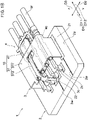
- FIG. 1A shows an electrical connection structure 1 according to the embodiment
- FIG. 1B shows the electrical connection structure 1 of FIG. 1A
- the electrical connection structure 1 according to the embodiment is a connection structure to electrically connect a plurality of electrical apparatuses via a pair of connectors (the connector 3 and the mating connector 4).
- the electrical connection structure 1 is an electrical connection structure for vehicle mounting, which electrical connection structure is to electrically connect between the electrical apparatuses mounted to an automobile.
- the electrical connection structure 1 comprises: a base member 2; a connector 3 being mounted to the base member 2 to be electrically connected thereto; and a mating connector 4 to be electrically connected to the connector 3 by being fitted thereto.
- the connector 3 and the mating connector 4 make up a so-called horizontal fitting type connector structure in which the mating connector 4 is fitted from the horizontal direction to a surface 2a of the base member 2, on which surface 2a the connector 3 is mounted.
- the connector 3 and the mating connector 4 can make up a so-called vertical fitting type connector structure in which the mating connector 4 is fitted from the vertical direction to the surface 2a of the base member 2, on which surface 2a the connector 3 is mounted.
- a direction in which the mating connector 4 is fitted toward the connector 3 is called a fitting direction D11, while a direction opposite to the fitting direction D11, in which direction the mating connector 4 is separated from the connector 3, is called a separating direction D12.
- both directions being the fitting direction D11 and the separating direction D12 are collectively called a fitting/ separating direction (first direction) D1.
- the fitting direction D11 and the separating direction D12 refer to one direction of directions being parallel to the surface 2a of the base member 2.
- one direction to cross the fitting/separating direction D1 is called a second direction D2.
- the second direction D2 can also be called a width direction.
- the second direction D2 is one direction of directions being parallel to the surface 2a of the base member 2 and a direction to cross the fitting/ separating direction D1. More specifically, the second direction D2 is one direction of directions being parallel to the surface 2a of the base member 2 and a direction being vertical to the fitting/separating direction D1. According to the specification, a direction to cross the fitting/ separating direction D1 and the second direction D2 is called a third direction D3.
- the third direction D3 can also be called a height direction. According to the embodiment, the third direction D3 is one direction of directions to cross the surface 2a of the base member 2 and a direction to cross the fitting/ separating direction D1.
- the third direction D3 is a direction being vertical to the surface 2a of the base member 2 and a direction being vertical to the fitting/ separating direction D1.
- a direction in which the connector 3 is mounted to the base member 2 can be called “lower” and the reverse thereof can be called “upper”.
- the electrical connection structure 1 comprises a half-fitting detecting mechanism 10 to detect whether the mating connector 4 is fitted in a normal fitting state/a half-fitting state.
- the half-fitting detecting mechanism 10 includes: a half-fitting detecting portion 31 provided in the connector 3; and a short-circuiting member 41 being electrically conductive and provided in the mating connector 4. The half-fitting detecting portion 31 and the short-circuiting member 41 will be described below.
- the above-mentioned normal fitting state refers to a state in which the connector 3 and the mating connector 4 are fitted to each other in a regular fitting position.
- the above-mentioned normal fitting state refers to a state in which, while the connector 3 and the mating connector 4 are close to being in the normal fitting state, but not completely fitted to each other, they are fitted to each other, but being fitted to each other while being in a position off the regular fitting position.
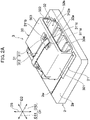
- FIG. 2A shows the base member 2 and the connector 3 included in the electrical connection structure 1 according to the embodiment
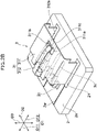
- FIG. 2B shows the base member 2 and the connector 3 of FIG. 2A , with a part of components (the housing 30 of the connector 3 to be described below) being omitted.
- the base member 2 is electrically connected to the connector 3 by the connector 3 being mounted thereto.
- the base member 2 is a wiring board.
- the base member 2 comprises a wiring 2w, a connecting portion for terminal 2c to be electrically connected to a contact 3c (see FIG.
- the connecting portion for mounting 21 and the connecting portion for inspecting 22 can be connected, via the wiring 2w, to a short-circuiting detecting circuit (not shown) to detect short circuiting between the electrically conductive member 311 and the inspecting member 312.
- the contact 3c, the electrically conductive member 311, and the inspecting member 312 of the connector 3 will be described below.
- the connector 3 is electrically connected to the base member 2 on one hand and is electrically connected to the mating connector 4 on the other hand.
- the connector 3 is a so-called surface mounting-type connector being mounted on the surface 2a of the base member 2 to be electrically connected to the base member 2.
- the connector 3 can be a connector being mounted to the base member 2 in a different form, such as a connector being mounted to a through hole or a notch provided in the base member 2 by being fitted thereto to be electrically connected to the base member 2.
- the connector 3 is a female connector, while the mating connector 4 is a male connector.
- the connector 3 can be the male connector, while the mating connector 4 can be the female connector.
- the connector 3 comprises a half-fitting detecting portion 31 to detect whether the mating connector 4 is fitted thereto in the normal fitting state.
- the half-fitting detecting portion 31 does not produce short circuiting in the interior thereof when the connector 3 and the mating connector 4 are in the half-fitting state, while the half-fitting detecting portion 31 produces short circuiting in the interior thereof via the short-circuiting member 41 of the mating connector 4 to be described below when the connector 3 and the mating connector 4 are in the normal fitting state. In this way, the half-fitting state of the connector 3 and the mating connector 4 can be sensed. Details of the half-fitting detecting portion 31 will be described below.
- the expression "the connector 3 and the mating connector 4 being fitted to each other” and that similar thereto refer to the connector 3 and the mating connector 4 being fitted to each other with the connector 3 (specifically, an inner surface of a fitting portion 32 of the connector 3 to be described below) and the mating connector 4 (specifically, an outer surface of a mating fitting portion 42 of the mating connector 4 to be described below) being physically in contact with each other in any one direction to cross the fitting/separating direction D1 (specifically, any direction being vertical to the fitting/ separating direction D1).
- the connector 3 (specifically, the inner surface of the fitting portion 32) and the mating connector 4 (specifically, the outer surface of the mating fitting portion 42) are in physical contact with each other to be fitted thereto in the second direction D2 and the third direction D3.
- the connector 3 comprises the housing 30.
- the housing 30 holds the half-fitting detecting portion 31.
- the housing 30 can further hold the contact 3c (see FIG. 2B ) to be described below.
- the housing 30 is formed with an insulating resin material, for example.
- the housing 30 has a first wall portion (side wall portion) 301 and a second wall portion 302 (side wall portion) to cross the second direction D2 (being orthogonal thereto in FIG. 2A ), and a third wall portion (top wall portion) 303 and a fourth wall portion 304 (bottom wall portion) to cross the third direction D3 (being orthogonal thereto in FIG. 2A ).
- the housing 30 comprises the fitting portion 32 to be fitted to the mating connector 4 (see FIG. 3 ).
- the fitting portion 32 is fitted to the mating fitting portion 42 (see FIG. 3 ) of the connector 4 to be described below.
- the connector 3 and the mating connector 4 can be electrically connected with a good connection reliability when the fitting portion 32 and the mating fitting portion 42 are fitted to each other in the normal fitting state.
- the fitting portion 32 is provided on the separating direction D12 side of the housing 30, and the mating connector 4 (see FIG. 3 ) fits thereto from the fitting direction D11.
- the fitting portion 32 is a fitting concave portion extending along the fitting/ separating direction D1, which fitting concave portion has a housing space 32h into which housing space 32h the mating fitting portion 42 can be inserted and which housing space 32h can house the mating fitting portion 42, which mating fitting portion 42 is formed as a fitting convex portion.
- the housing space 32h is defined by inner surfaces of the first wall portion 301, the second wall portion 302, the third wall portion 303, and the fourth wall portion 304.
- the fitting portion 32 has, on the fitting direction D11 side within the housing space 32h, an opposing wall portion 305 (not shown in FIG. 2A ; see FIG. 4A ) crossing the fitting/separating direction D1 (specifically, being orthogonal thereto) and opposing a mating opposing wall portion 405 (see FIGS. 3 and 4A ) of the mating fitting portion 42.
- the connector 3 and the mating connector 4 can be in the normal fitting state when the opposing wall portion 305 and the mating opposing wall portion 405 are in contact with each other, or when they are almost in contact with each other.
- the fitting portion 32 has a guide portion 32a to guide the mating connector 4 (see FIG. 3 ) in the fitting/separating direction D1.
- the fitting portion 32 having the guide portion 32a allows the mating connector 4 being forcibly fitted to the connector 3 in a direction oblique to the fitting/ separating direction D1 to be suppressed, making it easy for the connector 3 and the mating connector 4 to be fitted to each other in the normal fitting state.
- the guide portion 32a is a guide ridge to guide a mating guide portion 42a of the mating fitting portion 42, which mating guide portion 42a is formed as a guide groove, and is provided so as to extend along the fitting/ separating direction D1 at an inner surface of the fitting portion 32.
- the guide portion 32a can be provided as the guide groove, while the mating guide portion 42a can be provided as the guide ridge. Moreover, while the guide portion 32a is provided in a plurality (four in FIG. 2A ) on the inner surface of the fourth wall portion (bottom wall portion) 304 in FIG. 2A , the arrangement and the number of the guide portion 32a are not particularly limited as long as it does not hinder detecting of the half-fitting state by the half detecting portion 31.
- the connector 3 comprises the contact 3c to be electrically connected to the base member 2 and the mating connector 4 (see FIG. 3 ).
- the contact 3c is electrically connected to a mating contact 4c (see FIG. 3 ) on the separating direction D12 side by being in contact therewith and is electrically connected to the connecting portion for terminal 2c of the base member 2 on the fitting direction D11 side by a solder.
- the contact 3c is formed with an electrically conductive metal material, for example.
- the contact 3c is a male contact, and, when the mating connector 4 is fitted to the connector 3, it is inserted into the mating contact 4c to be electrically connected thereto, which mating contact 4c is a female contact of the mating connector 4 to be described below.
- the mating contact 4c can also be configured to be the male contact.
- the shape of the contact 3c is not particularly limited, according to the embodiment, the contact 3c extends along the fitting/ separating direction D1 and is formed in a shape of a pin to be inserted through the housing 30 (see FIG. 2A ). In FIG.
- the contact 3c is provided in a plurality (specifically, 1 x 4, or four) such that it projects into the housing space 32h of the fitting portion 32.
- the singular contact 3c can be provided, so that the number and arrangement (for example, the number of rows and columns) of the contact 3c are appropriately changed depending on the use of the electrical connection structure 1.
- the half-fitting detecting portion 31 is a portion to detect the half-fitting state of the connector 3 and the mating connector 4.
- the half-fitting detecting portion 31 can detect the half-fitting state by the short-circuiting member 41 of the mating connector 4 being in non-contact with an inspecting member 312 as described below when the mating connector 4 is fitted to the connector 3 in the half-fitting state.
- the half-fitting detecting portion 31 includes an electrically conductive member 311 to be in contact with the short-circuiting member 41 and the electrically conductive inspecting member 312 provided in a non-contact state with respect to the electrically conductive member 311.
- the electrically conductive member 311 is a member to mount the connector 3 to the base member 2.
- the electrically conductive member 311 is electrically connected to the base member 2.
- the connector 3 With the electrically conductive member 311 being provided, the connector 3 is allowed to be connected to the base member 2 not only with the contact 3c, but also with the electrically conductive member 311, so that the strength of connection of the connector 3 to the base member 2 increases, and the connection reliability also improves.
- the mating connector 4 see FIG. 3
- the electrically conductive member 311 is in contact with the short-circuiting member 41 of the mating connector 4.
- the shape and arrangement of the electrically conductive member 311 is not particularly limited.
- the electrically conductive member 311 is formed with a bent metal plate and has a C letter shape so as to surround the contact 3c as viewed from the fitting/ separating direction D1.
- the electrically conductive member 311 is connected to the connecting portion for mounting 21 of the base member 2 at both ends of the housing 30 in the second direction D2 as viewed from the fitting/separating direction D1.
- the electrically conductive member 311 can be provided so as to be positioned on an inner surface of the housing 30 of the connector 3 such that it makes up at least a part of the fitting portion 32.
- the fitting portion 32 no other member is interposed between the mating connector 4 and the electrically conductive member 311, so that misalignment of the electrically conductive member 311 with respect to the fitting portion 32 due to a dimensional error of the other member is suppressed.
- detecting of the half-fitting state by the half-fitting detecting portion 31 can be carried out with high accuracy.
- the electrically conductive member 311 is provided so as to be positioned on an inner surface of the housing 30 of the connector 3 in the second direction D2 and the third direction D3.
- the electrically conductive member 311 is provided so as to be positioned on inner surfaces of the first wall portion 301, the second wall portion 302, and the third wall portion 303. In this case, in the two directions (the second direction D2 and the third direction D3), misalignment of the electrically conductive member 311 is suppressed, making it possible to further carry out, with high accuracy, detecting of the half-fitting state by the half-fitting detecting portion 31.
- the electrically conductive member 311 can be provided so as to be positioned on an inner surface of any one of the first wall portion 301, the second wall portion 302, the third wall portion 303, and the fourth wall portion 304. Moreover, the electrically conductive member 311 can be buried into the housing 30 without being exposed from the inner surface of the housing 30.
- the electrically conductive member 311 has an engaging portion 311a (see FIG. 2B ) to engage with the short-circuiting member 41 (see FIG. 3 ) of the mating connector 4.
- the engaging portion 311a can also be formed in a portion of the connector 3 other than the electrically conductive member 311, such as the housing 30, for example.
- the engaging portion 311a engages with a mating engaging portion 41a of the mating connector 4.
- the engaging portion 311a being engaged with the mating engaging portion 41a allows separating of the mating connector 4 from the connector 3 to be suppressed.
- the engaging portion 311a engages with the mating engaging portion 41a when the mating connector 4 is fitted to the connector 3 in the normal fitting state.
- the engaging portion 311a engaging with the mating engaging portion 41a makes it possible to hold a connection between the connector 3 and the mating connector 4 in the normal fitting state.
- the engaging portion 311a is provided in the electrically conductive member 311.
- the engaging portion 311a is an engaging concave portion formed with a through hole 311b, which engaging concave portion is to engage with the mating engaging portion 41a as an engaging convex portion.
- the engaging portion 311a is an inner wall on the separating direction D12 side of the through hole 311b and engages with a wall portion on the separating direction D12 side of the mating engaging portion 41a being an engaging convex portion.
- the electrically conductive member 311 has the through hole 311b being provided in correspondence with the contact part 312a of the inspecting member 312 to be described below.
- the through hole 311b provides a space that can be accessible by both the short-circuiting member 41 of the mating connector 4 and the inspecting member 312.
- the through hole 311b is provided in shape and size that can house therein the contact part 312a and the mating engaging portion 41a of the short-circuiting member 41.
- the mating connector 4 is arranged to be fitted to the connector 3 in a regular fitting position when the mating engaging portion 41a is housed in the through hole 311b.
- the through hole 311b is formed in a shape (pentagonal shape), which pentagonal shape and a shape projecting in the third direction D3 (upward direction) of the mating engaging portion 41a are fitted to each other.
- the shape and size of the through hole 311b are not particularly limited as long as the through hole 311b can provide access to the short-circuiting member 41 and the inspecting member 312. According to the embodiment, as shown in FIG.
- the through hole 311b is provided at the center of the third wall portion 303 in the second direction D2, which third wall portion 303 is formed with the electrically conductive member 311. Moreover, according to the embodiment, as shown in FIG. 2B , the through hole 311b is provided toward the separating direction D12 in the electrically conductive member 311. However, the arrangement of the through hole 311b is appropriately changed depending on the arrangement of the short-circuiting member 41 and the inspecting member 312.
- the electrically conductive member 311 has an abutting portion 311c to abut on the short-circuiting member 41.
- the abutting portion 311c short-circuits between the electrically conductive member 311 and the short-circuiting member 41 by abutting on the short-circuiting member 41 of the mating connector 4.
- the abutting portion 311c is formed with the electrically conductive member 311 being positioned on an inner surface of the housing 30, and is provided on at least one of the fitting direction D11 side and the separating direction D12 side with respect to the through hole 311b.
- the abutting portion 311c is provided on the separating direction D12 side of an inner surface of the third wall portion 303, which inner surface is formed with the electrically conductive member 311.
- the inspecting member 312 is a member to inspect a fitting state of the connector 3 and the mating connector 4.
- the inspecting member 312 short-circuits with the electrically conductive member 311 via the short-circuiting member 41 of the mating connector 4.
- the shape and arrangement of the inspecting member 312 are not particularly limited as long as the inspecting member 312 can be in contact with the short-circuiting member 41. According to the embodiment, as shown in FIGS. 2A and 2B (see also FIG.
- the inspecting member 312 extends along the fitting/separating direction D1, the end on the fitting direction D11 side is electrically connected to the base member 2, and the end (a contact part 312a to be described below) on the separating direction D12 side is arranged in correspondence with the through hole 311b of the electrically conductive member 311.
- the inspecting member 312 is formed in an L letter shape as viewed from the second direction D2, extends along the third direction D3 such that it extends along a rear surface (surface on the fitting direction D11 side) of the housing 30 on one end side (fitting direction D11 side), and extends along the fitting/ separating direction D1 such that it extends at a distance with respect to an outer surface of the electrically conductive member 311 on the other end side (separating direction D12 side).
- the inspecting member 312 bends, on the other end side, in the third direction (downward direction) D3 after extending along the separating direction D12 such that the end of the other end side is housed in the through hole 311b.
- the inspecting member 312 has a contact part 312a to be in contact with the short-circuiting member 41.
- the contact part 312a is in contact with the mating engaging portion 41a (see FIG. 3 ) of the mating connector 4.
- the contact part 312a is provided at the end on the separating direction D12 side of the inspecting member 312.
- the contact part 312a can be in contact with the mating engaging portion 41a, it is not particularly limited and can be provided in a different form, such as, when the inspecting member 312 is bent in a V letter shape on the separating direction D12 side, the contact part 312a being provided in a portion being bent as mentioned above.
- the short-circuiting direction of the half-fitting detecting portion 31 and the short-circuiting member 41 and the fitting/ separating direction D1 of the connector 3 and the mating connector 4 match each other, making it easy to design a short-circuiting form of the half-fitting detecting portion 31 and the short-circuiting member 41 in accordance with a fitting form of the connector 3 and the mating connector 4.
- FIG. 3 shows the mating connector 4 included in the electrical connection structure 1 according to the embodiment.
- the mating connector 4 is fitted/ separated in the fitting/ separating direction D1 with respect to the connector 3 (see FIG. 2A ).
- the mating connector 4 can be electrically connected to the connector 3 by being fitted to the connector 3 from the fitting direction D11 and can release an electrical connection to the connector 3 by being separated from the connector 3 in the separating direction D12.
- the mating connector 4 is a so-called electrical wire connection-type connector being, on one hand, electrically connected to the connector 3 and, on the other hand, electrically connected to an electrical wire W.
- the mating connector 4 can be a connector of a different form, such as the above-described surface mounting-type connector to be electrically connected to a base member (specifically, a wiring board).
- the mating connector 4 comprises an electrically connecting short-circuiting member 41.
- the short-circuiting member 41 is not in contact with the inspecting member 312 (see FIG. 2A ) when the connector 3 (see FIG. 2A ) and the mating connector 4 are in the half-fitting state, while it is in contact with the inspecting member 312 when it is in the normal fitting state. In this way, the half-fitting state of the connector 3 and the mating connector 4 can be sensed.
- the mating connector 4 comprises a mating housing 40 to hold the short-circuiting member 41.
- the mating housing 40 can further hold the mating contact 4c as described below.
- the mating housing 40 is formed with an insulating resin material, for example.
- the mating housing 40 has a first mating wall portion (side wall portion) 401 and a second mating wall portion (side wall portion) 402 to cross the second direction D2 (being orthogonal in FIG. 3 ), and a third mating wall portion (top wall portion) 403 and a fourth mating wall portion (bottom wall portion) 404 to cross the third direction D3 (being orthogonal in FIG. 3 ).
- the mating housing 40 comprises a mating fitting portion 42 to be fitted to the connector 3 (see FIG. 2A ).
- the mating fitting portion 42 is a portion to be fitted to the fitting portion 32 (see FIG. 2A ) of the connector 3.
- the mating fitting portion 42 is provided on the fitting direction D11 side of the mating housing 40 and fitted to the connector 3 from the fitting direction D11.
- the mating fitting portion 42 is a fitting convex portion extending along the fitting/separating direction D1, which fitting convex portion can be inserted into and housed in the housing space 32h (see FIG. 2A ) of the fitting portion 32 formed as a fitting concave portion.
- the mating fitting portion 42 has a parallelepiped shape defined by the first mating wall portion 401, the second mating wall portion 402, the third mating wall portion 403, and the fourth mating wall portion 404.
- the mating fitting portion 42 has, on the fitting direction D11 side, the mating opposing wall portion 405 to cross the fitting/separating direction D1 (specifically, being orthogonal thereto) and oppose the opposing wall portion 305 (see FIG. 4A ) of the fitting portion 32.
- the mating fitting portion 42 has the mating guide portion 42a to be guided in the fitting/separating direction D1 by the connector 3 in correspondence with the guide portion 32a of the connector 3.
- the mating guide portion 42a is provided in a plurality (four in FIG. 2A ) as a guide groove extending along the fitting/ separating direction D1 at an outer surface of the fourth mating wall portion 404 of the mating fitting portion 42 in correspondence with the guide portion 32a of the connector 3.
- the shape and arrangement, and the number of the mating guide portion 42a are appropriately changed depending on the shape, the number, and the arrangement of the guide portion 32a of the connector 3.
- the mating connector 4 comprises the mating contact 4c to be electrically connected to the connector 3 (see FIG. 2A ).
- the mating contact 4c is electrically connected to the contact 3c (see FIG. 2B ) of the connector 3 on the fitting direction D11 side by being in contact therewith and is electrically connected to the electrical wire W on the separating direction D12 side by crimping.
- the mating contact 4c is formed with an electrically conductive metal material, for example.
- the mating contact 4c is electrically connected to the contact 3c when the mating connector 4 is fitted to the connector 3. While the mating contact 4c is provided in a plurality (specifically, 1 x 4, or four) in FIG. 3 , only one thereof can be provided, so that the number and arrangement (for example, the number of rows and columns) of the mating contact 4c are appropriately changed depending on the number and arrangement of the contact 3c of the connector 3.
- the short-circuiting member 41 is a member to short circuit with the half-fitting detecting portion 31 of the connector 3.
- the short-circuiting member 41 is in contact with the electrically conductive member 311 and the inspecting member 312 to short-circuit the electrically conductive member 311 and the inspecting member 312 when the mating connector 4 is fitted to the connector 3 in the normal fitting state, while the short-circuiting member 41 is in non-contact with the inspecting member 312 not to short-circuit the electrically conductive member 311 and the inspecting member 312 when it is fitted thereto in the half-fitting state.
- the inspecting member 312 and the electrically conductive member 311 are short circuited via the short-circuiting member 41 in the normal fitting state, while the inspecting member 312 and the electrically conductive member 311 are not short-circuited in the half-fitting state. In this way, the fitting state of the connector 3 and the mating connector 4 can be detected.
- the short-circuiting member 41 is a cantilevered elastic member being provided at the center of the third mating wall portion 403 in the fitting/ separating direction D1 and the second direction D2 and extending in the fitting/ separating direction D1.
- the short-circuiting member 41 is formed with one metal plate having a shape of an arm extending from the fixed end side to the free end side toward the separating direction D12 while slightly being inclined to the third direction (upward direction) D3 side.
- the shape and arrangement of the short-circuiting member 41 is not particularly limited as long as the short-circuiting member 41 can be in contact with the inspecting member 312 and the electrically conductive member 311 in the normal fitting state.
- the short-circuiting member 41 has the mating engaging portion 41a to engage with the electrically conductive member 311 (see FIG. 2A ).
- the mating engaging portion 41a engages with the engaging portion 311a (see FIG. 2A ) of the electrically conductive member 311, and is also in contact with the contact part 312a of the inspecting member 312.
- the mating engaging portion 41a is an engaging convex portion formed with a projecting portion of the short-circuiting member 41, which projecting portion projects in the third direction (upward direction) D3 and engages with the engaging portion 311a as an engaging concave portion.
- the mating engaging portion 41a is a wall portion on the separating direction D12 side of the projecting portion.
- the mating engaging portion 41a is integrally formed with the short-circuiting member 41 being a metal plate.
- the mating engaging portion 41a can demonstrate a sufficient locking capability, and also has a holding force of engaging with the engaging portion 311a.
- the mating engaging portion 41a is in sliding contact with the electrically conductive member 311 on the separating direction D12 side with respect to the through hole 311b by the short-circuiting member 41 being pressed against the electrically conductive member 311 to be elastically deformed when the mating connector 4 moves in the fitting direction D11 to be fitted to the connector 3.
- the length of the abutting portion 311c (the length between the through hole 311b and the end edge of the electrically conductive member 311 in the separating direction D12) is less.
- the distance in which the mating engaging portion 41a and the abutting portion 311a are in sliding contact with each other is less, so that a sense of incongruity due to a sliding contact at the time of operation of the mating connector 4 being fitted to the connector 3 can be suppressed.
- the mating engaging portion 41a is in contact with the contact part 312a of the inspecting member 312.
- the short-circuiting member 41 has a function to engage with the electrically conductive member 311 and a function to be in contact with the inspecting member 312.
- the mating engaging portion 41a is in contact with the contact part 312a by the short-circuiting member 41 being elastically restored such that it is positioned in the through hole 311b when the mating connector 4 is fitted to the connector 3 in the normal fitting state.
- the short-circuiting member 41 has an operating portion 41b that can release engaging of the connector 3 (see FIG. 2A ) and the mating connector 4 with a pressing operation.
- the short-circuiting member 41 having the operating portion 41b makes it easy to release engaging of the connector 3 and the mating connector 4, also making it easy to remove the mating connector 4 from the connector 3.
- the operating portion 41b is provided on the separating direction D12 side of the short-circuiting member 41 being exposed in the fitting state such that it can be easily operated in the normal fitting state of the connector 3 and the mating connector 4.
- engaging of the engaging portion 311a and the mating engaging portion 41a is released by pressing the operating portion 41b in the third direction (downward direction) D3, making it possible to remove the mating connector 4 from the connector 3.
- the short-circuiting member 41 has the short-circuiting portion 41c to abut on the electrically conductive member 311 (see FIG. 2A ) of the connector 3 in the normal fitting state. Specifically, the short-circuiting portion 41c abuts on the abutting portion 311c (see FIG. 2A ) of the electrically conductive member 311. According to the embodiment, the short-circuiting portion 41c is provided on at least one of the fitting direction D11 side and the separating direction D12 side with respect to the mating engaging portion 41a. In FIG.
- the short-circuiting portion 41c is provided on the separating direction D12 side of the mating engaging portion 41a, and more specifically, is provided in the short-circuiting member 41 between the mating engaging portion 41a and the operating portion 41b.
- the position of the short-circuiting portion 41c is appropriately changed in accordance with the position of the abutting portion 311c in the connector 3.
- FIGS. 4A to 6B one example of a method of detecting the fitting state in the electrical connection structure 1 according to the embodiment will be described.
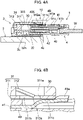
- FIGS. 4A , 5A , and 6A is a cross-sectional view in which the central axis of the second contact 3c from the front of the paper is cut in a cross section being vertical to the second direction D2 in FIG. 1A .
- FIGS. 4B , 5B , and 6B is an enlarged view of a 4B portion, a 5B portion, and a 6B portion in FIG. 4A , 5A , and 6A .
- the method of detecting of the fitting state in the electrical connection structure 1 shown below is merely exemplary, so that the electrical connection structure according to the disclosure is not limited to the embodiment below.
- the mating fitting portion 42 starts to be fitted to the fitting portion 32 and the mating contact 4c starts to be fitted to the contact 3c.
- the mating engaging portion 41a of the mating connector 4 abuts on the opening edge (side wall on the separating direction D12 side of the electrically conductive member 311) of the connector 3.
- the mating engaging portion 41a of the short-circuiting member 41 moves while it is in sliding contact with the electrically conductive member 311 on the separating direction D12 side with respect to the through hole 311b by being elastically deformed in the third direction (downward direction) D3 by pressing.
- the short-circuiting member 41 has a shape of an arm in which the free end side extends toward the separating direction D12, so that the free end side is elastically deformed easily in the third direction (downward direction) D3 by pressing.
- the mating engaging portion 41a moves to a position corresponding to the though hole 311b.
- the mating engaging portion 41a intrudes into the through hole 311b to be housed therein by the short-circuiting member 41 being elastically restored such that it is released from pressing by the abutting portion 311c.
- the mating connector 4 is fitted to the connector 3 in the normal fitting state and the mating contact 4c is electrically connected to the contact 3c in the normal state.
- the mating engaging portion 41a is in contact with the contact part 312a being arranged at a position corresponding to the through hole 311b (specifically being arranged in the through hole 311b) and presses the contact part 312a in the third direction (upward direction) D3 to elastically deform the contact part 312a.
- the short-circuiting member 41 is in contact with the electrically conductive member 311 at the short-circuiting portion 41c.
- the mating engaging portion 41a in the half-fitting state shown in FIGS. 5A and 5B , for example, the mating engaging portion 41a does not intrude into the through hole 311b, so that the mating engaging portion 41a is not in contact with the contact part 312a.
- the inspecting member 312 in the half-fitting state, does not also short-circuit with the electrically conductive member 311. In this way, the half-fitting state can be sensed in accordance with whether the electrically conductive member 311 and the inspecting member 312 are short-circuited.
- the mating engaging portion 41a engages with the engaging portion 311a in the separating direction D12.
- the normal fitting state can be held by engaging of the engaging portion 311a and the mating engaging portion 41a.
- the engaging of the engaging portion 311a and the mating engaging portion 41a can be released by an operation of pressing the operating portion 41b.
- the mating connector 4 can easily be removed from the connector 3 by pulling out the mating connector 4 in the separating direction D12 while pressing the operating portion 41b.
- the short-circuiting member 41 extending in the fitting/ separating direction D1 has a fixed end on the fitting direction D11 side and a free end on the separating direction D12 side in FIGS. 4A to 6B , it can have a free end on the fitting direction D11 side and a fixed end on the separating direction D12 side.
- the shape of the short-circuiting member 41 is not limited to the shape shown. For example, in FIGS.
- the short-circuiting member 41 toward the free end side (separating direction D12 side) from the fixed end side (the fitting direction D11 side), the short-circuiting member 41 has a shape of an arm extending toward the upward direction (one direction of the third directions D3). However, toward the free end side (separating direction D12 side) from the fixed end side (the fitting direction D11 side), the short-circuiting member 41 can have a shape of an arm extending toward the downward direction (one direction of the third directions D3).
- the short-circuiting member 41 can be in contact with an inner surface of the electrically conductive member 311 on the fitting direction D11 side of the through hole 311b, so that the abutting portion 311c can be provided on the fitting direction D11 side of the through hole 311b.
- the short-circuiting member 41 can have a shape of an arm extending toward the free end side (the separating direction D12 side) from the fixed end side (the fitting direction D11 side) while maintaining the position in the third direction D3.
- the short-circuiting member 41 can be in contact with an inner surface of the electrically conductive member 311 on either one of the fitting direction D11 side and the separating direction D12 side of the through hole 311b, so that the abutting portion 311c can be provided on the fitting direction D11 side and the separating direction D12 side of the through hole 311b.
- the shape of the short-circuiting member 41 can be selected from various shapes.
- the inspecting member 312 short-circuits with the electrically conductive member 311 via the short-circuiting member 41 by the mating engaging portion 41a of the short-circuiting member 41 being engaged with the engaging portion 311a of the connector 3 and being in contact with the contact part 312a of the inspecting member 312, and the short-circuiting member 41 being in contact with the electrically conductive member 311.
- engaging between the mating engaging portion 41a and the engaging portion 311a and contacting between the mating engaging portion 41a and the contact part 312a occur at the same time.
- the length of the connector 3 in the width direction (second direction) D2 can change. Even in such a case, when the inspecting member 312 is connected to the base member 2 by extending along the fitting/ separating direction, not extending along the width direction D2, the inspecting member 312 can be shared without being influenced by the change in length of the connector 3 in the width direction D2.
- the inspecting member is provided so as to straddle the connector in the width direction.
- the short-circuiting member 41 of the mating connector 4 is formed with an electrically conductive member, or, specifically a metal plate, so that, even if it is downsized or slimmed, it can have a sufficient strength in comparison to a case in which it is formed with a resin material, for example.
- a sufficient locking function can be demonstrated even when the mating engaging portion 41a is downsized or slimmed.
- the electrically conductive member 311 is provided so as to be positioned on the inner surface of the housing 30 of the connector 3 such that it makes up at least a part of the fitting portion 32 to be fitted to the mating connector 4.
- the electrically conductive member 311 is provided so as to be positioned on the inner surface of the housing 30 of the connector 3 such that it makes up at least a part of the fitting portion 32 to be fitted to the mating connector 4.
- no other member is interposed.
- misalignment of the electrically conductive member 311 with respect to the fitting portion 32 which misalignment is due to a dimensional error of a different member, is suppressed, and, consequently, it is made possible to detect the half-fitting state by the half-fitting detecting portion 31 with high accuracy.
- the contact portion of the contact part 312a and the mating engaging portion 41a and the contact portion of the electrically conductive member 311 and the short-circuiting member 41 are lined up at a distance along the fitting/ separating direction D1.
- the direction of short-circuiting of the half-fitting detecting portion 31 and the short-circuiting member 41 and the fitting/ separating direction D1 of the connector 3 and the mating connector 4 match each other, making it easy to design a short-circuiting form of the half-fitting detecting portion 31 and the short-circuiting member 41 in accordance with the fitting form of the connector 3 and the mating connector 4.
- the short-circuiting member 41 of the mating connector 4 is a cantilevered elastic member extending in the fitting/ separating direction D1, while the mating engaging portion 41a is in sliding contact with the electrically conductive member 311 on the separating direction D12 with respect to the through hole 311b by the short-circuiting member 41 being pressed against the electrically conductive member 311 to be elastically deformed when the mating connector 4 moves in the fitting direction D11 to be fitted to the connector 3.
- the mating engaging portion 41a is in contact with the contact part 312a by the short-circuiting member 41 being elastically restored such that the mating engaging portion 41a is positioned in the through hole 311b when the mating connector 4 is fitted to the connector 3 in the normal fitting state.
- providing the through hole 311b in the electrically conductive member 311 and configuring the short-circuiting member 41 to be the cantilevered elastic member make it possible to provide a detecting function and an engaging function in a simple structure.
Landscapes
- Details Of Connecting Devices For Male And Female Coupling (AREA)
Abstract
Description
- The disclosure relates to an electrical connection structure.
- In an electrical connection structure using connectors, generally, a connector and a mating connector are electrically connected to each other by the connector and the mating connector being fitted thereto. A state in which the connector and the mating connector are not fitted to each other in a normal fitting state, such as connector and the mating connector being fitted to each other in a fitting length being slightly shorter than a regular fitting length, for example, is called a half-fitting state. In the half-fitting state, the connector and the mating connector receive an undesirable influence such as a reduction in the electrical connection reliability. However, the half-fitting state can be indistinguishable from the normal fitting state in appearance. Thus, a connector that can detect the half-fitting state is called for.
-
Japanese Patent Application Publication No. 2019-040746 Japanese Patent Application Publication No. 2019-040746 Japanese Patent Application Publication No. 2019-040746 - In an electrical connection structure using connectors, generally, a connector and a mating connector being engaged with each other in a normal fitting state causes the connector and the mating connector being separated from each other to be suppressed and an electrical connection to be held. According to the electrical connection structure of
Japanese Patent Application Publication No. 2019-040746 - Then, in view of such problems as described above, an object of the disclosure is to provide an electrical connection structure that can reliably detect a half-fitting state.
- An electrical connection structure according to one embodiment of the disclosure comprises: a base member; a connector being mounted to the base member to be electrically connected thereto; and a mating connector to be fitted/ separated in a fitting/separating direction with respect to the connector and to be electrically connected to the connector by being fitted thereto, wherein the electrical connection structure comprises a half-fitting detecting mechanism to detect whether the mating connector is fitted in a normal fitting state; the half-fitting detecting mechanism includes: a half-fitting detecting portion being provided in the connector; and a short-circuiting member being electrically conductive and provided in the mating connector, wherein the half-fitting detecting portion includes: an electrically conductive member being electrically connected to the base member to be in contact with the short-circuiting member of the mating connector to electrically connect the short-circuiting member and the base member; and an inspecting member being electrically conductive, having a contact part to be in contact with the short-circuiting member, and being provided in a non-contact state with respect to the electrically conductive member; wherein the half-fitting detecting portion allows a half-fitting state to be detected by the short-circuiting member being in non-contact with the inspecting member when the mating connector is fitted to the connector in the half-fitting state, wherein the connector has an engaging portion to engage with a mating engaging portion of the short-circuiting member to suppress separating of the mating connector, and wherein the inspecting member short-circuits with the electrically conductive member via the short-circuiting member by the mating engaging portion being engaged with the engaging portion and being in contact with the contact part and the short-circuiting member being in contact with the electrically conductive member when the mating connector is fitted to the connector in the normal fitting state.
- In one embodiment, the electrically conductive member can make up at least a part of a fitting portion to be fitted to the mating connector.
- In one embodiment, a contact portion of the contact part and the mating engaging portion and a contact portion of the electrically conductive member and the short-circuiting member can be lined up at a distance along the fitting/ separating direction when they are in the normal fitting state.
- In one embodiment, the inspecting member can extend along the fitting/ separating direction, and an end on the fitting direction side of the inspecting member can be electrically connected to the base member.
- In one embodiment, the contact part can be provided at an edge on the separating direction side of the inspecting member, wherein the electrically conductive member has: a through hole being provided so as to be positioned on an inner surface of a housing of the connector and being provided in correspondence with the contact part; and an abutting portion to abut on the short-circuiting member, on at least one of the fitting direction side and the separating direction side with respect to the through hole, wherein the short-circuiting member is a cantilevered elastic member extending in the fitting/ separating direction, wherein the short-circuiting member has a short-circuiting portion on at least one of the fitting direction side and the separating direction side with respect to the mating engaging portion, which short-circuiting portion is to abut on the abutting portion in the normal fitting state, wherein the mating engaging portion is in sliding contact with the electrically conductive member on the separating direction side with respect to the through hole by the short-circuiting member being pressed against the electrically conductive member to be elastically deformed when the mating connector moves in the fitting direction to be fitted to the connector, and the inspecting member short-circuits with the electrically conductive member via the short-circuiting member by the mating engaging portion being elastically restored so as to be positioned in the through hole to be in contact with the contact part and the short-circuiting portion being in contact with the abutting portion when the mating connector is fitted to the connector in the normal fitting state.
- The electrical connection structure according to one embodiment of the disclosure makes it possible to provide an electrical connection structure that can reliably detect a half-fitting state.
-
-
FIG. 1A is a perspective view showing one example of an electrical connection structure according to one embodiment of the disclosure. -
FIG. 1B is a perspective view in which a housing of a connector and a mating housing of a mating connector are removed fromFIG. 1A . -
FIG. 2A is a perspective view showing one example of the connector of the electrical connection structure according to one embodiment of the disclosure. -
FIG. 2B is a perspective view in which the housing of the connector is removed fromFIG. 2A . -
FIG. 3 is a perspective view showing one example of the mating connector of the electrical connection structure according to one embodiment of the disclosure. -
FIG. 4A is a cross-sectional view showing one example of a state in the middle of fitting of the electrical connection structure according to one embodiment of the disclosure. -
FIG. 4B is an enlarged view of a 4B portion of 4A. -
FIG. 5A is a cross-sectional view showing a state in the middle of fitting of the electrical connection structure, in which state the mating connector moved in a fitting direction with respect to the connector from the state shown inFIG. 4A . -
FIG. 5B is an enlarged view of a 5B portion of 5A. -
FIG. 6A is a cross-sectional view showing one example of a normal fitting state of the electrical connection structure according to one embodiment of the disclosure. -
FIG. 6B is an enlarged view of a 6B portion of 6A. - With reference to
FIGS. 1 to 3 , an electrical connection structure according to one embodiment of the disclosure will be described. The embodiment shown below is merely one example, so that the electrical connection structure according to the disclosure is not limited to the embodiment below. In the specification, the expression "vertical to A" and that being similar thereto are to refer not only to a direction being completely vertical to A, but are to refer to include that they are substantially vertical to A. Moreover, in the specification, the expression "parallel to B" and that being similar thereto are to refer not only to a direction being completely parallel to B, but are to refer to include that they are substantially parallel to B. Furthermore, in the specification, the expression "C shape" and that being similar thereto are to refer not only to a complete C shape, but are to refer to include a shape that may remind the C shape in appearance (a substantially C shape), such as a shape in which a corner portion of the C shape is chamfered. - (Electrical connection structure according to the embodiment)
-
FIG. 1A shows anelectrical connection structure 1 according to the embodiment, whileFIG. 1B shows theelectrical connection structure 1 ofFIG. 1A , with a part of components (ahousing 30 of aconnector 3 and ahousing 40 of amating connector 4 to be described below) being omitted therein. As shown inFIGS. 1A and1B , theelectrical connection structure 1 according to the embodiment is a connection structure to electrically connect a plurality of electrical apparatuses via a pair of connectors (theconnector 3 and the mating connector 4). While the use of theelectrical connection structure 1 is not particularly limited, according to the embodiment, theelectrical connection structure 1 is an electrical connection structure for vehicle mounting, which electrical connection structure is to electrically connect between the electrical apparatuses mounted to an automobile. Theelectrical connection structure 1 comprises: abase member 2; aconnector 3 being mounted to thebase member 2 to be electrically connected thereto; and amating connector 4 to be electrically connected to theconnector 3 by being fitted thereto. According to the embodiment, theconnector 3 and themating connector 4 make up a so-called horizontal fitting type connector structure in which themating connector 4 is fitted from the horizontal direction to asurface 2a of thebase member 2, on whichsurface 2a theconnector 3 is mounted. However, theconnector 3 and themating connector 4 can make up a so-called vertical fitting type connector structure in which themating connector 4 is fitted from the vertical direction to thesurface 2a of thebase member 2, on whichsurface 2a theconnector 3 is mounted. - According to the specification, a direction in which the
mating connector 4 is fitted toward theconnector 3 is called a fitting direction D11, while a direction opposite to the fitting direction D11, in which direction themating connector 4 is separated from theconnector 3, is called a separating direction D12. Moreover, according to the specification, both directions being the fitting direction D11 and the separating direction D12 are collectively called a fitting/ separating direction (first direction) D1. According to the embodiment, the fitting direction D11 and the separating direction D12 refer to one direction of directions being parallel to thesurface 2a of thebase member 2. According to the specification, one direction to cross the fitting/separating direction D1 is called a second direction D2. The second direction D2 can also be called a width direction. According to the embodiment, the second direction D2 is one direction of directions being parallel to thesurface 2a of thebase member 2 and a direction to cross the fitting/ separating direction D1. More specifically, the second direction D2 is one direction of directions being parallel to thesurface 2a of thebase member 2 and a direction being vertical to the fitting/separating direction D1. According to the specification, a direction to cross the fitting/ separating direction D1 and the second direction D2 is called a third direction D3. The third direction D3 can also be called a height direction. According to the embodiment, the third direction D3 is one direction of directions to cross thesurface 2a of thebase member 2 and a direction to cross the fitting/ separating direction D1. More specifically, the third direction D3 is a direction being vertical to thesurface 2a of thebase member 2 and a direction being vertical to the fitting/ separating direction D1. According to the specification, in a case that terms of "upper" and "lower" are used, such as in "upper side" and "lower side", for example, a direction in which theconnector 3 is mounted to thebase member 2 can be called "lower" and the reverse thereof can be called "upper". - As shown in
FIGS. 1A and1B , theelectrical connection structure 1 comprises a half-fitting detectingmechanism 10 to detect whether themating connector 4 is fitted in a normal fitting state/a half-fitting state. The half-fitting detectingmechanism 10 includes: a half-fitting detectingportion 31 provided in theconnector 3; and a short-circuitingmember 41 being electrically conductive and provided in themating connector 4. The half-fitting detectingportion 31 and the short-circuitingmember 41 will be described below. - According to the specification, the above-mentioned normal fitting state refers to a state in which the
connector 3 and themating connector 4 are fitted to each other in a regular fitting position. On the other hand, the above-mentioned normal fitting state refers to a state in which, while theconnector 3 and themating connector 4 are close to being in the normal fitting state, but not completely fitted to each other, they are fitted to each other, but being fitted to each other while being in a position off the regular fitting position. -
FIG. 2A shows thebase member 2 and theconnector 3 included in theelectrical connection structure 1 according to the embodiment, whileFIG. 2B shows thebase member 2 and theconnector 3 ofFIG. 2A , with a part of components (thehousing 30 of theconnector 3 to be described below) being omitted. As shown inFIG. 2A and2B , thebase member 2 is electrically connected to theconnector 3 by theconnector 3 being mounted thereto. According to the embodiment, thebase member 2 is a wiring board. However, as long as thebase member 2 is electrically connected to theconnector 3 by theconnector 3 being mounted thereto, it is not limited to the wiring board. According to the embodiment, thebase member 2 comprises awiring 2w, a connecting portion for terminal 2c to be electrically connected to acontact 3c (seeFIG. 2B ) of theconnector 3; a connecting portion for mounting 21 to be electrically connected to an electricallyconductive member 311 of theconnector 3; and a connectingportion 22 for inspecting (seeFIG. 1B ) to be electrically connected to an inspectingmember 312 of theconnector 3. The connecting portion for mounting 21 and the connecting portion for inspecting 22 can be connected, via thewiring 2w, to a short-circuiting detecting circuit (not shown) to detect short circuiting between the electricallyconductive member 311 and the inspectingmember 312. Thecontact 3c, the electricallyconductive member 311, and the inspectingmember 312 of theconnector 3 will be described below. - As shown in
FIGS. 1A and1B , theconnector 3 is electrically connected to thebase member 2 on one hand and is electrically connected to themating connector 4 on the other hand. According to the embodiment, theconnector 3 is a so-called surface mounting-type connector being mounted on thesurface 2a of thebase member 2 to be electrically connected to thebase member 2. However, theconnector 3 can be a connector being mounted to thebase member 2 in a different form, such as a connector being mounted to a through hole or a notch provided in thebase member 2 by being fitted thereto to be electrically connected to thebase member 2. Moreover, according to the embodiment, as shown inFIG. 1B , theconnector 3 is a female connector, while themating connector 4 is a male connector. However, theconnector 3 can be the male connector, while themating connector 4 can be the female connector. - As shown in
FIGS. 1A and1B , theconnector 3 comprises a half-fitting detectingportion 31 to detect whether themating connector 4 is fitted thereto in the normal fitting state. The half-fitting detectingportion 31 does not produce short circuiting in the interior thereof when theconnector 3 and themating connector 4 are in the half-fitting state, while the half-fitting detectingportion 31 produces short circuiting in the interior thereof via the short-circuitingmember 41 of themating connector 4 to be described below when theconnector 3 and themating connector 4 are in the normal fitting state. In this way, the half-fitting state of theconnector 3 and themating connector 4 can be sensed. Details of the half-fitting detectingportion 31 will be described below. According to the specification, the expression "theconnector 3 and themating connector 4 being fitted to each other" and that similar thereto refer to theconnector 3 and themating connector 4 being fitted to each other with the connector 3 (specifically, an inner surface of afitting portion 32 of theconnector 3 to be described below) and the mating connector 4 (specifically, an outer surface of a matingfitting portion 42 of themating connector 4 to be described below) being physically in contact with each other in any one direction to cross the fitting/separating direction D1 (specifically, any direction being vertical to the fitting/ separating direction D1). According to the embodiment, the connector 3 (specifically, the inner surface of the fitting portion 32) and the mating connector 4 (specifically, the outer surface of the mating fitting portion 42) are in physical contact with each other to be fitted thereto in the second direction D2 and the third direction D3. - The
connector 3 comprises thehousing 30. According to the embodiment, as shown inFIG. 2A , thehousing 30 holds the half-fitting detectingportion 31. Thehousing 30 can further hold thecontact 3c (seeFIG. 2B ) to be described below. Thehousing 30 is formed with an insulating resin material, for example. InFIG. 2A , thehousing 30 has a first wall portion (side wall portion) 301 and a second wall portion 302 (side wall portion) to cross the second direction D2 (being orthogonal thereto inFIG. 2A ), and a third wall portion (top wall portion) 303 and a fourth wall portion 304 (bottom wall portion) to cross the third direction D3 (being orthogonal thereto inFIG. 2A ). - According to the embodiment, as shown in
FIG. 2A , thehousing 30 comprises thefitting portion 32 to be fitted to the mating connector 4 (seeFIG. 3 ). Specifically, thefitting portion 32 is fitted to the mating fitting portion 42 (seeFIG. 3 ) of theconnector 4 to be described below. Theconnector 3 and themating connector 4 can be electrically connected with a good connection reliability when thefitting portion 32 and themating fitting portion 42 are fitted to each other in the normal fitting state. InFIG. 2A , thefitting portion 32 is provided on the separating direction D12 side of thehousing 30, and the mating connector 4 (seeFIG. 3 ) fits thereto from the fitting direction D11. According to the embodiment, thefitting portion 32 is a fitting concave portion extending along the fitting/ separating direction D1, which fitting concave portion has ahousing space 32h into whichhousing space 32h themating fitting portion 42 can be inserted and whichhousing space 32h can house themating fitting portion 42, whichmating fitting portion 42 is formed as a fitting convex portion. InFIG. 2A , thehousing space 32h is defined by inner surfaces of thefirst wall portion 301, thesecond wall portion 302, thethird wall portion 303, and thefourth wall portion 304. - According to the embodiment, the
fitting portion 32 has, on the fitting direction D11 side within thehousing space 32h, an opposing wall portion 305 (not shown inFIG. 2A ; seeFIG. 4A ) crossing the fitting/separating direction D1 (specifically, being orthogonal thereto) and opposing a mating opposing wall portion 405 (seeFIGS. 3 and4A ) of themating fitting portion 42. According to the embodiment, theconnector 3 and themating connector 4 can be in the normal fitting state when the opposingwall portion 305 and the mating opposingwall portion 405 are in contact with each other, or when they are almost in contact with each other. - As shown in
FIG. 2A , according to the embodiment, thefitting portion 32 has aguide portion 32a to guide the mating connector 4 (seeFIG. 3 ) in the fitting/separating direction D1. Thefitting portion 32 having theguide portion 32a allows themating connector 4 being forcibly fitted to theconnector 3 in a direction oblique to the fitting/ separating direction D1 to be suppressed, making it easy for theconnector 3 and themating connector 4 to be fitted to each other in the normal fitting state. Moreover, themating connector 4 being forcibly fitted to theconnector 3 while it is turned upside down, or a mating connector that cannot be paired, such as a mating connector having the different number of contacts, for example, being forcibly fitted to theconnector 3 is suppressed, so that breaking of theconnector 3 due to forcible fitting is also suppressed. According to the embodiment, theguide portion 32a is a guide ridge to guide amating guide portion 42a of themating fitting portion 42, whichmating guide portion 42a is formed as a guide groove, and is provided so as to extend along the fitting/ separating direction D1 at an inner surface of thefitting portion 32. However, theguide portion 32a can be provided as the guide groove, while themating guide portion 42a can be provided as the guide ridge. Moreover, while theguide portion 32a is provided in a plurality (four inFIG. 2A ) on the inner surface of the fourth wall portion (bottom wall portion) 304 inFIG. 2A , the arrangement and the number of theguide portion 32a are not particularly limited as long as it does not hinder detecting of the half-fitting state by thehalf detecting portion 31. - According to the embodiment, as shown in
FIG. 2B , theconnector 3 comprises thecontact 3c to be electrically connected to thebase member 2 and the mating connector 4 (seeFIG. 3 ). Specifically, thecontact 3c is electrically connected to amating contact 4c (seeFIG. 3 ) on the separating direction D12 side by being in contact therewith and is electrically connected to the connecting portion forterminal 2c of thebase member 2 on the fitting direction D11 side by a solder. Thecontact 3c is formed with an electrically conductive metal material, for example. According to the embodiment, thecontact 3c is a male contact, and, when themating connector 4 is fitted to theconnector 3, it is inserted into themating contact 4c to be electrically connected thereto, whichmating contact 4c is a female contact of themating connector 4 to be described below. However, in a case that thecontact 3c is the female contact, themating contact 4c can also be configured to be the male contact. While the shape of thecontact 3c is not particularly limited, according to the embodiment, thecontact 3c extends along the fitting/ separating direction D1 and is formed in a shape of a pin to be inserted through the housing 30 (seeFIG. 2A ). InFIG. 2B , thecontact 3c is provided in a plurality (specifically, 1 x 4, or four) such that it projects into thehousing space 32h of thefitting portion 32. However, only thesingular contact 3c can be provided, so that the number and arrangement (for example, the number of rows and columns) of thecontact 3c are appropriately changed depending on the use of theelectrical connection structure 1. - As described above, the half-fitting detecting
portion 31 is a portion to detect the half-fitting state of theconnector 3 and themating connector 4. The half-fitting detectingportion 31 can detect the half-fitting state by the short-circuitingmember 41 of themating connector 4 being in non-contact with an inspectingmember 312 as described below when themating connector 4 is fitted to theconnector 3 in the half-fitting state. The half-fitting detectingportion 31 includes an electricallyconductive member 311 to be in contact with the short-circuitingmember 41 and the electrically conductive inspectingmember 312 provided in a non-contact state with respect to the electricallyconductive member 311. - As shown in
FIGS. 2A and2B , the electricallyconductive member 311 is a member to mount theconnector 3 to thebase member 2. The electricallyconductive member 311 is electrically connected to thebase member 2. With the electricallyconductive member 311 being provided, theconnector 3 is allowed to be connected to thebase member 2 not only with thecontact 3c, but also with the electricallyconductive member 311, so that the strength of connection of theconnector 3 to thebase member 2 increases, and the connection reliability also improves. When the mating connector 4 (seeFIG. 3 ) is fitted to theconnector 3 in the normal fitting state, the electricallyconductive member 311 is in contact with the short-circuitingmember 41 of themating connector 4. Short circuiting between the electricallyconductive member 311 and the short-circuitingmember 41 will be described below. As long as theconnector 3 can be mounted to thebase member 2, the shape and arrangement of the electricallyconductive member 311 is not particularly limited. According to the embodiment, as shown inFIG. 2B , the electricallyconductive member 311 is formed with a bent metal plate and has a C letter shape so as to surround thecontact 3c as viewed from the fitting/ separating direction D1. Moreover, according to the embodiment, as shown inFIG. 2A , the electricallyconductive member 311 is connected to the connecting portion for mounting 21 of thebase member 2 at both ends of thehousing 30 in the second direction D2 as viewed from the fitting/separating direction D1. As shown inFIG. 2A , the electricallyconductive member 311 can be provided so as to be positioned on an inner surface of thehousing 30 of theconnector 3 such that it makes up at least a part of thefitting portion 32. In this case, in thefitting portion 32, no other member is interposed between themating connector 4 and the electricallyconductive member 311, so that misalignment of the electricallyconductive member 311 with respect to thefitting portion 32 due to a dimensional error of the other member is suppressed. Thus, detecting of the half-fitting state by the half-fitting detectingportion 31 can be carried out with high accuracy. According to the embodiment, the electricallyconductive member 311 is provided so as to be positioned on an inner surface of thehousing 30 of theconnector 3 in the second direction D2 and the third direction D3. More specifically, the electricallyconductive member 311 is provided so as to be positioned on inner surfaces of thefirst wall portion 301, thesecond wall portion 302, and thethird wall portion 303. In this case, in the two directions (the second direction D2 and the third direction D3), misalignment of the electricallyconductive member 311 is suppressed, making it possible to further carry out, with high accuracy, detecting of the half-fitting state by the half-fitting detectingportion 31. However, the electricallyconductive member 311 can be provided so as to be positioned on an inner surface of any one of thefirst wall portion 301, thesecond wall portion 302, thethird wall portion 303, and thefourth wall portion 304. Moreover, the electricallyconductive member 311 can be buried into thehousing 30 without being exposed from the inner surface of thehousing 30. - According to the embodiment, as shown in
FIGS. 2A and2B , the electricallyconductive member 311 has an engagingportion 311a (seeFIG. 2B ) to engage with the short-circuiting member 41 (seeFIG. 3 ) of themating connector 4. However, as long as the engagingportion 311a can engage with themating connector 4, the engagingportion 311a can also be formed in a portion of theconnector 3 other than the electricallyconductive member 311, such as thehousing 30, for example. The engagingportion 311a engages with amating engaging portion 41a of themating connector 4. The engagingportion 311a being engaged with themating engaging portion 41a allows separating of themating connector 4 from theconnector 3 to be suppressed. The engagingportion 311a engages with themating engaging portion 41a when themating connector 4 is fitted to theconnector 3 in the normal fitting state. The engagingportion 311a engaging with themating engaging portion 41a makes it possible to hold a connection between theconnector 3 and themating connector 4 in the normal fitting state. According to the embodiment, the engagingportion 311a is provided in the electricallyconductive member 311. Specifically, the engagingportion 311a is an engaging concave portion formed with a throughhole 311b, which engaging concave portion is to engage with themating engaging portion 41a as an engaging convex portion. More specifically, the engagingportion 311a is an inner wall on the separating direction D12 side of the throughhole 311b and engages with a wall portion on the separating direction D12 side of themating engaging portion 41a being an engaging convex portion. - According to the embodiment, as shown in
FIGS. 2A and2B , the electricallyconductive member 311 has the throughhole 311b being provided in correspondence with thecontact part 312a of the inspectingmember 312 to be described below. According to the embodiment, along with having the engagingportion 311a described above, the throughhole 311b provides a space that can be accessible by both the short-circuitingmember 41 of themating connector 4 and the inspectingmember 312. Specifically, the throughhole 311b is provided in shape and size that can house therein thecontact part 312a and themating engaging portion 41a of the short-circuitingmember 41. According to the embodiment, themating connector 4 is arranged to be fitted to theconnector 3 in a regular fitting position when themating engaging portion 41a is housed in the throughhole 311b. InFIGS. 2A and2B , the throughhole 311b is formed in a shape (pentagonal shape), which pentagonal shape and a shape projecting in the third direction D3 (upward direction) of themating engaging portion 41a are fitted to each other. However, the shape and size of the throughhole 311b are not particularly limited as long as the throughhole 311b can provide access to the short-circuitingmember 41 and the inspectingmember 312. According to the embodiment, as shown inFIG. 2A , the throughhole 311b is provided at the center of thethird wall portion 303 in the second direction D2, whichthird wall portion 303 is formed with the electricallyconductive member 311. Moreover, according to the embodiment, as shown inFIG. 2B , the throughhole 311b is provided toward the separating direction D12 in the electricallyconductive member 311. However, the arrangement of the throughhole 311b is appropriately changed depending on the arrangement of the short-circuitingmember 41 and the inspectingmember 312. - According to the embodiment, the electrically
conductive member 311 has anabutting portion 311c to abut on the short-circuitingmember 41. The abuttingportion 311c short-circuits between the electricallyconductive member 311 and the short-circuitingmember 41 by abutting on the short-circuitingmember 41 of themating connector 4. According to the embodiment, the abuttingportion 311c is formed with the electricallyconductive member 311 being positioned on an inner surface of thehousing 30, and is provided on at least one of the fitting direction D11 side and the separating direction D12 side with respect to the throughhole 311b. InFIGS. 2A and2B , the abuttingportion 311c is provided on the separating direction D12 side of an inner surface of thethird wall portion 303, which inner surface is formed with the electricallyconductive member 311. - The inspecting
member 312 is a member to inspect a fitting state of theconnector 3 and themating connector 4. When themating connector 4 is fitted to theconnector 3 in the normal fitting state, the inspectingmember 312 short-circuits with the electricallyconductive member 311 via the short-circuitingmember 41 of themating connector 4. Thus, whether the inspectingmember 312 and the electricallyconductive member 311 are short circuited therebetween can be detected to inspect the fitting state of theconnector 3 and themating connector 4. The shape and arrangement of the inspectingmember 312 are not particularly limited as long as the inspectingmember 312 can be in contact with the short-circuitingmember 41. According to the embodiment, as shown inFIGS. 2A and2B (see alsoFIG. 1A and2B ), the inspectingmember 312 extends along the fitting/separating direction D1, the end on the fitting direction D11 side is electrically connected to thebase member 2, and the end (acontact part 312a to be described below) on the separating direction D12 side is arranged in correspondence with the throughhole 311b of the electricallyconductive member 311. Specifically, the inspectingmember 312 is formed in an L letter shape as viewed from the second direction D2, extends along the third direction D3 such that it extends along a rear surface (surface on the fitting direction D11 side) of thehousing 30 on one end side (fitting direction D11 side), and extends along the fitting/ separating direction D1 such that it extends at a distance with respect to an outer surface of the electricallyconductive member 311 on the other end side (separating direction D12 side). As described above, in a case that the throughhole 311b is located toward the separating direction D12 of the electricallyconductive member 311, the length of the inspectingmember 312 in the separating direction D12 is greater, so that the elastic force of the inspectingmember 312 does not increase excessively, making it easy to adjust the contact force of the inspectingmember 312 to the short-circuitingmember 41. InFIGS. 2A and2B (see alsoFIGS. 1A and2B ), the inspectingmember 312 bends, on the other end side, in the third direction (downward direction) D3 after extending along the separating direction D12 such that the end of the other end side is housed in the throughhole 311b. - The inspecting
member 312 has acontact part 312a to be in contact with the short-circuitingmember 41. When themating connector 4 is fitted to theconnector 3 in the normal fitting state, thecontact part 312a is in contact with themating engaging portion 41a (seeFIG. 3 ) of themating connector 4. According to the embodiment, thecontact part 312a is provided at the end on the separating direction D12 side of the inspectingmember 312. However, as long as thecontact part 312a can be in contact with themating engaging portion 41a, it is not particularly limited and can be provided in a different form, such as, when the inspectingmember 312 is bent in a V letter shape on the separating direction D12 side, thecontact part 312a being provided in a portion being bent as mentioned above. According to the embodiment, when a contact portion of thecontact part 312a and themating engaging portion 41a and a contact portion of the electricallyconductive member 311 and the short-circuitingmember 41 are in the normal fitting state, they are lined up at a distance along the fitting/ separating direction D1. In this case, the short-circuiting direction of the half-fitting detectingportion 31 and the short-circuitingmember 41 and the fitting/ separating direction D1 of theconnector 3 and themating connector 4 match each other, making it easy to design a short-circuiting form of the half-fitting detectingportion 31 and the short-circuitingmember 41 in accordance with a fitting form of theconnector 3 and themating connector 4. -
FIG. 3 shows themating connector 4 included in theelectrical connection structure 1 according to the embodiment. Themating connector 4 is fitted/ separated in the fitting/ separating direction D1 with respect to the connector 3 (seeFIG. 2A ). Themating connector 4 can be electrically connected to theconnector 3 by being fitted to theconnector 3 from the fitting direction D11 and can release an electrical connection to theconnector 3 by being separated from theconnector 3 in the separating direction D12. According to the embodiment, themating connector 4 is a so-called electrical wire connection-type connector being, on one hand, electrically connected to theconnector 3 and, on the other hand, electrically connected to an electrical wire W. However, themating connector 4 can be a connector of a different form, such as the above-described surface mounting-type connector to be electrically connected to a base member (specifically, a wiring board). - As shown in
FIG. 3 , themating connector 4 comprises an electrically connecting short-circuitingmember 41. The short-circuitingmember 41 is not in contact with the inspecting member 312 (seeFIG. 2A ) when the connector 3 (seeFIG. 2A ) and themating connector 4 are in the half-fitting state, while it is in contact with the inspectingmember 312 when it is in the normal fitting state. In this way, the half-fitting state of theconnector 3 and themating connector 4 can be sensed. - According to the embodiment, as shown in
FIG. 3 , themating connector 4 comprises amating housing 40 to hold the short-circuitingmember 41. Themating housing 40 can further hold themating contact 4c as described below. Themating housing 40 is formed with an insulating resin material, for example. InFIG. 3 , themating housing 40 has a first mating wall portion (side wall portion) 401 and a second mating wall portion (side wall portion) 402 to cross the second direction D2 (being orthogonal inFIG. 3 ), and a third mating wall portion (top wall portion) 403 and a fourth mating wall portion (bottom wall portion) 404 to cross the third direction D3 (being orthogonal inFIG. 3 ). - According to the embodiment, the
mating housing 40 comprises a matingfitting portion 42 to be fitted to the connector 3 (seeFIG. 2A ). Specifically, themating fitting portion 42 is a portion to be fitted to the fitting portion 32 (seeFIG. 2A ) of theconnector 3. InFIG. 3 , themating fitting portion 42 is provided on the fitting direction D11 side of themating housing 40 and fitted to theconnector 3 from the fitting direction D11. According to the embodiment, themating fitting portion 42 is a fitting convex portion extending along the fitting/separating direction D1, which fitting convex portion can be inserted into and housed in thehousing space 32h (seeFIG. 2A ) of thefitting portion 32 formed as a fitting concave portion. Specifically, themating fitting portion 42 has a parallelepiped shape defined by the firstmating wall portion 401, the secondmating wall portion 402, the thirdmating wall portion 403, and the fourthmating wall portion 404. According to the embodiment, themating fitting portion 42 has, on the fitting direction D11 side, the mating opposingwall portion 405 to cross the fitting/separating direction D1 (specifically, being orthogonal thereto) and oppose the opposing wall portion 305 (seeFIG. 4A ) of thefitting portion 32. - According to the embodiment, the
mating fitting portion 42 has themating guide portion 42a to be guided in the fitting/separating direction D1 by theconnector 3 in correspondence with theguide portion 32a of theconnector 3. InFIG. 3 , themating guide portion 42a is provided in a plurality (four inFIG. 2A ) as a guide groove extending along the fitting/ separating direction D1 at an outer surface of the fourthmating wall portion 404 of themating fitting portion 42 in correspondence with theguide portion 32a of theconnector 3. However, the shape and arrangement, and the number of themating guide portion 42a are appropriately changed depending on the shape, the number, and the arrangement of theguide portion 32a of theconnector 3. - According to the embodiment, as shown in
FIG. 3 , themating connector 4 comprises themating contact 4c to be electrically connected to the connector 3 (seeFIG. 2A ). Specifically, themating contact 4c is electrically connected to thecontact 3c (seeFIG. 2B ) of theconnector 3 on the fitting direction D11 side by being in contact therewith and is electrically connected to the electrical wire W on the separating direction D12 side by crimping. Themating contact 4c is formed with an electrically conductive metal material, for example. Specifically, themating contact 4c is electrically connected to thecontact 3c when themating connector 4 is fitted to theconnector 3. While themating contact 4c is provided in a plurality (specifically, 1 x 4, or four) inFIG. 3 , only one thereof can be provided, so that the number and arrangement (for example, the number of rows and columns) of themating contact 4c are appropriately changed depending on the number and arrangement of thecontact 3c of theconnector 3. - As described above, the short-circuiting
member 41 is a member to short circuit with the half-fitting detectingportion 31 of theconnector 3. The short-circuitingmember 41 is in contact with the electricallyconductive member 311 and the inspectingmember 312 to short-circuit the electricallyconductive member 311 and the inspectingmember 312 when themating connector 4 is fitted to theconnector 3 in the normal fitting state, while the short-circuitingmember 41 is in non-contact with the inspectingmember 312 not to short-circuit the electricallyconductive member 311 and the inspectingmember 312 when it is fitted thereto in the half-fitting state. In this way, the inspectingmember 312 and the electricallyconductive member 311 are short circuited via the short-circuitingmember 41 in the normal fitting state, while the inspectingmember 312 and the electricallyconductive member 311 are not short-circuited in the half-fitting state. In this way, the fitting state of theconnector 3 and themating connector 4 can be detected. According to the embodiment, as shown inFIG. 3 , the short-circuitingmember 41 is a cantilevered elastic member being provided at the center of the thirdmating wall portion 403 in the fitting/ separating direction D1 and the second direction D2 and extending in the fitting/ separating direction D1. More specifically, the short-circuitingmember 41 is formed with one metal plate having a shape of an arm extending from the fixed end side to the free end side toward the separating direction D12 while slightly being inclined to the third direction (upward direction) D3 side. However, the shape and arrangement of the short-circuitingmember 41 is not particularly limited as long as the short-circuitingmember 41 can be in contact with the inspectingmember 312 and the electricallyconductive member 311 in the normal fitting state. - As shown in
FIG. 3 , the short-circuitingmember 41 has themating engaging portion 41a to engage with the electrically conductive member 311 (seeFIG. 2A ). When themating connector 4 is fitted to theconnector 3 in the normal fitting state, themating engaging portion 41a engages with the engagingportion 311a (seeFIG. 2A ) of the electricallyconductive member 311, and is also in contact with thecontact part 312a of the inspectingmember 312. According to the embodiment, themating engaging portion 41a is an engaging convex portion formed with a projecting portion of the short-circuitingmember 41, which projecting portion projects in the third direction (upward direction) D3 and engages with the engagingportion 311a as an engaging concave portion. Specifically, themating engaging portion 41a is a wall portion on the separating direction D12 side of the projecting portion. According to the embodiment, themating engaging portion 41a is integrally formed with the short-circuitingmember 41 being a metal plate. In this case, compared to a case of forming themating engaging portion 41a with a resin, for example, even when themating engaging portion 41a is downsized or slimmed, themating engaging portion 41a can demonstrate a sufficient locking capability, and also has a holding force of engaging with the engagingportion 311a. Moreover, even when themating engaging portion 41a is downsized or slimmed, a sufficient audible click sound can be generated when themating engaging portion 41a and the engagingportion 311a are engaged with each other, so that theconnector 3 and themating connector 4 being fitted in the half-fitting state is suppressed. According to the embodiment, as shown inFIGS. 4B and5B , themating engaging portion 41a is in sliding contact with the electricallyconductive member 311 on the separating direction D12 side with respect to the throughhole 311b by the short-circuitingmember 41 being pressed against the electricallyconductive member 311 to be elastically deformed when themating connector 4 moves in the fitting direction D11 to be fitted to theconnector 3. As described above, when the throughhole 311b is located toward the separating direction D12 of the electrically conductive member 311 (seeFIG. 2A ), the length of the abuttingportion 311c (the length between the throughhole 311b and the end edge of the electricallyconductive member 311 in the separating direction D12) is less. In this case, the distance in which themating engaging portion 41a and the abuttingportion 311a are in sliding contact with each other is less, so that a sense of incongruity due to a sliding contact at the time of operation of themating connector 4 being fitted to theconnector 3 can be suppressed. - As shown in
FIG. 6B , when themating connector 4 is fitted to theconnector 3 in the normal fitting state, themating engaging portion 41a is in contact with thecontact part 312a of the inspectingmember 312. In other words, the short-circuitingmember 41 has a function to engage with the electricallyconductive member 311 and a function to be in contact with the inspectingmember 312. According to the embodiment, themating engaging portion 41a is in contact with thecontact part 312a by the short-circuitingmember 41 being elastically restored such that it is positioned in the throughhole 311b when themating connector 4 is fitted to theconnector 3 in the normal fitting state. - According to the embodiment, as shown in
FIG. 3 , the short-circuitingmember 41 has an operatingportion 41b that can release engaging of the connector 3 (seeFIG. 2A ) and themating connector 4 with a pressing operation. The short-circuitingmember 41 having the operatingportion 41b makes it easy to release engaging of theconnector 3 and themating connector 4, also making it easy to remove themating connector 4 from theconnector 3. Specifically, as shown inFIG. 1A , the operatingportion 41b is provided on the separating direction D12 side of the short-circuitingmember 41 being exposed in the fitting state such that it can be easily operated in the normal fitting state of theconnector 3 and themating connector 4. According to the embodiment, in the normal fitting state, engaging of the engagingportion 311a and themating engaging portion 41a is released by pressing the operatingportion 41b in the third direction (downward direction) D3, making it possible to remove themating connector 4 from theconnector 3. - According to the embodiment, as shown in
FIG. 3 , the short-circuitingmember 41 has the short-circuiting portion 41c to abut on the electrically conductive member 311 (seeFIG. 2A ) of theconnector 3 in the normal fitting state. Specifically, the short-circuiting portion 41c abuts on the abuttingportion 311c (seeFIG. 2A ) of the electricallyconductive member 311. According to the embodiment, the short-circuiting portion 41c is provided on at least one of the fitting direction D11 side and the separating direction D12 side with respect to themating engaging portion 41a. InFIG. 3 , the short-circuiting portion 41c is provided on the separating direction D12 side of themating engaging portion 41a, and more specifically, is provided in the short-circuitingmember 41 between themating engaging portion 41a and the operatingportion 41b. However, the position of the short-circuiting portion 41c is appropriately changed in accordance with the position of the abuttingportion 311c in theconnector 3. - Next, with reference to
FIGS. 4A to 6B , one example of a method of detecting the fitting state in theelectrical connection structure 1 according to the embodiment will be described. Each ofFIGS. 4A ,5A , and6A is a cross-sectional view in which the central axis of thesecond contact 3c from the front of the paper is cut in a cross section being vertical to the second direction D2 inFIG. 1A . Moreover, each ofFIGS. 4B ,5B , and6B is an enlarged view of a 4B portion, a 5B portion, and a 6B portion inFIG. 4A ,5A , and6A . The method of detecting of the fitting state in theelectrical connection structure 1 shown below is merely exemplary, so that the electrical connection structure according to the disclosure is not limited to the embodiment below. - As shown in
FIG. 4A , according to the embodiment, when themating connector 4 is moved in the fitting direction D11 toward theconnector 3, themating fitting portion 42 starts to be fitted to thefitting portion 32 and themating contact 4c starts to be fitted to thecontact 3c. When themating connector 4 is further moved in the fitting direction D11, as shown inFIG. 4B , themating engaging portion 41a of themating connector 4 abuts on the opening edge (side wall on the separating direction D12 side of the electrically conductive member 311) of theconnector 3. - As shown in
FIG. 5A , according to the embodiment, when themating connector 4 is further moved in the fitting direction D11 toward theconnector 3, themating engaging portion 41a is pressed toward thehousing space 32h of thefitting portion 32 by the abuttingportion 311c of the electricallyconductive member 311. Thus, as shown inFIG. 5B , themating engaging portion 41a of the short-circuitingmember 41 moves while it is in sliding contact with the electricallyconductive member 311 on the separating direction D12 side with respect to the throughhole 311b by being elastically deformed in the third direction (downward direction) D3 by pressing. According to the embodiment, the short-circuitingmember 41 has a shape of an arm in which the free end side extends toward the separating direction D12, so that the free end side is elastically deformed easily in the third direction (downward direction) D3 by pressing. - As shown in
FIG. 6A , according to the embodiment, when themating connector 4 is further moved in the fitting direction D11 toward theconnector 3, as shown inFIG. 6B , themating engaging portion 41a moves to a position corresponding to the thoughhole 311b. At that time, themating engaging portion 41a intrudes into the throughhole 311b to be housed therein by the short-circuitingmember 41 being elastically restored such that it is released from pressing by the abuttingportion 311c. In this way, themating connector 4 is fitted to theconnector 3 in the normal fitting state and themating contact 4c is electrically connected to thecontact 3c in the normal state. At the same time therewith, themating engaging portion 41a is in contact with thecontact part 312a being arranged at a position corresponding to the throughhole 311b (specifically being arranged in the throughhole 311b) and presses thecontact part 312a in the third direction (upward direction) D3 to elastically deform thecontact part 312a. In this way, a sufficient contact force between themating engaging portion 41a and thecontact part 312a is obtained. At the same time, the short-circuitingmember 41 is in contact with the electricallyconductive member 311 at the short-circuiting portion 41c. Thus, in the normal fitting state, the inspectingmember 312 short-circuits with the electricallyconductive member 311 via the short-circuitingmember 41. On the other hand, according to the embodiment, in the half-fitting state shown inFIGS. 5A and 5B , for example, themating engaging portion 41a does not intrude into the throughhole 311b, so that themating engaging portion 41a is not in contact with thecontact part 312a. Thus, in the half-fitting state, the inspectingmember 312 does not also short-circuit with the electricallyconductive member 311. In this way, the half-fitting state can be sensed in accordance with whether the electricallyconductive member 311 and the inspectingmember 312 are short-circuited. - As shown in
FIG. 6B , according to the embodiment, when themating connector 4 is fitted to theconnector 3 in the normal fitting state, themating engaging portion 41a engages with the engagingportion 311a in the separating direction D12. Thus, the normal fitting state can be held by engaging of the engagingportion 311a and themating engaging portion 41a. As shown inFIG. 6A (see arrow shown), the engaging of the engagingportion 311a and themating engaging portion 41a can be released by an operation of pressing the operatingportion 41b. Thus, themating connector 4 can easily be removed from theconnector 3 by pulling out themating connector 4 in the separating direction D12 while pressing the operatingportion 41b. - While the short-circuiting
member 41 extending in the fitting/ separating direction D1 has a fixed end on the fitting direction D11 side and a free end on the separating direction D12 side inFIGS. 4A to 6B , it can have a free end on the fitting direction D11 side and a fixed end on the separating direction D12 side. Moreover, as inFIGS. 4A to 6B , even in a case that the short-circuitingmember 41 has a fixed end on the fitting direction D11 side and a free end on the separating direction D12 side, the shape of the short-circuitingmember 41 is not limited to the shape shown. For example, inFIGS. 4A to 6B , toward the free end side (separating direction D12 side) from the fixed end side (the fitting direction D11 side), the short-circuitingmember 41 has a shape of an arm extending toward the upward direction (one direction of the third directions D3). However, toward the free end side (separating direction D12 side) from the fixed end side (the fitting direction D11 side), the short-circuitingmember 41 can have a shape of an arm extending toward the downward direction (one direction of the third directions D3). In this case, the short-circuitingmember 41 can be in contact with an inner surface of the electricallyconductive member 311 on the fitting direction D11 side of the throughhole 311b, so that the abuttingportion 311c can be provided on the fitting direction D11 side of the throughhole 311b. Moreover, the short-circuitingmember 41 can have a shape of an arm extending toward the free end side (the separating direction D12 side) from the fixed end side (the fitting direction D11 side) while maintaining the position in the third direction D3. In this case, the short-circuitingmember 41 can be in contact with an inner surface of the electricallyconductive member 311 on either one of the fitting direction D11 side and the separating direction D12 side of the throughhole 311b, so that the abuttingportion 311c can be provided on the fitting direction D11 side and the separating direction D12 side of the throughhole 311b. Similarly for a case in which the short-circuitingmember 41 has a free end on the fitting direction D11 side and has a fixed end on the separating direction D12 side, the shape of the short-circuitingmember 41 can be selected from various shapes. - In accordance with the
electrical connection structure 1 according to the embodiment configured as in the above, when themating connector 4 is fitted to theconnector 3 in the normal fitting state, the inspectingmember 312 short-circuits with the electricallyconductive member 311 via the short-circuitingmember 41 by themating engaging portion 41a of the short-circuitingmember 41 being engaged with the engagingportion 311a of theconnector 3 and being in contact with thecontact part 312a of the inspectingmember 312, and the short-circuitingmember 41 being in contact with the electricallyconductive member 311. In other words, engaging between themating engaging portion 41a and the engagingportion 311a and contacting between themating engaging portion 41a and thecontact part 312a occur at the same time. Therefore, in the half-fitting state in which themating engaging portion 41a of the short-circuitingmember 41 of themating connector 4 is not engaged with the engagingportion 311a of theconnector 3, themating engaging portion 41a is not in contact with thecontact part 312a of the inspectingmember 312. Thus, an erroneous detection result being produced, which erroneous detection result is that the short-circuitingmember 41 and the inspectingmember 312 are short-circuited and themating connector 4 is in the normal fitting state despite it being in the half-fitting state in which themating engaging portion 41a is not engaged with theconnector 3, is suppressed. Thus, theelectrical connection structure 1 that can reliably detect the half-fitting state can be provided. - Due to the increasing/decreasing number of
contacts 3c of theconnector 3, the length of theconnector 3 in the width direction (second direction) D2 can change. Even in such a case, when the inspectingmember 312 is connected to thebase member 2 by extending along the fitting/ separating direction, not extending along the width direction D2, the inspectingmember 312 can be shared without being influenced by the change in length of theconnector 3 in the width direction D2. On the other hand, in the connector ofJapanese Patent Application Publication No. 2019-040746 Japanese Patent Application Publication No. 2019-040746 - According to the embodiment, the short-circuiting
member 41 of themating connector 4 is formed with an electrically conductive member, or, specifically a metal plate, so that, even if it is downsized or slimmed, it can have a sufficient strength in comparison to a case in which it is formed with a resin material, for example. In this case, for themating engaging portion 41a provided in the short-circuitingmember 41 as well, a sufficient locking function can be demonstrated even when themating engaging portion 41a is downsized or slimmed. Moreover, in this case, even when themating engaging portion 41a is downsized or slimmed, a sufficient audible click sound can be generated when themating engaging portion 41a and the engagingportion 311a are engaged, so that theconnector 3 and themating connector 4 being fitted in the half-fitting state is suppressed. - According to the embodiment, the electrically
conductive member 311 is provided so as to be positioned on the inner surface of thehousing 30 of theconnector 3 such that it makes up at least a part of thefitting portion 32 to be fitted to themating connector 4. In this case, when theconnector 3 and themating connector 4 are fitted to each other, between themating connector 4 and the electricallyconductive member 311, no other member is interposed. Thus, misalignment of the electricallyconductive member 311 with respect to thefitting portion 32, which misalignment is due to a dimensional error of a different member, is suppressed, and, consequently, it is made possible to detect the half-fitting state by the half-fitting detectingportion 31 with high accuracy. - According to the embodiment, in the normal fitting state, the contact portion of the
contact part 312a and themating engaging portion 41a and the contact portion of the electricallyconductive member 311 and the short-circuitingmember 41 are lined up at a distance along the fitting/ separating direction D1. In this case, the direction of short-circuiting of the half-fitting detectingportion 31 and the short-circuitingmember 41 and the fitting/ separating direction D1 of theconnector 3 and themating connector 4 match each other, making it easy to design a short-circuiting form of the half-fitting detectingportion 31 and the short-circuitingmember 41 in accordance with the fitting form of theconnector 3 and themating connector 4. - According to the embodiment, the short-circuiting
member 41 of themating connector 4 is a cantilevered elastic member extending in the fitting/ separating direction D1, while themating engaging portion 41a is in sliding contact with the electricallyconductive member 311 on the separating direction D12 with respect to the throughhole 311b by the short-circuitingmember 41 being pressed against the electricallyconductive member 311 to be elastically deformed when themating connector 4 moves in the fitting direction D11 to be fitted to theconnector 3. Moreover, themating engaging portion 41a is in contact with thecontact part 312a by the short-circuitingmember 41 being elastically restored such that themating engaging portion 41a is positioned in the throughhole 311b when themating connector 4 is fitted to theconnector 3 in the normal fitting state. In this way, providing the throughhole 311b in the electricallyconductive member 311 and configuring the short-circuitingmember 41 to be the cantilevered elastic member make it possible to provide a detecting function and an engaging function in a simple structure. - 1
- Electrical connection structure
- 10
- Half-fitting detecting mechanism
- 2
- Base member
- 2a
- Surface
- 21
- Connecting portion for mounting
- 22
- Connecting portion for inspecting
- 2c
- Connecting portion for terminal
- 2w
- Wiring
- 3
- Connector
- 30
- Housing
- 301
- First wall portion
- 302
- Second wall portion
- 303
- Third wall portion
- 304
- Fourth wall portion
- 305
- Opposing wall portion
- 31
- Half-fitting detecting portion
- 311
- Electrically conductive member
- 311a
- Engaging portion
- 311b
- Through hole
- 311c
- Abutting portion
- 312
- Inspecting member
- 312a
- Contact part
- 32
- Fitting portion
- 32a
- Guide portion
- 32h
- Housing space
- 3c
- Contact
- 4
- Mating connector
- 40
- Mating housing
- 401
- First mating wall portion
- 402
- Second mating wall portion
- 403
- Third mating wall portion
- 404
- Fourth mating wall portion
- 405
- Mating opposing wall portion
- 41
- Short-circuiting member
- 41a
- Mating engaging portion
- 41b
- Operating portion
- 41c
- Short-circuiting portion
- 42
- Mating fitting portion
- 42a
- Mating guide portion
- 4c
- Mating contact
- D1
- Fitting/ separating direction
- D11
- Fitting direction
- D12
- Separating direction
- D2
- Second direction
- D3
- Third direction
- W
- Electrical wire
Claims (5)
- An electrical connection structure comprising:a base member; a connector being mounted to the base member to be electrically connected thereto; and a mating connector to be fitted/ separated in a fitting/ separating direction with respect to the connector and to be electrically connected to the connector by being fitted thereto,wherein the electrical connection structure comprises a half-fitting detecting mechanism to detect whether the mating connector is fitted in a normal fitting state;the half-fitting detecting mechanism includes: a half-fitting detecting portion being provided in the connector; and a short-circuiting member being electrically conductive and provided in the mating connector,wherein the half-fitting detecting portion includes:an electrically conductive member being electrically connected to the base member to be in contact with the short-circuiting member of the mating connector to electrically connect the short-circuiting member and the base member; andan inspecting member being electrically conductive, having a contact part to be in contact with the short-circuiting member, and being provided in a non-contact state with respect to the electrically conductive member;wherein the half-fitting detecting portion allows a half-fitting state to be detected by the short-circuiting member being in non-contact with the inspecting member when the mating connector is fitted to the connector in the half-fitting state,wherein the connector has an engaging portion to engage with a mating engaging portion of the short-circuiting member to suppress separating of the mating connector, andwherein the inspecting member short-circuits with the electrically conductive member via the short-circuiting member by the mating engaging portion being engaged with the engaging portion and being in contact with the contact part and the short-circuiting member being in contact with the electrically conductive member when the mating connector is fitted to the connector in the normal fitting state.
- The electrical connection structure according to claim 1, wherein the electrically conductive member makes up at least a part of a fitting portion to be fitted to the mating connector.
- The electrical connection structure according to claim 1, wherein a contact portion of the contact part and the mating engaging portion and a contact portion of the electrically conductive member and the short-circuiting member are lined up at a distance along the fitting/separating direction when they are in the normal fitting state.
- The electrical connection structure according to any one of claims 1 to 3, wherein the inspecting member extends along the fitting/separating direction, and an end on the fitting direction side of the inspecting member is electrically connected to the base member.
- The electrical connection structure according to claim 4,wherein the contact part is provided at an edge on the separating direction side of the inspecting member,wherein the electrically conductive member has:a through hole being provided so as to be positioned on an inner surface of a housing of the connector and being provided in correspondence with the contact part; andan abutting portion to abut on the short-circuiting member, on at least one of the fitting direction side and the separating direction side with respect to the through hole,wherein the short-circuiting member is a cantilevered elastic member extending in the fitting/ separating direction,wherein the short-circuiting member has a short-circuiting portion on at least one of the fitting direction side and the separating direction side with respect to the mating engaging portion, which short-circuiting portion is to abut on the abutting portion in the normal fitting state,wherein the mating engaging portion is in sliding contact with the electrically conductive member on the separating direction side with respect to the through hole by the short-circuiting member being pressed against the electrically conductive member to be elastically deformed when the mating connector moves in the fitting direction to be fitted to the connector, and the inspecting member short-circuits with the electrically conductive member via the short-circuiting member by the mating engaging portion being elastically restored so as to be positioned in the through hole to be in contact with the contact part and the short-circuiting portion being in contact with the abutting portion when the mating connector is fitted to the connector in an normal fitting state.
Applications Claiming Priority (1)
| Application Number | Priority Date | Filing Date | Title |
|---|---|---|---|
| JP2020193576A JP6839472B1 (en) | 2020-11-20 | 2020-11-20 | Electrical connection structure |
Publications (2)
| Publication Number | Publication Date |
|---|---|
| EP4002605A1 true EP4002605A1 (en) | 2022-05-25 |
| EP4002605B1 EP4002605B1 (en) | 2026-05-06 |
Family
ID=74845357
Family Applications (1)
| Application Number | Title | Priority Date | Filing Date |
|---|---|---|---|
| EP21206407.5A Active EP4002605B1 (en) | 2020-11-20 | 2021-11-04 | Electrical connection structure |
Country Status (4)
| Country | Link |
|---|---|
| US (1) | US11848520B2 (en) |
| EP (1) | EP4002605B1 (en) |
| JP (1) | JP6839472B1 (en) |
| CN (1) | CN114520436B (en) |
Families Citing this family (3)
| Publication number | Priority date | Publication date | Assignee | Title |
|---|---|---|---|---|
| DE102022118327A1 (en) * | 2022-07-21 | 2024-02-01 | Vaillant Gmbh | Method for producing a plug connection on a circuit board of a heater, plug connection, control and control device and heater |
| JP2024087254A (en) * | 2022-12-19 | 2024-07-01 | 日本圧着端子製造株式会社 | connector |
| JP7669079B1 (en) | 2024-10-25 | 2025-04-28 | 株式会社水素パワー | Half-fit detection structure |
Citations (6)
| Publication number | Priority date | Publication date | Assignee | Title |
|---|---|---|---|---|
| JPH0742057U (en) * | 1993-12-27 | 1995-07-21 | 住友電装株式会社 | Connector lock detection structure |
| JP2939851B2 (en) * | 1993-09-24 | 1999-08-25 | モレックス インコーポレーテッド | Electrical connector with mating connection detection function |
| JP2006179254A (en) * | 2004-12-22 | 2006-07-06 | Sharp Corp | Electrical circuit connector and electronic device |
| WO2008150523A2 (en) * | 2007-06-01 | 2008-12-11 | Molex Incorporated | Wire-to-board connector with detect capabilities |
| JP4717733B2 (en) * | 2006-06-23 | 2011-07-06 | モレックス インコーポレイテド | Mating detection connector |
| JP2019040746A (en) | 2017-08-25 | 2019-03-14 | 日本圧着端子製造株式会社 | Electric connector |
Family Cites Families (18)
| Publication number | Priority date | Publication date | Assignee | Title |
|---|---|---|---|---|
| JPH0636381B2 (en) * | 1988-03-23 | 1994-05-11 | 三菱自動車工業株式会社 | Connector locking device |
| US5562486A (en) * | 1993-04-21 | 1996-10-08 | Sumitomo Wiring Systems, Ltd. | Lock detection connector |
| JP3055450B2 (en) * | 1995-08-04 | 2000-06-26 | 住友電装株式会社 | Waterproof connector |
| JP3884093B2 (en) * | 1995-08-23 | 2007-02-21 | タイコエレクトロニクスアンプ株式会社 | Electrical connector assembly |
| JP3666087B2 (en) * | 1995-11-20 | 2005-06-29 | 住友電装株式会社 | Connector with half-mating detection function |
| US5913703A (en) * | 1996-04-24 | 1999-06-22 | Sumitomo Wiring Systems, Ltd. | Connector assembly with sequentially engageable housings |
| JP3745581B2 (en) * | 2000-04-03 | 2006-02-15 | 矢崎総業株式会社 | Half mating detection connector |
| CN201113013Y (en) * | 2007-09-03 | 2008-09-10 | 富士康(昆山)电脑接插件有限公司 | electrical connector |
| US8696369B2 (en) * | 2010-09-09 | 2014-04-15 | Adc Telecommunications, Inc. | Electrical plug with main contacts and retractable secondary contacts |
| US8715012B2 (en) * | 2011-04-15 | 2014-05-06 | Adc Telecommunications, Inc. | Managed electrical connectivity systems |
| TWM458719U (en) * | 2013-02-07 | 2013-08-01 | Tuton Technology Co Ltd | Stacked type connector with detection function |
| JP6441714B2 (en) * | 2015-03-09 | 2018-12-19 | 日本圧着端子製造株式会社 | Electrical connection device |
| JP6172207B2 (en) | 2015-04-24 | 2017-08-02 | 住友電装株式会社 | connector |
| JP6404276B2 (en) * | 2016-07-08 | 2018-10-10 | 矢崎総業株式会社 | Connector fitting detection structure and connector |
| CN108461964B (en) * | 2017-02-21 | 2021-05-25 | 富士康(昆山)电脑接插件有限公司 | Electrical connector |
| JP7091749B2 (en) * | 2018-03-20 | 2022-06-28 | 住友電装株式会社 | connector |
| TWM582251U (en) * | 2019-04-22 | 2019-08-11 | 香港商安費諾(東亞)有限公司 | Connector set with hidden locking mechanism and socket connector thereof |
| US11652307B2 (en) * | 2020-08-20 | 2023-05-16 | Amphenol East Asia Electronic Technology (Shenzhen) Co., Ltd. | High speed connector |
-
2020
- 2020-11-20 JP JP2020193576A patent/JP6839472B1/en active Active
-
2021
- 2021-10-21 CN CN202111225174.4A patent/CN114520436B/en active Active
- 2021-10-28 US US17/513,845 patent/US11848520B2/en active Active
- 2021-11-04 EP EP21206407.5A patent/EP4002605B1/en active Active
Patent Citations (6)
| Publication number | Priority date | Publication date | Assignee | Title |
|---|---|---|---|---|
| JP2939851B2 (en) * | 1993-09-24 | 1999-08-25 | モレックス インコーポレーテッド | Electrical connector with mating connection detection function |
| JPH0742057U (en) * | 1993-12-27 | 1995-07-21 | 住友電装株式会社 | Connector lock detection structure |
| JP2006179254A (en) * | 2004-12-22 | 2006-07-06 | Sharp Corp | Electrical circuit connector and electronic device |
| JP4717733B2 (en) * | 2006-06-23 | 2011-07-06 | モレックス インコーポレイテド | Mating detection connector |
| WO2008150523A2 (en) * | 2007-06-01 | 2008-12-11 | Molex Incorporated | Wire-to-board connector with detect capabilities |
| JP2019040746A (en) | 2017-08-25 | 2019-03-14 | 日本圧着端子製造株式会社 | Electric connector |
Also Published As
| Publication number | Publication date |
|---|---|
| US20220166167A1 (en) | 2022-05-26 |
| CN114520436A (en) | 2022-05-20 |
| EP4002605B1 (en) | 2026-05-06 |
| US11848520B2 (en) | 2023-12-19 |
| CN114520436B (en) | 2023-11-14 |
| JP6839472B1 (en) | 2021-03-10 |
| JP2022082172A (en) | 2022-06-01 |
Similar Documents
| Publication | Publication Date | Title |
|---|---|---|
| US10847936B2 (en) | Card edge connector with improved grounding member | |
| JP3196968B2 (en) | Electrical connector | |
| EP1986275B1 (en) | Connector | |
| US9472875B2 (en) | Wire-to-board connector | |
| US9502815B2 (en) | Electrical connector | |
| US11848520B2 (en) | Electrical connection structure | |
| US7470153B2 (en) | Audio jack with improved contact arrangement | |
| US7648377B2 (en) | Connector having connection detecting means which is elastically deformable | |
| US7985106B2 (en) | Female type terminal pin | |
| KR102701665B1 (en) | Connector apparatus for circuit board | |
| US20150222043A1 (en) | Electric connector | |
| US6619965B1 (en) | Connective structure for coupling printed circuit boards | |
| CN104241972A (en) | Electrical connector for circuit board and electrical connector installation body | |
| CN103066418A (en) | Switch-equipped coaxial connector | |
| CN114616723B (en) | Connector device | |
| JP2018092780A (en) | Connector device with prevention structure | |
| CN107666048A (en) | Connector | |
| EP4080690A1 (en) | Connector apparatus with switch for improving contact reliability | |
| EP1385232B1 (en) | Electrical connector assembly, plug connector and receptacle connector | |
| US20130210251A1 (en) | Electrical connector with multiple detect mechanism thereof | |
| EP3340389A1 (en) | Connector device | |
| JP3596702B2 (en) | Connector mating detection structure | |
| CN104425951A (en) | Connector | |
| JP6935088B2 (en) | Electrical connector | |
| JP2011198627A (en) | Coaxial connector with switch |
Legal Events
| Date | Code | Title | Description |
|---|---|---|---|
| PUAI | Public reference made under article 153(3) epc to a published international application that has entered the european phase |
Free format text: ORIGINAL CODE: 0009012 |
|
| STAA | Information on the status of an ep patent application or granted ep patent |
Free format text: STATUS: REQUEST FOR EXAMINATION WAS MADE |
|
| 17P | Request for examination filed |
Effective date: 20211119 |
|
| AK | Designated contracting states |
Kind code of ref document: A1 Designated state(s): AL AT BE BG CH CY CZ DE DK EE ES FI FR GB GR HR HU IE IS IT LI LT LU LV MC MK MT NL NO PL PT RO RS SE SI SK SM TR |
|
| STAA | Information on the status of an ep patent application or granted ep patent |
Free format text: STATUS: EXAMINATION IS IN PROGRESS |
|
| 17Q | First examination report despatched |
Effective date: 20240430 |
|
| GRAP | Despatch of communication of intention to grant a patent |
Free format text: ORIGINAL CODE: EPIDOSNIGR1 |
|
| STAA | Information on the status of an ep patent application or granted ep patent |
Free format text: STATUS: GRANT OF PATENT IS INTENDED |
|
| RIC1 | Information provided on ipc code assigned before grant |
Ipc: H01R 13/641 20060101AFI20260113BHEP Ipc: H01R 13/627 20060101ALI20260113BHEP Ipc: H01R 13/703 20060101ALI20260113BHEP Ipc: H01R 12/75 20110101ALN20260113BHEP |
|
| INTG | Intention to grant announced |
Effective date: 20260126 |
|
| GRAS | Grant fee paid |
Free format text: ORIGINAL CODE: EPIDOSNIGR3 |
|
| GRAA | (expected) grant |
Free format text: ORIGINAL CODE: 0009210 |
|
| STAA | Information on the status of an ep patent application or granted ep patent |
Free format text: STATUS: THE PATENT HAS BEEN GRANTED |
|
| AK | Designated contracting states |
Kind code of ref document: B1 Designated state(s): AL AT BE BG CH CY CZ DE DK EE ES FI FR GB GR HR HU IE IS IT LI LT LU LV MC MK MT NL NO PL PT RO RS SE SI SK SM TR |
|
| REG | Reference to a national code |
Ref country code: CH Ref legal event code: F10 Free format text: ST27 STATUS EVENT CODE: U-0-0-F10-F00 (AS PROVIDED BY THE NATIONAL OFFICE) Effective date: 20260506 Ref country code: GB Ref legal event code: FG4D |
|
| P01 | Opt-out of the competence of the unified patent court (upc) registered |
Free format text: CASE NUMBER: UPC_APP_0013281_4002605/2026 Effective date: 20260420 |
|
| REG | Reference to a national code |
Ref country code: DE Ref legal event code: R096 Ref document number: 602021053624 Country of ref document: DE |
|
| REG | Reference to a national code |
Ref country code: IE Ref legal event code: FG4D |