EP4002603A1 - Electrical connector with a lever locking member and mate assist mechanism - Google Patents
Electrical connector with a lever locking member and mate assist mechanism Download PDFInfo
- Publication number
- EP4002603A1 EP4002603A1 EP21209222.5A EP21209222A EP4002603A1 EP 4002603 A1 EP4002603 A1 EP 4002603A1 EP 21209222 A EP21209222 A EP 21209222A EP 4002603 A1 EP4002603 A1 EP 4002603A1
- Authority
- EP
- European Patent Office
- Prior art keywords
- lever
- connector
- connector housing
- electrical connector
- housings
- Prior art date
- Legal status (The legal status is an assumption and is not a legal conclusion. Google has not performed a legal analysis and makes no representation as to the accuracy of the status listed.)
- Granted
Links
Images


Classifications
-
- H—ELECTRICITY
- H01—ELECTRIC ELEMENTS
- H01R—ELECTRICALLY-CONDUCTIVE CONNECTIONS; STRUCTURAL ASSOCIATIONS OF A PLURALITY OF MUTUALLY-INSULATED ELECTRICAL CONNECTING ELEMENTS; COUPLING DEVICES; CURRENT COLLECTORS
- H01R13/00—Details of coupling devices of the kinds covered by groups H01R12/70 or H01R24/00 - H01R33/00
- H01R13/62—Means for facilitating engagement or disengagement of coupling parts or for holding them in engagement
- H01R13/629—Additional means for facilitating engagement or disengagement of coupling parts, e.g. aligning or guiding means, levers, gas pressure electrical locking indicators, manufacturing tolerances
- H01R13/62933—Comprising exclusively pivoting lever
-
- H—ELECTRICITY
- H01—ELECTRIC ELEMENTS
- H01R—ELECTRICALLY-CONDUCTIVE CONNECTIONS; STRUCTURAL ASSOCIATIONS OF A PLURALITY OF MUTUALLY-INSULATED ELECTRICAL CONNECTING ELEMENTS; COUPLING DEVICES; CURRENT COLLECTORS
- H01R13/00—Details of coupling devices of the kinds covered by groups H01R12/70 or H01R24/00 - H01R33/00
- H01R13/62—Means for facilitating engagement or disengagement of coupling parts or for holding them in engagement
- H01R13/629—Additional means for facilitating engagement or disengagement of coupling parts, e.g. aligning or guiding means, levers, gas pressure electrical locking indicators, manufacturing tolerances
- H01R13/62933—Comprising exclusively pivoting lever
- H01R13/62955—Pivoting lever comprising supplementary/additional locking means
-
- H—ELECTRICITY
- H01—ELECTRIC ELEMENTS
- H01R—ELECTRICALLY-CONDUCTIVE CONNECTIONS; STRUCTURAL ASSOCIATIONS OF A PLURALITY OF MUTUALLY-INSULATED ELECTRICAL CONNECTING ELEMENTS; COUPLING DEVICES; CURRENT COLLECTORS
- H01R13/00—Details of coupling devices of the kinds covered by groups H01R12/70 or H01R24/00 - H01R33/00
- H01R13/62—Means for facilitating engagement or disengagement of coupling parts or for holding them in engagement
- H01R13/629—Additional means for facilitating engagement or disengagement of coupling parts, e.g. aligning or guiding means, levers, gas pressure electrical locking indicators, manufacturing tolerances
- H01R13/62933—Comprising exclusively pivoting lever
- H01R13/62938—Pivoting lever comprising own camming means
-
- H—ELECTRICITY
- H01—ELECTRIC ELEMENTS
- H01R—ELECTRICALLY-CONDUCTIVE CONNECTIONS; STRUCTURAL ASSOCIATIONS OF A PLURALITY OF MUTUALLY-INSULATED ELECTRICAL CONNECTING ELEMENTS; COUPLING DEVICES; CURRENT COLLECTORS
- H01R13/00—Details of coupling devices of the kinds covered by groups H01R12/70 or H01R24/00 - H01R33/00
- H01R13/46—Bases; Cases
- H01R13/502—Bases; Cases composed of different pieces
-
- H—ELECTRICITY
- H01—ELECTRIC ELEMENTS
- H01R—ELECTRICALLY-CONDUCTIVE CONNECTIONS; STRUCTURAL ASSOCIATIONS OF A PLURALITY OF MUTUALLY-INSULATED ELECTRICAL CONNECTING ELEMENTS; COUPLING DEVICES; CURRENT COLLECTORS
- H01R13/00—Details of coupling devices of the kinds covered by groups H01R12/70 or H01R24/00 - H01R33/00
- H01R13/46—Bases; Cases
- H01R13/52—Dustproof, splashproof, drip-proof, waterproof, or flameproof cases
- H01R13/5202—Sealing means between parts of housing or between housing part and a wall, e.g. sealing rings
-
- H—ELECTRICITY
- H01—ELECTRIC ELEMENTS
- H01R—ELECTRICALLY-CONDUCTIVE CONNECTIONS; STRUCTURAL ASSOCIATIONS OF A PLURALITY OF MUTUALLY-INSULATED ELECTRICAL CONNECTING ELEMENTS; COUPLING DEVICES; CURRENT COLLECTORS
- H01R13/00—Details of coupling devices of the kinds covered by groups H01R12/70 or H01R24/00 - H01R33/00
- H01R13/62—Means for facilitating engagement or disengagement of coupling parts or for holding them in engagement
- H01R13/629—Additional means for facilitating engagement or disengagement of coupling parts, e.g. aligning or guiding means, levers, gas pressure electrical locking indicators, manufacturing tolerances
- H01R13/62933—Comprising exclusively pivoting lever
- H01R13/62944—Pivoting lever comprising gear teeth
-
- H—ELECTRICITY
- H01—ELECTRIC ELEMENTS
- H01R—ELECTRICALLY-CONDUCTIVE CONNECTIONS; STRUCTURAL ASSOCIATIONS OF A PLURALITY OF MUTUALLY-INSULATED ELECTRICAL CONNECTING ELEMENTS; COUPLING DEVICES; CURRENT COLLECTORS
- H01R13/00—Details of coupling devices of the kinds covered by groups H01R12/70 or H01R24/00 - H01R33/00
- H01R13/64—Means for preventing incorrect coupling
- H01R13/641—Means for preventing incorrect coupling by indicating incorrect coupling; by indicating correct or full engagement
-
- H—ELECTRICITY
- H01—ELECTRIC ELEMENTS
- H01R—ELECTRICALLY-CONDUCTIVE CONNECTIONS; STRUCTURAL ASSOCIATIONS OF A PLURALITY OF MUTUALLY-INSULATED ELECTRICAL CONNECTING ELEMENTS; COUPLING DEVICES; CURRENT COLLECTORS
- H01R24/00—Two-part coupling devices, or either of their cooperating parts, characterised by their overall structure
- H01R24/005—Two-part coupling devices, or either of their cooperating parts, characterised by their overall structure requiring successive relative motions to complete the coupling, e.g. bayonet type
-
- H—ELECTRICITY
- H01—ELECTRIC ELEMENTS
- H01R—ELECTRICALLY-CONDUCTIVE CONNECTIONS; STRUCTURAL ASSOCIATIONS OF A PLURALITY OF MUTUALLY-INSULATED ELECTRICAL CONNECTING ELEMENTS; COUPLING DEVICES; CURRENT COLLECTORS
- H01R43/00—Apparatus or processes specially adapted for manufacturing, assembling, maintaining, or repairing of line connectors or current collectors or for joining electric conductors
- H01R43/20—Apparatus or processes specially adapted for manufacturing, assembling, maintaining, or repairing of line connectors or current collectors or for joining electric conductors for assembling or disassembling contact members with insulating base, case or sleeve
-
- H—ELECTRICITY
- H01—ELECTRIC ELEMENTS
- H01R—ELECTRICALLY-CONDUCTIVE CONNECTIONS; STRUCTURAL ASSOCIATIONS OF A PLURALITY OF MUTUALLY-INSULATED ELECTRICAL CONNECTING ELEMENTS; COUPLING DEVICES; CURRENT COLLECTORS
- H01R43/00—Apparatus or processes specially adapted for manufacturing, assembling, maintaining, or repairing of line connectors or current collectors or for joining electric conductors
- H01R43/26—Apparatus or processes specially adapted for manufacturing, assembling, maintaining, or repairing of line connectors or current collectors or for joining electric conductors for engaging or disengaging the two parts of a coupling device
-
- H—ELECTRICITY
- H01—ELECTRIC ELEMENTS
- H01R—ELECTRICALLY-CONDUCTIVE CONNECTIONS; STRUCTURAL ASSOCIATIONS OF A PLURALITY OF MUTUALLY-INSULATED ELECTRICAL CONNECTING ELEMENTS; COUPLING DEVICES; CURRENT COLLECTORS
- H01R13/00—Details of coupling devices of the kinds covered by groups H01R12/70 or H01R24/00 - H01R33/00
- H01R13/73—Means for mounting coupling parts to apparatus or structures, e.g. to a wall
- H01R13/74—Means for mounting coupling parts in openings of a panel
-
- H—ELECTRICITY
- H01—ELECTRIC ELEMENTS
- H01R—ELECTRICALLY-CONDUCTIVE CONNECTIONS; STRUCTURAL ASSOCIATIONS OF A PLURALITY OF MUTUALLY-INSULATED ELECTRICAL CONNECTING ELEMENTS; COUPLING DEVICES; CURRENT COLLECTORS
- H01R2201/00—Connectors or connections adapted for particular applications
- H01R2201/26—Connectors or connections adapted for particular applications for vehicles
Definitions
- the present application relates to an electrical connector assembly comprising a male connector housing and a female connector housing configured to be uncoupled from and coupled to one another via a mate assist lever locking mechanism, and more particularly, to a sealed electrical connector with a mechanism for releasing the mate assist lever locking mechanism from a pre-lock position.
- Electrical connectors such as those used in the automotive industry, usually comprise a male connector housing and a female connector housing configured to be uncoupled from and coupled to one another via a lever mechanism.
- the connectors are provided with mate assist mechanisms in the form of mate assist levers or sliders to facilitate mating of the male and female connector housings.
- the mate assist levers may be linearly or pivotably movable on a connector housing. Upon mating of the connector with a corresponding mating connector, the mate assist levers are moved from a first position, pre-lock position, to a second position, locked position, thereby facilitating the mating process.
- a blocking element may be provided in the path of the mate assist lever to prevent unintentional movement of the lever in the locked position.
- the release of the lever from the pre-lock position requires the operator to hold the connector housings with one hand while operating the lever with the other hand.
- such an arrangement is problematic when the electrical connector is to be assembled in tight spaces. For example, in the assembly of a door to body connector where the female connector needs to be assembled with the header in an upright down position, due to space restrictions, the operator may be able to use only one hand. As such one of the connector housings may fall before the locking process with the mate assist lever is completed.
- an electrical connector assembly comprising
- the activation element of the locking mating member is designed such that when it comes in contact with the corresponding activation member of the lever locking mechanism to generate a biasing force.
- the biasing force generated is sufficient to displace the lever outwardly from the first connector housing, thereby moving the blocking element of the lever away from the blocking surface.
- the blocking surface of the first connector housing may be in the form of a protrusion is configured to positioned on the rotating path of the lever when the lever is the pre-lock position and the connector housing are uncoupled or the second connector housing is absent.
- the lever Once the lever is released from the pre-lock position, it is ready to be rotated towards the locked position. Upon rotation of the lever, the biasing force exerted by the activation element of the locking mating member may cease, and the lever may return to its original position in the first connector housing. During displacement of the lever, the sealing integrity of the electrical connector is maintained.
- the activation element is in the form of a protruding surface.
- the activation element may protrude from the locking mating member of the second connector.
- the activation element may be provided with an angled surface configured to come in contact with a corresponding activation surface of the corresponding activation member on the locking mechanism of the lever.
- the activation element is designed such that protrudes from the surface of the locking mating member of the second connector housing. As such, when the first and second connector housings are positioned in the pre-mated state, the activation element is configured to align with a corresponding activation member of the lever locking mechanism.
- the locking mechanism of the lever comprises an engagement element configured to engage, when the lever is in the pre-lock position, with a corresponding receiving element on the locking mating member of the second connector housing to releasably secure the first and second connector housings in the pre-mated state.
- the engagement element upon pivoting the lever towards the locked position, the engagement element is configured to be released from the receiving element.
- the receiving element may be in the form of a cavity configured to receive the engagement element.
- the engagement element may be in the form of a protrusion, extending from a surface of the lever locking mechanism.
- the receiving element may be in the form of a recess, an opening, and the like.
- positioning of the first and second connector housing in the pre-mated state is configured to generate an audible sound.
- the audible sound provides a verifiable signal that the first and second connector housings are in the pre-mated state and that the lever is ready to rotatably move to the locked position.
- the lever is U-shaped comprising a first lever arm and a second lever arm. It should be noted that the lever may also be provided with only one lever arm.
- the first connector housing comprises holding means on opposing sides for releasably securing the first and second lever arms.
- the holding means comprise the lever seal.
- the holding means may be a latching mechanism configured to releasably secure each lever arm through a corresponding opening of the first connector housing.
- the lever seal prevents any dust and humidity to enter the electrical connector through the openings.
- each of the first and second lever arms comprises a locking mechanism configured to engage, upon pivoting the lever to the locked position, with corresponding locking mating members of the second connector housing.
- the locking mechanism may comprise a gear tooth, which is configured to engage with the receiving member of the locking mating member.
- the lever seal and the panel seal are integrally formed as a single sealing member.
- the single sealing member can allow quicker and simpler assembly as compared to having to assemble two separate sealing members during the assembly process.
- the electrical connector is a door to body connector for an automotive vehicle.
- the first and second connector housings may be connected through an opening in a panel of a door or the like of the automotive vehicle.
- the second connector housing may be provided through an opening at one side of the panel, and the first connector housing may be positioned on top of the second connector on the other side of the panel.
- the first connector housing may be provided with a sealing member that is configured, upon coupling of the first and second connector housings, to come in contact with a surface of the panel, thereby sealing the connection between the first and second connector housings.
- the sealing member may be connected to the first connector housing by moulding.
- the sealing member may be moulded in one piece to the first connector housing thereby sealing the contact edge of the first connector housing with the metal panel of the automotive vehicle.
- the sealing member may be formed using a 2K injection moulding process.
- the sealing member on the contact edge of the first connector together with the sealing member of the holding means may enhance the water-tightness of the electrical connector, thereby providing a sealed electrical connector according to embodiments of the present disclosure.
- a method of assembling an electrical connector according to the first aspect of the present disclosure comprising the steps of:
- inventive subject matter provides many exemplary embodiments of the inventive subject matter. Although each embodiment represents a single combination of inventive elements, the inventive subject matter is considered to include all possible combinations of the disclosed elements. Thus, if one embodiment comprises elements A, B, and C, and a second embodiment comprises elements B and D, then the inventive subject matter is also considered to include other remaining combinations of A, B, C, or D, even if not explicitly disclosed.
- an electrical connector 500 may be provided according to embodiments of the present disclosure.
- the electrical connector 500 comprises a first connector housing 100, a second connector housing 300, and a mate assist mechanism comprising a lever 200.
- the first and second connector housings 100, 300 may engage together in a male-female connection.
- the first connector housing 100 may be a female connector housing configured to engage with the second connector housing 300 being a male connector housing.
- the second connector housing 300 being a male connector housing may be configured to fit inside the first connector housing 100 being a female connector housing.
- the first connector housing 100 is provided with a panel seal 110 configured to seal a contact edge 111 of the first connector housing 100 with a panel.
- the panel may be a metal panel 400 of an automotive vehicle.
- the panel seal 110 may be formed on a recess around the opening of the first connector housing 100 using a 2K injection moulding process. It should be noted that a pre-moulded sealing member may be equally used and manually mounted on the opening of the first connector housing 100.
- the panel seal 110 is configured, upon coupling of the first and second connector housings 100 and 300, to enhance the water-tightness of the electrical connector 500.
- the mate assist mechanism is configured to couple and uncouple the first and second connector housings 100, 300 by pivoting of the lever 200 between a pre-lock position and a locked position.
- the pivoting of the lever 200 to the locked position causes the first and second connector housings 100, 300 to be secured in a mated state.
- the lever 200 is pivoted in the opposite direction.
- the lever 200 may be provided with two lever arms 210, each pivotably mounted on corresponding openings 140 in the first connector housing 100.
- the openings 140 are configured for accommodating the lever arms 210.
- holding means may be provided for releasably securing the lever arms 210 on the corresponding openings 140 on the first connector housing 100.
- the holding means may be in the form of a latching mechanism 270 comprising an engagement element, which may be provided on the lever arm 210, configured to cooperate with a corresponding catch 130, which may be provided on the first connector housing 100.
- the catch 130 may be in the form of a recess provided around a section of the opening in the first connector housing 100 configured to cooperate with the latching mechanism 270 of the lever arm 210.
- the holding means ensures that the lever arm 200 does not unintentionally disengage from the first connector housing 100 upon pivoting of the lever 200 between the pre-lock and locked positions.
- the lever 200 is provided with a blocking member 220, which is configured to cooperate, when the first and second housings 100, 300 are in an uncoupled state or the second connector housing 300 is absent, with a blocking surface 120 of the first connector housing 100.
- the blocking surface 120 may be provided along the lever rotating path, thereby preventing the lever 200 from moving from the pre-lock position to the locked position.
- the second connector housing 300 is provided with a locking mating member 310, which is shown in Figure 3 .
- the locking mating member 310 comprises a mating surface 340 configured to cooperate, when the lever 200 is moved to the locked position, with a locking member 260 of the lever locking mechanism 230 to secure the first and second connector housings 100, 300 in a mated state.
- the mating surface 340 of the locking mating member 310 may be in the form of an opening, recess, or another element of similar functionality that is configured to cooperate with the locking member 260 of the lever locking mechanism 230.
- the locking member 260 may be in the form of a gear mechanism comprising at least one gear tooth, as shown in Figure 4 .
- the locking mating member 310 may also be provided with a receiving member 320, which may be in the form of a cavity, or a recess, which is configured to receive when the first and second connector housings 100, 300 are in the pre-mated state, with an engagement element 250 of the lever locking mechanism 230, thereby releasably securing the first and second connector housings 100, 300 in the pre-mated state.
- the engagement element 250 may be in the form of a protruding member, as shown in Figure 4 .
- the locking mating member 310 may be further provided with an activation element 330 configured to cooperate, when the first and second connector housings 100, 300 are in the pre-mated state, with a corresponding activation member 240 of the lever locking mechanism 230.
- the activation element 330 may be formed as part of a wall of the receiving member 320 and may be provided with a slanted surface.
- the corresponding activation member 240 may be part of the gear mechanism of the lever locking mechanism 230, as shown in Figure 4 .
- the activation member 240 may be provided with a slanted surface.
- the slanted surface is configured in an exemplary arrangement such that the lever is deflected by the second connector housing to release the lever locking mechanism.
- FIG. 6 the configuration of the electrical connector 500 with the first and second connector housings 100, 300 secured in the pre-mated state is shown in Figure 6 .
- the first connector housing 100 is pushed into the second connector housing 300 in a male-female connection until an audible sound is generated, indicating that the engagement element 250 of the lever locking mechanism 230 is in engagement with the receiving element 320 of the locking mating member 310, as shown in Figures 7 and 8 .
- the activation member 330 is configured to be in contact with the corresponding activation member 240 of the lever locking mechanism 230.
- the activation element 330 generates a biasing force on the activation member 240, causing the lever arm 210 to be displaced outwardly from the first connector housing 100.
- the lever arm 210 moves outwardly from the corresponding opening 140 in the first connector housing 100, in the direction of the arrow, without compromising the integrity of a lever seal 150 provided around the opening 140 of the first connector housing 100.
- the displacement causes the blocking element 220 of the lever 200 to be released from the blocking surface 120 of the first connector housing 100 and the lever 200 becomes free to move from the pre-lock position to the locked position as shown in Figure 10 .
- Figures 11 and 12 show the electrical connector 500 with the lever 200 in the locked position and the first and second connector housings 100, 300 in the mated state.
- the panel seal 110 is configured to be in contact with the metal panel 400 of the automotive vehicle thereby providing a watertight connection between the contact edge 111 of the first connector housing 100 and the metal panel 400.
- the lever seal 150 of the holding means a watertight connection is established between the first connector housing 100 and the lever arms 210.
- a sealed electrical connector 500 is provided according to embodiments of the present disclosure.
- the second connector housing 300 may be configured to fit inside the first connector housing 100.
- the first connector housing 100 is disposed between the second connector housing 300 and the lever 200.
- the first connector housing 100 comprises the lever seal 150 for sealing the opening 140 between the first connector housing 100 and the lever 200 and the panel seal 110 for sealing an opening between the first connector housing 100 and the panel 400.
- a watertight connection is established between the first connector housing 100 and the lever arms 210 and between the first connector housing 100 and the second connector housing 300.
- the lever seal 150 and the panel seal 110 may be an integrally formed single sealing member 151.
- the lever seal 150 and the panel seal 110 may be two separate and discrete sealing members.
- the lever locking mechanism 230 cooperates with the locking mating member 310 to secure the first and second connector housings 100, 300 in the mated state.
- the gear tooth 260 of the lever locking mechanism 230 engages with the mating surface 340 of the locking mating mechanism 310, thereby securing the first and second connector housings in the mated state.
- Pivoting of the lever 200 from the pre-lock position to the lock position causes the disengagement of the engagement element 250 from the receiving element 320.
- the assembly of the electrical connector 500 may be reversed by pivoting of the lever 200 from the locked position to the pre-lock position, which causes the first and second connector housings 100, 300 to be uncoupled from one another.
- the displacement of the lever occurs along the complete surface of the lever which is located in contact with lever seal 150 inside the first connector housing 100, and thus the sealing function will not be affected during the release of the lever lock.
- portions of the lever arms 210 are located in the opening 140 surrounded by and in contact with the lever seal within the first connector housing.
- the lever 200 is located within the opening 140 of first connector housing 100 such that a peripheral surface 211 of the lever arm 210, is proximate to the lever seal 150, for engagement with the lever seal.
- the peripheral surface 211 of the lever arm 210 within the first connector housing has a generally cylindrical or annular form.
- a first portion of the surface 211 of the lever arm contacts the lever seal 150.
- the lever seal 150 and surface 211 overlap and contact over a contact length L and a longitudinally extending contact area.
- the sealing function is provided over a contact length L and has an elongated form.
- the lever seal 150 comprises a resilient seal configured to maintain a sealing function and to accommodate the displacement of the lever surface relative thereto.
- the seal comprises a plurality of ribs 152 that extend outwardly from a body of the seal to contact the surface 211.
- the seal 150 comprises trough 153 between ribs 152.
- the lever seal 150 is located at least partially between the first connector housing 100 and the lever 210 and acts to provide a seal between these components.
- the lever seal 150 seals the opening 140 between the first connector housing and the lever.
- the lever seal 150 advantageously provides and maintains a continuous seal between the lever and the first connector housing.
- the sealing function is active also as the components (lever and housing) are moved relative to each other. Accordingly, the lever is sealingly coupled to the first connector housing 100.
- the arrangement of the specification provides for a lever seal, that is located between the lever and first connector housing and a panel seal located between the first connector housing and the panel.
- the seal is not limited to an arrangement between the first connector housing and the second connector housing.
- the arrangement of the specification provides for deflection of the lever along the entire surface of the lever located within the lever seal and within the first connector housing, this arrangement advantageously provides a sealing function that is not affected during the release of lever lock or during activation.
Landscapes
- Engineering & Computer Science (AREA)
- Manufacturing & Machinery (AREA)
- Details Of Connecting Devices For Male And Female Coupling (AREA)
- Connector Housings Or Holding Contact Members (AREA)
Abstract
Description
- The present application relates to an electrical connector assembly comprising a male connector housing and a female connector housing configured to be uncoupled from and coupled to one another via a mate assist lever locking mechanism, and more particularly, to a sealed electrical connector with a mechanism for releasing the mate assist lever locking mechanism from a pre-lock position.
- Electrical connectors, such as those used in the automotive industry, usually comprise a male connector housing and a female connector housing configured to be uncoupled from and coupled to one another via a lever mechanism.
- In many fields of applications, in particular, in the case of mass production assembly processes, it is important that electrical connectors can be connected easily and fast. Therefore, it is common that the connectors are provided with mate assist mechanisms in the form of mate assist levers or sliders to facilitate mating of the male and female connector housings.
- The mate assist levers may be linearly or pivotably movable on a connector housing. Upon mating of the connector with a corresponding mating connector, the mate assist levers are moved from a first position, pre-lock position, to a second position, locked position, thereby facilitating the mating process.
- It is common in the connectors of the prior art to releasably secure the mate assist lever in the pre-lock position to prevent the accidental movement of the lever when one of the connectors is not present. For example, a blocking element may be provided in the path of the mate assist lever to prevent unintentional movement of the lever in the locked position. Once the connector housings are brought together, the mate assist lever may be released from the pre-lock position so that it can be moved to the locked position to secure the connector housings in a mated state.
- An example of such a mate assist arrangement is disclosed in
EP2454785 andUS9178307 - It is the aim of the present disclosure to provide a sealed electrical connector with a mate assist mechanism for releasing the mate assist lever from the pre-lock position without compromising the seal of the electrical connector.
- It is a further aim of the present disclosure to provide a locking mechanism for maintaining the female and male connectors in a pre-mated state, thereby enabling for the locking operation to be completed using only one hand.
- According to an aspect of the present disclosure, an electrical connector assembly is provided. The electrical connector comprises
- a first connector housing and a second connector housing configured to be coupled to one another through an opening of a panel, wherein the second connector housing is configured to fit inside the first connector housing; and
- a mate assist mechanism comprising a lever pivotably and sealingly mounted to an outside of the first connector housing, wherein the mate assist mechanism is configured to couple and uncouple the first and second connector housings by pivoting of the lever between a pre-lock position and a locked position;
- the lever comprising
- a locking mechanism configured, upon pivoting the lever to the locked position, to engage with a corresponding locking mating member of the second connector to secure the first and second connector housings in a mated state, and
- a blocking element configured to cooperate, when the first and second housings are in an uncoupled state or the second connector housing is absent, with a blocking surface of the first connector housing to maintain the lever in the pre-lock position;
- wherein the locking mating member of the second connector comprises an activation element configured to cooperate, when the first and second connector housings are in a pre-mated state, with a corresponding activation member on the locking mechanism of the lever, the activation element is configured to exert a biasing force on the corresponding activation member of the locking mechanism causing the lever to be displaced outwardly from the first connector housing such that the blocking element of the lever is released from the blocking surface of the first connector housing and the lever becomes free to move to the locked position,
- and wherein the first connector housing comprises a lever seal for sealing an opening between the first connector housing and the lever for accommodating the lever, and a panel seal for sealing an opening between the first connector housing and the panel.
- The activation element of the locking mating member is designed such that when it comes in contact with the corresponding activation member of the lever locking mechanism to generate a biasing force. The biasing force generated is sufficient to displace the lever outwardly from the first connector housing, thereby moving the blocking element of the lever away from the blocking surface. Once the lever is released from the blocking surface, it can move from the pre-lock position to the locked position to secure the first and second connector housings in the mated state. The blocking surface of the first connector housing may be in the form of a protrusion is configured to positioned on the rotating path of the lever when the lever is the pre-lock position and the connector housing are uncoupled or the second connector housing is absent. Once the lever is released from the pre-lock position, it is ready to be rotated towards the locked position. Upon rotation of the lever, the biasing force exerted by the activation element of the locking mating member may cease, and the lever may return to its original position in the first connector housing. During displacement of the lever, the sealing integrity of the electrical connector is maintained.
- According to an aspect of the present disclosure, the activation element is in the form of a protruding surface. For example, the activation element may protrude from the locking mating member of the second connector. The activation element may be provided with an angled surface configured to come in contact with a corresponding activation surface of the corresponding activation member on the locking mechanism of the lever. The activation element is designed such that protrudes from the surface of the locking mating member of the second connector housing. As such, when the first and second connector housings are positioned in the pre-mated state, the activation element is configured to align with a corresponding activation member of the lever locking mechanism.
- According to an aspect of the present disclosure, the locking mechanism of the lever comprises an engagement element configured to engage, when the lever is in the pre-lock position, with a corresponding receiving element on the locking mating member of the second connector housing to releasably secure the first and second connector housings in the pre-mated state. According to an aspect of the present disclosure, upon pivoting the lever towards the locked position, the engagement element is configured to be released from the receiving element. For example, the receiving element may be in the form of a cavity configured to receive the engagement element. The engagement element may be in the form of a protrusion, extending from a surface of the lever locking mechanism. Furthermore, the receiving element may be in the form of a recess, an opening, and the like.
- Securing the first and second connector housings in the pre-mated state, enables the operator to operate the lever with only one hand, thereby overcoming the disadvantages of the prior art, whereby the operator is required to use both hands to complete the electrical connector assembly.
- According to an aspect of the present disclosure, positioning of the first and second connector housing in the pre-mated state is configured to generate an audible sound. The audible sound provides a verifiable signal that the first and second connector housings are in the pre-mated state and that the lever is ready to rotatably move to the locked position.
- According to an aspect of the present disclosure, the lever is U-shaped comprising a first lever arm and a second lever arm. It should be noted that the lever may also be provided with only one lever arm.
- According to an aspect of the present disclosure, the first connector housing comprises holding means on opposing sides for releasably securing the first and second lever arms.
- According to an aspect of the present disclosure, the holding means comprise the lever seal. For example, the holding means may be a latching mechanism configured to releasably secure each lever arm through a corresponding opening of the first connector housing. The lever seal prevents any dust and humidity to enter the electrical connector through the openings.
- According to an aspect of the present disclosure, each of the first and second lever arms comprises a locking mechanism configured to engage, upon pivoting the lever to the locked position, with corresponding locking mating members of the second connector housing. For example, the locking mechanism may comprise a gear tooth, which is configured to engage with the receiving member of the locking mating member.
- According to an aspect of the present disclosure, the lever seal and the panel seal are integrally formed as a single sealing member. In this way, the single sealing member can allow quicker and simpler assembly as compared to having to assemble two separate sealing members during the assembly process. According to an aspect of the present disclosure, the electrical connector is a door to body connector for an automotive vehicle. For example, the first and second connector housings may be connected through an opening in a panel of a door or the like of the automotive vehicle. For example, the second connector housing may be provided through an opening at one side of the panel, and the first connector housing may be positioned on top of the second connector on the other side of the panel. The first connector housing may be provided with a sealing member that is configured, upon coupling of the first and second connector housings, to come in contact with a surface of the panel, thereby sealing the connection between the first and second connector housings. For example, the sealing member may be connected to the first connector housing by moulding. The sealing member may be moulded in one piece to the first connector housing thereby sealing the contact edge of the first connector housing with the metal panel of the automotive vehicle. The sealing member may be formed using a 2K injection moulding process. The sealing member on the contact edge of the first connector together with the sealing member of the holding means may enhance the water-tightness of the electrical connector, thereby providing a sealed electrical connector according to embodiments of the present disclosure.
- According to a second aspect of the present disclosure, a method of assembling an electrical connector according to the first aspect of the present disclosure is provided, the method comprising the steps of:
- providing first and second connector housings;
- mounting a lever on the first connector housing such that a blocking element of the lever cooperates with a blocking surface of the first connector housing to maintain the lever in the pre-lock position;
- biasing the second connector housing to the first connector housing until an audible sound is generated, indicating that the first and second connector housings are in a pre-mated state and the blocking element of the lever is released from the blocking surface of the first connector housing; and pivoting the lever from a pre-lock position to a locked position to secure the first and second connector housings in a mated state.
- The following drawings are provided as an example to further explain and describe various aspects of the present disclosure:
-
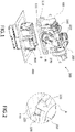
Figure 1 shows a perspective view of the different components of an electrical connector according to embodiments of the present disclosure; -
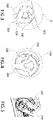
Figure 2 is a close-up view of a section of the lever at the location of the blocking element showing the interaction between the blocking element of the lever and a blocking surface of the first connector when the lever is in the pre-lock position according to embodiments of the present disclosure; -
Figure 3 is a close-up view of a section of the locking mating member of the second connector housing according to embodiments of the present disclosure; -
Figure 4 shows a cross-sectional view of a section of the lever locking mechanism along lines C-C inFigure 1 , according to embodiments of the present disclosure; -
Figure 5 shows a close-up view at the location where the lever arm is releasably secured on the first connector housing according to embodiments of the present disclosure; -
Figure 6 shows an electrical connector with the first and second connector housings in the pre-mated state according to embodiments of the present disclosure; -
Figure 7 shows a close-up cross-sectional view of the first and second connector housings being engaged at the pre-mated state according to embodiments of the present disclosure; -
Figure 8 is a cross-sectional view along lines D-D at the location of the engagement element of the lever locking mechanism according to embodiments of the present disclosure; -
Figure 9 is a cross-sectional view along line E-E at the location of the lever locking mechanism showing the lever being displaced by the activation member of the locking mating member of the second connector housing when the first and second connector housings are in the pre-mated state; -
Figure 10 shows a close-up of the lever blocking member being released from the blocking surface of the first connector housing as a result of the first and second connector housings being in the pre-mated state according to embodiments of the present disclosure; -
Figure 11 shows an electrical connector with the lever in the locked position and the first and second housings secure in the mated state; -
Figure 12 shows a cross-sectional view of the lever locking mechanism being in contact with the corresponding locking mating member of the second connector housing to secure the first and second connector housings in the mated state; -
Figure 13 shows a cross-sectional view of the electrical connector comprising an integrally formed single sealing member according to an embodiment of the present disclosure, a portion of the lever seal of the arrangement ofFigure 13 is shown in an enlarged view; and -
Figure 14 shows a cross-sectional view of the electrical connector comprising a lever seal and a separate panel seal, according to an embodiment of the present disclosure. - The following discussion provides many exemplary embodiments of the inventive subject matter. Although each embodiment represents a single combination of inventive elements, the inventive subject matter is considered to include all possible combinations of the disclosed elements. Thus, if one embodiment comprises elements A, B, and C, and a second embodiment comprises elements B and D, then the inventive subject matter is also considered to include other remaining combinations of A, B, C, or D, even if not explicitly disclosed.
- For simplicity and clarity of illustration, reference numerals may be repeated among the figures to indicate corresponding or analogous elements. Numerous details are set forth to provide an understanding of the examples described herein. The examples may be practised without these details. In other instances, well-known methods, procedures, and components are not described in detail to avoid obscuring the examples described. The description is not to be considered as limited to the scope of the examples described herein.
- Referring now to
Figures 1 to 5 , anelectrical connector 500 may be provided according to embodiments of the present disclosure. As shown inFigure 1 , theelectrical connector 500 comprises afirst connector housing 100, asecond connector housing 300, and a mate assist mechanism comprising alever 200. The first andsecond connector housings first connector housing 100 may be a female connector housing configured to engage with thesecond connector housing 300 being a male connector housing. In particular, and referring toFigure 1 , thesecond connector housing 300 being a male connector housing may be configured to fit inside thefirst connector housing 100 being a female connector housing. Thefirst connector housing 100 is provided with apanel seal 110 configured to seal acontact edge 111 of thefirst connector housing 100 with a panel. The panel may be ametal panel 400 of an automotive vehicle. Thepanel seal 110 may be formed on a recess around the opening of thefirst connector housing 100 using a 2K injection moulding process. It should be noted that a pre-moulded sealing member may be equally used and manually mounted on the opening of thefirst connector housing 100. Thepanel seal 110 is configured, upon coupling of the first andsecond connector housings electrical connector 500. The mate assist mechanism is configured to couple and uncouple the first andsecond connector housings lever 200 between a pre-lock position and a locked position. The pivoting of thelever 200 to the locked position causes the first andsecond connector housings second connector housings lever 200 is pivoted in the opposite direction. Thelever 200 may be provided with twolever arms 210, each pivotably mounted on correspondingopenings 140 in thefirst connector housing 100. Theopenings 140 are configured for accommodating thelever arms 210. For example, holding means may be provided for releasably securing thelever arms 210 on the correspondingopenings 140 on thefirst connector housing 100. As shown inFigure 5 , the holding means may be in the form of alatching mechanism 270 comprising an engagement element, which may be provided on thelever arm 210, configured to cooperate with acorresponding catch 130, which may be provided on thefirst connector housing 100. For example, thecatch 130 may be in the form of a recess provided around a section of the opening in thefirst connector housing 100 configured to cooperate with thelatching mechanism 270 of thelever arm 210. The holding means ensures that thelever arm 200 does not unintentionally disengage from thefirst connector housing 100 upon pivoting of thelever 200 between the pre-lock and locked positions. Thelever 200 is provided with a blockingmember 220, which is configured to cooperate, when the first andsecond housings second connector housing 300 is absent, with a blockingsurface 120 of thefirst connector housing 100. For example, as shown inFigure 2 , the blockingsurface 120 may be provided along the lever rotating path, thereby preventing thelever 200 from moving from the pre-lock position to the locked position. Thesecond connector housing 300 is provided with a lockingmating member 310, which is shown inFigure 3 . The lockingmating member 310 comprises amating surface 340 configured to cooperate, when thelever 200 is moved to the locked position, with a lockingmember 260 of thelever locking mechanism 230 to secure the first andsecond connector housings mating surface 340 of the lockingmating member 310 may be in the form of an opening, recess, or another element of similar functionality that is configured to cooperate with the lockingmember 260 of thelever locking mechanism 230. The lockingmember 260 may be in the form of a gear mechanism comprising at least one gear tooth, as shown inFigure 4 . The lockingmating member 310 may also be provided with a receivingmember 320, which may be in the form of a cavity, or a recess, which is configured to receive when the first andsecond connector housings engagement element 250 of thelever locking mechanism 230, thereby releasably securing the first andsecond connector housings engagement element 250 may be in the form of a protruding member, as shown inFigure 4 . The lockingmating member 310 may be further provided with anactivation element 330 configured to cooperate, when the first andsecond connector housings activation member 240 of thelever locking mechanism 230. For example, theactivation element 330 may be formed as part of a wall of the receivingmember 320 and may be provided with a slanted surface. The correspondingactivation member 240 may be part of the gear mechanism of thelever locking mechanism 230, as shown inFigure 4 . Similarly, theactivation member 240 may be provided with a slanted surface. The slanted surface is configured in an exemplary arrangement such that the lever is deflected by the second connector housing to release the lever locking mechanism. - Turning now to
Figures 6 to 10 , the configuration of theelectrical connector 500 with the first andsecond connector housings Figure 6 . To position the first andsecond connector housings first connector housing 100 is pushed into thesecond connector housing 300 in a male-female connection until an audible sound is generated, indicating that theengagement element 250 of thelever locking mechanism 230 is in engagement with the receivingelement 320 of the lockingmating member 310, as shown inFigures 7 and 8 . At the pre-mated state, theactivation member 330 is configured to be in contact with the correspondingactivation member 240 of thelever locking mechanism 230. As such, theactivation element 330 generates a biasing force on theactivation member 240, causing thelever arm 210 to be displaced outwardly from thefirst connector housing 100. As shown inFigure 9 , thelever arm 210 moves outwardly from thecorresponding opening 140 in thefirst connector housing 100, in the direction of the arrow, without compromising the integrity of alever seal 150 provided around theopening 140 of thefirst connector housing 100. The displacement causes the blockingelement 220 of thelever 200 to be released from the blockingsurface 120 of thefirst connector housing 100 and thelever 200 becomes free to move from the pre-lock position to the locked position as shown inFigure 10 . -
Figures 11 and 12 show theelectrical connector 500 with thelever 200 in the locked position and the first andsecond connector housings Figure 11 , in the mated state, thepanel seal 110 is configured to be in contact with themetal panel 400 of the automotive vehicle thereby providing a watertight connection between thecontact edge 111 of thefirst connector housing 100 and themetal panel 400. Furthermore, with the provision of thelever seal 150 of the holding means, a watertight connection is established between thefirst connector housing 100 and thelever arms 210. As such, a sealedelectrical connector 500 is provided according to embodiments of the present disclosure. As shown inFigures 13 and14 , in the mated state, thesecond connector housing 300 may be configured to fit inside thefirst connector housing 100. In this configuration, thefirst connector housing 100 is disposed between thesecond connector housing 300 and thelever 200. As described above, thefirst connector housing 100 comprises thelever seal 150 for sealing theopening 140 between thefirst connector housing 100 and thelever 200 and thepanel seal 110 for sealing an opening between thefirst connector housing 100 and thepanel 400. As such, a watertight connection is established between thefirst connector housing 100 and thelever arms 210 and between thefirst connector housing 100 and thesecond connector housing 300. Referring toFigure 13 , thelever seal 150 and thepanel seal 110 may be an integrally formedsingle sealing member 151. Alternatively, referring toFigure 14 , thelever seal 150 and thepanel seal 110 may be two separate and discrete sealing members. As shown inFigure 12 , upon positioning thelever 200 in the locked position, thelever locking mechanism 230 cooperates with the lockingmating member 310 to secure the first andsecond connector housings gear tooth 260 of thelever locking mechanism 230 engages with themating surface 340 of the lockingmating mechanism 310, thereby securing the first and second connector housings in the mated state. Pivoting of thelever 200 from the pre-lock position to the lock position causes the disengagement of theengagement element 250 from the receivingelement 320. The assembly of theelectrical connector 500 may be reversed by pivoting of thelever 200 from the locked position to the pre-lock position, which causes the first andsecond connector housings - In the connector assembly of the present disclosure, the displacement of the lever occurs along the complete surface of the lever which is located in contact with
lever seal 150 inside thefirst connector housing 100, and thus the sealing function will not be affected during the release of the lever lock. - As illustrated in the exemplary arrangement of
Figures 9 ,13 and14 , portions of thelever arms 210 are located in theopening 140 surrounded by and in contact with the lever seal within the first connector housing. By virtue of this configuration, the sealing function between the lever, the lever seal and the first connector housing is not affected during the release of the lever lock or displacement of the level within theopening 140. - Effectively, the
lever 200 is located within theopening 140 offirst connector housing 100 such that aperipheral surface 211 of thelever arm 210, is proximate to thelever seal 150, for engagement with the lever seal. In the exemplary arrangement ofFigures 13 and14 , theperipheral surface 211 of thelever arm 210 within the first connector housing has a generally cylindrical or annular form. A first portion of thesurface 211 of the lever arm contacts thelever seal 150. Thelever seal 150 andsurface 211 overlap and contact over a contact length L and a longitudinally extending contact area. The sealing function is provided over a contact length L and has an elongated form. When the lever is displaced, for example outwardly relative to the opening 140 (as described with reference toFigure 9 ) contact between theseal 150 and thesurface 211 of the lever is maintained. Thelever seal 150 comprises a resilient seal configured to maintain a sealing function and to accommodate the displacement of the lever surface relative thereto. In one exemplary arrangement as illustrated inFigure 9 , the seal comprises a plurality ofribs 152 that extend outwardly from a body of the seal to contact thesurface 211. Theseal 150 comprisestrough 153 betweenribs 152. - Accordingly, as described above, the
lever seal 150, is located at least partially between thefirst connector housing 100 and thelever 210 and acts to provide a seal between these components. Thelever seal 150 seals theopening 140 between the first connector housing and the lever. Thelever seal 150 advantageously provides and maintains a continuous seal between the lever and the first connector housing. The sealing function is active also as the components (lever and housing) are moved relative to each other. Accordingly, the lever is sealingly coupled to thefirst connector housing 100. - Advantageously the arrangement of the specification provides for a lever seal, that is located between the lever and first connector housing and a panel seal located between the first connector housing and the panel. The seal is not limited to an arrangement between the first connector housing and the second connector housing. The arrangement of the specification provides for deflection of the lever along the entire surface of the lever located within the lever seal and within the first connector housing, this arrangement advantageously provides a sealing function that is not affected during the release of lever lock or during activation.
- While the present disclosure has been described in terms of the preferred embodiments thereof, it is not intended to be so limited, but rather only to the extent set forth in the claims that follow.
Claims (15)
- An electrical connector (500) comprising,a first connector housing (100) and a second connector housing (300) configured to be coupled to one another through an opening of a panel (400), wherein the second connector housing (300) is configured to fit inside the first connector housing (100); anda mate assist mechanism comprising a lever (200) pivotably and sealingly mounted to the outside of the first connector housing (100), wherein the mate assist mechanism is configured to couple and uncouple the first and second connector housings (100, 300) by pivoting of the lever (200) between a pre-lock position and a locked position;the lever (200) comprisinga locking mechanism (230) configured, upon pivoting the lever (200) to the locked position, to engage with a corresponding locking mating member (310) of the second connector housing (300) to secure the first and second connector housings (100, 300) in a mated state, anda blocking element (220) configured to cooperate when the first and second housings (100,300) are in an uncoupled state or the second connector housing (300) is absent, with a blocking surface (120) of the first connector housing (100) to maintain the lever (200) in the pre-lock position;wherein the locking mating member (310) of the second connector housing (300) comprises an activation element (330) configured to cooperate, when the first and second connector housings (100, 300) are in a pre-mated state, with a corresponding activation member (240) on the locking mechanism (230) of the lever (200), the activation element (330) is configured to exert a biasing force on the corresponding activation member (240) of the locking mechanism (230) causing the lever (200) to be displaced outwardly from the first connector housing (100) such that the blocking element (220) of the lever (200) is released from the blocking surface (120) of the first connector housing (100) and the lever (200) becomes free to move to the locked position,and wherein the first connector housing (100) comprises a lever seal (150) for sealing an opening (140) between the first connector housing (100) and the lever (200) for accommodating the lever (200), and a panel seal (110) for sealing an opening between the first connector housing (100) and the panel (400).
- The electrical connector (500) of claim 1, wherein the activation element (330) is in the form of a protruding surface.
- The electrical connector (500) of claim 1 or 2, wherein the activation element (330) has a slanted surface configured to come in contact with a corresponding activation surface of the corresponding activation member (240) on the locking mechanism (230) of the lever (200).
- The electrical connector (500) of any one of the preceding claims, wherein the locking mechanism (230) of the lever (200) comprises an engagement element (250) configured to engage, when the lever (200) is in the pre-lock position, with a corresponding receiving element (320) on the locking mating member (310) of the second connector housing (300) to releasably secure the first and second connector housings (100, 300) in the pre-mated state.
- The electrical connector (500) of claim 4, wherein upon pivoting the lever (200) to the locked position, the engagement element (250) is configured to be released from the receiving element (320).
- The electrical connector (500) of claim 4 or 5, wherein the receiving element (320) is in the form of a cavity configured to receive the engagement element (250).
- The electrical connector of claim 6, wherein the activation element (330) of the locking mating member (310) of the second connector housing (300) forms one of the walls of the cavity.
- The electrical connector (500) of any one of claims 4 to 7, wherein upon positioning the first and second connector housings (100, 300) in the pre-mated state, an audible sound is generated.
- The electrical connector (500) of any one of the preceding claims, wherein the lever (200) is U-shaped and comprises first and second lever arms (210).
- The electrical connector (500) of claim 9, wherein the first connector housing (100) comprises holding means on opposing sides for releasably securing the first and second lever arms (210).
- The electrical connector (500) of claim 10, wherein the holding means comprise the lever seal (150).
- The electrical connector (500) of any one of claims 9 to 11 wherein each of the first and second lever arms (210) comprises a locking mechanism (230) configured to engage, upon pivoting the lever (200) to the locked position, with corresponding locking mating members (310) of the second connector housing (300).
- The electrical connector (500) of any preceding claim, wherein the lever seal (150) and the panel seal (110) are integrally formed as a single sealing member (151).
- The electrical connector (500) of claim 13, wherein the electrical connector (500) is a door to body connector for an automotive vehicle.
- A method of assembling an electrical connector (500) according to any one of claims 1 to 14, the method comprising the steps of:providing first and second connector housings (100, 300);mounting a lever (200) on the first connector housing (100) such that a blocking element (220) of the lever (200) cooperates with a blocking surface (120) of the first connector housing (100) to maintain the lever (200) in a pre-lock position;biasing the second connector housing (300) to the first connector housing (100) until an audible sound is generated, indicating that the first and second connector housings (100, 300) are in a pre-mated state and the blocking element (220) of the lever (200) is released from the blocking surface (120) of the first connector housing (100); andpivoting the lever (200) from a pre-lock position to a locked position to secure the first and second connector housings (100, 300) in a mated state.
Applications Claiming Priority (1)
| Application Number | Priority Date | Filing Date | Title |
|---|---|---|---|
| GB2018304.2A GB2601164A (en) | 2020-11-20 | 2020-11-20 | Electrical Connector With A Lever Pre-Locking Member And Connector Release Mechanism At Pre-Mating |
Publications (2)
| Publication Number | Publication Date |
|---|---|
| EP4002603A1 true EP4002603A1 (en) | 2022-05-25 |
| EP4002603B1 EP4002603B1 (en) | 2023-07-26 |
Family
ID=74046922
Family Applications (1)
| Application Number | Title | Priority Date | Filing Date |
|---|---|---|---|
| EP21209222.5A Active EP4002603B1 (en) | 2020-11-20 | 2021-11-19 | Electrical connector with a lever locking member and mate assist mechanism |
Country Status (4)
| Country | Link |
|---|---|
| US (1) | US11799240B2 (en) |
| EP (1) | EP4002603B1 (en) |
| CN (1) | CN114520437B (en) |
| GB (1) | GB2601164A (en) |
Families Citing this family (2)
| Publication number | Priority date | Publication date | Assignee | Title |
|---|---|---|---|---|
| DE102020132994A1 (en) * | 2020-12-10 | 2022-06-15 | Te Connectivity Germany Gmbh | Electrical plug-in device with a locking mechanism, which can be released by a counter-housing, for a position-securing element |
| DE102023117242A1 (en) * | 2023-06-29 | 2025-01-02 | Lisa Dräxlmaier GmbH | PLUG-IN SYSTEM WITH LOCKING ELEMENT AND RELEASE ELEMENT |
Citations (7)
| Publication number | Priority date | Publication date | Assignee | Title |
|---|---|---|---|---|
| EP1077512A2 (en) * | 1999-08-17 | 2001-02-21 | Framatome Connectors International | Electrical plug connector |
| US20070197074A1 (en) * | 2004-04-07 | 2007-08-23 | Markus Gimbel | Sealed Plug Connection Through a Partition Wall And Method Of Fitting |
| EP2454785A1 (en) | 2009-07-13 | 2012-05-23 | Tyco Electronics AMP GmbH | Plug-and-socket connector with a blocking element |
| JP2013182874A (en) * | 2012-03-05 | 2013-09-12 | Sumitomo Wiring Syst Ltd | Lever type connector |
| US20140273565A1 (en) * | 2011-10-26 | 2014-09-18 | Delphi Technologies, Inc. | Two-part electrical plug connector |
| EP3392979A1 (en) * | 2017-04-19 | 2018-10-24 | Delphi Technologies, Inc. | Electrical connector with lever |
| US20190123485A1 (en) * | 2017-10-20 | 2019-04-25 | Lear Corporation | Electrical Connector with Assist Lever |
Family Cites Families (14)
| Publication number | Priority date | Publication date | Assignee | Title |
|---|---|---|---|---|
| US5709560A (en) * | 1994-12-14 | 1998-01-20 | Sumitomo Wiring Systems, Ltd. | Connector having a pivotable connection-assistance member |
| JP4229282B2 (en) * | 2004-04-28 | 2009-02-25 | タイコエレクトロニクスアンプ株式会社 | Lever type connector |
| US7361036B2 (en) * | 2005-10-06 | 2008-04-22 | Fci Americas Technology, Inc. | Electrical connector with lever and latch |
| US7267564B2 (en) * | 2005-12-01 | 2007-09-11 | Molex Incorporated | Lever type electrical connector |
| CN103688421B (en) * | 2011-07-20 | 2016-02-10 | 德尔福国际业务卢森堡公司 | Electric coupler component |
| JP5929829B2 (en) * | 2013-05-21 | 2016-06-08 | 住友電装株式会社 | Lever type connector |
| EP2863489A1 (en) | 2013-10-16 | 2015-04-22 | Delphi Technologies, Inc. | Connector assembly with integrated lever locking system |
| JP6572188B2 (en) * | 2016-09-07 | 2019-09-04 | 矢崎総業株式会社 | Lever type connector |
| JP6564750B2 (en) * | 2016-09-07 | 2019-08-21 | 矢崎総業株式会社 | Lever type connector |
| EP3322041B1 (en) * | 2016-11-09 | 2019-10-30 | Aptiv Technologies Limited | Connector assembly with integrated lever locking system |
| US10270207B1 (en) * | 2017-10-20 | 2019-04-23 | Lear Corporation | Electrical connector with assist lever |
| US10135183B1 (en) * | 2017-10-20 | 2018-11-20 | Lear Corporation | Electrical connector with assist lever |
| US10270208B1 (en) * | 2017-10-20 | 2019-04-23 | Lear Corporation | Electrical connector with assist lever |
| US10218117B1 (en) * | 2017-10-20 | 2019-02-26 | Lear Corporation | Electrical connector with assist lever |
-
2020
- 2020-11-20 GB GB2018304.2A patent/GB2601164A/en not_active Withdrawn
-
2021
- 2021-11-18 US US17/529,528 patent/US11799240B2/en active Active
- 2021-11-19 EP EP21209222.5A patent/EP4002603B1/en active Active
- 2021-11-19 CN CN202111375218.1A patent/CN114520437B/en active Active
Patent Citations (8)
| Publication number | Priority date | Publication date | Assignee | Title |
|---|---|---|---|---|
| EP1077512A2 (en) * | 1999-08-17 | 2001-02-21 | Framatome Connectors International | Electrical plug connector |
| US20070197074A1 (en) * | 2004-04-07 | 2007-08-23 | Markus Gimbel | Sealed Plug Connection Through a Partition Wall And Method Of Fitting |
| EP2454785A1 (en) | 2009-07-13 | 2012-05-23 | Tyco Electronics AMP GmbH | Plug-and-socket connector with a blocking element |
| US20140273565A1 (en) * | 2011-10-26 | 2014-09-18 | Delphi Technologies, Inc. | Two-part electrical plug connector |
| US9178307B2 (en) | 2011-10-26 | 2015-11-03 | Delphi Technologies, Inc. | Connector having a housing with a first tooth system actuated by a second tooth system on a lever |
| JP2013182874A (en) * | 2012-03-05 | 2013-09-12 | Sumitomo Wiring Syst Ltd | Lever type connector |
| EP3392979A1 (en) * | 2017-04-19 | 2018-10-24 | Delphi Technologies, Inc. | Electrical connector with lever |
| US20190123485A1 (en) * | 2017-10-20 | 2019-04-25 | Lear Corporation | Electrical Connector with Assist Lever |
Also Published As
| Publication number | Publication date |
|---|---|
| US20220166165A1 (en) | 2022-05-26 |
| GB202018304D0 (en) | 2021-01-06 |
| EP4002603B1 (en) | 2023-07-26 |
| CN114520437B (en) | 2024-08-09 |
| GB2601164A (en) | 2022-05-25 |
| US11799240B2 (en) | 2023-10-24 |
| CN114520437A (en) | 2022-05-20 |
Similar Documents
| Publication | Publication Date | Title |
|---|---|---|
| CN216648736U (en) | Connector assembly | |
| JP2605189B2 (en) | Connector connection device | |
| US6368125B1 (en) | Connector with lever | |
| US5681184A (en) | Connector with secondary locking and coupling mechanisms | |
| CN106463889B (en) | Connector Positioning Assemblies (CPAs) and Mating Connector Assemblies with CPAs | |
| JP4317973B2 (en) | connector | |
| KR100875066B1 (en) | Lever type electrical connector with slide member with double latching and feedback function | |
| KR102459124B1 (en) | Electrical connector with lever | |
| CA2276770C (en) | Connector with lever | |
| JP6647739B2 (en) | Assembly structure of connector and connector cover | |
| US7198496B2 (en) | Lever type connector | |
| EP4002603B1 (en) | Electrical connector with a lever locking member and mate assist mechanism | |
| CN111834836B (en) | Connector with grommet | |
| CN114665326A (en) | First connector, second connector and connector combination | |
| US6142826A (en) | Sealed electrical connector with secondary locking member | |
| JP2000173709A (en) | Waterproof connector | |
| JP2018067378A (en) | connector | |
| JP5136363B2 (en) | Lever type connector | |
| JP7145953B2 (en) | lever type connector | |
| EP4125154A1 (en) | Connector | |
| JP4158912B2 (en) | Lever type mating connector for panel mounting | |
| JP3548325B2 (en) | Connector connection structure and unit connection structure | |
| EP0942491A2 (en) | Sealed electrical connector with secondary locking member | |
| WO2021161763A1 (en) | Lever-type connector |
Legal Events
| Date | Code | Title | Description |
|---|---|---|---|
| PUAI | Public reference made under article 153(3) epc to a published international application that has entered the european phase |
Free format text: ORIGINAL CODE: 0009012 |
|
| STAA | Information on the status of an ep patent application or granted ep patent |
Free format text: STATUS: THE APPLICATION HAS BEEN PUBLISHED |
|
| AK | Designated contracting states |
Kind code of ref document: A1 Designated state(s): AL AT BE BG CH CY CZ DE DK EE ES FI FR GB GR HR HU IE IS IT LI LT LU LV MC MK MT NL NO PL PT RO RS SE SI SK SM TR |
|
| STAA | Information on the status of an ep patent application or granted ep patent |
Free format text: STATUS: REQUEST FOR EXAMINATION WAS MADE |
|
| 17P | Request for examination filed |
Effective date: 20220930 |
|
| RBV | Designated contracting states (corrected) |
Designated state(s): AL AT BE BG CH CY CZ DE DK EE ES FI FR GB GR HR HU IE IS IT LI LT LU LV MC MK MT NL NO PL PT RO RS SE SI SK SM TR |
|
| REG | Reference to a national code |
Ref country code: DE Free format text: PREVIOUS MAIN CLASS: H01R0013629000 Ref country code: DE Ref legal event code: R079 Ref document number: 602021003794 Country of ref document: DE Free format text: PREVIOUS MAIN CLASS: H01R0013629000 Ipc: H01R0013520000 |
|
| GRAP | Despatch of communication of intention to grant a patent |
Free format text: ORIGINAL CODE: EPIDOSNIGR1 |
|
| STAA | Information on the status of an ep patent application or granted ep patent |
Free format text: STATUS: GRANT OF PATENT IS INTENDED |
|
| RIC1 | Information provided on ipc code assigned before grant |
Ipc: H01R 13/74 20060101ALN20230131BHEP Ipc: H01R 13/629 20060101ALI20230131BHEP Ipc: H01R 13/52 20060101AFI20230131BHEP |
|
| INTG | Intention to grant announced |
Effective date: 20230213 |
|
| GRAS | Grant fee paid |
Free format text: ORIGINAL CODE: EPIDOSNIGR3 |
|
| GRAA | (expected) grant |
Free format text: ORIGINAL CODE: 0009210 |
|
| STAA | Information on the status of an ep patent application or granted ep patent |
Free format text: STATUS: THE PATENT HAS BEEN GRANTED |
|
| P01 | Opt-out of the competence of the unified patent court (upc) registered |
Effective date: 20230613 |
|
| AK | Designated contracting states |
Kind code of ref document: B1 Designated state(s): AL AT BE BG CH CY CZ DE DK EE ES FI FR GB GR HR HU IE IS IT LI LT LU LV MC MK MT NL NO PL PT RO RS SE SI SK SM TR |
|
| REG | Reference to a national code |
Ref country code: CH Ref legal event code: EP |
|
| REG | Reference to a national code |
Ref country code: IE Ref legal event code: FG4D |
|
| REG | Reference to a national code |
Ref country code: DE Ref legal event code: R096 Ref document number: 602021003794 Country of ref document: DE |
|
| REG | Reference to a national code |
Ref country code: LT Ref legal event code: MG9D |
|
| REG | Reference to a national code |
Ref country code: NL Ref legal event code: MP Effective date: 20230726 |
|
| REG | Reference to a national code |
Ref country code: AT Ref legal event code: MK05 Ref document number: 1593044 Country of ref document: AT Kind code of ref document: T Effective date: 20230726 |
|
| PG25 | Lapsed in a contracting state [announced via postgrant information from national office to epo] |
Ref country code: NL Free format text: LAPSE BECAUSE OF FAILURE TO SUBMIT A TRANSLATION OF THE DESCRIPTION OR TO PAY THE FEE WITHIN THE PRESCRIBED TIME-LIMIT Effective date: 20230726 |
|
| PG25 | Lapsed in a contracting state [announced via postgrant information from national office to epo] |
Ref country code: GR Free format text: LAPSE BECAUSE OF FAILURE TO SUBMIT A TRANSLATION OF THE DESCRIPTION OR TO PAY THE FEE WITHIN THE PRESCRIBED TIME-LIMIT Effective date: 20231027 |
|
| PG25 | Lapsed in a contracting state [announced via postgrant information from national office to epo] |
Ref country code: IS Free format text: LAPSE BECAUSE OF FAILURE TO SUBMIT A TRANSLATION OF THE DESCRIPTION OR TO PAY THE FEE WITHIN THE PRESCRIBED TIME-LIMIT Effective date: 20231126 |
|
| PG25 | Lapsed in a contracting state [announced via postgrant information from national office to epo] |
Ref country code: SE Free format text: LAPSE BECAUSE OF FAILURE TO SUBMIT A TRANSLATION OF THE DESCRIPTION OR TO PAY THE FEE WITHIN THE PRESCRIBED TIME-LIMIT Effective date: 20230726 Ref country code: RS Free format text: LAPSE BECAUSE OF FAILURE TO SUBMIT A TRANSLATION OF THE DESCRIPTION OR TO PAY THE FEE WITHIN THE PRESCRIBED TIME-LIMIT Effective date: 20230726 Ref country code: PT Free format text: LAPSE BECAUSE OF FAILURE TO SUBMIT A TRANSLATION OF THE DESCRIPTION OR TO PAY THE FEE WITHIN THE PRESCRIBED TIME-LIMIT Effective date: 20231127 Ref country code: NO Free format text: LAPSE BECAUSE OF FAILURE TO SUBMIT A TRANSLATION OF THE DESCRIPTION OR TO PAY THE FEE WITHIN THE PRESCRIBED TIME-LIMIT Effective date: 20231026 Ref country code: LV Free format text: LAPSE BECAUSE OF FAILURE TO SUBMIT A TRANSLATION OF THE DESCRIPTION OR TO PAY THE FEE WITHIN THE PRESCRIBED TIME-LIMIT Effective date: 20230726 Ref country code: LT Free format text: LAPSE BECAUSE OF FAILURE TO SUBMIT A TRANSLATION OF THE DESCRIPTION OR TO PAY THE FEE WITHIN THE PRESCRIBED TIME-LIMIT Effective date: 20230726 Ref country code: IS Free format text: LAPSE BECAUSE OF FAILURE TO SUBMIT A TRANSLATION OF THE DESCRIPTION OR TO PAY THE FEE WITHIN THE PRESCRIBED TIME-LIMIT Effective date: 20231126 Ref country code: HR Free format text: LAPSE BECAUSE OF FAILURE TO SUBMIT A TRANSLATION OF THE DESCRIPTION OR TO PAY THE FEE WITHIN THE PRESCRIBED TIME-LIMIT Effective date: 20230726 Ref country code: GR Free format text: LAPSE BECAUSE OF FAILURE TO SUBMIT A TRANSLATION OF THE DESCRIPTION OR TO PAY THE FEE WITHIN THE PRESCRIBED TIME-LIMIT Effective date: 20231027 Ref country code: FI Free format text: LAPSE BECAUSE OF FAILURE TO SUBMIT A TRANSLATION OF THE DESCRIPTION OR TO PAY THE FEE WITHIN THE PRESCRIBED TIME-LIMIT Effective date: 20230726 Ref country code: AT Free format text: LAPSE BECAUSE OF FAILURE TO SUBMIT A TRANSLATION OF THE DESCRIPTION OR TO PAY THE FEE WITHIN THE PRESCRIBED TIME-LIMIT Effective date: 20230726 |
|
| PG25 | Lapsed in a contracting state [announced via postgrant information from national office to epo] |
Ref country code: PL Free format text: LAPSE BECAUSE OF FAILURE TO SUBMIT A TRANSLATION OF THE DESCRIPTION OR TO PAY THE FEE WITHIN THE PRESCRIBED TIME-LIMIT Effective date: 20230726 |
|
| PG25 | Lapsed in a contracting state [announced via postgrant information from national office to epo] |
Ref country code: ES Free format text: LAPSE BECAUSE OF FAILURE TO SUBMIT A TRANSLATION OF THE DESCRIPTION OR TO PAY THE FEE WITHIN THE PRESCRIBED TIME-LIMIT Effective date: 20230726 |
|
| REG | Reference to a national code |
Ref country code: DE Ref legal event code: R097 Ref document number: 602021003794 Country of ref document: DE |
|
| PG25 | Lapsed in a contracting state [announced via postgrant information from national office to epo] |
Ref country code: SM Free format text: LAPSE BECAUSE OF FAILURE TO SUBMIT A TRANSLATION OF THE DESCRIPTION OR TO PAY THE FEE WITHIN THE PRESCRIBED TIME-LIMIT Effective date: 20230726 Ref country code: RO Free format text: LAPSE BECAUSE OF FAILURE TO SUBMIT A TRANSLATION OF THE DESCRIPTION OR TO PAY THE FEE WITHIN THE PRESCRIBED TIME-LIMIT Effective date: 20230726 Ref country code: ES Free format text: LAPSE BECAUSE OF FAILURE TO SUBMIT A TRANSLATION OF THE DESCRIPTION OR TO PAY THE FEE WITHIN THE PRESCRIBED TIME-LIMIT Effective date: 20230726 Ref country code: EE Free format text: LAPSE BECAUSE OF FAILURE TO SUBMIT A TRANSLATION OF THE DESCRIPTION OR TO PAY THE FEE WITHIN THE PRESCRIBED TIME-LIMIT Effective date: 20230726 Ref country code: DK Free format text: LAPSE BECAUSE OF FAILURE TO SUBMIT A TRANSLATION OF THE DESCRIPTION OR TO PAY THE FEE WITHIN THE PRESCRIBED TIME-LIMIT Effective date: 20230726 Ref country code: CZ Free format text: LAPSE BECAUSE OF FAILURE TO SUBMIT A TRANSLATION OF THE DESCRIPTION OR TO PAY THE FEE WITHIN THE PRESCRIBED TIME-LIMIT Effective date: 20230726 Ref country code: SK Free format text: LAPSE BECAUSE OF FAILURE TO SUBMIT A TRANSLATION OF THE DESCRIPTION OR TO PAY THE FEE WITHIN THE PRESCRIBED TIME-LIMIT Effective date: 20230726 |
|
| PG25 | Lapsed in a contracting state [announced via postgrant information from national office to epo] |
Ref country code: IT Free format text: LAPSE BECAUSE OF FAILURE TO SUBMIT A TRANSLATION OF THE DESCRIPTION OR TO PAY THE FEE WITHIN THE PRESCRIBED TIME-LIMIT Effective date: 20230726 |
|
| PLBE | No opposition filed within time limit |
Free format text: ORIGINAL CODE: 0009261 |
|
| STAA | Information on the status of an ep patent application or granted ep patent |
Free format text: STATUS: NO OPPOSITION FILED WITHIN TIME LIMIT |
|
| PG25 | Lapsed in a contracting state [announced via postgrant information from national office to epo] |
Ref country code: MC Free format text: LAPSE BECAUSE OF FAILURE TO SUBMIT A TRANSLATION OF THE DESCRIPTION OR TO PAY THE FEE WITHIN THE PRESCRIBED TIME-LIMIT Effective date: 20230726 |
|
| 26N | No opposition filed |
Effective date: 20240429 |
|
| PG25 | Lapsed in a contracting state [announced via postgrant information from national office to epo] |
Ref country code: LU Free format text: LAPSE BECAUSE OF NON-PAYMENT OF DUE FEES Effective date: 20231119 |
|
| PG25 | Lapsed in a contracting state [announced via postgrant information from national office to epo] |
Ref country code: MC Free format text: LAPSE BECAUSE OF FAILURE TO SUBMIT A TRANSLATION OF THE DESCRIPTION OR TO PAY THE FEE WITHIN THE PRESCRIBED TIME-LIMIT Effective date: 20230726 Ref country code: LU Free format text: LAPSE BECAUSE OF NON-PAYMENT OF DUE FEES Effective date: 20231119 Ref country code: SI Free format text: LAPSE BECAUSE OF FAILURE TO SUBMIT A TRANSLATION OF THE DESCRIPTION OR TO PAY THE FEE WITHIN THE PRESCRIBED TIME-LIMIT Effective date: 20230726 |
|
| REG | Reference to a national code |
Ref country code: BE Ref legal event code: MM Effective date: 20231130 |
|
| REG | Reference to a national code |
Ref country code: IE Ref legal event code: MM4A |
|
| PG25 | Lapsed in a contracting state [announced via postgrant information from national office to epo] |
Ref country code: IE Free format text: LAPSE BECAUSE OF NON-PAYMENT OF DUE FEES Effective date: 20231119 |
|
| PG25 | Lapsed in a contracting state [announced via postgrant information from national office to epo] |
Ref country code: BE Free format text: LAPSE BECAUSE OF NON-PAYMENT OF DUE FEES Effective date: 20231130 |
|
| PG25 | Lapsed in a contracting state [announced via postgrant information from national office to epo] |
Ref country code: IE Free format text: LAPSE BECAUSE OF NON-PAYMENT OF DUE FEES Effective date: 20231119 Ref country code: BE Free format text: LAPSE BECAUSE OF NON-PAYMENT OF DUE FEES Effective date: 20231130 |
|
| PG25 | Lapsed in a contracting state [announced via postgrant information from national office to epo] |
Ref country code: BG Free format text: LAPSE BECAUSE OF FAILURE TO SUBMIT A TRANSLATION OF THE DESCRIPTION OR TO PAY THE FEE WITHIN THE PRESCRIBED TIME-LIMIT Effective date: 20230726 |
|
| PG25 | Lapsed in a contracting state [announced via postgrant information from national office to epo] |
Ref country code: BG Free format text: LAPSE BECAUSE OF FAILURE TO SUBMIT A TRANSLATION OF THE DESCRIPTION OR TO PAY THE FEE WITHIN THE PRESCRIBED TIME-LIMIT Effective date: 20230726 |
|
| REG | Reference to a national code |
Ref country code: DE Ref legal event code: R081 Ref document number: 602021003794 Country of ref document: DE Owner name: APTIV TECHNOLOGIES AG, CH Free format text: FORMER OWNER: APTIV TECHNOLOGIES LIMITED, ST. MICHAEL, BB |
|
| REG | Reference to a national code |
Ref country code: CH Ref legal event code: PL |
|
| REG | Reference to a national code |
Ref country code: CH Ref legal event code: PL |
|
| PG25 | Lapsed in a contracting state [announced via postgrant information from national office to epo] |
Ref country code: CH Free format text: LAPSE BECAUSE OF NON-PAYMENT OF DUE FEES Effective date: 20241130 |
|
| PG25 | Lapsed in a contracting state [announced via postgrant information from national office to epo] |
Ref country code: CY Free format text: LAPSE BECAUSE OF FAILURE TO SUBMIT A TRANSLATION OF THE DESCRIPTION OR TO PAY THE FEE WITHIN THE PRESCRIBED TIME-LIMIT; INVALID AB INITIO Effective date: 20211119 |
|
| PG25 | Lapsed in a contracting state [announced via postgrant information from national office to epo] |
Ref country code: TR Free format text: LAPSE BECAUSE OF FAILURE TO SUBMIT A TRANSLATION OF THE DESCRIPTION OR TO PAY THE FEE WITHIN THE PRESCRIBED TIME-LIMIT Effective date: 20230726 |
|
| PGFP | Annual fee paid to national office [announced via postgrant information from national office to epo] |
Ref country code: DE Payment date: 20251010 Year of fee payment: 5 |
|
| PGFP | Annual fee paid to national office [announced via postgrant information from national office to epo] |
Ref country code: GB Payment date: 20251107 Year of fee payment: 5 |
|
| PGFP | Annual fee paid to national office [announced via postgrant information from national office to epo] |
Ref country code: FR Payment date: 20251112 Year of fee payment: 5 |
|
| PG25 | Lapsed in a contracting state [announced via postgrant information from national office to epo] |
Ref country code: HU Free format text: LAPSE BECAUSE OF FAILURE TO SUBMIT A TRANSLATION OF THE DESCRIPTION OR TO PAY THE FEE WITHIN THE PRESCRIBED TIME-LIMIT; INVALID AB INITIO Effective date: 20211119 |
|
| REG | Reference to a national code |
Ref country code: GB Ref legal event code: 732E Free format text: REGISTERED BETWEEN 20260507 AND 20260513 |
|
| PG25 | Lapsed in a contracting state [announced via postgrant information from national office to epo] |
Ref country code: CH Free format text: THE PATENT HAS BEEN ANNULLED BY A DECISION OF A NATIONAL AUTHORITY Effective date: 20241130 |
|
| REG | Reference to a national code |
Ref country code: GB Ref legal event code: 732E Free format text: REGISTERED BETWEEN 20260521 AND 20260527 |
|
| PG25 | Lapsed in a contracting state [announced via postgrant information from national office to epo] |
Ref country code: MT Free format text: LAPSE BECAUSE OF NON-PAYMENT OF DUE FEES Effective date: 20231119 |