EP4002586A1 - Esa quadrant mechanical reconfiguration - Google Patents
Esa quadrant mechanical reconfiguration Download PDFInfo
- Publication number
- EP4002586A1 EP4002586A1 EP21209612.7A EP21209612A EP4002586A1 EP 4002586 A1 EP4002586 A1 EP 4002586A1 EP 21209612 A EP21209612 A EP 21209612A EP 4002586 A1 EP4002586 A1 EP 4002586A1
- Authority
- EP
- European Patent Office
- Prior art keywords
- esa
- rotational
- panel
- panels
- azimuthal position
- Prior art date
- Legal status (The legal status is an assumption and is not a legal conclusion. Google has not performed a legal analysis and makes no representation as to the accuracy of the status listed.)
- Granted
Links
Images





Classifications
-
- H—ELECTRICITY
- H01—ELECTRIC ELEMENTS
- H01Q—ANTENNAS, i.e. RADIO AERIALS
- H01Q3/00—Arrangements for changing or varying the orientation or the shape of the directional pattern of the waves radiated from an antenna or antenna system
- H01Q3/02—Arrangements for changing or varying the orientation or the shape of the directional pattern of the waves radiated from an antenna or antenna system using mechanical movement of antenna or antenna system as a whole
- H01Q3/04—Arrangements for changing or varying the orientation or the shape of the directional pattern of the waves radiated from an antenna or antenna system using mechanical movement of antenna or antenna system as a whole for varying one co-ordinate of the orientation
- H01Q3/06—Arrangements for changing or varying the orientation or the shape of the directional pattern of the waves radiated from an antenna or antenna system using mechanical movement of antenna or antenna system as a whole for varying one co-ordinate of the orientation over a restricted angle
-
- G—PHYSICS
- G01—MEASURING; TESTING
- G01S—RADIO DIRECTION-FINDING; RADIO NAVIGATION; DETERMINING DISTANCE OR VELOCITY BY USE OF RADIO WAVES; LOCATING OR PRESENCE-DETECTING BY USE OF THE REFLECTION OR RERADIATION OF RADIO WAVES; ANALOGOUS ARRANGEMENTS USING OTHER WAVES
- G01S13/00—Systems using the reflection or reradiation of radio waves, e.g. radar systems; Analogous systems using reflection or reradiation of waves whose nature or wavelength is irrelevant or unspecified
- G01S13/66—Radar-tracking systems; Analogous systems
-
- G—PHYSICS
- G01—MEASURING; TESTING
- G01S—RADIO DIRECTION-FINDING; RADIO NAVIGATION; DETERMINING DISTANCE OR VELOCITY BY USE OF RADIO WAVES; LOCATING OR PRESENCE-DETECTING BY USE OF THE REFLECTION OR RERADIATION OF RADIO WAVES; ANALOGOUS ARRANGEMENTS USING OTHER WAVES
- G01S7/00—Details of systems according to groups G01S13/00, G01S15/00, G01S17/00
- G01S7/02—Details of systems according to groups G01S13/00, G01S15/00, G01S17/00 of systems according to group G01S13/00
- G01S7/40—Means for monitoring or calibrating
- G01S7/4004—Means for monitoring or calibrating of parts of a radar system
- G01S7/4026—Antenna boresight
-
- H—ELECTRICITY
- H01—ELECTRIC ELEMENTS
- H01Q—ANTENNAS, i.e. RADIO AERIALS
- H01Q1/00—Details of, or arrangements associated with, antennas
- H01Q1/27—Adaptation for use in or on movable bodies
- H01Q1/28—Adaptation for use in or on aircraft, missiles, satellites, or balloons
- H01Q1/281—Nose antennas
-
- H—ELECTRICITY
- H01—ELECTRIC ELEMENTS
- H01Q—ANTENNAS, i.e. RADIO AERIALS
- H01Q1/00—Details of, or arrangements associated with, antennas
- H01Q1/27—Adaptation for use in or on movable bodies
- H01Q1/28—Adaptation for use in or on aircraft, missiles, satellites, or balloons
- H01Q1/282—Modifying the aerodynamic properties of the vehicle, e.g. projecting type aerials
-
- H—ELECTRICITY
- H01—ELECTRIC ELEMENTS
- H01Q—ANTENNAS, i.e. RADIO AERIALS
- H01Q3/00—Arrangements for changing or varying the orientation or the shape of the directional pattern of the waves radiated from an antenna or antenna system
- H01Q3/12—Arrangements for changing or varying the orientation or the shape of the directional pattern of the waves radiated from an antenna or antenna system using mechanical relative movement between primary active elements and secondary devices of antennas or antenna systems
-
- H—ELECTRICITY
- H01—ELECTRIC ELEMENTS
- H01Q—ANTENNAS, i.e. RADIO AERIALS
- H01Q3/00—Arrangements for changing or varying the orientation or the shape of the directional pattern of the waves radiated from an antenna or antenna system
- H01Q3/26—Arrangements for changing or varying the orientation or the shape of the directional pattern of the waves radiated from an antenna or antenna system varying the relative phase or relative amplitude of energisation between two or more active radiating elements; varying the distribution of energy across a radiating aperture
-
- H—ELECTRICITY
- H01—ELECTRIC ELEMENTS
- H01Q—ANTENNAS, i.e. RADIO AERIALS
- H01Q3/00—Arrangements for changing or varying the orientation or the shape of the directional pattern of the waves radiated from an antenna or antenna system
- H01Q3/26—Arrangements for changing or varying the orientation or the shape of the directional pattern of the waves radiated from an antenna or antenna system varying the relative phase or relative amplitude of energisation between two or more active radiating elements; varying the distribution of energy across a radiating aperture
- H01Q3/2664—Arrangements for changing or varying the orientation or the shape of the directional pattern of the waves radiated from an antenna or antenna system varying the relative phase or relative amplitude of energisation between two or more active radiating elements; varying the distribution of energy across a radiating aperture electrically moving the phase centre of a radiating element in the focal plane of a focussing device
-
- G—PHYSICS
- G01—MEASURING; TESTING
- G01S—RADIO DIRECTION-FINDING; RADIO NAVIGATION; DETERMINING DISTANCE OR VELOCITY BY USE OF RADIO WAVES; LOCATING OR PRESENCE-DETECTING BY USE OF THE REFLECTION OR RERADIATION OF RADIO WAVES; ANALOGOUS ARRANGEMENTS USING OTHER WAVES
- G01S13/00—Systems using the reflection or reradiation of radio waves, e.g. radar systems; Analogous systems using reflection or reradiation of waves whose nature or wavelength is irrelevant or unspecified
- G01S13/02—Systems using reflection of radio waves, e.g. primary radar systems; Analogous systems
- G01S2013/0236—Special technical features
- G01S2013/0245—Radar with phased array antenna
-
- G—PHYSICS
- G01—MEASURING; TESTING
- G01S—RADIO DIRECTION-FINDING; RADIO NAVIGATION; DETERMINING DISTANCE OR VELOCITY BY USE OF RADIO WAVES; LOCATING OR PRESENCE-DETECTING BY USE OF THE REFLECTION OR RERADIATION OF RADIO WAVES; ANALOGOUS ARRANGEMENTS USING OTHER WAVES
- G01S13/00—Systems using the reflection or reradiation of radio waves, e.g. radar systems; Analogous systems using reflection or reradiation of waves whose nature or wavelength is irrelevant or unspecified
- G01S13/02—Systems using reflection of radio waves, e.g. primary radar systems; Analogous systems
- G01S2013/0236—Special technical features
- G01S2013/0245—Radar with phased array antenna
- G01S2013/0254—Active array antenna
Definitions
- Beamforming may be complex on angled, multi panel electronically scanned array (ESA) surfaces requiring signal delays as well as return signal integration across varying sets of quadrants. These multi panel ESA configurations may be considerably expensive compared to the supporting hardware and mechanical fixtures. In an angled multi panel design, an apparent aperture size may reduce as the directed beam moves away from boresight which results in lower gain, lower range and increased interference.
- ESA electronically scanned array
- a system for mechanically positioning an electronically scanned array (ESA) panel may comprise two or more rotational ESA panels onboard an aircraft, the two rotational ESA panels configured for a rotation, the rotation about a vertical axis.
- each of the two rotational ESA panels may be individually operational in a first azimuthal position having a first boresight and collectively operational in a second azimuthal position having a common boresight, the second azimuthal position of each of the two rotational ESA panels being equal, the first azimuthal position distant from the second azimuthal position by the rotation.
- an actuator may be coupled with each of the two rotational ESA panels, the actuator configured to mechanically cause the rotation.
- the system may also include a radar display available to one of a pilot and an autopilot of the aircraft.
- the system may include a controller operatively coupled with each of the two rotational ESA panels and the actuator and a tangible, non-transitory memory configured to communicate with the controller, the tangible, non-transitory memory having instructions stored therein that, in response to execution by the controller, cause the controller to carry out each function of the system.
- the controller may receive a rotation trigger for commanding the actuator to rotate the two rotational ESA panels and command the actuator to rotate the two rotational ESA panels from the first azimuthal position to the second azimuthal position without stopping in an intermediate azimuthal position.
- the controller may further electronically couple the two rotational ESA panels while in the second azimuthal position to coherently operate as a single aggregate ESA having the common boresight and receive a radar signal from the single aggregate ESA having the common boresight.
- the system may display the radar signal on the radar display.
- the controller may receive a de-rotation trigger to rotate the two rotational ESA panels from the second azimuthal position to the first azimuthal position and command the actuator to de-rotate the two rotational ESA panels from the second azimuthal position to the first azimuthal position.
- An additional embodiment of the inventive concepts disclosed herein is directed to a method for mechanically positioning an electronically scanned array (ESA) panel.
- the method may comprise receiving a rotation trigger for commanding an actuator to rotate two rotational ESA panels onboard an aircraft and commanding an actuator to mechanically rotate the two rotational ESA panels about a vertical axis from a first azimuthal position to a second azimuthal position.
- the method may include electronically coupling the two rotational ESA panels while in the second azimuthal position to coherently operate as a single aggregate ESA having a common boresight and receiving a radar signal from the single aggregate ESA having the common boresight.
- the method may further include displaying the radar signal on a radar display onboard the aircraft.
- inventive concepts are not limited in their application to the details of construction and the arrangement of the components or steps or methodologies set forth in the following description or illustrated in the drawings.
- inventive concepts disclosed herein may be practiced without these specific details.
- well-known features may not be described in detail to avoid unnecessarily complicating the instant disclosure.
- inventive concepts disclosed herein are capable of other embodiments or of being practiced or carried out in various ways. Also, it is to be understood that the phraseology and terminology employed herein is for the purpose of description and should not be regarded as limiting.
- a letter following a reference numeral is intended to reference an embodiment of the feature or element that may be similar, but not necessarily identical, to a previously described element or feature bearing the same reference numeral (e.g., 1, 1a, 1b).
- reference numeral e.g. 1, 1a, 1b
- Such shorthand notations are used for purposes of convenience only, and should not be construed to limit the inventive concepts disclosed herein in any way unless expressly stated to the contrary.
- any reference to "one embodiment,” or “some embodiments” means that a particular element, feature, structure, or characteristic described in connection with the embodiment is included in at least one embodiment of the inventive concepts disclosed herein.
- the appearances of the phrase “in some embodiments” in various places in the specification are not necessarily all referring to the same embodiment, and embodiments of the inventive concepts disclosed may include one or more of the features expressly described or inherently present herein, or any combination of sub-combination of two or more such features, along with any other features which may not necessarily be expressly described or inherently present in the instant disclosure.
- inventions of the inventive concepts disclosed herein are directed to a system and method for ESA quadrant mechanical reconfiguration.
- the system functions to shift some of the complexity from algorithmic manipulation of received radar data to mechanical transformation of a simple panel structure to achieve desired performance in a desired ESA boresight.
- the system receives a rotation trigger based on an external event such as altitude and mission and causes two or more simple ESA panels to rotate from a first azimuthal position to a second common azimuthal position without stopping at an intermediate azimuth. Once positioned, each individual rotational ESA panel is combined to function as a single aggregate ESA enabling desired performance in field of view, resolution and range at a common boresight.
- a system for mechanically positioning an electronically scanned array panel may include angularly, mechanically manipulating rotational ESA panels from a first azimuthal position to a second, common azimuthal position. Once rotated, the system may function to electronically couple the two rotational ESA panels while in the second azimuthal position to coherently operate as a single aggregate ESA having a common boresight.
- the system for mechanically positioning an electronically scanned array panel 100 may include at least two rotational ESA panels which may include a left rotational ESA 122 and a right rotational ESA 124.
- the two rotational ESA panels may be in a chevron configuration as shown in FIG. 1 . Additional configurations of the rotational ESA panels may fall directly within the scope of the inventive concepts disclosed herein.
- the rotational ESA 122 124 may be installed onboard an aircraft and configured for a rotation which may be about a vertical axis as well as a horizontal axis. In some embodiments, the rotational ESA panels may rotate about the vertical axis which is also aligned perpendicularly with a longitudinal axis of the aircraft.
- the vertical (Z) axis may be associated with a lift vector of the aircraft about which the aircraft may yaw.
- a Longitudinal (X) axis may be the axis about which the aircraft may roll (e.g., centerline).
- the horizontal (Y) axis may be the axis about which the aircraft may pitch.
- the left rotational ESA 122 may rotate about a vertical rotation axis 126 in a vertical rotation direction 128. While in the first azimuthal position (here, shown at 45 degrees left of the longitudinal axis), the left rotational ESA 122 may maintain a left ESA scan volume 132 as well as a left ESA boresight 142. Similarly, the right rotational ESA 124 may maintain a right ESA scan volume 134 and a right ESA boresight 144 when positioned to the first azimuthal position.
- each of the at least two rotational ESA panels may be individually operational in the first azimuthal position having a first boresight and collectively operational in a second azimuthal position having a common boresight, the second azimuthal position of each of the at least two rotational ESA panels being equal, the first azimuthal position distant from the second azimuthal position by the rotation.
- the first boresight 142 of the left rotational ESA panel 122 may be distant from the first boresight 144 of the right rotational ESA panel 124 by at least 45 degrees.
- the rotation from the first azimuthal position to the second azimuthal position may be approximately 45-60 degrees.
- an azimuthal position may include a boresight of the rotational ESA panel 122 in azimuth.
- the azimuthal position may be physically limited by aircraft internal configuration (e.g. nose radome area, aircraft structure blocking radar energy).
- aircraft internal configuration e.g. nose radome area, aircraft structure blocking radar energy.
- each azimuthal position herein may be discussed surrounding a forward-looking radar system (e.g. +/- 120 degrees of the nose).
- additional azimuthal positions e.g., aft, side
- elevational positions e.g. down, up
- the system for mechanically positioning an electronically scanned array panel 100 may include an actuator 120 coupled with each of the at least two rotational ESA panels, the actuator configured to mechanically cause the rotation.
- the actuator 120 may be a single actuator 120 functional to rotate both of the at least two rotational ESA panels as well as multiple actuators 120 configured to individually rotate an individual ESA panel or multiple rotational ESA panels.
- the system for mechanically positioning an electronically scanned array panel 100 may further include a radar display 114 available to a pilot and / or an autopilot of the aircraft.
- the radar display 114 used herein may be defined as an information device configured for presenting radar information in a format recognizable by the intended recipient.
- a pilot may be the intended recipient wherein a visual display may be appropriate.
- the display may be an interface configured for information exchange in a format recognizable by a mission computer or autopilot processor for autonomous operation.
- the system for mechanically positioning an electronically scanned array panel 100 may include a positioning system 116 configured for supplying a position as well as an altitude of the aircraft.
- aerial vehicles may include a manned aircraft, an unmanned aircraft system (UAS), as well as a rotorcraft and multi (e.g., quad) rotor copter.
- UAS unmanned aircraft system
- rotorcraft e.g., quad
- multi e.g., quad
- the system for mechanically positioning an electronically scanned array panel 100 may include a controller 110 operatively coupled with each of the at least two rotational ESA panels and the actuator.
- the controller 110 may function to control the radar operation of each ESA panel as well as the rotation of each ESA panel.
- the system for mechanically positioning an electronically scanned array panel 100 may further include a tangible, non-transitory memory 112 configured to communicate with the controller 110, the tangible, non-transitory memory 112 may have instructions stored therein that, in response to execution by the controller, cause the controller to carry out each function of the systems herein.
- the rotation trigger may be related to a plurality of factors causing a change in the boresight of the left 122 and right 124 rotational ESA panels.
- the rotation trigger may be any of an altitude trigger, a mission trigger, a threat trigger including a radar warning receiver (RWR) indication, a ground proximity warning, a traffic trigger, a manual trigger via pilot interaction with the radar display, and an environmental trigger such as weather, windshear, turbulence, etc.
- RWR radar warning receiver
- an altitude trigger may be associated with a specific altitude (e.g., below 3000 ft AGL) of the aircraft received by the positioning system 116.
- one employment operation may include a forward-looking radar where each rotational ESA panel 122 124 may be positioned to the second azimuthal position.
- the altitude related trigger may offer the ability to automatically position the rotational ESA panels to the desired common boresight 152.
- the mission trigger may include a specific desired common boresight 152 for accomplishing a specific mission.
- one mission may be a ground mapping radar mission where a forward common boresight 152 may be desirable.
- a terrain following mission may also provide a mission trigger to cause the controller 110 to command a specific common boresight 152.
- the controller 110 may receive a windshear or traffic alert and cause the controller 110 to take action.
- the controller may automatically rotate and de-rotate the rotational ESA panels 122 124 based on the altitude.
- the common boresight may be aligned with the longitudinal axis of the aircraft to enable a forward-looking radar system for a plurality of mission related purposes (e.g., ground proximity, traffic awareness, weather awareness).
- mission related purposes e.g., ground proximity, traffic awareness, weather awareness.
- the controller 110 may receive a radar signal from the single aggregate ESA panel 222 having the common boresight 152 and display the radar signal on the radar display. Once the rotation trigger may be no longer valid, the controller 110 may receive a de-rotation trigger to rotate the at least two rotational ESA panels 122 124 from the second azimuthal position back to the first azimuthal position and command the actuator 120 to rotate the at least two rotational ESA panels 122 124 from the second azimuthal position to the first azimuthal position without stopping in the intermediate azimuthal position.
- the indicated scan volume 150 may be exemplary only wherein a typical scan volume of an ESA panel may reach 90 degrees either side of the boresight.
- a scan volume 150 may be displayed in the figures for illustrative purposes only.
- the controller 110 may be configured to command the actuator to perform a calibration of the at least two rotational ESA panels 122 124 to each of the first azimuthal position and the second azimuthal position.
- a calibration function embedded within the controller 110 may offer a system calibration for ensuring the first azimuthal position and the second azimuthal position are precisely planar.
- FIG 3 PARTIAL PANEL ROTATION
- FIGs. 3A-C diagrams of a partial panel center rotation 300 exemplary of an embodiment of the inventive concepts disclosed herein are shown.
- the system for mechanically positioning an electronically scanned array panel 100 may be constrained by an internal shape of an aircraft radome 310. In this situation, the system for mechanically positioning an electronically scanned array panel 100 may not be able to rotate each full panel rotational ESA as in FIGs. 2 .
- each of the four ESA panels is functional and radiating with the two ESA panels on the left having the left boresight 142 and the two ESA panels on the right having the right boresight 144.
- FIG. 3B may indicate a stationary left ESA 322 and a stationary right ESA 324 remaining in position while the rotational ESA panels 122 124 begin to rotation to the second azimuthal position.
- FIG. 3C may indicate each of the rotational ESA panels 122 124 complete in the rotation to the second azimuthal position and radiating as the single aggregate ESA 222 having the common boresight 152 and the scan volume 150.
- FIG 4 LATERAL AXES
- FIGs. 4A-F diagrams of a partial panel lateral rotation 400 exemplary of one embodiment of the inventive concepts disclosed herein are shown.
- the system for mechanically positioning an electronically scanned array panel 100 may function within a radome 310 of smaller size yet still enabling full rotation of the partial rotational ESA panels 122 124 from the first to the second azimuthal position.
- a left actuator 422 and a right actuator 424 may function to rotate the left 122 and right 124 rotational ESA panels about the vertical axes 126 (left and right) laterally displaced from the longitudinal axis of the aircraft. In this manner, internal space required for rotation may be less than a centerline vertical axis of rotation as in FIGs. 2 and 3 .
- the single aggregate ESA 222 may include an overlap of the individual rotational ESA panels 122 124 once the rotation is complete.
- the controller 110 may electrically determine a partial radiation pattern of one of the panels to enable accurate ESA operation.
- the left rotational ESA panel 122 may partially function with the partial radiation pattern while the right rotational ESA panel 124 may fully radiate.
- FIGs. 4D through 4F may indicate an additional embodiment where each of the four ESA panels may rotate about a vertical axis 126 displaced from the longitudinal axis.
- a left outer rotational ESA panel 432 and a right outer rotational ESA panel 434 coupled respectively with the rotational ESA panels 122 124 may further rotate the ESA panels to the second azimuthal position.
- the rotational ESA panels may be directed or "aimed" to align their individual boresights at a point in space.
- a boresight focus may intersect at a single point in the distance or the boresights may be aimed at particular points of an object in the distance.
- the left and right outer rotational ESA panels may combine to form the single aggregate ESA 222 when rotated to the second azimuthal position.
- the left 432 and right 434 outer rotational ESA panels may electrically function as the single aggregate ESA panel 222 with an appropriate time delay/phase shift applied between the arrays.
- FIG 5 TRANSLATION ROTATION
- the system for mechanically positioning an electronically scanned array panel 100 may further reduce a size necessary to perform the rotation by translating as well as rotating the rotational ESA panels 122 124.
- the actuator 120 may be positioned on the longitudinal axis of the aircraft and translate a translating axis of rotation 526 along the longitudinal axis. While the translating axis of rotation moves aft in this scenario, the rotational ESA panels 122 124 may also translate outboard along a translation rotation direction 528 to the second azimuthal position.
- the system for mechanically positioning an electronically scanned array panel 100 may employ a variety of mechanical subsystems to cause the rotational ESA panels 122 124 to translate as well as rotate.
- an actuator 120 including a precision jackscrew may cause the translating axis of rotation 526 to translate along the longitudinal axis.
- FIG 6 DISPLACED
- FIGs. 6A-C diagrams of an exemplary full panel lateral rotation in accordance with one embodiment of the inventive concepts disclosed herein are shown.
- the vertical axis of rotation 126 may be aligned with the longitudinal axis of the aircraft (e.g., FIG. 2A ), proximally offset from the longitudinal axis of the aircraft (e.g., FIG. 4A ), and distally offset from the longitudinal axis (e.g., FIG. 6A ).
- the vertical axis of rotation 126 may be laterally displaced at an outboard edge of the rotational ESA panels 122 124.
- the full panel lateral rotation 600 may maintain a significant inside overlap once the rotational ESA panels 122 124 are rotated to the second azimuthal position.
- the single aggregate ESA panel 222 may comprise a partial left radiating ESA 622 and a full right radiating ESA 624.
- FIG 7 ELEVATIONAL ROTATION
- FIG. 7A-C diagrams of a right-side view 700 associated with one embodiment of the inventive concepts disclosed herein are shown.
- the right-side view 700 may indicate an additional embodiment wherein the system for mechanically positioning an electronically scanned array panel 100 may further rotate the rotational ESA panels 122 124 in elevation about a horizontal axis of rotation 726 in a horizontal rotation direction 728.
- FIG. 7A may indicate the right panel 124 prior to the rotation about the vertical axis.
- Fig. 7B may indicate the single aggregate ESA 222 after the rotation about the vertical axis is complete
- FIG. 7C may detail the elevational rotation about the horizontal rotation axis 726.
- the controller 110 may further rotate the single aggregate ESA 222 about the horizontal rotation axis 726. Once complete, the single aggregate ESA 222 may function with a common boresight 152 angularly displaced from the longitudinal axis. As above, during rotation in both azimuth and elevation, the controller 110 may depower each rotational ESA panel 122 124 and repower each once in the desired position.
- the system 100 may identify or "tune" the distance between a wall of the radome 310 and the ESA panel to attempt to compensate for radome imperfections and compensation.
- the controller 110 may determine each signature of the radome 310 to which it is installed and compensate for various abnormalities within the radome 310 structure.
- each radome 310 may include a frame structure, a lighting mitigation structure, and possible fasteners of variable composition (e.g., metallic, ferrous, reflective) through which radar energy may deviate from a perfect boresight.
- the controller 110 may compensate for these imperfections in processing the reflected radar energy within a specific azimuth of these imperfections.
- FIG 8 MULTI PANEL
- the system for mechanically positioning an electronically scanned array panel 100 may include a six-panel rotational ESA configuration wherein the controller 110 may command a plurality of second azimuthal positions to enable a desired common boresight 152.
- FIG. 8A may indicate the six panel ESA array in a first configuration capable of a three boresight 142 152 144 operation.
- FIG. 8B may indicate an additional azimuthal position of each of the six ESA panels offering the controller 110 an optional beam boresight where a left ESA second boresight 442 and a right ESA second boresight 444 may provide additional function.
- the ESA panels may be fitted within the radome 310 in a onetime fit of a "conformal" ESA and optimized conformal aperture size within an arbitrary radome.
- the subpanels may be coherently combined through time deal compensation to effectively create a conformal ESA.
- the rotational ESA panels may be equal or unequal in size as indicated in the previous figures. In each configuration, simultaneous independent beams are possible across all the subpanels.
- FIG. 8C may indicate a folded configuration offering a chevron configuration while FIG. 8D may indicate each ESA panel operational and radiating in an extended chevron configuration.
- the plurality of rotational ESA may provide a maximum reuse with a standard ESA panel assembly that can be used and reconfigured to be compatible a host of radomes as well as additional applications (e.g., ground vehicles, watercraft, etc.)
- the reconfiguration may be either a onetime installation or mission dependent dynamic as described above.
- the mechanical rotation may be asymmetric as the application may demand.
- FIGs. 8A - 8D may indicate a symmetric rotation, it is contemplated herein an asymmetric rotation (e.g., a left side rotation only) may fall well within the scope of the inventive concepts disclosed herein.
- the mechanical rotation may be not at a 100% duty cycle, unlike existing electromechanically scanned systems, so compared with a traditional continuously scanning radar, embodiments of the inventive concepts disclosed herein may consume less DC power and maintain an increase in reliability.
- the separate sub-panels shown in the drawings may be made time/phase coherent to operate as a composite conformal aperture if the appropriate time delays are incorporated between the subpanels.
- Subpanels may function having an independently steered beam, may be a coherent conformal array, as well as toggle back and forth between these modes.
- FIG 9 METHOD
- the method flow 900 may include, at a step 902, receiving a rotation trigger for commanding an actuator to rotate at least two rotational ESA panels onboard an aircraft, and, at a step 904, commanding an actuator to mechanically rotate the at least two rotational ESA panels about a vertical axis from a first azimuthal position to a second azimuthal position.
- the method may include, at a step 906, electronically coupling the at least two rotational ESA panels while in the second azimuthal position to function as a single aggregate ESA having a common boresight.
- the method may further include, at a step 908, receiving a radar signal from the single aggregate ESA having the common boresight and, at a step 910, displaying the radar signal on a radar display onboard the aircraft
- embodiments of the inventive concepts disclosed herein may provide a novel solution to simply mechanically rotating a portion or an entirety of two or more ESA panels and electrically combining the rotated ESA panels to form a single aggregate ESA.
- embodiments of the methods according to the inventive concepts disclosed herein may include one or more of the steps described herein. Further, such steps may be carried out in any desired order and two or more of the steps may be carried out simultaneously with one another. Two or more of the steps disclosed herein may be combined in a single step, and in some embodiments, one or more of the steps may be carried out as two or more sub-steps. Further, other steps or sub-steps may be carried in addition to, or as substitutes to one or more of the steps disclosed herein.
- inventive concepts disclosed herein are well adapted to carry out the objects and to attain the advantages mentioned herein as well as those inherent in the inventive concepts disclosed herein. While presently preferred embodiments of the inventive concepts disclosed herein have been described for purposes of this disclosure, it will be understood that numerous changes may be made which will readily suggest themselves to those skilled in the art and which are accomplished within the broad scope and coverage of the inventive concepts disclosed and claimed herein.
Landscapes
- Engineering & Computer Science (AREA)
- Remote Sensing (AREA)
- Physics & Mathematics (AREA)
- Radar, Positioning & Navigation (AREA)
- General Physics & Mathematics (AREA)
- Astronomy & Astrophysics (AREA)
- Aviation & Aerospace Engineering (AREA)
- Computer Networks & Wireless Communication (AREA)
- Fluid Mechanics (AREA)
- Radar Systems Or Details Thereof (AREA)
Abstract
Description
- Beamforming may be complex on angled, multi panel electronically scanned array (ESA) surfaces requiring signal delays as well as return signal integration across varying sets of quadrants. These multi panel ESA configurations may be considerably expensive compared to the supporting hardware and mechanical fixtures. In an angled multi panel design, an apparent aperture size may reduce as the directed beam moves away from boresight which results in lower gain, lower range and increased interference.
- Traditional multi-axis rotation system may require heavy and power consuming alignment hardware. These complex mechanical scanning systems may continuously drive the ESA in azimuth or elevation and require algorithmically complex and power consuming computers to process the received radar signals.
- Therefore, a need remains for a system and related method which may overcome these limitations and provide a novel solution to simply mechanically rotating a portion or an entirety of two or more ESA panels and electrically combining the rotated ESA panels to form a single aggregate ESA.
- In one embodiment of the inventive concepts disclosed herein, a system for mechanically positioning an electronically scanned array (ESA) panel may comprise two or more rotational ESA panels onboard an aircraft, the two rotational ESA panels configured for a rotation, the rotation about a vertical axis. For rotation, each of the two rotational ESA panels may be individually operational in a first azimuthal position having a first boresight and collectively operational in a second azimuthal position having a common boresight, the second azimuthal position of each of the two rotational ESA panels being equal, the first azimuthal position distant from the second azimuthal position by the rotation.
- To manipulate the rotational ESA panels, an actuator may be coupled with each of the two rotational ESA panels, the actuator configured to mechanically cause the rotation. The system may also include a radar display available to one of a pilot and an autopilot of the aircraft.
- For overall control, the system may include a controller operatively coupled with each of the two rotational ESA panels and the actuator and a tangible, non-transitory memory configured to communicate with the controller, the tangible, non-transitory memory having instructions stored therein that, in response to execution by the controller, cause the controller to carry out each function of the system.
- The controller may receive a rotation trigger for commanding the actuator to rotate the two rotational ESA panels and command the actuator to rotate the two rotational ESA panels from the first azimuthal position to the second azimuthal position without stopping in an intermediate azimuthal position. The controller may further electronically couple the two rotational ESA panels while in the second azimuthal position to coherently operate as a single aggregate ESA having the common boresight and receive a radar signal from the single aggregate ESA having the common boresight.
- For crew awareness, the system may display the radar signal on the radar display. Once the rotation trigger may no longer be active, the controller may receive a de-rotation trigger to rotate the two rotational ESA panels from the second azimuthal position to the first azimuthal position and command the actuator to de-rotate the two rotational ESA panels from the second azimuthal position to the first azimuthal position.
- An additional embodiment of the inventive concepts disclosed herein is directed to a method for mechanically positioning an electronically scanned array (ESA) panel. The method may comprise receiving a rotation trigger for commanding an actuator to rotate two rotational ESA panels onboard an aircraft and commanding an actuator to mechanically rotate the two rotational ESA panels about a vertical axis from a first azimuthal position to a second azimuthal position.
- The method may include electronically coupling the two rotational ESA panels while in the second azimuthal position to coherently operate as a single aggregate ESA having a common boresight and receiving a radar signal from the single aggregate ESA having the common boresight. The method may further include displaying the radar signal on a radar display onboard the aircraft.
- It is to be understood that both the foregoing general description and the following detailed description are exemplary and explanatory only and are not necessarily restrictive of the inventive concepts as claimed. The accompanying drawings, which are incorporated in and constitute a part of the specification, illustrate embodiments of the inventive concepts and together with the general description, serve to explain the principles of the inventive concepts disclosed herein.
- Implementations of the inventive concepts disclosed herein may be better understood when consideration is given to the following detailed description thereof. Such description makes reference to the included drawings, which are not necessarily to scale, and in which some features may be exaggerated and some features may be omitted or may be represented schematically in the interest of clarity. Like reference numerals in the drawings may represent and refer to the same or similar element, feature, or function. In the drawings in which:
-
FIG. 1 is a diagram of a system for mechanically positioning an electronically scanned array panel in accordance with an embodiment of the inventive concepts disclosed herein; -
FIGs. 2A-C are diagrams of a top view full panel center rotation in accordance with an embodiment of the inventive concepts disclosed herein; -
FIGs. 3A-C are diagrams of a partial panel center rotation exemplary of an embodiment of the inventive concepts disclosed herein; -
FIGs. 4A-F are diagrams of a partial panel lateral rotation exemplary of one embodiment of the inventive concepts disclosed herein; -
FIGs. 5A-C are diagrams of a partial panel center translation rotation in accordance with one embodiment of the inventive concepts disclosed herein; -
FIGs. 6A-C are diagrams of an exemplary full panel lateral rotation in accordance with one embodiment of the inventive concepts disclosed herein; -
FIGs. 7A-C are diagrams of a right side view associated with one embodiment of the inventive concepts disclosed herein; -
FIGs. 8A-D are diagrams of a multi-panel rotation diagram exemplary of one embodiment of the inventive concepts disclosed herein; and -
FIG. 9 is a diagram of a method flow exemplary of one embodiment of the inventive concepts disclosed herein. - Before explaining at least one embodiment of the inventive concepts disclosed herein in detail, it is to be understood that the inventive concepts are not limited in their application to the details of construction and the arrangement of the components or steps or methodologies set forth in the following description or illustrated in the drawings. In the following detailed description of embodiments of the instant inventive concepts, numerous specific details are set forth in order to provide a more thorough understanding of the inventive concepts. However, it will be apparent to one of ordinary skill in the art having the benefit of the instant disclosure that the inventive concepts disclosed herein may be practiced without these specific details. In other instances, well-known features may not be described in detail to avoid unnecessarily complicating the instant disclosure. The inventive concepts disclosed herein are capable of other embodiments or of being practiced or carried out in various ways. Also, it is to be understood that the phraseology and terminology employed herein is for the purpose of description and should not be regarded as limiting.
- As used herein a letter following a reference numeral is intended to reference an embodiment of the feature or element that may be similar, but not necessarily identical, to a previously described element or feature bearing the same reference numeral (e.g., 1, 1a, 1b). Such shorthand notations are used for purposes of convenience only, and should not be construed to limit the inventive concepts disclosed herein in any way unless expressly stated to the contrary.
- Further, unless expressly stated to the contrary, "or" refers to an inclusive or and not to an exclusive or. For example, a condition A or B is satisfied by anyone of the following: A is true (or present) and B is false (or not present), A is false (or not present) and B is true (or present), and both A and B are true (or present).
- As used herein the term "approximately" in claim language as well as specification language may refer to a range of values plus or minus twenty percent (+/- 20%) of the claimed value. For example, "approximately 100" may refer to, and therefore claim, the range of 80 to 120.
- In addition, use of the "a" or "an" are employed to describe elements and components of embodiments of the instant inventive concepts. This is done merely for convenience and to give a general sense of the inventive concepts, thus "a" and "an" are intended to include one or at least one and the singular also includes the plural unless it is obvious that it is meant otherwise.
- Finally, as used herein any reference to "one embodiment," or "some embodiments" means that a particular element, feature, structure, or characteristic described in connection with the embodiment is included in at least one embodiment of the inventive concepts disclosed herein. The appearances of the phrase "in some embodiments" in various places in the specification are not necessarily all referring to the same embodiment, and embodiments of the inventive concepts disclosed may include one or more of the features expressly described or inherently present herein, or any combination of sub-combination of two or more such features, along with any other features which may not necessarily be expressly described or inherently present in the instant disclosure.
- Broadly, embodiments of the inventive concepts disclosed herein are directed to a system and method for ESA quadrant mechanical reconfiguration. The system functions to shift some of the complexity from algorithmic manipulation of received radar data to mechanical transformation of a simple panel structure to achieve desired performance in a desired ESA boresight. The system receives a rotation trigger based on an external event such as altitude and mission and causes two or more simple ESA panels to rotate from a first azimuthal position to a second common azimuthal position without stopping at an intermediate azimuth. Once positioned, each individual rotational ESA panel is combined to function as a single aggregate ESA enabling desired performance in field of view, resolution and range at a common boresight.
REFERENCE CHART 100 System Diagram 900 Method 110 Controller 112 Memory 114 Radar Display 116 Position 120 Actuator 122 Left Rotational ESA 124 Right Rotational ESA 126 Vertical Rotation Axis 128 Vertical Rotation Direction 132 Left ESA Scan Volume 134 Right ESA Scan Volume 142 Left ESA Boresiqht 144 Right ESA Boresight 150 Combined ESA Scan Volume 152 Common ESA Boresight 200 Top View Full Panel Center Rotation 222 Single Aggregate ESA 300 Partial Panel Center Rotation 310 Aircraft Radome 322 Stationary Left ESA 324 Stationary Right ESA 400 Partial Panel Lateral Rotation 422 Left Actuator 424 Right Actuator 432 Left Outer Rotational ESA Panel 434 Right Outer Rotational ESA Panel 442 Left ESA Second Boresiqht 444 Right ESA Second Boresight 500 Partial Panel Center Translation Rotation 526 Translating Axis of Rotation 528 Translation Rotation Direction 600 Full Panel Lateral Rotation 622 Partial Left Radiating ESA 624 Full Right Radiating ESA 700 Right Side View 726 Horizontal Rotation Axis 728 Horizontal Rotation Direction 800 Multi-Panel Rotation Diagram - Referring to
FIG. 1 , a diagram of asystem 100 for mechanically positioning an electronically scanned array panel in accordance with an embodiment of the inventive concepts disclosed herein is shown. Generally, a system for mechanically positioning an electronically scanned array panel may include angularly, mechanically manipulating rotational ESA panels from a first azimuthal position to a second, common azimuthal position. Once rotated, the system may function to electronically couple the two rotational ESA panels while in the second azimuthal position to coherently operate as a single aggregate ESA having a common boresight. - In one embodiment of the inventive concepts disclosed herein, the system for mechanically positioning an electronically scanned
array panel 100 may include at least two rotational ESA panels which may include a leftrotational ESA 122 and a rightrotational ESA 124. In some configurations, the two rotational ESA panels may be in a chevron configuration as shown inFIG. 1 . Additional configurations of the rotational ESA panels may fall directly within the scope of the inventive concepts disclosed herein. - The
rotational ESA 122 124 may be installed onboard an aircraft and configured for a rotation which may be about a vertical axis as well as a horizontal axis. In some embodiments, the rotational ESA panels may rotate about the vertical axis which is also aligned perpendicularly with a longitudinal axis of the aircraft. - As used herein, the vertical (Z) axis may be associated with a lift vector of the aircraft about which the aircraft may yaw. A Longitudinal (X) axis may be the axis about which the aircraft may roll (e.g., centerline). The horizontal (Y) axis may be the axis about which the aircraft may pitch.
- In some embodiments, the left
rotational ESA 122 may rotate about avertical rotation axis 126 in avertical rotation direction 128. While in the first azimuthal position (here, shown at 45 degrees left of the longitudinal axis), the leftrotational ESA 122 may maintain a leftESA scan volume 132 as well as aleft ESA boresight 142. Similarly, the rightrotational ESA 124 may maintain a rightESA scan volume 134 and aright ESA boresight 144 when positioned to the first azimuthal position. In some embodiments, each of the at least two rotational ESA panels may be individually operational in the first azimuthal position having a first boresight and collectively operational in a second azimuthal position having a common boresight, the second azimuthal position of each of the at least two rotational ESA panels being equal, the first azimuthal position distant from the second azimuthal position by the rotation. In some embodiments, thefirst boresight 142 of the leftrotational ESA panel 122 may be distant from thefirst boresight 144 of the rightrotational ESA panel 124 by at least 45 degrees. In another embodiment, the rotation from the first azimuthal position to the second azimuthal position may be approximately 45-60 degrees. - As used herein, an azimuthal position may include a boresight of the
rotational ESA panel 122 in azimuth. The azimuthal position may be physically limited by aircraft internal configuration (e.g. nose radome area, aircraft structure blocking radar energy). Generally, each azimuthal position herein may be discussed surrounding a forward-looking radar system (e.g. +/- 120 degrees of the nose). However, additional azimuthal positions (e.g., aft, side) and elevational positions (e.g. down, up) may fall directly within the scope of the inventive concepts disclosed herein. - In one embodiment of the inventive concepts disclosed herein, the system for mechanically positioning an electronically scanned
array panel 100 may include anactuator 120 coupled with each of the at least two rotational ESA panels, the actuator configured to mechanically cause the rotation. Theactuator 120 may be asingle actuator 120 functional to rotate both of the at least two rotational ESA panels as well asmultiple actuators 120 configured to individually rotate an individual ESA panel or multiple rotational ESA panels. - In one embodiment, the system for mechanically positioning an electronically scanned
array panel 100 may further include aradar display 114 available to a pilot and / or an autopilot of the aircraft. Theradar display 114 used herein may be defined as an information device configured for presenting radar information in a format recognizable by the intended recipient. Here, a pilot may be the intended recipient wherein a visual display may be appropriate. In some embodiments, the display may be an interface configured for information exchange in a format recognizable by a mission computer or autopilot processor for autonomous operation. In some embodiments, the system for mechanically positioning an electronically scannedarray panel 100 may include apositioning system 116 configured for supplying a position as well as an altitude of the aircraft. - Also, as used herein, the term aircraft may apply to any aerial vehicle to which an ESA panel may be operationally coupled. Exemplary aerial vehicles may include a manned aircraft, an unmanned aircraft system (UAS), as well as a rotorcraft and multi (e.g., quad) rotor copter.
- In one embodiment of the inventive concepts disclosed herein, the system for mechanically positioning an electronically scanned
array panel 100 may include acontroller 110 operatively coupled with each of the at least two rotational ESA panels and the actuator. Thecontroller 110 may function to control the radar operation of each ESA panel as well as the rotation of each ESA panel. - In embodiments, the system for mechanically positioning an electronically scanned
array panel 100 may further include a tangible,non-transitory memory 112 configured to communicate with thecontroller 110, the tangible,non-transitory memory 112 may have instructions stored therein that, in response to execution by the controller, cause the controller to carry out each function of the systems herein. - Referring now to
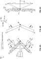
FIGs. 2A-C , diagrams of a top view full panel center rotation in accordance with an embodiment of the inventive concepts disclosed herein are shown. A full panel center rotation diagram 200 may indicate a rotation of each of the leftrotational ESA panel 122 and the rightrotational ESA panel 124 about avertical rotation axis 126 aligned with the longitudinal axis of the aircraft. - In one embodiment of the inventive concepts disclosed herein, the
controller 110 may receive a rotation trigger for commanding the actuator 120 to rotate the at least tworotational ESA panels 122 124 and command theactuator 120 to rotate the at least tworotational ESA panels 122 124 from the first azimuthal position to the second azimuthal position without stopping in an intermediate azimuthal position. In one embodiment, the first azimuthal position and the second azimuthal position are separated by approximately 45 degrees - In embodiments, the rotation trigger may be related to a plurality of factors causing a change in the boresight of the left 122 and right 124 rotational ESA panels. In some embodiments, the rotation trigger may be any of an altitude trigger, a mission trigger, a threat trigger including a radar warning receiver (RWR) indication, a ground proximity warning, a traffic trigger, a manual trigger via pilot interaction with the radar display, and an environmental trigger such as weather, windshear, turbulence, etc. For example, an altitude trigger may be associated with a specific altitude (e.g., below 3000 ft AGL) of the aircraft received by the
positioning system 116. At low altitude, one employment operation may include a forward-looking radar where eachrotational ESA panel 122 124 may be positioned to the second azimuthal position. The altitude related trigger may offer the ability to automatically position the rotational ESA panels to the desiredcommon boresight 152. - In one embodiment, the mission trigger may include a specific desired
common boresight 152 for accomplishing a specific mission. For example, one mission may be a ground mapping radar mission where a forwardcommon boresight 152 may be desirable. A terrain following mission may also provide a mission trigger to cause thecontroller 110 to command a specificcommon boresight 152. Additionally, thecontroller 110 may receive a windshear or traffic alert and cause thecontroller 110 to take action. In one embodiment, the controller may automatically rotate and de-rotate therotational ESA panels 122 124 based on the altitude. - In one embodiment, the common boresight may be aligned with the longitudinal axis of the aircraft to enable a forward-looking radar system for a plurality of mission related purposes (e.g., ground proximity, traffic awareness, weather awareness).
- In one embodiment, the
controller 110 may depower each of therotational ESA panels 122 124 during the rotation. This depower action may function to create a two-position operation of either operation in the first azimuthal position or operation in the second azimuthal position without scanning an azimuth between the two. For example, the leftrotational ESA panel 122 may function in the first azimuthal position with a boresight centered 45 degrees left of the aircraft nose (longitudinal axis). During rotation to the second azimuthal position the leftrotational ESA panel 122 may be depowered during the rotation and unable to scan any azimuth during rotation. Once in the second azimuthal position, thecontroller 110 may repower the leftrotational ESA panel 122 to scan thecommon boresight 152 aligned with the longitudinal axis. - Once the
rotational ESA panels 122 124 are in the second azimuthal position, thecontroller 110 may electronically couple the at least two rotational ESA panels while in the second azimuthal position to coherently operate as asingle aggregate ESA 222 having thecommon boresight 152 and a combinedESA scan volume 150. This may effectively create a larger synthetic planar array whose horizontal size is a plan back projection of the conformal structure. While therotational ESA panels 122 124 are in the second azimuthal position, thecontroller 110 may apply similar controlling logic to thesingle aggregate ESA 222 as applied to each individual rotational ESA prior to the rotation. In this manner, a simple configuration of tworotational ESA panels 122 124 may increase function of the system for mechanically positioning an electronically scannedarray panel 100 by shifting system complexity from a powerful computing device to a simplemechanical actuator 120. - In one embodiment, the
controller 110 may receive a radar signal from the singleaggregate ESA panel 222 having thecommon boresight 152 and display the radar signal on the radar display. Once the rotation trigger may be no longer valid, thecontroller 110 may receive a de-rotation trigger to rotate the at least tworotational ESA panels 122 124 from the second azimuthal position back to the first azimuthal position and command theactuator 120 to rotate the at least tworotational ESA panels 122 124 from the second azimuthal position to the first azimuthal position without stopping in the intermediate azimuthal position. - Of note, the
indicated scan volume 150 may be exemplary only wherein a typical scan volume of an ESA panel may reach 90 degrees either side of the boresight. Here for clarity of diagrams, ascan volume 150 may be displayed in the figures for illustrative purposes only. - In one embodiment of the inventive concepts disclosed herein, the
controller 110 may be configured to command the actuator to perform a calibration of the at least tworotational ESA panels 122 124 to each of the first azimuthal position and the second azimuthal position. Here, as thecontroller 110 may precisely rotate each of therotational ESA panels 122 124, a calibration function embedded within thecontroller 110 may offer a system calibration for ensuring the first azimuthal position and the second azimuthal position are precisely planar. - Referring now to
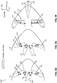
FIGs. 3A-C , diagrams of a partialpanel center rotation 300 exemplary of an embodiment of the inventive concepts disclosed herein are shown. In some embodiments, the system for mechanically positioning an electronically scannedarray panel 100 may be constrained by an internal shape of anaircraft radome 310. In this situation, the system for mechanically positioning an electronically scannedarray panel 100 may not be able to rotate each full panel rotational ESA as inFIGs. 2 . In the first azimuthal position shown inFIG. 3A , each of the four ESA panels is functional and radiating with the two ESA panels on the left having theleft boresight 142 and the two ESA panels on the right having theright boresight 144. Once thecontroller 110 begins the rotation,FIG. 3B may indicate a stationaryleft ESA 322 and a stationaryright ESA 324 remaining in position while therotational ESA panels 122 124 begin to rotation to the second azimuthal position. -
FIG. 3C may indicate each of therotational ESA panels 122 124 complete in the rotation to the second azimuthal position and radiating as thesingle aggregate ESA 222 having thecommon boresight 152 and thescan volume 150. - Referring now to
FIGs. 4A-F , diagrams of a partial panellateral rotation 400 exemplary of one embodiment of the inventive concepts disclosed herein are shown. In one embodiment of the inventive concepts disclosed herein, the system for mechanically positioning an electronically scannedarray panel 100 may function within aradome 310 of smaller size yet still enabling full rotation of the partialrotational ESA panels 122 124 from the first to the second azimuthal position. - Here, a
left actuator 422 and aright actuator 424 may function to rotate the left 122 and right 124 rotational ESA panels about the vertical axes 126 (left and right) laterally displaced from the longitudinal axis of the aircraft. In this manner, internal space required for rotation may be less than a centerline vertical axis of rotation as inFIGs. 2 and3 . - In one embodiment of the inventive concepts disclosed herein, the
single aggregate ESA 222 may include an overlap of the individualrotational ESA panels 122 124 once the rotation is complete. Thecontroller 110 may electrically determine a partial radiation pattern of one of the panels to enable accurate ESA operation. For example, the leftrotational ESA panel 122 may partially function with the partial radiation pattern while the rightrotational ESA panel 124 may fully radiate. -
FIGs. 4D through 4F may indicate an additional embodiment where each of the four ESA panels may rotate about avertical axis 126 displaced from the longitudinal axis. Here, a left outerrotational ESA panel 432 and a right outerrotational ESA panel 434 coupled respectively with therotational ESA panels 122 124 may further rotate the ESA panels to the second azimuthal position. - In one embodiment, the rotational ESA panels may be directed or "aimed" to align their individual boresights at a point in space. Here, a boresight focus may intersect at a single point in the distance or the boresights may be aimed at particular points of an object in the distance.
- In this embodiment, the left and right outer rotational ESA panels may combine to form the
single aggregate ESA 222 when rotated to the second azimuthal position. Although laterally displaced from the longitudinal axis, the left 432 and right 434 outer rotational ESA panels may electrically function as the singleaggregate ESA panel 222 with an appropriate time delay/phase shift applied between the arrays. - Referring now to
FIGs. 5A-C , diagrams of a partial panelcenter translation rotation 500 in accordance with one embodiment of the inventive concepts disclosed herein are shown. In one embodiment of the inventive concepts disclosed herein, the system for mechanically positioning an electronically scannedarray panel 100 may further reduce a size necessary to perform the rotation by translating as well as rotating therotational ESA panels 122 124. Here, theactuator 120 may be positioned on the longitudinal axis of the aircraft and translate a translating axis ofrotation 526 along the longitudinal axis. While the translating axis of rotation moves aft in this scenario, therotational ESA panels 122 124 may also translate outboard along atranslation rotation direction 528 to the second azimuthal position. - In one embodiment, the system for mechanically positioning an electronically scanned
array panel 100 may employ a variety of mechanical subsystems to cause therotational ESA panels 122 124 to translate as well as rotate. For example, anactuator 120 including a precision jackscrew may cause the translating axis ofrotation 526 to translate along the longitudinal axis. - Referring now to
FIGs. 6A-C , diagrams of an exemplary full panel lateral rotation in accordance with one embodiment of the inventive concepts disclosed herein are shown. In one embodiment, the vertical axis ofrotation 126 may be aligned with the longitudinal axis of the aircraft (e.g.,FIG. 2A ), proximally offset from the longitudinal axis of the aircraft (e.g.,FIG. 4A ), and distally offset from the longitudinal axis (e.g.,FIG. 6A ). - Here, the vertical axis of
rotation 126 may be laterally displaced at an outboard edge of therotational ESA panels 122 124. The fullpanel lateral rotation 600 may maintain a significant inside overlap once therotational ESA panels 122 124 are rotated to the second azimuthal position. In this embodiment, the singleaggregate ESA panel 222 may comprise a partialleft radiating ESA 622 and a fullright radiating ESA 624. - Referring now to
FIG. 7A-C , diagrams of a right-side view 700 associated with one embodiment of the inventive concepts disclosed herein are shown. The right-side view 700 may indicate an additional embodiment wherein the system for mechanically positioning an electronically scannedarray panel 100 may further rotate therotational ESA panels 122 124 in elevation about a horizontal axis ofrotation 726 in ahorizontal rotation direction 728. Here,FIG. 7A may indicate theright panel 124 prior to the rotation about the vertical axis.Fig. 7B may indicate thesingle aggregate ESA 222 after the rotation about the vertical axis is complete, andFIG. 7C may detail the elevational rotation about thehorizontal rotation axis 726. - Once the
controller 110 commands thesingle aggregate ESA 222 to the second azimuthal position thecontroller 110 may further rotate thesingle aggregate ESA 222 about thehorizontal rotation axis 726. Once complete, thesingle aggregate ESA 222 may function with acommon boresight 152 angularly displaced from the longitudinal axis. As above, during rotation in both azimuth and elevation, thecontroller 110 may depower eachrotational ESA panel 122 124 and repower each once in the desired position. - In some embodiments, the
system 100 may identify or "tune" the distance between a wall of theradome 310 and the ESA panel to attempt to compensate for radome imperfections and compensation. In this manner, thecontroller 110 may determine each signature of theradome 310 to which it is installed and compensate for various abnormalities within theradome 310 structure. For example, eachradome 310 may include a frame structure, a lighting mitigation structure, and possible fasteners of variable composition (e.g., metallic, ferrous, reflective) through which radar energy may deviate from a perfect boresight. Thecontroller 110 may compensate for these imperfections in processing the reflected radar energy within a specific azimuth of these imperfections. - Referring now to
FIGs. 8A-D , diagrams of a multi-panel rotation diagram 800 exemplary of one embodiment of the inventive concepts disclosed herein are shown. In one embodiment of the inventive concepts disclosed herein, the system for mechanically positioning an electronically scannedarray panel 100 may include a six-panel rotational ESA configuration wherein thecontroller 110 may command a plurality of second azimuthal positions to enable a desiredcommon boresight 152. -
FIG. 8A may indicate the six panel ESA array in a first configuration capable of a threeboresight 142 152 144 operation. In an additional configuration,FIG. 8B may indicate an additional azimuthal position of each of the six ESA panels offering thecontroller 110 an optional beam boresight where a left ESAsecond boresight 442 and a right ESAsecond boresight 444 may provide additional function. - In some embodiments, the ESA panels may be fitted within the
radome 310 in a onetime fit of a "conformal" ESA and optimized conformal aperture size within an arbitrary radome. The subpanels may be coherently combined through time deal compensation to effectively create a conformal ESA. In other embodiments, the rotational ESA panels may be equal or unequal in size as indicated in the previous figures. In each configuration, simultaneous independent beams are possible across all the subpanels. -
FIG. 8C may indicate a folded configuration offering a chevron configuration whileFIG. 8D may indicate each ESA panel operational and radiating in an extended chevron configuration. - In some embodiments, the plurality of rotational ESA may provide a maximum reuse with a standard ESA panel assembly that can be used and reconfigured to be compatible a host of radomes as well as additional applications (e.g., ground vehicles, watercraft, etc.) The reconfiguration may be either a onetime installation or mission dependent dynamic as described above.
- In some embodiments, the mechanical rotation may be asymmetric as the application may demand. Although
FIGs. 8A - 8D may indicate a symmetric rotation, it is contemplated herein an asymmetric rotation (e.g., a left side rotation only) may fall well within the scope of the inventive concepts disclosed herein. - In embodiments, the mechanical rotation may be not at a 100% duty cycle, unlike existing electromechanically scanned systems, so compared with a traditional continuously scanning radar, embodiments of the inventive concepts disclosed herein may consume less DC power and maintain an increase in reliability.
- In some embodiments, the separate sub-panels shown in the drawings may be made time/phase coherent to operate as a composite conformal aperture if the appropriate time delays are incorporated between the subpanels. Subpanels may function having an independently steered beam, may be a coherent conformal array, as well as toggle back and forth between these modes.
- Referring now to
FIG. 9 , a diagram of amethod flow 900 exemplary of one embodiment of the inventive concepts disclosed herein is shown. Themethod flow 900 may include, at astep 902, receiving a rotation trigger for commanding an actuator to rotate at least two rotational ESA panels onboard an aircraft, and, at astep 904, commanding an actuator to mechanically rotate the at least two rotational ESA panels about a vertical axis from a first azimuthal position to a second azimuthal position. - The method may include, at a
step 906, electronically coupling the at least two rotational ESA panels while in the second azimuthal position to function as a single aggregate ESA having a common boresight. The method may further include, at astep 908, receiving a radar signal from the single aggregate ESA having the common boresight and, at astep 910, displaying the radar signal on a radar display onboard the aircraft - As will be appreciated from the above description, embodiments of the inventive concepts disclosed herein may provide a novel solution to simply mechanically rotating a portion or an entirety of two or more ESA panels and electrically combining the rotated ESA panels to form a single aggregate ESA.
- It is to be understood that embodiments of the methods according to the inventive concepts disclosed herein may include one or more of the steps described herein. Further, such steps may be carried out in any desired order and two or more of the steps may be carried out simultaneously with one another. Two or more of the steps disclosed herein may be combined in a single step, and in some embodiments, one or more of the steps may be carried out as two or more sub-steps. Further, other steps or sub-steps may be carried in addition to, or as substitutes to one or more of the steps disclosed herein.
- From the above description, it is clear that the inventive concepts disclosed herein are well adapted to carry out the objects and to attain the advantages mentioned herein as well as those inherent in the inventive concepts disclosed herein. While presently preferred embodiments of the inventive concepts disclosed herein have been described for purposes of this disclosure, it will be understood that numerous changes may be made which will readily suggest themselves to those skilled in the art and which are accomplished within the broad scope and coverage of the inventive concepts disclosed and claimed herein.
Claims (15)
- A system for mechanically positioning an electronically scanned array, ESA, panel, comprising:at least two rotational ESA panels (122, 124) onboard an aircraft, the at least two rotational ESA panels configured for a rotation, the rotation at least about a vertical axis (126);each of the at least two rotational ESA panels individually operational in a first azimuthal position having a first boresight (142, 144) and collectively operational in a second azimuthal position having a common boresight (152), the second azimuthal position of each of the at least two rotational ESA panels being equal, the first azimuthal position distant from the second azimuthal position by the rotation;an actuator (120) coupled with each of the at least two rotational ESA panels, the actuator configured to mechanically cause the rotation;a radar display (114) available to one of a pilot and an autopilot of the aircrafta controller (110) operatively coupled with each of the at least two rotational ESA panels and the actuator;a tangible, non-transitory memory (112) configured to communicate with the controller, the tangible, non-transitory memory having instructions stored therein that, in response to execution by the controller, cause the controller to:receive a rotation trigger for commanding the actuator to rotate the at least two rotational ESA panels;command the actuator to rotate the at least two rotational ESA panels from the first azimuthal position to the second azimuthal position without stopping in an intermediate azimuthal position;electronically couple the at least two rotational ESA panels while in the second azimuthal position to coherently operate as a single aggregate ESA having the common boresight;receive a radar signal from the single aggregate ESA having the common boresight;display the radar signal on the radar display (114);receive a de-rotation trigger to rotate the at least two rotational ESA panels from the second azimuthal position to the first azimuthal position; andcommand the actuator to de-rotate the at least two rotational ESA panels from the second azimuthal position to the first azimuthal position.
- The system for mechanically positioning an ESA panel of claim 1, wherein the the at least two rotational ESA panels further comprises a left rotational ESA panel (122) and a right rotational ESA panel (124), the first boresight (142) of the left rotational ESA panel distant from the first boresight (144) of the right rotational ESA panel by at least approximately 90 degrees.
- The system for mechanically positioning an ESA panel of claim 1 or 2, further comprising a positioning system configured at least for determining an altitude of the aircraft, and wherein the controller automatically rotates and de-rotates based on the altitude.
- The system for mechanically positioning an ESA panel of any preceding claim, wherein the vertical axis is one of: aligned with a longitudinal axis of the aircraft, proximally offset from the longitudinal axis of the aircraft, and distally offset from the longitudinal axis.
- The system for mechanically positioning an ESA panel of any preceding claim, wherein the at least two rotational ESA panels configured for the rotation are one of: a full panel rotation and a partial panel rotation and are depowered during the rotation.
- The system for mechanically positioning an ESA panel of claim 5, wherein the partial panel rotation rotates about a vertical axis one of: aligned with the longitudinal axis of the aircraft, proximally offset from the longitudinal axis of the aircraft, and distally offset from the longitudinal axis.
- The system for mechanically positioning an ESA panel of any preceding claim, wherein commanding the actuator (120) to rotate further comprises a calibration of the at least two rotational ESA panels to each of the first azimuthal position and the second azimuthal position.
- The system for mechanically positioning an ESA panel of any preceding claim, wherein displaying the radar signal on the radar display further comprises an information exchange in a format recognizable by the autopilot.
- The system for mechanically positioning an ESA panel of any preceding claim, wherein the common boresight (152) is aligned with the longitudinal axis of the aircraft.
- The system for mechanically positioning an ESA panel of any preceding claim, wherein the rotation further comprises a horizontal rotation of the single aggregate ESA having the common boresight about a horizontal axis.
- A method for mechanically positioning an electronically scanned array, ESA, panel, comprising:receiving a rotation trigger for commanding an actuator to rotate at least two rotational ESA panels (122, 124) onboard an aircraft;commanding an actuator (120) to mechanically rotate the at least two rotational ESA panels about a vertical axis from a first azimuthal position to a second azimuthal position;electronically coupling the at least two rotational ESA panels while in the second azimuthal position to coherently operate as a single aggregate ESA having a common boresight (152);receiving a radar signal from the single aggregate ESA having the common boresight; anddisplaying the radar signal on a radar display (114) onboard the aircraft.
- The method for mechanically positioning an ESA panel of claim 11, wherein receiving the rotation trigger further comprises one of: an altitude trigger, a mission trigger, a threat trigger, a ground proximity warning, a traffic trigger, a manual trigger, and a weather trigger.
- The method for mechanically positioning an ESA panel of claim 11, wherein the common boresight (152) is aligned with a longitudinal axis of the aircraft.
- The method for mechanically positioning an ESA panel of claim 11, wherein the first azimuthal position and the second azimuthal position are separated by approximately 45 degrees.
- The method for mechanically positioning an ESA panel of claim 11, wherein displaying the radar signal on the radar display (114) onboard the aircraft further comprises providing an autopilot onboard the aircraft with an information based on the radar signal.
Applications Claiming Priority (1)
| Application Number | Priority Date | Filing Date | Title |
|---|---|---|---|
| US17/100,378 US11552395B2 (en) | 2020-11-20 | 2020-11-20 | ESA quadrant mechanical reconfiguration |
Publications (2)
| Publication Number | Publication Date |
|---|---|
| EP4002586A1 true EP4002586A1 (en) | 2022-05-25 |
| EP4002586B1 EP4002586B1 (en) | 2025-07-02 |
Family
ID=78725349
Family Applications (1)
| Application Number | Title | Priority Date | Filing Date |
|---|---|---|---|
| EP21209612.7A Active EP4002586B1 (en) | 2020-11-20 | 2021-11-22 | Esa quadrant mechanical reconfiguration |
Country Status (2)
| Country | Link |
|---|---|
| US (1) | US11552395B2 (en) |
| EP (1) | EP4002586B1 (en) |
Citations (2)
| Publication number | Priority date | Publication date | Assignee | Title |
|---|---|---|---|---|
| US20130214972A1 (en) * | 2012-02-20 | 2013-08-22 | Rockwell Collins, Inc. | Optimized two panel aesa for aircraft applications |
| EP3621155A1 (en) * | 2018-09-04 | 2020-03-11 | Alpha Networks Inc. | Dynamically adjusted antenna system and antenna array included therein |
Family Cites Families (9)
| Publication number | Priority date | Publication date | Assignee | Title |
|---|---|---|---|---|
| US6151496A (en) | 1998-10-22 | 2000-11-21 | Raytheon Company | System and method of performing soft hand-off with one-dimensional AESA |
| US6212471B1 (en) * | 1999-04-28 | 2001-04-03 | Lockheed Martin Corporation | Dynamic optimal sensor employment for searching an area |
| US6169522B1 (en) | 1999-09-03 | 2001-01-02 | Motorola, Inc. | Combined mechanical scanning and digital beamforming antenna |
| US7474263B1 (en) | 2007-10-31 | 2009-01-06 | Raytheon Company | Electronically scanned antenna |
| EP2359437B1 (en) | 2008-11-12 | 2013-10-16 | Saab AB | Method and arrangement for a low radar cross section antenna |
| US20120249366A1 (en) | 2011-04-04 | 2012-10-04 | Raytheon Company | Communications on the move antenna system |
| KR20180026470A (en) * | 2015-07-29 | 2018-03-12 | 퀄컴 인코포레이티드 | Angle and position detection using arrays of antennas |
| FR3068523B1 (en) | 2017-06-30 | 2020-04-03 | Radiall | ANTENNA WITH A TRANSMITTER ARRAY HAVING A BEAM DIRECTION REORIENTATION MECHANISM |
| US10754020B2 (en) * | 2017-08-30 | 2020-08-25 | Honeywell International Inc. | Mechanically assisted phased array for extended scan limits |
-
2020
- 2020-11-20 US US17/100,378 patent/US11552395B2/en active Active
-
2021
- 2021-11-22 EP EP21209612.7A patent/EP4002586B1/en active Active
Patent Citations (2)
| Publication number | Priority date | Publication date | Assignee | Title |
|---|---|---|---|---|
| US20130214972A1 (en) * | 2012-02-20 | 2013-08-22 | Rockwell Collins, Inc. | Optimized two panel aesa for aircraft applications |
| EP3621155A1 (en) * | 2018-09-04 | 2020-03-11 | Alpha Networks Inc. | Dynamically adjusted antenna system and antenna array included therein |
Also Published As
| Publication number | Publication date |
|---|---|
| US11552395B2 (en) | 2023-01-10 |
| EP4002586B1 (en) | 2025-07-02 |
| US20220166136A1 (en) | 2022-05-26 |
Similar Documents
| Publication | Publication Date | Title |
|---|---|---|
| EP2649679B1 (en) | Mobile radar system | |
| KR101779900B1 (en) | Active electronically scanned array radar | |
| US7522095B1 (en) | Polygonal cylinder array antenna | |
| CA3064739C (en) | Apparatus and methods for a synthetic aperture radar with self-cueing | |
| US7250905B2 (en) | Virtual antenna technology (VAT) and applications | |
| US9091745B2 (en) | Optimized two panel AESA for aircraft applications | |
| EP4063894A1 (en) | Multi-beam multi-function aesa system | |
| JP7013136B2 (en) | Secondary radar that can detect objects at high elevation angles | |
| US9337536B1 (en) | Electronically steerable SATCOM antenna | |
| US11754706B2 (en) | Agile antenna taper based on weather radar feedback | |
| US7928890B2 (en) | Phased array radar antenna having reduced search time and method for use thereof | |
| Kinghorn et al. | Recent advances in airborne phased array radar systems | |
| Sharay et al. | TECSAR: Design considerations and programme status | |
| CN106972262A (en) | A kind of spaceborne GNSS R multi-beams phased array antenna and its method | |
| EP4002586B1 (en) | Esa quadrant mechanical reconfiguration | |
| US12415621B2 (en) | Satellite with spot light mode for extended duration target imaging | |
| Huizing et al. | Compact scalable multifunction RF payload for UAVs with FMCW radar and ESM functionality | |
| US20250012919A1 (en) | Ground clutter suppression and runway imaging via radar ground mapping | |
| Liu et al. | The geodesic dome phased array antenna for satellite operations support-antenna resource management | |
| CN108092001A (en) | The antenna that a kind of satellite communication mechanical scanning is combined with phase controlling | |
| Schrank | Aircraft radar antennas | |
| Rait | Quasi-optical discrete lens arrays for synthetic aperture radar | |
| Lacomme | Impact of STAP processing on antenna design | |
| Freeman et al. | A Low Cost Phase Array Solution for UAV Collision Avoidance |
Legal Events
| Date | Code | Title | Description |
|---|---|---|---|
| PUAI | Public reference made under article 153(3) epc to a published international application that has entered the european phase |
Free format text: ORIGINAL CODE: 0009012 |
|
| STAA | Information on the status of an ep patent application or granted ep patent |
Free format text: STATUS: THE APPLICATION HAS BEEN PUBLISHED |
|
| AK | Designated contracting states |
Kind code of ref document: A1 Designated state(s): AL AT BE BG CH CY CZ DE DK EE ES FI FR GB GR HR HU IE IS IT LI LT LU LV MC MK MT NL NO PL PT RO RS SE SI SK SM TR |
|
| STAA | Information on the status of an ep patent application or granted ep patent |
Free format text: STATUS: REQUEST FOR EXAMINATION WAS MADE |
|
| 17P | Request for examination filed |
Effective date: 20221123 |
|
| RBV | Designated contracting states (corrected) |
Designated state(s): AL AT BE BG CH CY CZ DE DK EE ES FI FR GB GR HR HU IE IS IT LI LT LU LV MC MK MT NL NO PL PT RO RS SE SI SK SM TR |
|
| GRAP | Despatch of communication of intention to grant a patent |
Free format text: ORIGINAL CODE: EPIDOSNIGR1 |
|
| STAA | Information on the status of an ep patent application or granted ep patent |
Free format text: STATUS: GRANT OF PATENT IS INTENDED |
|
| RIC1 | Information provided on ipc code assigned before grant |
Ipc: H01Q 1/28 20060101ALN20250127BHEP Ipc: G01S 7/40 20060101ALN20250127BHEP Ipc: G01S 13/02 20060101ALN20250127BHEP Ipc: H01Q 3/12 20060101ALI20250127BHEP Ipc: H01Q 21/06 20060101ALI20250127BHEP Ipc: H01Q 25/00 20060101ALI20250127BHEP Ipc: H01Q 3/30 20060101ALI20250127BHEP Ipc: H01Q 3/26 20060101ALI20250127BHEP Ipc: H01Q 3/06 20060101ALI20250127BHEP Ipc: H01Q 3/04 20060101ALI20250127BHEP Ipc: H01Q 3/01 20060101AFI20250127BHEP |
|
| INTG | Intention to grant announced |
Effective date: 20250206 |
|
| GRAS | Grant fee paid |
Free format text: ORIGINAL CODE: EPIDOSNIGR3 |
|
| GRAA | (expected) grant |
Free format text: ORIGINAL CODE: 0009210 |
|
| STAA | Information on the status of an ep patent application or granted ep patent |
Free format text: STATUS: THE PATENT HAS BEEN GRANTED |
|
| AK | Designated contracting states |
Kind code of ref document: B1 Designated state(s): AL AT BE BG CH CY CZ DE DK EE ES FI FR GB GR HR HU IE IS IT LI LT LU LV MC MK MT NL NO PL PT RO RS SE SI SK SM TR |
|
| REG | Reference to a national code |
Ref country code: GB Ref legal event code: FG4D |
|
| REG | Reference to a national code |
Ref country code: CH Ref legal event code: EP |
|
| REG | Reference to a national code |
Ref country code: DE Ref legal event code: R096 Ref document number: 602021033249 Country of ref document: DE |
|
| REG | Reference to a national code |
Ref country code: IE Ref legal event code: FG4D |
|
| REG | Reference to a national code |
Ref country code: NL Ref legal event code: MP Effective date: 20250702 |
|
| PG25 | Lapsed in a contracting state [announced via postgrant information from national office to epo] |
Ref country code: PT Free format text: LAPSE BECAUSE OF FAILURE TO SUBMIT A TRANSLATION OF THE DESCRIPTION OR TO PAY THE FEE WITHIN THE PRESCRIBED TIME-LIMIT Effective date: 20251103 |
|
| PG25 | Lapsed in a contracting state [announced via postgrant information from national office to epo] |
Ref country code: NL Free format text: LAPSE BECAUSE OF FAILURE TO SUBMIT A TRANSLATION OF THE DESCRIPTION OR TO PAY THE FEE WITHIN THE PRESCRIBED TIME-LIMIT Effective date: 20250702 |
|
| REG | Reference to a national code |
Ref country code: AT Ref legal event code: MK05 Ref document number: 1810361 Country of ref document: AT Kind code of ref document: T Effective date: 20250702 |
|
| PG25 | Lapsed in a contracting state [announced via postgrant information from national office to epo] |
Ref country code: IS Free format text: LAPSE BECAUSE OF FAILURE TO SUBMIT A TRANSLATION OF THE DESCRIPTION OR TO PAY THE FEE WITHIN THE PRESCRIBED TIME-LIMIT Effective date: 20251102 |
|
| PGFP | Annual fee paid to national office [announced via postgrant information from national office to epo] |
Ref country code: DE Payment date: 20251022 Year of fee payment: 5 |
|
| PGFP | Annual fee paid to national office [announced via postgrant information from national office to epo] |
Ref country code: GB Payment date: 20251022 Year of fee payment: 5 |
|
| PG25 | Lapsed in a contracting state [announced via postgrant information from national office to epo] |
Ref country code: NO Free format text: LAPSE BECAUSE OF FAILURE TO SUBMIT A TRANSLATION OF THE DESCRIPTION OR TO PAY THE FEE WITHIN THE PRESCRIBED TIME-LIMIT Effective date: 20251002 |
|
| REG | Reference to a national code |
Ref country code: LT Ref legal event code: MG9D |
|
| PG25 | Lapsed in a contracting state [announced via postgrant information from national office to epo] |
Ref country code: AT Free format text: LAPSE BECAUSE OF FAILURE TO SUBMIT A TRANSLATION OF THE DESCRIPTION OR TO PAY THE FEE WITHIN THE PRESCRIBED TIME-LIMIT Effective date: 20250702 |
|
| PG25 | Lapsed in a contracting state [announced via postgrant information from national office to epo] |
Ref country code: FI Free format text: LAPSE BECAUSE OF FAILURE TO SUBMIT A TRANSLATION OF THE DESCRIPTION OR TO PAY THE FEE WITHIN THE PRESCRIBED TIME-LIMIT Effective date: 20250702 |
|
| PG25 | Lapsed in a contracting state [announced via postgrant information from national office to epo] |
Ref country code: HR Free format text: LAPSE BECAUSE OF FAILURE TO SUBMIT A TRANSLATION OF THE DESCRIPTION OR TO PAY THE FEE WITHIN THE PRESCRIBED TIME-LIMIT Effective date: 20250702 |
|
| PGFP | Annual fee paid to national office [announced via postgrant information from national office to epo] |
Ref country code: FR Payment date: 20251022 Year of fee payment: 5 |
|
| PG25 | Lapsed in a contracting state [announced via postgrant information from national office to epo] |
Ref country code: GR Free format text: LAPSE BECAUSE OF FAILURE TO SUBMIT A TRANSLATION OF THE DESCRIPTION OR TO PAY THE FEE WITHIN THE PRESCRIBED TIME-LIMIT Effective date: 20251003 |
|
| PG25 | Lapsed in a contracting state [announced via postgrant information from national office to epo] |
Ref country code: SE Free format text: LAPSE BECAUSE OF FAILURE TO SUBMIT A TRANSLATION OF THE DESCRIPTION OR TO PAY THE FEE WITHIN THE PRESCRIBED TIME-LIMIT Effective date: 20250702 Ref country code: CZ Free format text: LAPSE BECAUSE OF FAILURE TO SUBMIT A TRANSLATION OF THE DESCRIPTION OR TO PAY THE FEE WITHIN THE PRESCRIBED TIME-LIMIT Effective date: 20250702 |
|
| PG25 | Lapsed in a contracting state [announced via postgrant information from national office to epo] |
Ref country code: LV Free format text: LAPSE BECAUSE OF FAILURE TO SUBMIT A TRANSLATION OF THE DESCRIPTION OR TO PAY THE FEE WITHIN THE PRESCRIBED TIME-LIMIT Effective date: 20250702 |
|
| PG25 | Lapsed in a contracting state [announced via postgrant information from national office to epo] |
Ref country code: PL Free format text: LAPSE BECAUSE OF FAILURE TO SUBMIT A TRANSLATION OF THE DESCRIPTION OR TO PAY THE FEE WITHIN THE PRESCRIBED TIME-LIMIT Effective date: 20250702 Ref country code: BG Free format text: LAPSE BECAUSE OF FAILURE TO SUBMIT A TRANSLATION OF THE DESCRIPTION OR TO PAY THE FEE WITHIN THE PRESCRIBED TIME-LIMIT Effective date: 20250702 |
|
| PG25 | Lapsed in a contracting state [announced via postgrant information from national office to epo] |
Ref country code: RS Free format text: LAPSE BECAUSE OF FAILURE TO SUBMIT A TRANSLATION OF THE DESCRIPTION OR TO PAY THE FEE WITHIN THE PRESCRIBED TIME-LIMIT Effective date: 20251002 |
|
| PG25 | Lapsed in a contracting state [announced via postgrant information from national office to epo] |
Ref country code: ES Free format text: LAPSE BECAUSE OF FAILURE TO SUBMIT A TRANSLATION OF THE DESCRIPTION OR TO PAY THE FEE WITHIN THE PRESCRIBED TIME-LIMIT Effective date: 20250702 |
|
| PG25 | Lapsed in a contracting state [announced via postgrant information from national office to epo] |
Ref country code: RO Free format text: LAPSE BECAUSE OF FAILURE TO SUBMIT A TRANSLATION OF THE DESCRIPTION OR TO PAY THE FEE WITHIN THE PRESCRIBED TIME-LIMIT Effective date: 20250702 |
|
| PG25 | Lapsed in a contracting state [announced via postgrant information from national office to epo] |
Ref country code: SM Free format text: LAPSE BECAUSE OF FAILURE TO SUBMIT A TRANSLATION OF THE DESCRIPTION OR TO PAY THE FEE WITHIN THE PRESCRIBED TIME-LIMIT Effective date: 20250702 |
|
| PG25 | Lapsed in a contracting state [announced via postgrant information from national office to epo] |
Ref country code: DK Free format text: LAPSE BECAUSE OF FAILURE TO SUBMIT A TRANSLATION OF THE DESCRIPTION OR TO PAY THE FEE WITHIN THE PRESCRIBED TIME-LIMIT Effective date: 20250702 |
|
| PG25 | Lapsed in a contracting state [announced via postgrant information from national office to epo] |
Ref country code: IT Free format text: LAPSE BECAUSE OF FAILURE TO SUBMIT A TRANSLATION OF THE DESCRIPTION OR TO PAY THE FEE WITHIN THE PRESCRIBED TIME-LIMIT Effective date: 20250702 |
|
| PG25 | Lapsed in a contracting state [announced via postgrant information from national office to epo] |
Ref country code: SK Free format text: LAPSE BECAUSE OF FAILURE TO SUBMIT A TRANSLATION OF THE DESCRIPTION OR TO PAY THE FEE WITHIN THE PRESCRIBED TIME-LIMIT Effective date: 20250702 Ref country code: EE Free format text: LAPSE BECAUSE OF FAILURE TO SUBMIT A TRANSLATION OF THE DESCRIPTION OR TO PAY THE FEE WITHIN THE PRESCRIBED TIME-LIMIT Effective date: 20250702 |
|
| PLBE | No opposition filed within time limit |
Free format text: ORIGINAL CODE: 0009261 |
|
| STAA | Information on the status of an ep patent application or granted ep patent |
Free format text: STATUS: NO OPPOSITION FILED WITHIN TIME LIMIT |