EP4002070B1 - Electromagnetic handwriting system and electromagnetic handwriting input method - Google Patents
Electromagnetic handwriting system and electromagnetic handwriting input method Download PDFInfo
- Publication number
- EP4002070B1 EP4002070B1 EP21199353.0A EP21199353A EP4002070B1 EP 4002070 B1 EP4002070 B1 EP 4002070B1 EP 21199353 A EP21199353 A EP 21199353A EP 4002070 B1 EP4002070 B1 EP 4002070B1
- Authority
- EP
- European Patent Office
- Prior art keywords
- electromagnetic
- electromagnetic handwriting
- handwriting tablet
- frequency value
- state
- Prior art date
- Legal status (The legal status is an assumption and is not a legal conclusion. Google has not performed a legal analysis and makes no representation as to the accuracy of the status listed.)
- Active
Links
Images




Classifications
-
- G—PHYSICS
- G06—COMPUTING OR CALCULATING; COUNTING
- G06F—ELECTRIC DIGITAL DATA PROCESSING
- G06F3/00—Input arrangements for transferring data to be processed into a form capable of being handled by the computer; Output arrangements for transferring data from processing unit to output unit, e.g. interface arrangements
- G06F3/01—Input arrangements or combined input and output arrangements for interaction between user and computer
- G06F3/03—Arrangements for converting the position or the displacement of a member into a coded form
- G06F3/041—Digitisers, e.g. for touch screens or touch pads, characterised by the transducing means
- G06F3/046—Digitisers, e.g. for touch screens or touch pads, characterised by the transducing means by electromagnetic means
-
- G—PHYSICS
- G06—COMPUTING OR CALCULATING; COUNTING
- G06F—ELECTRIC DIGITAL DATA PROCESSING
- G06F3/00—Input arrangements for transferring data to be processed into a form capable of being handled by the computer; Output arrangements for transferring data from processing unit to output unit, e.g. interface arrangements
- G06F3/01—Input arrangements or combined input and output arrangements for interaction between user and computer
- G06F3/03—Arrangements for converting the position or the displacement of a member into a coded form
- G06F3/033—Pointing devices displaced or positioned by the user, e.g. mice, trackballs, pens or joysticks; Accessories therefor
- G06F3/0354—Pointing devices displaced or positioned by the user, e.g. mice, trackballs, pens or joysticks; Accessories therefor with detection of two-dimensional [2D] relative movements between the device, or an operating part thereof, and a plane or surface, e.g. 2D mice, trackballs, pens or pucks
- G06F3/03545—Pens or stylus
-
- G—PHYSICS
- G06—COMPUTING OR CALCULATING; COUNTING
- G06F—ELECTRIC DIGITAL DATA PROCESSING
- G06F3/00—Input arrangements for transferring data to be processed into a form capable of being handled by the computer; Output arrangements for transferring data from processing unit to output unit, e.g. interface arrangements
- G06F3/01—Input arrangements or combined input and output arrangements for interaction between user and computer
- G06F3/03—Arrangements for converting the position or the displacement of a member into a coded form
- G06F3/033—Pointing devices displaced or positioned by the user, e.g. mice, trackballs, pens or joysticks; Accessories therefor
- G06F3/038—Control and interface arrangements therefor, e.g. drivers or device-embedded control circuitry
-
- G—PHYSICS
- G06—COMPUTING OR CALCULATING; COUNTING
- G06F—ELECTRIC DIGITAL DATA PROCESSING
- G06F3/00—Input arrangements for transferring data to be processed into a form capable of being handled by the computer; Output arrangements for transferring data from processing unit to output unit, e.g. interface arrangements
- G06F3/01—Input arrangements or combined input and output arrangements for interaction between user and computer
- G06F3/03—Arrangements for converting the position or the displacement of a member into a coded form
- G06F3/041—Digitisers, e.g. for touch screens or touch pads, characterised by the transducing means
- G06F3/0416—Control or interface arrangements specially adapted for digitisers
- G06F3/04166—Details of scanning methods, e.g. sampling time, grouping of sub areas or time sharing with display driving
-
- G—PHYSICS
- G06—COMPUTING OR CALCULATING; COUNTING
- G06F—ELECTRIC DIGITAL DATA PROCESSING
- G06F3/00—Input arrangements for transferring data to be processed into a form capable of being handled by the computer; Output arrangements for transferring data from processing unit to output unit, e.g. interface arrangements
- G06F3/01—Input arrangements or combined input and output arrangements for interaction between user and computer
- G06F3/03—Arrangements for converting the position or the displacement of a member into a coded form
- G06F3/041—Digitisers, e.g. for touch screens or touch pads, characterised by the transducing means
- G06F3/044—Digitisers, e.g. for touch screens or touch pads, characterised by the transducing means by capacitive means
- G06F3/0442—Digitisers, e.g. for touch screens or touch pads, characterised by the transducing means by capacitive means using active external devices, e.g. active pens, for transmitting changes in electrical potential to be received by the digitiser
Definitions
- the present disclosure relates to the technical field of computer peripheral devices, and more particular, relates to an electromagnetic handwriting system and an electromagnetic handwriting input method.
- Electromagnetic handwriting systems are commonly used computer input peripheral devices.
- An electromagnetic handwriting system typically includes an electromagnetic stylus and an electromagnetic handwriting tablet, operates based on the electromagnetic induction principle, and has merits of high precision, pressure sensing, and the like.
- the electromagnetic handwriting system is widely applied in the fields of computer-aided drawing, game making, film special effect rendering, electronic endorsing and the like.
- the electromagnetic handwriting tablet When a user writes, signs signature or makes drawings on the electromagnetic handwriting tablet with the electromagnetic stylus, the electromagnetic handwriting tablet captures a movement trajectory and pressure sensing data of the electromagnetic stylus based on the electromagnetic induction principle, and transmits handwriting input data to a computer.
- the computer receives the handwriting input data, and processes the handwriting input data to generate corresponding texts or graphics and output the same to a display device for display.
- the electromagnetic stylus emits a drive signal.
- the electromagnetic handwriting tablet receives the drive signal.
- the drive signal drives the electromagnetic handwriting tablet to be in a suspension state, an enable state, or a writing state.
- an electromagnetic pressure-sensitive pointer comprises a pen core and an oscillating circuit.
- the pointer core has a pointer tip.
- the oscillating circuit comprises a plurality of conductive terminals and a conductor. A capacitance of the oscillating circuit is increased through the contact between the conductive terminals and the conductor as a force is applied upon the pointer tip. When pointer's tip is been pressed, the pointer's frequency will have an obvious transition while its pressure-sensitivity is maintained.
- a frequency value at which the electromagnetic handwriting tablet enters the suspension state is set as a suspension state frequency threshold f0
- a frequency value at which the electromagnetic handwriting tablet enters the enable state is set as an enable state frequency threshold f1.
- a difference ⁇ f
- is present between f0 and f1.
- Defect 1 When the electromagnetic stylus is received on the electromagnetic handwriting tablet, a lag is caused during entry into the enable state of the electromagnetic handwriting tablet.
- the pressure applied by the user with the electromagnetic stylus onto the electromagnetic handwriting tablet progressively increases from zero, and ft increases accordingly, as illustrated in a curved line segment AC in FIG. 1 .
- Defect 2 When the electromagnetic stylus leaves from the electromagnetic handwriting tablet, the enable state is interrupted in advance and the stroke disappears.
- the pressure applied by the electromagnetic stylus onto the electromagnetic handwriting tablet progressively decreases, and ft decreases accordingly, as illustrated in a curved line segment CE in FIG. 1 .
- the present disclosure provides an electromagnetic handwriting system and an electromagnetic handwriting input method.
- the electromagnetic handwriting system including an electromagnetic handwriting tablet configured to receive a drive signal, the drive signal driving the electromagnetic handwriting tablet to be in a suspension state or an enable state; wherein, a frequency value at which the electromagnetic handwriting tablet enters the suspension state is set as a suspension state frequency threshold f0; a frequency value at which the electromagnetic handwriting tablet enters the enable state is set as an enable state frequency threshold f1; wherein,if an actual frequency value of the drive signal received by the electromagnetic handwriting tablet is set to ft, and a virtual frequency value fx is set to satisfy
- the suspension state frequency threshold f0 is less than the enable state frequency threshold f1, and the virtual frequency value fx satisfies f0 ⁇ fx ⁇ f1.
- the suspension state frequency threshold f0 is greater than the enable state frequency threshold f1, and the virtual frequency value fx satisfies f0>fx>f1.
- the electromagnetic handwriting input method including: providing an electromagnetic handwriting tablet and receiving a drive signal, wherein the electromagnetic handwriting tablet includes a suspension state and an enable state; and,setting a suspension state frequency threshold of the electromagnetic handwriting tablet to f0, and setting an enable state frequency threshold of the electromagnetic handwriting tablet to f1, wherein the electromagnetic handwriting tablet is configured to measure and calculate a frequency value ft of the drive signal, and if a virtual frequency value fx is set to satisfy
- the suspension state frequency threshold f0 is less than the enable state frequency threshold f1, and the virtual frequency value fx satisfies f0 ⁇ fx ⁇ f1.
- the suspension state frequency threshold f0 is greater than the enable state frequency threshold f1, and the virtual frequency value fx satisfies f0>fx>f1.
- a lag is caused during entry into the enable state of the electromagnetic handwriting tablet.
- a frequency value at which the electromagnetic handwriting tablet enters the suspension state is set as a suspension state frequency threshold f0
- a frequency value at which the electromagnetic handwriting tablet enters the enable state is set as an enable state frequency threshold f1
- an actual frequency value of the drive signal received by the electromagnetic handwriting tablet is set to ft
- a virtual frequency value fx is set to satisfy
- the electromagnetic handwriting tablet is configured to smooth and filter the actual frequency value ft to output frequency data f(ft), wherein when f0 ⁇ ft ⁇ fx, ft is the virtual frequency value fx.
- f0 ⁇ fx ⁇ f1 is taken as an example to illustrate the display mode of its beneficial effect.
- the receiving time is reduced,when the electromagnetic stylus leaves from the system, according to the actual handwriting, an effect of gradual fading of the stroke is better exhibited, and the real handwriting is vividly restored.
- FIG. 2 is a schematic structural view of an electromagnetic handwriting system 10 according to a first embodiment of the present disclosure
- FIG. 3 is a flow block diagram of the electromagnetic handwriting system in FIG. 2
- the electromagnetic handwriting system 10 includes an electromagnetic stylus 11 and an electromagnetic handwriting tablet 13.
- the electromagnetic stylus 11 emits a drive signal.
- the drive signal drives the electromagnetic handwriting tablet 13 to be in a suspension state, an enable state, or a writing state.
- a frequency value at which the electromagnetic handwriting tablet 13 enters the suspension state is set as a suspension state frequency threshold f0
- a frequency value at which the electromagnetic handwriting tablet 13 enters the enable state is set as an enable state frequency threshold f1, f1>f0
- an actual frequency value of the drive signal received by the electromagnetic handwriting tablet 13 is set to ft
- the electromagnetic handwriting tablet 13 smooths and filters ft to output frequency data f(ft).
- the electromagnetic stylus 11 includes an oscillator circuit 111 and a power module 113.
- the power module 113 charges the oscillator circuit 111.
- the oscillator circuit 111 is an LC circuit.
- the oscillator circuit 111 emits the drive signal according to an operating state of the electromagnetic stylus 11.
- the operating state of the electromagnetic stylus 11 includes a suspension state, an enable state, and a writing state.
- the suspension state of the electromagnetic stylus 11 corresponds to the suspension state of the electromagnetic handwriting tablet 13.
- the enable state of the electromagnetic stylus 11 corresponds to the enable state of the electromagnetic handwriting tablet 13.
- the writing state of the electromagnetic stylus 11 corresponds to the writing state of the electromagnetic handwriting tablet 13.
- a pressure applied by the electromagnetic stylus 11 onto the electromagnetic handwriting tablet 13 changes, the electromagnetic stylus 11 switches from the suspension state to the enable state, and correspondingly, the electromagnetic handwriting tablet 13 switches from the suspension state to the enable state.
- the electromagnetic handwriting tablet 13 includes an antenna board 131, a receiving module 133, a processing module 135, and a control module 137.
- the receiving module 133 controls the antenna board 131 to receive the drive signal, and transmits the drive signal to the processing module 135.
- the processing module 135 outputs an amplitude of the drive signal, and transmits the amplitude to the control module 137.
- the control module 137 includes a processor 1371 and a filter 1372.
- the processor 1371 calculates the actual frequency value ft of the drive signal based on the amplitude.
- the filter 1372 smooths and filters ft.
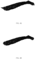
- FIG. 4A and FIG. 4B a writing effect of the electromagnetic handwriting system in FIG. 2 and a writing effect in the related art are respectively illustrated.
- the receiving time is reduced, that is, a switching period of the electromagnetic handwriting tablet 13 from the suspension state to the enable state is shortened, writing flexibility is improved, a lag before entry into the enable state is reduced.
- the electromagnetic handwriting system 20 includes an electromagnetic stylus 21 and an electromagnetic handwriting tablet 23.
- the electromagnetic stylus 21 emits a drive signal.
- the drive signal drives the electromagnetic handwriting tablet 23 to be in a suspension state, an enable state, or a writing state.
- a frequency value at which the electromagnetic handwriting tablet 23 enters the suspension state is set as a suspension state frequency threshold f0
- a frequency value at which the electromagnetic handwriting tablet 23 enters the enable state is set as an enable state frequency threshold f1, f1 ⁇ f0
- an actual frequency value of the drive signal received by the electromagnetic handwriting tablet 23 is set to ft
- the electromagnetic handwriting tablet 23 smooths and filters ft to output frequency data f(ft).
- the electromagnetic stylus 21 includes an oscillator circuit 211 and a power module 213.
- the power module 213 charges the oscillator circuit 211.
- the oscillator circuit 211 is an LC circuit.
- the oscillator circuit 211 emits the drive signal according to an operating state of the electromagnetic stylus. When the electromagnetic stylus 21 is being used, the actual frequency value ft of the drive signal is changed by changing an inductance coefficient of an inductor or a capacitance value of a capacitor.
- the electromagnetic handwriting tablet 23 includes an antenna board 231, a receiving module 233, a processing module 235, and a control module 237.
- the receiving module 233 controls the antenna board 231 to receive the drive signal, and transmits the drive signal to the processing module 235.
- the processing module 235 outputs an amplitude of the drive signal, and transmits the amplitude to the control module 237.
- the control module 237 controls other modules to perform respective operations thereof.
- the control module 237 includes a processor 2371 and a filter 2372.
- the processor 2371 calculates the actual frequency value ft of the drive signal based on the amplitude.
- the filter 2372 smooths and filters ft.
- the power module 213 charges the oscillator circuit 211.
- the oscillator circuit 211 emits a drive signal according to the operating state of the electromagnetic stylus 21.
- the receiving module 233 controls the antenna board 231 to receive the drive signal; and the receiving module 233 processes the drive signal, amplifies the drive signal, and transmits the drive signal to the processing module 235.
- the processing module 235 processes the drive signal, outputs an amplitude of the drive signal, and transmits the amplitude to the processor 2371.
- the processor 2371 calculates the actual frequency value ft of the drive signal based on the amplitude.
- the virtual frequency value fx is set to satisfy f0>fx>f1.
- the actual frequency value ft is adjusted to fx.
- the processor 2371 transmits the calculated and adjusted ft to the filter 2372.
- the filter 2372 smooths and filters the calculated and adjusted ft, and outputs frequency data f(ft).
- FIG. 6 is a schematic structural view of an electromagnetic handwriting system 30 according to a third embodiment of the present disclosure
- FIG. 7 is a flow block diagram of the electromagnetic handwriting system in FIG. 6
- the electromagnetic handwriting system 30 includes an electromagnetic stylus 31 and an electromagnetic handwriting tablet 33.
- the electromagnetic handwriting tablet 33 emits an excitation signal.
- the electromagnetic stylus 31 receives the excitation signal and emits a drive signal.
- the drive signal drives the electromagnetic handwriting tablet 33 to be in a suspension state, an enable state, or a writing state.
- a frequency value at which the electromagnetic handwriting tablet 33 enters the suspension state is set as a suspension state frequency threshold f0
- a frequency value at which the electromagnetic handwriting tablet 33 enters the enable state is set as an enable state frequency threshold f1, f1>f0
- an actual frequency value of the drive signal received by the electromagnetic handwriting tablet 33 is set to ft
- the electromagnetic handwriting tablet 33 smooths and filters ft to output frequency data f(ft).
- the electromagnetic stylus 31 includes a resonator circuit 311.
- the resonator circuit 311 receives the excitation signal, and then emits the drive signal according to the operating state of the electromagnetic stylus 31.
- the resonator circuit 311 includes an inductor and a capacitor. The inductor and the capacitor are electrically connected to each other. When the electromagnetic stylus 31 is being used, the actual frequency value ft of the drive signal is changed by changing an inductance coefficient of an inductor or a capacitance value of a capacitor.
- the electromagnetic handwriting tablet 33 includes an antenna board 331, a sending module 332, a receiving module 333, a processing module 335, and a control module 337.
- the sending module 332 controls the antenna board 331 to emit the excitation signal.
- the receiving module 333 controls the antenna board 331 to receive the drive signal, and transmits the drive signal to the processing module 335.
- the processing module 335 outputs an amplitude of the drive signal, and transmits the amplitude to the control module 337.
- the control module 337 controls other modules to perform respective operations thereof.
- the control module 337 includes a processor 3371 and a filter 3372.
- the processor 3371 calculates the actual frequency value ft of the drive signal based on the amplitude.
- the filter 3372 smooths and filters ft.
- Stylus receiving and leaving effects of the electromagnetic handwriting system 30 are the same as those of the electromagnetic handwriting system 10, which are not described herein any further.
- the electromagnetic handwriting system 40 includes an electromagnetic stylus 41 and an electromagnetic handwriting tablet 43.
- the electromagnetic handwriting tablet 43 emits an excitation signal.
- the electromagnetic stylus 41 receives the excitation signal and emits a drive signal.
- the drive signal drives the electromagnetic handwriting tablet 43 to be in a suspension state, an enable state, or a writing state.
- a frequency value at which the electromagnetic handwriting tablet 43 enters the suspension state is set as a suspension state frequency threshold f0
- a frequency value at which the electromagnetic handwriting tablet 43 enters the enable state is set as an enable state frequency threshold f1, f1 ⁇ f0
- an actual frequency value of the drive signal received by the electromagnetic handwriting tablet 43 is set to ft
- the electromagnetic handwriting tablet 43 smooths and filters ft to output frequency data f(ft).
- the electromagnetic stylus 41 includes a resonator circuit 411.
- the electromagnetic handwriting tablet 43 includes an antenna board 431, a sending module 432, a receiving module 433, a processing module 435, and a control module 437.
- the control module 437 includes a processor 4371 and a filter 4372.
- the operating principle of the electromagnetic handwriting system 40 is substantially the same as that of the electromagnetic handwriting system 30, and the only difference therebetween lies in that:
- the processor 4371 calculates the actual frequency value ft of the drive signal based on the amplitude; the virtual frequency value fx is set to satisfy f0>fx>f1; when f0>ft>fx, the actual frequency value ft is adjusted to fx; and the processor 4371 transmits the calculated and adjusted ft to the filter 4372.
- Stylus receiving and leaving effects of the electromagnetic handwriting system 40 are the same as those of the electromagnetic handwriting system 20, which are not described herein any further.
Landscapes
- Engineering & Computer Science (AREA)
- General Engineering & Computer Science (AREA)
- Theoretical Computer Science (AREA)
- Physics & Mathematics (AREA)
- Human Computer Interaction (AREA)
- General Physics & Mathematics (AREA)
- Electromagnetism (AREA)
- User Interface Of Digital Computer (AREA)
- Position Input By Displaying (AREA)
- Arrangements For Transmission Of Measured Signals (AREA)
Description
- The present disclosure relates to the technical field of computer peripheral devices, and more particular, relates to an electromagnetic handwriting system and an electromagnetic handwriting input method.
- Electromagnetic handwriting systems are commonly used computer input peripheral devices. An electromagnetic handwriting system typically includes an electromagnetic stylus and an electromagnetic handwriting tablet, operates based on the electromagnetic induction principle, and has merits of high precision, pressure sensing, and the like. The electromagnetic handwriting system is widely applied in the fields of computer-aided drawing, game making, film special effect rendering, electronic endorsing and the like.
- When a user writes, signs signature or makes drawings on the electromagnetic handwriting tablet with the electromagnetic stylus, the electromagnetic handwriting tablet captures a movement trajectory and pressure sensing data of the electromagnetic stylus based on the electromagnetic induction principle, and transmits handwriting input data to a computer. The computer receives the handwriting input data, and processes the handwriting input data to generate corresponding texts or graphics and output the same to a display device for display.
- In the related art, during use, the electromagnetic stylus emits a drive signal. The electromagnetic handwriting tablet receives the drive signal. The drive signal drives the electromagnetic handwriting tablet to be in a suspension state, an enable state, or a writing state.
- In document
US2019/0235649 A1 , an electromagnetic pressure-sensitive pointer is disclosed. The electromagnetic pointer comprises a pen core and an oscillating circuit. The pointer core has a pointer tip. The oscillating circuit comprises a plurality of conductive terminals and a conductor. A capacitance of the oscillating circuit is increased through the contact between the conductive terminals and the conductor as a force is applied upon the pointer tip. When pointer's tip is been pressed, the pointer's frequency will have an obvious transition while its pressure-sensitivity is maintained. - A frequency value at which the electromagnetic handwriting tablet enters the suspension state is set as a suspension state frequency threshold f0, and a frequency value at which the electromagnetic handwriting tablet enters the enable state is set as an enable state frequency threshold f1. A difference Δf=|f1-f0| is present between f0 and f1. An actual frequency value of the drive signal received by the electromagnetic handwriting tablet from the electromagnetic stylus is set to ft, ft=

- The defects in the related art are described herein using the fact that the greater the pressure is, smaller the inductance coefficient L is, and greater ft is
- Defect 1: When the electromagnetic stylus is received on the electromagnetic handwriting tablet, a lag is caused during entry into the enable state of the electromagnetic handwriting tablet.
- In the process that the electromagnetic stylus is in suspension and approaching the electromagnetic handwriting tablet, the electromagnetic stylus applies no pressure onto the electromagnetic handwriting tablet, the electromagnetic stylus is in the suspension state, and ft=f0, as illustrated by a straight-line segment A1A in
FIG. 1 . - When the electromagnetic stylus is in contact with the electromagnetic handwriting tablet, the pressure applied by the user with the electromagnetic stylus onto the electromagnetic handwriting tablet progressively increases from zero, and ft increases accordingly, as illustrated in a curved line segment AC in
FIG. 1 . - When ft is greater than f0, that is, in the process that ft progressively increases from f0, due to the presence of the difference Δf=|f1-f0|, as illustrated in a curved line segment AB in
FIG. 1 , when f0<ft<f1, that is, in the process of switching between the suspension state to the enable state, it is probable that the electromagnetic stylus has been in contact with the electromagnetic handwriting tablet but the stroke lagging appears. - Defect 2: When the electromagnetic stylus leaves from the electromagnetic handwriting tablet, the enable state is interrupted in advance and the stroke disappears.
- In the process that the user lifts the electromagnetic stylus away from the electromagnetic handwriting tablet, the pressure applied by the electromagnetic stylus onto the electromagnetic handwriting tablet progressively decreases, and ft decreases accordingly, as illustrated in a curved line segment CE in
FIG. 1 . In the process that ft progressively decreases to f0, due to the presence of the difference Δf=|f1-f0|, as illustrated in a curved line segment DE inFIG. 1 , when f0<ft<f1, that is, in the process of switching between the enable state and the suspension state, it is probable that the electromagnetic stylus still acts on the electromagnetic handwriting tablet but the electromagnetic stylus is not in the enable state and the stroke disappears in advance. - Therefore, it is desired to provide a method to address the above two defects.
- In order to accomplish above problem, the present disclosure provides an electromagnetic handwriting system and an electromagnetic handwriting input method.
- The electromagnetic handwriting system, including an electromagnetic handwriting tablet configured to receive a drive signal, the drive signal driving the electromagnetic handwriting tablet to be in a suspension state or an enable state; wherein,a frequency value at which the electromagnetic handwriting tablet enters the suspension state is set as a suspension state frequency threshold f0;a frequency value at which the electromagnetic handwriting tablet enters the enable state is set as an enable state frequency threshold f1; wherein,if an actual frequency value of the drive signal received by the electromagnetic handwriting tablet is set to ft, and a virtual frequency value fx is set to satisfy |f0-f1|>|f0-fx| and |f0-f1|>|fx-f1|,then when ft satisfies |f0-fx|>|f0-ft| and |f0-fx|>|ft-fx|, ft is adjusted to fx in response to driving the electromagnetic handwriting tablet.
- According to an embodiment, the suspension state frequency threshold f0 is less than the enable state frequency threshold f1, and the virtual frequency value fx satisfies f0<fx<f1.
- According to an embodiment, when ft progressively increases from f0, the electromagnetic handwriting tablet is configured to smooth and filter the actual frequency value ft to output frequency data f(ft), wherein when f0≤ft<fx, ft is the virtual frequency value fx, and when f(ft)=fl, the electromagnetic handwriting tablet enters the enable state.
- According to an embodiment, when ft progressively decreases to f0, the electromagnetic handwriting tablet is configured to smooth and filter the actual frequency value ft to output frequency data f(ft), wherein when f0≤ft<fx, ft is the virtual frequency value fx, and when f(ft)=fl, the electromagnetic handwriting tablet enters the enable state.
- According to an embodiment, the suspension state frequency threshold f0 is greater than the enable state frequency threshold f1, and the virtual frequency value fx satisfies f0>fx>f1.
- According to an embodiment, when ft progressively decreases from f0, the electromagnetic handwriting tablet is configured to smooth and filter the actual frequency value ft to output frequency data f(ft), wherein when f0≥ft>fx, ft is the virtual frequency value fx, and when f(ft)=fl, the electromagnetic handwriting tablet enters the enable state.
- According to an embodiment, when ft progressively increases to f0, the electromagnetic handwriting tablet is configured to smooth and filter the actual frequency value ft to output frequency data f(ft), wherein when f0≥ft>fx, ft is the virtual frequency value fx, and when f(ft)=fl, the electromagnetic handwriting tablet enters the enable state.
- The electromagnetic handwriting input method, including: providing an electromagnetic handwriting tablet and receiving a drive signal, wherein the electromagnetic handwriting tablet includes a suspension state and an enable state; and,setting a suspension state frequency threshold of the electromagnetic handwriting tablet to f0, and setting an enable state frequency threshold of the electromagnetic handwriting tablet to f1, wherein the electromagnetic handwriting tablet is configured to measure and calculate a frequency value ft of the drive signal, and if a virtual frequency value fx is set to satisfy |f0-f1|>|f0-fx| and |f0-f1|>|fx-f1|, then when ft satisfies |f0-fx|>|f0-ft| and |f0-fx|>|ft-fx|, the electromagnetic handwriting tablet is correspondingly driven to adjust ft to fx.
- According to an embodiment, the suspension state frequency threshold f0 is less than the enable state frequency threshold f1, and the virtual frequency value fx satisfies f0<fx<f1.
- According to an embodiment, when ft progressively increases from f0, the electromagnetic handwriting tablet is configured to smooth and filter the actual frequency value ft to output frequency data f(ft), wherein when f0≤ft<fx, ft is the virtual frequency value fx, and when f(ft)=fl, the electromagnetic handwriting tablet enters the enable state.
- According to an embodiment, when ft progressively decreases to f0, the electromagnetic handwriting tablet is configured to smooth and filter the actual frequency value ft to output frequency data f(ft), wherein when f0≤ft<fx, ft is the virtual frequency value fx, and when f(ft)=fl, the electromagnetic handwriting tablet enters the enable state.
- According to an embodiment, the suspension state frequency threshold f0 is greater than the enable state frequency threshold f1, and the virtual frequency value fx satisfies f0>fx>f1.
- According to an embodiment, when ft progressively decreases from f0, the electromagnetic handwriting tablet is configured to smooth and filter the actual frequency value ft to output frequency data f(ft), wherein when f0≥ft>fx, ft is the virtual frequency value fx, and when f(ft)=fl, the electromagnetic handwriting tablet enters the enable state.
- According to an embodiment, when ft progressively increases to f0, the electromagnetic handwriting tablet is configured to smooth and filter the actual frequency value ft to output frequency data f(ft), wherein when f0≥ft>fx, ft is the virtual frequency value fx, and when f(ft)=fl, the electromagnetic handwriting tablet enters the enable state.
- As compared with the related art, the electromagnetic handwriting input method a lag is caused during entry into the enable state of the electromagnetic handwriting tablet. a frequency value at which the electromagnetic handwriting tablet enters the suspension state is set as a suspension state frequency threshold f0, a frequency value at which the electromagnetic handwriting tablet enters the enable state is set as an enable state frequency threshold f1, an actual frequency value of the drive signal received by the electromagnetic handwriting tablet is set to ft, if an actual frequency value of the drive signal received by the electromagnetic handwriting tablet is set to ft, and a virtual frequency value fx is set to satisfy |f0-f1|>|f0-fx| and |f0-f1|>|fx-f1|,then when ft satisfies |f0-fx|>|f0-ft| and |f0-fx|>|ft-fx|, ft is adjusted to fx in response to driving the electromagnetic handwriting tablet.
- Then the electromagnetic handwriting tablet is configured to smooth and filter the actual frequency value ft to output frequency data f(ft), wherein when f0≤ft<fx, ft is the virtual frequency value fx.
- For the convenience of understanding, f0 < fx < f1 is taken as an example to illustrate the display mode of its beneficial effect.
- When the system receives the electromagnetic stylus, the pressure applied by the electromagnetic stylus onto the electromagnetic handwriting tablet progressively increases, the electromagnetic handwriting tablet switches from the suspension state to the enable state, and ft progressively increases from f0. Since when ft<fx, the electromagnetic handwriting tablet adjusts ft to fx, upon smoothing and filtering, when f(ft)=fl, f0<ft<f1, the pressure is not zero, and the electromagnetic handwriting tablet enters the enable state in advance.
- When the electromagnetic stylus leaves from the system, the pressure applied by the electromagnetic stylus onto the electromagnetic handwriting tablet progressively decreases, the electromagnetic handwriting tablet switches from the enable state to the suspension state, and ft progressively decreases to f0. Since when ft<fx, the electromagnetic handwriting tablet adjusts ft to fx, upon smoothing and filtering, when f(ft)=fl, f0<ft<f1, the pressure is not zero, and a lag is caused during entry into the enable state of the electromagnetic handwriting tablet.
- When f0>fx>ft, and the electromagnetic stylus is received by the electromagnetic handwriting system, the receiving time is reduced,when the electromagnetic stylus leaves from the system, according to the actual handwriting, an effect of gradual fading of the stroke is better exhibited, and the real handwriting is vividly restored.
- Many aspects of the exemplary embodiments can be better understood with reference to the following drawings. The components in the drawing are not necessarily drawn to scale, the emphasis instead being placed upon clearly illustrating the principles of the present disclosure.
-
FIG. 1 is a schematic diagram of frequency value change in the prior art; -
FIG. 2 is a schematic structural view of anelectromagnetic handwriting system 10 according to a first embodiment of the present disclosure; -
FIG. 3 is a flow block diagram of the electromagnetic handwriting system inFIG. 2 ; -
FIG. 4A and FIG. 4B , a writing effect of the electromagnetic handwriting system inFIG. 2 and a writing effect in the related art are respectively illustrated; -
FIG. 5 is a schematic structural diagram of an electromagnetic handwriting system according to a second embodiment of the present disclosure is illustrated; -
FIG. 6 is a schematic structural view of anelectromagnetic handwriting system 30 according to a third embodiment of the present disclosure; -
FIG. 7 is a flow block diagram of the electromagnetic handwriting system inFIG. 6 ; -
FIG. 8 is a schematic structural diagram of an electromagnetic handwriting system according to a fourth embodiment of the present disclosure is illustrated. - The present disclosure will hereinafter be described in detail with reference to several exemplary embodiments. To make the technical problems to be solved, technical solutions and beneficial effects of the present disclosure more apparent, the present disclosure is described in further detail together with the figure and the embodiments. It should be understood the specific embodiments described hereby is only to explain the disclosure, not intended to limit the disclosure.
- Referring to
FIG. 2 andFIG. 3 ,FIG. 2 is a schematic structural view of anelectromagnetic handwriting system 10 according to a first embodiment of the present disclosure, andFIG. 3 is a flow block diagram of the electromagnetic handwriting system inFIG. 2 . Theelectromagnetic handwriting system 10 includes anelectromagnetic stylus 11 and anelectromagnetic handwriting tablet 13. Theelectromagnetic stylus 11 emits a drive signal. The drive signal drives theelectromagnetic handwriting tablet 13 to be in a suspension state, an enable state, or a writing state. - In this embodiment, a frequency value at which the
electromagnetic handwriting tablet 13 enters the suspension state is set as a suspension state frequency threshold f0, a frequency value at which theelectromagnetic handwriting tablet 13 enters the enable state is set as an enable state frequency threshold f1, f1>f0, an actual frequency value of the drive signal received by theelectromagnetic handwriting tablet 13 is set to ft, and theelectromagnetic handwriting tablet 13 smooths and filters ft to output frequency data f(ft). In this case: - When f(ft)=f0, the
electromagnetic handwriting tablet 13 is in the suspension state; - when f0<f(ft)<f1, the
electromagnetic handwriting tablet 13 is in a state of switching between the suspension state and the enable state; - when f(ft)=fl, the
electromagnetic handwriting tablet 13 is in the enable state; and - when f(ft)>f1, the
electromagnetic handwriting tablet 13 is in the writing state. - The
electromagnetic stylus 11 includes anoscillator circuit 111 and apower module 113. Thepower module 113 charges theoscillator circuit 111. Theoscillator circuit 111 is an LC circuit. Theoscillator circuit 111 emits the drive signal according to an operating state of theelectromagnetic stylus 11. When theelectromagnetic stylus 11 is being used, the actual frequency value ft of the drive signal is changed by changing an inductance coefficient or a capacitance value of the LC circuit. The operating state of theelectromagnetic stylus 11 includes a suspension state, an enable state, and a writing state. The suspension state of theelectromagnetic stylus 11 corresponds to the suspension state of theelectromagnetic handwriting tablet 13. The enable state of theelectromagnetic stylus 11 corresponds to the enable state of theelectromagnetic handwriting tablet 13. The writing state of theelectromagnetic stylus 11 corresponds to the writing state of theelectromagnetic handwriting tablet 13. As a pressure applied by theelectromagnetic stylus 11 onto theelectromagnetic handwriting tablet 13 changes, theelectromagnetic stylus 11 switches from the suspension state to the enable state, and correspondingly, theelectromagnetic handwriting tablet 13 switches from the suspension state to the enable state. - The
electromagnetic handwriting tablet 13 includes anantenna board 131, a receivingmodule 133, aprocessing module 135, and acontrol module 137. The receivingmodule 133 controls theantenna board 131 to receive the drive signal, and transmits the drive signal to theprocessing module 135. Theprocessing module 135 outputs an amplitude of the drive signal, and transmits the amplitude to thecontrol module 137. Thecontrol module 137 includes aprocessor 1371 and afilter 1372. Theprocessor 1371 calculates the actual frequency value ft of the drive signal based on the amplitude. Thefilter 1372 smooths and filters ft. - When the
electromagnetic handwriting system 10 operates: - In step S01, the
power module 113 charges theoscillator circuit 111. - In step S02, the
oscillator circuit 111 emits a drive signal according to the operating state of theelectromagnetic stylus 11. - In step S03, under control of the
control module 137, the receivingmodule 133 controls theantenna board 131 to receive the drive signal; and the receivingmodule 133 processes the drive signal, amplifies the drive signal, and transmits the drive signal to theprocessing module 135. - In step S04, under control of the
control module 137, theprocessing module 135 processes the drive signal, outputs an amplitude of the drive signal, and transmits the amplitude to theprocessor 1371. - In step S05, the
processor 1371 calculates the actual frequency value ft of the drive signal based on the amplitude. The virtual frequency value fx is set to satisfy f0<fx<f1. When f0≤ft<fx, the actual frequency value ft is adjusted to fx. Theprocessor 1371 transmits the calculated and adjusted ft to thefilter 1372. - In step S06, the
filter 1372 smooths and filters the calculated and adjusted ft, and outputs frequency data f(ft). When f(ft)=fl, the electromagnetic handwriting tablet enters the enable state. - Referring to
FIG. 4A and FIG. 4B , a writing effect of the electromagnetic handwriting system inFIG. 2 and a writing effect in the related art are respectively illustrated. As compared with the related art, a user writes with theelectromagnetic handwriting system 10, and when the system receives the electromagnetic stylus, the pressure applied by theelectromagnetic stylus 11 onto theelectromagnetic handwriting tablet 13 progressively increases, the electromagnetic handwriting tablet switches from the suspension state to the enable state, and ft progressively increases from f0. Since when ft<fx, the electromagnetic handwriting tablet adjusts ft to fx, upon smoothing and filtering, when f(ft)=fl, f0<ft<f1, the pressure is not zero, and the electromagnetic handwriting tablet enters the enable state in advance. Therefore, when the electromagnetic stylus is received by the electromagnetic handwriting system, the receiving time is reduced, that is, a switching period of theelectromagnetic handwriting tablet 13 from the suspension state to the enable state is shortened, writing flexibility is improved, a lag before entry into the enable state is reduced. - When the electromagnetic stylus leaves from the system, the pressure applied by the electromagnetic stylus onto the electromagnetic handwriting tablet progressively decreases, the electromagnetic handwriting tablet switches from the enable state to the suspension state, and ft progressively decreases to f0. Since when ft<fx, the electromagnetic handwriting tablet adjusts ft to fx, upon smoothing and filtering, when f(ft)=fl, f0<ft<f1, the pressure is not zero, and a lag is caused during entry into the enable state of the electromagnetic handwriting tablet. Therefore, when the electromagnetic stylus leaves from the system, according to the actual handwriting, an effect of gradual fading of the stroke is better exhibited, and the real handwriting is vividly restored.
- Referring to
FIG. 5 , a schematic structural diagram of an electromagnetic handwriting system according to a second embodiment of the present disclosure is illustrated. Theelectromagnetic handwriting system 20 includes anelectromagnetic stylus 21 and anelectromagnetic handwriting tablet 23. Theelectromagnetic stylus 21 emits a drive signal. The drive signal drives theelectromagnetic handwriting tablet 23 to be in a suspension state, an enable state, or a writing state. - In this embodiment, a frequency value at which the
electromagnetic handwriting tablet 23 enters the suspension state is set as a suspension state frequency threshold f0, a frequency value at which theelectromagnetic handwriting tablet 23 enters the enable state is set as an enable state frequency threshold f1, f1<f0, an actual frequency value of the drive signal received by theelectromagnetic handwriting tablet 23 is set to ft, and theelectromagnetic handwriting tablet 23 smooths and filters ft to output frequency data f(ft). In this case: - When f(ft)=f0, the
electromagnetic handwriting tablet 23 is in the suspension state; - when f1<f(ft)<f0, the
electromagnetic handwriting tablet 23 is in a state of switching between the suspension state and the enable state; - when f(ft)=fl, the
electromagnetic handwriting tablet 23 is in the enable state; and - when f(ft)<f1, the
electromagnetic handwriting tablet 23 is in the writing state. - The
electromagnetic stylus 21 includes an oscillator circuit 211 and apower module 213. Thepower module 213 charges the oscillator circuit 211. The oscillator circuit 211 is an LC circuit. The oscillator circuit 211 emits the drive signal according to an operating state of the electromagnetic stylus. When theelectromagnetic stylus 21 is being used, the actual frequency value ft of the drive signal is changed by changing an inductance coefficient of an inductor or a capacitance value of a capacitor. - The
electromagnetic handwriting tablet 23 includes anantenna board 231, a receivingmodule 233, aprocessing module 235, and acontrol module 237. The receivingmodule 233 controls theantenna board 231 to receive the drive signal, and transmits the drive signal to theprocessing module 235. Theprocessing module 235 outputs an amplitude of the drive signal, and transmits the amplitude to thecontrol module 237. Thecontrol module 237 controls other modules to perform respective operations thereof. Thecontrol module 237 includes aprocessor 2371 and afilter 2372. Theprocessor 2371 calculates the actual frequency value ft of the drive signal based on the amplitude. Thefilter 2372 smooths and filters ft. - When the
electromagnetic handwriting system 20 operates:
Thepower module 213 charges the oscillator circuit 211. - The oscillator circuit 211 emits a drive signal according to the operating state of the
electromagnetic stylus 21. - Under control of the
control module 237, the receivingmodule 233 controls theantenna board 231 to receive the drive signal; and the receivingmodule 233 processes the drive signal, amplifies the drive signal, and transmits the drive signal to theprocessing module 235. - Under control of the
control module 237, theprocessing module 235 processes the drive signal, outputs an amplitude of the drive signal, and transmits the amplitude to theprocessor 2371. - The
processor 2371 calculates the actual frequency value ft of the drive signal based on the amplitude. The virtual frequency value fx is set to satisfy f0>fx>f1. When f0>ft>fx, the actual frequency value ft is adjusted to fx. Theprocessor 2371 transmits the calculated and adjusted ft to thefilter 2372. - The
filter 2372 smooths and filters the calculated and adjusted ft, and outputs frequency data f(ft). When f(ft)=fl, the electromagnetic handwriting tablet enters the enable state. - As compared with the related art, a user writes with the
electromagnetic handwriting system 20, and when the system receives the electromagnetic stylus, the pressure applied by theelectromagnetic stylus 21 onto theelectromagnetic handwriting tablet 23 progressively increases, the electromagnetic handwriting tablet switches from the suspension state to the enable state, and ft progressively decreases from f0. Since when f0>ft>fx, the electromagnetic handwriting tablet adjusts ft to fx, upon smoothing and filtering, when f(ft)=fl, f0>ft>f1, the pressure is not zero, and the electromagnetic handwriting tablet enters the enable state in advance. Therefore, when the electromagnetic stylus is received by the electromagnetic handwriting system, the receiving time is reduced. - When the electromagnetic stylus leaves from the system, the pressure applied by the electromagnetic stylus onto the electromagnetic handwriting tablet progressively decreases, the electromagnetic handwriting tablet switches from the enable state to the suspension state, and ft progressively increases to f0. Since when f0>ft>fx, the electromagnetic handwriting tablet adjusts ft to fx, upon smoothing and filtering, when f(ft)=fl, f0<ft<f1, the pressure is not zero, and a lag is caused during entry into the enable state of the electromagnetic handwriting tablet. Therefore, when the electromagnetic stylus leaves from the system, according to the actual handwriting, an effect of gradual fading of the stroke is better exhibited, and the real handwriting is vividly restored.
- Referring to
FIG. 6 andFIG. 7 ,FIG. 6 is a schematic structural view of anelectromagnetic handwriting system 30 according to a third embodiment of the present disclosure, andFIG. 7 is a flow block diagram of the electromagnetic handwriting system inFIG. 6 . Theelectromagnetic handwriting system 30 includes anelectromagnetic stylus 31 and anelectromagnetic handwriting tablet 33. Theelectromagnetic handwriting tablet 33 emits an excitation signal. Theelectromagnetic stylus 31 receives the excitation signal and emits a drive signal. The drive signal drives theelectromagnetic handwriting tablet 33 to be in a suspension state, an enable state, or a writing state. - In this embodiment, a frequency value at which the
electromagnetic handwriting tablet 33 enters the suspension state is set as a suspension state frequency threshold f0, a frequency value at which theelectromagnetic handwriting tablet 33 enters the enable state is set as an enable state frequency threshold f1, f1>f0, an actual frequency value of the drive signal received by theelectromagnetic handwriting tablet 33 is set to ft, and theelectromagnetic handwriting tablet 33 smooths and filters ft to output frequency data f(ft). In this case: - When f(ft)=f0, the
electromagnetic handwriting tablet 33 is in the suspension state; - when f0<f(ft)<f1, the
electromagnetic handwriting tablet 33 is in a state of switching between the suspension state and the enable state; - when f(ft)=fl, the
electromagnetic handwriting tablet 33 is in the enable state; and - when f(ft)>f1, the
electromagnetic handwriting tablet 33 is in the writing state. - The
electromagnetic stylus 31 includes aresonator circuit 311. Theresonator circuit 311 receives the excitation signal, and then emits the drive signal according to the operating state of theelectromagnetic stylus 31. Theresonator circuit 311 includes an inductor and a capacitor. The inductor and the capacitor are electrically connected to each other. When theelectromagnetic stylus 31 is being used, the actual frequency value ft of the drive signal is changed by changing an inductance coefficient of an inductor or a capacitance value of a capacitor. - The
electromagnetic handwriting tablet 33 includes anantenna board 331, a sendingmodule 332, a receivingmodule 333, aprocessing module 335, and acontrol module 337. The sendingmodule 332 controls theantenna board 331 to emit the excitation signal. The receivingmodule 333 controls theantenna board 331 to receive the drive signal, and transmits the drive signal to theprocessing module 335. Theprocessing module 335 outputs an amplitude of the drive signal, and transmits the amplitude to thecontrol module 337. Thecontrol module 337 controls other modules to perform respective operations thereof. Thecontrol module 337 includes aprocessor 3371 and afilter 3372. Theprocessor 3371 calculates the actual frequency value ft of the drive signal based on the amplitude. Thefilter 3372 smooths and filters ft. - When the
electromagnetic handwriting system 30 operates: - In step SS01, under control of the
control module 337, the sendingmodule 332 controls the antenna board to emit an excitation signal. - In step SS02, the
resonator circuit 311 receives the excitation signal, and emits the drive signal according to the operating state of theelectromagnetic stylus 31. - In step SS03, under control of the
control module 337, the receivingmodule 333 controls theantenna board 331 to receive the drive signal; and the receivingmodule 333 processes the drive signal, amplifies the drive signal, and transmits the drive signal to theprocessing module 335. - In step SS04, under control of the
control module 337, theprocessing module 335 processes the drive signal, outputs an amplitude of the drive signal, and transmits the amplitude to theprocessor 3371. - In step SS05, the
processor 3371 calculates the actual frequency value ft of the drive signal based on the amplitude. The virtual frequency value fx is set to satisfy f0<fx<f1. When f0≤ft<fx, the actual frequency value ft is adjusted to fx. Theprocessor 3371 transmits the calculated and adjusted ft to thefilter 3372. - In step SS06, the
filter 3372 smooths and filters the calculated and adjusted ft, and outputs frequency data f(ft). When f(ft)=fl, the electromagnetic handwriting tablet enters the enable state. - Stylus receiving and leaving effects of the
electromagnetic handwriting system 30 are the same as those of theelectromagnetic handwriting system 10, which are not described herein any further. - Referring to
FIG. 8 , a schematic structural diagram of an electromagnetic handwriting system according to a fourth embodiment of the present disclosure is illustrated. Theelectromagnetic handwriting system 40 includes anelectromagnetic stylus 41 and anelectromagnetic handwriting tablet 43. Theelectromagnetic handwriting tablet 43 emits an excitation signal. Theelectromagnetic stylus 41 receives the excitation signal and emits a drive signal. The drive signal drives theelectromagnetic handwriting tablet 43 to be in a suspension state, an enable state, or a writing state. - In this embodiment, a frequency value at which the
electromagnetic handwriting tablet 43 enters the suspension state is set as a suspension state frequency threshold f0, a frequency value at which theelectromagnetic handwriting tablet 43 enters the enable state is set as an enable state frequency threshold f1, f1<f0, an actual frequency value of the drive signal received by theelectromagnetic handwriting tablet 43 is set to ft, and theelectromagnetic handwriting tablet 43 smooths and filters ft to output frequency data f(ft). In this case: - When f(ft)=f0, the
electromagnetic handwriting tablet 43 is in the suspension state; - when f1<f(ft)<f0, the
electromagnetic handwriting tablet 43 is in a state of switching between the suspension state and the enable state; - when f(ft)=fl, the
electromagnetic handwriting tablet 43 is in the enable state; and - when f(ft)<f1, the
electromagnetic handwriting tablet 43 is in the writing state. - The
electromagnetic stylus 41 includes aresonator circuit 411. - The
electromagnetic handwriting tablet 43 includes anantenna board 431, a sendingmodule 432, a receivingmodule 433, aprocessing module 435, and acontrol module 437. Thecontrol module 437 includes aprocessor 4371 and afilter 4372. - The operating principle of the
electromagnetic handwriting system 40 is substantially the same as that of theelectromagnetic handwriting system 30, and the only difference therebetween lies in that: Theprocessor 4371 calculates the actual frequency value ft of the drive signal based on the amplitude; the virtual frequency value fx is set to satisfy f0>fx>f1; when f0>ft>fx, the actual frequency value ft is adjusted to fx; and theprocessor 4371 transmits the calculated and adjusted ft to thefilter 4372. - Stylus receiving and leaving effects of the
electromagnetic handwriting system 40 are the same as those of theelectromagnetic handwriting system 20, which are not described herein any further. - It is to be understood, however, that even though numerous characteristics and advantages of the present exemplary embodiments have been set forth in the foregoing description, together with details of the structures and functions of the embodiments, the disclosure is illustrative only, and changes may be made in detail, especially in matters of shape, size, and arrangement of parts within the principles of the invention to the full extent indicated by the broad general meaning of the terms where the appended claims are expressed.
Claims (14)
- An electromagnetic handwriting system, comprising:an electromagnetic handwriting tablet configured to receive a drive signal, the drive signal driving the electromagnetic handwriting tablet to be in a suspension state or an enable state;characterized in thata frequency value at which the electromagnetic handwriting tablet enters the suspension state is set as a suspension state frequency threshold f0;a frequency value at which the electromagnetic handwriting tablet enters the enable state is set as an enable state frequency threshold f1; whereinif an actual frequency value of the drive signal received by the electromagnetic handwriting tablet is set to ft, and a virtual frequency value fx is set to satisfy |f0-f1|>|f0-fx| and |f0-f1|>|fx-f1|,then when ft satisfies |f0-fx|>|f0-ft| and |f0-fx|>|ft-fx|, ft is adjusted to fx in response to driving the electromagnetic handwriting tablet.
- The system according to claim 1, wherein the suspension state frequency threshold f0 is less than the enable state frequency threshold f1, and the virtual frequency value fx satisfies f0<fx<f1.
- The system according to claim 2, wherein when ft progressively increases from f0, the electromagnetic handwriting tablet is configured to smooth and filter the actual frequency value ft to output frequency data f(ft), wherein when f0≤ft<fx, ft is the virtual frequency value fx, and when f(ft)=fl, the electromagnetic handwriting tablet enters the enable state.
- The system according to claim 2, wherein when ft progressively decreases to f0, the electromagnetic handwriting tablet is configured to smooth and filter the actual frequency value ft to output frequency data f(ft), wherein when f0≤ft<fx, ft is the virtual frequency value fx, and when f(ft)=fl, the electromagnetic handwriting tablet enters the enable state.
- The system according to claim 1, wherein the suspension state frequency threshold f0 is greater than the enable state frequency threshold f1, and the virtual frequency value fx satisfies f0>fx>f1.
- The system according to claim 5, wherein when ft progressively decreases from f0, the electromagnetic handwriting tablet is configured to smooth and filter the actual frequency value ft to output frequency data f(ft), wherein when f0≥ft>fx, ft is the virtual frequency value fx, and when f(ft)=fl, the electromagnetic handwriting tablet enters the enable state.
- The system according to claim 5, wherein when ft progressively increases to f0, the electromagnetic handwriting tablet is configured to smooth and filter the actual frequency value ft to output frequency data f(ft), wherein when f0≥ft>fx, ft is the virtual frequency value fx, and when f(ft)=fl, the electromagnetic handwriting tablet enters the enable state.
- An electromagnetic handwriting input method, comprising:providing an electromagnetic handwriting tablet and receiving a drive signal, wherein the electromagnetic handwriting tablet comprises a suspension state and an enable state;characterized bysetting a suspension state frequency threshold of the electromagnetic handwriting tablet to f0, and setting an enable state frequency threshold of the electromagnetic handwriting tablet to f1, wherein the electromagnetic handwriting tablet is configured to measure and calculate a frequency value ft of the drive signal, and if a virtual frequency value fx is set to satisfy |f0-f1|>|f0-fx| and |f0-f1|>|fx-f1|, then when ft satisfies |f0-fx|>|f0-ft| and |f0-fx|>|ft-fx|, the electromagnetic handwriting tablet is correspondingly driven to adjust ft to fx.
- The method according to claim 8, wherein the suspension state frequency threshold f0 is less than the enable state frequency threshold f1, and the virtual frequency value fx satisfies f0<fx<f1.
- The method according to claim 9, wherein when ft progressively increases from f0, the electromagnetic handwriting tablet is configured to smooth and filter the actual frequency value ft to output frequency data f(ft), wherein when f0≤ft<fx, ft is the virtual frequency value fx, and when f(ft)=fl, the electromagnetic handwriting tablet enters the enable state.
- The method according to claim 9, wherein when ft progressively decreases to f0, the electromagnetic handwriting tablet is configured to smooth and filter the actual frequency value ft to output frequency data f(ft), wherein when f0≤ft<fx, ft is the virtual frequency value fx, and when f(ft)=fl, the electromagnetic handwriting tablet enters the enable state.
- The method according to claim 8, wherein the suspension state frequency threshold f0 is greater than the enable state frequency threshold f1, and the virtual frequency value fx satisfies f0>fx>f1.
- The method according to claim 12, wherein when ft progressively decreases from f0, the electromagnetic handwriting tablet is configured to smooth and filter the actual frequency value ft to output frequency data f(ft), wherein when f0≥ft>fx, ft is the virtual frequency value fx, and when f(ft)=fl, the electromagnetic handwriting tablet enters the enable state.
- The method according to claim 12, wherein when ft progressively increases to f0, the electromagnetic handwriting tablet is configured to smooth and filter the actual frequency value ft to output frequency data f(ft), wherein when f0≥ft>fx, ft is the virtual frequency value fx, and when f(ft)=fl, the electromagnetic handwriting tablet enters the enable state.
Applications Claiming Priority (1)
| Application Number | Priority Date | Filing Date | Title |
|---|---|---|---|
| CN202011328379.0A CN112462957B (en) | 2020-11-24 | 2020-11-24 | Electromagnetic handwriting system and electromagnetic handwriting input method |
Publications (3)
| Publication Number | Publication Date |
|---|---|
| EP4002070A1 EP4002070A1 (en) | 2022-05-25 |
| EP4002070B1 true EP4002070B1 (en) | 2023-09-20 |
| EP4002070C0 EP4002070C0 (en) | 2023-09-20 |
Family
ID=74799115
Family Applications (1)
| Application Number | Title | Priority Date | Filing Date |
|---|---|---|---|
| EP21199353.0A Active EP4002070B1 (en) | 2020-11-24 | 2021-09-28 | Electromagnetic handwriting system and electromagnetic handwriting input method |
Country Status (6)
| Country | Link |
|---|---|
| US (1) | US11513654B2 (en) |
| EP (1) | EP4002070B1 (en) |
| JP (1) | JP7292342B2 (en) |
| KR (1) | KR102516294B1 (en) |
| CN (1) | CN112462957B (en) |
| TW (1) | TWI804938B (en) |
Family Cites Families (11)
| Publication number | Priority date | Publication date | Assignee | Title |
|---|---|---|---|---|
| JPH1031545A (en) * | 1996-07-17 | 1998-02-03 | Nippon Syst Kaihatsu Kk | Input device |
| US20080129709A1 (en) * | 2006-12-01 | 2008-06-05 | Chun-Lin Lin | Electromagnetic Pen With Amplitude-Controlled Inking Function |
| CN101539816B (en) * | 2009-04-16 | 2012-10-17 | 台均科技(深圳)有限公司 | Electromagnetic pen, electromagnetic signal processing method, device and equipment |
| CN102004566A (en) * | 2010-11-30 | 2011-04-06 | 汉王科技股份有限公司 | Electromagnetic handwritten device |
| CN103064577B (en) * | 2011-10-19 | 2015-08-26 | 汉王科技股份有限公司 | The input method of electromagnetic touch and device |
| TWI518555B (en) | 2012-11-30 | 2016-01-21 | 和冠股份有限公司 | Electromagnetic pointer and control method |
| US9946391B2 (en) * | 2014-11-26 | 2018-04-17 | Synaptics Incorporated | Sensing objects using multiple transmitter frequencies |
| CZ2016111A3 (en) | 2016-02-25 | 2016-11-09 | O.Pen S.R.O. | Wireless positioning pen with pressure tip |
| TWI608385B (en) * | 2016-12-16 | 2017-12-11 | 矽統科技股份有限公司 | Active stylus |
| JP7109201B2 (en) | 2018-01-29 | 2022-07-29 | 株式会社ワコム | A method performed by a pen or pen detection device for detecting said pen |
| CN110119215B (en) * | 2019-05-24 | 2024-08-23 | 深圳市优笔触控科技有限公司 | Double-coil wireless passive digital electromagnetic handwriting pen |
-
2020
- 2020-11-24 CN CN202011328379.0A patent/CN112462957B/en active Active
-
2021
- 2021-07-30 TW TW110128173A patent/TWI804938B/en active
- 2021-09-27 KR KR1020210127566A patent/KR102516294B1/en active Active
- 2021-09-27 JP JP2021156493A patent/JP7292342B2/en active Active
- 2021-09-28 EP EP21199353.0A patent/EP4002070B1/en active Active
- 2021-10-12 US US17/498,860 patent/US11513654B2/en active Active
Also Published As
| Publication number | Publication date |
|---|---|
| US11513654B2 (en) | 2022-11-29 |
| CN112462957A (en) | 2021-03-09 |
| JP7292342B2 (en) | 2023-06-16 |
| US20220164046A1 (en) | 2022-05-26 |
| KR20220071884A (en) | 2022-05-31 |
| TW202221472A (en) | 2022-06-01 |
| KR102516294B1 (en) | 2023-03-31 |
| TWI804938B (en) | 2023-06-11 |
| CN112462957B (en) | 2024-08-27 |
| EP4002070A1 (en) | 2022-05-25 |
| EP4002070C0 (en) | 2023-09-20 |
| JP2022083396A (en) | 2022-06-03 |
Similar Documents
| Publication | Publication Date | Title |
|---|---|---|
| AU2014200307B2 (en) | A touch pen, electronic device for recognizing the touch pen, and method of operating the electronic device | |
| KR100480823B1 (en) | touch panel for display device | |
| KR101315370B1 (en) | An apparatus of varing capacitance | |
| JP5886661B2 (en) | Pen type coordinate indicator | |
| DE102014113800A1 (en) | Touch detection system, method of driving the same and user interface with the system | |
| EP2752737B1 (en) | Portable device control method using an electric pen and portable device thereof | |
| US20150312879A1 (en) | Indication of nfc location | |
| US9443125B2 (en) | Electronic device including blurred finger image deblurring circuitry and related methods | |
| CN108475116B (en) | Electronic device and driving method of electronic device | |
| CN111610882B (en) | Detection method and device and electronic equipment | |
| US8493367B2 (en) | Inputting device for handwriting system | |
| KR20140041347A (en) | Electromagnetic induction position detection sensor | |
| EP4002070A1 (en) | Electromagnetic handwriting system and electromagnetic handwriting input method | |
| CN104049774B (en) | Electromagnetic pen control method | |
| CN114089862A (en) | Touch device and touch identification method | |
| CN110456926B (en) | Electromagnetic pen, electromagnetic input system and electromagnetic input method | |
| Janeczek et al. | Printed HF antennas for RFID on-metal transponders | |
| CN110702146A (en) | Proximity sensor and proximity sensing method | |
| CN216211074U (en) | Non-contact reading device under screen | |
| CN210091117U (en) | Electromagnetic pen and electromagnetic input system | |
| CN207676363U (en) | A long-distance dual-frequency card reader for radio frequency identification | |
| CN105144192A (en) | Mobile proximity coupling device with display | |
| KR102692722B1 (en) | Sensing method and device based on band-stop filter | |
| CN107407982B (en) | Input method of touch screen and terminal | |
| CN105210081B (en) | Movable type is close to coupling device |
Legal Events
| Date | Code | Title | Description |
|---|---|---|---|
| PUAI | Public reference made under article 153(3) epc to a published international application that has entered the european phase |
Free format text: ORIGINAL CODE: 0009012 |
|
| STAA | Information on the status of an ep patent application or granted ep patent |
Free format text: STATUS: REQUEST FOR EXAMINATION WAS MADE |
|
| 17P | Request for examination filed |
Effective date: 20210928 |
|
| AK | Designated contracting states |
Kind code of ref document: A1 Designated state(s): AL AT BE BG CH CY CZ DE DK EE ES FI FR GB GR HR HU IE IS IT LI LT LU LV MC MK MT NL NO PL PT RO RS SE SI SK SM TR |
|
| GRAP | Despatch of communication of intention to grant a patent |
Free format text: ORIGINAL CODE: EPIDOSNIGR1 |
|
| STAA | Information on the status of an ep patent application or granted ep patent |
Free format text: STATUS: GRANT OF PATENT IS INTENDED |
|
| INTG | Intention to grant announced |
Effective date: 20230405 |
|
| GRAS | Grant fee paid |
Free format text: ORIGINAL CODE: EPIDOSNIGR3 |
|
| GRAA | (expected) grant |
Free format text: ORIGINAL CODE: 0009210 |
|
| STAA | Information on the status of an ep patent application or granted ep patent |
Free format text: STATUS: THE PATENT HAS BEEN GRANTED |
|
| AK | Designated contracting states |
Kind code of ref document: B1 Designated state(s): AL AT BE BG CH CY CZ DE DK EE ES FI FR GB GR HR HU IE IS IT LI LT LU LV MC MK MT NL NO PL PT RO RS SE SI SK SM TR |
|
| REG | Reference to a national code |
Ref country code: GB Ref legal event code: FG4D |
|
| REG | Reference to a national code |
Ref country code: CH Ref legal event code: EP |
|
| REG | Reference to a national code |
Ref country code: IE Ref legal event code: FG4D |
|
| REG | Reference to a national code |
Ref country code: DE Ref legal event code: R096 Ref document number: 602021005252 Country of ref document: DE |
|
| U01 | Request for unitary effect filed |
Effective date: 20231017 |
|
| U07 | Unitary effect registered |
Designated state(s): AT BE BG DE DK EE FI FR IT LT LU LV MT NL PT SE SI Effective date: 20231024 |
|
| PG25 | Lapsed in a contracting state [announced via postgrant information from national office to epo] |
Ref country code: GR Free format text: LAPSE BECAUSE OF FAILURE TO SUBMIT A TRANSLATION OF THE DESCRIPTION OR TO PAY THE FEE WITHIN THE PRESCRIBED TIME-LIMIT Effective date: 20231221 |
|
| PG25 | Lapsed in a contracting state [announced via postgrant information from national office to epo] |
Ref country code: RS Free format text: LAPSE BECAUSE OF FAILURE TO SUBMIT A TRANSLATION OF THE DESCRIPTION OR TO PAY THE FEE WITHIN THE PRESCRIBED TIME-LIMIT Effective date: 20230920 Ref country code: NO Free format text: LAPSE BECAUSE OF FAILURE TO SUBMIT A TRANSLATION OF THE DESCRIPTION OR TO PAY THE FEE WITHIN THE PRESCRIBED TIME-LIMIT Effective date: 20231220 Ref country code: HR Free format text: LAPSE BECAUSE OF FAILURE TO SUBMIT A TRANSLATION OF THE DESCRIPTION OR TO PAY THE FEE WITHIN THE PRESCRIBED TIME-LIMIT Effective date: 20230920 Ref country code: GR Free format text: LAPSE BECAUSE OF FAILURE TO SUBMIT A TRANSLATION OF THE DESCRIPTION OR TO PAY THE FEE WITHIN THE PRESCRIBED TIME-LIMIT Effective date: 20231221 |
|
| U20 | Renewal fee for the european patent with unitary effect paid |
Year of fee payment: 3 Effective date: 20240105 |
|
| PG25 | Lapsed in a contracting state [announced via postgrant information from national office to epo] |
Ref country code: IS Free format text: LAPSE BECAUSE OF FAILURE TO SUBMIT A TRANSLATION OF THE DESCRIPTION OR TO PAY THE FEE WITHIN THE PRESCRIBED TIME-LIMIT Effective date: 20240120 |
|
| PG25 | Lapsed in a contracting state [announced via postgrant information from national office to epo] |
Ref country code: ES Free format text: LAPSE BECAUSE OF FAILURE TO SUBMIT A TRANSLATION OF THE DESCRIPTION OR TO PAY THE FEE WITHIN THE PRESCRIBED TIME-LIMIT Effective date: 20230920 |
|
| PG25 | Lapsed in a contracting state [announced via postgrant information from national office to epo] |
Ref country code: SM Free format text: LAPSE BECAUSE OF FAILURE TO SUBMIT A TRANSLATION OF THE DESCRIPTION OR TO PAY THE FEE WITHIN THE PRESCRIBED TIME-LIMIT Effective date: 20230920 Ref country code: RO Free format text: LAPSE BECAUSE OF FAILURE TO SUBMIT A TRANSLATION OF THE DESCRIPTION OR TO PAY THE FEE WITHIN THE PRESCRIBED TIME-LIMIT Effective date: 20230920 Ref country code: IS Free format text: LAPSE BECAUSE OF FAILURE TO SUBMIT A TRANSLATION OF THE DESCRIPTION OR TO PAY THE FEE WITHIN THE PRESCRIBED TIME-LIMIT Effective date: 20240120 Ref country code: ES Free format text: LAPSE BECAUSE OF FAILURE TO SUBMIT A TRANSLATION OF THE DESCRIPTION OR TO PAY THE FEE WITHIN THE PRESCRIBED TIME-LIMIT Effective date: 20230920 Ref country code: CZ Free format text: LAPSE BECAUSE OF FAILURE TO SUBMIT A TRANSLATION OF THE DESCRIPTION OR TO PAY THE FEE WITHIN THE PRESCRIBED TIME-LIMIT Effective date: 20230920 Ref country code: SK Free format text: LAPSE BECAUSE OF FAILURE TO SUBMIT A TRANSLATION OF THE DESCRIPTION OR TO PAY THE FEE WITHIN THE PRESCRIBED TIME-LIMIT Effective date: 20230920 |
|
| PG25 | Lapsed in a contracting state [announced via postgrant information from national office to epo] |
Ref country code: PL Free format text: LAPSE BECAUSE OF FAILURE TO SUBMIT A TRANSLATION OF THE DESCRIPTION OR TO PAY THE FEE WITHIN THE PRESCRIBED TIME-LIMIT Effective date: 20230920 |
|
| REG | Reference to a national code |
Ref country code: DE Ref legal event code: R097 Ref document number: 602021005252 Country of ref document: DE |
|
| PG25 | Lapsed in a contracting state [announced via postgrant information from national office to epo] |
Ref country code: MC Free format text: LAPSE BECAUSE OF FAILURE TO SUBMIT A TRANSLATION OF THE DESCRIPTION OR TO PAY THE FEE WITHIN THE PRESCRIBED TIME-LIMIT Effective date: 20230920 |
|
| REG | Reference to a national code |
Ref country code: IE Ref legal event code: MM4A |
|
| PG25 | Lapsed in a contracting state [announced via postgrant information from national office to epo] |
Ref country code: IE Free format text: LAPSE BECAUSE OF NON-PAYMENT OF DUE FEES Effective date: 20230928 |
|
| PLBE | No opposition filed within time limit |
Free format text: ORIGINAL CODE: 0009261 |
|
| STAA | Information on the status of an ep patent application or granted ep patent |
Free format text: STATUS: NO OPPOSITION FILED WITHIN TIME LIMIT |
|
| PG25 | Lapsed in a contracting state [announced via postgrant information from national office to epo] |
Ref country code: MC Free format text: LAPSE BECAUSE OF FAILURE TO SUBMIT A TRANSLATION OF THE DESCRIPTION OR TO PAY THE FEE WITHIN THE PRESCRIBED TIME-LIMIT Effective date: 20230920 Ref country code: IE Free format text: LAPSE BECAUSE OF NON-PAYMENT OF DUE FEES Effective date: 20230928 |
|
| 26N | No opposition filed |
Effective date: 20240621 |
|
| U20 | Renewal fee for the european patent with unitary effect paid |
Year of fee payment: 4 Effective date: 20240805 |
|
| REG | Reference to a national code |
Ref country code: CH Ref legal event code: PL |
|
| PG25 | Lapsed in a contracting state [announced via postgrant information from national office to epo] |
Ref country code: CH Free format text: LAPSE BECAUSE OF NON-PAYMENT OF DUE FEES Effective date: 20240930 |
|
| PG25 | Lapsed in a contracting state [announced via postgrant information from national office to epo] |
Ref country code: CY Free format text: LAPSE BECAUSE OF FAILURE TO SUBMIT A TRANSLATION OF THE DESCRIPTION OR TO PAY THE FEE WITHIN THE PRESCRIBED TIME-LIMIT; INVALID AB INITIO Effective date: 20210928 |
|
| PG25 | Lapsed in a contracting state [announced via postgrant information from national office to epo] |
Ref country code: HU Free format text: LAPSE BECAUSE OF FAILURE TO SUBMIT A TRANSLATION OF THE DESCRIPTION OR TO PAY THE FEE WITHIN THE PRESCRIBED TIME-LIMIT; INVALID AB INITIO Effective date: 20210928 |
|
| U20 | Renewal fee for the european patent with unitary effect paid |
Year of fee payment: 5 Effective date: 20250912 |
|
| PG25 | Lapsed in a contracting state [announced via postgrant information from national office to epo] |
Ref country code: TR Free format text: LAPSE BECAUSE OF FAILURE TO SUBMIT A TRANSLATION OF THE DESCRIPTION OR TO PAY THE FEE WITHIN THE PRESCRIBED TIME-LIMIT Effective date: 20230920 |