EP4002046A1 - Remote operation system comprising a robot and an operation terminal - Google Patents
Remote operation system comprising a robot and an operation terminal Download PDFInfo
- Publication number
- EP4002046A1 EP4002046A1 EP21205153.6A EP21205153A EP4002046A1 EP 4002046 A1 EP4002046 A1 EP 4002046A1 EP 21205153 A EP21205153 A EP 21205153A EP 4002046 A1 EP4002046 A1 EP 4002046A1
- Authority
- EP
- European Patent Office
- Prior art keywords
- screen
- mobile robot
- display
- terminal
- image
- Prior art date
- Legal status (The legal status is an assumption and is not a legal conclusion. Google has not performed a legal analysis and makes no representation as to the accuracy of the status listed.)
- Granted
Links
Images






Classifications
-
- G—PHYSICS
- G05—CONTROLLING; REGULATING
- G05D—SYSTEMS FOR CONTROLLING OR REGULATING NON-ELECTRIC VARIABLES
- G05D1/00—Control of position, course, altitude or attitude of land, water, air or space vehicles, e.g. using automatic pilots
- G05D1/0011—Control of position, course, altitude or attitude of land, water, air or space vehicles, e.g. using automatic pilots associated with a remote control arrangement
- G05D1/0038—Control of position, course, altitude or attitude of land, water, air or space vehicles, e.g. using automatic pilots associated with a remote control arrangement by providing the operator with simple or augmented images from one or more cameras located onboard the vehicle, e.g. tele-operation
-
- B—PERFORMING OPERATIONS; TRANSPORTING
- B25—HAND TOOLS; PORTABLE POWER-DRIVEN TOOLS; MANIPULATORS
- B25J—MANIPULATORS; CHAMBERS PROVIDED WITH MANIPULATION DEVICES
- B25J11/00—Manipulators not otherwise provided for
- B25J11/0005—Manipulators having means for high-level communication with users, e.g. speech generator, face recognition means
- B25J11/0015—Face robots, animated artificial faces for imitating human expressions
-
- G—PHYSICS
- G05—CONTROLLING; REGULATING
- G05D—SYSTEMS FOR CONTROLLING OR REGULATING NON-ELECTRIC VARIABLES
- G05D1/00—Control of position, course, altitude or attitude of land, water, air or space vehicles, e.g. using automatic pilots
- G05D1/0011—Control of position, course, altitude or attitude of land, water, air or space vehicles, e.g. using automatic pilots associated with a remote control arrangement
- G05D1/0016—Control of position, course, altitude or attitude of land, water, air or space vehicles, e.g. using automatic pilots associated with a remote control arrangement characterised by the operator's input device
-
- G—PHYSICS
- G05—CONTROLLING; REGULATING
- G05D—SYSTEMS FOR CONTROLLING OR REGULATING NON-ELECTRIC VARIABLES
- G05D1/00—Control of position, course, altitude or attitude of land, water, air or space vehicles, e.g. using automatic pilots
- G05D1/0011—Control of position, course, altitude or attitude of land, water, air or space vehicles, e.g. using automatic pilots associated with a remote control arrangement
- G05D1/0044—Control of position, course, altitude or attitude of land, water, air or space vehicles, e.g. using automatic pilots associated with a remote control arrangement by providing the operator with a computer generated representation of the environment of the vehicle, e.g. virtual reality, maps
-
- G—PHYSICS
- G05—CONTROLLING; REGULATING
- G05D—SYSTEMS FOR CONTROLLING OR REGULATING NON-ELECTRIC VARIABLES
- G05D1/00—Control of position, course, altitude or attitude of land, water, air or space vehicles, e.g. using automatic pilots
- G05D1/02—Control of position or course in two dimensions
- G05D1/021—Control of position or course in two dimensions specially adapted to land vehicles
- G05D1/0231—Control of position or course in two dimensions specially adapted to land vehicles using optical position detecting means
- G05D1/0238—Control of position or course in two dimensions specially adapted to land vehicles using optical position detecting means using obstacle or wall sensors
-
- G—PHYSICS
- G05—CONTROLLING; REGULATING
- G05D—SYSTEMS FOR CONTROLLING OR REGULATING NON-ELECTRIC VARIABLES
- G05D1/00—Control of position, course, altitude or attitude of land, water, air or space vehicles, e.g. using automatic pilots
- G05D1/02—Control of position or course in two dimensions
- G05D1/021—Control of position or course in two dimensions specially adapted to land vehicles
- G05D1/0231—Control of position or course in two dimensions specially adapted to land vehicles using optical position detecting means
- G05D1/0246—Control of position or course in two dimensions specially adapted to land vehicles using optical position detecting means using a video camera in combination with image processing means
-
- G—PHYSICS
- G06—COMPUTING OR CALCULATING; COUNTING
- G06F—ELECTRIC DIGITAL DATA PROCESSING
- G06F3/00—Input arrangements for transferring data to be processed into a form capable of being handled by the computer; Output arrangements for transferring data from processing unit to output unit, e.g. interface arrangements
- G06F3/01—Input arrangements or combined input and output arrangements for interaction between user and computer
- G06F3/048—Interaction techniques based on graphical user interfaces [GUI]
- G06F3/0481—Interaction techniques based on graphical user interfaces [GUI] based on specific properties of the displayed interaction object or a metaphor-based environment, e.g. interaction with desktop elements like windows or icons, or assisted by a cursor's changing behaviour or appearance
- G06F3/04817—Interaction techniques based on graphical user interfaces [GUI] based on specific properties of the displayed interaction object or a metaphor-based environment, e.g. interaction with desktop elements like windows or icons, or assisted by a cursor's changing behaviour or appearance using icons
-
- G—PHYSICS
- G06—COMPUTING OR CALCULATING; COUNTING
- G06F—ELECTRIC DIGITAL DATA PROCESSING
- G06F3/00—Input arrangements for transferring data to be processed into a form capable of being handled by the computer; Output arrangements for transferring data from processing unit to output unit, e.g. interface arrangements
- G06F3/01—Input arrangements or combined input and output arrangements for interaction between user and computer
- G06F3/048—Interaction techniques based on graphical user interfaces [GUI]
- G06F3/0487—Interaction techniques based on graphical user interfaces [GUI] using specific features provided by the input device, e.g. functions controlled by the rotation of a mouse with dual sensing arrangements, or of the nature of the input device, e.g. tap gestures based on pressure sensed by a digitiser
- G06F3/0488—Interaction techniques based on graphical user interfaces [GUI] using specific features provided by the input device, e.g. functions controlled by the rotation of a mouse with dual sensing arrangements, or of the nature of the input device, e.g. tap gestures based on pressure sensed by a digitiser using a touch-screen or digitiser, e.g. input of commands through traced gestures
Definitions
- the present invention relates to a remote operation system, a robot, and an operation terminal.
- an image captured by the camera of the mobile robot is transmitted to the operation terminal, and the user is able to operate the mobile robot while recognizing a surrounding image of a movement destination of the mobile robot displayed on the operation terminal.
- the user has to recognize the situation in which the mobile robot is located from the surrounding image of the mobile robot and perform an appropriate operation in accordance with the situation.
- the present invention has been made in view of the above circumstances, and has an object to provide a remote operation system, a robot, and an operation terminal, which are capable of supporting a user's remote operation of the mobile robot in accordance with a surrounding situation of the mobile robot.
- a remote operation system including: a mobile robot; and an operation terminal configured to communicate with the mobile robot with each other, the mobile robot including a camera configured to capture an image of surroundings of the mobile robot, and transmitting, to the operation terminal, monitor image information based on a captured image by the camera, the operation terminal including a terminal display unit, receiving the monitor image information, and displaying, on the terminal display unit, an operation screen including a monitor image based on the captured image, in which the remote operation system includes a screen display controller configured to display the operation screen on the terminal display unit, the operation screen including a first sub screen for displaying the monitor image and a second sub screen different from the first sub screen, and configured to change a display content of the second sub screen in accordance with a predetermined display mode.
- a configuration may be made such that a stop display mode corresponding to a situation in which the mobile robot is stopped is set as the display mode
- the above remote operation system further includes: a surrounding target object recognition unit configured to recognize a surrounding target object that is either a person or another robot present in the surroundings of the mobile robot; and a communication target selection reception unit configured to receive a selection operation for the surrounding target object, and in the stop display mode, the screen display controller displays, on the second sub screen, an operation unit for supporting communication with the surrounding target object, selection of which has been received by the communication target selection reception unit.
- a configuration may be made such that in the stop display mode, the screen display controller displays, on the second sub screen, a list of identification information of a plurality of the surrounding target objects, and the communication target selection reception unit receives the selection of the surrounding target object in response to the selection operation for the list of the identification information that has been displayed.
- a configuration may be made such that the communication target selection reception unit receives the selection of the surrounding target object in response to the selection operation for an image part of the surrounding target object displayed on the first sub screen.
- a configuration may be made such that the screen display controller displays, on either the first sub screen or the second sub screen, an image obtained by enlarging the image part of the surrounding target object, the selection of which has been received by the communication target selection reception unit, and the above remote operation system further includes a communication controller configured to enable the communication with only the surrounding target object, the selection of which has been received by the communication target selection reception unit.
- a configuration may be made such that the surrounding target object recognition unit recognizes either the surrounding target object registered beforehand or the surrounding target object present within a predetermined distance from the mobile robot, from the surrounding target object present in the surroundings of the mobile robot.
- a configuration may be made such that a movement display mode corresponding to a situation in which the mobile robot is in a moving process is set as the display mode, and in the movement display mode, the screen display controller displays, on the second sub screen, operation support information for supporting an operation for the mobile robot in the moving process.
- a configuration may be made such that in the movement display mode, the screen display controller displays, on the first sub screen, an image part of a first image-capturing range in the captured image by the camera, and also displays, on the second sub screen, an image part of a second image-capturing range different from the first image-capturing range as the operation support information.
- a configuration may be made to further include an obstacle recognition unit configured to recognize an obstacle present in the surroundings of the mobile robot, and in the movement display mode, the screen display controller displays, on the second sub screen, the image part of the second image-capturing range including the obstacle by highlighting an image part of the obstacle.
- an obstacle recognition unit configured to recognize an obstacle present in the surroundings of the mobile robot, and in the movement display mode, the screen display controller displays, on the second sub screen, the image part of the second image-capturing range including the obstacle by highlighting an image part of the obstacle.
- a configuration may be made such that in the movement display mode, the screen display controller displays, on the second sub screen, a map of a movement area of the mobile robot as the operation support information.
- a configuration may be made such that in the movement display mode, the screen display controller displays, on the second sub screen, area additional information as the operation support information, the area additional information being information regarding at least one of a sightseeing spot present in the movement area, a facility present in the movement area, and an event performed in the movement area.
- a configuration may be made such that when the selection operation for a specific location displayed on the map is performed, the screen display controller displays, on the second sub screen, the area additional information associated with the specific location as the operation support information.
- a configuration may be made to further include a current location recognition unit configured to recognize a current location of the mobile robot, and in the movement display mode, when the current location recognition unit recognizes that the mobile robot is located in a registered area registered as a sightseeing area, the screen display controller displays, on the second sub screen, the area additional information associated with the registered area as the operation support information.
- a current location recognition unit configured to recognize a current location of the mobile robot, and in the movement display mode, when the current location recognition unit recognizes that the mobile robot is located in a registered area registered as a sightseeing area, the screen display controller displays, on the second sub screen, the area additional information associated with the registered area as the operation support information.
- a configuration may be made to further include a moving speed recognition unit configured to recognize a moving speed of the mobile robot, and when the moving speed of the mobile robot is equal to or lower than a predetermined low-speed determination speed, the screen display controller displays, on the second sub screen, the area additional information as the operation support information.
- a moving speed recognition unit configured to recognize a moving speed of the mobile robot, and when the moving speed of the mobile robot is equal to or lower than a predetermined low-speed determination speed, the screen display controller displays, on the second sub screen, the area additional information as the operation support information.
- a configuration may be made to further include: a current location recognition unit configured to recognize a current location of the mobile robot; a destination recognition unit configured to recognize a destination of the mobile robot; and a movement route recognition unit configured to recognize a movement route from the current location to the destination, and in the movement display mode, the screen display controller displays, on the second sub screen, navigation information for navigating a movement along the movement route from the current location to the destination as the operation support information.
- a configuration may be made to further include a moving speed recognition unit configured to recognize a moving speed of the mobile robot, and when the moving speed of the mobile robot is equal to or higher than a predetermined speed, the screen display controller displays the navigation information on the second sub screen.
- a moving speed recognition unit configured to recognize a moving speed of the mobile robot, and when the moving speed of the mobile robot is equal to or higher than a predetermined speed, the screen display controller displays the navigation information on the second sub screen.
- a configuration may be made such that the mobile robot includes a robot display unit, and the above remote operation system further includes a user face image display controller configured to, in the movement display mode, prohibit a face image of a user of the operation terminal from being displayed on the robot display unit, or configured to switch a display on the robot display unit to a display of a predetermined substitute icon.
- a configuration may be made to further include a display mode switching unit configured to switch the display mode in response to an operation on the operation terminal by a user.
- a configuration may be made to further include an indoor and outdoor location recognition unit configured to recognize whether the mobile robot is present indoors or outdoors; and a display mode switching unit configured to switch the display mode in accordance with whether the mobile robot is present indoors or outdoors.
- a configuration may be made to further include a display layout change unit configured to change a display layout of the operation screen in response to an operation on the operation terminal by a user.
- a configuration may be made such that the terminal display unit is a touch panel, and the screen display controller displays a first operation icon, for which a touch operation is disabled in accordance with the predetermined display mode, in a display mode different from a display mode of a second operation icon for which the touch operation is enabled, out of operation icons displayed on the operation screen.
- a mobile robot including a camera configured to capture an image of surroundings; a robot communication unit configured to communicate with an operation terminal; a screen display controller configured to set an operation screen to be displayed on a terminal display unit of the operation terminal; and a screen data transmission unit configured to cause the robot communication unit to transmit, to the operation terminal, data of the operation screen that has been set by the screen display controller, and the screen display controller sets the operation screen including a first sub screen for displaying a monitor image based on a captured image by the camera, and a second sub screen different from the first sub screen, and changes a display content of the second sub screen in accordance with a predetermined display mode.
- an operation terminal for remotely operating a mobile robot including: a terminal display unit; a terminal communication unit configured to communicate with the mobile robot with each other; a monitor image information acquisition unit configured to receive, via the terminal communication unit, monitor image information based on a captured image of surroundings of the mobile robot, the monitor image information being transmitted from the mobile robot; and a screen display controller configured to display, on the terminal display unit, an operation screen including a first sub screen for displaying a monitor image based on the monitor image information and a second sub screen different from the first sub screen, and configured to change a display content of the second sub screen in accordance with a predetermined display mode.
- the remote operation system by displaying, on the operation screen to be displayed on the terminal display unit, the first sub screen for displaying the monitor image of the surroundings of the mobile robot as well as the second sub screen that is different from the first sub screen, the remote operation for the mobile robot by the user can be supported in accordance with the surrounding situation of the mobile robot.
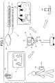
- the remote operation system 1 includes a mobile robot 10 and an operation terminal 100, and the mobile robot 10 and the operation terminal 100 communicate with each other through a communication network 200.
- the mobile robot 10 includes a head unit 11, a neck unit 12, a body unit 13, and a traveling unit 14.
- the head unit 11 is provided with a robot display unit 61, a robot speaker 63, and a robot microphone 64.
- the neck unit 12 causes the head unit 11 to perform a swing motion for swinging vertically and horizontally (a head-shaking motion) with respect to the body unit 13.
- the body unit 13 is provided with a robot camera 62 and a LiDAR 65.
- the robot camera 62 captures an image of surroundings of the mobile robot 10, and the LiDAR 65 detects a distance to an object present in the surroundings of the mobile robot 10 by laser irradiation.
- the LiDAR 65 corresponds to an object detection sensor.
- An operation screen including a monitor image transmitted from the mobile robot 10 is displayed on a terminal display unit 141 (touch panel) of the operation terminal 100.
- a user U of the remote operation system 1 visually recognizes the monitor image of the surroundings of the mobile robot 10 displayed on the operation screen to recognize the situation of a movement destination of the mobile robot 10. Then, the user U remotely operates the mobile robot 10 on the operation terminal 100 in accordance with the situation of the mobile robot 10.
- the mobile robot 10 is a so-called telepresence robot, and for example, moves inside a building 300 to participate in a conference at a conference place 301, or moves outdoors to a sightseeing spot 310 or a destination 320 such as a hotel.
- the robot display unit 61 of the mobile robot 10 displays a face image of the user U or an icon imitating the face of the user U. This configuration enables making people near the mobile robot 10 feel as if the user U itself were present at the movement destination of the mobile robot 10.
- the user U visually recognizes the image of the surroundings of the mobile robot 10 displayed on the operation terminal 100, and can have a feeling as if the user U itself were present at the movement destination of the mobile robot 10. Furthermore, the user U is able to communicate with a person or another robot present at the movement destination of the mobile robot 10 over a video call or a chat on the operation terminal 100.
- the mobile robot 10 acquires, through the communication network 200, information of the inside of a movement area of the mobile robot 10 from an area information server 210, and also acquires information of the mobile robot 10 or another robot from a robot management server 220.
- the mobile robot 10 includes, in addition to the above-described constituent elements, a robot communication unit 60, a robot controller 20, a global navigation satellite system (GNSS) sensor 66, a speed sensor 67, and an inclination sensor 68.
- GNSS global navigation satellite system
- the robot communication unit 60 communicates with the operation terminal 100 through the communication network 200. Note that in a situation in which the distance between the mobile robot 10 and the operation terminal 100 is short, the robot communication unit 60 may directly communicate with the operation terminal 100.
- the GNSS sensor 66 receives radio waves from a GNSS satellite, and detects the current location of the mobile robot 10.
- the speed sensor 67 detects a moving speed (traveling speed) of the mobile robot 10.
- the inclination sensor 68 detects an inclination angle of the mobile robot 10 with respect to the horizontal direction.
- the robot controller 20 is configured with a robot processor 30, a robot memory 50, an interface circuit, not illustrated, and the like.
- the robot memory 50 stores a robot control program 51, a map database (DB) 52, a building DB 53, and the like.
- DB map database
- a map of the movement area of the mobile robot 10 is recorded in the map DB 52.
- a floor layout and the like of a building present in the movement area of the mobile robot 10 is recorded in the building DB 53.
- the map DB 52 and the building DB 53 may be downloaded from the area information server 210 to the mobile robot 10.
- the robot control program 51 may be downloaded from the robot management server 220 to the mobile robot 10.
- the robot processor 30 reads and executes the robot control program 51 from the robot memory 50 so as to function as a screen display controller 31, a current location recognition unit 32, a moving situation recognition unit 33, a display mode switching unit 34, a surrounding target object recognition unit 35, a communication target selection reception unit 36, a communication controller 37, an obstacle recognition unit 38, an in-motion object recognition unit 39, a destination recognition unit 40, a movement route recognition unit 41, a display image range setting unit 42, a camera image-capturing range controller 43, a horizontal direction image acquisition unit 44, a user face image display controller 45, and a display layout change unit 46.
- the screen display controller 31 changes data of the operation screen to be transmitted to the operation terminal 100 in accordance with a stop display mode corresponding to a case where the mobile robot 10 is in a stopped state and a movement display mode corresponding to a case where the mobile robot 10 is in a moving state (traveling state), so as to control the operation screen to be displayed on the terminal display unit 141 of the operation terminal 100. Details of the display mode on the operation screen in each display mode will be described later.
- the current location recognition unit 32 recognizes the current location (latitude, longitude) of the mobile robot 10, based on a location detection signal output from the GNSS sensor 66.
- the moving situation recognition unit 33 recognizes the moving situation of the mobile robot 10, based on a change in the current location of the mobile robot 10 recognized by the current location recognition unit 32, a moving speed of the mobile robot 10 detected by the speed sensor 67, map data that has been acquired from the map DB 52, a building layout that has been acquired from the building DB 53, and the like.
- the current location recognition unit 32 matches a detected situation of a surrounding object by the LiDAR 65 with indoor layout data that has been acquired from the building DB 53, and recognizes the current location of the mobile robot 10.
- the display mode switching unit 34 switches the display mode of the operation screen on the display terminal 100 between the stop display mode and the movement display mode in response to a selection operation by the user U.
- the surrounding target object recognition unit 35 recognizes a person and another robot present in the surroundings of the mobile robot 10 each as a surrounding target object, based on the image captured by the robot camera 62, an object detection signal detected by the LiDAR 65, and a detected sound detected by the robot microphone 64.
- the robot communication unit 60 may receive an identification signal transmitted from a transmitter carried by a person or another robot, and may recognize a person or another robot present in the surroundings of the mobile robot 10.
- the communication target selection reception unit 36 receives a selection of a surrounding target object with whom the user U desires to communicate, in response to a selection operation on the operation screen by the user U.
- the communication controller 37 controls communication between the user U and the surrounding target object, the selection of which has been received by the communication target selection reception unit 36.
- the communication controller 37 enables a video call, a voice call, and a chat between the user U and the surrounding target object.
- the obstacle recognition unit 38 recognizes an obstacle present in the surroundings of the mobile robot 10, based on the image captured by the robot camera 62 and the object detection signal detected by the LiDAR 65.
- the in-motion object recognition unit 39 recognizes an object in motion in the surroundings of the mobile robot 10, based on an image captured by the robot camera 62, an object detection signal detected by the LiDAR 65, and a detected sound detected by the robot microphone 64.
- the object in motion includes a person and another robot except for the mobile robot 10.
- the "motion" includes an action of uttering a voice such as a speech, in addition to an action of moving its body.
- the destination recognition unit 40 recognizes a movement destination of the mobile robot 10 that has been set by the user U.
- the user U operates the operation terminal 100, and sets the destination of the mobile robot 10.
- the destination includes not only a final destination for which the mobile robot 10 is heading but also a stop point on its way to the final destination.
- the movement route recognition unit 41 recognizes a movement route of the mobile robot 10, based on the current location of the mobile robot 10 that has been recognized by the current location recognition unit 32, the destination of the mobile robot 10 that has been recognized by the destination recognition unit 40, and the map data that has been acquired from the map DB 52.
- the display image range setting unit 42 sets a range of the monitor image to be displayed on the operation screen of the operation terminal 100 in response to an operation by the user U.
- the camera image-capturing range controller 43 moves the mobile robot 10 so that all persons and other robots present in the surroundings of the mobile robot 10 are included in an image-capturing range of the robot camera 62.
- the robot camera 62 may be switched to the wide angle so that all persons and other robots present in the surroundings of the mobile robot 10 can be included in the image-capturing range of the robot camera 62.
- the horizontal direction image acquisition unit 44 performs a process of causing the imaging direction of the robot camera 62 to be the horizontal direction as illustrated in S3 and S4. This process enables acquisition of a captured image in the traveling direction of the mobile robot 10.
- the horizontal direction image acquisition unit 44 extracts an image in a range corresponding to the horizontal direction (a horizontal corresponding image) from an image facing either upward or downward that has been captured by the robot camera 62 in the situation of S1 and S2 so as to acquire a captured image in the traveling direction of the mobile robot 10.
- the user face image display controller 45 controls whether to cause the robot display unit 61 to display the face image of the user U in response to an operation on the operation terminal 100 by the user U.
- the face image of the user U may be a real-time image captured by a terminal camera 142 and transmitted to the mobile robot 10, or may be an image stored beforehand in the robot memory 50 of the mobile robot 10.
- the user face image display controller 45 displays an icon imitating the face of the user U on the robot display unit 61 in response to the operation of the user U, or displays neither the face image nor the icon imitating the face on the robot display unit 61.
- the display layout change unit 46 changes the layout of the operation screen to be displayed on the operation terminal 100 in response to the operation on the operation terminal 100 by the user U.
- the operation terminal 100 includes a terminal controller 110, a terminal communication unit 140, a terminal display unit 141, the terminal camera 142, a terminal microphone 143, and a terminal speaker 144.
- the operation terminal 100 may be a dedicated terminal for operating the mobile robot 10, or may be a general-purpose communication terminal such as a smartphone or a tablet terminal.
- the terminal communication unit 140 and the mobile robot 10 communicate with each other through the communication network 200 (see FIG. 1 ).
- the terminal display unit 141 is a touch panel, displays an operation screen corresponding to screen data output from the terminal controller 110, and outputs operation data corresponding to a touch operation of the user U to the terminal controller 110.
- the terminal camera 142 captures a face image and the like of the user U, and outputs data of the captured image to the terminal controller 110.
- the terminal microphone 143 detects sound of voices or the like of the user U, and outputs sound data to the terminal controller 110.
- the terminal speaker 144 receives sound data output from the terminal controller 110, and outputs sound of voices or the like of a communication partner with whom a call is being made via the mobile robot 10.
- a robot operation application program 131 for realizing the operation of the mobile robot 10 is stored in a terminal memory 130.
- a terminal processor 120 reads and executes the robot operation application program 131 so as to function as a robot operation screen controller 121 and a robot operation instruction controller 122.
- the robot operation screen controller 121 receives data of the operation screen for the mobile robot 10 transmitted from the mobile robot 10 via the terminal communication unit 140, and displays the operation screen on the terminal display unit 141.
- the data of the operation screen includes monitor image information based on an image captured by the robot camera 62.
- the robot operation instruction controller 122 recognizes an instruction content of the operation by the user U from an operation signal corresponding to a touch operation on the operation screen output from the terminal display unit 141, and transmits operation data indicating the instruction content of the operation to the mobile robot 10 via the terminal communication unit 140.
- the screen display controller 31 switches and controls the operation screen displayed on the operation terminal 100 between the operation screen in the stop display mode illustrated in FIGS. 7 to 9 and the display screen in the movement display mode illustrated in FIGS. 10 to 13 .
- an operation screen 510 includes a first sub screen 520 for displaying a monitor image that has been extracted from a captured image 500 of the surroundings of the mobile robot 10 captured by the robot camera 62, and a second sub screen 530 for operating the mobile robot 10.
- the second sub screen 530 is an area except for the first sub screen 520 of the operation screen 510.
- a mode changeover switch 531 for switching the display mode is displayed on the second sub screen 530.
- the operation screen 510 in FIG. 7 is an operation screen in the stop display mode corresponding to a case where the mobile robot 10 is in a stopped state, and thus a vertical shaking icon 532 for instructing the head unit 11 of the mobile robot 10 to shake vertically and a horizontal shaking icon 533 for instructing the head unit 11 to shake horizontally are displayed. Furthermore, communication icons 534 for conducting communication over a video call, a voice call, a chat, and the like, and a communication window 540 are displayed.
- the communication icons 534 include a voice call icon 534a for starting a voice call, a video call icon 534b for starting a video call, an option icon 534c for starting a chat or the like, and a call end icon 534d for ending the call.
- a voice call icon 534a for starting a voice call
- a video call icon 534b for starting a video call
- an option icon 534c for starting a chat or the like
- a call end icon 534d for ending the call.
- step S1 of FIG. 4 the display mode switching unit 34 recognizes an operation state of the mode changeover switch 531, based on the operation data transmitted from the operation terminal 100. Then, when the switching operation to a head-shaking mode is performed by the mode changeover switch 531, the display mode switching unit 34 advances the process to step S10 to set the stop display mode, and advances the process to step S4.
- step S3 determines whether the switching operation to a traveling mode on the mode changeover switch 531 has been performed. Then, when the switching operation to the traveling mode is performed, the display mode switching unit 34 advances the process to step S50. When the switching operation to the traveling mode is not performed, the display mode switching unit 34 advances the process to step S4. In step S4, the display mode switching unit 34 sets the display mode of the operation screen to the movement display mode.
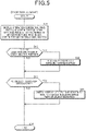
- step S11 of FIG. 5 the screen display controller 31 transmits, to the operation terminal 100, the screen data of the operation screen 510 in the stop display mode, and causes the operation screen 510 to be displayed on the terminal display unit 141 of the operation terminal 100.
- the operation screen 510 includes the first sub screen 520 for displaying the monitor image based on the image 500 captured by the robot camera 62, and the second sub screen 530 for displaying an operation unit for communication.
- FIG. 7 illustrates the captured image 500 and the operation screen 510 in a situation in which the mobile robot 10 is present in a conference place, and the captured image 500 includes image parts of conference participants.
- the camera image-capturing range controller 43 moves the mobile robot 10 to adjust the image-capturing range of the robot camera 62 so as to include the image parts of all persons participating in the conference and another robot. Note that, in a case where the robot camera 62 is provided with a function of changing the imaging direction or switching between the wide angle and the standard of the lens, the camera image-capturing range controller 43 also uses these functions to adjust the image-capturing range of the robot camera 62.
- the screen display controller 31 displays, on the first sub screen 520, a first monitor image 520a obtained by extracting the image parts of a range 501, which is set to include the image parts of all persons and another robot present at the conference place, from the image 500 captured by the robot camera 62.
- the user U visually recognizes the first sub screen 520, and is able to confirm the persons participating in the conference and another robot.
- next step S12 the communication target selection reception unit 36 determines whether the user U has performed a touch operation on any one of image parts 522 to 526 of the persons displayed on the first sub screen 520. Then, when the image part of any person is touched, the communication target selection reception unit 36 sets the person corresponding to the image part that has been touched as a communication target with the user U, and advances the process to step S20.
- the screen display controller 31 may display an enlarged image of the image part of the person that has been set as the communication target, on the first sub screen 520 or the second sub screen 530.
- FIG. 7 illustrates an example in which the screen display controller 31 displays the image 541 obtained by enlarging the image part of the person that has been set as the communication target, on the communication window 540 of the second sub screen 530.
- the communication controller 37 may establish communication between a communication terminal used by the person that has been set as the communication target and the operation terminal 100, so that the communication (voice call, chat, or the like) with the user U may be enabled only for the person that has been set as the communication target.
- step S20 the communication controller 37 controls the communication between the user U and the communication target over a voice call, a video call, or a chat in response to an operation on the communication icon 534 by the user U, and advances the process to step S13.
- step S13 the in-motion object recognition unit 39 searches for an object in motion present in the surroundings of the mobile robot 10, and advances the process to step S21 when recognizing the object in motion.
- step S21 as illustrated in FIG. 8 , the screen display controller 31 extracts an image part of a range 504 including an image part 503 of the object in motion from an image 502 captured by the robot camera 62. Then, a second monitor screen 520b obtained by enlarging the image part of the range 504 is displayed on the first sub screen 520. Accordingly, the user U is able to easily recognize the object in motion approaching the mobile robot 10.
- the screen display controller 31 may extract the image part of a range 505 including the image part 503 of the object in motion and the image parts of all persons participating in the conference from the image 502 captured by the robot camera 62. In this case, the screen display controller 31 displays a monitor image of the range 505 on the first sub screen 520. Accordingly, the user U is able to easily recognize the object in motion approaching the mobile robot 10, while visually recognizing the situations of all the persons participating in the conference.
- the screen display controller 31 determines the object in motion to be a target of the process in step S21 in accordance with a following determination condition sequentially from priority order 1, priority order 2, and priority order 3.
- priority orders are merely an example, and for example, the user U may operate the operation terminal 100 to customize the priority orders.
- step S51 of FIG. 6 the screen display controller 31 transmits, to the operation terminal 100, the screen data of the operation screen 510 in the movement display mode, and causes the operation screen 510 to be displayed on the terminal display unit 141 of the operation terminal 100.
- the operation screen 510 includes the first sub screen 520 for displaying a monitor image based on the image captured by the robot camera 62, and the second sub screen 530 for displaying an image for supporting an operation for moving the mobile robot 10.
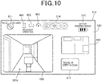
- FIG. 10 illustrates the operation screen 510 in a situation in which the mobile robot 10 is moving inside a building (indoors).
- a forward/backward movement icon for giving an instruction on a forward or backward movement of the mobile robot 10 and a leftward/rightward movement icon 602 for giving an instruction on a leftward or rightward movement are displayed.
- a speed meter 603 that displays a moving speed of the mobile robot 10 is displayed.
- a floor layout diagram 610 of the building in which the mobile robot 10 is moving is displayed.
- step S52 the obstacle recognition unit 38 searches for an obstacle present in the surroundings of the mobile robot 10. Then, the obstacle recognition unit 38 advances the process to step S60 when recognizing the obstacle, or advances the process to step S53 when not recognizing the obstacle.
- step S60 as illustrated in FIG. 6 , the screen display controller 31 displays an obstacle notification window 611 for providing notification of the presence of an obstacle on the second sub screen 530.
- an attention message here, a message "There is a step ahead"
- an image of an obstacle, or the like is displayed.
- next step S53 the screen display controller 31 determines whether a selection operation of selecting the image part displayed on the first sub screen 520 has been performed in a state where the moving speed of the mobile robot 10 is a low-speed determination speed (for example, the moving speed is set to several kilometers per hour). Then, the screen display controller 31 advances the process to step S61, when the selection operation of selecting the image part is performed, or advances the process to step S54, when the selection operation of selecting the image part is not performed.
- a low-speed determination speed for example, the moving speed is set to several kilometers per hour
- step S61 as illustrated in FIG. 11 , when an image part 612 (here, an image part of a floor guide panel) of the first sub screen 520 is selected, the screen display controller 31 displays, on the second sub screen 530, an enlarged window 620 obtained by enlarging the image part 612. Accordingly, while checking the front of the mobile robot 10 in a wide range on the first sub screen 520, the user U is able to visually recognize details of a target object that the user U desires to confirm on the enlarged window 620 of the second sub screen 530.
- an image part 612 here, an image part of a floor guide panel
- step S54 the moving situation recognition unit 33 determines whether the mobile robot 10 is present in a sightseeing spot. Then, the moving situation recognition unit 33 advances the process to step S62 in a case where the mobile robot 10 is present in the sightseeing spot, or advances the process to step S55 in a case where the mobile robot 10 is not located in the sightseeing spot.
- step S62 the screen display controller 31 displays the operation screen 510 including the first sub screen 520 for displaying a captured image 520e of the surroundings of the mobile robot 10, and the second sub screen 530 for displaying a map 700 of the sightseeing spot (here, a zoo). Furthermore, the screen display controller 31 displays additional information 701 for displaying additional information at the present location of the mobile robot 10 or in the vicinity of the mobile robot 10.
- the screen display controller 31 also displays an obstacle notification window 702 in the process of step S60.
- step S55 the moving situation recognition unit 33 determines whether the moving speed of the mobile robot 10 is equal to or higher than a high-speed determination speed (for example, the speed is set to several tens of kilometers per hour). Then, the moving situation recognition unit 33 advances the process to step S63, in a case where the moving speed of the mobile robot 10 is equal to or higher than the high-speed determination speed, or advances the process to step S56, in a case where the moving speed of the mobile robot 10 is lower than the high-speed determination speed.
- a high-speed determination speed for example, the speed is set to several tens of kilometers per hour.
- step S63 the screen display controller 31 displays the operation screen 510 including the first sub screen 520 for displaying a captured image 520f of the front of the mobile robot 10, and the second sub screen 530 for displaying a route guidance window 800 indicating a route Rt from a current location S of the mobile robot 10 to a destination G on a map of the movement area of the mobile robot 10.
- the display of the route guidance window 800 enables support for the user U to move the mobile robot 10 to the destination.
- the screen display controller 31 displays a predicted arrival time 801 at the destination on the second sub screen 530.
- the screen display controller 31 displays an obstacle window 802 on the second sub screen 530 in the process of step S60.
- the obstacle window 802 an image part of a pedestrian that has been recognized as an obstacle is displayed in a highlighted manner by a frame 802a.
- the screen display controller 31 displays a communication icon 514 to be darker (in a different display mode) than a frontward/backward movement icon 601 and a leftward/rightward movement icon 602 that can be operated. Accordingly, the user U is made to understand that the operation of the communication icon 514 is disabled.
- a different display mode another display mode, such as displaying an operable icon in color and displaying an inoperable icon in gray scale, may be used.
- the display mode switching unit 34 switches between the stop display mode and the movement display mode in response to the operation of the mode changeover switch 531 by the user U in the process of the flowchart illustrated in FIG. 4 .
- the stop display mode and the movement display mode may be switched in accordance with the moving situation of the mobile robot 10 recognized by the moving situation recognition unit 33. For example, while the mobile robot 10 is in the stop state for a predetermined time or more, the mode may be switched to the stop display mode. In addition, while the mobile robot is moving at a predetermined speed or higher, the mode may be switched to the movement display mode.
- the display of the first sub screen 520 is switched from the first monitor screen 520a that does not include the image part of the object in motion to the second monitor screens 520b and 520c that include the image part of the object in motion.
- the second monitor screens 520b and 520c including the image part of the object in motion may be displayed on the second sub screen 530 without changing the display of the first sub screen 520.
- the first sub screen 520 may be switched from the first monitor screen to the second monitor screen in the stop display mode, and the second monitor screen may be displayed on the second sub screen 530 in the movement display mode.
- the communication target selection reception unit 36 sets such a person corresponding to the image part subjected to the touch operation as a communication target.
- identification information a name, an ID, and the like
- a person or a robot corresponding to an image part displayed on the first sub screen 520 may be displayed in a list on the first sub screen 520, so that a communication target can be selected by a touch operation on the identification information displayed in the list.
- the display of the operation screen 510 is controlled in the process of the screen display controller 31 to the user face image display controller 45 by the robot processor 30 of the mobile robot 10.
- all or a part of the screen display controller 31 to the user face image display controller 45 may be configured with the terminal processor 120 of the operation terminal 100.
- the terminal processor 120 controls the operation screen 510 displayed on the terminal display unit 141, based on the image captured by the robot camera 62, the data of the sound detected by the robot microphone 64, the data of the object detected by the LiDAR 65, and the like, which are transmitted from the mobile robot 10.
- all or a part of the screen display controller 31 to the user face image display controller 45 may be configured with the robot management server 220.
- the robot management server 220 communicates with the mobile robot 10 and the operation terminal 100, receives the image captured by the robot camera 62, operation data on the operation terminal 100, and the like, and controls display of the terminal display unit 141 of the operation terminal 100.
- the current location recognition unit 32 may recognize that the mobile robot 10 is located inside a room, based on the map DB 52 or the building DB 53. Then, in a state where the current location recognition unit 32 recognizes that the mobile robot 10 is located inside the room, when an object entering the room is detected, based on an image captured by the robot camera 62, an object detection signal detected by the LiDAR 65, a sound detected by the robot microphone 64, and the like, the in-motion object recognition unit 39 may recognize the object as an object in motion.
- FIGS. 2 and 3 are schematic diagrams illustrating the configurations of the mobile robot 10 and the operation terminal 100 in a separated manner in accordance with a main processing content in order to facilitate understanding of the present invention.
- the configurations of the mobile robot 10 and the operation terminal 100 may be made in another separated manner.
- the process of each constituent element may be performed by one hardware unit, or may be performed by a plurality of hardware units.
- the process of each constituent element illustrated in FIGS. 4 to 6 may be performed by one program, or may be performed by a plurality of programs.
- the configuration in which the moving situation recognition unit 33 recognizes the moving speed of the mobile robot 10 corresponds to a moving speed recognition unit in the present disclosure.
- the configuration in which the current location recognition unit 32 recognizes whether the mobile robot is present indoors or outdoors corresponds to an indoor and outdoor location recognition unit in the present disclosure.
- the configuration in which the screen display controller 31 causes the robot communication unit 60 to transmit the data of the operation screen to the operation terminal 100 corresponds to a screen data transmission unit in the present disclosure.
- the configuration in which the terminal processor 120 causes the terminal communication unit 140 to receive the monitor image information based on the captured image of the surroundings of the mobile robot 10 transmitted from the mobile robot 10 corresponds to a monitor image information acquisition unit in the present disclosure.
- a remote operation system includes: a mobile robot; and an operation terminal configured to communicate with the mobile robot with each other, the mobile robot including a camera configured to capture an image of surroundings of the mobile robot, and transmitting, to the operation terminal, monitor image information based on a captured image by the camera, the operation terminal including a terminal display unit, receiving the monitor image information, and displaying, on the terminal display unit, an operation screen including a monitor image based on the captured image, in which the remote operation system includes a screen display controller configured to display the operation screen on the terminal display unit, the operation screen including a first sub screen for displaying the monitor image and a second sub screen different from the first sub screen, and configured to change a display content of the second sub screen in accordance with a predetermined display mode.
- the second sub screen different from the first sub screen is displayed on the operation screen displayed on the terminal display unit, so that the remote operation of the mobile robot by the user in accordance with the surrounding situation of the mobile robot can be supported.
- the remote operation system in Item 2 it is possible to support communication between the user of the operation terminal and the surrounding target object (either a person or another robot) that has been selected by the user.
- the user of the operation terminal is able to select a communication target with reference to the list of persons or other robots present in the surroundings of the mobile robot.
- Item 4 The remote operation system as described in Item 2 or Item 3, in which the communication target selection reception unit receives the selection of the surrounding target object in response to the selection operation for an image part of the surrounding target object displayed on the first sub screen.
- the user of the operation terminal is able to confirm the image of the surrounding target object and select the communication target.
- oneto-one communication with a specific surrounding target object is enabled, while the confirmation of a communication partner is facilitated in an enlarged image.
- (Item 6) The remote operation system as described in one of Item 2 to Item 5, in which the surrounding target object recognition unit recognizes either the surrounding target object registered beforehand or the surrounding target object present within a predetermined distance from the mobile robot, from the surrounding target object present in the surroundings of the mobile robot.
- the remote operation system in Item 6 by limiting the communication target to a surrounding target object registered beforehand or a surrounding target object located within a predetermined distance from the mobile robot, the user is able to easily select a communication partner.
- (Item 7) The remote operation system as described in one of Item 1 to Item 6, in which a movement display mode corresponding to a situation in which the mobile robot is in a moving process is set as the display mode, and in the movement display mode, the screen display controller displays, on the second sub screen, operation support information for supporting an operation for the mobile robot in the moving process.
- the operation screen including the first sub screen for displaying the monitor image and the second sub screen that is another one for supporting the operation for the mobile robot in the moving process is displayed, so that the operation of the mobile robot by the user can be facilitated.
- the operation screen including the first sub screen and the second sub screen for respectively displaying the image parts corresponding to the different image-capturing ranges is displayed on the terminal display unit, so that the user is able to easily recognize the surrounding situation of the mobile robot.
- the remote operation system as described in Item 8, further includes an obstacle recognition unit configured to recognize an obstacle present in the surroundings of the mobile robot, in which in the movement display mode, the screen display controller displays, on the second sub screen, the image part of the second image-capturing range including the obstacle by highlighting an image part of the obstacle.
- an obstacle recognition unit configured to recognize an obstacle present in the surroundings of the mobile robot, in which in the movement display mode, the screen display controller displays, on the second sub screen, the image part of the second image-capturing range including the obstacle by highlighting an image part of the obstacle.
- the remote operation system in Item 10 by displaying the map of the movement area on the second sub screen, the user is able to easily recognize the movement destination of the mobile robot.
- the remote operation system in Item 11 by displaying the area additional information on the second sub screen, the user is able to easily select a point to stop by in the moving process of the mobile robot.
- the remote operation system as described in Item 11 or Item 12, further includes a current location recognition unit configured to recognize a current location of the mobile robot, in which in the movement display mode, when the current location recognition unit recognizes that the mobile robot is located in a registered area registered as a sightseeing area, the screen display controller displays, on the second sub screen, the area additional information associated with the registered area as the operation support information.
- the situation related to the location where the mobile robot is located can be provided to the user by displaying the second sub screen.
- the remote operation system as described in one of Item 11 to Item 13, further includes a moving speed recognition unit configured to recognize a moving speed of the mobile robot, in which when the moving speed of the mobile robot is equal to or lower than a predetermined low-speed determination speed, the screen display controller displays, on the second sub screen, the area additional information as the operation support information.
- a moving speed recognition unit configured to recognize a moving speed of the mobile robot, in which when the moving speed of the mobile robot is equal to or lower than a predetermined low-speed determination speed, the screen display controller displays, on the second sub screen, the area additional information as the operation support information.
- the area additional information can be provided to the user, only when the moving speed of the mobile robot is relatively low.
- the remote operation system as described in one of Item 7 to Item 14, further includes: a current location recognition unit configured to recognize a current location of the mobile robot; a destination recognition unit configured to recognize a destination of the mobile robot; and a movement route recognition unit configured to recognize a movement route from the current location to the destination, and in the movement display mode, the screen display controller displays, on the second sub screen, navigation information for navigating a movement along the movement route from the current location to the destination as the operation support information.
- the remote operation system in Item 15 by displaying the navigation information on the second sub screen, the user is able to easily operate the mobile robot to the destination.
- the remote operation system as described in Item 15, further includes a moving speed recognition unit configured to recognize a moving speed of the mobile robot, and when the moving speed of the mobile robot is equal to or higher than a predetermined high-speed determination speed, the screen display controller displays the navigation information on the second sub screen.
- a moving speed recognition unit configured to recognize a moving speed of the mobile robot, and when the moving speed of the mobile robot is equal to or higher than a predetermined high-speed determination speed, the screen display controller displays the navigation information on the second sub screen.
- the navigation information is displayed on the second sub screen to support the operation of the mobile robot by the user.
- a user face image display controller configured to, in the movement display mode, prohibit a face image of a user of the operation terminal from being displayed on the robot display unit, or configured to switch a display on the robot display unit to a display of a predetermined substitute icon.
- the remote operation system in Item 17 in a case where it is assumed that the mobile robot is moving and the user is unlikely to communicate with either a person or another robot present in the surroundings of the mobile robot, it is possible to prohibit the face image of the user from being displayed on the display unit of the robot or to switch to the display of the substitute icon.
- the remote operation system as described in one of Item 1 to Item 17, further includes a display mode switching unit configured to switch the display mode in response to an operation on the operation terminal by a user.
- the display mode of the operation terminal can be switched to a display mode that the user desires.
- the remote operation system as described in one of Item 1 to Item 17, further includes: an indoor and outdoor location recognition unit configured to recognize whether the mobile robot is present indoors or outdoors; and a display mode switching unit configured to switch the display mode in accordance with whether the mobile robot is present indoors or outdoors.
- the remote operation system in Item 19 it is possible to switch the display mode in accordance with the environment in which the mobile robot is present in accordance with whether the mobile robot is present indoors or outdoors.
- the remote operation system as described in one of Item 1 to Item 19, further includes a display layout change unit configured to change a display layout of the operation screen in response to an operation on the operation terminal by a user.
- the display layout of the operation screen can be set to a layout in accordance with the user's desire.
- (Item 21) The remote operation system as described in one of Item 1 to Item 20, in which the terminal display unit is a touch panel, and the screen display controller displays a first operation icon, for which a touch operation is disabled in accordance with the predetermined display mode, in a display mode different from a display mode of a second operation icon for which the touch operation is enabled, out of operation icons displayed on the operation screen.
- a mobile robot including: a camera configured to capture an image of surroundings; a robot communication unit configured to communicate with an operation terminal; a screen display controller configured to set an operation screen to be displayed on a terminal display unit of the operation terminal; and a screen data transmission unit configured to cause the robot communication unit to transmit, to the operation terminal, data of the operation screen that has been set by the screen display controller, and the screen display controller sets the operation screen including a first sub screen for displaying a monitor image based on a captured image by the camera, and a second sub screen different from the first sub screen, and changes a display content of the second sub screen in accordance with a predetermined display mode.
- the mobile robot in Item 22 by transmitting, to the terminal display unit, the data of the operation screen for displaying the second sub screen different from the first sub screen, in addition to the first sub screen for displaying the monitor image of the surroundings of the mobile robot, it is possible to support the remote operation of the mobile robot by the user in accordance with the surrounding situation of the mobile robot.
- An operation terminal for remotely operating a mobile robot including: a terminal display unit; a terminal communication unit configured to communicate with the mobile robot with each other; a monitor image information acquisition unit configured to receive, via the terminal communication unit, monitor image information based on a captured image of surroundings of the mobile robot, the monitor image information being transmitted from the mobile robot; and a screen display controller configured to display, on the terminal display unit, an operation screen including a first sub screen for displaying a monitor image based on the monitor image information and a second sub screen different from the first sub screen, and configured to change a display content of the second sub screen in accordance with a predetermined display mode.
- the monitor image information transmitted from the mobile robot is received, and, in addition to the first sub screen for displaying the monitor image of the surroundings of the mobile robot, the second sub screen different from the first sub screen is displayed on the operation screen displayed on the terminal display unit, so that the remote operation of the mobile robot by the user in accordance with the surrounding situation of the mobile robot can be supported.
Landscapes
- Engineering & Computer Science (AREA)
- Physics & Mathematics (AREA)
- Radar, Positioning & Navigation (AREA)
- Remote Sensing (AREA)
- General Physics & Mathematics (AREA)
- Automation & Control Theory (AREA)
- Aviation & Aerospace Engineering (AREA)
- General Engineering & Computer Science (AREA)
- Theoretical Computer Science (AREA)
- Human Computer Interaction (AREA)
- Electromagnetism (AREA)
- Robotics (AREA)
- Mechanical Engineering (AREA)
- Health & Medical Sciences (AREA)
- General Health & Medical Sciences (AREA)
- Computing Systems (AREA)
- Mathematical Physics (AREA)
- Audiology, Speech & Language Pathology (AREA)
- Computer Vision & Pattern Recognition (AREA)
- Multimedia (AREA)
- Control Of Position, Course, Altitude, Or Attitude Of Moving Bodies (AREA)
- Telephonic Communication Services (AREA)
- Manipulator (AREA)
Abstract
Description
- The present invention relates to a remote operation system, a robot, and an operation terminal.
- There has been conventionally proposed a system in which a user remotely operates a mobile robot including a camera using an operation terminal (see, for example,
JP 2019-62293 A - According to the above system, an image captured by the camera of the mobile robot is transmitted to the operation terminal, and the user is able to operate the mobile robot while recognizing a surrounding image of a movement destination of the mobile robot displayed on the operation terminal.
- In the above-described remote operation system of the mobile robot, the user has to recognize the situation in which the mobile robot is located from the surrounding image of the mobile robot and perform an appropriate operation in accordance with the situation.
- The present invention has been made in view of the above circumstances, and has an object to provide a remote operation system, a robot, and an operation terminal, which are capable of supporting a user's remote operation of the mobile robot in accordance with a surrounding situation of the mobile robot.
- As a first aspect for achieving the above object, there is a remote operation system including: a mobile robot; and an operation terminal configured to communicate with the mobile robot with each other, the mobile robot including a camera configured to capture an image of surroundings of the mobile robot, and transmitting, to the operation terminal, monitor image information based on a captured image by the camera, the operation terminal including a terminal display unit, receiving the monitor image information, and displaying, on the terminal display unit, an operation screen including a monitor image based on the captured image, in which the remote operation system includes a screen display controller configured to display the operation screen on the terminal display unit, the operation screen including a first sub screen for displaying the monitor image and a second sub screen different from the first sub screen, and configured to change a display content of the second sub screen in accordance with a predetermined display mode.
- In the above remote operation system, a configuration may be made such that a stop display mode corresponding to a situation in which the mobile robot is stopped is set as the display mode, the above remote operation system further includes: a surrounding target object recognition unit configured to recognize a surrounding target object that is either a person or another robot present in the surroundings of the mobile robot; and a communication target selection reception unit configured to receive a selection operation for the surrounding target object, and in the stop display mode, the screen display controller displays, on the second sub screen, an operation unit for supporting communication with the surrounding target object, selection of which has been received by the communication target selection reception unit.
- In the above remote operation system, a configuration may be made such that in the stop display mode, the screen display controller displays, on the second sub screen, a list of identification information of a plurality of the surrounding target objects, and the communication target selection reception unit receives the selection of the surrounding target object in response to the selection operation for the list of the identification information that has been displayed.
- In the above remote operation system, a configuration may be made such that the communication target selection reception unit receives the selection of the surrounding target object in response to the selection operation for an image part of the surrounding target object displayed on the first sub screen.
- In the above remote operation system, a configuration may be made such that the screen display controller displays, on either the first sub screen or the second sub screen, an image obtained by enlarging the image part of the surrounding target object, the selection of which has been received by the communication target selection reception unit, and the above remote operation system further includes a communication controller configured to enable the communication with only the surrounding target object, the selection of which has been received by the communication target selection reception unit.
- In the above remote operation system, a configuration may be made such that the surrounding target object recognition unit recognizes either the surrounding target object registered beforehand or the surrounding target object present within a predetermined distance from the mobile robot, from the surrounding target object present in the surroundings of the mobile robot.
- In the above remote operation system, a configuration may be made such that a movement display mode corresponding to a situation in which the mobile robot is in a moving process is set as the display mode, and in the movement display mode, the screen display controller displays, on the second sub screen, operation support information for supporting an operation for the mobile robot in the moving process.
- In the above remote operation system, a configuration may be made such that in the movement display mode, the screen display controller displays, on the first sub screen, an image part of a first image-capturing range in the captured image by the camera, and also displays, on the second sub screen, an image part of a second image-capturing range different from the first image-capturing range as the operation support information.
- In the above remote operation system, a configuration may be made to further include an obstacle recognition unit configured to recognize an obstacle present in the surroundings of the mobile robot, and in the movement display mode, the screen display controller displays, on the second sub screen, the image part of the second image-capturing range including the obstacle by highlighting an image part of the obstacle.
- In the above remote operation system, a configuration may be made such that in the movement display mode, the screen display controller displays, on the second sub screen, a map of a movement area of the mobile robot as the operation support information.
- In the above remote operation system, a configuration may be made such that in the movement display mode, the screen display controller displays, on the second sub screen, area additional information as the operation support information, the area additional information being information regarding at least one of a sightseeing spot present in the movement area, a facility present in the movement area, and an event performed in the movement area.
- In the above remote operation system, a configuration may be made such that when the selection operation for a specific location displayed on the map is performed, the screen display controller displays, on the second sub screen, the area additional information associated with the specific location as the operation support information.
- In the above remote operation system, a configuration may be made to further include a current location recognition unit configured to recognize a current location of the mobile robot, and in the movement display mode, when the current location recognition unit recognizes that the mobile robot is located in a registered area registered as a sightseeing area, the screen display controller displays, on the second sub screen, the area additional information associated with the registered area as the operation support information.
- In the above remote operation system, a configuration may be made to further include a moving speed recognition unit configured to recognize a moving speed of the mobile robot, and when the moving speed of the mobile robot is equal to or lower than a predetermined low-speed determination speed, the screen display controller displays, on the second sub screen, the area additional information as the operation support information.
- In the above remote operation system, a configuration may be made to further include: a current location recognition unit configured to recognize a current location of the mobile robot; a destination recognition unit configured to recognize a destination of the mobile robot; and a movement route recognition unit configured to recognize a movement route from the current location to the destination, and in the movement display mode, the screen display controller displays, on the second sub screen, navigation information for navigating a movement along the movement route from the current location to the destination as the operation support information.
- In the above remote operation system, a configuration may be made to further include a moving speed recognition unit configured to recognize a moving speed of the mobile robot, and when the moving speed of the mobile robot is equal to or higher than a predetermined speed, the screen display controller displays the navigation information on the second sub screen.
- In the above remote operation system, a configuration may be made such that the mobile robot includes a robot display unit, and the above remote operation system further includes a user face image display controller configured to, in the movement display mode, prohibit a face image of a user of the operation terminal from being displayed on the robot display unit, or configured to switch a display on the robot display unit to a display of a predetermined substitute icon.
- In the above remote operation system, a configuration may be made to further include a display mode switching unit configured to switch the display mode in response to an operation on the operation terminal by a user.
- In the above remote operation system, a configuration may be made to further include an indoor and outdoor location recognition unit configured to recognize whether the mobile robot is present indoors or outdoors; and a display mode switching unit configured to switch the display mode in accordance with whether the mobile robot is present indoors or outdoors.
- In the above remote operation system, a configuration may be made to further include a display layout change unit configured to change a display layout of the operation screen in response to an operation on the operation terminal by a user.
- In the above remote operation system, a configuration may be made such that the terminal display unit is a touch panel, and the screen display controller displays a first operation icon, for which a touch operation is disabled in accordance with the predetermined display mode, in a display mode different from a display mode of a second operation icon for which the touch operation is enabled, out of operation icons displayed on the operation screen.
- As a second aspect for achieving the above object, there is a mobile robot including a camera configured to capture an image of surroundings; a robot communication unit configured to communicate with an operation terminal; a screen display controller configured to set an operation screen to be displayed on a terminal display unit of the operation terminal; and a screen data transmission unit configured to cause the robot communication unit to transmit, to the operation terminal, data of the operation screen that has been set by the screen display controller, and the screen display controller sets the operation screen including a first sub screen for displaying a monitor image based on a captured image by the camera, and a second sub screen different from the first sub screen, and changes a display content of the second sub screen in accordance with a predetermined display mode.
- As a third aspect for achieving the above object, there is an operation terminal for remotely operating a mobile robot, the operation terminal including: a terminal display unit; a terminal communication unit configured to communicate with the mobile robot with each other; a monitor image information acquisition unit configured to receive, via the terminal communication unit, monitor image information based on a captured image of surroundings of the mobile robot, the monitor image information being transmitted from the mobile robot; and a screen display controller configured to display, on the terminal display unit, an operation screen including a first sub screen for displaying a monitor image based on the monitor image information and a second sub screen different from the first sub screen, and configured to change a display content of the second sub screen in accordance with a predetermined display mode.
- According to the above remote operation system, by displaying, on the operation screen to be displayed on the terminal display unit, the first sub screen for displaying the monitor image of the surroundings of the mobile robot as well as the second sub screen that is different from the first sub screen, the remote operation for the mobile robot by the user can be supported in accordance with the surrounding situation of the mobile robot.
-
-
FIG. 1 is an explanatory diagram of a configuration of a remote operation system; -
FIG. 2 is a configuration diagram of a mobile robot; -
FIG. 3 is a configuration diagram of an operation terminal; -
FIG. 4 is a flowchart of a switching process of an operation screen in accordance with a display mode; -
FIG. 5 is a flowchart of a display process of the operation screen in a stop display mode; -
FIG. 6 is a flowchart of a display process of the operation screen in a movement display mode; -
FIG. 7 is an explanatory diagram of a display mode of the operation screen in a situation in which the mobile robot is present in a conference place; -
FIG. 8 is an explanatory diagram of a display mode of the operation screen in a situation in which a new person is added to a conference place; -
FIG. 9 is an explanatory diagram of another display mode of the operation screen in the situation in which the new person is added to the conference place; -
FIG. 10 is an explanatory diagram of a display mode of the operation screen in a situation in which the mobile robot is moving indoors; -
FIG. 11 is an explanatory diagram of a mode in which a part of a monitor image is enlarged and displayed; -
FIG. 12 is an explanatory diagram of the operation screen in a situation in which the mobile robot is moving in a sightseeing spot; -
FIG. 13 is an explanatory diagram of the operation screen in a situation in which the mobile robot is moving on an outdoor road; and -
FIG. 14 is an explanatory diagram in a mode in which an imaging direction of a camera is controlled to a horizontal direction in a case where the mobile robot is moving on a slope. - A
remote operation system 1 in the present embodiment will be described with reference toFIG. 1 . Theremote operation system 1 includes amobile robot 10 and anoperation terminal 100, and themobile robot 10 and theoperation terminal 100 communicate with each other through acommunication network 200. Themobile robot 10 includes ahead unit 11, aneck unit 12, abody unit 13, and atraveling unit 14. - The
head unit 11 is provided with arobot display unit 61, arobot speaker 63, and arobot microphone 64. Theneck unit 12 causes thehead unit 11 to perform a swing motion for swinging vertically and horizontally (a head-shaking motion) with respect to thebody unit 13. Thebody unit 13 is provided with arobot camera 62 and a LiDAR 65. Therobot camera 62 captures an image of surroundings of themobile robot 10, and the LiDAR 65 detects a distance to an object present in the surroundings of themobile robot 10 by laser irradiation. The LiDAR 65 corresponds to an object detection sensor. - An operation screen including a monitor image transmitted from the
mobile robot 10 is displayed on a terminal display unit 141 (touch panel) of theoperation terminal 100. A user U of theremote operation system 1 visually recognizes the monitor image of the surroundings of themobile robot 10 displayed on the operation screen to recognize the situation of a movement destination of themobile robot 10. Then, the user U remotely operates themobile robot 10 on theoperation terminal 100 in accordance with the situation of themobile robot 10. - The
mobile robot 10 is a so-called telepresence robot, and for example, moves inside abuilding 300 to participate in a conference at aconference place 301, or moves outdoors to asightseeing spot 310 or adestination 320 such as a hotel. Therobot display unit 61 of themobile robot 10 displays a face image of the user U or an icon imitating the face of the user U. This configuration enables making people near themobile robot 10 feel as if the user U itself were present at the movement destination of themobile robot 10. - In addition, the user U visually recognizes the image of the surroundings of the
mobile robot 10 displayed on theoperation terminal 100, and can have a feeling as if the user U itself were present at the movement destination of themobile robot 10. Furthermore, the user U is able to communicate with a person or another robot present at the movement destination of themobile robot 10 over a video call or a chat on theoperation terminal 100. - The
mobile robot 10 acquires, through thecommunication network 200, information of the inside of a movement area of themobile robot 10 from anarea information server 210, and also acquires information of themobile robot 10 or another robot from arobot management server 220. - A configuration of the
mobile robot 10 will be described with reference toFIG. 2 . Themobile robot 10 includes, in addition to the above-described constituent elements, arobot communication unit 60, arobot controller 20, a global navigation satellite system (GNSS)sensor 66, aspeed sensor 67, and aninclination sensor 68. - The
robot communication unit 60 communicates with theoperation terminal 100 through thecommunication network 200. Note that in a situation in which the distance between themobile robot 10 and theoperation terminal 100 is short, therobot communication unit 60 may directly communicate with theoperation terminal 100. TheGNSS sensor 66 receives radio waves from a GNSS satellite, and detects the current location of themobile robot 10. Thespeed sensor 67 detects a moving speed (traveling speed) of themobile robot 10. Theinclination sensor 68 detects an inclination angle of themobile robot 10 with respect to the horizontal direction. - The
robot controller 20 is configured with arobot processor 30, arobot memory 50, an interface circuit, not illustrated, and the like. Therobot memory 50 stores arobot control program 51, a map database (DB) 52, abuilding DB 53, and the like. A map of the movement area of themobile robot 10 is recorded in themap DB 52. A floor layout and the like of a building present in the movement area of themobile robot 10 is recorded in thebuilding DB 53. - The
map DB 52 and thebuilding DB 53 may be downloaded from thearea information server 210 to themobile robot 10. Therobot control program 51 may be downloaded from therobot management server 220 to themobile robot 10. - The
robot processor 30 reads and executes therobot control program 51 from therobot memory 50 so as to function as ascreen display controller 31, a currentlocation recognition unit 32, a movingsituation recognition unit 33, a displaymode switching unit 34, a surrounding targetobject recognition unit 35, a communication targetselection reception unit 36, acommunication controller 37, anobstacle recognition unit 38, an in-motionobject recognition unit 39, adestination recognition unit 40, a movementroute recognition unit 41, a display imagerange setting unit 42, a camera image-capturing range controller 43, a horizontal directionimage acquisition unit 44, a user faceimage display controller 45, and a displaylayout change unit 46. - The
screen display controller 31 changes data of the operation screen to be transmitted to theoperation terminal 100 in accordance with a stop display mode corresponding to a case where themobile robot 10 is in a stopped state and a movement display mode corresponding to a case where themobile robot 10 is in a moving state (traveling state), so as to control the operation screen to be displayed on theterminal display unit 141 of theoperation terminal 100. Details of the display mode on the operation screen in each display mode will be described later. - The current
location recognition unit 32 recognizes the current location (latitude, longitude) of themobile robot 10, based on a location detection signal output from theGNSS sensor 66. The movingsituation recognition unit 33 recognizes the moving situation of themobile robot 10, based on a change in the current location of themobile robot 10 recognized by the currentlocation recognition unit 32, a moving speed of themobile robot 10 detected by thespeed sensor 67, map data that has been acquired from themap DB 52, a building layout that has been acquired from thebuilding DB 53, and the like. In a case where themobile robot 10 is located indoors, the currentlocation recognition unit 32 matches a detected situation of a surrounding object by theLiDAR 65 with indoor layout data that has been acquired from thebuilding DB 53, and recognizes the current location of themobile robot 10. - The display
mode switching unit 34 switches the display mode of the operation screen on thedisplay terminal 100 between the stop display mode and the movement display mode in response to a selection operation by the user U. The surrounding targetobject recognition unit 35 recognizes a person and another robot present in the surroundings of themobile robot 10 each as a surrounding target object, based on the image captured by therobot camera 62, an object detection signal detected by theLiDAR 65, and a detected sound detected by therobot microphone 64. Note that therobot communication unit 60 may receive an identification signal transmitted from a transmitter carried by a person or another robot, and may recognize a person or another robot present in the surroundings of themobile robot 10. - The communication target
selection reception unit 36 receives a selection of a surrounding target object with whom the user U desires to communicate, in response to a selection operation on the operation screen by the user U. Thecommunication controller 37 controls communication between the user U and the surrounding target object, the selection of which has been received by the communication targetselection reception unit 36. Thecommunication controller 37 enables a video call, a voice call, and a chat between the user U and the surrounding target object. - The
obstacle recognition unit 38 recognizes an obstacle present in the surroundings of themobile robot 10, based on the image captured by therobot camera 62 and the object detection signal detected by theLiDAR 65. The in-motionobject recognition unit 39 recognizes an object in motion in the surroundings of themobile robot 10, based on an image captured by therobot camera 62, an object detection signal detected by theLiDAR 65, and a detected sound detected by therobot microphone 64. The object in motion includes a person and another robot except for themobile robot 10. Here, the "motion" includes an action of uttering a voice such as a speech, in addition to an action of moving its body. - The
destination recognition unit 40 recognizes a movement destination of themobile robot 10 that has been set by the user U. The user U operates theoperation terminal 100, and sets the destination of themobile robot 10. Here, the destination includes not only a final destination for which themobile robot 10 is heading but also a stop point on its way to the final destination. - The movement
route recognition unit 41 recognizes a movement route of themobile robot 10, based on the current location of themobile robot 10 that has been recognized by the currentlocation recognition unit 32, the destination of themobile robot 10 that has been recognized by thedestination recognition unit 40, and the map data that has been acquired from themap DB 52. The display imagerange setting unit 42 sets a range of the monitor image to be displayed on the operation screen of theoperation terminal 100 in response to an operation by the user U. - The camera image-
capturing range controller 43 moves themobile robot 10 so that all persons and other robots present in the surroundings of themobile robot 10 are included in an image-capturing range of therobot camera 62. Note that, in a case where therobot camera 62 is configured to be switchable between a wide angle and a telescope, therobot camera 62 may be switched to the wide angle so that all persons and other robots present in the surroundings of themobile robot 10 can be included in the image-capturing range of therobot camera 62. - In a case where the
robot camera 62 has a function of changing an imaging direction, in a situation in which themobile robot 10 is located on a slope as illustrated in S1 and S2 ofFIG. 14 and therobot camera 62 is facing either upward or downward with respect to the horizontal direction, the horizontal directionimage acquisition unit 44 performs a process of causing the imaging direction of therobot camera 62 to be the horizontal direction as illustrated in S3 and S4. This process enables acquisition of a captured image in the traveling direction of themobile robot 10. In addition, in a case where therobot camera 62 does not have the function of changing the imaging direction, the horizontal directionimage acquisition unit 44 extracts an image in a range corresponding to the horizontal direction (a horizontal corresponding image) from an image facing either upward or downward that has been captured by therobot camera 62 in the situation of S1 and S2 so as to acquire a captured image in the traveling direction of themobile robot 10. - The user face
image display controller 45 controls whether to cause therobot display unit 61 to display the face image of the user U in response to an operation on theoperation terminal 100 by the user U. The face image of the user U may be a real-time image captured by aterminal camera 142 and transmitted to themobile robot 10, or may be an image stored beforehand in therobot memory 50 of themobile robot 10. When the face image of the user U is not displayed on therobot display unit 61, the user faceimage display controller 45 displays an icon imitating the face of the user U on therobot display unit 61 in response to the operation of the user U, or displays neither the face image nor the icon imitating the face on therobot display unit 61. The displaylayout change unit 46 changes the layout of the operation screen to be displayed on theoperation terminal 100 in response to the operation on theoperation terminal 100 by the user U. - A configuration of the
operation terminal 100 will be described with reference toFIG. 3 . Theoperation terminal 100 includes aterminal controller 110, aterminal communication unit 140, aterminal display unit 141, theterminal camera 142, aterminal microphone 143, and aterminal speaker 144. Theoperation terminal 100 may be a dedicated terminal for operating themobile robot 10, or may be a general-purpose communication terminal such as a smartphone or a tablet terminal. - The
terminal communication unit 140 and themobile robot 10 communicate with each other through the communication network 200 (seeFIG. 1 ). Theterminal display unit 141 is a touch panel, displays an operation screen corresponding to screen data output from theterminal controller 110, and outputs operation data corresponding to a touch operation of the user U to theterminal controller 110. - The
terminal camera 142 captures a face image and the like of the user U, and outputs data of the captured image to theterminal controller 110. Theterminal microphone 143 detects sound of voices or the like of the user U, and outputs sound data to theterminal controller 110. Theterminal speaker 144 receives sound data output from theterminal controller 110, and outputs sound of voices or the like of a communication partner with whom a call is being made via themobile robot 10. - A robot
operation application program 131 for realizing the operation of themobile robot 10 is stored in aterminal memory 130. Aterminal processor 120 reads and executes the robotoperation application program 131 so as to function as a robotoperation screen controller 121 and a robotoperation instruction controller 122. - The robot
operation screen controller 121 receives data of the operation screen for themobile robot 10 transmitted from themobile robot 10 via theterminal communication unit 140, and displays the operation screen on theterminal display unit 141. The data of the operation screen includes monitor image information based on an image captured by therobot camera 62. The robotoperation instruction controller 122 recognizes an instruction content of the operation by the user U from an operation signal corresponding to a touch operation on the operation screen output from theterminal display unit 141, and transmits operation data indicating the instruction content of the operation to themobile robot 10 via theterminal communication unit 140. - A description will be given with regard to a display mode switching process, performed by the
mobile robot 10, on the operation screen of theterminal display unit 141 with reference to a flowchart illustrated inFIG. 4 . Thescreen display controller 31 switches and controls the operation screen displayed on theoperation terminal 100 between the operation screen in the stop display mode illustrated inFIGS. 7 to 9 and the display screen in the movement display mode illustrated inFIGS. 10 to 13 . - Referring to
FIG. 7 , anoperation screen 510 includes afirst sub screen 520 for displaying a monitor image that has been extracted from a capturedimage 500 of the surroundings of themobile robot 10 captured by therobot camera 62, and asecond sub screen 530 for operating themobile robot 10. In the present embodiment, thesecond sub screen 530 is an area except for thefirst sub screen 520 of theoperation screen 510. Amode changeover switch 531 for switching the display mode is displayed on thesecond sub screen 530. - The
operation screen 510 inFIG. 7 is an operation screen in the stop display mode corresponding to a case where themobile robot 10 is in a stopped state, and thus avertical shaking icon 532 for instructing thehead unit 11 of themobile robot 10 to shake vertically and ahorizontal shaking icon 533 for instructing thehead unit 11 to shake horizontally are displayed. Furthermore,communication icons 534 for conducting communication over a video call, a voice call, a chat, and the like, and acommunication window 540 are displayed. - The
communication icons 534 include avoice call icon 534a for starting a voice call, avideo call icon 534b for starting a video call, anoption icon 534c for starting a chat or the like, and acall end icon 534d for ending the call. On thecommunication window 540, animage 541 of the face of a communication partner, amessage 542 in chatting, and the like are displayed. - In step S1 of
FIG. 4 , the displaymode switching unit 34 recognizes an operation state of themode changeover switch 531, based on the operation data transmitted from theoperation terminal 100. Then, when the switching operation to a head-shaking mode is performed by themode changeover switch 531, the displaymode switching unit 34 advances the process to step S10 to set the stop display mode, and advances the process to step S4. - On the other hand, when the switching operation to the head-shaking mode is not performed, the display
mode switching unit 34 advances the process to step S3 to determine whether the switching operation to a traveling mode on themode changeover switch 531 has been performed. Then, when the switching operation to the traveling mode is performed, the displaymode switching unit 34 advances the process to step S50. When the switching operation to the traveling mode is not performed, the displaymode switching unit 34 advances the process to step S4. In step S4, the displaymode switching unit 34 sets the display mode of the operation screen to the movement display mode. - A description will be given with regard to display control of the operation screen in the stop display mode performed by the
mobile robot 10 in accordance with the flowchart illustrated inFIG. 5 , with reference to the operation screens illustrated inFIGS. 7 to 9 . - In step S11 of
FIG. 5 , as illustrated inFIG. 7 , thescreen display controller 31 transmits, to theoperation terminal 100, the screen data of theoperation screen 510 in the stop display mode, and causes theoperation screen 510 to be displayed on theterminal display unit 141 of theoperation terminal 100. As described above, theoperation screen 510 includes thefirst sub screen 520 for displaying the monitor image based on theimage 500 captured by therobot camera 62, and thesecond sub screen 530 for displaying an operation unit for communication. -
FIG. 7 illustrates the capturedimage 500 and theoperation screen 510 in a situation in which themobile robot 10 is present in a conference place, and the capturedimage 500 includes image parts of conference participants. In this case, the camera image-capturing range controller 43 moves themobile robot 10 to adjust the image-capturing range of therobot camera 62 so as to include the image parts of all persons participating in the conference and another robot. Note that, in a case where therobot camera 62 is provided with a function of changing the imaging direction or switching between the wide angle and the standard of the lens, the camera image-capturing range controller 43 also uses these functions to adjust the image-capturing range of therobot camera 62. - The
screen display controller 31 displays, on thefirst sub screen 520, afirst monitor image 520a obtained by extracting the image parts of arange 501, which is set to include the image parts of all persons and another robot present at the conference place, from theimage 500 captured by therobot camera 62. The user U visually recognizes thefirst sub screen 520, and is able to confirm the persons participating in the conference and another robot. - In next step S12, the communication target
selection reception unit 36 determines whether the user U has performed a touch operation on any one ofimage parts 522 to 526 of the persons displayed on thefirst sub screen 520. Then, when the image part of any person is touched, the communication targetselection reception unit 36 sets the person corresponding to the image part that has been touched as a communication target with the user U, and advances the process to step S20. - In this case, the
screen display controller 31 may display an enlarged image of the image part of the person that has been set as the communication target, on thefirst sub screen 520 or thesecond sub screen 530.FIG. 7 illustrates an example in which thescreen display controller 31 displays theimage 541 obtained by enlarging the image part of the person that has been set as the communication target, on thecommunication window 540 of thesecond sub screen 530. Further, thecommunication controller 37 may establish communication between a communication terminal used by the person that has been set as the communication target and theoperation terminal 100, so that the communication (voice call, chat, or the like) with the user U may be enabled only for the person that has been set as the communication target. - In step S20, the
communication controller 37 controls the communication between the user U and the communication target over a voice call, a video call, or a chat in response to an operation on thecommunication icon 534 by the user U, and advances the process to step S13. - In step S13, the in-motion
object recognition unit 39 searches for an object in motion present in the surroundings of themobile robot 10, and advances the process to step S21 when recognizing the object in motion. In step S21, as illustrated inFIG. 8 , thescreen display controller 31 extracts an image part of arange 504 including animage part 503 of the object in motion from animage 502 captured by therobot camera 62. Then, asecond monitor screen 520b obtained by enlarging the image part of therange 504 is displayed on thefirst sub screen 520. Accordingly, the user U is able to easily recognize the object in motion approaching themobile robot 10. - Further, as illustrated in
FIG. 9 , thescreen display controller 31 may extract the image part of arange 505 including theimage part 503 of the object in motion and the image parts of all persons participating in the conference from theimage 502 captured by therobot camera 62. In this case, thescreen display controller 31 displays a monitor image of therange 505 on thefirst sub screen 520. Accordingly, the user U is able to easily recognize the object in motion approaching themobile robot 10, while visually recognizing the situations of all the persons participating in the conference. - Here, when the in-motion
object recognition unit 39 recognizes a plurality of objects in motion, thescreen display controller 31 determines the object in motion to be a target of the process in step S21 in accordance with a following determination condition sequentially frompriority order 1,priority order 2, andpriority order 3. - Priority order 1: an object in motion that is speaking in the loudest voice
- Priority order 2: an object in motion that is moving
- Priority order 3: an object in motion standing up and speaking
- Note that the above priority orders are merely an example, and for example, the user U may operate the
operation terminal 100 to customize the priority orders. - A description will be given with regard to display control of the operation screen in the movement display mode performed by the
mobile robot 10 in accordance with the flowchart illustrated inFIG. 6 , with reference to the operation screens illustrated inFIGS. 10 to 13 . - In step S51 of
FIG. 6 , as illustrated inFIG. 10 , thescreen display controller 31 transmits, to theoperation terminal 100, the screen data of theoperation screen 510 in the movement display mode, and causes theoperation screen 510 to be displayed on theterminal display unit 141 of theoperation terminal 100. Theoperation screen 510 includes thefirst sub screen 520 for displaying a monitor image based on the image captured by therobot camera 62, and thesecond sub screen 530 for displaying an image for supporting an operation for moving themobile robot 10. -
FIG. 10 illustrates theoperation screen 510 in a situation in which themobile robot 10 is moving inside a building (indoors). In the movement display mode, a forward/backward movement icon for giving an instruction on a forward or backward movement of themobile robot 10 and a leftward/rightward movement icon 602 for giving an instruction on a leftward or rightward movement are displayed. In addition, aspeed meter 603 that displays a moving speed of themobile robot 10 is displayed. Furthermore, a floor layout diagram 610 of the building in which themobile robot 10 is moving is displayed. - In subsequent step S52, the
obstacle recognition unit 38 searches for an obstacle present in the surroundings of themobile robot 10. Then, theobstacle recognition unit 38 advances the process to step S60 when recognizing the obstacle, or advances the process to step S53 when not recognizing the obstacle. In step S60, as illustrated inFIG. 6 , thescreen display controller 31 displays anobstacle notification window 611 for providing notification of the presence of an obstacle on thesecond sub screen 530. In theobstacle notification window 611, an attention message (here, a message "There is a step ahead"), an image of an obstacle, or the like is displayed. - In next step S53, the
screen display controller 31 determines whether a selection operation of selecting the image part displayed on thefirst sub screen 520 has been performed in a state where the moving speed of themobile robot 10 is a low-speed determination speed (for example, the moving speed is set to several kilometers per hour). Then, thescreen display controller 31 advances the process to step S61, when the selection operation of selecting the image part is performed, or advances the process to step S54, when the selection operation of selecting the image part is not performed. - In step S61, as illustrated in
FIG. 11 , when an image part 612 (here, an image part of a floor guide panel) of thefirst sub screen 520 is selected, thescreen display controller 31 displays, on thesecond sub screen 530, anenlarged window 620 obtained by enlarging theimage part 612. Accordingly, while checking the front of themobile robot 10 in a wide range on thefirst sub screen 520, the user U is able to visually recognize details of a target object that the user U desires to confirm on theenlarged window 620 of thesecond sub screen 530. - In subsequent step S54, the moving
situation recognition unit 33 determines whether themobile robot 10 is present in a sightseeing spot. Then, the movingsituation recognition unit 33 advances the process to step S62 in a case where themobile robot 10 is present in the sightseeing spot, or advances the process to step S55 in a case where themobile robot 10 is not located in the sightseeing spot. - In step S62, as illustrated in
FIG. 12 , thescreen display controller 31 displays theoperation screen 510 including thefirst sub screen 520 for displaying a capturedimage 520e of the surroundings of themobile robot 10, and thesecond sub screen 530 for displaying amap 700 of the sightseeing spot (here, a zoo). Furthermore, thescreen display controller 31 displaysadditional information 701 for displaying additional information at the present location of themobile robot 10 or in the vicinity of themobile robot 10. - In addition, when the
obstacle recognition unit 38 recognizes an obstacle in the vicinity of themobile robot 10, thescreen display controller 31 also displays anobstacle notification window 702 in the process of step S60. - In subsequent step S55, the moving
situation recognition unit 33 determines whether the moving speed of themobile robot 10 is equal to or higher than a high-speed determination speed (for example, the speed is set to several tens of kilometers per hour). Then, the movingsituation recognition unit 33 advances the process to step S63, in a case where the moving speed of themobile robot 10 is equal to or higher than the high-speed determination speed, or advances the process to step S56, in a case where the moving speed of themobile robot 10 is lower than the high-speed determination speed. - In step S63, as illustrated in
FIG. 13 , thescreen display controller 31 displays theoperation screen 510 including thefirst sub screen 520 for displaying a capturedimage 520f of the front of themobile robot 10, and thesecond sub screen 530 for displaying aroute guidance window 800 indicating a route Rt from a current location S of themobile robot 10 to a destination G on a map of the movement area of themobile robot 10. The display of theroute guidance window 800 enables support for the user U to move themobile robot 10 to the destination. - Furthermore, the
screen display controller 31 displays a predictedarrival time 801 at the destination on thesecond sub screen 530. In addition, when theobstacle recognition unit 38 recognizes an obstacle in the vicinity of themobile robot 10, thescreen display controller 31 displays anobstacle window 802 on thesecond sub screen 530 in the process of step S60. In theobstacle window 802, an image part of a pedestrian that has been recognized as an obstacle is displayed in a highlighted manner by aframe 802a. - In addition, while the
mobile robot 10 is moving at the high-speed determination speed or higher, an operation for communication is prohibited. Therefore, as illustrated inFIG. 13 , thescreen display controller 31 displays acommunication icon 514 to be darker (in a different display mode) than a frontward/backward movement icon 601 and a leftward/rightward movement icon 602 that can be operated. Accordingly, the user U is made to understand that the operation of thecommunication icon 514 is disabled. Note that as a different display mode, another display mode, such as displaying an operable icon in color and displaying an inoperable icon in gray scale, may be used. - In the above embodiment, the display
mode switching unit 34 switches between the stop display mode and the movement display mode in response to the operation of themode changeover switch 531 by the user U in the process of the flowchart illustrated inFIG. 4 . As another embodiment, the stop display mode and the movement display mode may be switched in accordance with the moving situation of themobile robot 10 recognized by the movingsituation recognition unit 33. For example, while themobile robot 10 is in the stop state for a predetermined time or more, the mode may be switched to the stop display mode. In addition, while the mobile robot is moving at a predetermined speed or higher, the mode may be switched to the movement display mode. - In the above embodiment, as illustrated in
FIGS. 8 and9 , when an object in motion is recognized by the in-motionobject recognition unit 39 in the stop display mode, the display of thefirst sub screen 520 is switched from thefirst monitor screen 520a that does not include the image part of the object in motion to the second monitor screens 520b and 520c that include the image part of the object in motion. As another embodiment, the second monitor screens 520b and 520c including the image part of the object in motion may be displayed on thesecond sub screen 530 without changing the display of thefirst sub screen 520. - Alternatively, the
first sub screen 520 may be switched from the first monitor screen to the second monitor screen in the stop display mode, and the second monitor screen may be displayed on thesecond sub screen 530 in the movement display mode. - In the above embodiment, when an image part of a person displayed on the
first sub screen 520 is subjected to a touch operation, the communication targetselection reception unit 36 sets such a person corresponding to the image part subjected to the touch operation as a communication target. As another embodiment, identification information (a name, an ID, and the like) of a person or a robot corresponding to an image part displayed on thefirst sub screen 520 may be displayed in a list on thefirst sub screen 520, so that a communication target can be selected by a touch operation on the identification information displayed in the list. - In the above embodiment, the display of the
operation screen 510 is controlled in the process of thescreen display controller 31 to the user faceimage display controller 45 by therobot processor 30 of themobile robot 10. As another embodiment, all or a part of thescreen display controller 31 to the user faceimage display controller 45 may be configured with theterminal processor 120 of theoperation terminal 100. In this case, theterminal processor 120 controls theoperation screen 510 displayed on theterminal display unit 141, based on the image captured by therobot camera 62, the data of the sound detected by therobot microphone 64, the data of the object detected by theLiDAR 65, and the like, which are transmitted from themobile robot 10. - In addition, all or a part of the
screen display controller 31 to the user faceimage display controller 45 may be configured with therobot management server 220. In this case, therobot management server 220 communicates with themobile robot 10 and theoperation terminal 100, receives the image captured by therobot camera 62, operation data on theoperation terminal 100, and the like, and controls display of theterminal display unit 141 of theoperation terminal 100. - In the above embodiment, the current
location recognition unit 32 may recognize that themobile robot 10 is located inside a room, based on themap DB 52 or thebuilding DB 53. Then, in a state where the currentlocation recognition unit 32 recognizes that themobile robot 10 is located inside the room, when an object entering the room is detected, based on an image captured by therobot camera 62, an object detection signal detected by theLiDAR 65, a sound detected by therobot microphone 64, and the like, the in-motionobject recognition unit 39 may recognize the object as an object in motion. - Note that
FIGS. 2 and3 are schematic diagrams illustrating the configurations of themobile robot 10 and theoperation terminal 100 in a separated manner in accordance with a main processing content in order to facilitate understanding of the present invention. The configurations of themobile robot 10 and theoperation terminal 100 may be made in another separated manner. In addition, the process of each constituent element may be performed by one hardware unit, or may be performed by a plurality of hardware units. In addition, the process of each constituent element illustrated inFIGS. 4 to 6 may be performed by one program, or may be performed by a plurality of programs. - The configuration in which the moving
situation recognition unit 33 recognizes the moving speed of themobile robot 10 corresponds to a moving speed recognition unit in the present disclosure. The configuration in which the currentlocation recognition unit 32 recognizes whether the mobile robot is present indoors or outdoors corresponds to an indoor and outdoor location recognition unit in the present disclosure. The configuration in which thescreen display controller 31 causes therobot communication unit 60 to transmit the data of the operation screen to theoperation terminal 100 corresponds to a screen data transmission unit in the present disclosure. The configuration in which theterminal processor 120 causes theterminal communication unit 140 to receive the monitor image information based on the captured image of the surroundings of themobile robot 10 transmitted from themobile robot 10 corresponds to a monitor image information acquisition unit in the present disclosure. - The above embodiments are specific examples of the following configurations.
- (Item 1) A remote operation system includes: a mobile robot; and an operation terminal configured to communicate with the mobile robot with each other, the mobile robot including a camera configured to capture an image of surroundings of the mobile robot, and transmitting, to the operation terminal, monitor image information based on a captured image by the camera, the operation terminal including a terminal display unit, receiving the monitor image information, and displaying, on the terminal display unit, an operation screen including a monitor image based on the captured image, in which the remote operation system includes a screen display controller configured to display the operation screen on the terminal display unit, the operation screen including a first sub screen for displaying the monitor image and a second sub screen different from the first sub screen, and configured to change a display content of the second sub screen in accordance with a predetermined display mode.
- According to the remote operation system in
Item 1, in addition to the first sub screen for displaying the monitor image of the surroundings of the mobile robot, the second sub screen different from the first sub screen is displayed on the operation screen displayed on the terminal display unit, so that the remote operation of the mobile robot by the user in accordance with the surrounding situation of the mobile robot can be supported. - (Item 2) The remote operation system as described in
Item 1, in which a stop display mode corresponding to a situation in which the mobile robot is stopped is set as the display mode, the remote operation system further includes: a surrounding target object recognition unit configured to recognize a surrounding target object that is a person or another robot present in the surroundings of the mobile robot; and a communication target selection reception unit configured to receive a selection operation for the surrounding target object, and in the stop display mode, the screen display controller displays, on the second sub screen, an operation unit for supporting communication with the surrounding target object, selection of which has been received by the communication target selection reception unit. - According to the remote operation system in
Item 2, it is possible to support communication between the user of the operation terminal and the surrounding target object (either a person or another robot) that has been selected by the user. - (Item 3) The remote operation system as described in
Item 2, in which in the stop display mode, the screen display controller displays, on the second sub screen, a list of identification information of a plurality of the surrounding target objects, and the communication target selection reception unit receives the selection of the surrounding target object in response to the selection operation for the list of the identification information that has been displayed. - According to the remote operation system in
Item 3, the user of the operation terminal is able to select a communication target with reference to the list of persons or other robots present in the surroundings of the mobile robot. - (Item 4) The remote operation system as described in
Item 2 orItem 3, in which the communication target selection reception unit receives the selection of the surrounding target object in response to the selection operation for an image part of the surrounding target object displayed on the first sub screen. - According to the remote operation system in
Item 4, the user of the operation terminal is able to confirm the image of the surrounding target object and select the communication target. - (Item 5) The remote operation system as described in
Item 4, in which the screen display controller displays, on either the first sub screen or the second sub screen, an image obtained by enlarging the image part of the surrounding target object, the selection of which has been received by the communication target selection reception unit, and the remote operation system further includes a communication controller configured to enable the communication with only the surrounding target object, the selection of which has been received by the communication target selection reception unit. - According to the remote operation system in Item 5, oneto-one communication with a specific surrounding target object is enabled, while the confirmation of a communication partner is facilitated in an enlarged image.
- (Item 6) The remote operation system as described in one of
Item 2 to Item 5, in which the surrounding target object recognition unit recognizes either the surrounding target object registered beforehand or the surrounding target object present within a predetermined distance from the mobile robot, from the surrounding target object present in the surroundings of the mobile robot. - According to the remote operation system in Item 6, by limiting the communication target to a surrounding target object registered beforehand or a surrounding target object located within a predetermined distance from the mobile robot, the user is able to easily select a communication partner.
- (Item 7) The remote operation system as described in one of
Item 1 to Item 6, in which a movement display mode corresponding to a situation in which the mobile robot is in a moving process is set as the display mode, and in the movement display mode, the screen display controller displays, on the second sub screen, operation support information for supporting an operation for the mobile robot in the moving process. - According to the remote operation system in Item 7, when the mobile robot is in the moving process, the operation screen including the first sub screen for displaying the monitor image and the second sub screen that is another one for supporting the operation for the mobile robot in the moving process is displayed, so that the operation of the mobile robot by the user can be facilitated.
- (Item 8) The remote operation system as described in Item 7, in which in the movement display mode, the screen display controller displays, on the first sub screen, an image part of a first image-capturing range in the captured image by the camera, and also displays, on the second sub screen, an image part of a second image-capturing range different from the first image-capturing range as the operation support information.
- According to the remote operation system in
Item 8, the operation screen including the first sub screen and the second sub screen for respectively displaying the image parts corresponding to the different image-capturing ranges is displayed on the terminal display unit, so that the user is able to easily recognize the surrounding situation of the mobile robot. - (Item 9) The remote operation system as described in
Item 8, further includes an obstacle recognition unit configured to recognize an obstacle present in the surroundings of the mobile robot, in which in the movement display mode, the screen display controller displays, on the second sub screen, the image part of the second image-capturing range including the obstacle by highlighting an image part of the obstacle. - According to the remote operation system in Item 9, it is possible to facilitate the recognition of the user with respect to the obstacle present in the surroundings of the mobile robot.
- (Item 10) The remote operation system as described in one of Item 7 to Item 9, in which in the movement display mode, the screen display controller displays, on the second sub screen, a map of a movement area of the mobile robot as the operation support information.
- According to the remote operation system in
Item 10, by displaying the map of the movement area on the second sub screen, the user is able to easily recognize the movement destination of the mobile robot. - (Item 11) The remote operation system as described in
Item 10, in which in the movement display mode, the screen display controller displays, on the second sub screen, area additional information as the operation support information, the area additional information being information regarding at least one of a sightseeing spot present in the movement area, a facility present in the movement area, and an event performed in the movement area. - According to the remote operation system in
Item 11, by displaying the area additional information on the second sub screen, the user is able to easily select a point to stop by in the moving process of the mobile robot. - (Item 12) The remote operation system as described in
Item 11, in which when the selection operation for a specific location displayed on the map is performed, the screen display controller displays, on the second sub screen, the area additional information associated with the specific location as the operation support information. - According to the remote operation system in
Item 12, the information on the specific location that has been selected by the user can be provided to the user by displaying the second sub screen. - (Item 13) The remote operation system as described in
Item 11 orItem 12, further includes a current location recognition unit configured to recognize a current location of the mobile robot, in which in the movement display mode, when the current location recognition unit recognizes that the mobile robot is located in a registered area registered as a sightseeing area, the screen display controller displays, on the second sub screen, the area additional information associated with the registered area as the operation support information. - According to the remote operation system in
Item 13, at a timing when the mobile robot is moving in the registered area registered as the sightseeing area, the situation related to the location where the mobile robot is located can be provided to the user by displaying the second sub screen. - (Item 14) The remote operation system as described in one of
Item 11 toItem 13, further includes a moving speed recognition unit configured to recognize a moving speed of the mobile robot, in which when the moving speed of the mobile robot is equal to or lower than a predetermined low-speed determination speed, the screen display controller displays, on the second sub screen, the area additional information as the operation support information. - According to the remote operation system in
Item 14, the area additional information can be provided to the user, only when the moving speed of the mobile robot is relatively low. - (Item 15) The remote operation system as described in one of Item 7 to
Item 14, further includes: a current location recognition unit configured to recognize a current location of the mobile robot; a destination recognition unit configured to recognize a destination of the mobile robot; and a movement route recognition unit configured to recognize a movement route from the current location to the destination, and in the movement display mode, the screen display controller displays, on the second sub screen, navigation information for navigating a movement along the movement route from the current location to the destination as the operation support information. - According to the remote operation system in Item 15, by displaying the navigation information on the second sub screen, the user is able to easily operate the mobile robot to the destination.
- (Item 16) The remote operation system as described in Item 15, further includes a moving speed recognition unit configured to recognize a moving speed of the mobile robot, and when the moving speed of the mobile robot is equal to or higher than a predetermined high-speed determination speed, the screen display controller displays the navigation information on the second sub screen.
- According to the remote operation system in Item 16, when the moving speed of the mobile robot is equal to or higher than the high-speed determination speed and it is assumed that the mobile robot is moving to the destination, the navigation information is displayed on the second sub screen to support the operation of the mobile robot by the user.
- (Item 17) The remote operation system as described in one of Item 7 to Item 16, in which the mobile robot includes a robot display unit, and the remote operation system further includes a user face image display controller configured to, in the movement display mode, prohibit a face image of a user of the operation terminal from being displayed on the robot display unit, or configured to switch a display on the robot display unit to a display of a predetermined substitute icon.
- According to the remote operation system in Item 17, in a case where it is assumed that the mobile robot is moving and the user is unlikely to communicate with either a person or another robot present in the surroundings of the mobile robot, it is possible to prohibit the face image of the user from being displayed on the display unit of the robot or to switch to the display of the substitute icon.
- (Item 18) The remote operation system as described in one of
Item 1 to Item 17, further includes a display mode switching unit configured to switch the display mode in response to an operation on the operation terminal by a user. - According to the remote operation system in Item 18, the display mode of the operation terminal can be switched to a display mode that the user desires.
- (Item 19) The remote operation system as described in one of
Item 1 to Item 17, further includes: an indoor and outdoor location recognition unit configured to recognize whether the mobile robot is present indoors or outdoors; and a display mode switching unit configured to switch the display mode in accordance with whether the mobile robot is present indoors or outdoors. - According to the remote operation system in Item 19, it is possible to switch the display mode in accordance with the environment in which the mobile robot is present in accordance with whether the mobile robot is present indoors or outdoors.
- (Item 20) The remote operation system as described in one of
Item 1 to Item 19, further includes a display layout change unit configured to change a display layout of the operation screen in response to an operation on the operation terminal by a user. - According to the remote operation system in
Item 20, the display layout of the operation screen can be set to a layout in accordance with the user's desire. - (Item 21) The remote operation system as described in one of
Item 1 toItem 20, in which the terminal display unit is a touch panel, and the screen display controller displays a first operation icon, for which a touch operation is disabled in accordance with the predetermined display mode, in a display mode different from a display mode of a second operation icon for which the touch operation is enabled, out of operation icons displayed on the operation screen. - According to the remote operation system in
Item 21, it is possible to facilitate identification of an operable operation icon and an inoperable operation icon by the user. - (Item 22) A mobile robot including: a camera configured to capture an image of surroundings; a robot communication unit configured to communicate with an operation terminal; a screen display controller configured to set an operation screen to be displayed on a terminal display unit of the operation terminal; and a screen data transmission unit configured to cause the robot communication unit to transmit, to the operation terminal, data of the operation screen that has been set by the screen display controller, and the screen display controller sets the operation screen including a first sub screen for displaying a monitor image based on a captured image by the camera, and a second sub screen different from the first sub screen, and changes a display content of the second sub screen in accordance with a predetermined display mode.
- According to the mobile robot in Item 22, by transmitting, to the terminal display unit, the data of the operation screen for displaying the second sub screen different from the first sub screen, in addition to the first sub screen for displaying the monitor image of the surroundings of the mobile robot, it is possible to support the remote operation of the mobile robot by the user in accordance with the surrounding situation of the mobile robot.
- (Item 23) An operation terminal for remotely operating a mobile robot, the operation terminal including: a terminal display unit; a terminal communication unit configured to communicate with the mobile robot with each other; a monitor image information acquisition unit configured to receive, via the terminal communication unit, monitor image information based on a captured image of surroundings of the mobile robot, the monitor image information being transmitted from the mobile robot; and a screen display controller configured to display, on the terminal display unit, an operation screen including a first sub screen for displaying a monitor image based on the monitor image information and a second sub screen different from the first sub screen, and configured to change a display content of the second sub screen in accordance with a predetermined display mode.
- According to the operation terminal in Item 23, the monitor image information transmitted from the mobile robot is received, and, in addition to the first sub screen for displaying the monitor image of the surroundings of the mobile robot, the second sub screen different from the first sub screen is displayed on the operation screen displayed on the terminal display unit, so that the remote operation of the mobile robot by the user in accordance with the surrounding situation of the mobile robot can be supported.
-
- 1
- remote operation system
- 10
- mobile robot
- 14
- traveling unit
- 20
- robot controller
- 30
- robot processor
- 31
- screen display controller
- 32
- current location recognition unit
- 33
- moving situation recognition unit
- 34
- display mode switching unit
- 35
- surrounding target object recognition unit
- 36
- communication target selection reception unit
- 37
- communication controller
- 38
- obstacle recognition unit
- 39
- in-motion object recognition unit
- 40
- destination recognition unit
- 41
- movement route recognition unit
- 42
- display image range setting unit
- 43
- camera image-capturing range controller
- 44
- horizontal direction image acquisition unit
- 45
- user face image display controller
- 61
- robot display unit
- 62
- robot camera
- 63
- robot speaker
- 64
- robot microphone
- 65
- LiDAR
- 66
- GNSS sensor
- 67
- speed sensor
- 68
- inclination sensor
- 100
- operation terminal
- 110
- terminal controller
- 120
- terminal processor
- 121
- robot operation screen controller
- 122
- robot operation instruction controller
- 141
- terminal display unit
- 142
- terminal camera
- 143
- terminal microphone
- 144
- terminal speaker
Claims (23)
- A remote operation system (1) comprising: a mobile robot (10); and an operation terminal (100) configured to communicate with the mobile robot with each other,the mobile robot including a camera (62) configured to capture an image of surroundings of the mobile robot, and transmitting, to the operation terminal, monitor image information based on a captured image by the camera,the operation terminal including a terminal display unit (141), receiving the monitor image information, and displaying, on the terminal display unit, an operation screen including a monitor image based on the captured image, characterized in thatthe remote operation system comprises a screen display controller (31) configured to display the operation screen on the terminal display unit, the operation screen including a first sub screen (520) for displaying the monitor image and a second sub screen (530) different from the first sub screen, and configured to change a display content of the second sub screen in accordance with a predetermined display mode.
- The remote operation system according to claim 1, whereina stop display mode corresponding to a situation in which the mobile robot is stopped is set as the display mode,the remote operation system further comprises:a surrounding target object recognition unit (35) configured to recognize a surrounding target object that is either a person or another robot present in the surroundings of the mobile robot; anda communication target selection reception unit (36) configured to receive a selection operation for the surrounding target object, andin the stop display mode, the screen display controller displays, on the second sub screen, an operation unit for supporting communication with the surrounding target object, selection of which has been received by the communication target selection reception unit.
- The remote operation system according to claim 2, whereinin the stop display mode, the screen display controller displays, on the second sub screen, a list of identification information of a plurality of the surrounding target objects, andthe communication target selection reception unit receives the selection of the surrounding target object in response to the selection operation for the list of the identification information that has been displayed.
- The remote operation system according to claim 2 or claim 3, wherein
the communication target selection reception unit receives the selection of the surrounding target object in response to the selection operation for an image part of the surrounding target object displayed on the first sub screen. - The remote operation system according to claim 4, whereinthe screen display controller displays, on either the first sub screen or the second sub screen, an image obtained by enlarging the image part of the surrounding target object, the selection of which has been received by the communication target selection reception unit, andthe remote operation system further comprises a communication controller (37) configured to enable the communication with only the surrounding target object, the selection of which has been received by the communication target selection reception unit.
- The remote operation system according to one of claims 2 to 5, wherein
the surrounding target object recognition unit recognizes either the surrounding target object registered beforehand or the surrounding target object present within a predetermined distance from the mobile robot, from the surrounding target object present in the surroundings of the mobile robot. - The remote operation system according to one of claims 1 to 6, whereina movement display mode corresponding to a situation in which the mobile robot is moving is set as the display mode, andin the movement display mode, the screen display controller displays, on the second sub screen, operation support information for supporting an operation for moving the mobile robot.
- The remote operation system according to claim 7, wherein
in the movement display mode, the screen display controller displays, on the first sub screen, an image part of a first image-capturing range in the captured image by the camera, and also displays, on the second sub screen, an image part of a second image-capturing range different from the first image-capturing range as the operation support information. - The remote operation system according to claim 8, further comprisingan obstacle recognition unit (38) configured to recognize an obstacle present in the surroundings of the mobile robot, whereinin the movement display mode, the screen display controller displays, on the second sub screen, the image part of the second image-capturing range including the obstacle by highlighting an image part of the obstacle.
- The remote operation system according to one of claims 7 to 9, wherein
in the movement display mode, the screen display controller displays, on the second sub screen, a map of a movement area of the mobile robot as the operation support information. - The remote operation system according to claim 10, wherein
in the movement display mode, the screen display controller displays, on the second sub screen, area additional information as the operation support information, the area additional information being information regarding at least one of a sightseeing spot present in the movement area, a facility present in the movement area, and an event performed in the movement area. - The remote operation system according to claim 11, wherein
when the selection operation for a specific location displayed on the map is performed, the screen display controller displays, on the second sub screen, the area additional information associated with the specific location as the operation support information. - The remote operation system according to claim 11 or claim 12, further comprisinga current location recognition unit (32) configured to recognize a current location of the mobile robot, whereinin the movement display mode, when the current location recognition unit recognizes that the mobile robot is located in a registered area registered as a sightseeing area, the screen display controller displays, on the second sub screen, the area additional information associated with the registered area as the operation support information.
- The remote operation system according to one of claims 11 to 13, further comprisinga moving speed recognition unit configured to recognize a moving speed of the mobile robot, whereinwhen the moving speed of the mobile robot is equal to or lower than a predetermined low-speed determination speed, the screen display controller displays, on the second sub screen, the area additional information as the operation support information.
- The remote operation system according to one of claims 7 to 14, further comprising:a current location recognition unit configured to recognize a current location of the mobile robot;a destination recognition unit configured to recognize a destination of the mobile robot; anda movement route recognition unit configured to recognize a movement route from the current location to the destination, whereinin the movement display mode, the screen display controller displays, on the second sub screen, navigation information for navigating a movement along the movement route from the current location to the destination as the operation support information.
- The remote operation system according to claim 15, further comprisinga moving speed recognition unit (33) configured to recognize a moving speed of the mobile robot, whereinwhen the moving speed of the mobile robot is equal to or higher than a predetermined high-speed determination speed, the screen display controller displays the navigation information on the second sub screen.
- The remote operation system according to one of claims 7 to 16, wherein
the mobile robot includes a robot display unit (61), and the remote operation system further comprises a user face image display controller (45) configured to, in the movement display mode, prohibit a face image of a user of the operation terminal from being displayed on the robot display unit, or configured to switch a display on the robot display unit to a display of a predetermined substitute icon. - The remote operation system according to one of claims 1 to 17, further comprising
a display mode switching unit (34) configured to switch the display mode in response to an operation on the operation terminal by a user. - The remote operation system according to one of claims 1 to 17, further comprising:an indoor and outdoor location recognition unit (32) configured to recognize whether the mobile robot is present indoors or outdoors; anda display mode switching unit (34) configured to switch the display mode in accordance with whether the mobile robot is present indoors or outdoors.
- The remote operation system according to one of claims 1 to 19, further comprising
a display layout change unit (46) configured to change a display layout of the operation screen in response to an operation on the operation terminal by a user. - The remote operation system according to one of claims 1 to 20, whereinthe terminal display unit is a touch panel, andthe screen display controller displays a first operation icon, for which a touch operation is disabled in accordance with the predetermined display mode, in a display mode different from a display mode of a second operation icon for which the touch operation is enabled, out of operation icons displayed on the operation screen.
- A mobile robot (10) comprising:a camera (62) configured to capture an image of surroundings;a robot communication unit (60) configured to communicate with an operation terminal (100); a screen display controller (31) configured to set an operation screen to be displayed on a terminal display unit (141) of the operation terminal; anda screen data transmission unit (31) configured to cause the robot communication unit to transmit, to the operation terminal, data of the operation screen that has been set by the screen display controller, characterized in thatthe screen display controller sets the operation screen including a first sub screen (520) for displaying a monitor image based on a captured image by the camera, and a second sub screen (530) different from the first sub screen, and changes a display content of the second sub screen in accordance with a predetermined display mode.
- An operation terminal (100) for remotely operating a mobile robot (10), the operation terminal, characterized in that
the operation terminal comprises:a terminal display unit (141);a terminal communication unit (140) configured to communicate with the mobile robot with each other;a monitor image information acquisition unit (120) configured to receive, via the terminal communication unit, monitor image information based on a captured image of surroundings of the mobile robot, the monitor image information being transmitted from the mobile robot; anda screen display controller (120) configured to display, on the terminal display unit, an operation screen including a first sub screen (520) for displaying a monitor image based on the monitor image information and a second sub screen (530) different from the first sub screen, and configured to change a display content of the second sub screen in accordance with a predetermined display mode.
Applications Claiming Priority (1)
| Application Number | Priority Date | Filing Date | Title |
|---|---|---|---|
| JP2020189655A JP7402145B2 (en) | 2020-11-13 | 2020-11-13 | Remote control systems, mobile robots, and operating terminals |
Publications (2)
| Publication Number | Publication Date |
|---|---|
| EP4002046A1 true EP4002046A1 (en) | 2022-05-25 |
| EP4002046B1 EP4002046B1 (en) | 2024-04-03 |
Family
ID=78649126
Family Applications (1)
| Application Number | Title | Priority Date | Filing Date |
|---|---|---|---|
| EP21205153.6A Active EP4002046B1 (en) | 2020-11-13 | 2021-10-28 | Remote operation system comprising a robot and an operation terminal |
Country Status (3)
| Country | Link |
|---|---|
| US (1) | US20220155780A1 (en) |
| EP (1) | EP4002046B1 (en) |
| JP (1) | JP7402145B2 (en) |
Families Citing this family (5)
| Publication number | Priority date | Publication date | Assignee | Title |
|---|---|---|---|---|
| JP7524807B2 (en) * | 2021-03-24 | 2024-07-30 | トヨタ自動車株式会社 | ROBOT, COMMUNICATION SYSTEM, COMMUNICATION METHOD, AND PROGRAM |
| JP7652158B2 (en) * | 2022-09-02 | 2025-03-27 | トヨタ自動車株式会社 | Remote operation system, remote operation method, and control program |
| US12394208B2 (en) | 2022-12-12 | 2025-08-19 | Honda Motor Co., Ltd. | Mobile object control device, mobile object control method, and storage medium |
| KR102862497B1 (en) * | 2022-12-29 | 2025-09-19 | 조선대학교산학협력단 | custom test robot |
| CN115922731B (en) * | 2023-01-09 | 2023-05-30 | 深圳鹏行智能研究有限公司 | Control method of robot and robot |
Citations (5)
| Publication number | Priority date | Publication date | Assignee | Title |
|---|---|---|---|---|
| US20160117853A1 (en) * | 2014-10-27 | 2016-04-28 | SZ DJI Technology Co., Ltd | Uav flight display |
| EP3175693A1 (en) * | 2014-07-30 | 2017-06-07 | Yanmar Co., Ltd. | Remote control apparatus |
| US9690289B2 (en) * | 2014-11-17 | 2017-06-27 | Lg Electronics Inc. | Mobile terminal and controlling method thereof |
| JP2019062293A (en) | 2017-09-25 | 2019-04-18 | 富士ゼロックス株式会社 | Camera apparatus, camera apparatus control system, and program |
| US10564638B1 (en) * | 2017-07-07 | 2020-02-18 | Zoox, Inc. | Teleoperator situational awareness |
Family Cites Families (16)
| Publication number | Priority date | Publication date | Assignee | Title |
|---|---|---|---|---|
| JP2002239971A (en) | 2001-02-16 | 2002-08-28 | Sanyo Electric Co Ltd | Robot system and robot |
| JP4350389B2 (en) | 2003-02-10 | 2009-10-21 | ソニー株式会社 | Communication network system, portable terminal device, and computer program |
| WO2005018767A2 (en) * | 2003-08-20 | 2005-03-03 | Cutting Edge Toys S.A. | Robotic toy |
| WO2007041295A2 (en) * | 2005-09-30 | 2007-04-12 | Irobot Corporation | Companion robot for personal interaction |
| US20110263293A1 (en) * | 2010-04-22 | 2011-10-27 | Ford Global Technologies, Llc | Mobile device interface for use in a vehicle |
| US9002535B2 (en) * | 2010-05-11 | 2015-04-07 | Irobot Corporation | Navigation portals for a remote vehicle control user interface |
| JP5905031B2 (en) * | 2011-01-28 | 2016-04-20 | インタッチ テクノロジーズ インコーポレイテッド | Interfacing with mobile telepresence robot |
| US9361021B2 (en) * | 2012-05-22 | 2016-06-07 | Irobot Corporation | Graphical user interfaces including touchpad driving interfaces for telemedicine devices |
| US9283674B2 (en) * | 2014-01-07 | 2016-03-15 | Irobot Corporation | Remotely operating a mobile robot |
| JP6352217B2 (en) | 2015-04-27 | 2018-07-04 | 日本電信電話株式会社 | Communication system and control method thereof |
| JP6663343B2 (en) | 2016-11-18 | 2020-03-11 | 本田技研工業株式会社 | Vehicle control system, vehicle control method, and vehicle control program |
| JP7013667B2 (en) | 2017-03-31 | 2022-02-01 | 大日本印刷株式会社 | Guidance device and guidance system |
| WO2019116912A1 (en) * | 2017-12-13 | 2019-06-20 | ソニー株式会社 | Moving device, information processing device, method, and program |
| JP7326707B2 (en) * | 2018-06-21 | 2023-08-16 | カシオ計算機株式会社 | Robot, robot control method and program |
| JP7346830B2 (en) | 2018-07-24 | 2023-09-20 | 株式会社リコー | Communication terminals, programs, display methods, recording media, systems |
| US20200276707A1 (en) * | 2019-02-28 | 2020-09-03 | Ohmnilabs, Inc. | Method and system for cloud-based programming and control of robotic platform |
-
2020
- 2020-11-13 JP JP2020189655A patent/JP7402145B2/en active Active
-
2021
- 2021-10-28 EP EP21205153.6A patent/EP4002046B1/en active Active
- 2021-11-05 US US17/453,663 patent/US20220155780A1/en active Pending
Patent Citations (5)
| Publication number | Priority date | Publication date | Assignee | Title |
|---|---|---|---|---|
| EP3175693A1 (en) * | 2014-07-30 | 2017-06-07 | Yanmar Co., Ltd. | Remote control apparatus |
| US20160117853A1 (en) * | 2014-10-27 | 2016-04-28 | SZ DJI Technology Co., Ltd | Uav flight display |
| US9690289B2 (en) * | 2014-11-17 | 2017-06-27 | Lg Electronics Inc. | Mobile terminal and controlling method thereof |
| US10564638B1 (en) * | 2017-07-07 | 2020-02-18 | Zoox, Inc. | Teleoperator situational awareness |
| JP2019062293A (en) | 2017-09-25 | 2019-04-18 | 富士ゼロックス株式会社 | Camera apparatus, camera apparatus control system, and program |
Also Published As
| Publication number | Publication date |
|---|---|
| JP2022078760A (en) | 2022-05-25 |
| JP7402145B2 (en) | 2023-12-20 |
| EP4002046B1 (en) | 2024-04-03 |
| US20220155780A1 (en) | 2022-05-19 |
Similar Documents
| Publication | Publication Date | Title |
|---|---|---|
| EP4002046B1 (en) | Remote operation system comprising a robot and an operation terminal | |
| JP4770178B2 (en) | Camera control apparatus, camera system, electronic conference system, and camera control method | |
| KR100580880B1 (en) | Image distribution system | |
| US20180332213A1 (en) | Methods and apparatus for continuing a zoom of a stationary camera utilizing a drone | |
| US12202121B2 (en) | Robot | |
| US20140078242A1 (en) | Information processing system and storage medium | |
| US12518297B2 (en) | Information management device, information management method and storage medium | |
| US20240107184A1 (en) | Information management device, information management method, and storage medium | |
| US12456310B2 (en) | Information processing device, information processing system, and information processing method | |
| EP4002836B1 (en) | Remote display system, robot, and display terminal | |
| CN109388471A (en) | A kind of air navigation aid and device | |
| US12147595B2 (en) | Information processing system | |
| US20260095542A1 (en) | Information management apparatus, information management method, and program | |
| JP2018171696A (en) | Guiding device, guiding method, guiding system and program | |
| KR101260879B1 (en) | Method for Search for Person using Moving Robot | |
| US20240105052A1 (en) | Information management device, information management method and storage medium | |
| US20210303247A1 (en) | Display device | |
| US20240085207A1 (en) | Information processing system | |
| CN112346459B (en) | Robot operation method, device, robot and storage medium | |
| US12621356B2 (en) | Communication control server, communication system, and communication control method | |
| KR20220020515A (en) | Vehicle and method of controlling the same | |
| CN115179303B (en) | Robot, communication system, communication method, and computer-readable medium | |
| CN117956404A (en) | Indoor venue tour guidance interactive control method and system for the Internet of Things | |
| CN114594853A (en) | Dynamic interactive device and screen control method | |
| JPH08149442A (en) | Video conference system |
Legal Events
| Date | Code | Title | Description |
|---|---|---|---|
| PUAI | Public reference made under article 153(3) epc to a published international application that has entered the european phase |
Free format text: ORIGINAL CODE: 0009012 |
|
| STAA | Information on the status of an ep patent application or granted ep patent |
Free format text: STATUS: REQUEST FOR EXAMINATION WAS MADE |
|
| 17P | Request for examination filed |
Effective date: 20211028 |
|
| AK | Designated contracting states |
Kind code of ref document: A1 Designated state(s): AL AT BE BG CH CY CZ DE DK EE ES FI FR GB GR HR HU IE IS IT LI LT LU LV MC MK MT NL NO PL PT RO RS SE SI SK SM TR |
|
| STAA | Information on the status of an ep patent application or granted ep patent |
Free format text: STATUS: EXAMINATION IS IN PROGRESS |
|
| 17Q | First examination report despatched |
Effective date: 20230109 |
|
| GRAP | Despatch of communication of intention to grant a patent |
Free format text: ORIGINAL CODE: EPIDOSNIGR1 |
|
| STAA | Information on the status of an ep patent application or granted ep patent |
Free format text: STATUS: GRANT OF PATENT IS INTENDED |
|
| INTG | Intention to grant announced |
Effective date: 20230609 |
|
| GRAJ | Information related to disapproval of communication of intention to grant by the applicant or resumption of examination proceedings by the epo deleted |
Free format text: ORIGINAL CODE: EPIDOSDIGR1 |
|
| STAA | Information on the status of an ep patent application or granted ep patent |
Free format text: STATUS: EXAMINATION IS IN PROGRESS |
|
| GRAP | Despatch of communication of intention to grant a patent |
Free format text: ORIGINAL CODE: EPIDOSNIGR1 |
|
| STAA | Information on the status of an ep patent application or granted ep patent |
Free format text: STATUS: GRANT OF PATENT IS INTENDED |
|
| INTC | Intention to grant announced (deleted) | ||
| INTG | Intention to grant announced |
Effective date: 20231024 |
|
| GRAS | Grant fee paid |
Free format text: ORIGINAL CODE: EPIDOSNIGR3 |
|
| GRAA | (expected) grant |
Free format text: ORIGINAL CODE: 0009210 |
|
| STAA | Information on the status of an ep patent application or granted ep patent |
Free format text: STATUS: THE PATENT HAS BEEN GRANTED |
|
| AK | Designated contracting states |
Kind code of ref document: B1 Designated state(s): AL AT BE BG CH CY CZ DE DK EE ES FI FR GB GR HR HU IE IS IT LI LT LU LV MC MK MT NL NO PL PT RO RS SE SI SK SM TR |
|
| REG | Reference to a national code |
Ref country code: CH Ref legal event code: EP |
|
| REG | Reference to a national code |
Ref country code: DE Ref legal event code: R096 Ref document number: 602021011212 Country of ref document: DE |
|
| REG | Reference to a national code |
Ref country code: IE Ref legal event code: FG4D |
|
| REG | Reference to a national code |
Ref country code: LT Ref legal event code: MG9D |
|
| REG | Reference to a national code |
Ref country code: NL Ref legal event code: MP Effective date: 20240403 |
|
| REG | Reference to a national code |
Ref country code: AT Ref legal event code: MK05 Ref document number: 1673045 Country of ref document: AT Kind code of ref document: T Effective date: 20240403 |
|
| PG25 | Lapsed in a contracting state [announced via postgrant information from national office to epo] |
Ref country code: NL Free format text: LAPSE BECAUSE OF FAILURE TO SUBMIT A TRANSLATION OF THE DESCRIPTION OR TO PAY THE FEE WITHIN THE PRESCRIBED TIME-LIMIT Effective date: 20240403 |
|
| PG25 | Lapsed in a contracting state [announced via postgrant information from national office to epo] |
Ref country code: NL Free format text: LAPSE BECAUSE OF FAILURE TO SUBMIT A TRANSLATION OF THE DESCRIPTION OR TO PAY THE FEE WITHIN THE PRESCRIBED TIME-LIMIT Effective date: 20240403 |
|
| PG25 | Lapsed in a contracting state [announced via postgrant information from national office to epo] |
Ref country code: IS Free format text: LAPSE BECAUSE OF FAILURE TO SUBMIT A TRANSLATION OF THE DESCRIPTION OR TO PAY THE FEE WITHIN THE PRESCRIBED TIME-LIMIT Effective date: 20240803 |
|
| PG25 | Lapsed in a contracting state [announced via postgrant information from national office to epo] |
Ref country code: BG Free format text: LAPSE BECAUSE OF FAILURE TO SUBMIT A TRANSLATION OF THE DESCRIPTION OR TO PAY THE FEE WITHIN THE PRESCRIBED TIME-LIMIT Effective date: 20240403 |
|
| PG25 | Lapsed in a contracting state [announced via postgrant information from national office to epo] |
Ref country code: HR Free format text: LAPSE BECAUSE OF FAILURE TO SUBMIT A TRANSLATION OF THE DESCRIPTION OR TO PAY THE FEE WITHIN THE PRESCRIBED TIME-LIMIT Effective date: 20240403 Ref country code: FI Free format text: LAPSE BECAUSE OF FAILURE TO SUBMIT A TRANSLATION OF THE DESCRIPTION OR TO PAY THE FEE WITHIN THE PRESCRIBED TIME-LIMIT Effective date: 20240403 |
|
| PG25 | Lapsed in a contracting state [announced via postgrant information from national office to epo] |
Ref country code: GR Free format text: LAPSE BECAUSE OF FAILURE TO SUBMIT A TRANSLATION OF THE DESCRIPTION OR TO PAY THE FEE WITHIN THE PRESCRIBED TIME-LIMIT Effective date: 20240704 |
|
| PG25 | Lapsed in a contracting state [announced via postgrant information from national office to epo] |
Ref country code: PT Free format text: LAPSE BECAUSE OF FAILURE TO SUBMIT A TRANSLATION OF THE DESCRIPTION OR TO PAY THE FEE WITHIN THE PRESCRIBED TIME-LIMIT Effective date: 20240805 |
|
| PG25 | Lapsed in a contracting state [announced via postgrant information from national office to epo] |
Ref country code: ES Free format text: LAPSE BECAUSE OF FAILURE TO SUBMIT A TRANSLATION OF THE DESCRIPTION OR TO PAY THE FEE WITHIN THE PRESCRIBED TIME-LIMIT Effective date: 20240403 |
|
| PG25 | Lapsed in a contracting state [announced via postgrant information from national office to epo] |
Ref country code: CZ Free format text: LAPSE BECAUSE OF FAILURE TO SUBMIT A TRANSLATION OF THE DESCRIPTION OR TO PAY THE FEE WITHIN THE PRESCRIBED TIME-LIMIT Effective date: 20240403 |
|
| REG | Reference to a national code |
Ref country code: DE Ref legal event code: R084 Ref document number: 602021011212 Country of ref document: DE |
|
| PG25 | Lapsed in a contracting state [announced via postgrant information from national office to epo] |
Ref country code: AT Free format text: LAPSE BECAUSE OF FAILURE TO SUBMIT A TRANSLATION OF THE DESCRIPTION OR TO PAY THE FEE WITHIN THE PRESCRIBED TIME-LIMIT Effective date: 20240403 |
|
| PG25 | Lapsed in a contracting state [announced via postgrant information from national office to epo] |
Ref country code: PL Free format text: LAPSE BECAUSE OF FAILURE TO SUBMIT A TRANSLATION OF THE DESCRIPTION OR TO PAY THE FEE WITHIN THE PRESCRIBED TIME-LIMIT Effective date: 20240403 |
|
| PG25 | Lapsed in a contracting state [announced via postgrant information from national office to epo] |
Ref country code: LV Free format text: LAPSE BECAUSE OF FAILURE TO SUBMIT A TRANSLATION OF THE DESCRIPTION OR TO PAY THE FEE WITHIN THE PRESCRIBED TIME-LIMIT Effective date: 20240403 |
|
| PG25 | Lapsed in a contracting state [announced via postgrant information from national office to epo] |
Ref country code: PT Free format text: LAPSE BECAUSE OF FAILURE TO SUBMIT A TRANSLATION OF THE DESCRIPTION OR TO PAY THE FEE WITHIN THE PRESCRIBED TIME-LIMIT Effective date: 20240805 Ref country code: PL Free format text: LAPSE BECAUSE OF FAILURE TO SUBMIT A TRANSLATION OF THE DESCRIPTION OR TO PAY THE FEE WITHIN THE PRESCRIBED TIME-LIMIT Effective date: 20240403 Ref country code: NO Free format text: LAPSE BECAUSE OF FAILURE TO SUBMIT A TRANSLATION OF THE DESCRIPTION OR TO PAY THE FEE WITHIN THE PRESCRIBED TIME-LIMIT Effective date: 20240703 Ref country code: LV Free format text: LAPSE BECAUSE OF FAILURE TO SUBMIT A TRANSLATION OF THE DESCRIPTION OR TO PAY THE FEE WITHIN THE PRESCRIBED TIME-LIMIT Effective date: 20240403 Ref country code: IS Free format text: LAPSE BECAUSE OF FAILURE TO SUBMIT A TRANSLATION OF THE DESCRIPTION OR TO PAY THE FEE WITHIN THE PRESCRIBED TIME-LIMIT Effective date: 20240803 Ref country code: HR Free format text: LAPSE BECAUSE OF FAILURE TO SUBMIT A TRANSLATION OF THE DESCRIPTION OR TO PAY THE FEE WITHIN THE PRESCRIBED TIME-LIMIT Effective date: 20240403 Ref country code: GR Free format text: LAPSE BECAUSE OF FAILURE TO SUBMIT A TRANSLATION OF THE DESCRIPTION OR TO PAY THE FEE WITHIN THE PRESCRIBED TIME-LIMIT Effective date: 20240704 Ref country code: FI Free format text: LAPSE BECAUSE OF FAILURE TO SUBMIT A TRANSLATION OF THE DESCRIPTION OR TO PAY THE FEE WITHIN THE PRESCRIBED TIME-LIMIT Effective date: 20240403 Ref country code: ES Free format text: LAPSE BECAUSE OF FAILURE TO SUBMIT A TRANSLATION OF THE DESCRIPTION OR TO PAY THE FEE WITHIN THE PRESCRIBED TIME-LIMIT Effective date: 20240403 Ref country code: CZ Free format text: LAPSE BECAUSE OF FAILURE TO SUBMIT A TRANSLATION OF THE DESCRIPTION OR TO PAY THE FEE WITHIN THE PRESCRIBED TIME-LIMIT Effective date: 20240403 Ref country code: BG Free format text: LAPSE BECAUSE OF FAILURE TO SUBMIT A TRANSLATION OF THE DESCRIPTION OR TO PAY THE FEE WITHIN THE PRESCRIBED TIME-LIMIT Effective date: 20240403 Ref country code: AT Free format text: LAPSE BECAUSE OF FAILURE TO SUBMIT A TRANSLATION OF THE DESCRIPTION OR TO PAY THE FEE WITHIN THE PRESCRIBED TIME-LIMIT Effective date: 20240403 Ref country code: RS Free format text: LAPSE BECAUSE OF FAILURE TO SUBMIT A TRANSLATION OF THE DESCRIPTION OR TO PAY THE FEE WITHIN THE PRESCRIBED TIME-LIMIT Effective date: 20240703 |
|
| REG | Reference to a national code |
Ref country code: DE Ref legal event code: R097 Ref document number: 602021011212 Country of ref document: DE |
|
| PG25 | Lapsed in a contracting state [announced via postgrant information from national office to epo] |
Ref country code: DK Free format text: LAPSE BECAUSE OF FAILURE TO SUBMIT A TRANSLATION OF THE DESCRIPTION OR TO PAY THE FEE WITHIN THE PRESCRIBED TIME-LIMIT Effective date: 20240403 |
|
| PG25 | Lapsed in a contracting state [announced via postgrant information from national office to epo] |
Ref country code: EE Free format text: LAPSE BECAUSE OF FAILURE TO SUBMIT A TRANSLATION OF THE DESCRIPTION OR TO PAY THE FEE WITHIN THE PRESCRIBED TIME-LIMIT Effective date: 20240403 |
|
| PG25 | Lapsed in a contracting state [announced via postgrant information from national office to epo] |
Ref country code: RO Free format text: LAPSE BECAUSE OF FAILURE TO SUBMIT A TRANSLATION OF THE DESCRIPTION OR TO PAY THE FEE WITHIN THE PRESCRIBED TIME-LIMIT Effective date: 20240403 Ref country code: SK Free format text: LAPSE BECAUSE OF FAILURE TO SUBMIT A TRANSLATION OF THE DESCRIPTION OR TO PAY THE FEE WITHIN THE PRESCRIBED TIME-LIMIT Effective date: 20240403 |
|
| PG25 | Lapsed in a contracting state [announced via postgrant information from national office to epo] |
Ref country code: SM Free format text: LAPSE BECAUSE OF FAILURE TO SUBMIT A TRANSLATION OF THE DESCRIPTION OR TO PAY THE FEE WITHIN THE PRESCRIBED TIME-LIMIT Effective date: 20240403 |
|
| PG25 | Lapsed in a contracting state [announced via postgrant information from national office to epo] |
Ref country code: SM Free format text: LAPSE BECAUSE OF FAILURE TO SUBMIT A TRANSLATION OF THE DESCRIPTION OR TO PAY THE FEE WITHIN THE PRESCRIBED TIME-LIMIT Effective date: 20240403 Ref country code: SK Free format text: LAPSE BECAUSE OF FAILURE TO SUBMIT A TRANSLATION OF THE DESCRIPTION OR TO PAY THE FEE WITHIN THE PRESCRIBED TIME-LIMIT Effective date: 20240403 Ref country code: RO Free format text: LAPSE BECAUSE OF FAILURE TO SUBMIT A TRANSLATION OF THE DESCRIPTION OR TO PAY THE FEE WITHIN THE PRESCRIBED TIME-LIMIT Effective date: 20240403 Ref country code: EE Free format text: LAPSE BECAUSE OF FAILURE TO SUBMIT A TRANSLATION OF THE DESCRIPTION OR TO PAY THE FEE WITHIN THE PRESCRIBED TIME-LIMIT Effective date: 20240403 Ref country code: DK Free format text: LAPSE BECAUSE OF FAILURE TO SUBMIT A TRANSLATION OF THE DESCRIPTION OR TO PAY THE FEE WITHIN THE PRESCRIBED TIME-LIMIT Effective date: 20240403 |
|
| PLBE | No opposition filed within time limit |
Free format text: ORIGINAL CODE: 0009261 |
|
| STAA | Information on the status of an ep patent application or granted ep patent |
Free format text: STATUS: NO OPPOSITION FILED WITHIN TIME LIMIT |
|
| 26N | No opposition filed |
Effective date: 20250106 |
|
| PG25 | Lapsed in a contracting state [announced via postgrant information from national office to epo] |
Ref country code: SI Free format text: LAPSE BECAUSE OF FAILURE TO SUBMIT A TRANSLATION OF THE DESCRIPTION OR TO PAY THE FEE WITHIN THE PRESCRIBED TIME-LIMIT Effective date: 20240403 |
|
| REG | Reference to a national code |
Ref country code: CH Ref legal event code: PL |
|
| PG25 | Lapsed in a contracting state [announced via postgrant information from national office to epo] |
Ref country code: MC Free format text: LAPSE BECAUSE OF FAILURE TO SUBMIT A TRANSLATION OF THE DESCRIPTION OR TO PAY THE FEE WITHIN THE PRESCRIBED TIME-LIMIT Effective date: 20240403 |
|
| PG25 | Lapsed in a contracting state [announced via postgrant information from national office to epo] |
Ref country code: LU Free format text: LAPSE BECAUSE OF NON-PAYMENT OF DUE FEES Effective date: 20241028 Ref country code: BE Free format text: LAPSE BECAUSE OF NON-PAYMENT OF DUE FEES Effective date: 20241031 |
|
| PG25 | Lapsed in a contracting state [announced via postgrant information from national office to epo] |
Ref country code: FR Free format text: LAPSE BECAUSE OF NON-PAYMENT OF DUE FEES Effective date: 20241031 |
|
| PG25 | Lapsed in a contracting state [announced via postgrant information from national office to epo] |
Ref country code: CH Free format text: LAPSE BECAUSE OF NON-PAYMENT OF DUE FEES Effective date: 20241031 |
|
| REG | Reference to a national code |
Ref country code: BE Ref legal event code: MM Effective date: 20241031 |
|
| PG25 | Lapsed in a contracting state [announced via postgrant information from national office to epo] |
Ref country code: SE Free format text: LAPSE BECAUSE OF FAILURE TO SUBMIT A TRANSLATION OF THE DESCRIPTION OR TO PAY THE FEE WITHIN THE PRESCRIBED TIME-LIMIT Effective date: 20240403 |
|
| PG25 | Lapsed in a contracting state [announced via postgrant information from national office to epo] |
Ref country code: IE Free format text: LAPSE BECAUSE OF NON-PAYMENT OF DUE FEES Effective date: 20241028 |
|
| PGFP | Annual fee paid to national office [announced via postgrant information from national office to epo] |
Ref country code: DE Payment date: 20250923 Year of fee payment: 5 |
|
| PG25 | Lapsed in a contracting state [announced via postgrant information from national office to epo] |
Ref country code: IT Free format text: LAPSE BECAUSE OF FAILURE TO SUBMIT A TRANSLATION OF THE DESCRIPTION OR TO PAY THE FEE WITHIN THE PRESCRIBED TIME-LIMIT Effective date: 20240403 |
|
| PG25 | Lapsed in a contracting state [announced via postgrant information from national office to epo] |
Ref country code: HU Free format text: LAPSE BECAUSE OF FAILURE TO SUBMIT A TRANSLATION OF THE DESCRIPTION OR TO PAY THE FEE WITHIN THE PRESCRIBED TIME-LIMIT; INVALID AB INITIO Effective date: 20211028 |
|
| PG25 | Lapsed in a contracting state [announced via postgrant information from national office to epo] |
Ref country code: CY Free format text: LAPSE BECAUSE OF FAILURE TO SUBMIT A TRANSLATION OF THE DESCRIPTION OR TO PAY THE FEE WITHIN THE PRESCRIBED TIME-LIMIT; INVALID AB INITIO Effective date: 20211028 |