EP4002045A1 - Method and command center for a tele-operated driving of a vehicle and corresponding system with a command center and a vehicle - Google Patents
Method and command center for a tele-operated driving of a vehicle and corresponding system with a command center and a vehicle Download PDFInfo
- Publication number
- EP4002045A1 EP4002045A1 EP20209655.8A EP20209655A EP4002045A1 EP 4002045 A1 EP4002045 A1 EP 4002045A1 EP 20209655 A EP20209655 A EP 20209655A EP 4002045 A1 EP4002045 A1 EP 4002045A1
- Authority
- EP
- European Patent Office
- Prior art keywords
- vehicle
- driving
- command center
- steering
- command
- Prior art date
- Legal status (The legal status is an assumption and is not a legal conclusion. Google has not performed a legal analysis and makes no representation as to the accuracy of the status listed.)
- Granted
Links
Images


Classifications
-
- G—PHYSICS
- G05—CONTROLLING; REGULATING
- G05D—SYSTEMS FOR CONTROLLING OR REGULATING NON-ELECTRIC VARIABLES
- G05D1/00—Control of position, course, altitude or attitude of land, water, air or space vehicles, e.g. using automatic pilots
- G05D1/0011—Control of position, course, altitude or attitude of land, water, air or space vehicles, e.g. using automatic pilots associated with a remote control arrangement
- G05D1/0038—Control of position, course, altitude or attitude of land, water, air or space vehicles, e.g. using automatic pilots associated with a remote control arrangement by providing the operator with simple or augmented images from one or more cameras located onboard the vehicle, e.g. tele-operation
-
- G—PHYSICS
- G05—CONTROLLING; REGULATING
- G05D—SYSTEMS FOR CONTROLLING OR REGULATING NON-ELECTRIC VARIABLES
- G05D1/00—Control of position, course, altitude or attitude of land, water, air or space vehicles, e.g. using automatic pilots
- G05D1/0011—Control of position, course, altitude or attitude of land, water, air or space vehicles, e.g. using automatic pilots associated with a remote control arrangement
- G05D1/0022—Control of position, course, altitude or attitude of land, water, air or space vehicles, e.g. using automatic pilots associated with a remote control arrangement characterised by the communication link
Definitions
- the invention is concerned with a method for a tele-operated driving of a vehicle.
- the vehicle is controlled from a command center, e.g. a remote stationary control center, via a communication network.
- the method comprises that the command center transmits a steering command to the vehicle over the communication network to change a driving state of the vehicle (e.g. either turn left or right and/or either accelerate or break) in order to execute a driving maneuver.
- the invention also provides a command center for performing the method and a system for the tele-operated driving of a vehicle.
- Tele-operated Driving is a technology that is becoming a key enabler for automated driving, i.e. autonomous driving functions in vehicles.
- a command center CC
- AV automated vehicle
- tele-operated driving is becoming a legal requirement for automated driving in an increasing number of countries.
- Document US 2020 / 0019166 A1 describes such a method for tele-operated driving of a vehicle.
- the vehicle is also an autonomous vehicle that may perform driving manoeuvers in an automated manner by itself, but if a deadlock situation is detected, the vehicle requests assistance from a remote assistor in a command center.
- the assistor is only able to select certain autonomous driving manoeuvers, i.e. the assistor is not able to manually perform single driving manoeuvers of an own choice, like, e.g., turning the driving wheel.
- Document WO 2019 / 180700 A1 describes a system comprising a tele-operated vehicle, where a steering command for the vehicle may be generated by a remote artificial intelligence unit.
- a steering command may trigger a sequence of operations or tasks in the vehicle. This implies that when such a steering command is transmitted to the vehicle, the remote control center has to wait until the sequence of operations or tasks is executed, before the next steering command may be transmitted for adapting to the new driving situation resulting from the previous steering command.
- Document EP 3 295 268 B1 describes an autonomous vehicle operated with guide assistance.
- the guide assistance may be provided by a human operator who is located remotely from the vehicle and operates a user interface that displays predetermined operations for which the operator can make a selection and the selected operation can then be converted to instructions for the autonomous vehicle.
- the operator has to wait until the autonomous vehicle has finished all the instructions of the selected operation before the next operation may be selected.
- the set of instructions or tasks that need to be executed for changing the driving state may that numerous and slow that an unwanted or significant latency results from the moment the operator selects the steering command to the moment the new driving state is reached.
- One important example is the start of the tele-operated vehicle from a standstill, e.g. at a traffic light.
- One aspect of the invention is a method for a tele-operated driving of a vehicle, wherein the vehicle is controlled from a command center, e.g. a remote station, via a communication network.
- the method comprises that the command center transmits a steering command to the vehicle over the communication network to change a driving state of the vehicle in order to execute a driving maneuver.
- the change of the driving state means that the steering command changes a driving speed and/or steering angle, e.g. by driving left / right, accelerating, braking the vehicle.
- An operator in the control center should not experience a large latency from the moment the steering command is triggered to the successful execution of the steering command, i.e. the change of the driving state of the vehicle.
- the driving maneuver generally comprises a whole sequence of execution tasks or instructions or operations.
- One or some of these execution tasks actually do not change the driving state, but rather prepare the vehicle for changing the driving state. For example, before a steering is turned left or right, the vehicle needs to verify that no other traffic participant is close to the vehicle or located along the new driving direction. This can be done by an electronic processing circuitry of the vehicle for observing the environment. In a normal tele-operated driving according to the prior art, after receiving a steering command for turning left or right this would result in the described latency period that is needed for verifying that the environment is clear before the steering is actually turned or changed. This would result in the described latency period.
- the execution tasks associated with a single steering command are split into two groups of tasks, namely the "preparation tasks” for initiating or preparing the driving maneuver and the actual “driving tasks” for actually or finally changing the driving state for the driving maneuver. Consequently, according to the inventive method, before the actual steering command is transmitted to the vehicle, the command center transmits a preceding separate "preparation signal" to the vehicle for triggering some or all of those of the execution tasks for which a current driving state of the vehicle remains unchanged (i.e. the preparation tasks that do not change the driving state) and afterwards, the following steering command comprises the at least one remaining final execution task (i.e. the driving tasks that change of steering angle, acceleration, braking) that causes the vehicle to actually change its driving state according to the driving maneuver.
- the command center before the actual steering command is transmitted to the vehicle, the command center transmits a preceding separate "preparation signal" to the vehicle for triggering some or all of those of the execution tasks for which a current driving state of the vehicle remains unchanged (i.e. the preparation
- the vehicle is able to react in less time or with less latency by immediately changing the driving state, as some or any preparation task (belonging to the driving maneuver) has already been triggered and executed due to the preceding preparation signal.
- the steering command would be the change of the steering angle, but the described verification that the environment to the left or right is clear of any other traffic participant can already be triggered in advance by the preparation signal.
- the invention also comprises embodiments that provide features which afford additional technical advantages.
- One embodiment comprises that for generating the steering command the command center receives "steering data" from a user interface that is operated by a human operator.
- the user interface may provide a steering wheel and/or a brake pedal and/or an acceleration pedal such that the human operator may operate the user interface as though the operator was situated in the vehicle itself. Operating these elements of the user interface generates the steering data.
- the command center receives "intention data" from the user interface.
- the intention data the operator may signal, which driving manoeuver is to be performed next, i.e. which change of driving state is intended next.
- a corresponding preparation signal may be chosen and sent out to the vehicle before the steering data are generated.
- the latency can be reduced by means of the preparation signal, the reaction of the vehicle to the operation of the user interface, i.e. the generation of the steering data, is then more prompt than without the use of the preparation signal.
- the user interface comprises at least one "intention signaling element" that generates the intention data if operated by the operator.
- the intention signaling element comprises at least one selection button for selecting a respective driving maneuver and if the respective selection button is operated, intention data associated with this selection button are signaled.
- intention data for a certain driving manoeuver for example turning left or right or accelerating or braking, may be signaled or generated.
- an observation circuitry detects at least one predefined operator behavior (e.g. looking in the side mirror and/or back mirror) associated with the initiation of the driving maneuver. If such an operator behavior is detected, associated intention data for the driving maneuver are signaled.
- an operator behavior may be the operator looking in the side mirror or back mirror and/or the turning of the head to one side. This may be interpreted as the intention to turn the vehicle left or right (depending on the direction that the operator is looking at).
- a foot of the operator may be observed for detecting a change of the position of the foot, for example the placement of the foot on the accelerator pedal or the brake pedal.
- the observation circuitry may comprise a camera with an image processing circuitry and/or a proximity and/or pressure sensor for a pedal.
- the association of sensor data (e.g. image data) with a specific driving manoeuver may be performed on the basis of a machine learning algorithm that may be implemented on the basis of an artificial neural network.
- One embodiment comprises that the "intention data" directly indicate the one specific driving maneuver and the preparation signal triggers one or some or all of the execution tasks that do not change the driving state. In other words, for each driving manoeuver specific or individual intention data are provided.
- the indention data only indicate a class of driving maneuvers that have in common at least one common execution task that does not change the driving state.
- the intention data may prepare the vehicle for heading forward or heading into a left direction or right direction, without specifying a specific driving manoeuver, for example the trajectory.
- the class of driving manoeuver is "deceleration”
- this may comprise several driving manoeuvers, for example braking, rolling out, opening the clutch which all decelerate the vehicle.
- the preparation signal then triggers the at least one common execution tasks in the vehicle and the vehicle may then wait for the more specific steering command for finalizing the driving maneuver.
- the class of driving maneuvers is a selection out of several different pre-defined maneuver classes of driving maneuvers.
- These maneuver classes comprise at least one of the following: driving forwards, driving backwards, heading left, heading right, overtaking, starting the vehicle from standstill, braking the vehicle into standstill.
- each maneuver class defines the basic common execution tasks for driving in a general direction or aiming at a general goal and especially without defining the maneuver details, like, e.g., a trajectory.
- the respective specific execution task that is triggered by the preparation signal can only be triggered as part of a preparation signal, i.e. it is an embedded task.
- One embodiment comprises that one or some or any execution task that is triggered by the preparation signal (i.e. the preparation tasks) is an embedded task that is not represented on the user interface by a dedicated operating element (e.g. a button).
- One embodiment comprises that after the preparation signal has been sent to the vehicle, the command center starts a timer for measuring a predefined waiting time and if the command center does not receive the corresponding steering data for the steering command within the waiting time, an undo signal is transmitted to the vehicle for undoing any execution task that was triggered by the preparation signal.
- the command center thus transmits the steering command only, if the corresponding user's steering data from the user interface are received within the waiting time. Otherwise, when the timer runs out and no steering data were received, an undo-signal is transmitted to the vehicle for undoing the any execution task (preparation task) that was triggered by the preparation signal.
- the vehicle is set back into the driving condition before the preparation signal, i.e. the vehicle is set back into the original driving state from before the preparation signal. This prepares the vehicle for the next preparation signal.
- the method can be used for resolving a deadlock situation of the vehicle, if the vehicle is an autonomous vehicle or if a driver of the vehicle is unable to cope and asks for help at the command center.
- One embodiment comprises that the vehicle is controlled in the described way after the vehicle has been driving autonomously or by a driver and has detected a pre-defined deadlock situation causing the vehicle to stop moving and the command center has received a request of the vehicle to assist in resolving the deadlock situation and has started a tele-operated driving session. This provided the benefit that a human operator at the command center is available when the autonomous driving function of the vehicle or the driver is unable to resolve a driving situation itself (i.e. a deadlock situation).
- said deadlock situation describes a detection of an obstacle (e.g. a road-blocking vehicle with a breakdown) and/or a road situation (e.g. roadworks) in the surrounding or in a current trajectory of the vehicle, for which an autonomous driving maneuver is not available to the autonomous driving function of the vehicle.
- an obstacle e.g. a road-blocking vehicle with a breakdown
- a road situation e.g. roadworks
- Such deadlock situations are possible to define precisely and the can also be reliably detected by the autonomous driving function.
- One embodiment comprises that the driving maneuver is a start / acceleration of the vehicle from standstill and the preparation signal triggers one or some or all of the following preparatory execution tasks:
- the invention also comprises a command center for a tele-operated driving of a vehicle, wherein the command center comprises an electronic processing circuitry that is designed to perform a method according to the invention.
- the command center can be a building where a human operator may sit at a workstation that provides the described user interface for remotely controlling the vehicle.
- the electronic processing circuitry may comprise at least one microprocessor that is linked to a data storage.
- the data storage may store programming instructions that cause the at least one microprocessor to perform the described method when executed by the at least one microprocessor.
- the invention also comprises this system with a command center according to the invention and a vehicle that is designed to receive at least one preparation signal and execute the execution tasks associated with the respective preparation signal (i.e. the preparation tasks) and that is further designed to receive at least one steering command and change a driving state, in particular turn a steering and/or accelerate and/or decelerate, according to the steering command.
- the invention also comprises the combinations of the features of the different embodiments.
- Fig. 1 shows a system 10 with a vehicle 11 and a command center 12 (CC) for remotely controlling or operating the vehicle 11 for performing driving maneuvers. From the perspective of the command center 12, the vehicle 11 therefore is a remote vehicle RV.
- the vehicle 11 may comprise an autonomous driving function 13 for driving the vehicle 11 autonomously without the support of a human driver (AV - autonomous vehicle).
- AV - autonomous vehicle a human driver
- the autonomous driving function 13 detects a deadlock situation for which a driving manoeuver is not available in the autonomous driving function 13
- the vehicle may request the support of an operator 14 in the command center 12 by means of a request message R.
- a communication between the vehicle 11 e.g.
- Communication in 15 may be based on a wireless connection 16, for example based on a cellular network 17 and/or Wi-Fi, and/or an Internet connection over the Internet at 18.
- Vehicle 11 may comprise a corresponding communication unit 19 for the wireless connection 16.
- the operator 14 may handle a workstation 20 that provides a user interface 21 for receiving input data 22 from the operator 14.
- Such input data 22 may comprise steering data 23 that describe a driving manoeuver intended by the operator 14 and intention data 24 that indicate which driving manoeuver the operator 14 is planning the next.
- the command center 12 may perform a method, wherein based on the request message R, the operator 14 at the command center 12 monitors surrounding 25 of the vehicle 11 and/or assesses the conflicting situation on the basis of the at least one sensor 26 of the vehicle 11.
- the at least one sensor 26 may provide sensor data 27 of the surroundings 25 and the sensor data 27 may be transmitted to the control center 12 where they may be presented to the operator 14 by the user interface 21.
- the sensor data 27 may be received by an uplink controller UL for receiving, for example, video data.
- the uplink controller UL may comprise a video codec for presenting your information to the operator 14 that may be provided by one or more than one sensor 26 of the vehicle 11 that may be designed as a camera.
- the operator 14 at the command center 12 may decide a respective control strategy of the vehicle 11.
- the respective control strategy describes a direct control (e.g. a closed loop control) and/or an indirect control (e.g. supervisory control by monitoring and giving high-level commands to the vehicle) of the vehicle 11 by the operator 14 at the command center 12.
- the control center 12 may comprise a downlink control 28 for a downlink connection to the vehicle 11.
- the downlink control 28 may generate at least one steering command 29 for setting a steering angle and/or an acceleration and/or braking force for vehicle 11.
- Vehicle 11 may comprise a downlink control 30 that may receive the steering command 29 and may provide for the downlink DL the command to a controller 31 that may control at least one actuator 32 for driving vehicle 11.
- One use case of tele-operated driving ToD is the resolution of said deadlock situation by the command center CC.
- Two types of controls in the downlink DL may be distinguished: direct and indirect control.
- Fig. 1 also depicts in addition to the ToD architecture of the system 10, its latencies in the downlink DL.
- the total latency in the DL is obtained by summing up three latencies: latencies at the remote vehicle L rv (including latencies of controller, sensors and actuators in the vehicle), latencies in the communication network L qos and latencies at the command center CC, i.e. L cc (including reaction time of the human operator 14 or driver).
- L cc including reaction time of the human operator 14 or driver
- the latency L rv in the autonomous vehicle 11 is reduced. This is done by having the command center CC sending a preceding "early steering signal" or preparation signal 33 to the vehicle 11 before sending the actual steering command for a specific driving maneuvers.
- a preparation signal 33 makes the vehicle 11 aware of or prepare for the intended maneuver of the operator 14 at command center CC. Receiving this preparation signal 33, the vehicle 11 may trigger and execute preparation tasks 34 such as:
- the vehicle 11 is prepared to immediately perform remaining driving tasks 35 that actually cause the vehicle 11 to change its driving state.
- the driving tasks 35 may be triggered by the steering command 29.
- the following steps may be performed by the system 10 for performing a driving manoeuver with the autonomous vehicle 11.
- the steps can be:
- Step number 2 will be the main impacting step in the delay reduction.
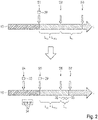
- Fig. 2 illustrates this by a comparison of the reduction of the "Remote Vehicle Latency” (L rv ) by using "early steering signal” or preparation signal 33 at the command center CC.
- the top time line illustrates over time t that at a step S1 the command center 12 may send a steering command 29 to the vehicle 11 without any preceding preparation signal.
- the vehicle 11 receives the steering command 29 in a step S2, the vehicle 11 has to perform all execution tasks 36 belonging to the intended driving manoeuver.
- the execution tasks 36 comprise both the preparation tasks 34 and the driving tasks 35.
- the driving manoeuver is finished or completed by executing all execution tasks 36 resulting in remove vehicle latency L rv .
- the command center 12 sends the preparation signal 33 such that vehicle 11 will perform or execute the preparation tasks 34 as preparatory execution tasks.
- the command center 12 sends the actual steering command 29 for changing the driving state for the driving manoeuver, the preparation tasks 34 belonging to this driving manoeuver have already been executed such that the vehicle only needs to perform the remaining driving tasks 35 of the set of execution tasks 36 belonging to the driving manoeuver.
- vehicle may react or respond to the steering command 29 by finishing the driving manoeuver in a step S7 with a shortened latency L rv .
- the workstation 20 comprises the ability to generate intention data 24 that indicate which preparation signal 33 is to be sent, i.e. which at least one preparation task is to be executed by the vehicle 11.
- Fig. 3 illustrates an exemplary workstation 20 like it may be provided in the command center 12.
- the steering data 23 presenting the sensor data 27, at least one display 40 may be provided in the workstation 20.
- the workstation 20 may comprise, for example, a steering wheel 41 and/or at least one pedal 42 for accelerating and/or braking the vehicle 11.
- the corresponding intention data 24 may be generated by an intention signaling element 43 that may comprise at least one button 44 that the operator 14 may press to indicate whether the operator 14 intends to drive forwards or backwards or left or right as a general maneuver class. Additionally or alternatively, an intention signaling element 43 may be provided where the operator 14 may indicate a sector 45 around the vehicle 11 (represented for example by a symbol 11'). Each sector 45 may indicate a class of driving manoeuvers that lead or drive the vehicle 11 into the respective sector 45 (e.g. front, forward left, forward right, backwards, backwards left, backwards right).
- an observation circuitry 46 may observe the operator 14 and may estimate or derive the intention data 24 depending on an observed behavior or a movement of the operator 14, for example when the operator 14 turns the head and observes a region to the left of the vehicle 11, the intention data 24 may indicate that the operator 14 intends to perform a driving manoeuver for turning the vehicle 11 to the left.
- the described elements of the workstation 20 constitute the user interface 21.
Landscapes
- Engineering & Computer Science (AREA)
- Radar, Positioning & Navigation (AREA)
- Remote Sensing (AREA)
- Aviation & Aerospace Engineering (AREA)
- Physics & Mathematics (AREA)
- General Physics & Mathematics (AREA)
- Automation & Control Theory (AREA)
- Control Of Driving Devices And Active Controlling Of Vehicle (AREA)
- Control Of Position, Course, Altitude, Or Attitude Of Moving Bodies (AREA)
Abstract
Description
- The invention is concerned with a method for a tele-operated driving of a vehicle. The vehicle is controlled from a command center, e.g. a remote stationary control center, via a communication network. The method comprises that the command center transmits a steering command to the vehicle over the communication network to change a driving state of the vehicle (e.g. either turn left or right and/or either accelerate or break) in order to execute a driving maneuver. The invention also provides a command center for performing the method and a system for the tele-operated driving of a vehicle.
- Tele-operated Driving (ToD) is a technology that is becoming a key enabler for automated driving, i.e. autonomous driving functions in vehicles. In addition to providing the support of a command center (CC) to solve deadlock situations, that is situation that the automated vehicle (AV) cannot solve by itself, tele-operated driving is becoming a legal requirement for automated driving in an increasing number of countries.
- However, high latencies on the remote vehicle side must be expected. They are mainly caused by the delays coming from the controller, actuators and internal communications in the vehicle. These latencies introduce operating delays, especially, when the vehicle is standing still and the command center triggers the start of a drive, e.g. when a traffic light switches from red to green.
- Document
US 2020 / 0019166 A1 describes such a method for tele-operated driving of a vehicle. The vehicle is also an autonomous vehicle that may perform driving manoeuvers in an automated manner by itself, but if a deadlock situation is detected, the vehicle requests assistance from a remote assistor in a command center. The assistor is only able to select certain autonomous driving manoeuvers, i.e. the assistor is not able to manually perform single driving manoeuvers of an own choice, like, e.g., turning the driving wheel. - Document
WO 2019 / 180700 A1 describes a system comprising a tele-operated vehicle, where a steering command for the vehicle may be generated by a remote artificial intelligence unit. A steering command may trigger a sequence of operations or tasks in the vehicle. This implies that when such a steering command is transmitted to the vehicle, the remote control center has to wait until the sequence of operations or tasks is executed, before the next steering command may be transmitted for adapting to the new driving situation resulting from the previous steering command. -
Document EP 3 295 268 B1 describes an autonomous vehicle operated with guide assistance. The guide assistance may be provided by a human operator who is located remotely from the vehicle and operates a user interface that displays predetermined operations for which the operator can make a selection and the selected operation can then be converted to instructions for the autonomous vehicle. Thus, after selecting an operation, the operator has to wait until the autonomous vehicle has finished all the instructions of the selected operation before the next operation may be selected. - Thus, in the prior art there is the problem that when a human operator triggers a steering command for changing the driving state of a tele-operated vehicle, for example for changing the driving speed and/or changing the driving direction, the set of instructions or tasks that need to be executed for changing the driving state may that numerous and slow that an unwanted or significant latency results from the moment the operator selects the steering command to the moment the new driving state is reached. One important example is the start of the tele-operated vehicle from a standstill, e.g. at a traffic light.
- It is an object of the present invention to reduce the amount of time a human operator has to wait from the moment that the operator initiates a steering command for changing a driving state of a tele-operated vehicle until the new driving state is reached.
- The object is accomplished by the subject matter of the independent claims. Advantageous developments with convenient and non-trivial further embodiments of the invention are specified in the following description, the dependent claims and the figures.
- One aspect of the invention is a method for a tele-operated driving of a vehicle, wherein the vehicle is controlled from a command center, e.g. a remote station, via a communication network. The method comprises that the command center transmits a steering command to the vehicle over the communication network to change a driving state of the vehicle in order to execute a driving maneuver. The change of the driving state means that the steering command changes a driving speed and/or steering angle, e.g. by driving left / right, accelerating, braking the vehicle.
- An operator in the control center should not experience a large latency from the moment the steering command is triggered to the successful execution of the steering command, i.e. the change of the driving state of the vehicle.
- The invention is based on the following insight. The driving maneuver generally comprises a whole sequence of execution tasks or instructions or operations. One or some of these execution tasks actually do not change the driving state, but rather prepare the vehicle for changing the driving state. For example, before a steering is turned left or right, the vehicle needs to verify that no other traffic participant is close to the vehicle or located along the new driving direction. This can be done by an electronic processing circuitry of the vehicle for observing the environment. In a normal tele-operated driving according to the prior art, after receiving a steering command for turning left or right this would result in the described latency period that is needed for verifying that the environment is clear before the steering is actually turned or changed. This would result in the described latency period.
- According to the invention, the execution tasks associated with a single steering command are split into two groups of tasks, namely the "preparation tasks" for initiating or preparing the driving maneuver and the actual "driving tasks" for actually or finally changing the driving state for the driving maneuver. Consequently, according to the inventive method, before the actual steering command is transmitted to the vehicle, the command center transmits a preceding separate "preparation signal" to the vehicle for triggering some or all of those of the execution tasks for which a current driving state of the vehicle remains unchanged (i.e. the preparation tasks that do not change the driving state) and afterwards, the following steering command comprises the at least one remaining final execution task (i.e. the driving tasks that change of steering angle, acceleration, braking) that causes the vehicle to actually change its driving state according to the driving maneuver.
- This provides the benefit that when the operator in the control center actually triggers the steering command, the vehicle is able to react in less time or with less latency by immediately changing the driving state, as some or any preparation task (belonging to the driving maneuver) has already been triggered and executed due to the preceding preparation signal. For example, if the driving manoeuver is to turn left or right, the steering command would be the change of the steering angle, but the described verification that the environment to the left or right is clear of any other traffic participant can already be triggered in advance by the preparation signal.
- The invention also comprises embodiments that provide features which afford additional technical advantages.
- One embodiment comprises that for generating the steering command the command center receives "steering data" from a user interface that is operated by a human operator. For example, the user interface may provide a steering wheel and/or a brake pedal and/or an acceleration pedal such that the human operator may operate the user interface as though the operator was situated in the vehicle itself. Operating these elements of the user interface generates the steering data. For generating the preparation signal the command center receives "intention data" from the user interface. By means of the intention data the operator may signal, which driving manoeuver is to be performed next, i.e. which change of driving state is intended next. A corresponding preparation signal may be chosen and sent out to the vehicle before the steering data are generated. Thus, the latency can be reduced by means of the preparation signal, the reaction of the vehicle to the operation of the user interface, i.e. the generation of the steering data, is then more prompt than without the use of the preparation signal.
- For generating the intention data, one embodiment comprises that the user interface comprises at least one "intention signaling element" that generates the intention data if operated by the operator. The intention signaling element comprises at least one selection button for selecting a respective driving maneuver and if the respective selection button is operated, intention data associated with this selection button are signaled. In other words, by pressing the corresponding button, intention data for a certain driving manoeuver, for example turning left or right or accelerating or braking, may be signaled or generated. When the operator later turns the driving wheel of the user interface and/or operates a pedal, the steering data for triggering the actual steering command follow.
- Additionally or alternatively to the at least one selection button an observation circuitry detects at least one predefined operator behavior (e.g. looking in the side mirror and/or back mirror) associated with the initiation of the driving maneuver. If such an operator behavior is detected, associated intention data for the driving maneuver are signaled. For example, an operator behavior may be the operator looking in the side mirror or back mirror and/or the turning of the head to one side. This may be interpreted as the intention to turn the vehicle left or right (depending on the direction that the operator is looking at). Likewise, a foot of the operator may be observed for detecting a change of the position of the foot, for example the placement of the foot on the accelerator pedal or the brake pedal. The observation circuitry may comprise a camera with an image processing circuitry and/or a proximity and/or pressure sensor for a pedal. The association of sensor data (e.g. image data) with a specific driving manoeuver may be performed on the basis of a machine learning algorithm that may be implemented on the basis of an artificial neural network.
- One embodiment comprises that the "intention data" directly indicate the one specific driving maneuver and the preparation signal triggers one or some or all of the execution tasks that do not change the driving state. In other words, for each driving manoeuver specific or individual intention data are provided.
- Alternatively, the indention data only indicate a class of driving maneuvers that have in common at least one common execution task that does not change the driving state. For example, the intention data may prepare the vehicle for heading forward or heading into a left direction or right direction, without specifying a specific driving manoeuver, for example the trajectory. For example, if the class of driving manoeuver is "deceleration", this may comprise several driving manoeuvers, for example braking, rolling out, opening the clutch which all decelerate the vehicle. The preparation signal then triggers the at least one common execution tasks in the vehicle and the vehicle may then wait for the more specific steering command for finalizing the driving maneuver.
- One embodiment comprises that the class of driving maneuvers is a selection out of several different pre-defined maneuver classes of driving maneuvers. These maneuver classes comprise at least one of the following: driving forwards, driving backwards, heading left, heading right, overtaking, starting the vehicle from standstill, braking the vehicle into standstill. In other words, each maneuver class defines the basic common execution tasks for driving in a general direction or aiming at a general goal and especially without defining the maneuver details, like, e.g., a trajectory.
- The respective specific execution task that is triggered by the preparation signal (i.e. the respective preparation task) can only be triggered as part of a preparation signal, i.e. it is an embedded task. One embodiment comprises that one or some or any execution task that is triggered by the preparation signal (i.e. the preparation tasks) is an embedded task that is not represented on the user interface by a dedicated operating element (e.g. a button).
- One embodiment comprises that after the preparation signal has been sent to the vehicle, the command center starts a timer for measuring a predefined waiting time and if the command center does not receive the corresponding steering data for the steering command within the waiting time, an undo signal is transmitted to the vehicle for undoing any execution task that was triggered by the preparation signal. The command center thus transmits the steering command only, if the corresponding user's steering data from the user interface are received within the waiting time. Otherwise, when the timer runs out and no steering data were received, an undo-signal is transmitted to the vehicle for undoing the any execution task (preparation task) that was triggered by the preparation signal. In other words, after the preparation signal has been sent to the vehicle and if no steering command follows, the vehicle is set back into the driving condition before the preparation signal, i.e. the vehicle is set back into the original driving state from before the preparation signal. This prepares the vehicle for the next preparation signal.
- The method can be used for resolving a deadlock situation of the vehicle, if the vehicle is an autonomous vehicle or if a driver of the vehicle is unable to cope and asks for help at the command center. One embodiment comprises that the vehicle is controlled in the described way after the vehicle has been driving autonomously or by a driver and has detected a pre-defined deadlock situation causing the vehicle to stop moving and the command center has received a request of the vehicle to assist in resolving the deadlock situation and has started a tele-operated driving session. This provided the benefit that a human operator at the command center is available when the autonomous driving function of the vehicle or the driver is unable to resolve a driving situation itself (i.e. a deadlock situation).
- One embodiment comprises that said deadlock situation describes a detection of an obstacle (e.g. a road-blocking vehicle with a breakdown) and/or a road situation (e.g. roadworks) in the surrounding or in a current trajectory of the vehicle, for which an autonomous driving maneuver is not available to the autonomous driving function of the vehicle. Such deadlock situations are possible to define precisely and the can also be reliably detected by the autonomous driving function.
- One embodiment comprises that the driving maneuver is a start / acceleration of the vehicle from standstill and the preparation signal triggers one or some or all of the following preparatory execution tasks:
- disengage parking brake,
- setup break pressure,
- change to gear one or reverse gear,
- activate day time running lights or lights,
- turn the steering in a defined direction,
- adjust at least one sensor (e.g. a camera) of the vehicle in the defined direction. This is based on the rationale that a start of the vehicle can be a maneuver with many preparatory execution tasks (preparation tasks) that cause an unwanted latency, if they are linked directly to the steering command without the preparation signal.
- The invention also comprises a command center for a tele-operated driving of a vehicle, wherein the command center comprises an electronic processing circuitry that is designed to perform a method according to the invention. The command center can be a building where a human operator may sit at a workstation that provides the described user interface for remotely controlling the vehicle. The electronic processing circuitry may comprise at least one microprocessor that is linked to a data storage. The data storage may store programming instructions that cause the at least one microprocessor to perform the described method when executed by the at least one microprocessor.
- By combining the command center and at least one vehicle of the described kind, a system is obtained that is also part of the invention. The invention also comprises this system with a command center according to the invention and a vehicle that is designed to receive at least one preparation signal and execute the execution tasks associated with the respective preparation signal (i.e. the preparation tasks) and that is further designed to receive at least one steering command and change a driving state, in particular turn a steering and/or accelerate and/or decelerate, according to the steering command.
- The invention also comprises the combinations of the features of the different embodiments.
- In the following exemplary implementations of the invention are described. The figures show:
- Fig. 1
- a schematic illustration of an embodiment of the inventive system;
- Fig. 2
- a diagram for illustrating the effect of a preparation signal; and
- Fig. 3
- a schematic illustration of a workstation at a command center of the system of
Fig. 1 . - The embodiments explained in the following are a preferred embodiments of the invention. However, in the embodiments, the described components of the embodiment each represent individual features of the invention which are to be considered independently of each other and which each develop the invention also independently of each other and thereby are also to be regarded as a component of the invention in individual manner or in another than the shown combination. Furthermore, the described embodiment can also be supplemented by further features of the invention already described.
- In the figures identical reference signs indicate elements that provide the same function.
-
Fig. 1 shows asystem 10 with avehicle 11 and a command center 12 (CC) for remotely controlling or operating thevehicle 11 for performing driving maneuvers. From the perspective of thecommand center 12, thevehicle 11 therefore is a remote vehicle RV. Thevehicle 11 may comprise anautonomous driving function 13 for driving thevehicle 11 autonomously without the support of a human driver (AV - autonomous vehicle). However, when theautonomous driving function 13 detects a deadlock situation for which a driving manoeuver is not available in theautonomous driving function 13, the vehicle may request the support of anoperator 14 in thecommand center 12 by means of a request message R. For a communication between the vehicle 11 (e.g. an electronic processing circuitry or central computer of the vehicle 11) and a processing circuitry CPU of thecommand center 12, acommunication link 15 may be established. Communication in 15 may be based on awireless connection 16, for example based on acellular network 17 and/or Wi-Fi, and/or an Internet connection over the Internet at 18.Vehicle 11 may comprise acorresponding communication unit 19 for thewireless connection 16. - The
operator 14 may handle aworkstation 20 that provides auser interface 21 for receiving input data 22 from theoperator 14. Such input data 22 may comprisesteering data 23 that describe a driving manoeuver intended by theoperator 14 andintention data 24 that indicate which driving manoeuver theoperator 14 is planning the next. - For this tele-operated driving of the
vehicle 11, thecommand center 12 may perform a method, wherein based on the request message R, theoperator 14 at thecommand center 12 monitors surrounding 25 of thevehicle 11 and/or assesses the conflicting situation on the basis of the at least one sensor 26 of thevehicle 11. The at least one sensor 26 may provide sensor data 27 of thesurroundings 25 and the sensor data 27 may be transmitted to thecontrol center 12 where they may be presented to theoperator 14 by theuser interface 21. In thecontrol center 12 the sensor data 27 may be received by an uplink controller UL for receiving, for example, video data. The uplink controller UL may comprise a video codec for presenting your information to theoperator 14 that may be provided by one or more than one sensor 26 of thevehicle 11 that may be designed as a camera. - Depending on the observed conflicting situation, the
operator 14 at thecommand center 12 may decide a respective control strategy of thevehicle 11. The respective control strategy describes a direct control (e.g. a closed loop control) and/or an indirect control (e.g. supervisory control by monitoring and giving high-level commands to the vehicle) of thevehicle 11 by theoperator 14 at thecommand center 12. Thecontrol center 12 may comprise adownlink control 28 for a downlink connection to thevehicle 11. Depending on the input data 22, thedownlink control 28 may generate at least onesteering command 29 for setting a steering angle and/or an acceleration and/or braking force forvehicle 11.Vehicle 11 may comprise adownlink control 30 that may receive thesteering command 29 and may provide for the downlink DL the command to acontroller 31 that may control at least oneactuator 32 for drivingvehicle 11. - One use case of tele-operated driving ToD is the resolution of said deadlock situation by the command center CC. Two types of controls in the downlink DL may be distinguished: direct and indirect control.
-
Fig. 1 also depicts in addition to the ToD architecture of thesystem 10, its latencies in the downlink DL. In particular, the total latency in the DL is obtained by summing up three latencies: latencies at the remote vehicle Lrv (including latencies of controller, sensors and actuators in the vehicle), latencies in the communication network Lqos and latencies at the command center CC, i.e. Lcc (including reaction time of thehuman operator 14 or driver). Besides the latencies Lcc at the command center CC, theremote vehicle 11 contributes significantly to the total latency. - In order to reduce the operational delay, the latency Lrv in the
autonomous vehicle 11 is reduced. This is done by having the command center CC sending a preceding "early steering signal" orpreparation signal 33 to thevehicle 11 before sending the actual steering command for a specific driving maneuvers. - In particular, a
preparation signal 33 makes thevehicle 11 aware of or prepare for the intended maneuver of theoperator 14 at command center CC. Receiving thispreparation signal 33, thevehicle 11 may trigger and executepreparation tasks 34 such as: - Disengage parking brake and/or
- Reduce brake pressure and/or
- Change gears
- After the
preparation tasks 34 are completed, thevehicle 11 is prepared to immediately perform remainingdriving tasks 35 that actually cause thevehicle 11 to change its driving state. The drivingtasks 35 may be triggered by thesteering command 29. - Correspondingly, the following steps may be performed by the
system 10 for performing a driving manoeuver with theautonomous vehicle 11. - Once the ToD session is started (meaning that the
vehicle 11 already detected the deadlock, stopped in a safe state and called the CC by means of the request message R), the steps can be: - 1. CC decides for a solution e.g. CC will steer AV by direct control in drive direction. This can be done by the
operator 14. - 2. CC sends a "early steering signal", i.e. the
preparation signal 33, which includes the intention of the solution of the previous step and triggers the at least onepreparation task 34 e.g.:- Disengage parking brake
- Setup brake pressure for normal brake
- Change to gear one
- Chose daytime running lights
- 3. The
vehicle 11 prepares for at least oneupcoming steering command 29 from CC. - 4. CC sends steering signals or steering commands 29 to the
vehicle 11. -
Step number 2 will be the main impacting step in the delay reduction. -
Fig. 2 illustrates this by a comparison of the reduction of the "Remote Vehicle Latency" (Lrv) by using "early steering signal" orpreparation signal 33 at the command center CC. The top time line illustrates over time t that at a step S1 thecommand center 12 may send asteering command 29 to thevehicle 11 without any preceding preparation signal. Once thevehicle 11 receives thesteering command 29 in a step S2, thevehicle 11 has to perform allexecution tasks 36 belonging to the intended driving manoeuver. Theexecution tasks 36 comprise both thepreparation tasks 34 and the drivingtasks 35. At a step S3 the driving manoeuver is finished or completed by executing allexecution tasks 36 resulting in remove vehicle latency Lrv. - By introducing the
preparation signal 33, the bottom timeline results. In a step S4 thecommand center 12 sends thepreparation signal 33 such thatvehicle 11 will perform or execute thepreparation tasks 34 as preparatory execution tasks. When at a step S5 thecommand center 12 sends theactual steering command 29 for changing the driving state for the driving manoeuver, thepreparation tasks 34 belonging to this driving manoeuver have already been executed such that the vehicle only needs to perform the remainingdriving tasks 35 of the set ofexecution tasks 36 belonging to the driving manoeuver. Thus, after receiving thesteering command 29 in a step S6, vehicle may react or respond to thesteering command 29 by finishing the driving manoeuver in a step S7 with a shortened latency Lrv. - In the step S4, in the command center it must be known which
preparation signal 33 is to be sent or in other words what is the intention of theoperator 14. To this end, theworkstation 20 comprises the ability to generateintention data 24 that indicate whichpreparation signal 33 is to be sent, i.e. which at least one preparation task is to be executed by thevehicle 11. -
Fig. 3 illustrates anexemplary workstation 20 like it may be provided in thecommand center 12. For generating thesteering data 23, presenting the sensor data 27, at least onedisplay 40 may be provided in theworkstation 20. For generating thesteering data 23, theworkstation 20 may comprise, for example, asteering wheel 41 and/or at least onepedal 42 for accelerating and/or braking thevehicle 11. - For generating the
preparation signal 33, thecorresponding intention data 24 may be generated by anintention signaling element 43 that may comprise at least onebutton 44 that theoperator 14 may press to indicate whether theoperator 14 intends to drive forwards or backwards or left or right as a general maneuver class. Additionally or alternatively, anintention signaling element 43 may be provided where theoperator 14 may indicate asector 45 around the vehicle 11 (represented for example by a symbol 11'). Eachsector 45 may indicate a class of driving manoeuvers that lead or drive thevehicle 11 into the respective sector 45 (e.g. front, forward left, forward right, backwards, backwards left, backwards right). - Additionally or alternatively an
observation circuitry 46 may observe theoperator 14 and may estimate or derive theintention data 24 depending on an observed behavior or a movement of theoperator 14, for example when theoperator 14 turns the head and observes a region to the left of thevehicle 11, theintention data 24 may indicate that theoperator 14 intends to perform a driving manoeuver for turning thevehicle 11 to the left. - The described elements of the
workstation 20 constitute theuser interface 21. - Overall, the example shows how a method for setting-up a quick start of a remote vehicle is provided by the invention.
-
- 10
- system
- 11
- vehicle
- 12
- center
- 13
- autonomous driving function
- 14
- operator
- 15
- link
- 16
- connection
- 17
- network
- 19
- communication unit
- 20
- workstation
- 21
- user interface
- 22
- input data
- 23
- intention data
- 24
- steering data
- 25
- surroundings
- 26
- sensor
- 27
- sensor data
- 28
- downlink control
- 29
- steering command
- 30
- uplink control
- 31
- controller
- 32
- actuator
- 33
- preparation signal
- 34
- execution task
- 40
- display
- 41
- wheel
- 42
- pedal
- 43
- operating element
- 44
- button
- 45
- sector
- 46
- observation circuitry
Claims (12)
- Method for a tele-operated driving of a vehicle (11), wherein the vehicle (11) is controlled from a command center (12) via a communication network (17) and wherein the method comprises that the command center (12) transmits a steering command (29) to the vehicle (11) over the communication network (17) to change a driving state of the vehicle (11) in order to execute a driving maneuver, characterized in that
the driving maneuver comprises a sequence of execution tasks (36) and before the steering command (29) is transmitted to the vehicle (11), the command center (12) transmits a separate preparation signal (33) to the vehicle (11) for triggering some or all of those of the execution tasks (36) for which a current driving state of the vehicle (11) remains unchanged and the following steering command (29) comprises the at least one remaining final execution task (36) that causes the vehicle (11) to change its driving state according to the driving maneuver. - Method according to claim 1, wherein for generating the steering command (29) the command center (12) receives steering data (23) from a user interface (21) that is operated by a human operator (14), and for generating the preparation signal (33) the command center (12) receives intention data (24) from the user interface (21).
- Method according to claim 2, wherein the user interface (21) comprises an intention signaling element (43) that generates the intention data (24), wherein the intention signaling element (43) comprises
at least one selection button (44) for selecting a respective driving maneuver and if the respective selection button (44) is operated by the operator (14), intention data (24) associated with this selection button (44) are signaled, and/or
an observation circuitry (46) that detects at least one predefined operator behavior associated with the initiation of the driving maneuver and if the operator behavior is detected, associated intention data (24) for the associated driving maneuver is signaled. - Method according to claim 2 or 3, wherein- the intention data (24) directly indicate the one specific driving maneuver and the preparation signal (33) triggers one or some or all of those execution tasks (36) for that specific driving maneuver that do not change the driving state or- wherein the intention data (24) indicate a class of driving maneuvers that have in common at least one common execution task (36) that does not change the driving state in any of these driving maneuvers and the preparation signal (33) triggers the at least one common execution task (36).
- Method according to claim 4, wherein the class of driving maneuvers is selected out of several different pre-defined maneuver classes of driving maneuvers, wherein the maneuver classes comprise at least one of the following: driving forwards, driving backwards, heading left, heading right, overtaking, starting the vehicle (11) from standstill, braking the vehicle (11) into standstill.
- Method according to any of the claims 2 to 5, wherein one or some or any execution task (36) that is triggered by the preparation signal (33) is an embedded task that is not represented on the user interface (21) for separate execution.
- Method according to any of the claims 2 to 6, wherein after the preparation signal (33) has been sent to the vehicle (11), the command center (12) starts a timer for measuring a predefined waiting time and if the command center (12) does not receive the corresponding steering data (23) for the steering command (29) within the waiting time, an undo signal is transmitted to the vehicle (11) for undoing any execution task (36) that was triggered by the preparation signal (33).
- Method according to any of the preceding claims, wherein the vehicle (11) is controlled after the vehicle (11) has been driving autonomously and has detected a pre-defined deadlock situation causing the vehicle (11) to stop moving and after the command center (12) has received a request of the vehicle (11) to assist in resolving the deadlock situation and has started a tele-operated driving session.
- Method according to claim 8, wherein the deadlock situation describes a detection of an obstacle and/or a road situation in a surrounding (25) or along a current trajectory of the vehicle (11), for which an autonomous drive maneuver is not available to the vehicle (11).
- Method according to any of the preceding claims, wherein the driving maneuver is a start of the vehicle (11) from standstill and the preparation signal (33) triggers one or some or all of the following execution tasks:- disengage parking brake,- setup break pressure,- change to gear one or reverse gear,- activate day time running lights or lights,- turn the steering in a defined direction,- adjust at least one sensor (26) of the vehicle (11) in the defined direction.
- Command center for a tele-operated driving of a vehicle (11), wherein the command center (12) comprises an electronic processing circuitry that is designed to perform a method according to one of the preceding claims.
- System with a command center (12) according to claim 11 and a vehicle (11) that is designed to receive at least one preparation signal (33) and execute execution tasks (36) associated with the respective preparation signal (33) and that is designed to receive at least one steering command (29) and change a driving state, in particular turn a steering and/or accelerate and/or decelerate, according to the steering command (29).
Priority Applications (1)
| Application Number | Priority Date | Filing Date | Title |
|---|---|---|---|
| EP20209655.8A EP4002045B1 (en) | 2020-11-24 | 2020-11-24 | Method and command center for a tele-operated driving of a vehicle and corresponding system with a command center and a vehicle |
Applications Claiming Priority (1)
| Application Number | Priority Date | Filing Date | Title |
|---|---|---|---|
| EP20209655.8A EP4002045B1 (en) | 2020-11-24 | 2020-11-24 | Method and command center for a tele-operated driving of a vehicle and corresponding system with a command center and a vehicle |
Publications (2)
| Publication Number | Publication Date |
|---|---|
| EP4002045A1 true EP4002045A1 (en) | 2022-05-25 |
| EP4002045B1 EP4002045B1 (en) | 2025-01-08 |
Family
ID=73597853
Family Applications (1)
| Application Number | Title | Priority Date | Filing Date |
|---|---|---|---|
| EP20209655.8A Active EP4002045B1 (en) | 2020-11-24 | 2020-11-24 | Method and command center for a tele-operated driving of a vehicle and corresponding system with a command center and a vehicle |
Country Status (1)
| Country | Link |
|---|---|
| EP (1) | EP4002045B1 (en) |
Citations (5)
| Publication number | Priority date | Publication date | Assignee | Title |
|---|---|---|---|---|
| WO2019180700A1 (en) | 2018-03-18 | 2019-09-26 | Liveu Ltd. | Device, system, and method of autonomous driving and tele-operated vehicles |
| US20200019166A1 (en) | 2014-03-03 | 2020-01-16 | Waymo Llc | Remote assistance for an autonomous vehicle in low confidence situations |
| US20200041995A1 (en) * | 2018-10-10 | 2020-02-06 | Waymo Llc | Method for realtime remote-operation of self-driving cars by forward scene prediction. |
| EP3295268B1 (en) | 2015-05-13 | 2020-05-06 | Uber Technologies, Inc. | Autonomous vehicle operated with guide assistance |
| WO2020200534A1 (en) * | 2019-04-05 | 2020-10-08 | Robert Bosch Gmbh | Method and apparatus for controlling a vehicle by means of a remote operator |
-
2020
- 2020-11-24 EP EP20209655.8A patent/EP4002045B1/en active Active
Patent Citations (5)
| Publication number | Priority date | Publication date | Assignee | Title |
|---|---|---|---|---|
| US20200019166A1 (en) | 2014-03-03 | 2020-01-16 | Waymo Llc | Remote assistance for an autonomous vehicle in low confidence situations |
| EP3295268B1 (en) | 2015-05-13 | 2020-05-06 | Uber Technologies, Inc. | Autonomous vehicle operated with guide assistance |
| WO2019180700A1 (en) | 2018-03-18 | 2019-09-26 | Liveu Ltd. | Device, system, and method of autonomous driving and tele-operated vehicles |
| US20200041995A1 (en) * | 2018-10-10 | 2020-02-06 | Waymo Llc | Method for realtime remote-operation of self-driving cars by forward scene prediction. |
| WO2020200534A1 (en) * | 2019-04-05 | 2020-10-08 | Robert Bosch Gmbh | Method and apparatus for controlling a vehicle by means of a remote operator |
Also Published As
| Publication number | Publication date |
|---|---|
| EP4002045B1 (en) | 2025-01-08 |
Similar Documents
| Publication | Publication Date | Title |
|---|---|---|
| US20150006013A1 (en) | Device for the automated driving of a motor vehicle, motor vehicle having such a device and method for operating a motor vehicle | |
| CN111731287A (en) | Change operation aids | |
| EP4344971B1 (en) | Vehicle guidance system and method for operating a driving function as a function of driver data | |
| US7246675B2 (en) | Adjustment of the speed of a motor vehicle with an automatic gearbox | |
| JP2007196809A (en) | Automatic operation control device | |
| WO2022078846A1 (en) | Vehicle control system and method for operating a driving function upon actuation of the accelerator pedal | |
| DE112016002612T5 (en) | Vehicle control device, vehicle control method and vehicle control program | |
| CN109963736B (en) | Shift selector device | |
| JP6828580B2 (en) | Vehicle control device | |
| CN111661035A (en) | Automatic parking control method and device and vehicle | |
| JP4895003B2 (en) | Automatic operation control device | |
| US20230406313A1 (en) | Vehicle Guidance System and Method for Automated Starting of a Vehicle | |
| JP2018527237A (en) | Vehicle speed control method and vehicle speed control system | |
| US11007879B2 (en) | Method for operating a motor vehicle and motor vehicle | |
| WO2022078845A1 (en) | Vehicle control system and method for operating a driving function in different driving modes | |
| CN112334379B (en) | Parking assistant for automatic parking from longitudinal parking spaces using the reversing step as the final parking step | |
| JP2007196808A (en) | Automatic operation control device | |
| EP4002045B1 (en) | Method and command center for a tele-operated driving of a vehicle and corresponding system with a command center and a vehicle | |
| EP4316939B1 (en) | Vehicle guidance system and method for operating a driving function in different modes | |
| JP7678407B2 (en) | Remote Parking Device | |
| EP4083475B1 (en) | Vehicle park-lock control method and park-lock control device | |
| WO2022078852A1 (en) | Vehicle guidance system and method for operating a driving function following a driving-off process | |
| JP7615980B2 (en) | Remote control device and remote control system | |
| CN118560484A (en) | Overtaking control method and system | |
| US20250100573A1 (en) | Vehicle control device, vehicle control method, and storage medium |
Legal Events
| Date | Code | Title | Description |
|---|---|---|---|
| PUAI | Public reference made under article 153(3) epc to a published international application that has entered the european phase |
Free format text: ORIGINAL CODE: 0009012 |
|
| STAA | Information on the status of an ep patent application or granted ep patent |
Free format text: STATUS: THE APPLICATION HAS BEEN PUBLISHED |
|
| AK | Designated contracting states |
Kind code of ref document: A1 Designated state(s): AL AT BE BG CH CY CZ DE DK EE ES FI FR GB GR HR HU IE IS IT LI LT LU LV MC MK MT NL NO PL PT RO RS SE SI SK SM TR |
|
| STAA | Information on the status of an ep patent application or granted ep patent |
Free format text: STATUS: REQUEST FOR EXAMINATION WAS MADE |
|
| 17P | Request for examination filed |
Effective date: 20221125 |
|
| RBV | Designated contracting states (corrected) |
Designated state(s): AL AT BE BG CH CY CZ DE DK EE ES FI FR GB GR HR HU IE IS IT LI LT LU LV MC MK MT NL NO PL PT RO RS SE SI SK SM TR |
|
| STAA | Information on the status of an ep patent application or granted ep patent |
Free format text: STATUS: EXAMINATION IS IN PROGRESS |
|
| 17Q | First examination report despatched |
Effective date: 20231108 |
|
| GRAP | Despatch of communication of intention to grant a patent |
Free format text: ORIGINAL CODE: EPIDOSNIGR1 |
|
| STAA | Information on the status of an ep patent application or granted ep patent |
Free format text: STATUS: GRANT OF PATENT IS INTENDED |
|
| INTG | Intention to grant announced |
Effective date: 20240912 |
|
| P01 | Opt-out of the competence of the unified patent court (upc) registered |
Free format text: CASE NUMBER: APP_51562/2024 Effective date: 20240912 |
|
| GRAS | Grant fee paid |
Free format text: ORIGINAL CODE: EPIDOSNIGR3 |
|
| GRAA | (expected) grant |
Free format text: ORIGINAL CODE: 0009210 |
|
| STAA | Information on the status of an ep patent application or granted ep patent |
Free format text: STATUS: THE PATENT HAS BEEN GRANTED |
|
| AK | Designated contracting states |
Kind code of ref document: B1 Designated state(s): AL AT BE BG CH CY CZ DE DK EE ES FI FR GB GR HR HU IE IS IT LI LT LU LV MC MK MT NL NO PL PT RO RS SE SI SK SM TR |
|
| REG | Reference to a national code |
Ref country code: GB Ref legal event code: FG4D |
|
| REG | Reference to a national code |
Ref country code: CH Ref legal event code: EP |
|
| REG | Reference to a national code |
Ref country code: DE Ref legal event code: R096 Ref document number: 602020044442 Country of ref document: DE |
|
| REG | Reference to a national code |
Ref country code: IE Ref legal event code: FG4D |
|
| REG | Reference to a national code |
Ref country code: LT Ref legal event code: MG9D |
|
| REG | Reference to a national code |
Ref country code: NL Ref legal event code: MP Effective date: 20250108 |
|
| REG | Reference to a national code |
Ref country code: AT Ref legal event code: MK05 Ref document number: 1758750 Country of ref document: AT Kind code of ref document: T Effective date: 20250108 |
|
| PG25 | Lapsed in a contracting state [announced via postgrant information from national office to epo] |
Ref country code: NL Free format text: LAPSE BECAUSE OF FAILURE TO SUBMIT A TRANSLATION OF THE DESCRIPTION OR TO PAY THE FEE WITHIN THE PRESCRIBED TIME-LIMIT Effective date: 20250108 |
|
| PG25 | Lapsed in a contracting state [announced via postgrant information from national office to epo] |
Ref country code: RS Free format text: LAPSE BECAUSE OF FAILURE TO SUBMIT A TRANSLATION OF THE DESCRIPTION OR TO PAY THE FEE WITHIN THE PRESCRIBED TIME-LIMIT Effective date: 20250408 |
|
| PG25 | Lapsed in a contracting state [announced via postgrant information from national office to epo] |
Ref country code: FI Free format text: LAPSE BECAUSE OF FAILURE TO SUBMIT A TRANSLATION OF THE DESCRIPTION OR TO PAY THE FEE WITHIN THE PRESCRIBED TIME-LIMIT Effective date: 20250108 |
|
| PG25 | Lapsed in a contracting state [announced via postgrant information from national office to epo] |
Ref country code: PL Free format text: LAPSE BECAUSE OF FAILURE TO SUBMIT A TRANSLATION OF THE DESCRIPTION OR TO PAY THE FEE WITHIN THE PRESCRIBED TIME-LIMIT Effective date: 20250108 |
|
| PG25 | Lapsed in a contracting state [announced via postgrant information from national office to epo] |
Ref country code: ES Free format text: LAPSE BECAUSE OF FAILURE TO SUBMIT A TRANSLATION OF THE DESCRIPTION OR TO PAY THE FEE WITHIN THE PRESCRIBED TIME-LIMIT Effective date: 20250108 |
|
| PG25 | Lapsed in a contracting state [announced via postgrant information from national office to epo] |
Ref country code: NO Free format text: LAPSE BECAUSE OF FAILURE TO SUBMIT A TRANSLATION OF THE DESCRIPTION OR TO PAY THE FEE WITHIN THE PRESCRIBED TIME-LIMIT Effective date: 20250408 Ref country code: IS Free format text: LAPSE BECAUSE OF FAILURE TO SUBMIT A TRANSLATION OF THE DESCRIPTION OR TO PAY THE FEE WITHIN THE PRESCRIBED TIME-LIMIT Effective date: 20250508 |
|
| PG25 | Lapsed in a contracting state [announced via postgrant information from national office to epo] |
Ref country code: HR Free format text: LAPSE BECAUSE OF FAILURE TO SUBMIT A TRANSLATION OF THE DESCRIPTION OR TO PAY THE FEE WITHIN THE PRESCRIBED TIME-LIMIT Effective date: 20250108 |
|
| PG25 | Lapsed in a contracting state [announced via postgrant information from national office to epo] |
Ref country code: PT Free format text: LAPSE BECAUSE OF FAILURE TO SUBMIT A TRANSLATION OF THE DESCRIPTION OR TO PAY THE FEE WITHIN THE PRESCRIBED TIME-LIMIT Effective date: 20250508 Ref country code: LV Free format text: LAPSE BECAUSE OF FAILURE TO SUBMIT A TRANSLATION OF THE DESCRIPTION OR TO PAY THE FEE WITHIN THE PRESCRIBED TIME-LIMIT Effective date: 20250108 |
|
| PG25 | Lapsed in a contracting state [announced via postgrant information from national office to epo] |
Ref country code: BG Free format text: LAPSE BECAUSE OF FAILURE TO SUBMIT A TRANSLATION OF THE DESCRIPTION OR TO PAY THE FEE WITHIN THE PRESCRIBED TIME-LIMIT Effective date: 20250108 Ref country code: GR Free format text: LAPSE BECAUSE OF FAILURE TO SUBMIT A TRANSLATION OF THE DESCRIPTION OR TO PAY THE FEE WITHIN THE PRESCRIBED TIME-LIMIT Effective date: 20250409 |
|
| PG25 | Lapsed in a contracting state [announced via postgrant information from national office to epo] |
Ref country code: AT Free format text: LAPSE BECAUSE OF FAILURE TO SUBMIT A TRANSLATION OF THE DESCRIPTION OR TO PAY THE FEE WITHIN THE PRESCRIBED TIME-LIMIT Effective date: 20250108 |
|
| PG25 | Lapsed in a contracting state [announced via postgrant information from national office to epo] |
Ref country code: SE Free format text: LAPSE BECAUSE OF FAILURE TO SUBMIT A TRANSLATION OF THE DESCRIPTION OR TO PAY THE FEE WITHIN THE PRESCRIBED TIME-LIMIT Effective date: 20250108 |
|
| PG25 | Lapsed in a contracting state [announced via postgrant information from national office to epo] |
Ref country code: SM Free format text: LAPSE BECAUSE OF FAILURE TO SUBMIT A TRANSLATION OF THE DESCRIPTION OR TO PAY THE FEE WITHIN THE PRESCRIBED TIME-LIMIT Effective date: 20250108 |
|
| REG | Reference to a national code |
Ref country code: DE Ref legal event code: R097 Ref document number: 602020044442 Country of ref document: DE |
|
| PG25 | Lapsed in a contracting state [announced via postgrant information from national office to epo] |
Ref country code: DK Free format text: LAPSE BECAUSE OF FAILURE TO SUBMIT A TRANSLATION OF THE DESCRIPTION OR TO PAY THE FEE WITHIN THE PRESCRIBED TIME-LIMIT Effective date: 20250108 |
|
| PG25 | Lapsed in a contracting state [announced via postgrant information from national office to epo] |
Ref country code: EE Free format text: LAPSE BECAUSE OF FAILURE TO SUBMIT A TRANSLATION OF THE DESCRIPTION OR TO PAY THE FEE WITHIN THE PRESCRIBED TIME-LIMIT Effective date: 20250108 Ref country code: CZ Free format text: LAPSE BECAUSE OF FAILURE TO SUBMIT A TRANSLATION OF THE DESCRIPTION OR TO PAY THE FEE WITHIN THE PRESCRIBED TIME-LIMIT Effective date: 20250108 |
|
| PG25 | Lapsed in a contracting state [announced via postgrant information from national office to epo] |
Ref country code: RO Free format text: LAPSE BECAUSE OF FAILURE TO SUBMIT A TRANSLATION OF THE DESCRIPTION OR TO PAY THE FEE WITHIN THE PRESCRIBED TIME-LIMIT Effective date: 20250108 |
|
| PG25 | Lapsed in a contracting state [announced via postgrant information from national office to epo] |
Ref country code: SK Free format text: LAPSE BECAUSE OF FAILURE TO SUBMIT A TRANSLATION OF THE DESCRIPTION OR TO PAY THE FEE WITHIN THE PRESCRIBED TIME-LIMIT Effective date: 20250108 |
|
| PLBE | No opposition filed within time limit |
Free format text: ORIGINAL CODE: 0009261 |
|
| STAA | Information on the status of an ep patent application or granted ep patent |
Free format text: STATUS: NO OPPOSITION FILED WITHIN TIME LIMIT |
|
| 26N | No opposition filed |
Effective date: 20251009 |
|
| PGFP | Annual fee paid to national office [announced via postgrant information from national office to epo] |
Ref country code: DE Payment date: 20251130 Year of fee payment: 6 |
|
| PGFP | Annual fee paid to national office [announced via postgrant information from national office to epo] |
Ref country code: GB Payment date: 20251125 Year of fee payment: 6 |
|
| PGFP | Annual fee paid to national office [announced via postgrant information from national office to epo] |
Ref country code: FR Payment date: 20251124 Year of fee payment: 6 |
|
| PG25 | Lapsed in a contracting state [announced via postgrant information from national office to epo] |
Ref country code: IT Free format text: LAPSE BECAUSE OF FAILURE TO SUBMIT A TRANSLATION OF THE DESCRIPTION OR TO PAY THE FEE WITHIN THE PRESCRIBED TIME-LIMIT Effective date: 20250108 |