EP4001895A1 - Clean gas curtain to prevent particle buildup during concentration measurement - Google Patents
Clean gas curtain to prevent particle buildup during concentration measurement Download PDFInfo
- Publication number
- EP4001895A1 EP4001895A1 EP21203295.7A EP21203295A EP4001895A1 EP 4001895 A1 EP4001895 A1 EP 4001895A1 EP 21203295 A EP21203295 A EP 21203295A EP 4001895 A1 EP4001895 A1 EP 4001895A1
- Authority
- EP
- European Patent Office
- Prior art keywords
- clean gas
- window
- housing
- particle
- gas inlets
- Prior art date
- Legal status (The legal status is an assumption and is not a legal conclusion. Google has not performed a legal analysis and makes no representation as to the accuracy of the status listed.)
- Granted
Links
Images



Classifications
-
- G—PHYSICS
- G01—MEASURING; TESTING
- G01N—INVESTIGATING OR ANALYSING MATERIALS BY DETERMINING THEIR CHEMICAL OR PHYSICAL PROPERTIES
- G01N21/00—Investigating or analysing materials by the use of optical means, i.e. using sub-millimetre waves, infrared, visible or ultraviolet light
- G01N21/01—Arrangements or apparatus for facilitating the optical investigation
- G01N21/15—Preventing contamination of the components of the optical system or obstruction of the light path
-
- G—PHYSICS
- G01—MEASURING; TESTING
- G01N—INVESTIGATING OR ANALYSING MATERIALS BY DETERMINING THEIR CHEMICAL OR PHYSICAL PROPERTIES
- G01N15/00—Investigating characteristics of particles; Investigating permeability, pore-volume or surface-area of porous materials
- G01N15/06—Investigating concentration of particle suspensions
-
- G—PHYSICS
- G01—MEASURING; TESTING
- G01N—INVESTIGATING OR ANALYSING MATERIALS BY DETERMINING THEIR CHEMICAL OR PHYSICAL PROPERTIES
- G01N15/00—Investigating characteristics of particles; Investigating permeability, pore-volume or surface-area of porous materials
- G01N15/06—Investigating concentration of particle suspensions
- G01N15/075—Investigating concentration of particle suspensions by optical means
-
- G—PHYSICS
- G01—MEASURING; TESTING
- G01N—INVESTIGATING OR ANALYSING MATERIALS BY DETERMINING THEIR CHEMICAL OR PHYSICAL PROPERTIES
- G01N15/00—Investigating characteristics of particles; Investigating permeability, pore-volume or surface-area of porous materials
- G01N2015/0042—Investigating dispersion of solids
- G01N2015/0046—Investigating dispersion of solids in gas, e.g. smoke
-
- G—PHYSICS
- G01—MEASURING; TESTING
- G01N—INVESTIGATING OR ANALYSING MATERIALS BY DETERMINING THEIR CHEMICAL OR PHYSICAL PROPERTIES
- G01N21/00—Investigating or analysing materials by the use of optical means, i.e. using sub-millimetre waves, infrared, visible or ultraviolet light
- G01N21/01—Arrangements or apparatus for facilitating the optical investigation
- G01N21/15—Preventing contamination of the components of the optical system or obstruction of the light path
- G01N2021/151—Gas blown
-
- G—PHYSICS
- G01—MEASURING; TESTING
- G01N—INVESTIGATING OR ANALYSING MATERIALS BY DETERMINING THEIR CHEMICAL OR PHYSICAL PROPERTIES
- G01N21/00—Investigating or analysing materials by the use of optical means, i.e. using sub-millimetre waves, infrared, visible or ultraviolet light
- G01N21/17—Systems in which incident light is modified in accordance with the properties of the material investigated
- G01N21/47—Scattering, i.e. diffuse reflection
- G01N21/4738—Diffuse reflection, e.g. also for testing fluids, fibrous materials
- G01N21/474—Details of optical heads therefor, e.g. using optical fibres
- G01N2021/4742—Details of optical heads therefor, e.g. using optical fibres comprising optical fibres
Definitions
- Exemplary embodiments pertain to the art of fire suppression and, in particular, to a clean gas curtain to prevent particle buildup during a concentration measurement.
- Fire suppression systems deploy agents to extinguish a fire.
- Halon a liquified compressed gas that stops the spread of fire by chemically disrupting combustion, is being replaced as a fire-suppression agent due to its contribution to ozone depletion.
- Alternative fire suppressive agents include dry solid particulates that are dispersed within an environment. The distribution and concentration of the particulates within the environment are factors in the effectiveness of the fire suppression system. As such, measurement of the concentration of a fire suppression agent is an important part of the fire suppression effort using these particulates.
- a particle concentration measurement system includes a first window and a second window in a housing.
- the first window and the second window respectively define a first end and a second end of an interaction region between the first window and the second window.
- a particle-laden gas inlet is through a wall of the housing between the first window and the second window.
- the particle-laden gas inlet introduces particle-laden gas from an environment that includes particles mixed with other materials into the interaction region.
- a first set of clean gas inlets is through the wall of the housing. Each clean gas inlet of the first set of clean gas inlets is at a different radial position of the housing and at a first axial location of the housing.
- a second set of clean gas inlets is through the wall of the housing. Each clean gas inlet of the second set of clean gas inlets is at a different radial position of the housing and at a second axial location of the housing.
- the first axial location of the housing associated with the first set of clean gas inlets is between the first window and the particle-laden gas inlet.
- the first set of clean gas inlets is slanted to direct clean gas through the first set of clean gas inlets toward the first window.
- the second axial location of the housing associated with the second set of clean gas inlets is between the second window and the particle-laden gas inlet.
- the second set of clean gas inlets is slanted to direct clean gas through the second set of clean gas inlets toward the second window.
- the system also includes a source of pressurized gas without the particles to introduce the pressurized gas into one or more of the first set of clean gas inlets or into one or more of the second set of clean gas inlets.
- the system also includes a filter to filter out the particles from the particle-laden gas of the environment prior to its entry into a clean gas inlet of the first set of clean gas inlets or the second set of clean gas inlets.
- the system also includes a first circumferential groove in an exterior surface of the housing within which the first set of clean gas inlets is formed and a second circumferential groove in the exterior surface of the housing within which the second set of clean gas inlets is formed.
- the system also includes a light source to emit incident light into the housing via a fiber optic cable.
- the incident light enters the interaction region through the first window and interacts with the particle-laden gas in the interaction region, a detector configured to detect light intensity following interaction in the interaction region.
- a controller determines a concentration of the particles in the particle-laden gas in the interaction region based on the intensity measured by the detector.
- the particles act as a fire suppression agent.
- a method of assembling a particle concentration measurement system includes disposing a first window and a second window in a housing such that the first window and the second window respectively defining a first end and a second end of an interaction region between the first window and the second window.
- the method also includes forming a particle-laden gas inlet through a wall of the housing between the first window and the second window.
- the particle-laden gas inlet introduces particle-laden gas from an environment that includes particles mixed with other materials into the interaction region.
- a first set of clean gas inlets is formed through the wall of the housing, each clean gas inlet of the first set of clean gas inlets being at a different radial position of the housing and at a first axial location of the housing.
- a second set of clean gas inlets is formed through the wall of the housing, each clean gas inlet of the second set of clean gas inlets being at a different radial position of the housing and at a second axial location of the housing.
- the first axial location of the housing associated with the first set of clean gas inlets is between the first window and the particle-laden gas inlet.
- the forming the first set of clean gas inlets includes creating slanted inlets to direct clean gas through the first set of clean gas inlets toward the first window.
- the second axial location of the housing associated with the second set of clean gas inlets is between the second window and the particle-laden gas inlet.
- the forming the second set of clean gas inlets includes creating slanted inlets to direct clean gas through the second set of clean gas inlets toward the second window.
- the method also includes arranging a source of pressurized gas without the particles to introduce the pressurized gas into one or more of the first set of clean gas inlets or into one or more of the second set of clean gas inlets.
- the method also includes disposing a filter to filter out the particles from the particle-laden gas of the environment prior to its entry into a clean gas inlet of the first set of clean gas inlets or the second set of clean gas inlets.
- the method also includes fabricating a first circumferential groove in an exterior surface of the housing within which to form the first set of clean gas inlets and fabricating a second circumferential groove in the exterior surface of the housing within which to form the second set of clean gas inlets.
- the method also includes arranging a light source to emit incident light into the housing via a fiber optic cable, wherein the incident light enters the interaction region through the first window and interacts with the particle-laden gas in the interaction region, arranging a detector to detect light intensity following interaction in the interaction region, and configuring a controller to determine a concentration of the particles in the particle-laden gas in the interaction region based on the intensity measured by the detector.
- the particles act as a fire suppression agent.
- a fire suppression agent concentration measurement device may be used to measure concentration in real time.
- a set of such devices may be used in different areas of a given environment to also determine distribution. The measurements may be used to control the release of additional fire suppression agent as needed, for example.
- One approach to measuring the concentration of fire suppression agent in the environment involves transmitting light into an interaction region in which the light interacts with a sample of gas from the environment.
- the interaction region may be defined by two windows.
- the introduction of light into the interaction region is through a first window.
- the intensity of the light that has interacted with the gas from the environment is measured, and a decrease in the intensity is correlated to a concentration of the fire suppression agent in the gas.
- the introduction of gas with fire suppressive particles into the interaction region between the two windows may result in particle buildup on the windows. This buildup impedes light transmission through the windows, thus preventing the accurate measurement of the concentration of the fire suppression agent.
- Embodiments of the systems and methods detailed herein relate to a clean gas curtain to prevent particle buildup during a concentration measurement.
- the clean gas curtain is formed at each of the two ends of the interaction region, adjacent to each window.
- This clean gas curtain is formed, according to alternate embodiments, in order to prevent particles of the suppressive agent from contacting and adhering to the windows.
- a clean gas source introduces air at the two ends of the interaction region.
- a filter filters out the fire suppressant particles prior to gas entering the two ends of the interaction region.
- the clean gas curtain addresses the issues of inaccuracy created by particle buildup on the windows without requiring cleaning.
- FIG. 1 is a cross-sectional view of a particle concentration measurement device 100 with a curtain of clean gas 180 at each end of an interaction region 145 according to one or more embodiments.
- the particle concentration measurement device 100 is disposed in an environment in which a solid particle fire suppression agent is dispersed, for example.
- the particles 137 mix with air and other materials in the environment to create particle-laden gas 135.
- the particle concentration measurement device 100 measures the concentration of the particles 137 of fire suppression agent in the particle-laden gas 135 in the environment.
- a light source 110 emits incident light 125 via a fiber optic cable 120 into a tube-like housing 130.
- the housing 130 includes an interaction region 145 that is defined by a lens or window 140 on one end and another lens or window 150 on the other end.
- the particle-laden gas 135 from the environment is introduce into the interaction region 145 of the tube where it interacts with the incident light 125 that enters the interaction region 145 through the first window 140.
- the light exits the interaction region 145 via the second window 150 and is reflected by a mirror 160 according to the exemplary embodiment.
- Reflected light 165 then re-enters the interaction region 145 through the second window 150 and exits the housing 130 through the first window 140.
- the reflected light 165 and, more specifically, intensity of the reflected light 165 is detected by a detector 115.
- a controller 105 uses the measured intensity of the reflected light 165 to determine the concentration of the particles 137 of fire suppression agent in the particle-laden gas 135.
- a mapping of measured intensity to concentration may be in the form of a look-up table, for example.
- a vacuum source 170 may be used to pull the particle-laden gas 135 out of the interaction region 145 of the housing 130.
- any lingering particles 137 of the fire suppression agent remaining in the interaction region 145 may have come into contact with one of the windows 140, 150 and adhered thereto.
- This is now prevented by the curtain of clean gas 180 according to one or more embodiments.
- clean gas 180 which does not include any particles 137 of the fire suppression agent or includes a much-reduced concentration of particles 137 of the fire suppression agent, as compared to the particle-laden gas 135, is introduced into the interaction region 145 adjacent to each of the windows 140, 150, as shown in FIG. 1 .
- the curtain of clean gas 180 adjacent to the windows 140, 150 prevents particles 137 from building up on the windows 140, 150.
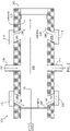
- FIG. 2 is a cross-sectional view of aspects of the housing 130 of the particle concentration measurement device 100 according to an exemplary embodiment.
- the detector 115 is not collocated with the light source 110. Instead, incident light 125 enters the interaction region 145 through the first window 140, interacts with the particle-laden gas 135 in the interaction region 145, exits the interaction region 145 through the second window 150, and is detected by the detector 115.
- the controller 105 may be collocated with the detector 115 or the intensity determined by the detector 115 may be conveyed to the controller 105.
- the cross-section of the housing wall 205 that is cut to reveal the interaction region 145 defined by the windows 140, 150 is shown.
- An inlet 230 for the particle-laden gas 135 and an outlet 235, which may couple to the vacuum source 170 shown in FIG. 1 are shown intersecting the housing 130 (specifically the tube wall 205).
- Clean gas inlets 240 in the housing 130 for the clean gas 180 are also indicated in the housing wall 205.
- the clean gas inlets 240 are angled to direct the clean gas 180 to one of the windows 140, 150.
- the clean gas inlets 240 are formed by cutting straight, rather than at an angle, through the housing wall 205.
- FIG. 4 details exemplary embodiments of the clean gas inlets 240.
- a source of the clean gas 180 is a clean gas source 210 according to exemplary embodiments.
- the clean gas source 210 at each clean gas inlet 240 may be separate or may be coupled to a single source.
- the clean gas source 210 may supply a stream of pressurized air from a dry air tank as the clean gas 180.
- the clean gas source 210 supplying clean gas 180 through the clean gas inlets 240 may be thought of as generating an active clean gas curtain covering each of the windows 140, 150.
- the source of the clean gas 180 is a filter 220 that filters out particles 137 of the fire suppression agent from the particle-laden gas 135 before it enters the clean gas inlets 240.
- the filter 220 resulting in the clean gas 180 in each of the clean gas inlets 240 may be thought of as creating a passive clean gas curtain at each of the windows 140, 150.
- a vacuum e.g., vacuum source 170
- FIG. 3 is a cross-sectional view detailing features of the housing 130 of a particle concentration measurement device 100 according to an exemplary embodiment.
- the view of FIG. 3 details the interaction region 145 and shows an exemplary embodiment of the clean gas inlets 240.
- the housing 130 includes cavities 310 on either side of the path of the particle-laden gas 135 through the interaction region 145.
- Each clean gas inlet 240 is within a circumferential groove 305 that encircles the outer surface of the housing 130.
- Two grooves 305a, 305b (generally referred to as 305) are shown for the exemplary housing 130 of FIG. 3 .
- the two clean gas inlets 240 that are adjacent to the first window 140 are formed in one circumferential groove 305a.
- the filter 220 that is shown at each of these two clean gas inlets 240 filters out particles 137 from the particle-laden gas 135 and creates a curtain of clean gas 180 adjacent to the first window 140.
- the filter 220 at each of these two clean gas inlets 240 adjacent to the window 140 may be part of a circumferential filter 220 that fits in the circumferential groove 305a.
- the two clean gas inlets 240 that are adjacent to the second window 150 are formed in another circumferential groove 305b.
- the filter 220 that is shown at each of these two clean gas inlets 240 filters out particles 137 to create a curtain of clean gas 180 adjacent to the second window 150.
- One circumferential filter 220 may be disposed in the groove 305b. This arrangement of the filter 220 in each groove 305 may prevent the filter 220 from clogging locally over each clean gas inlet 240.
- Different exemplary embodiments for the cross-section A-A through the housing 130 are shown in FIG. 4 .
- FIG. 4 is a cross-sectional view through A-A indicated in FIG. 3 .
- the view in FIG. 4 is a view into the housing 130 from the perspective of the fiber optic cable 120, for example.
- the cross-section A-A is indicated at an axial location of the housing 130 adjacent to the window 140 that reveals the radial positions of clean gas inlets 240 adjacent to the window 140.
- one set of clean gas inlets 240 is adjacent to the window 140 (axially between the window 140 and the inlet 230 for the particle-laden gas 135).
- Another set of clean gas inlets 240 is adjacent to the window 150 (axially between the inlet 230 for the particle-laden gas 135 and the window 150).
- the different radial positions of a given set of clean gas inlets 240 facilitate creating the curtain (i.e., covering) of clean gas 180 at the corresponding window 140, 150.
- FIG. 3 the cross-sectional view at an axial location of the housing 130 adjacent to the window 150 will also reveal radial positions of the clean gas inlets 240.
- the radial arrangement of clean gas inlets 240 adjacent to the window 140 may be the same as or different than the radial arrangement of clean gas inlets 240 adjacent to the window 150.
- the exemplary embodiments shown in FIG. 4 are not intended to be limiting but, instead, to indicate that any number of clean gas inlets 240 in any arrangement may be used adjacent to each window 140, 150.
Landscapes
- Chemical & Material Sciences (AREA)
- Physics & Mathematics (AREA)
- Health & Medical Sciences (AREA)
- Life Sciences & Earth Sciences (AREA)
- Analytical Chemistry (AREA)
- Biochemistry (AREA)
- General Health & Medical Sciences (AREA)
- General Physics & Mathematics (AREA)
- Immunology (AREA)
- Pathology (AREA)
- Dispersion Chemistry (AREA)
- Investigating Or Analysing Materials By Optical Means (AREA)
Abstract
Description
- Exemplary embodiments pertain to the art of fire suppression and, in particular, to a clean gas curtain to prevent particle buildup during a concentration measurement.
- Fire suppression systems deploy agents to extinguish a fire. Halon, a liquified compressed gas that stops the spread of fire by chemically disrupting combustion, is being replaced as a fire-suppression agent due to its contribution to ozone depletion. Alternative fire suppressive agents include dry solid particulates that are dispersed within an environment. The distribution and concentration of the particulates within the environment are factors in the effectiveness of the fire suppression system. As such, measurement of the concentration of a fire suppression agent is an important part of the fire suppression effort using these particulates.
- In one embodiment, a particle concentration measurement system includes a first window and a second window in a housing. The first window and the second window respectively define a first end and a second end of an interaction region between the first window and the second window. A particle-laden gas inlet is through a wall of the housing between the first window and the second window. The particle-laden gas inlet introduces particle-laden gas from an environment that includes particles mixed with other materials into the interaction region. A first set of clean gas inlets is through the wall of the housing. Each clean gas inlet of the first set of clean gas inlets is at a different radial position of the housing and at a first axial location of the housing. A second set of clean gas inlets is through the wall of the housing. Each clean gas inlet of the second set of clean gas inlets is at a different radial position of the housing and at a second axial location of the housing.
- Additionally or alternatively, in this or other embodiments, the first axial location of the housing associated with the first set of clean gas inlets is between the first window and the particle-laden gas inlet.
- Additionally or alternatively, in this or other embodiments, the first set of clean gas inlets is slanted to direct clean gas through the first set of clean gas inlets toward the first window.
- Additionally or alternatively, in this or other embodiments, the second axial location of the housing associated with the second set of clean gas inlets is between the second window and the particle-laden gas inlet.
- Additionally or alternatively, in this or other embodiments, the second set of clean gas inlets is slanted to direct clean gas through the second set of clean gas inlets toward the second window.
- Additionally or alternatively, in this or other embodiments, the system also includes a source of pressurized gas without the particles to introduce the pressurized gas into one or more of the first set of clean gas inlets or into one or more of the second set of clean gas inlets.
- Additionally or alternatively, in this or other embodiments, the system also includes a filter to filter out the particles from the particle-laden gas of the environment prior to its entry into a clean gas inlet of the first set of clean gas inlets or the second set of clean gas inlets.
- Additionally or alternatively, in this or other embodiments, the system also includes a first circumferential groove in an exterior surface of the housing within which the first set of clean gas inlets is formed and a second circumferential groove in the exterior surface of the housing within which the second set of clean gas inlets is formed.
- Additionally or alternatively, in this or other embodiments, the system also includes a light source to emit incident light into the housing via a fiber optic cable. The incident light enters the interaction region through the first window and interacts with the particle-laden gas in the interaction region, a detector configured to detect light intensity following interaction in the interaction region. A controller determines a concentration of the particles in the particle-laden gas in the interaction region based on the intensity measured by the detector.
- Additionally or alternatively, in this or other embodiments, the particles act as a fire suppression agent.
- In another embodiment, a method of assembling a particle concentration measurement system includes disposing a first window and a second window in a housing such that the first window and the second window respectively defining a first end and a second end of an interaction region between the first window and the second window. The method also includes forming a particle-laden gas inlet through a wall of the housing between the first window and the second window. The particle-laden gas inlet introduces particle-laden gas from an environment that includes particles mixed with other materials into the interaction region. A first set of clean gas inlets is formed through the wall of the housing, each clean gas inlet of the first set of clean gas inlets being at a different radial position of the housing and at a first axial location of the housing. A second set of clean gas inlets is formed through the wall of the housing, each clean gas inlet of the second set of clean gas inlets being at a different radial position of the housing and at a second axial location of the housing.
- Additionally or alternatively, in this or other embodiments, the first axial location of the housing associated with the first set of clean gas inlets is between the first window and the particle-laden gas inlet.
- Additionally or alternatively, in this or other embodiments, the forming the first set of clean gas inlets includes creating slanted inlets to direct clean gas through the first set of clean gas inlets toward the first window.
- Additionally or alternatively, in this or other embodiments, the second axial location of the housing associated with the second set of clean gas inlets is between the second window and the particle-laden gas inlet.
- Additionally or alternatively, in this or other embodiments, the forming the second set of clean gas inlets includes creating slanted inlets to direct clean gas through the second set of clean gas inlets toward the second window.
- Additionally or alternatively, in this or other embodiments, the method also includes arranging a source of pressurized gas without the particles to introduce the pressurized gas into one or more of the first set of clean gas inlets or into one or more of the second set of clean gas inlets.
- Additionally or alternatively, in this or other embodiments, the method also includes disposing a filter to filter out the particles from the particle-laden gas of the environment prior to its entry into a clean gas inlet of the first set of clean gas inlets or the second set of clean gas inlets.
- Additionally or alternatively, in this or other embodiments, the method also includes fabricating a first circumferential groove in an exterior surface of the housing within which to form the first set of clean gas inlets and fabricating a second circumferential groove in the exterior surface of the housing within which to form the second set of clean gas inlets.
- Additionally or alternatively, in this or other embodiments, the method also includes arranging a light source to emit incident light into the housing via a fiber optic cable, wherein the incident light enters the interaction region through the first window and interacts with the particle-laden gas in the interaction region, arranging a detector to detect light intensity following interaction in the interaction region, and configuring a controller to determine a concentration of the particles in the particle-laden gas in the interaction region based on the intensity measured by the detector.
- Additionally or alternatively, in this or other embodiments, the particles act as a fire suppression agent.
- The following descriptions should not be considered limiting in any way. With reference to the accompanying drawings, like elements are numbered alike:
-
FIG. 1 is a cross-sectional view of a particle concentration measurement device with a curtain of clean gas at each end of an interaction region according to one or more embodiments; -
FIG. 2 is a cross-sectional view of aspects of the housing of the particle concentration measurement device according to an exemplary embodiment; -
FIG. 3 is a cross-sectional view detailing features of the housing of a particle concentration measurement device according to an exemplary embodiment; and -
FIG. 4 is a view of cross-section A-A indicated inFIG. 3 . - A detailed description of one or more embodiments of the disclosed apparatus and method are presented herein by way of exemplification and not limitation with reference to the Figures.
- As previously noted, the distribution and concentration of dry solid particulates used for fire suppression can affect the result of the suppressive effort. Thus, a fire suppression agent concentration measurement device may be used to measure concentration in real time. A set of such devices may be used in different areas of a given environment to also determine distribution. The measurements may be used to control the release of additional fire suppression agent as needed, for example.
- One approach to measuring the concentration of fire suppression agent in the environment involves transmitting light into an interaction region in which the light interacts with a sample of gas from the environment. The interaction region may be defined by two windows. The introduction of light into the interaction region is through a first window. The intensity of the light that has interacted with the gas from the environment is measured, and a decrease in the intensity is correlated to a concentration of the fire suppression agent in the gas. Over time, the introduction of gas with fire suppressive particles into the interaction region between the two windows may result in particle buildup on the windows. This buildup impedes light transmission through the windows, thus preventing the accurate measurement of the concentration of the fire suppression agent.
- Embodiments of the systems and methods detailed herein relate to a clean gas curtain to prevent particle buildup during a concentration measurement. As detailed, the clean gas curtain is formed at each of the two ends of the interaction region, adjacent to each window. This clean gas curtain is formed, according to alternate embodiments, in order to prevent particles of the suppressive agent from contacting and adhering to the windows. According to one exemplary embodiment, a clean gas source introduces air at the two ends of the interaction region. According to another exemplary embodiment, a filter filters out the fire suppressant particles prior to gas entering the two ends of the interaction region. The clean gas curtain addresses the issues of inaccuracy created by particle buildup on the windows without requiring cleaning.
-
FIG. 1 is a cross-sectional view of a particleconcentration measurement device 100 with a curtain ofclean gas 180 at each end of aninteraction region 145 according to one or more embodiments. The particleconcentration measurement device 100 is disposed in an environment in which a solid particle fire suppression agent is dispersed, for example. Theparticles 137 mix with air and other materials in the environment to create particle-laden gas 135. The particleconcentration measurement device 100 measures the concentration of theparticles 137 of fire suppression agent in the particle-laden gas 135 in the environment. Alight source 110 emitsincident light 125 via afiber optic cable 120 into a tube-like housing 130. - The
housing 130 includes aninteraction region 145 that is defined by a lens orwindow 140 on one end and another lens orwindow 150 on the other end. The particle-laden gas 135 from the environment is introduce into theinteraction region 145 of the tube where it interacts with the incident light 125 that enters theinteraction region 145 through thefirst window 140. The light exits theinteraction region 145 via thesecond window 150 and is reflected by amirror 160 according to the exemplary embodiment. Reflected light 165 then re-enters theinteraction region 145 through thesecond window 150 and exits thehousing 130 through thefirst window 140. The reflected light 165 and, more specifically, intensity of the reflected light 165 is detected by adetector 115. Acontroller 105 then uses the measured intensity of the reflected light 165 to determine the concentration of theparticles 137 of fire suppression agent in the particle-laden gas 135. A mapping of measured intensity to concentration may be in the form of a look-up table, for example. - As shown, a
vacuum source 170 may be used to pull the particle-laden gas 135 out of theinteraction region 145 of thehousing 130. According to prior arrangements, any lingeringparticles 137 of the fire suppression agent remaining in theinteraction region 145 may have come into contact with one of thewindows clean gas 180 according to one or more embodiments. Specifically,clean gas 180, which does not include anyparticles 137 of the fire suppression agent or includes a much-reduced concentration ofparticles 137 of the fire suppression agent, as compared to the particle-laden gas 135, is introduced into theinteraction region 145 adjacent to each of thewindows FIG. 1 . The curtain ofclean gas 180 adjacent to thewindows particles 137 from building up on thewindows -
FIG. 2 is a cross-sectional view of aspects of thehousing 130 of the particleconcentration measurement device 100 according to an exemplary embodiment. According to the exemplary embodiment shown inFIG. 2 , there is nomirror 160, and thedetector 115 is not collocated with thelight source 110. Instead,incident light 125 enters theinteraction region 145 through thefirst window 140, interacts with the particle-laden gas 135 in theinteraction region 145, exits theinteraction region 145 through thesecond window 150, and is detected by thedetector 115. Thecontroller 105 may be collocated with thedetector 115 or the intensity determined by thedetector 115 may be conveyed to thecontroller 105. - The cross-section of the
housing wall 205 that is cut to reveal theinteraction region 145 defined by thewindows inlet 230 for the particle-laden gas 135 and anoutlet 235, which may couple to thevacuum source 170 shown inFIG. 1 , are shown intersecting the housing 130 (specifically the tube wall 205).Clean gas inlets 240 in thehousing 130 for theclean gas 180 are also indicated in thehousing wall 205. According to the exemplary embodiment shown inFIG. 2 , theclean gas inlets 240 are angled to direct theclean gas 180 to one of thewindows clean gas inlets 240 are formed by cutting straight, rather than at an angle, through thehousing wall 205.FIG. 4 details exemplary embodiments of theclean gas inlets 240. - As shown in
FIG. 2 , a source of theclean gas 180 is aclean gas source 210 according to exemplary embodiments. Theclean gas source 210 at eachclean gas inlet 240 may be separate or may be coupled to a single source. Theclean gas source 210 may supply a stream of pressurized air from a dry air tank as theclean gas 180. Theclean gas source 210 supplyingclean gas 180 through theclean gas inlets 240 may be thought of as generating an active clean gas curtain covering each of thewindows FIG. 3 , the source of theclean gas 180 is afilter 220 that filters outparticles 137 of the fire suppression agent from the particle-laden gas 135 before it enters theclean gas inlets 240. Thefilter 220 resulting in theclean gas 180 in each of theclean gas inlets 240 may be thought of as creating a passive clean gas curtain at each of thewindows filters 220 at eachclean gas inlet 240. -
FIG. 3 is a cross-sectional view detailing features of thehousing 130 of a particleconcentration measurement device 100 according to an exemplary embodiment. The view ofFIG. 3 details theinteraction region 145 and shows an exemplary embodiment of theclean gas inlets 240. Thehousing 130 includes cavities 310 on either side of the path of the particle-laden gas 135 through theinteraction region 145. Eachclean gas inlet 240 is within a circumferential groove 305 that encircles the outer surface of thehousing 130. Twogrooves 305a, 305b (generally referred to as 305) are shown for theexemplary housing 130 ofFIG. 3 . - That is, the two
clean gas inlets 240 that are adjacent to thefirst window 140 are formed in one circumferential groove 305a. Thefilter 220 that is shown at each of these twoclean gas inlets 240 filters outparticles 137 from the particle-laden gas 135 and creates a curtain ofclean gas 180 adjacent to thefirst window 140. Thefilter 220 at each of these twoclean gas inlets 240 adjacent to thewindow 140 may be part of acircumferential filter 220 that fits in the circumferential groove 305a. Similarly, the twoclean gas inlets 240 that are adjacent to thesecond window 150 are formed in anothercircumferential groove 305b. Thefilter 220 that is shown at each of these twoclean gas inlets 240 filters outparticles 137 to create a curtain ofclean gas 180 adjacent to thesecond window 150. Onecircumferential filter 220 may be disposed in thegroove 305b. This arrangement of thefilter 220 in each groove 305 may prevent thefilter 220 from clogging locally over eachclean gas inlet 240. Different exemplary embodiments for the cross-section A-A through thehousing 130 are shown inFIG. 4 . -
FIG. 4 is a cross-sectional view through A-A indicated inFIG. 3 . The view inFIG. 4 is a view into thehousing 130 from the perspective of thefiber optic cable 120, for example. The cross-section A-A is indicated at an axial location of thehousing 130 adjacent to thewindow 140 that reveals the radial positions ofclean gas inlets 240 adjacent to thewindow 140. AsFIGS. 1-3 indicate, one set ofclean gas inlets 240 is adjacent to the window 140 (axially between thewindow 140 and theinlet 230 for the particle-laden gas 135). Another set ofclean gas inlets 240 is adjacent to the window 150 (axially between theinlet 230 for the particle-laden gas 135 and the window 150). The different radial positions of a given set ofclean gas inlets 240, according to theexemplary embodiments FIG. 4 and additional embodiments, facilitate creating the curtain (i.e., covering) ofclean gas 180 at thecorresponding window - Four
exemplary embodiments FIG. 3 , the cross-sectional view at an axial location of thehousing 130 adjacent to thewindow 150 will also reveal radial positions of theclean gas inlets 240. According to alternate embodiments, the radial arrangement ofclean gas inlets 240 adjacent to thewindow 140 may be the same as or different than the radial arrangement ofclean gas inlets 240 adjacent to thewindow 150. The exemplary embodiments shown inFIG. 4 are not intended to be limiting but, instead, to indicate that any number ofclean gas inlets 240 in any arrangement may be used adjacent to eachwindow - The terminology used herein is for the purpose of describing particular embodiments only and is not intended to be limiting of the present disclosure. As used herein, the singular forms "a", "an" and "the" are intended to include the plural forms as well, unless the context clearly indicates otherwise. It will be further understood that the terms "comprises" and/or "comprising," when used in this specification, specify the presence of stated features, integers, steps, operations, elements, and/or components, but do not preclude the presence or addition of one or more other features, integers, steps, operations, element components, and/or groups thereof.
- While the present disclosure has been described with reference to an exemplary embodiment or embodiments, it will be understood by those skilled in the art that various changes may be made and equivalents may be substituted for elements thereof without departing from the scope of the present disclosure. In addition, many modifications may be made to adapt a particular situation or material to the teachings of the present disclosure without departing from the essential scope thereof. Therefore, it is intended that the present disclosure not be limited to the particular embodiment disclosed as the best mode contemplated for carrying out this present disclosure, but that the present disclosure will include all embodiments falling within the scope of the claims.
Claims (15)
- A particle concentration measurement system comprising:a first window and a second window in a housing, the first window and the second window respectively defining a first end and a second end of an interaction region between the first window and the second window;a particle-laden gas inlet through a wall of the housing between the first window and the second window, the particle-laden gas inlet being configured to introduce particle-laden gas from an environment that includes particles mixed with other materials into the interaction region;a first set of clean gas inlets through the wall of the housing, each clean gas inlet of the first set of clean gas inlets being at a different radial position of the housing and at a first axial location of the housing; anda second set of clean gas inlets through the wall of the housing, each clean gas inlet of the second set of clean gas inlets being at a different radial position of the housing and at a second axial location of the housing.
- The system according to claim 1, wherein the first axial location of the housing associated with the first set of clean gas inlets is between the first window and the particle-laden gas inlet.
- The system according to claim 1 or 2, wherein the first set of clean gas inlets is slanted to direct clean gas through the first set of clean gas inlets toward the first window.
- The system according to claim 1, 2 or 3, wherein the second axial location of the housing associated with the second set of clean gas inlets is between the second window and the particle-laden gas inlet.
- The system according to any preceding claim, wherein the second set of clean gas inlets is slanted to direct clean gas through the second set of clean gas inlets toward the second window.
- The system according to any preceding claim, further comprising a source of pressurized gas without the particles configured to introduce the pressurized gas into one or more of the first set of clean gas inlets and/or into one or more of the second set of clean gas inlets.
- The system according to any preceding claim, further comprising a filter configured to filter out the particles from the particle-laden gas of the environment prior to its entry into a clean gas inlet of the first set of clean gas inlets and/or the second set of clean gas inlets.
- The system according to any preceding claim, further comprising a first circumferential groove in an exterior surface of the housing within which the first set of clean gas inlets is formed and a second circumferential groove in the exterior surface of the housing within which the second set of clean gas inlets is formed.
- The system according to any preceding claim, further comprising a light source configured to emit incident light into the housing via a fiber optic cable, wherein the incident light enters the interaction region through the first window and interacts with the particle-laden gas in the interaction region, a detector configured to detect light intensity following interaction in the interaction region, and a controller configured to determine a concentration of the particles in the particle-laden gas in the interaction region based on the intensity measured by the detector.
- The system according to any preceding claim, wherein the particles act as a fire suppression agent.
- A method of assembling a particle concentration measurement system, the method comprising:disposing a first window and a second window in a housing such that the first window and the second window respectively define a first end and a second end of an interaction region between the first window and the second window;forming a particle-laden gas inlet through a wall of the housing between the first window and the second window, the particle-laden gas inlet being configured to introduce particle-laden gas from an environment that includes particles mixed with other materials into the interaction region;forming a first set of clean gas inlets through the wall of the housing, each clean gas inlet of the first set of clean gas inlets being at a different radial position of the housing and at a first axial location of the housing; andforming a second set of clean gas inlets through the wall of the housing, each clean gas inlet of the second set of clean gas inlets being at a different radial position of the housing and at a second axial location of the housing.
- The method according to claim 11, further comprising arranging a source of pressurized gas without the particles to introduce the pressurized gas into one or more of the first set of clean gas inlets or into one or more of the second set of clean gas inlets.
- The method according to claim 11 or 12, further comprising disposing a filter to filter out the particles from the particle-laden gas of the environment prior to its entry into a clean gas inlet of the first set of clean gas inlets or the second set of clean gas inlets.
- The method according to claim 11, 12 or 13, further comprising arranging a light source to emit incident light into the housing via a fiber optic cable, wherein the incident light enters the interaction region through the first window and interacts with the particle-laden gas in the interaction region, arranging a detector to detect light intensity following interaction in the interaction region, and configuring a controller to determine a concentration of the particles in the particle-laden gas in the interaction region based on the intensity measured by the detector.
- The method according to any one of claims 11-14, wherein the particles act as a fire suppression agent.
Applications Claiming Priority (1)
| Application Number | Priority Date | Filing Date | Title |
|---|---|---|---|
| US16/951,056 US11781969B2 (en) | 2020-11-18 | 2020-11-18 | Clean gas curtain to prevent particle buildup during concentration measurement |
Publications (2)
| Publication Number | Publication Date |
|---|---|
| EP4001895A1 true EP4001895A1 (en) | 2022-05-25 |
| EP4001895B1 EP4001895B1 (en) | 2025-11-26 |
Family
ID=78821794
Family Applications (1)
| Application Number | Title | Priority Date | Filing Date |
|---|---|---|---|
| EP21203295.7A Active EP4001895B1 (en) | 2020-11-18 | 2021-10-18 | Clean gas curtain to prevent particle buildup during concentration measurement |
Country Status (3)
| Country | Link |
|---|---|
| US (1) | US11781969B2 (en) |
| EP (1) | EP4001895B1 (en) |
| ES (1) | ES3057126T3 (en) |
Families Citing this family (2)
| Publication number | Priority date | Publication date | Assignee | Title |
|---|---|---|---|---|
| CN119290699B (en) * | 2024-12-13 | 2025-04-18 | 中国科学技术大学 | Airflow protection type optical fiber probe, powder concentration measurement system and method |
| CN119958955B (en) * | 2025-04-08 | 2025-07-04 | 内蒙古国华准格尔发电有限责任公司 | A high temperature gaseous pollutant measuring device |
Citations (4)
| Publication number | Priority date | Publication date | Assignee | Title |
|---|---|---|---|---|
| US3628028A (en) * | 1968-03-01 | 1971-12-14 | Honeywell Inc | Window cleaning apparatus for photometric instruments |
| EP0064200B1 (en) * | 1981-04-24 | 1987-07-08 | Measurex Corporation | Apparatus for analyzing a gas |
| US4896047A (en) * | 1988-04-11 | 1990-01-23 | Westinghouse Electric Corp. | Method and apparatus of periodically obtaining accurate opacity monitor readings of an exhaust gas stream |
| EP3258241A2 (en) * | 2017-09-14 | 2017-12-20 | Sensirion AG | Particulate matter sensor device |
Family Cites Families (20)
| Publication number | Priority date | Publication date | Assignee | Title |
|---|---|---|---|---|
| US1937721A (en) * | 1929-09-05 | 1933-12-05 | Simon Alfred Walter | Apparatus for measuring dust concentration |
| US1937722A (en) * | 1931-08-14 | 1933-12-05 | Simon Alfred Walter | Dust and smoke density measuring device |
| US3200254A (en) | 1962-03-19 | 1965-08-10 | Gen Electric | Photosensitive detector for airborne particles |
| US3251999A (en) * | 1962-11-26 | 1966-05-17 | Oscar Mayer & Company Inc | Photoelectric system for measuring the density of smoke |
| US4784491A (en) * | 1986-06-03 | 1988-11-15 | General Electric Company | System to protect optics against dirty environments |
| US4966462A (en) | 1989-02-15 | 1990-10-30 | The United States Of America As Represented By The United States Department Of Energy | Series cell light extinction monitor |
| US5191878A (en) * | 1990-04-12 | 1993-03-09 | Olympus Optical Co., Ltd. | Endoscope device |
| DE4220701C2 (en) * | 1991-08-02 | 2001-02-08 | Olympus Optical Co | Endoscope cleaning device |
| US5807750A (en) * | 1995-05-02 | 1998-09-15 | Air Instruments And Measurements, Inc. | Optical substance analyzer and data processor |
| GB2309076B (en) | 1996-01-10 | 1999-08-11 | Kidde Fire Protection Ltd | Particle separation and detection apparatus |
| WO1999064841A1 (en) | 1998-06-12 | 1999-12-16 | Rose Thomas H | Backscatter instrument for monitoring particulate levels in a gas stream |
| US6421127B1 (en) * | 1999-07-19 | 2002-07-16 | American Air Liquide, Inc. | Method and system for preventing deposition on an optical component in a spectroscopic sensor |
| ES2315262T3 (en) | 2001-08-17 | 2009-04-01 | Mcdermott Technology, Inc. | SMOKE DETECTOR OF LIGHT DISPERSION. |
| US7319524B2 (en) | 2005-03-28 | 2008-01-15 | Honeywell International, Inc. | Air purged optical densitometer |
| EP2169385A1 (en) * | 2008-09-24 | 2010-03-31 | Siemens Aktiengesellschaft | An optical measuring head for a duct gas monitoring system |
| US8004684B2 (en) | 2009-04-09 | 2011-08-23 | Kidde Technologies, Inc. | Sensor head for a dry powder agent |
| MY167512A (en) | 2009-07-07 | 2018-09-04 | Xtralis Technologies Ltd | Chamber condition |
| EP2507609A1 (en) * | 2009-12-04 | 2012-10-10 | Siemens Aktiengesellschaft | Method for determining the optical measurement path length in a duct gas monitoring system |
| US9709491B1 (en) * | 2016-03-28 | 2017-07-18 | The United States Of America | System and method for measuring aerosol or trace species |
| EP3781929B1 (en) * | 2018-04-20 | 2022-06-08 | Flo2R Aps | Gas analysis system and method |
-
2020
- 2020-11-18 US US16/951,056 patent/US11781969B2/en active Active
-
2021
- 2021-10-18 ES ES21203295T patent/ES3057126T3/en active Active
- 2021-10-18 EP EP21203295.7A patent/EP4001895B1/en active Active
Patent Citations (4)
| Publication number | Priority date | Publication date | Assignee | Title |
|---|---|---|---|---|
| US3628028A (en) * | 1968-03-01 | 1971-12-14 | Honeywell Inc | Window cleaning apparatus for photometric instruments |
| EP0064200B1 (en) * | 1981-04-24 | 1987-07-08 | Measurex Corporation | Apparatus for analyzing a gas |
| US4896047A (en) * | 1988-04-11 | 1990-01-23 | Westinghouse Electric Corp. | Method and apparatus of periodically obtaining accurate opacity monitor readings of an exhaust gas stream |
| EP3258241A2 (en) * | 2017-09-14 | 2017-12-20 | Sensirion AG | Particulate matter sensor device |
Also Published As
| Publication number | Publication date |
|---|---|
| ES3057126T3 (en) | 2026-02-26 |
| US20220155216A1 (en) | 2022-05-19 |
| EP4001895B1 (en) | 2025-11-26 |
| US11781969B2 (en) | 2023-10-10 |
Similar Documents
| Publication | Publication Date | Title |
|---|---|---|
| EP4001895B1 (en) | Clean gas curtain to prevent particle buildup during concentration measurement | |
| US10525458B2 (en) | Clean air device and air cleaning unit inspecting method | |
| EP0698262A1 (en) | Smoke detector sensitivity testing apparatus | |
| CN102473339B (en) | Room regulates | |
| US7766638B2 (en) | Tablet production method and tablet production apparatus | |
| US10761013B2 (en) | Method and device for cleaning an optical entrance window of a fire alarm | |
| JP6743105B2 (en) | Distance measuring device | |
| JP2000503120A (en) | Particle separation and detection device | |
| EP4160185A1 (en) | Compressed gas cleaning of windows in particle concentration measurement device | |
| CN109307647A (en) | Measurement is especially used for motor vehicles, the measuring device of the thin particulate matter at least one volume of air for vehicle | |
| CN113795749B (en) | Multi-channel infrared gas sensor with compensation for mechanical disturbance | |
| KR102158142B1 (en) | device for measuring dust by different particle size in chimney | |
| ITSV960040A1 (en) | METHOD AND DEVICE FOR THE CONTROL WITHOUT DIRECT CONTACT OF THE HEADS OF THE CIGARETTES, OR SIMILAR. | |
| US11442005B2 (en) | Gas analyser system | |
| JP2015505057A (en) | Reflective probe | |
| EP4155711A1 (en) | Omni-directional particulate extraction inlet | |
| JP2009024433A (en) | System for monitoring and scatter-preventing fibrous dust of asbestos and the like, generated by removing work of spraying material containing asbestos or alternative fibers to asbestos, or material containing asbestos or alternative fibers to asbestos | |
| KR20120063238A (en) | Particle measuring apparatus | |
| EP3926327B1 (en) | Fire extinguishing agent concentration measuring system and method | |
| JP2016017925A (en) | Dust leakage monitoring system | |
| KR102223149B1 (en) | Apparatus for diluting exhaust gas | |
| US11280731B2 (en) | Fire extinguishing agent concentration measuring system and method of measuring a fire extinguishing agent within an environment | |
| JP2005276603A (en) | Bar type static eliminator | |
| JP7013147B2 (en) | Smoke detector | |
| JP7486462B2 (en) | Particle measurement equipment |
Legal Events
| Date | Code | Title | Description |
|---|---|---|---|
| PUAI | Public reference made under article 153(3) epc to a published international application that has entered the european phase |
Free format text: ORIGINAL CODE: 0009012 |
|
| STAA | Information on the status of an ep patent application or granted ep patent |
Free format text: STATUS: THE APPLICATION HAS BEEN PUBLISHED |
|
| AK | Designated contracting states |
Kind code of ref document: A1 Designated state(s): AL AT BE BG CH CY CZ DE DK EE ES FI FR GB GR HR HU IE IS IT LI LT LU LV MC MK MT NL NO PL PT RO RS SE SI SK SM TR |
|
| STAA | Information on the status of an ep patent application or granted ep patent |
Free format text: STATUS: REQUEST FOR EXAMINATION WAS MADE |
|
| 17P | Request for examination filed |
Effective date: 20221125 |
|
| RBV | Designated contracting states (corrected) |
Designated state(s): AL AT BE BG CH CY CZ DE DK EE ES FI FR GB GR HR HU IE IS IT LI LT LU LV MC MK MT NL NO PL PT RO RS SE SI SK SM TR |
|
| STAA | Information on the status of an ep patent application or granted ep patent |
Free format text: STATUS: EXAMINATION IS IN PROGRESS |
|
| 17Q | First examination report despatched |
Effective date: 20240327 |
|
| GRAP | Despatch of communication of intention to grant a patent |
Free format text: ORIGINAL CODE: EPIDOSNIGR1 |
|
| STAA | Information on the status of an ep patent application or granted ep patent |
Free format text: STATUS: GRANT OF PATENT IS INTENDED |
|
| RIC1 | Information provided on ipc code assigned before grant |
Ipc: G01N 1/42 20060101ALN20250411BHEP Ipc: G01N 1/08 20060101ALN20250411BHEP Ipc: G01N 15/00 20060101ALN20250411BHEP Ipc: G01N 15/06 20060101AFI20250411BHEP |
|
| RIC1 | Information provided on ipc code assigned before grant |
Ipc: G01N 1/42 20060101ALN20250430BHEP Ipc: G01N 1/08 20060101ALN20250430BHEP Ipc: G01N 15/00 20060101ALN20250430BHEP Ipc: G01N 15/06 20060101AFI20250430BHEP |
|
| RIC1 | Information provided on ipc code assigned before grant |
Ipc: G01N 1/42 20060101ALN20250507BHEP Ipc: G01N 1/08 20060101ALN20250507BHEP Ipc: G01N 15/00 20060101ALN20250507BHEP Ipc: G01N 15/06 20060101AFI20250507BHEP |
|
| INTG | Intention to grant announced |
Effective date: 20250519 |
|
| GRAS | Grant fee paid |
Free format text: ORIGINAL CODE: EPIDOSNIGR3 |
|
| GRAA | (expected) grant |
Free format text: ORIGINAL CODE: 0009210 |
|
| STAA | Information on the status of an ep patent application or granted ep patent |
Free format text: STATUS: THE PATENT HAS BEEN GRANTED |
|
| AK | Designated contracting states |
Kind code of ref document: B1 Designated state(s): AL AT BE BG CH CY CZ DE DK EE ES FI FR GB GR HR HU IE IS IT LI LT LU LV MC MK MT NL NO PL PT RO RS SE SI SK SM TR |
|
| REG | Reference to a national code |
Ref country code: CH Ref legal event code: F10 Free format text: ST27 STATUS EVENT CODE: U-0-0-F10-F00 (AS PROVIDED BY THE NATIONAL OFFICE) Effective date: 20251126 Ref country code: GB Ref legal event code: FG4D |
|
| REG | Reference to a national code |
Ref country code: IE Ref legal event code: FG4D |
|
| REG | Reference to a national code |
Ref country code: DE Ref legal event code: R096 Ref document number: 602021042963 Country of ref document: DE |
|
| REG | Reference to a national code |
Ref country code: ES Ref legal event code: FG2A Ref document number: 3057126 Country of ref document: ES Kind code of ref document: T3 Effective date: 20260226 |
|
| REG | Reference to a national code |
Ref country code: NL Ref legal event code: MP Effective date: 20251126 |
|
| REG | Reference to a national code |
Ref country code: LT Ref legal event code: MG9D |
|
| PG25 | Lapsed in a contracting state [announced via postgrant information from national office to epo] |
Ref country code: NO Free format text: LAPSE BECAUSE OF FAILURE TO SUBMIT A TRANSLATION OF THE DESCRIPTION OR TO PAY THE FEE WITHIN THE PRESCRIBED TIME-LIMIT Effective date: 20260226 |
|
| PG25 | Lapsed in a contracting state [announced via postgrant information from national office to epo] |
Ref country code: AT Free format text: LAPSE BECAUSE OF FAILURE TO SUBMIT A TRANSLATION OF THE DESCRIPTION OR TO PAY THE FEE WITHIN THE PRESCRIBED TIME-LIMIT Effective date: 20251126 Ref country code: FI Free format text: LAPSE BECAUSE OF FAILURE TO SUBMIT A TRANSLATION OF THE DESCRIPTION OR TO PAY THE FEE WITHIN THE PRESCRIBED TIME-LIMIT Effective date: 20251126 Ref country code: HR Free format text: LAPSE BECAUSE OF FAILURE TO SUBMIT A TRANSLATION OF THE DESCRIPTION OR TO PAY THE FEE WITHIN THE PRESCRIBED TIME-LIMIT Effective date: 20251126 |
|
| REG | Reference to a national code |
Ref country code: AT Ref legal event code: MK05 Ref document number: 1861492 Country of ref document: AT Kind code of ref document: T Effective date: 20251126 |
|
| PG25 | Lapsed in a contracting state [announced via postgrant information from national office to epo] |
Ref country code: NL Free format text: LAPSE BECAUSE OF FAILURE TO SUBMIT A TRANSLATION OF THE DESCRIPTION OR TO PAY THE FEE WITHIN THE PRESCRIBED TIME-LIMIT Effective date: 20251126 |
|
| PG25 | Lapsed in a contracting state [announced via postgrant information from national office to epo] |
Ref country code: RS Free format text: LAPSE BECAUSE OF FAILURE TO SUBMIT A TRANSLATION OF THE DESCRIPTION OR TO PAY THE FEE WITHIN THE PRESCRIBED TIME-LIMIT Effective date: 20260226 |
|
| PG25 | Lapsed in a contracting state [announced via postgrant information from national office to epo] |
Ref country code: IS Free format text: LAPSE BECAUSE OF FAILURE TO SUBMIT A TRANSLATION OF THE DESCRIPTION OR TO PAY THE FEE WITHIN THE PRESCRIBED TIME-LIMIT Effective date: 20260326 |
|
| PG25 | Lapsed in a contracting state [announced via postgrant information from national office to epo] |
Ref country code: PT Free format text: LAPSE BECAUSE OF FAILURE TO SUBMIT A TRANSLATION OF THE DESCRIPTION OR TO PAY THE FEE WITHIN THE PRESCRIBED TIME-LIMIT Effective date: 20260326 |
|
| PG25 | Lapsed in a contracting state [announced via postgrant information from national office to epo] |
Ref country code: PL Free format text: LAPSE BECAUSE OF FAILURE TO SUBMIT A TRANSLATION OF THE DESCRIPTION OR TO PAY THE FEE WITHIN THE PRESCRIBED TIME-LIMIT Effective date: 20251126 |
|
| PG25 | Lapsed in a contracting state [announced via postgrant information from national office to epo] |
Ref country code: LV Free format text: LAPSE BECAUSE OF FAILURE TO SUBMIT A TRANSLATION OF THE DESCRIPTION OR TO PAY THE FEE WITHIN THE PRESCRIBED TIME-LIMIT Effective date: 20251126 |
|
| PG25 | Lapsed in a contracting state [announced via postgrant information from national office to epo] |
Ref country code: BG Free format text: LAPSE BECAUSE OF FAILURE TO SUBMIT A TRANSLATION OF THE DESCRIPTION OR TO PAY THE FEE WITHIN THE PRESCRIBED TIME-LIMIT Effective date: 20251126 |
|
| PG25 | Lapsed in a contracting state [announced via postgrant information from national office to epo] |
Ref country code: LT Free format text: LAPSE BECAUSE OF FAILURE TO SUBMIT A TRANSLATION OF THE DESCRIPTION OR TO PAY THE FEE WITHIN THE PRESCRIBED TIME-LIMIT Effective date: 20251126 |
|
| PG25 | Lapsed in a contracting state [announced via postgrant information from national office to epo] |
Ref country code: SM Free format text: LAPSE BECAUSE OF FAILURE TO SUBMIT A TRANSLATION OF THE DESCRIPTION OR TO PAY THE FEE WITHIN THE PRESCRIBED TIME-LIMIT Effective date: 20251126 |
|
| PG25 | Lapsed in a contracting state [announced via postgrant information from national office to epo] |
Ref country code: DK Free format text: LAPSE BECAUSE OF FAILURE TO SUBMIT A TRANSLATION OF THE DESCRIPTION OR TO PAY THE FEE WITHIN THE PRESCRIBED TIME-LIMIT Effective date: 20251126 |
|
| PG25 | Lapsed in a contracting state [announced via postgrant information from national office to epo] |
Ref country code: IT Free format text: LAPSE BECAUSE OF FAILURE TO SUBMIT A TRANSLATION OF THE DESCRIPTION OR TO PAY THE FEE WITHIN THE PRESCRIBED TIME-LIMIT Effective date: 20251126 |
|
| PG25 | Lapsed in a contracting state [announced via postgrant information from national office to epo] |
Ref country code: EE Free format text: LAPSE BECAUSE OF FAILURE TO SUBMIT A TRANSLATION OF THE DESCRIPTION OR TO PAY THE FEE WITHIN THE PRESCRIBED TIME-LIMIT Effective date: 20251126 |
|
| PG25 | Lapsed in a contracting state [announced via postgrant information from national office to epo] |
Ref country code: CZ Free format text: LAPSE BECAUSE OF FAILURE TO SUBMIT A TRANSLATION OF THE DESCRIPTION OR TO PAY THE FEE WITHIN THE PRESCRIBED TIME-LIMIT Effective date: 20251126 |
|
| PG25 | Lapsed in a contracting state [announced via postgrant information from national office to epo] |
Ref country code: SK Free format text: LAPSE BECAUSE OF FAILURE TO SUBMIT A TRANSLATION OF THE DESCRIPTION OR TO PAY THE FEE WITHIN THE PRESCRIBED TIME-LIMIT Effective date: 20251126 |
|
| PG25 | Lapsed in a contracting state [announced via postgrant information from national office to epo] |
Ref country code: SE Free format text: LAPSE BECAUSE OF FAILURE TO SUBMIT A TRANSLATION OF THE DESCRIPTION OR TO PAY THE FEE WITHIN THE PRESCRIBED TIME-LIMIT Effective date: 20251126 |