EP4001746A1 - Luminescent body - Google Patents
Luminescent body Download PDFInfo
- Publication number
- EP4001746A1 EP4001746A1 EP21208857.9A EP21208857A EP4001746A1 EP 4001746 A1 EP4001746 A1 EP 4001746A1 EP 21208857 A EP21208857 A EP 21208857A EP 4001746 A1 EP4001746 A1 EP 4001746A1
- Authority
- EP
- European Patent Office
- Prior art keywords
- walls
- coating portion
- outer coating
- body according
- casing
- Prior art date
- Legal status (The legal status is an assumption and is not a legal conclusion. Google has not performed a legal analysis and makes no representation as to the accuracy of the status listed.)
- Granted
Links
Images


Classifications
-
- F—MECHANICAL ENGINEERING; LIGHTING; HEATING; WEAPONS; BLASTING
- F21—LIGHTING
- F21V—FUNCTIONAL FEATURES OR DETAILS OF LIGHTING DEVICES OR SYSTEMS THEREOF; STRUCTURAL COMBINATIONS OF LIGHTING DEVICES WITH OTHER ARTICLES, NOT OTHERWISE PROVIDED FOR
- F21V3/00—Globes; Bowls; Cover glasses
- F21V3/04—Globes; Bowls; Cover glasses characterised by materials, surface treatments or coatings
-
- F—MECHANICAL ENGINEERING; LIGHTING; HEATING; WEAPONS; BLASTING
- F21—LIGHTING
- F21V—FUNCTIONAL FEATURES OR DETAILS OF LIGHTING DEVICES OR SYSTEMS THEREOF; STRUCTURAL COMBINATIONS OF LIGHTING DEVICES WITH OTHER ARTICLES, NOT OTHERWISE PROVIDED FOR
- F21V15/00—Protecting lighting devices from damage
- F21V15/01—Housings, e.g. material or assembling of housing parts
-
- F—MECHANICAL ENGINEERING; LIGHTING; HEATING; WEAPONS; BLASTING
- F21—LIGHTING
- F21V—FUNCTIONAL FEATURES OR DETAILS OF LIGHTING DEVICES OR SYSTEMS THEREOF; STRUCTURAL COMBINATIONS OF LIGHTING DEVICES WITH OTHER ARTICLES, NOT OTHERWISE PROVIDED FOR
- F21V3/00—Globes; Bowls; Cover glasses
- F21V3/04—Globes; Bowls; Cover glasses characterised by materials, surface treatments or coatings
- F21V3/10—Globes; Bowls; Cover glasses characterised by materials, surface treatments or coatings characterised by coatings
-
- G—PHYSICS
- G09—EDUCATION; CRYPTOGRAPHY; DISPLAY; ADVERTISING; SEALS
- G09F—DISPLAYING; ADVERTISING; SIGNS; LABELS OR NAME-PLATES; SEALS
- G09F13/00—Illuminated signs; Luminous advertising
- G09F13/04—Signs, boards or panels, illuminated from behind the insignia
- G09F13/0404—Signs, boards or panels, illuminated from behind the insignia the light source being enclosed in a box forming the character of the sign
-
- G—PHYSICS
- G09—EDUCATION; CRYPTOGRAPHY; DISPLAY; ADVERTISING; SEALS
- G09F—DISPLAYING; ADVERTISING; SIGNS; LABELS OR NAME-PLATES; SEALS
- G09F13/00—Illuminated signs; Luminous advertising
- G09F13/04—Signs, boards or panels, illuminated from behind the insignia
- G09F13/0413—Frames or casing structures therefor
-
- F—MECHANICAL ENGINEERING; LIGHTING; HEATING; WEAPONS; BLASTING
- F21—LIGHTING
- F21V—FUNCTIONAL FEATURES OR DETAILS OF LIGHTING DEVICES OR SYSTEMS THEREOF; STRUCTURAL COMBINATIONS OF LIGHTING DEVICES WITH OTHER ARTICLES, NOT OTHERWISE PROVIDED FOR
- F21V15/00—Protecting lighting devices from damage
- F21V15/01—Housings, e.g. material or assembling of housing parts
- F21V15/012—Housings with variable shape or dimensions, e.g. by means of elastically deformable materials or by movement of parts forming telescopic extensions of the housing body
-
- F—MECHANICAL ENGINEERING; LIGHTING; HEATING; WEAPONS; BLASTING
- F21—LIGHTING
- F21W—INDEXING SCHEME ASSOCIATED WITH SUBCLASSES F21K, F21L, F21S and F21V, RELATING TO USES OR APPLICATIONS OF LIGHTING DEVICES OR SYSTEMS
- F21W2121/00—Use or application of lighting devices or systems for decorative purposes, not provided for in codes F21W2102/00 – F21W2107/00
-
- F—MECHANICAL ENGINEERING; LIGHTING; HEATING; WEAPONS; BLASTING
- F21—LIGHTING
- F21Y—INDEXING SCHEME ASSOCIATED WITH SUBCLASSES F21K, F21L, F21S and F21V, RELATING TO THE FORM OR THE KIND OF THE LIGHT SOURCES OR OF THE COLOUR OF THE LIGHT EMITTED
- F21Y2105/00—Planar light sources
-
- G—PHYSICS
- G09—EDUCATION; CRYPTOGRAPHY; DISPLAY; ADVERTISING; SEALS
- G09F—DISPLAYING; ADVERTISING; SIGNS; LABELS OR NAME-PLATES; SEALS
- G09F13/00—Illuminated signs; Luminous advertising
- G09F13/04—Signs, boards or panels, illuminated from behind the insignia
- G09F13/0418—Constructional details
Definitions
- the present invention relates to a luminescent body.
- the present invention relates to a luminescent body, for example, a sign, a lamp or an ornamental object, of the type comprising an outer casing at least partially permeable to light and a light source housed in the outer casing.
- One of such modes provides for the use of two plates or sheets, of which at least one is permeable to light, and an outer peripheral frame that surrounds and joins the outer peripheral portions of the plates to each other.
- the object of the present invention is to manufacture a luminescent body, which allows solving the problems set out above in a simple and cost-effective manner.
- a particular aim of the present invention is to manufacture luminescent bodies with peripheral edges of any geometry or curvature and having a high and unvarying qualitative and aesthetic level and a reasonable price.
- a luminescent body which comprises a casing and a light source housed in said casing; the casing comprising a front wall, a rear wall, a peripheral wall surrounding the front and rear walls and firmly connected to the front and rear walls; at least one of said front and rear walls comprising at least one portion permeable to light, characterised in that said peripheral wall comprises an outer coating portion and in that it comprises fixing means for fixing said outer coating portion to said front and rear walls; said outer coating portion being made of elastomeric foam material.
- the outer coating portion is made of closed-cell polymeric foam material.
- reference numeral 1 indicates, as a whole, a luminescent body.
- the term "luminescent body” means a body having any shape, geometry and outer profile and intended to carry out any function such as, for example, a function of a sign, of an indication or displaying of information, of illumination, etc.
- the body 1 comprises a casing 1A, which in turn comprises a front or frontal wall 2, a rear or bottom wall 3 and a peripheral wall 4.
- the peripheral wall 4 is a structural wall, which surrounds the walls 2 and 3 and is firmly connected to respective outer peripheral portions 2A and 3A of said walls 2 and 3.
- the body 1 further comprises a light source 6, for example an LED, arranged inside the casing 1A.
- a light source 6 is connected to or carried by the rear wall 3.
- the light source is carried by the side wall 4.
- the walls 2 and 3 both consist of flat sheets, whose outer peripheral portions 2A and 3A are delimited along their outer periphery by respective peripheral surfaces 2B and 3B.
- the front wall 2 is a wall completely permeable to light. According to a variant not illustrated, the wall 2 is only partially permeable to light so as to define, in use, a set of lights and shadows or shades of colours.
- the front wall 2 is made of an opaline material.
- both walls 2 and 3 are made of Plexiglass.
- the wall 3 is an opaque wall made, for example, of PVC foam or other materials permeable to light.
- at least one of the walls comprises at least one concave or convex portion and/or bulges or recesses or supports an engraved or printed or silk-screen printed text and/or an image or a figure.
- one or both walls 2,3 support, laid or glued in a releasable or non-releasable manner, a relative foil displaying one or more images and/or texts and at least partially permeable to light.
- both walls 2 and 3 are at least partially permeable to light.
- the walls 2 and 3 are dimensionally and geometrically identical to each other, i.e. they are perfectly superimposable.
- both walls 2 and 3 are walls with a shaped outer profile and thus the peripheral surfaces 2B and 3B comprise a plurality of concave portions 7 joined to each other to form a plurality of cusps 8 ( Figure 2 ).
- concave portions 7 are replaced by convex portions and, in general, by portions with concavities different from those indicated by way of example and/or different from each other.
- At least part of the concave portions 7 are replaced by flat portions.
- the side wall 4 straddles the walls 2 and 3 and comprises an inner annular reinforcement portion 10 and an outer annular coating and finishing portion 11.
- the annular portion 10 extends between the portions 2A and 3A and is delimited outwards by a shaped surface 13 which forms the extension of the outer peripheral surfaces 2B and 3B, as shown in Figure 3 .
- the annular portion 10 is made of extruded EPS or of polystyrene foam cut by hot wire or by milling or by laser along the outer peripheral edges of the walls 2 and 3 or is made of other equivalent material designed to withstand the pressures that can be exerted on the wall 4 from the outside, for example, by the fingers of a person's hands during the handling of the body 1 and directed towards the inside of the casing 1A.
- the annular portion 10 is firmly connected to the walls 2 and 3 by gluing.
- the walls 2 and 3 are connected to the portion 10 by the interposition of a double-sided adhesive tape 15 ( Figure 3 ).
- the coating portion 11 is C-shaped and comprises an intermediate portion 11A and two side portions 11B turned down over the peripheral portions 2A,3A.
- the coating portion 11 is devoid of the portions 11B and the portion 11 ends flush with the walls 2 and 3 or slightly protrudes cantilevered beyond the outer surfaces of said walls 2 and 3.
- the coating portion 11 is firmly connected to the surfaces 2B, 3B and to the reinforcement portion 10 by gluing or, conveniently, by the interposition of a double-sided adhesive tape 16.
- the portions 11B instead, are not glued to the walls 2 and 3 but simply arranged in abutment against the outer surfaces of said walls 2 and 3.
- the surfaces 2B and 3B are not glued to the portion 11 either.
- the outer surface 13 of the reinforcement portion 10 is set back with respect to the surfaces 2B and 3B and the coating portion 11 is provided with circumferential grooves 18 engaged by the peripheral portions 2A and 3A.
- the coating portion 11 is glued to the surfaces 2B,3B and to the reinforcement portion 10 by the interposition of double-sided adhesive tapes 16 or glue.
- the reinforcement portion 10 may lack. In such case, the part of the coating portion 11 arranged between the portions 2A and 3A carries out the reinforcement function on its own.
- the coating portion 11 comprises a single groove 18, for example the one engaged by the portion 2A.
- the portion 3B is arranged in abutment against the portion 11, to which it is glued with glue or by double-sided adhesive tape.
- the portion 11B relative to the wall 3 may lack and the coating portion 11 ends flush with said wall 3 or slightly protrudes cantilevered beyond the outer surface of the wall 3.
- the reinforcement portion 10 is replaced by a corrugated portion 20, this too stabilising, connected to the coating portion 11 by gluing or double-sided adhesive tapes as indicated in the foregoing.
- the corrugated portion 20 is defined by a ribbed strip of paper-based material or other material that can be manually and plastically moulded, for example comprising aluminium or plastic materials and, in general, a material that allows faithfully following and maintaining the curvature of the outer peripheral edges of the plates 2 and 3 whatever the profile, even in the presence of cusps or significant variations in curvature.
- Whatever reinforcement material is used, it must be able to withstand the manual pushes directed towards the inside of the casing 1A so as to make peripheral walls having restrained and at most null deflections.
- the corrugated portion 20 has an ordered and periodic succession of rectilinear projections 21 protruding towards the inside of the casing 1A and delimiting between each other a plurality of rectilinear grooves 22 or cavities which extend orthogonally to the walls 2 and 3 and have a concavity facing towards the inside of the casing 1A ( Figure 5 ).
- the projections 21 are connected to each other by weakened portions which facilitate the rotation or the displacement of the projections 21 with respect to each other in the concave 7 or convex sections, if present, and at the cusps 8.
- the substantially plastic deformation of such weakened portions further allows counteracting any residual elastic tensions of the coating and finishing portion 11.
- the projections 21 taper towards the inside of the casing 1A and the grooves 22 are flared still towards the inside of said casing 1A.
- the corrugated portion 20 is firmly connected to the coating portion 11 by gluing or other equivalent mode of firm connection.
- the portions 11 and 20 are connected to each other by double-sided adhesive tapes 16.
- the coating portion 11 and the reinforcement portion 20 form part of a body 25 made in a single piece and with the same material with which the coating portion 11 is made.
- the reinforcement portion has the projections 21 and the grooves 22.
- the coating portion 11 is made of elastomeric foam material.
- the portion 11 is made of closed-cell polymeric foam material.
- the coating portion 11 is made with a material selected from the group consisting of ethylenevinyl acetate (EVA), Ethylene-Propylene Diene Monomer (EPDM), chloroprene, styrene butadiene rubber (SBR), natural rubber, nitrile-butadiene rubber (NBR), ethylene vinyl monomer (EVM) and mixtures thereof.
- EVA ethylenevinyl acetate
- EPDM Ethylene-Propylene Diene Monomer
- SBR styrene butadiene rubber
- NBR nitrile-butadiene rubber
- EVM ethylene vinyl monomer
- the coating portion 11 is made of EPDM or of EVAFOAM.
- the coating portion 11 is made of a material sold under the name SE32CE by the company SOGIMI.
- the materials listed above are elastically deformable materials, they all have high conformability or malleability and high stability or shape memory. This allows manufacturing bodies having high aesthetic quality with continuous and homogeneous peripheral profiles, i.e. devoid of discontinuities, such as bulges or wrinkles even and especially in the presence of significant variations in curvature.
- the aforementioned coating materials alone allow manufacturing peripheral walls and, therefore, structured luminescent bodies of high shape stability and high aesthetic quality, whatever the outer peripheral profile of the plates 2 and 3 and regardless of the radii of curvature of the curved portions of said peripheral profiles.
- the aesthetic quality is further enhanced by the particular C shape of the coating portion and in any case by the fact that the turned-down side portions 11B of said coating portion 11 are arranged in abutment against the outer surfaces of the peripheral portions 2A,3A, as is clearly visible in Figures 3, 4 , 6 and 7 .
- Such turned-down portions define a finishing shutter, which, due to the chemical-physical characteristics of the material of the portion 11, is devoid of discontinuities and, when superimposed on the walls 2,3, masks the joint between said side walls 2 and 3 and the peripheral wall 4.
- the turned-down side portions 11B by effect of the elasticity of the material, exert, once assembly has been completed, a pressure over the entire periphery of the relative wall 2,3.
- such pressure is sufficient to maintain the foils in firm positions with respect to the walls 2,3 and to hold their peripheral edges in adherence to said walls 2,3, further improving the quality of the product and its aesthetic appearance.
- the elasticity of the entire coating portion 11 makes the replacement of the foils even easier and faster should also the surfaces 2B and 3B not be glued to said portion 11. In any case, the elasticity of the coating portion 11 allows using foils of different thickness.
- the shape stability of the peripheral wall 4 is further increased by the reinforcement portions 10 and 20 and, in particular, improved by the presence of the corrugated portion 20, which, in addition to stiffening the side wall 4 and counteracting the inevitable elastic returns of the coating portion 11, also carries out a function of guiding the strip during the winding around the walls 2 and 3.
- the corrugated portion allows making, in an extremely simple and efficient manner, bends that are always orthogonal to said side walls 2 and 3.
- the manufacturing method of the peripheral wall 4 and the materials envisaged for its manufacture allows making bodies with a high degree of finishing and an unquestionable aesthetic quality that remains unaltered during the use of the luminescent body.
- Said used materials can in any case be easily painted in a light colour, preferably white, so that the chamber that houses the light source 6 is delimited by a light-coloured surface which makes uniform and increases the light emission of the body 1.
Landscapes
- Engineering & Computer Science (AREA)
- General Engineering & Computer Science (AREA)
- Physics & Mathematics (AREA)
- General Physics & Mathematics (AREA)
- Theoretical Computer Science (AREA)
- Illuminated Signs And Luminous Advertising (AREA)
- Glass Compositions (AREA)
Abstract
Description
- This patent application claims priority from
Italian patent application no. 102020000027537 filed on November 17, 2020 - The present invention relates to a luminescent body.
- In particular, the present invention relates to a luminescent body, for example, a sign, a lamp or an ornamental object, of the type comprising an outer casing at least partially permeable to light and a light source housed in the outer casing.
- Currently, various modes for manufacturing the outer casing are known. One of such modes provides for the use of two plates or sheets, of which at least one is permeable to light, and an outer peripheral frame that surrounds and joins the outer peripheral portions of the plates to each other.
- Currently, there is an ever greater need to be able to customise and configure the luminescent bodies both in the commercial and illumination sectors, and for personal or decorative needs and thus purely aesthetic needs.
- The abovementioned need, however, is hindered, on the one hand, by the traditional industrial production processes normally used, which tend to simplify the shapes in order to facilitate their manufacture and contain production costs.
- Sporadic attempts to manufacture bodies with shapes different from the traditional ones have come up against high production costs, with the impossibility of ensuring large quantities of products in relatively short periods of time and, above all, with the impossibility of ensuring a high and unvarying aesthetic quality.
- The object of the present invention is to manufacture a luminescent body, which allows solving the problems set out above in a simple and cost-effective manner.
- A particular aim of the present invention is to manufacture luminescent bodies with peripheral edges of any geometry or curvature and having a high and unvarying qualitative and aesthetic level and a reasonable price.
- According to the present invention, a luminescent body is manufactured, which comprises a casing and a light source housed in said casing; the casing comprising a front wall, a rear wall, a peripheral wall surrounding the front and rear walls and firmly connected to the front and rear walls; at least one of said front and rear walls comprising at least one portion permeable to light, characterised in that said peripheral wall comprises an outer coating portion and in that it comprises fixing means for fixing said outer coating portion to said front and rear walls; said outer coating portion being made of elastomeric foam material.
- Preferably, in the luminescent body defined above, the outer coating portion is made of closed-cell polymeric foam material.
- The invention will now be described with reference to the accompanying figures, which illustrate a non-limiting example embodiment thereof, wherein:
-
Figure 1 is a front view of a preferred embodiment of a luminescent body manufactured according to the principles of the present invention; -
Figure 2 is a perspective view, on an enlarged scale, of the luminescent body ofFigure 1 ; -
Figure 3 is a section, with parts removed for the sake of clarity, according to the line III-III ofFigure 1 ; -
Figure 4 is a figure analogous toFigure 3 and illustrates a variant of a detail ofFigure 3 ; -
Figure 5 is a perspective view, with parts removed for the sake of clarity, of a further preferred embodiment of a luminescent body according to the present invention; -
Figure 6 is a section, on an enlarged scale and with parts removed for the sake of clarity, according to the line VI-VI ofFigure 5 ; and -
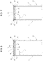
Figure 7 is a figure analogous toFigure 6 and illustrates a variant of a detail ofFigure 5 . - In
Figures 1 and 2 , reference numeral 1 indicates, as a whole, a luminescent body. - Here and in the following, the term "luminescent body" means a body having any shape, geometry and outer profile and intended to carry out any function such as, for example, a function of a sign, of an indication or displaying of information, of illumination, etc.
- With reference to
Figure 2 and, in particular, toFigure 3 , the body 1 comprises acasing 1A, which in turn comprises a front orfrontal wall 2, a rear orbottom wall 3 and aperipheral wall 4. - The
peripheral wall 4 is a structural wall, which surrounds thewalls peripheral portions said walls - The body 1 further comprises a
light source 6, for example an LED, arranged inside thecasing 1A. Preferably, thelight source 6 is connected to or carried by therear wall 3. Alternatively, the light source is carried by theside wall 4. In the described example, thewalls peripheral portions peripheral surfaces - In the described example, the
front wall 2 is a wall completely permeable to light. According to a variant not illustrated, thewall 2 is only partially permeable to light so as to define, in use, a set of lights and shadows or shades of colours. - Conveniently, the
front wall 2 is made of an opaline material. - Conveniently, moreover, both
walls wall 3 is an opaque wall made, for example, of PVC foam or other materials permeable to light. According to a variant not illustrated, at least one of the walls comprises at least one concave or convex portion and/or bulges or recesses or supports an engraved or printed or silk-screen printed text and/or an image or a figure. - According to a preferred embodiment, one or both
walls - According to a variant not illustrated, both
walls - In the described example, the
walls - In the described example, moreover, both
walls peripheral surfaces concave portions 7 joined to each other to form a plurality of cusps 8 (Figure 2 ). - According to a variant not illustrated, at least part of the
concave portions 7 are replaced by convex portions and, in general, by portions with concavities different from those indicated by way of example and/or different from each other. - According to a further variant not illustrated, at least part of the
concave portions 7 are replaced by flat portions. - Regardless of the shape of the
peripheral surfaces side wall 4 straddles thewalls annular reinforcement portion 10 and an outer annular coating andfinishing portion 11. - The
annular portion 10 extends between theportions shaped surface 13 which forms the extension of the outerperipheral surfaces Figure 3 . - Conveniently, the
annular portion 10 is made of extruded EPS or of polystyrene foam cut by hot wire or by milling or by laser along the outer peripheral edges of thewalls wall 4 from the outside, for example, by the fingers of a person's hands during the handling of the body 1 and directed towards the inside of thecasing 1A. - Preferably, the
annular portion 10 is firmly connected to thewalls - Conveniently, the
walls portion 10 by the interposition of a double-sided adhesive tape 15 (Figure 3 ). - Still with reference to
Figure 3 , thecoating portion 11 is C-shaped and comprises anintermediate portion 11A and twoside portions 11B turned down over theperipheral portions - According to a variant not illustrated, the
coating portion 11 is devoid of theportions 11B and theportion 11 ends flush with thewalls said walls - The
coating portion 11 is firmly connected to thesurfaces reinforcement portion 10 by gluing or, conveniently, by the interposition of a double-sidedadhesive tape 16. Theportions 11B, instead, are not glued to thewalls said walls - According to a variant, the
surfaces portion 11 either. - In the variant illustrated in
Figure 4 , theouter surface 13 of thereinforcement portion 10 is set back with respect to thesurfaces coating portion 11 is provided withcircumferential grooves 18 engaged by theperipheral portions coating portion 11 is glued to thesurfaces reinforcement portion 10 by the interposition of double-sidedadhesive tapes 16 or glue. According to a variant not illustrated, thereinforcement portion 10 may lack. In such case, the part of thecoating portion 11 arranged between theportions - According to a further variant, the
coating portion 11 comprises asingle groove 18, for example the one engaged by theportion 2A. In such case, theportion 3B is arranged in abutment against theportion 11, to which it is glued with glue or by double-sided adhesive tape. Still in such case, theportion 11B relative to thewall 3 may lack and thecoating portion 11 ends flush withsaid wall 3 or slightly protrudes cantilevered beyond the outer surface of thewall 3. - In the variant illustrated in
Figures 5 and6 , thereinforcement portion 10 is replaced by acorrugated portion 20, this too stabilising, connected to thecoating portion 11 by gluing or double-sided adhesive tapes as indicated in the foregoing. - Preferably, the
corrugated portion 20 is defined by a ribbed strip of paper-based material or other material that can be manually and plastically moulded, for example comprising aluminium or plastic materials and, in general, a material that allows faithfully following and maintaining the curvature of the outer peripheral edges of theplates casing 1A so as to make peripheral walls having restrained and at most null deflections. - Still in the described example, the
corrugated portion 20 has an ordered and periodic succession ofrectilinear projections 21 protruding towards the inside of thecasing 1A and delimiting between each other a plurality ofrectilinear grooves 22 or cavities which extend orthogonally to thewalls casing 1A (Figure 5 ). In this manner, theprojections 21 are connected to each other by weakened portions which facilitate the rotation or the displacement of theprojections 21 with respect to each other in the concave 7 or convex sections, if present, and at thecusps 8. The substantially plastic deformation of such weakened portions further allows counteracting any residual elastic tensions of the coating and finishingportion 11. - Conveniently, the
projections 21 taper towards the inside of thecasing 1A and thegrooves 22 are flared still towards the inside of saidcasing 1A. - Regardless of how the
corrugated portion 20 is manufactured, it is firmly connected to thecoating portion 11 by gluing or other equivalent mode of firm connection. Preferably, theportions adhesive tapes 16. - In the variant illustrated in
Figure 7 , thecoating portion 11 and thereinforcement portion 20, regardless of their shape or how they are manufactured, form part of abody 25 made in a single piece and with the same material with which thecoating portion 11 is made. Preferably, also in this solution, the reinforcement portion has theprojections 21 and thegrooves 22. - Regardless of its geometry, the
coating portion 11 is made of elastomeric foam material. Preferably, theportion 11 is made of closed-cell polymeric foam material. - Conveniently, the
coating portion 11 is made with a material selected from the group consisting of ethylenevinyl acetate (EVA), Ethylene-Propylene Diene Monomer (EPDM), chloroprene, styrene butadiene rubber (SBR), natural rubber, nitrile-butadiene rubber (NBR), ethylene vinyl monomer (EVM) and mixtures thereof. - According to a preferred embodiment, the
coating portion 11 is made of EPDM or of EVAFOAM. - Alternatively, the
coating portion 11 is made of a material sold under the name SE32CE by the company SOGIMI. - The materials listed above are elastically deformable materials, they all have high conformability or malleability and high stability or shape memory. This allows manufacturing bodies having high aesthetic quality with continuous and homogeneous peripheral profiles, i.e. devoid of discontinuities, such as bulges or wrinkles even and especially in the presence of significant variations in curvature.
- In other words, the aforementioned coating materials alone allow manufacturing peripheral walls and, therefore, structured luminescent bodies of high shape stability and high aesthetic quality, whatever the outer peripheral profile of the
plates - The aesthetic quality is further enhanced by the particular C shape of the coating portion and in any case by the fact that the turned-down
side portions 11B of saidcoating portion 11 are arranged in abutment against the outer surfaces of theperipheral portions Figures 3, 4 ,6 and 7 . Such turned-down portions define a finishing shutter, which, due to the chemical-physical characteristics of the material of theportion 11, is devoid of discontinuities and, when superimposed on thewalls side walls peripheral wall 4. - Moreover, the turned-down
side portions 11B, by effect of the elasticity of the material, exert, once assembly has been completed, a pressure over the entire periphery of therelative wall side walls walls walls - In addition, the elasticity of the
entire coating portion 11 makes the replacement of the foils even easier and faster should also thesurfaces portion 11. In any case, the elasticity of thecoating portion 11 allows using foils of different thickness. - The shape stability of the
peripheral wall 4 is further increased by thereinforcement portions corrugated portion 20, which, in addition to stiffening theside wall 4 and counteracting the inevitable elastic returns of thecoating portion 11, also carries out a function of guiding the strip during the winding around thewalls flat side walls side walls - It is evident in light of the foregoing that the described manufacturing methods allow manufacturing luminescent bodies of any shape and/or geometry and thus able to satisfy any request, need or customisation, in an extremely simple manner, in particularly short periods of time and at a particularly reasonable price.
- At the same time, the manufacturing method of the
peripheral wall 4 and the materials envisaged for its manufacture allows making bodies with a high degree of finishing and an unquestionable aesthetic quality that remains unaltered during the use of the luminescent body. - Said used materials, whatever their initial colouring, can in any case be easily painted in a light colour, preferably white, so that the chamber that houses the
light source 6 is delimited by a light-coloured surface which makes uniform and increases the light emission of the body 1. - It is evident from the foregoing that modifications and variants can be made to the described luminescent body 1 without thereby departing from the scope of protection defined by the independent claim. In particular, the geometries or the dimensional ratios may be different, as well as the methods for connecting to each other the various parts that make up the luminescent body 1.
Claims (11)
- A luminescent body (1) comprising a casing (1A) and a light source (6) housed in said casing; the casing (1A) comprising a front wall (2), a rear wall (3), a peripheral wall (4) surrounding the front (2) and rear (3) walls and firmly connected to the front and rear walls; at least one (2) of said front and rear walls comprising at least one portion permeable to light, characterised in that said peripheral wall (4) comprises an outer coating portion (11) and in that it comprises fixing means (15,16) for fixing said outer coating portion (11) to said front (2) and rear (3) walls; said outer coating portion (11) being made of elastomeric foam material.
- The body according to claim 1, characterised in that said outer coating portion (11) is made of closed-cell polymeric foam material.
- The body according to claim 1 or 2, characterised in that said outer coating portion is made with a material that is selected from the group consisting of ethylenevinyl acetate (EVA), Ethylene-Propylene Diene Monomer (EPDM), chloroprene, styrene butadiene rubber (SBR), natural rubber, nitrile-butadiene rubber (NBR), ethylene vinyl monomer (EVM) and mixtures thereof.
- The body according to claim 3, characterised in that said outer coating portion (11) is made of EPDM, or EVA foam or EVAFOAM.
- The body according to any one of the preceding claims, characterised in that said connection means comprise glues or adhesive materials (15)(16).
- The body according to any one of the preceding claims, characterised in that said peripheral wall (4) comprises a reinforcement portion (10); (20) of said outer coating portion (11); said reinforcement portion extending between said front and rear walls and being firmly connected to said front and rear walls and to said outer coating portion (11).
- The body according to claim 6, characterised in that said front (2) and rear (3) walls are delimited by respective outer peripheral surfaces (2B)(3B) and in that said reinforcement portion is delimited by a further outer peripheral surface (13) that forms an extension of said peripheral surfaces (2B) (3B) or is moved backwards towards the inside of the casing (1A) with respect to the same peripheral surfaces; said outer coating portion being rested on said further surface and firmly connected to the same further outer peripheral surface (13).
- The body according to claim 6, characterised in that said reinforcement portion (20) is a corrugated portion having ridges (21) extending transversely to said front (2) and rear (3) walls and delimiting between one another a plurality of grooves (22) having concavities facing towards the inside of the casing (1A).
- The body according to claim 8, characterised in that said outer coating portion (11) and said reinforcement portion form part of a body made in a single piece and with the same material with which said coating portion (11) is made.
- The body according to claim 8 or 9, characterised in that said outer coating portion (11) comprises, for at least one of the said front (2) and rear (3) walls, a relative circumferential groove (18), and in that at least one of said front and rear walls has a relative outer peripheral portion (3A)(3B) engaging said circumferential groove (18).
- The body according to any one of the preceding claims, characterised in that said outer coating portion (11) comprises a central portion (11A) and two side portions (11B) turned over on the outer surfaces of the front and rear side walls; said side portions (11B) being elastically forced against said outer surfaces.
Applications Claiming Priority (1)
| Application Number | Priority Date | Filing Date | Title |
|---|---|---|---|
| IT102020000027537A IT202000027537A1 (en) | 2020-11-17 | 2020-11-17 | LIGHT BODY |
Publications (3)
| Publication Number | Publication Date |
|---|---|
| EP4001746A1 true EP4001746A1 (en) | 2022-05-25 |
| EP4001746C0 EP4001746C0 (en) | 2025-01-01 |
| EP4001746B1 EP4001746B1 (en) | 2025-01-01 |
Family
ID=74557046
Family Applications (1)
| Application Number | Title | Priority Date | Filing Date |
|---|---|---|---|
| EP21208857.9A Active EP4001746B1 (en) | 2020-11-17 | 2021-11-17 | Luminescent body |
Country Status (2)
| Country | Link |
|---|---|
| EP (1) | EP4001746B1 (en) |
| IT (1) | IT202000027537A1 (en) |
Citations (6)
| Publication number | Priority date | Publication date | Assignee | Title |
|---|---|---|---|---|
| DE202006005991U1 (en) * | 2006-04-12 | 2006-10-12 | Zumtobel Lighting Gmbh | Electrical lighting element for surface mounting has a cover that is flexible in one direction for ease of use |
| EP2347773A1 (en) * | 2006-03-14 | 2011-07-27 | The Procter & Gamble Company | Decorative luminary |
| WO2014170075A1 (en) * | 2013-04-17 | 2014-10-23 | Osram Gmbh | A lighting device and a cleaning control method of the lighting device |
| KR101721027B1 (en) * | 2016-07-22 | 2017-04-18 | 주식회사 에스필코리아 | Visible Light-responsive Photocatalyst and Lighting Device Using the Same |
| US20180245754A1 (en) * | 2017-02-27 | 2018-08-30 | Elemental LED, Inc. | Linear LED Lighting with Built-In Light Modifiers |
| KR101971706B1 (en) * | 2018-10-31 | 2019-04-24 | 에스에스씨라이팅 주식회사 | Lighting apparatus having deodorization function |
Family Cites Families (1)
| Publication number | Priority date | Publication date | Assignee | Title |
|---|---|---|---|---|
| KR200448289Y1 (en) * | 2008-02-22 | 2010-03-29 | 김경남 | LED lighting device of advertising panel |
-
2020
- 2020-11-17 IT IT102020000027537A patent/IT202000027537A1/en unknown
-
2021
- 2021-11-17 EP EP21208857.9A patent/EP4001746B1/en active Active
Patent Citations (6)
| Publication number | Priority date | Publication date | Assignee | Title |
|---|---|---|---|---|
| EP2347773A1 (en) * | 2006-03-14 | 2011-07-27 | The Procter & Gamble Company | Decorative luminary |
| DE202006005991U1 (en) * | 2006-04-12 | 2006-10-12 | Zumtobel Lighting Gmbh | Electrical lighting element for surface mounting has a cover that is flexible in one direction for ease of use |
| WO2014170075A1 (en) * | 2013-04-17 | 2014-10-23 | Osram Gmbh | A lighting device and a cleaning control method of the lighting device |
| KR101721027B1 (en) * | 2016-07-22 | 2017-04-18 | 주식회사 에스필코리아 | Visible Light-responsive Photocatalyst and Lighting Device Using the Same |
| US20180245754A1 (en) * | 2017-02-27 | 2018-08-30 | Elemental LED, Inc. | Linear LED Lighting with Built-In Light Modifiers |
| KR101971706B1 (en) * | 2018-10-31 | 2019-04-24 | 에스에스씨라이팅 주식회사 | Lighting apparatus having deodorization function |
Also Published As
| Publication number | Publication date |
|---|---|
| EP4001746C0 (en) | 2025-01-01 |
| IT202000027537A1 (en) | 2022-05-17 |
| EP4001746B1 (en) | 2025-01-01 |
Similar Documents
| Publication | Publication Date | Title |
|---|---|---|
| BR112012005385B1 (en) | method for producing a component and component | |
| DE60213498D1 (en) | Composite sheet for a tire vulcanizing mold | |
| BR9908854B1 (en) | Method for the manufacture of tire combined with sealant. | |
| EP4001746B1 (en) | Luminescent body | |
| GB1440885A (en) | Auto trim | |
| US20060000176A1 (en) | Dual-durometer divided bar | |
| US6928762B1 (en) | Framing system | |
| US3284889A (en) | Method of making signs | |
| GB2031478A (en) | Covings and other decorative mouldings | |
| JP2008195132A (en) | Tire label and pneumatic tire | |
| JPS6011613B2 (en) | Manufacturing method of composite molded panels for lighting etc. | |
| CN103318104A (en) | Car roof decorative strip and installing structure thereof | |
| WO2017196747A1 (en) | Ray design and manufacturing methods | |
| CN115467462A (en) | A kind of suspended ceiling structure and construction method that can be embedded in lighting decoration | |
| WO2009124744A3 (en) | Method for producing a décor profile to which at least one functional element is attached | |
| KR200202569Y1 (en) | panel using for signboard, display, pop, planning of interior | |
| KR20230056403A (en) | Temba louver for exterior materials in buildings | |
| CN216671121U (en) | Light-emitting device based on acrylic plate | |
| CN220451211U (en) | Three-dimensional annular modeling aluminum plate ceiling | |
| CN222933702U (en) | Triangular window glass assembly and vehicle | |
| KR200276994Y1 (en) | ABS resin edge molding strip for furniture panel | |
| JP2016098525A (en) | Corner material for construction | |
| JP2019085789A (en) | Spandrel material | |
| JP2009052277A (en) | Handrail bracket | |
| JPH0381795A (en) | Reflecting sheet |
Legal Events
| Date | Code | Title | Description |
|---|---|---|---|
| PUAI | Public reference made under article 153(3) epc to a published international application that has entered the european phase |
Free format text: ORIGINAL CODE: 0009012 |
|
| STAA | Information on the status of an ep patent application or granted ep patent |
Free format text: STATUS: THE APPLICATION HAS BEEN PUBLISHED |
|
| AK | Designated contracting states |
Kind code of ref document: A1 Designated state(s): AL AT BE BG CH CY CZ DE DK EE ES FI FR GB GR HR HU IE IS IT LI LT LU LV MC MK MT NL NO PL PT RO RS SE SI SK SM TR |
|
| STAA | Information on the status of an ep patent application or granted ep patent |
Free format text: STATUS: REQUEST FOR EXAMINATION WAS MADE |
|
| 17P | Request for examination filed |
Effective date: 20221124 |
|
| RBV | Designated contracting states (corrected) |
Designated state(s): AL AT BE BG CH CY CZ DE DK EE ES FI FR GB GR HR HU IE IS IT LI LT LU LV MC MK MT NL NO PL PT RO RS SE SI SK SM TR |
|
| GRAP | Despatch of communication of intention to grant a patent |
Free format text: ORIGINAL CODE: EPIDOSNIGR1 |
|
| STAA | Information on the status of an ep patent application or granted ep patent |
Free format text: STATUS: GRANT OF PATENT IS INTENDED |
|
| INTG | Intention to grant announced |
Effective date: 20240208 |
|
| GRAJ | Information related to disapproval of communication of intention to grant by the applicant or resumption of examination proceedings by the epo deleted |
Free format text: ORIGINAL CODE: EPIDOSDIGR1 |
|
| STAA | Information on the status of an ep patent application or granted ep patent |
Free format text: STATUS: REQUEST FOR EXAMINATION WAS MADE |
|
| GRAP | Despatch of communication of intention to grant a patent |
Free format text: ORIGINAL CODE: EPIDOSNIGR1 |
|
| STAA | Information on the status of an ep patent application or granted ep patent |
Free format text: STATUS: GRANT OF PATENT IS INTENDED |
|
| INTC | Intention to grant announced (deleted) | ||
| INTG | Intention to grant announced |
Effective date: 20240705 |
|
| GRAS | Grant fee paid |
Free format text: ORIGINAL CODE: EPIDOSNIGR3 |
|
| GRAA | (expected) grant |
Free format text: ORIGINAL CODE: 0009210 |
|
| STAA | Information on the status of an ep patent application or granted ep patent |
Free format text: STATUS: THE PATENT HAS BEEN GRANTED |
|
| AK | Designated contracting states |
Kind code of ref document: B1 Designated state(s): AL AT BE BG CH CY CZ DE DK EE ES FI FR GB GR HR HU IE IS IT LI LT LU LV MC MK MT NL NO PL PT RO RS SE SI SK SM TR |
|
| REG | Reference to a national code |
Ref country code: GB Ref legal event code: FG4D |
|
| REG | Reference to a national code |
Ref country code: CH Ref legal event code: EP |
|
| REG | Reference to a national code |
Ref country code: DE Ref legal event code: R096 Ref document number: 602021024183 Country of ref document: DE |
|
| REG | Reference to a national code |
Ref country code: IE Ref legal event code: FG4D |
|
| U01 | Request for unitary effect filed |
Effective date: 20250113 |
|
| U07 | Unitary effect registered |
Designated state(s): AT BE BG DE DK EE FI FR IT LT LU LV MT NL PT RO SE SI Effective date: 20250120 |
|
| PG25 | Lapsed in a contracting state [announced via postgrant information from national office to epo] |
Ref country code: PL Free format text: LAPSE BECAUSE OF FAILURE TO SUBMIT A TRANSLATION OF THE DESCRIPTION OR TO PAY THE FEE WITHIN THE PRESCRIBED TIME-LIMIT Effective date: 20250101 |
|
| PG25 | Lapsed in a contracting state [announced via postgrant information from national office to epo] |
Ref country code: ES Free format text: LAPSE BECAUSE OF FAILURE TO SUBMIT A TRANSLATION OF THE DESCRIPTION OR TO PAY THE FEE WITHIN THE PRESCRIBED TIME-LIMIT Effective date: 20250101 |
|
| PG25 | Lapsed in a contracting state [announced via postgrant information from national office to epo] |
Ref country code: IS Free format text: LAPSE BECAUSE OF FAILURE TO SUBMIT A TRANSLATION OF THE DESCRIPTION OR TO PAY THE FEE WITHIN THE PRESCRIBED TIME-LIMIT Effective date: 20250501 Ref country code: NO Free format text: LAPSE BECAUSE OF FAILURE TO SUBMIT A TRANSLATION OF THE DESCRIPTION OR TO PAY THE FEE WITHIN THE PRESCRIBED TIME-LIMIT Effective date: 20250401 |
|
| PG25 | Lapsed in a contracting state [announced via postgrant information from national office to epo] |
Ref country code: HR Free format text: LAPSE BECAUSE OF FAILURE TO SUBMIT A TRANSLATION OF THE DESCRIPTION OR TO PAY THE FEE WITHIN THE PRESCRIBED TIME-LIMIT Effective date: 20250101 |
|
| PG25 | Lapsed in a contracting state [announced via postgrant information from national office to epo] |
Ref country code: GR Free format text: LAPSE BECAUSE OF FAILURE TO SUBMIT A TRANSLATION OF THE DESCRIPTION OR TO PAY THE FEE WITHIN THE PRESCRIBED TIME-LIMIT Effective date: 20250402 |
|
| PG25 | Lapsed in a contracting state [announced via postgrant information from national office to epo] |
Ref country code: CZ Free format text: LAPSE BECAUSE OF FAILURE TO SUBMIT A TRANSLATION OF THE DESCRIPTION OR TO PAY THE FEE WITHIN THE PRESCRIBED TIME-LIMIT Effective date: 20250101 |
|
| PG25 | Lapsed in a contracting state [announced via postgrant information from national office to epo] |
Ref country code: SM Free format text: LAPSE BECAUSE OF FAILURE TO SUBMIT A TRANSLATION OF THE DESCRIPTION OR TO PAY THE FEE WITHIN THE PRESCRIBED TIME-LIMIT Effective date: 20250101 |
|
| PG25 | Lapsed in a contracting state [announced via postgrant information from national office to epo] |
Ref country code: SK Free format text: LAPSE BECAUSE OF FAILURE TO SUBMIT A TRANSLATION OF THE DESCRIPTION OR TO PAY THE FEE WITHIN THE PRESCRIBED TIME-LIMIT Effective date: 20250101 |
|
| PLBE | No opposition filed within time limit |
Free format text: ORIGINAL CODE: 0009261 |
|
| STAA | Information on the status of an ep patent application or granted ep patent |
Free format text: STATUS: NO OPPOSITION FILED WITHIN TIME LIMIT |
|
| REG | Reference to a national code |
Ref country code: CH Ref legal event code: L10 Free format text: ST27 STATUS EVENT CODE: U-0-0-L10-L00 (AS PROVIDED BY THE NATIONAL OFFICE) Effective date: 20251112 |
|
| 26N | No opposition filed |
Effective date: 20251002 |
|
| U20 | Renewal fee for the european patent with unitary effect paid |
Year of fee payment: 5 Effective date: 20251113 |
|
| PGFP | Annual fee paid to national office [announced via postgrant information from national office to epo] |
Ref country code: GB Payment date: 20251127 Year of fee payment: 5 |
|
| REG | Reference to a national code |
Ref country code: CH Ref legal event code: H13 Free format text: ST27 STATUS EVENT CODE: U-0-0-H10-H13 (AS PROVIDED BY THE NATIONAL OFFICE) Effective date: 20260623 |
|
| PG25 | Lapsed in a contracting state [announced via postgrant information from national office to epo] |
Ref country code: MC Free format text: LAPSE BECAUSE OF FAILURE TO SUBMIT A TRANSLATION OF THE DESCRIPTION OR TO PAY THE FEE WITHIN THE PRESCRIBED TIME-LIMIT Effective date: 20250101 |
|
| PG25 | Lapsed in a contracting state [announced via postgrant information from national office to epo] |
Ref country code: RS Free format text: LAPSE BECAUSE OF FAILURE TO SUBMIT A TRANSLATION OF THE DESCRIPTION OR TO PAY THE FEE WITHIN THE PRESCRIBED TIME-LIMIT Effective date: 20250101 |
|
| PG25 | Lapsed in a contracting state [announced via postgrant information from national office to epo] |
Ref country code: CH Free format text: LAPSE BECAUSE OF NON-PAYMENT OF DUE FEES Effective date: 20251130 |