EP4001723A1 - Sealing device for connecting distribution ducts - Google Patents
Sealing device for connecting distribution ducts Download PDFInfo
- Publication number
- EP4001723A1 EP4001723A1 EP21383021.9A EP21383021A EP4001723A1 EP 4001723 A1 EP4001723 A1 EP 4001723A1 EP 21383021 A EP21383021 A EP 21383021A EP 4001723 A1 EP4001723 A1 EP 4001723A1
- Authority
- EP
- European Patent Office
- Prior art keywords
- seal
- sealing
- screws
- additional
- protruding members
- Prior art date
- Legal status (The legal status is an assumption and is not a legal conclusion. Google has not performed a legal analysis and makes no representation as to the accuracy of the status listed.)
- Granted
Links
Images
Classifications
-
- F—MECHANICAL ENGINEERING; LIGHTING; HEATING; WEAPONS; BLASTING
- F16—ENGINEERING ELEMENTS AND UNITS; GENERAL MEASURES FOR PRODUCING AND MAINTAINING EFFECTIVE FUNCTIONING OF MACHINES OR INSTALLATIONS; THERMAL INSULATION IN GENERAL
- F16L—PIPES; JOINTS OR FITTINGS FOR PIPES; SUPPORTS FOR PIPES, CABLES OR PROTECTIVE TUBING; MEANS FOR THERMAL INSULATION IN GENERAL
- F16L17/00—Joints with packing adapted to sealing by fluid pressure
- F16L17/02—Joints with packing adapted to sealing by fluid pressure with sealing rings arranged between outer surface of pipe and inner surface of sleeve or socket
- F16L17/04—Joints with packing adapted to sealing by fluid pressure with sealing rings arranged between outer surface of pipe and inner surface of sleeve or socket with longitudinally split or divided sleeve
Definitions
- the invention refers to a flexible seal for distribution ducts sealing junctions that contributes, to the function to which it is designed, with advantages and characteristics that will be disclosed in detail thereafter and that mean a novelty to the current state-of-art.
- the object of this invention refers to the sealing element of a sealing device of the type that, flange-like, is used to join by their ends two lengths of pipe of distribution duct of a fluid installation, normally water, which is essentially distinguished in that it comprises circumferential means compensation the "torque" that the pressure of the fluid can provoke on the screw joining the respective members of each end of the external body of the seal or flange that its closure possesses, providing an elastic sealing system that avoids an excessive and unrecoverable deformation of the closure and, consequently, favors an optimum operation of the seal or flange device.
- the field of application of this invention is within the sector of the industry engaged in the production of tubing or pipes sealing and fixation apparatuses and devices.
- flange-like or sealing elements are usually used that, basically, comprise an internal sealing gasket, formed by a circular band of soft material, an intermediate sealing body constituted by an open rim, that is fitted on the internal seal and is that is somewhat wider that this later, and an external seal body formed by another open rim, that is fixed, by screwing, on the intermediate body, avoiding that its opening coincides with its, and the ends of which possess a seal, that is the part of the junction that provides the assembly immobility and, consequently, the tightness between the lengths of the duct it encompasses, in which the existence of respective protruding members are provided, one at each end of the external body, which are provided with a series of through holes arranged so that they are facing each other, those of one member and the other member and between which, at least, a locking screw is inserted, and in addition it is foreseen to include a cross sealing axis of the locking screws at
- the objective of this invention is, therefore, to develop an improved type of seal for this type of sealing elements in which the described problem is avoided by including compensation means of the said eventual deviation to provide the recovery of the position of the sealing screw when the fluid pressure is no longer pushing the seal.
- the flexible seal for sealing distribution ducts that the invention proposes is configured as the suitable solution to the above-mentioned objective, the characterizing details making it possible and distinguishing it conveniently appearing in the final claims attached to this specification.
- a sealing element of the type integrated in a seal or flange element that serves to seal, by their ends two lengths of distribution duct of a fluid installation, normally water, where the pressure that the fluid can exert towards the walls of the pipes and consequently, towards the said device and, therefore, on the seal can provoke deformations in it is essentially distinguished in that it includes circumferential compensation means of the torque that the said pressure can provoke on the sealing screw or screws with which the respective members of each end of the external body of the seal or flange are fixed to each other that, conventionally, the said seal thereof comprises , providing an elastic seal system that, by compensation the said turn avoid an excessive or irrecoverable deformation of the seal and consequently, an eventual impairment of the functionality of the sealing device, favoring therefore an optimum operation thereof.
- the said circumferential compensation means are determined by the existence of one or more additional screws that, inserted between additional holes expressly pierced in an additional portion of the said members forming the seal in which the locking screw or screws are incorporated, compensate the deviation that these later can have as the said additional compensation screws are located above and externally to the sealing screws , that means, furthest from the center of the circumference that the different layers the sealing device comprises define.
- circumferential compensation means likewise comprise the incorporation in each of the protruding members an additional cross fixation axis that is inserted in elastic rings, providing the possibility of movement and recovery of the seal original position when it seems deformed.
- the flexible seal (1) of the invention forms an integral part of a seal device (2) designed to seal, by their ends, distribution duct pipes of a fluid installation, normally water, of the type that comprises, preferably, an internal seal (3), formed by a circular band of soft material, an intermediate sealing body (4) formed by an open rim , that is fitted on the internal junction (3) and that is somewhat wider that this later, and anyway, at least an external seal body (5) formed by another open rim that is fixed, by lateral screws (6) on the intermediate body (4) and the ends of which define the seal (1) that provides, in the position of use, the immobility of the assembly on the pipes to be sealed , which on its hand, in a well-known manner, comprises respective protruding members (7) joined jointly and respectively to each of the ends of the external body (5) of the device (2) , that are provided with one or several main through holes (8), arranged so that they are facing each those of the other member (7) and between which at least one sealing screw (9) and a
- the said flexible seal (1) of the invention is distinguished by the fact it comprises, in addition, circumferential compensation means (11) that compensate the seal (1) deformation that can be provoked by the eventual turn of the locking screw or screws (8) caused by the fluid pressure within the device (2).
- the said circumferential compensation means (11) are determined by the existence of one or more additional screws (111) that are incorporated inserted between one or more additional holes (112) pierced to that effect in an additional portion of the upper part of each of the two protruding members (7) of the seal (1), so that they remain located on the sealing screw or screws (9) and externally thereof, that means, furthest from the center of the circumference the different layers the joining device (2) comprises define.
- circumferential compensation means (11) comprise likewise, the incorporation in each of the protruding members (7) an additional cross fixation axis (113) inserted in elastic rings (114), providing the possibility of movement and recovery of the seal original position when it seems deformed.
Landscapes
- Engineering & Computer Science (AREA)
- General Engineering & Computer Science (AREA)
- Physics & Mathematics (AREA)
- Fluid Mechanics (AREA)
- Mechanical Engineering (AREA)
- Gasket Seals (AREA)
- Flanged Joints, Insulating Joints, And Other Joints (AREA)
Abstract
Description
- The invention, as stated in the title of this specification, refers to a flexible seal for distribution ducts sealing junctions that contributes, to the function to which it is designed, with advantages and characteristics that will be disclosed in detail thereafter and that mean a novelty to the current state-of-art.
- The object of this invention refers to the sealing element of a sealing device of the type that, flange-like, is used to join by their ends two lengths of pipe of distribution duct of a fluid installation, normally water, which is essentially distinguished in that it comprises circumferential means compensation the "torque" that the pressure of the fluid can provoke on the screw joining the respective members of each end of the external body of the seal or flange that its closure possesses, providing an elastic sealing system that avoids an excessive and unrecoverable deformation of the closure and, consequently, favors an optimum operation of the seal or flange device.
- The field of application of this invention is within the sector of the industry engaged in the production of tubing or pipes sealing and fixation apparatuses and devices.
- In the installations of fluid distribution ducts, for example water, formed by sealing lengths of ducts, flange-like or sealing elements are usually used that, basically, comprise an internal sealing gasket, formed by a circular band of soft material, an intermediate sealing body constituted by an open rim, that is fitted on the internal seal and is that is somewhat wider that this later, and an external seal body formed by another open rim, that is fixed, by screwing, on the intermediate body, avoiding that its opening coincides with its, and the ends of which possess a seal, that is the part of the junction that provides the assembly immobility and, consequently, the tightness between the lengths of the duct it encompasses, in which the existence of respective protruding members are provided, one at each end of the external body, which are provided with a series of through holes arranged so that they are facing each other, those of one member and the other member and between which, at least, a locking screw is inserted, and in addition it is foreseen to include a cross sealing axis of the locking screws at each of the two members.
- The problem with this type of seal, is that it can be submitted to a great pressure of the internal fluid, which provokes the seal outwards push, and the fact is that, eventually, because of the said pressure, a given "torque" or turn of the sealing screw or screws can occur due to a given deviation of the position between one and the other member of the external body of the sealing element in which the said screw or screws are tightened, which, in turn, can produce a defect in the seal occurs and, consequently , an eventual loss of tightness.
- The objective of this invention is, therefore, to develop an improved type of seal for this type of sealing elements in which the described problem is avoided by including compensation means of the said eventual deviation to provide the recovery of the position of the sealing screw when the fluid pressure is no longer pushing the seal.
- On the other hand, and as reference to the current state-of-the-art, it shall be pointed out that, at least this applicant is not aware of the existence of any other flexible seal for distribution ducts seals, nor of any other invention having a similar application, that possesses technical and structural characteristics equal or similar to those appearing in what is claimed herein.
- The flexible seal for sealing distribution ducts that the invention proposes is configured as the suitable solution to the above-mentioned objective, the characterizing details making it possible and distinguishing it conveniently appearing in the final claims attached to this specification.
- Concretely, what the invention proposes, as it was said before, is a sealing element of the type integrated in a seal or flange element that serves to seal, by their ends two lengths of distribution duct of a fluid installation, normally water, where the pressure that the fluid can exert towards the walls of the pipes and consequently, towards the said device and, therefore, on the seal can provoke deformations in it, is essentially distinguished in that it includes circumferential compensation means of the torque that the said pressure can provoke on the sealing screw or screws with which the respective members of each end of the external body of the seal or flange are fixed to each other that, conventionally, the said seal thereof comprises , providing an elastic seal system that, by compensation the said turn avoid an excessive or irrecoverable deformation of the seal and consequently, an eventual impairment of the functionality of the sealing device, favoring therefore an optimum operation thereof.
- For this and more concretely, the said circumferential compensation means are determined by the existence of one or more additional screws that, inserted between additional holes expressly pierced in an additional portion of the said members forming the seal in which the locking screw or screws are incorporated, compensate the deviation that these later can have as the said additional compensation screws are located above and externally to the sealing screws , that means, furthest from the center of the circumference that the different layers the sealing device comprises define.
- In addition, it is important to point out that the described circumferential compensation means likewise comprise the incorporation in each of the protruding members an additional cross fixation axis that is inserted in elastic rings, providing the possibility of movement and recovery of the seal original position when it seems deformed.
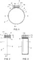
- To complement the description carried out and in order to assist to best understand the characteristics of the invention, attached to this specification, as an integral part thereof, a drawing in which for illustration and no limitation purpose, the following has been represented:
- The figures number 1.- It shows a schematic cross view, according to a cross section, marked as AA section in the
figure 2 , of an example of embodiment of a seal device or flange for distribution ducts that possesses the flexible seal object of the invention, the parts and elements it comprises can be seen as well as their configuration and arrangement; - The figure number 2.- It shows a schematic side elevation view of the seal device and its closure, according to the invention, appearing in the
figure 1 ; and - The
figure 3 .- It newly shows a schematic cross section of the seal device with elastic closure, according to the invention, appearing in the preceding figures, in this case according to the B-B longitudinal section appearing in thefigure 1 . - Seen the said figures and according to the numerals adopted, a no limiting example of embodiment can be seen of the flexible seal for sealing distribution ducts of the invention which comprises what is described in details below.
- Thus, as it can be seen in the said figures, the flexible seal (1) of the invention forms an integral part of a seal device (2) designed to seal, by their ends, distribution duct pipes of a fluid installation, normally water, of the type that comprises, preferably, an internal seal (3), formed by a circular band of soft material, an intermediate sealing body (4) formed by an open rim , that is fitted on the internal junction (3) and that is somewhat wider that this later, and anyway, at least an external seal body (5) formed by another open rim that is fixed, by lateral screws (6) on the intermediate body (4) and the ends of which define the seal (1) that provides, in the position of use, the immobility of the assembly on the pipes to be sealed , which on its hand, in a well-known manner, comprises respective protruding members (7) joined jointly and respectively to each of the ends of the external body (5) of the device (2) , that are provided with one or several main through holes (8), arranged so that they are facing each those of the other member (7) and between which at least one sealing screw (9) and a cross sealing axis (10) are inserted in each member.
- From this already known configuration, the said flexible seal (1) of the invention is distinguished by the fact it comprises, in addition, circumferential compensation means (11) that compensate the seal (1) deformation that can be provoked by the eventual turn of the locking screw or screws (8) caused by the fluid pressure within the device (2).
- Preferably, the said circumferential compensation means (11) are determined by the existence of one or more additional screws (111) that are incorporated inserted between one or more additional holes (112) pierced to that effect in an additional portion of the upper part of each of the two protruding members (7) of the seal (1), so that they remain located on the sealing screw or screws (9) and externally thereof, that means, furthest from the center of the circumference the different layers the joining device (2) comprises define.
- In addition, it is important to point out that the describe circumferential compensation means (11) comprise likewise, the incorporation in each of the protruding members (7) an additional cross fixation axis (113) inserted in elastic rings (114), providing the possibility of movement and recovery of the seal original position when it seems deformed.
- Sufficiently disclosed the nature of this invention, as well as the manner of implementing it, it is not deemed necessary to extend anymore its explanation in order that any man skilled in the art understands its scope and the advantages arising from it.
Claims (2)
- Flexible seal for sealing distribution ducts that, being of the type forming an integral part of a sealing device (2) designed to seal, by their ends, distribution duct pipes of a fluid installation, normally water, of the type that comprises, preferably, an external seal body (5) formed by an open rim the ends of which define the seal (1) that provides, in the position of use, the immobility of the assembly on the pipes to be sealed , the said seal (1) comprising respective protruding members (7) joined jointly and respectively to each of the ends of the external body (5) of the device (2) , that are provided with one or several main through holes (8), arranged so that they are facing each those of the other member (7) and between which at least one sealing screw (9) and a cross sealing axis (10) are inserted characterized in that in addition it comprises circumferential compensation means (11) determined by the existence of one or more additional screws (111) that are incorporated inserted between one or more additional holes (112) pierced to that effect in an additional portion of the upper part of each of the protruding members (7) of the seal (1), so that they remain located on the sealing screw or screws (9) and externally to the sealing screws , that means, furthest from the center of the circumference that the different layers the sealing device (2) comprises define.
- Flexible seal for sealing distribution ducts according to the claim 1, characterized in that the circumferential compensation means (11) comprise likewise, the incorporation in each of the protruding members (7) an additional cross fixation axis (113) inserted in elastic rings (114).
Applications Claiming Priority (1)
| Application Number | Priority Date | Filing Date | Title |
|---|---|---|---|
| ES202032438U ES1264236Y (en) | 2020-11-12 | 2020-11-12 | FLEXIBLE JOINT CLOSURE FOR TIGHTENING JOINTS OF CHANNELS |
Publications (3)
| Publication Number | Publication Date |
|---|---|
| EP4001723A1 true EP4001723A1 (en) | 2022-05-25 |
| EP4001723C0 EP4001723C0 (en) | 2025-01-08 |
| EP4001723B1 EP4001723B1 (en) | 2025-01-08 |
Family
ID=75222378
Family Applications (1)
| Application Number | Title | Priority Date | Filing Date |
|---|---|---|---|
| EP21383021.9A Active EP4001723B1 (en) | 2020-11-12 | 2021-11-11 | Sealing coupling for connecting distribution ducts |
Country Status (2)
| Country | Link |
|---|---|
| EP (1) | EP4001723B1 (en) |
| ES (2) | ES1264236Y (en) |
Citations (3)
| Publication number | Priority date | Publication date | Assignee | Title |
|---|---|---|---|---|
| FR1028176A (en) * | 1950-11-06 | 1953-05-20 | Removable connecting sleeve | |
| US4108479A (en) * | 1976-07-21 | 1978-08-22 | Immanuel Straub | Pipe coupling |
| GB2389395A (en) * | 2002-06-07 | 2003-12-10 | Taylor Kerr | Pipe coupling with reinforced flange members |
-
2020
- 2020-11-12 ES ES202032438U patent/ES1264236Y/en active Active
-
2021
- 2021-11-11 EP EP21383021.9A patent/EP4001723B1/en active Active
- 2021-11-11 ES ES21383021T patent/ES3014164T3/en active Active
Patent Citations (3)
| Publication number | Priority date | Publication date | Assignee | Title |
|---|---|---|---|---|
| FR1028176A (en) * | 1950-11-06 | 1953-05-20 | Removable connecting sleeve | |
| US4108479A (en) * | 1976-07-21 | 1978-08-22 | Immanuel Straub | Pipe coupling |
| GB2389395A (en) * | 2002-06-07 | 2003-12-10 | Taylor Kerr | Pipe coupling with reinforced flange members |
Also Published As
| Publication number | Publication date |
|---|---|
| ES3014164T3 (en) | 2025-04-21 |
| EP4001723C0 (en) | 2025-01-08 |
| ES1264236U (en) | 2021-03-31 |
| EP4001723B1 (en) | 2025-01-08 |
| ES1264236Y (en) | 2021-06-21 |
Similar Documents
| Publication | Publication Date | Title |
|---|---|---|
| US4832380A (en) | Pipe connection and clamp for same | |
| US9903517B2 (en) | Flange coupling part reinforcing jig | |
| US4518177A (en) | Hubless pipe coupling | |
| US2635900A (en) | Pressure-tight tube joint | |
| US20080157523A1 (en) | Detachable pipe joint | |
| US1926107A (en) | Sealing device | |
| WO2014176299A1 (en) | Coupling for range of pipe diameters | |
| US3836182A (en) | Pipe coupling system for glass or ceramic pipes and related materials | |
| EP3735549B1 (en) | Pipe coupling capsulation assembly with retaining elements | |
| US2887328A (en) | Pressure-sealing coupling for plain end pipe | |
| JP2016532080A (en) | Pressure transmitter seals used in industrial processes | |
| JP6962729B2 (en) | Leakage prevention device | |
| EP4001723A1 (en) | Sealing device for connecting distribution ducts | |
| KR200477445Y1 (en) | An end packing for pipe | |
| JP5665801B2 (en) | Pressers and fittings and valves | |
| JP2019138385A (en) | Flange-type pipe joint for small-diameter pipe | |
| KR101449428B1 (en) | Coupling of pipe | |
| EP3277990A1 (en) | Mechanical seal assembly | |
| US20180266614A1 (en) | Pipe coupling encapsulation assembly | |
| CA3073903C (en) | Pipe coupling with protection against fastener shearing | |
| JP6490451B2 (en) | Leakage prevention device for flange joints | |
| EP3724516A1 (en) | Connecting ring with an axial limiting feature | |
| US4795134A (en) | Valve with improved sealing properties | |
| EP4361489A1 (en) | Pipe coupling encapsulation assembly | |
| CN210600664U (en) | Urgent repair device for reducing pipe joint |
Legal Events
| Date | Code | Title | Description |
|---|---|---|---|
| PUAI | Public reference made under article 153(3) epc to a published international application that has entered the european phase |
Free format text: ORIGINAL CODE: 0009012 |
|
| STAA | Information on the status of an ep patent application or granted ep patent |
Free format text: STATUS: THE APPLICATION HAS BEEN PUBLISHED |
|
| AK | Designated contracting states |
Kind code of ref document: A1 Designated state(s): AL AT BE BG CH CY CZ DE DK EE ES FI FR GB GR HR HU IE IS IT LI LT LU LV MC MK MT NL NO PL PT RO RS SE SI SK SM TR |
|
| STAA | Information on the status of an ep patent application or granted ep patent |
Free format text: STATUS: REQUEST FOR EXAMINATION WAS MADE |
|
| 17P | Request for examination filed |
Effective date: 20221122 |
|
| STAA | Information on the status of an ep patent application or granted ep patent |
Free format text: STATUS: EXAMINATION IS IN PROGRESS |
|
| 17Q | First examination report despatched |
Effective date: 20240216 |
|
| GRAP | Despatch of communication of intention to grant a patent |
Free format text: ORIGINAL CODE: EPIDOSNIGR1 |
|
| STAA | Information on the status of an ep patent application or granted ep patent |
Free format text: STATUS: GRANT OF PATENT IS INTENDED |
|
| INTG | Intention to grant announced |
Effective date: 20240722 |
|
| GRAS | Grant fee paid |
Free format text: ORIGINAL CODE: EPIDOSNIGR3 |
|
| GRAA | (expected) grant |
Free format text: ORIGINAL CODE: 0009210 |
|
| STAA | Information on the status of an ep patent application or granted ep patent |
Free format text: STATUS: THE PATENT HAS BEEN GRANTED |
|
| AK | Designated contracting states |
Kind code of ref document: B1 Designated state(s): AL AT BE BG CH CY CZ DE DK EE ES FI FR GB GR HR HU IE IS IT LI LT LU LV MC MK MT NL NO PL PT RO RS SE SI SK SM TR |
|
| REG | Reference to a national code |
Ref country code: GB Ref legal event code: FG4D |
|
| REG | Reference to a national code |
Ref country code: CH Ref legal event code: EP |
|
| REG | Reference to a national code |
Ref country code: DE Ref legal event code: R096 Ref document number: 602021024632 Country of ref document: DE |
|
| REG | Reference to a national code |
Ref country code: IE Ref legal event code: FG4D |
|
| U01 | Request for unitary effect filed |
Effective date: 20250124 |
|
| U07 | Unitary effect registered |
Designated state(s): AT BE BG DE DK EE FI FR IT LT LU LV MT NL PT RO SE SI Effective date: 20250131 |
|
| REG | Reference to a national code |
Ref country code: ES Ref legal event code: FG2A Ref document number: 3014164 Country of ref document: ES Kind code of ref document: T3 Effective date: 20250421 |
|
| PG25 | Lapsed in a contracting state [announced via postgrant information from national office to epo] |
Ref country code: RS Free format text: LAPSE BECAUSE OF FAILURE TO SUBMIT A TRANSLATION OF THE DESCRIPTION OR TO PAY THE FEE WITHIN THE PRESCRIBED TIME-LIMIT Effective date: 20250408 |
|
| PG25 | Lapsed in a contracting state [announced via postgrant information from national office to epo] |
Ref country code: PL Free format text: LAPSE BECAUSE OF FAILURE TO SUBMIT A TRANSLATION OF THE DESCRIPTION OR TO PAY THE FEE WITHIN THE PRESCRIBED TIME-LIMIT Effective date: 20250108 |
|
| PG25 | Lapsed in a contracting state [announced via postgrant information from national office to epo] |
Ref country code: NO Free format text: LAPSE BECAUSE OF FAILURE TO SUBMIT A TRANSLATION OF THE DESCRIPTION OR TO PAY THE FEE WITHIN THE PRESCRIBED TIME-LIMIT Effective date: 20250408 Ref country code: IS Free format text: LAPSE BECAUSE OF FAILURE TO SUBMIT A TRANSLATION OF THE DESCRIPTION OR TO PAY THE FEE WITHIN THE PRESCRIBED TIME-LIMIT Effective date: 20250508 |
|
| PG25 | Lapsed in a contracting state [announced via postgrant information from national office to epo] |
Ref country code: HR Free format text: LAPSE BECAUSE OF FAILURE TO SUBMIT A TRANSLATION OF THE DESCRIPTION OR TO PAY THE FEE WITHIN THE PRESCRIBED TIME-LIMIT Effective date: 20250108 |
|
| PG25 | Lapsed in a contracting state [announced via postgrant information from national office to epo] |
Ref country code: GR Free format text: LAPSE BECAUSE OF FAILURE TO SUBMIT A TRANSLATION OF THE DESCRIPTION OR TO PAY THE FEE WITHIN THE PRESCRIBED TIME-LIMIT Effective date: 20250409 |
|
| PG25 | Lapsed in a contracting state [announced via postgrant information from national office to epo] |
Ref country code: SM Free format text: LAPSE BECAUSE OF FAILURE TO SUBMIT A TRANSLATION OF THE DESCRIPTION OR TO PAY THE FEE WITHIN THE PRESCRIBED TIME-LIMIT Effective date: 20250108 |
|
| PG25 | Lapsed in a contracting state [announced via postgrant information from national office to epo] |
Ref country code: CZ Free format text: LAPSE BECAUSE OF FAILURE TO SUBMIT A TRANSLATION OF THE DESCRIPTION OR TO PAY THE FEE WITHIN THE PRESCRIBED TIME-LIMIT Effective date: 20250108 |
|
| PG25 | Lapsed in a contracting state [announced via postgrant information from national office to epo] |
Ref country code: SK Free format text: LAPSE BECAUSE OF FAILURE TO SUBMIT A TRANSLATION OF THE DESCRIPTION OR TO PAY THE FEE WITHIN THE PRESCRIBED TIME-LIMIT Effective date: 20250108 |
|
| PLBE | No opposition filed within time limit |
Free format text: ORIGINAL CODE: 0009261 |
|
| STAA | Information on the status of an ep patent application or granted ep patent |
Free format text: STATUS: NO OPPOSITION FILED WITHIN TIME LIMIT |
|
| REG | Reference to a national code |
Ref country code: CH Ref legal event code: L10 Free format text: ST27 STATUS EVENT CODE: U-0-0-L10-L00 (AS PROVIDED BY THE NATIONAL OFFICE) Effective date: 20251119 |
|
| U20 | Renewal fee for the european patent with unitary effect paid |
Year of fee payment: 5 Effective date: 20251105 |
|
| 26N | No opposition filed |
Effective date: 20251009 |
|
| REG | Reference to a national code |
Ref country code: CH Ref legal event code: U11 Free format text: ST27 STATUS EVENT CODE: U-0-0-U10-U11 (AS PROVIDED BY THE NATIONAL OFFICE) Effective date: 20260108 |
|
| PGFP | Annual fee paid to national office [announced via postgrant information from national office to epo] |
Ref country code: GB Payment date: 20251126 Year of fee payment: 5 |
|
| PGFP | Annual fee paid to national office [announced via postgrant information from national office to epo] |
Ref country code: ES Payment date: 20251201 Year of fee payment: 5 |
|
| PGFP | Annual fee paid to national office [announced via postgrant information from national office to epo] |
Ref country code: CH Payment date: 20260108 Year of fee payment: 5 |