EP4001684A1 - Two-speed gearbox for an electric motor - Google Patents
Two-speed gearbox for an electric motor Download PDFInfo
- Publication number
- EP4001684A1 EP4001684A1 EP20208649.2A EP20208649A EP4001684A1 EP 4001684 A1 EP4001684 A1 EP 4001684A1 EP 20208649 A EP20208649 A EP 20208649A EP 4001684 A1 EP4001684 A1 EP 4001684A1
- Authority
- EP
- European Patent Office
- Prior art keywords
- shaft
- clutch
- gear assembly
- gear
- clutch members
- Prior art date
- Legal status (The legal status is an assumption and is not a legal conclusion. Google has not performed a legal analysis and makes no representation as to the accuracy of the status listed.)
- Granted
Links
Images

Classifications
-
- F—MECHANICAL ENGINEERING; LIGHTING; HEATING; WEAPONS; BLASTING
- F16—ENGINEERING ELEMENTS AND UNITS; GENERAL MEASURES FOR PRODUCING AND MAINTAINING EFFECTIVE FUNCTIONING OF MACHINES OR INSTALLATIONS; THERMAL INSULATION IN GENERAL
- F16D—COUPLINGS FOR TRANSMITTING ROTATION; CLUTCHES; BRAKES
- F16D25/00—Fluid-actuated clutches
- F16D25/06—Fluid-actuated clutches in which the fluid actuates a piston incorporated in, i.e. rotating with the clutch
- F16D25/062—Fluid-actuated clutches in which the fluid actuates a piston incorporated in, i.e. rotating with the clutch the clutch having friction surfaces
- F16D25/063—Fluid-actuated clutches in which the fluid actuates a piston incorporated in, i.e. rotating with the clutch the clutch having friction surfaces with clutch members exclusively moving axially
- F16D25/0635—Fluid-actuated clutches in which the fluid actuates a piston incorporated in, i.e. rotating with the clutch the clutch having friction surfaces with clutch members exclusively moving axially with flat friction surfaces, e.g. discs
- F16D25/0638—Fluid-actuated clutches in which the fluid actuates a piston incorporated in, i.e. rotating with the clutch the clutch having friction surfaces with clutch members exclusively moving axially with flat friction surfaces, e.g. discs with more than two discs, e.g. multiple lamellae
-
- F—MECHANICAL ENGINEERING; LIGHTING; HEATING; WEAPONS; BLASTING
- F16—ENGINEERING ELEMENTS AND UNITS; GENERAL MEASURES FOR PRODUCING AND MAINTAINING EFFECTIVE FUNCTIONING OF MACHINES OR INSTALLATIONS; THERMAL INSULATION IN GENERAL
- F16H—GEARING
- F16H3/00—Toothed gearings for conveying rotary motion with variable gear ratio or for reversing rotary motion
- F16H3/02—Toothed gearings for conveying rotary motion with variable gear ratio or for reversing rotary motion without gears having orbital motion
- F16H3/08—Toothed gearings for conveying rotary motion with variable gear ratio or for reversing rotary motion without gears having orbital motion exclusively or essentially with continuously meshing gears, that can be disengaged from their shafts
- F16H3/087—Toothed gearings for conveying rotary motion with variable gear ratio or for reversing rotary motion without gears having orbital motion exclusively or essentially with continuously meshing gears, that can be disengaged from their shafts characterised by the disposition of the gears
- F16H3/089—Toothed gearings for conveying rotary motion with variable gear ratio or for reversing rotary motion without gears having orbital motion exclusively or essentially with continuously meshing gears, that can be disengaged from their shafts characterised by the disposition of the gears all of the meshing gears being supported by a pair of parallel shafts, one being the input shaft and the other the output shaft, there being no countershaft involved
-
- F—MECHANICAL ENGINEERING; LIGHTING; HEATING; WEAPONS; BLASTING
- F16—ENGINEERING ELEMENTS AND UNITS; GENERAL MEASURES FOR PRODUCING AND MAINTAINING EFFECTIVE FUNCTIONING OF MACHINES OR INSTALLATIONS; THERMAL INSULATION IN GENERAL
- F16H—GEARING
- F16H3/00—Toothed gearings for conveying rotary motion with variable gear ratio or for reversing rotary motion
- F16H3/02—Toothed gearings for conveying rotary motion with variable gear ratio or for reversing rotary motion without gears having orbital motion
- F16H3/08—Toothed gearings for conveying rotary motion with variable gear ratio or for reversing rotary motion without gears having orbital motion exclusively or essentially with continuously meshing gears, that can be disengaged from their shafts
- F16H3/087—Toothed gearings for conveying rotary motion with variable gear ratio or for reversing rotary motion without gears having orbital motion exclusively or essentially with continuously meshing gears, that can be disengaged from their shafts characterised by the disposition of the gears
- F16H3/091—Toothed gearings for conveying rotary motion with variable gear ratio or for reversing rotary motion without gears having orbital motion exclusively or essentially with continuously meshing gears, that can be disengaged from their shafts characterised by the disposition of the gears including a single countershaft
-
- F—MECHANICAL ENGINEERING; LIGHTING; HEATING; WEAPONS; BLASTING
- F16—ENGINEERING ELEMENTS AND UNITS; GENERAL MEASURES FOR PRODUCING AND MAINTAINING EFFECTIVE FUNCTIONING OF MACHINES OR INSTALLATIONS; THERMAL INSULATION IN GENERAL
- F16D—COUPLINGS FOR TRANSMITTING ROTATION; CLUTCHES; BRAKES
- F16D21/00—Systems comprising a plurality of actuated clutches
- F16D21/02—Systems comprising a plurality of actuated clutches for interconnecting three or more shafts or other transmission members in different ways
- F16D21/04—Systems comprising a plurality of actuated clutches for interconnecting three or more shafts or other transmission members in different ways with a shaft carrying a number of rotatable transmission members, e.g. gears, each of which can be connected to the shaft by a clutching member or members between the shaft and the hub of the transmission member
-
- F—MECHANICAL ENGINEERING; LIGHTING; HEATING; WEAPONS; BLASTING
- F16—ENGINEERING ELEMENTS AND UNITS; GENERAL MEASURES FOR PRODUCING AND MAINTAINING EFFECTIVE FUNCTIONING OF MACHINES OR INSTALLATIONS; THERMAL INSULATION IN GENERAL
- F16H—GEARING
- F16H57/00—General details of gearing
- F16H57/02—Gearboxes; Mounting gearing therein
- F16H57/023—Mounting or installation of gears or shafts in the gearboxes, e.g. methods or means for assembly
-
- F—MECHANICAL ENGINEERING; LIGHTING; HEATING; WEAPONS; BLASTING
- F16—ENGINEERING ELEMENTS AND UNITS; GENERAL MEASURES FOR PRODUCING AND MAINTAINING EFFECTIVE FUNCTIONING OF MACHINES OR INSTALLATIONS; THERMAL INSULATION IN GENERAL
- F16H—GEARING
- F16H61/00—Control functions within control units of change-speed- or reversing-gearings for conveying rotary motion ; Control of exclusively fluid gearing, friction gearing, gearings with endless flexible members or other particular types of gearing
- F16H61/26—Generation or transmission of movements for final actuating mechanisms
- F16H61/28—Generation or transmission of movements for final actuating mechanisms with at least one movement of the final actuating mechanism being caused by a non-mechanical force, e.g. power-assisted
-
- F—MECHANICAL ENGINEERING; LIGHTING; HEATING; WEAPONS; BLASTING
- F16—ENGINEERING ELEMENTS AND UNITS; GENERAL MEASURES FOR PRODUCING AND MAINTAINING EFFECTIVE FUNCTIONING OF MACHINES OR INSTALLATIONS; THERMAL INSULATION IN GENERAL
- F16H—GEARING
- F16H57/00—General details of gearing
- F16H57/02—Gearboxes; Mounting gearing therein
- F16H2057/02034—Gearboxes combined or connected with electric machines
-
- F—MECHANICAL ENGINEERING; LIGHTING; HEATING; WEAPONS; BLASTING
- F16—ENGINEERING ELEMENTS AND UNITS; GENERAL MEASURES FOR PRODUCING AND MAINTAINING EFFECTIVE FUNCTIONING OF MACHINES OR INSTALLATIONS; THERMAL INSULATION IN GENERAL
- F16H—GEARING
- F16H2200/00—Transmissions for multiple ratios
- F16H2200/0021—Transmissions for multiple ratios specially adapted for electric vehicles
-
- F—MECHANICAL ENGINEERING; LIGHTING; HEATING; WEAPONS; BLASTING
- F16—ENGINEERING ELEMENTS AND UNITS; GENERAL MEASURES FOR PRODUCING AND MAINTAINING EFFECTIVE FUNCTIONING OF MACHINES OR INSTALLATIONS; THERMAL INSULATION IN GENERAL
- F16H—GEARING
- F16H2200/00—Transmissions for multiple ratios
- F16H2200/003—Transmissions for multiple ratios characterised by the number of forward speeds
- F16H2200/0034—Transmissions for multiple ratios characterised by the number of forward speeds the gear ratios comprising two forward speeds
-
- F—MECHANICAL ENGINEERING; LIGHTING; HEATING; WEAPONS; BLASTING
- F16—ENGINEERING ELEMENTS AND UNITS; GENERAL MEASURES FOR PRODUCING AND MAINTAINING EFFECTIVE FUNCTIONING OF MACHINES OR INSTALLATIONS; THERMAL INSULATION IN GENERAL
- F16H—GEARING
- F16H2200/00—Transmissions for multiple ratios
- F16H2200/20—Transmissions using gears with orbital motion
- F16H2200/203—Transmissions using gears with orbital motion characterised by the engaging friction means not of the freewheel type, e.g. friction clutches or brakes
- F16H2200/2035—Transmissions using gears with orbital motion characterised by the engaging friction means not of the freewheel type, e.g. friction clutches or brakes with two engaging means
Definitions
- the invention relates to a gear assembly for use with an electric motor, comprising a shaft with a gear both on a first end and on a second end, each gear connected to a respective clutch, the clutch comprising a first and a second clutch member, the gear assembly comprising a force member for axially moving the first clutch members relative to the second clutch members in an axial direction for slipping engaging and disengaging at relative circumferential speeds.
- the invention also relates to an interconnecting plate for use in a gear assembly and to an electric vehicle comprising such a gear assembly.
- the most suitable shifting strategy is the so-called power shift, i.e. shifting without torque interruption, which is especially important for premium vehicles.
- Power shift can be achieved using two wet clutches, one of which governs gear 1 and the other gear 2.
- gear 1 gear 1
- gear 2 gear 2
- a suitable place for both clutches is on an intermediate shaft (lay shaft) in a typically offset electric drive gearbox.
- An electric motor is known with a main shaft having at each end a gear that engages with a respective gear on a parallel lay shaft via two transmissions.
- the parallel shaft is coupled to the differential.
- Each gear on the intermediate shaft is provided with a respective transmission and clutch of the wet multiple disc type.
- a gear assembly for use with an electric motor comprising a shaft with a rotatable gear both on a first end and on a second end, each gear connected to a first clutch member fixedly connected to the gear, and the first clutch member being connectable to a second clutch member extending around the shaft and connected to the shaft in a fixed angular position, a force member being axially situated between the clutch members for axially moving the second clutch members relative to the first clutch members in an axial direction such that the first clutch members and the second clutch members can engage and disengage in a slipping manner at relative circumferential speeds.
- the shaft is supported by bearings at each end of the shaft near a respective gear.
- the close proximity of the gears to the bearings of the shaft results in reduced bending of the shaft. This provides better meshing contact of the gear teeth and results in reduced noise and wear.
- the second clutch members preferably extend around the shaft and are situated closer to a midpoint of the shaft than the gears.
- the clutch members do not create any radial forces on the shaft and act only in the axial direction. This allows the clutch members to be situated near the midpoint of the shaft, at a relatively large distance from the bearings.
- An embodiment of a gear assembly according to the invention comprises a controller connected to the force member and adapted for actuating the force member in such a manner that one of the second clutch members engages with its corresponding first clutch member while the other of the second clutch members disengages from its corresponding first clutch member such that a transfer of torque from the gears to the axle is substantially constant.
- the controller can comprise an oil pressure control circuit which governs clutch engagement and disengagement.
- Such controllers are known, for instance from dual clutch transmissions (DCTs) and conventional planetary gear automatic gearboxes.
- DCTs dual clutch transmissions
- the other clutch which is about to engage with the other gear is smoothly engaged by increasing of the oil pressure, until all the torque is passed from one gear to the other.
- torque is transferred with no or at most a very small, unnoticeable interruption during the shifting event.
- the force member may comprise for each second clutch member a hydraulic actuator that is operated by the control circuit.
- the gear assembly can be placed in a housing having a first and a second housing segment and an interconnecting plate situated at an interface between the housing segments, the interconnecting plate supporting the hydraulic actuators.
- the interconnecting plate comprising hydraulic actuating cylinders is clamped between the housing segments. It can be easily mounted and released for maintenance and repair of the cylinders. Hydraulic cylinders can be integrated in the interconnecting plate by directly machining the cylinders in the form of ring-shaped grooves in the cast blank. In addition, all the oil feed channels can also be integrated by drilling in the metal interconnecting plate.
- the interconnecting plate may be clamped between the motor housing and the gearbox housing so that a single set of connectors can be used to join all 3 structural parts. In that case for instance relatively long bolts can be used. This provides a more efficient way of connecting the plate compared to the use of separate dedicated bolts.
- Figure 1 shows an electric motor 1 comprising a driving shaft 2 that is mounted in bearings 4, 5.
- the driving shaft 2 has fixed thereon gears 6,7 of the first stage of the gearbox, which mesh with matching gears 8,9 of the first stage.
- the gears 8,9 can freely rotate about an intermediate, or lay shaft 15 and can via wet clutches 10,11 be engaged with the shaft 15, that is supported by bearings 16, 17.
- the intermediate shaft 15 drives gears 19 and 20 of a second or final stage, acting on an output shaft 18 which may for instance connect to a differential of the wheels.
- the rotational speed of the intermediate shaft 15 is between about 1.5 and 2.5 times lower than the rotational speed of the driving shaft 2.
- FIG. 1 shows the clutches 10, 11 on the intermediate shaft 15.
- the gears 8,9 are mounted on the shaft 15 via a clearance fit 22, 23, so that they can freely spin.
- the outer drums 24, 25 of each clutch 10, 11 are fixedly connected to the gears 8,9.
- the inner drums 26, 27 of the clutches 10, 11 are connected to the shaft 15 via splines in a fixed angular position.
- the inner drums 26, 27 comprise radial plates, or clutch discs 29, 30 that are adjacent and intermeshing with clutch discs 31, 32 of the outer drums 24,25.
- the rings 33, 34 are actuated by oil pressure in ducts 35, 36 that is generated by hydraulic actuators 37,38, that may for instance comprise hydraulic cylinders and pistons and that are controlled by controller 40.
- the rings 33, 34 form pistons that are accommodated in a respective annular groove 51, 52 of an interconnecting plate 46 of the housing of the gear box and are in fluid-tight contact with the walls of these annular grooves via circumferential seals 41, 42.
- the controller 40 operates the axial displacement of the rings 33, 34 such that a gradual decrease in oil pressure on one of the rings 33, 34 is accompanied by a gradual increase in the oil pressure on the other ring.
- one clutch starts to slip until it is disengaged from the rotating shaft 15, while the other clutch starts to slip and engages the rotating shaft 15 until it is in a fixed angular position relative to the shaft 15. In this way, a smooth transition of the torque that is exerted on the shaft 15 from one gear 8,9 to the other is effected.
- FIG. 3 shows the motor housing 45, the gear box housing 47 and the interconnecting plate 46 that is connected at the interface 44 via bolts that are interconnecting the housing parts 45, 47.
- the interconnecting plate 46 is at the side facing the motor housing 45 provided with an annular groove 51 for accommodating the ring 34 of the clutch 11.
- the drive shaft 2 passes through the hole 49, whereas the intermediate shaft 15 passes through opening 48 and opening 50 accommodates the output shaft 55.
- holes 53 are provided along the circumference of the plate 46 for receiving connecting bolts interconnecting the housing parts 45,47.
- the interconnecting plate 46 is at the outward facing side provided with an annular groove 52 for accommodating the ring 33 of the clutch 10.
- FIG. 10 shows the clutches 10,11 being situated closer to a midpoint 57 of the shaft 15 whereas the gears 8,9 are situated closer to the bearings 16,17 near the end points of the shaft.
- controller can include a special purpose computer (which could include one or more processors and/or memory) programmed to perform the required steps.
- a special purpose computer which could include one or more processors and/or memory
- many modifications may be made to adapt a particular situation or material to the teachings of the invention without departing from the essential scope thereof. Therefore, it is intended that the invention not be limited to the particular or preferred embodiments disclosed, but that the invention will include all embodiments falling within the scope of the appended claims.
Landscapes
- Engineering & Computer Science (AREA)
- General Engineering & Computer Science (AREA)
- Mechanical Engineering (AREA)
- Structure Of Transmissions (AREA)
- Hydraulic Clutches, Magnetic Clutches, Fluid Clutches, And Fluid Joints (AREA)
Abstract
Description
- 0001 The invention relates to a gear assembly for use with an electric motor, comprising a shaft with a gear both on a first end and on a second end, each gear connected to a respective clutch, the clutch comprising a first and a second clutch member, the gear assembly comprising a force member for axially moving the first clutch members relative to the second clutch members in an axial direction for slipping engaging and disengaging at relative circumferential speeds.
- 0002 The invention also relates to an interconnecting plate for use in a gear assembly and to an electric vehicle comprising such a gear assembly.
- 0003 Currently, most Electric Vehicles (EV) have a single-speed gear reducer to transfer torque from the electric motor to the wheels. Providing a 2-speed gearbox for EV applications can reduce the overall cost of the system. Also, a 2-speed gearbox enables higher flexibility, allowing the use of a small electric motor obtaining both a high wheel torque and a high maximum vehicle speed.
- 0004 For EV applications having two or more transmissions, the most suitable shifting strategy is the so-called power shift, i.e. shifting without torque interruption, which is especially important for premium vehicles. Power shift can be achieved using two wet clutches, one of which governs gear 1 and the
other gear 2. There is a constraint for the position where these clutches can be placed in a gearbox because placing them on the input shaft is unfavorable due to too high speeds at which oil is forced out due to too high centrifugal forces. Therefore, a suitable place for both clutches is on an intermediate shaft (lay shaft) in a typically offset electric drive gearbox. - 0005 An electric motor is known with a main shaft having at each end a gear that engages with a respective gear on a parallel lay shaft via two transmissions. The parallel shaft is coupled to the differential. Each gear on the intermediate shaft is provided with a respective transmission and clutch of the wet multiple disc type.
- 0006 The known layout requires a relatively large volume in the radial direction. The actuation of the clutches requires a relatively large volume.
- 0007 It is an object of the present invention to provide a gear assembly for use with an electric motor, of compact dimensions. It is a further object to provide a gear assembly that is easily assembled and that can be easily taken apart for maintenance or repair. It is another object to provide a gear assembly which allows a shifting of gears with a controlled transfer of torque.
- 0008 Hereto a gear assembly according to the invention is provided for use with an electric motor comprising a shaft with a rotatable gear both on a first end and on a second end, each gear connected to a first clutch member fixedly connected to the gear, and the first clutch member being connectable to a second clutch member extending around the shaft and connected to the shaft in a fixed angular position, a force member being axially situated between the clutch members for axially moving the second clutch members relative to the first clutch members in an axial direction such that the first clutch members and the second clutch members can engage and disengage in a slipping manner at relative circumferential speeds.
- 0009 By situating the force member between the clutches, a compact construction is obtained which allows gear shifting at substantially constant torque. The position of the force member between the clutches allows two identical force members to be used, such that cost can be reduced.
- 0010 In an embodiment, the shaft is supported by bearings at each end of the shaft near a respective gear. The close proximity of the gears to the bearings of the shaft results in reduced bending of the shaft. This provides better meshing contact of the gear teeth and results in reduced noise and wear.
- 0011 The second clutch members preferably extend around the shaft and are situated closer to a midpoint of the shaft than the gears.
- 0012 The clutch members do not create any radial forces on the shaft and act only in the axial direction. This allows the clutch members to be situated near the midpoint of the shaft, at a relatively large distance from the bearings.
- 0013 An embodiment of a gear assembly according to the invention comprises a controller connected to the force member and adapted for actuating the force member in such a manner that one of the second clutch members engages with its corresponding first clutch member while the other of the second clutch members disengages from its corresponding first clutch member such that a transfer of torque from the gears to the axle is substantially constant.
- 0014 The controller can comprise an oil pressure control circuit which governs clutch engagement and disengagement. Such controllers are known, for instance from dual clutch transmissions (DCTs) and conventional planetary gear automatic gearboxes. In the gear shifting process, the clutch that is engaged with the gear which is supposed to be disconnected, starts to slip by smoothly decreasing the oil pressure while simultaneously, the other clutch which is about to engage with the other gear is smoothly engaged by increasing of the oil pressure, until all the torque is passed from one gear to the other. By this means, torque is transferred with no or at most a very small, unnoticeable interruption during the shifting event.
- 0015 The force member may comprise for each second clutch member a hydraulic actuator that is operated by the control circuit.
- 0016 The gear assembly can be placed in a housing having a first and a second housing segment and an interconnecting plate situated at an interface between the housing segments, the interconnecting plate supporting the hydraulic actuators.
- 0017 The interconnecting plate comprising hydraulic actuating cylinders is clamped between the housing segments. It can be easily mounted and released for maintenance and repair of the cylinders. Hydraulic cylinders can be integrated in the interconnecting plate by directly machining the cylinders in the form of ring-shaped grooves in the cast blank. In addition, all the oil feed channels can also be integrated by drilling in the metal interconnecting plate.
- 0018 The interconnecting plate may be clamped between the motor housing and the gearbox housing so that a single set of connectors can be used to join all 3 structural parts. In that case for instance relatively long bolts can be used. This provides a more efficient way of connecting the plate compared to the use of separate dedicated bolts.
- 0019 An embodiment of a gear assembly according to the invention will, by way of non-limiting example, be described in detail with reference to the accompanying drawings. In the drawings:
- 0020
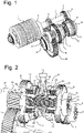
Fig. 1 shows a perspective view of an electromotor and a gear assembly according to the invention, - 0021
Fig. 2 shows the gears and clutches on an intermediate shaft according to the invention, - 0022
Fig. 3 shows a perspective view of the housing of the electromotor and the gear assembly interconnected via an interconnecting plate according to the invention, - 0023
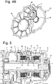
Figs. 4a and4b show perspective views of the interconnecting plate according to the invention, and - 0024
Fig. 5 shows a partial cross-sectional view of the gear assembly offig. 1 . - 0025
Figure 1 shows an electric motor 1 comprising adriving shaft 2 that is mounted inbearings 4, 5. Thedriving shaft 2 has fixed thereongears 6,7 of the first stage of the gearbox, which mesh with matchinggears gears shaft 15 and can viawet clutches shaft 15, that is supported bybearings intermediate shaft 15 drivesgears intermediate shaft 15 is between about 1.5 and 2.5 times lower than the rotational speed of thedriving shaft 2. - 0026
Figure 2 shows theclutches intermediate shaft 15. Thegears shaft 15 via a clearance fit 22, 23, so that they can freely spin. Theouter drums clutch gears inner drums clutches shaft 15 via splines in a fixed angular position. Theinner drums clutch discs clutch discs outer drums - 0027 By compression of the stacks of
adjacent clutch discs outer drums rings discs clutches shaft 15 with one of thegears rings - 0028 As schematically indicated in
figure 2 , therings ducts hydraulic actuators controller 40. Therings annular groove plate 46 of the housing of the gear box and are in fluid-tight contact with the walls of these annular grooves viacircumferential seals - 0029 The
controller 40 operates the axial displacement of therings rings shaft 15, while the other clutch starts to slip and engages therotating shaft 15 until it is in a fixed angular position relative to theshaft 15. In this way, a smooth transition of the torque that is exerted on theshaft 15 from onegear - 0030
Figure 3 shows themotor housing 45, thegear box housing 47 and the interconnectingplate 46 that is connected at the interface 44 via bolts that are interconnecting thehousing parts fig. 4a , the interconnectingplate 46 is at the side facing themotor housing 45 provided with anannular groove 51 for accommodating thering 34 of the clutch 11. Thedrive shaft 2 passes through thehole 49, whereas theintermediate shaft 15 passes throughopening 48 andopening 50 accommodates theoutput shaft 55. At the interface 44, holes 53 are provided along the circumference of theplate 46 for receiving connecting bolts interconnecting thehousing parts - 0031 As shown in
figure 4b , the interconnectingplate 46 is at the outward facing side provided with anannular groove 52 for accommodating thering 33 of the clutch 10. - 0032
Figure 5 shows theclutches midpoint 57 of theshaft 15 whereas thegears bearings - 0033 While the invention has been described with reference to exemplary embodiments, it will be understood by those skilled in the art that various changes may be made and equivalents may be substituted for elements thereof without departing from the scope of the invention. The controller disclosed can include a special purpose computer (which could include one or more processors and/or memory) programmed to perform the required steps. In addition, many modifications may be made to adapt a particular situation or material to the teachings of the invention without departing from the essential scope thereof. Therefore, it is intended that the invention not be limited to the particular or preferred embodiments disclosed, but that the invention will include all embodiments falling within the scope of the appended claims.
Claims (10)
- Gear assembly for use with an electric motor (1) comprising a shaft (15) with a rotatable gear (8,9) both on a first end and on a second end, each gear connected to a first clutch member (24,25) fixedly connected to the gear (8,9) and the first clutch members being connectable to a second clutch member (26,27) extending around the shaft (15) and connected to the shaft in a fixed angular position, a force member (33,34, 37,38,46) being axially situated between the clutch members (10,11) for axially moving the second clutch members (26,27) relative to the first clutch members (24,25) in an axial direction such that the first clutch members (24,25) and the second clutch members (26,27) can engage and disengage in a slipping manner at relative circumferential speeds.
- Gear assembly according to claim 1, the shaft (15) being supported by bearings (16,17) at each end of the shaft (15) near a respective gear (8,9).
- Gear assembly according to claim 1 or 2, wherein the gears (8,9) are mounted on the shaft (15) with a clearance fit so they can freely rotate around the shaft (15).
- Gear assembly according to any of the preceding claims, the second clutch members (26,27) extending around the shaft (15) and being situated closer to a midpoint (57) of the shaft (15) than the gears (8,9).
- Gear assembly according to any of the preceding claims comprising a controller (40) such that one of the second clutch members (26,27) engages its corresponding first clutch member (24,25) while the other of the second clutch members (26,27) disengages from its corresponding first clutch member (24,25) such that a transfer of torque from the gears (8,9) to the shaft (15) is substantially constant.
- Gear assembly according to any of the preceding claims, the force member (33,34, 37,38,46) comprising for each second clutch member (26,27) a hydraulic actuator (33,34,51,52).
- Gear assembly according to claim 6, placed in a housing having a first and a second housing segment (45,47) and an interconnecting plate (46) situated at an interface (44) between the housing segments (45,47), the interconnecting plate (46) supporting the hydraulic actuators (33,34,51,52).
- Gear assembly according to claim 7, wherein the hydraulic actuators comprise a ring-shaped groove (51,52) in the interconnecting plate (46).
- Interconnecting plate (46) for use in a gear assembly according to claim 7 or 8, the interconnecting plate comprising ring-shaped grooves (51,52) and oil channels (35,36) connecting to the grooves (51,52), wherein the ring shaped groves and oil channels are formed in the interconnecting plate material.
- Electric vehicle comprising an electric motor (1) and a gear assembly according to any of claims 1-8.
Priority Applications (3)
| Application Number | Priority Date | Filing Date | Title |
|---|---|---|---|
| EP20208649.2A EP4001684B1 (en) | 2020-11-19 | 2020-11-19 | Two-speed gearbox for an electric motor |
| US17/526,029 US11898624B2 (en) | 2020-11-19 | 2021-11-15 | Two-speed gearbox for an electric motor |
| CN202111373718.1A CN114517827B (en) | 2020-11-19 | 2021-11-19 | Two-speed gearbox for an electric motor |
Applications Claiming Priority (1)
| Application Number | Priority Date | Filing Date | Title |
|---|---|---|---|
| EP20208649.2A EP4001684B1 (en) | 2020-11-19 | 2020-11-19 | Two-speed gearbox for an electric motor |
Publications (2)
| Publication Number | Publication Date |
|---|---|
| EP4001684A1 true EP4001684A1 (en) | 2022-05-25 |
| EP4001684B1 EP4001684B1 (en) | 2024-01-03 |
Family
ID=73497613
Family Applications (1)
| Application Number | Title | Priority Date | Filing Date |
|---|---|---|---|
| EP20208649.2A Active EP4001684B1 (en) | 2020-11-19 | 2020-11-19 | Two-speed gearbox for an electric motor |
Country Status (3)
| Country | Link |
|---|---|
| US (1) | US11898624B2 (en) |
| EP (1) | EP4001684B1 (en) |
| CN (1) | CN114517827B (en) |
Citations (3)
| Publication number | Priority date | Publication date | Assignee | Title |
|---|---|---|---|---|
| EP2151602A1 (en) * | 2007-08-21 | 2010-02-10 | Yamaha Hatsudoki Kabushiki Kaisha | Stepped automatic transmission and vehicle with the same |
| US20180266497A1 (en) * | 2017-03-20 | 2018-09-20 | Deere & Company | Work vehicle transmission disconnect device control with shaft mounted manifold |
| EP3428480A2 (en) * | 2017-06-22 | 2019-01-16 | Kubota Corporation | Work vehicle transmission and work vehicle having the same |
Family Cites Families (14)
| Publication number | Priority date | Publication date | Assignee | Title |
|---|---|---|---|---|
| DE19917724C2 (en) * | 1999-04-20 | 2003-01-02 | Getrag Getriebe Zahnrad | Drive train for a motor vehicle |
| US6790154B1 (en) * | 2003-03-21 | 2004-09-14 | Borgwarner, Inc. | Rear axle having electromagnetic clutches and geared differential |
| DE102005048938A1 (en) * | 2005-10-13 | 2007-04-19 | Volkswagen Ag | Dual clutch transmission for a motor vehicle, in particular with a hybrid drive or method for controlling this dual clutch transmission |
| TW201144636A (en) * | 2010-06-11 | 2011-12-16 | meng-hao Ji | Speed-change method and speed-change mechanism for electronic vehicle |
| JP5580217B2 (en) * | 2011-01-07 | 2014-08-27 | Ntn株式会社 | VEHICLE MOTOR DRIVE DEVICE AND AUTOMOBILE |
| DE102012010170B4 (en) * | 2012-05-19 | 2018-10-04 | GETRAG B.V. & Co. KG | Coupling arrangement and two-speed transmission |
| US9574619B1 (en) * | 2015-11-12 | 2017-02-21 | Gm Global Technology Operations, Llc | Pawl grounding clutch with synchronizer |
| TWI615294B (en) * | 2016-01-15 | 2018-02-21 | 財團法人工業技術研究院 | Two-speed transmission for electric vehicle having two clutches |
| TWI610832B (en) * | 2016-01-15 | 2018-01-11 | 財團法人工業技術研究院 | Two-speed transmission having two clutches |
| CN107191552A (en) * | 2017-06-06 | 2017-09-22 | 重庆长安汽车股份有限公司 | A kind of double-clutch automatic gearbox transmission device |
| WO2019152065A1 (en) * | 2018-02-02 | 2019-08-08 | Dana Automotive Systems Group, Llc | Electric drive axle with multi-speed gearbox |
| DE202019105419U1 (en) * | 2018-10-01 | 2020-02-10 | Dana Automotive Systems Group, Llc | Multi-speed manual transmission and drive axle made with it |
| US11015689B2 (en) * | 2019-02-18 | 2021-05-25 | Ford Global Technologies, Llc | Multi-speed electric machine gearbox with low drive ratio |
| DE102020202786A1 (en) * | 2019-03-14 | 2020-10-22 | Dana Automotive Systems Group, Llc | MULTI-SPEED MANUAL GEARBOX WITH ONE GEAR-CLUTCH ASSEMBLY |
-
2020
- 2020-11-19 EP EP20208649.2A patent/EP4001684B1/en active Active
-
2021
- 2021-11-15 US US17/526,029 patent/US11898624B2/en active Active
- 2021-11-19 CN CN202111373718.1A patent/CN114517827B/en active Active
Patent Citations (3)
| Publication number | Priority date | Publication date | Assignee | Title |
|---|---|---|---|---|
| EP2151602A1 (en) * | 2007-08-21 | 2010-02-10 | Yamaha Hatsudoki Kabushiki Kaisha | Stepped automatic transmission and vehicle with the same |
| US20180266497A1 (en) * | 2017-03-20 | 2018-09-20 | Deere & Company | Work vehicle transmission disconnect device control with shaft mounted manifold |
| EP3428480A2 (en) * | 2017-06-22 | 2019-01-16 | Kubota Corporation | Work vehicle transmission and work vehicle having the same |
Also Published As
| Publication number | Publication date |
|---|---|
| CN114517827B (en) | 2024-01-23 |
| US11898624B2 (en) | 2024-02-13 |
| US20220154805A1 (en) | 2022-05-19 |
| CN114517827A (en) | 2022-05-20 |
| EP4001684B1 (en) | 2024-01-03 |
Similar Documents
| Publication | Publication Date | Title |
|---|---|---|
| USRE46242E1 (en) | Device for actuating a gearwheel, which is designed as a loose wheel, of a transmission device | |
| CN113498458B (en) | Multi-axis gearbox | |
| EP3256755B1 (en) | Twin countershaft transmission with spline | |
| EP2457000B1 (en) | Transmission module for a vehicle | |
| US8235194B2 (en) | Multiple friction member synchronizing clutch | |
| US5367914A (en) | Power transmission having creeping speed by concurrent suppling engagement of the dual input plate clutches of the countershafts | |
| KR20040086784A (en) | Synchronizer having ball ramp actuator mechanism | |
| CN109641519B (en) | PTO drive gear thrust load offset | |
| US8960032B2 (en) | Multi-clutch transmission for a motor vehicle | |
| US20220136569A1 (en) | Torque transmission device for a motor vehicle | |
| US20220144069A1 (en) | Clutch Assembly, Motor Vehicle Powertrain, and Method for Operating a Powertrain | |
| EP2935926B1 (en) | Clutch arrangement comprising a shift piston and a piston housing | |
| JP5606538B2 (en) | Uncouple drive mechanism | |
| US5353661A (en) | Power transmission with coaxial input and output shafts supported at one end of each shaft by a floating bearing support | |
| CN114604077A (en) | Hybrid drive sub-assemblies for vehicles | |
| US5347879A (en) | Power transmission | |
| US11898624B2 (en) | Two-speed gearbox for an electric motor | |
| EP4055302B1 (en) | Transmission assembly for a vehicle | |
| US20150354700A1 (en) | Automatic transmission | |
| EP2843260A1 (en) | Automatic manual transmission | |
| CN100476244C (en) | automatic transmission | |
| EP3430289A1 (en) | Shift control arrangement in a gearbox | |
| EP3864321B1 (en) | Gearbox for vehicles and vehicles comprising such a gearbox | |
| US6289757B1 (en) | Synchronized gearbox | |
| CN118793749A (en) | Transmission mechanism |
Legal Events
| Date | Code | Title | Description |
|---|---|---|---|
| PUAI | Public reference made under article 153(3) epc to a published international application that has entered the european phase |
Free format text: ORIGINAL CODE: 0009012 |
|
| STAA | Information on the status of an ep patent application or granted ep patent |
Free format text: STATUS: THE APPLICATION HAS BEEN PUBLISHED |
|
| AK | Designated contracting states |
Kind code of ref document: A1 Designated state(s): AL AT BE BG CH CY CZ DE DK EE ES FI FR GB GR HR HU IE IS IT LI LT LU LV MC MK MT NL NO PL PT RO RS SE SI SK SM TR |
|
| STAA | Information on the status of an ep patent application or granted ep patent |
Free format text: STATUS: REQUEST FOR EXAMINATION WAS MADE |
|
| 17P | Request for examination filed |
Effective date: 20221108 |
|
| RBV | Designated contracting states (corrected) |
Designated state(s): AL AT BE BG CH CY CZ DE DK EE ES FI FR GB GR HR HU IE IS IT LI LT LU LV MC MK MT NL NO PL PT RO RS SE SI SK SM TR |
|
| RIC1 | Information provided on ipc code assigned before grant |
Ipc: F16D 21/04 20060101ALI20230525BHEP Ipc: F16D 25/0638 20060101AFI20230525BHEP |
|
| GRAP | Despatch of communication of intention to grant a patent |
Free format text: ORIGINAL CODE: EPIDOSNIGR1 |
|
| STAA | Information on the status of an ep patent application or granted ep patent |
Free format text: STATUS: GRANT OF PATENT IS INTENDED |
|
| INTG | Intention to grant announced |
Effective date: 20230719 |
|
| GRAS | Grant fee paid |
Free format text: ORIGINAL CODE: EPIDOSNIGR3 |
|
| GRAA | (expected) grant |
Free format text: ORIGINAL CODE: 0009210 |
|
| STAA | Information on the status of an ep patent application or granted ep patent |
Free format text: STATUS: THE PATENT HAS BEEN GRANTED |
|
| P01 | Opt-out of the competence of the unified patent court (upc) registered |
Effective date: 20231122 |
|
| AK | Designated contracting states |
Kind code of ref document: B1 Designated state(s): AL AT BE BG CH CY CZ DE DK EE ES FI FR GB GR HR HU IE IS IT LI LT LU LV MC MK MT NL NO PL PT RO RS SE SI SK SM TR |
|
| REG | Reference to a national code |
Ref country code: GB Ref legal event code: FG4D |
|
| REG | Reference to a national code |
Ref country code: CH Ref legal event code: EP |
|
| REG | Reference to a national code |
Ref country code: DE Ref legal event code: R096 Ref document number: 602020023759 Country of ref document: DE |
|
| REG | Reference to a national code |
Ref country code: IE Ref legal event code: FG4D |
|
| REG | Reference to a national code |
Ref country code: LT Ref legal event code: MG9D |
|
| PG25 | Lapsed in a contracting state [announced via postgrant information from national office to epo] |
Ref country code: ES Free format text: LAPSE BECAUSE OF FAILURE TO SUBMIT A TRANSLATION OF THE DESCRIPTION OR TO PAY THE FEE WITHIN THE PRESCRIBED TIME-LIMIT Effective date: 20240103 |
|
| PG25 | Lapsed in a contracting state [announced via postgrant information from national office to epo] |
Ref country code: ES Free format text: LAPSE BECAUSE OF FAILURE TO SUBMIT A TRANSLATION OF THE DESCRIPTION OR TO PAY THE FEE WITHIN THE PRESCRIBED TIME-LIMIT Effective date: 20240103 |
|
| REG | Reference to a national code |
Ref country code: NL Ref legal event code: MP Effective date: 20240103 |
|
| REG | Reference to a national code |
Ref country code: AT Ref legal event code: MK05 Ref document number: 1647082 Country of ref document: AT Kind code of ref document: T Effective date: 20240103 |
|
| PG25 | Lapsed in a contracting state [announced via postgrant information from national office to epo] |
Ref country code: NL Free format text: LAPSE BECAUSE OF FAILURE TO SUBMIT A TRANSLATION OF THE DESCRIPTION OR TO PAY THE FEE WITHIN THE PRESCRIBED TIME-LIMIT Effective date: 20240103 |
|
| PG25 | Lapsed in a contracting state [announced via postgrant information from national office to epo] |
Ref country code: NL Free format text: LAPSE BECAUSE OF FAILURE TO SUBMIT A TRANSLATION OF THE DESCRIPTION OR TO PAY THE FEE WITHIN THE PRESCRIBED TIME-LIMIT Effective date: 20240103 |
|
| PG25 | Lapsed in a contracting state [announced via postgrant information from national office to epo] |
Ref country code: IS Free format text: LAPSE BECAUSE OF FAILURE TO SUBMIT A TRANSLATION OF THE DESCRIPTION OR TO PAY THE FEE WITHIN THE PRESCRIBED TIME-LIMIT Effective date: 20240503 |
|
| PG25 | Lapsed in a contracting state [announced via postgrant information from national office to epo] |
Ref country code: LT Free format text: LAPSE BECAUSE OF FAILURE TO SUBMIT A TRANSLATION OF THE DESCRIPTION OR TO PAY THE FEE WITHIN THE PRESCRIBED TIME-LIMIT Effective date: 20240103 |
|
| PG25 | Lapsed in a contracting state [announced via postgrant information from national office to epo] |
Ref country code: GR Free format text: LAPSE BECAUSE OF FAILURE TO SUBMIT A TRANSLATION OF THE DESCRIPTION OR TO PAY THE FEE WITHIN THE PRESCRIBED TIME-LIMIT Effective date: 20240404 |
|
| PG25 | Lapsed in a contracting state [announced via postgrant information from national office to epo] |
Ref country code: HR Free format text: LAPSE BECAUSE OF FAILURE TO SUBMIT A TRANSLATION OF THE DESCRIPTION OR TO PAY THE FEE WITHIN THE PRESCRIBED TIME-LIMIT Effective date: 20240103 Ref country code: RS Free format text: LAPSE BECAUSE OF FAILURE TO SUBMIT A TRANSLATION OF THE DESCRIPTION OR TO PAY THE FEE WITHIN THE PRESCRIBED TIME-LIMIT Effective date: 20240403 |
|
| PG25 | Lapsed in a contracting state [announced via postgrant information from national office to epo] |
Ref country code: CZ Free format text: LAPSE BECAUSE OF FAILURE TO SUBMIT A TRANSLATION OF THE DESCRIPTION OR TO PAY THE FEE WITHIN THE PRESCRIBED TIME-LIMIT Effective date: 20240103 Ref country code: AT Free format text: LAPSE BECAUSE OF FAILURE TO SUBMIT A TRANSLATION OF THE DESCRIPTION OR TO PAY THE FEE WITHIN THE PRESCRIBED TIME-LIMIT Effective date: 20240103 |
|
| PG25 | Lapsed in a contracting state [announced via postgrant information from national office to epo] |
Ref country code: RS Free format text: LAPSE BECAUSE OF FAILURE TO SUBMIT A TRANSLATION OF THE DESCRIPTION OR TO PAY THE FEE WITHIN THE PRESCRIBED TIME-LIMIT Effective date: 20240403 Ref country code: NO Free format text: LAPSE BECAUSE OF FAILURE TO SUBMIT A TRANSLATION OF THE DESCRIPTION OR TO PAY THE FEE WITHIN THE PRESCRIBED TIME-LIMIT Effective date: 20240403 Ref country code: LT Free format text: LAPSE BECAUSE OF FAILURE TO SUBMIT A TRANSLATION OF THE DESCRIPTION OR TO PAY THE FEE WITHIN THE PRESCRIBED TIME-LIMIT Effective date: 20240103 Ref country code: IS Free format text: LAPSE BECAUSE OF FAILURE TO SUBMIT A TRANSLATION OF THE DESCRIPTION OR TO PAY THE FEE WITHIN THE PRESCRIBED TIME-LIMIT Effective date: 20240503 Ref country code: HR Free format text: LAPSE BECAUSE OF FAILURE TO SUBMIT A TRANSLATION OF THE DESCRIPTION OR TO PAY THE FEE WITHIN THE PRESCRIBED TIME-LIMIT Effective date: 20240103 Ref country code: GR Free format text: LAPSE BECAUSE OF FAILURE TO SUBMIT A TRANSLATION OF THE DESCRIPTION OR TO PAY THE FEE WITHIN THE PRESCRIBED TIME-LIMIT Effective date: 20240404 Ref country code: CZ Free format text: LAPSE BECAUSE OF FAILURE TO SUBMIT A TRANSLATION OF THE DESCRIPTION OR TO PAY THE FEE WITHIN THE PRESCRIBED TIME-LIMIT Effective date: 20240103 Ref country code: BG Free format text: LAPSE BECAUSE OF FAILURE TO SUBMIT A TRANSLATION OF THE DESCRIPTION OR TO PAY THE FEE WITHIN THE PRESCRIBED TIME-LIMIT Effective date: 20240103 Ref country code: AT Free format text: LAPSE BECAUSE OF FAILURE TO SUBMIT A TRANSLATION OF THE DESCRIPTION OR TO PAY THE FEE WITHIN THE PRESCRIBED TIME-LIMIT Effective date: 20240103 |
|
| PG25 | Lapsed in a contracting state [announced via postgrant information from national office to epo] |
Ref country code: PT Free format text: LAPSE BECAUSE OF FAILURE TO SUBMIT A TRANSLATION OF THE DESCRIPTION OR TO PAY THE FEE WITHIN THE PRESCRIBED TIME-LIMIT Effective date: 20240503 Ref country code: PL Free format text: LAPSE BECAUSE OF FAILURE TO SUBMIT A TRANSLATION OF THE DESCRIPTION OR TO PAY THE FEE WITHIN THE PRESCRIBED TIME-LIMIT Effective date: 20240103 |
|
| PG25 | Lapsed in a contracting state [announced via postgrant information from national office to epo] |
Ref country code: SE Free format text: LAPSE BECAUSE OF FAILURE TO SUBMIT A TRANSLATION OF THE DESCRIPTION OR TO PAY THE FEE WITHIN THE PRESCRIBED TIME-LIMIT Effective date: 20240103 Ref country code: PT Free format text: LAPSE BECAUSE OF FAILURE TO SUBMIT A TRANSLATION OF THE DESCRIPTION OR TO PAY THE FEE WITHIN THE PRESCRIBED TIME-LIMIT Effective date: 20240503 Ref country code: PL Free format text: LAPSE BECAUSE OF FAILURE TO SUBMIT A TRANSLATION OF THE DESCRIPTION OR TO PAY THE FEE WITHIN THE PRESCRIBED TIME-LIMIT Effective date: 20240103 Ref country code: LV Free format text: LAPSE BECAUSE OF FAILURE TO SUBMIT A TRANSLATION OF THE DESCRIPTION OR TO PAY THE FEE WITHIN THE PRESCRIBED TIME-LIMIT Effective date: 20240103 |
|
| REG | Reference to a national code |
Ref country code: DE Ref legal event code: R097 Ref document number: 602020023759 Country of ref document: DE |
|
| PG25 | Lapsed in a contracting state [announced via postgrant information from national office to epo] |
Ref country code: DK Free format text: LAPSE BECAUSE OF FAILURE TO SUBMIT A TRANSLATION OF THE DESCRIPTION OR TO PAY THE FEE WITHIN THE PRESCRIBED TIME-LIMIT Effective date: 20240103 |
|
| PG25 | Lapsed in a contracting state [announced via postgrant information from national office to epo] |
Ref country code: SM Free format text: LAPSE BECAUSE OF FAILURE TO SUBMIT A TRANSLATION OF THE DESCRIPTION OR TO PAY THE FEE WITHIN THE PRESCRIBED TIME-LIMIT Effective date: 20240103 |
|
| PG25 | Lapsed in a contracting state [announced via postgrant information from national office to epo] |
Ref country code: EE Free format text: LAPSE BECAUSE OF FAILURE TO SUBMIT A TRANSLATION OF THE DESCRIPTION OR TO PAY THE FEE WITHIN THE PRESCRIBED TIME-LIMIT Effective date: 20240103 |
|
| PG25 | Lapsed in a contracting state [announced via postgrant information from national office to epo] |
Ref country code: SK Free format text: LAPSE BECAUSE OF FAILURE TO SUBMIT A TRANSLATION OF THE DESCRIPTION OR TO PAY THE FEE WITHIN THE PRESCRIBED TIME-LIMIT Effective date: 20240103 |
|
| PG25 | Lapsed in a contracting state [announced via postgrant information from national office to epo] |
Ref country code: SM Free format text: LAPSE BECAUSE OF FAILURE TO SUBMIT A TRANSLATION OF THE DESCRIPTION OR TO PAY THE FEE WITHIN THE PRESCRIBED TIME-LIMIT Effective date: 20240103 Ref country code: SK Free format text: LAPSE BECAUSE OF FAILURE TO SUBMIT A TRANSLATION OF THE DESCRIPTION OR TO PAY THE FEE WITHIN THE PRESCRIBED TIME-LIMIT Effective date: 20240103 Ref country code: RO Free format text: LAPSE BECAUSE OF FAILURE TO SUBMIT A TRANSLATION OF THE DESCRIPTION OR TO PAY THE FEE WITHIN THE PRESCRIBED TIME-LIMIT Effective date: 20240103 Ref country code: EE Free format text: LAPSE BECAUSE OF FAILURE TO SUBMIT A TRANSLATION OF THE DESCRIPTION OR TO PAY THE FEE WITHIN THE PRESCRIBED TIME-LIMIT Effective date: 20240103 Ref country code: DK Free format text: LAPSE BECAUSE OF FAILURE TO SUBMIT A TRANSLATION OF THE DESCRIPTION OR TO PAY THE FEE WITHIN THE PRESCRIBED TIME-LIMIT Effective date: 20240103 |
|
| PLBE | No opposition filed within time limit |
Free format text: ORIGINAL CODE: 0009261 |
|
| STAA | Information on the status of an ep patent application or granted ep patent |
Free format text: STATUS: NO OPPOSITION FILED WITHIN TIME LIMIT |
|
| PG25 | Lapsed in a contracting state [announced via postgrant information from national office to epo] |
Ref country code: IT Free format text: LAPSE BECAUSE OF FAILURE TO SUBMIT A TRANSLATION OF THE DESCRIPTION OR TO PAY THE FEE WITHIN THE PRESCRIBED TIME-LIMIT Effective date: 20240103 |
|
| 26N | No opposition filed |
Effective date: 20241007 |
|
| PG25 | Lapsed in a contracting state [announced via postgrant information from national office to epo] |
Ref country code: IT Free format text: LAPSE BECAUSE OF FAILURE TO SUBMIT A TRANSLATION OF THE DESCRIPTION OR TO PAY THE FEE WITHIN THE PRESCRIBED TIME-LIMIT Effective date: 20240103 |
|
| PG25 | Lapsed in a contracting state [announced via postgrant information from national office to epo] |
Ref country code: SI Free format text: LAPSE BECAUSE OF FAILURE TO SUBMIT A TRANSLATION OF THE DESCRIPTION OR TO PAY THE FEE WITHIN THE PRESCRIBED TIME-LIMIT Effective date: 20240103 |
|
| REG | Reference to a national code |
Ref country code: CH Ref legal event code: PL |
|
| PG25 | Lapsed in a contracting state [announced via postgrant information from national office to epo] |
Ref country code: MC Free format text: LAPSE BECAUSE OF FAILURE TO SUBMIT A TRANSLATION OF THE DESCRIPTION OR TO PAY THE FEE WITHIN THE PRESCRIBED TIME-LIMIT Effective date: 20240103 |
|
| PG25 | Lapsed in a contracting state [announced via postgrant information from national office to epo] |
Ref country code: LU Free format text: LAPSE BECAUSE OF NON-PAYMENT OF DUE FEES Effective date: 20241119 |
|
| REG | Reference to a national code |
Ref country code: CH Ref legal event code: PL |
|
| PG25 | Lapsed in a contracting state [announced via postgrant information from national office to epo] |
Ref country code: CH Free format text: LAPSE BECAUSE OF NON-PAYMENT OF DUE FEES Effective date: 20241130 |
|
| REG | Reference to a national code |
Ref country code: BE Ref legal event code: MM Effective date: 20241130 |
|
| PG25 | Lapsed in a contracting state [announced via postgrant information from national office to epo] |
Ref country code: FI Free format text: LAPSE BECAUSE OF FAILURE TO SUBMIT A TRANSLATION OF THE DESCRIPTION OR TO PAY THE FEE WITHIN THE PRESCRIBED TIME-LIMIT Effective date: 20240103 |
|
| PG25 | Lapsed in a contracting state [announced via postgrant information from national office to epo] |
Ref country code: BE Free format text: LAPSE BECAUSE OF NON-PAYMENT OF DUE FEES Effective date: 20241130 |
|
| PG25 | Lapsed in a contracting state [announced via postgrant information from national office to epo] |
Ref country code: IE Free format text: LAPSE BECAUSE OF NON-PAYMENT OF DUE FEES Effective date: 20241119 |
|
| PGFP | Annual fee paid to national office [announced via postgrant information from national office to epo] |
Ref country code: DE Payment date: 20251022 Year of fee payment: 6 |
|
| PGFP | Annual fee paid to national office [announced via postgrant information from national office to epo] |
Ref country code: GB Payment date: 20251023 Year of fee payment: 6 |
|
| PGFP | Annual fee paid to national office [announced via postgrant information from national office to epo] |
Ref country code: FR Payment date: 20251022 Year of fee payment: 6 |
|
| PG25 | Lapsed in a contracting state [announced via postgrant information from national office to epo] |
Ref country code: HU Free format text: LAPSE BECAUSE OF FAILURE TO SUBMIT A TRANSLATION OF THE DESCRIPTION OR TO PAY THE FEE WITHIN THE PRESCRIBED TIME-LIMIT; INVALID AB INITIO Effective date: 20201119 |
|
| PG25 | Lapsed in a contracting state [announced via postgrant information from national office to epo] |
Ref country code: CY Free format text: LAPSE BECAUSE OF FAILURE TO SUBMIT A TRANSLATION OF THE DESCRIPTION OR TO PAY THE FEE WITHIN THE PRESCRIBED TIME-LIMIT; INVALID AB INITIO Effective date: 20201119 |