EP4001651B1 - Positive displacement roots blower noise suppression - Google Patents
Positive displacement roots blower noise suppression Download PDFInfo
- Publication number
- EP4001651B1 EP4001651B1 EP21208039.4A EP21208039A EP4001651B1 EP 4001651 B1 EP4001651 B1 EP 4001651B1 EP 21208039 A EP21208039 A EP 21208039A EP 4001651 B1 EP4001651 B1 EP 4001651B1
- Authority
- EP
- European Patent Office
- Prior art keywords
- inlet
- venturi
- outlet
- closed
- feedback
- Prior art date
- Legal status (The legal status is an assumption and is not a legal conclusion. Google has not performed a legal analysis and makes no representation as to the accuracy of the status listed.)
- Active
Links
Images









Classifications
-
- F—MECHANICAL ENGINEERING; LIGHTING; HEATING; WEAPONS; BLASTING
- F04—POSITIVE - DISPLACEMENT MACHINES FOR LIQUIDS; PUMPS FOR LIQUIDS OR ELASTIC FLUIDS
- F04C—ROTARY-PISTON, OR OSCILLATING-PISTON, POSITIVE-DISPLACEMENT MACHINES FOR LIQUIDS; ROTARY-PISTON, OR OSCILLATING-PISTON, POSITIVE-DISPLACEMENT PUMPS
- F04C18/00—Rotary-piston pumps specially adapted for elastic fluids
- F04C18/08—Rotary-piston pumps specially adapted for elastic fluids of intermeshing-engagement type, i.e. with engagement of co-operating members similar to that of toothed gearing
- F04C18/12—Rotary-piston pumps specially adapted for elastic fluids of intermeshing-engagement type, i.e. with engagement of co-operating members similar to that of toothed gearing of other than internal-axis type
- F04C18/126—Rotary-piston pumps specially adapted for elastic fluids of intermeshing-engagement type, i.e. with engagement of co-operating members similar to that of toothed gearing of other than internal-axis type with radially from the rotor body extending elements, not necessarily co-operating with corresponding recesses in the other rotor, e.g. lobes, Roots type
-
- F—MECHANICAL ENGINEERING; LIGHTING; HEATING; WEAPONS; BLASTING
- F04—POSITIVE - DISPLACEMENT MACHINES FOR LIQUIDS; PUMPS FOR LIQUIDS OR ELASTIC FLUIDS
- F04C—ROTARY-PISTON, OR OSCILLATING-PISTON, POSITIVE-DISPLACEMENT MACHINES FOR LIQUIDS; ROTARY-PISTON, OR OSCILLATING-PISTON, POSITIVE-DISPLACEMENT PUMPS
- F04C29/00—Component parts, details or accessories of pumps or pumping installations, not provided for in groups F04C18/00 - F04C28/00
- F04C29/0021—Systems for the equilibration of forces acting on the pump
- F04C29/0035—Equalization of pressure pulses
-
- F—MECHANICAL ENGINEERING; LIGHTING; HEATING; WEAPONS; BLASTING
- F04—POSITIVE - DISPLACEMENT MACHINES FOR LIQUIDS; PUMPS FOR LIQUIDS OR ELASTIC FLUIDS
- F04C—ROTARY-PISTON, OR OSCILLATING-PISTON, POSITIVE-DISPLACEMENT MACHINES FOR LIQUIDS; ROTARY-PISTON, OR OSCILLATING-PISTON, POSITIVE-DISPLACEMENT PUMPS
- F04C25/00—Adaptations of pumps for special use of pumps for elastic fluids
-
- F—MECHANICAL ENGINEERING; LIGHTING; HEATING; WEAPONS; BLASTING
- F04—POSITIVE - DISPLACEMENT MACHINES FOR LIQUIDS; PUMPS FOR LIQUIDS OR ELASTIC FLUIDS
- F04C—ROTARY-PISTON, OR OSCILLATING-PISTON, POSITIVE-DISPLACEMENT MACHINES FOR LIQUIDS; ROTARY-PISTON, OR OSCILLATING-PISTON, POSITIVE-DISPLACEMENT PUMPS
- F04C29/00—Component parts, details or accessories of pumps or pumping installations, not provided for in groups F04C18/00 - F04C28/00
- F04C29/12—Arrangements for admission or discharge of the working fluid, e.g. constructional features of the inlet or outlet
- F04C29/122—Arrangements for supercharging the working space
-
- F—MECHANICAL ENGINEERING; LIGHTING; HEATING; WEAPONS; BLASTING
- F04—POSITIVE - DISPLACEMENT MACHINES FOR LIQUIDS; PUMPS FOR LIQUIDS OR ELASTIC FLUIDS
- F04C—ROTARY-PISTON, OR OSCILLATING-PISTON, POSITIVE-DISPLACEMENT MACHINES FOR LIQUIDS; ROTARY-PISTON, OR OSCILLATING-PISTON, POSITIVE-DISPLACEMENT PUMPS
- F04C2240/00—Components
- F04C2240/20—Rotors
-
- F—MECHANICAL ENGINEERING; LIGHTING; HEATING; WEAPONS; BLASTING
- F04—POSITIVE - DISPLACEMENT MACHINES FOR LIQUIDS; PUMPS FOR LIQUIDS OR ELASTIC FLUIDS
- F04C—ROTARY-PISTON, OR OSCILLATING-PISTON, POSITIVE-DISPLACEMENT MACHINES FOR LIQUIDS; ROTARY-PISTON, OR OSCILLATING-PISTON, POSITIVE-DISPLACEMENT PUMPS
- F04C29/00—Component parts, details or accessories of pumps or pumping installations, not provided for in groups F04C18/00 - F04C28/00
- F04C29/06—Silencing
Definitions
- Roots-type blowers also referred to as roots blowers are positive displacement pumps that pump fluid through a pair of engaging rotors.
- a roots blower is one form of a positive displacement compressor that can be operated as an air compressor or as a vacuum pump. Roots blowers are easier to manufacturer than a screw compressor, less expensive, and more robust (tolerant) to the ingestion of debris that sometimes enters the compressor. Roots blowers find many applications in industry because they are oil-free compressors. Some of the applications for roots blowers are in the food processing industries, wastewater treatment plants, pumping dry goods into tanker trucks, and vacuum pumps used in street cleaners.
- a positive displacement roots blower according to claim 1 comprising:
- Each of the respective operating volumes may have the following regions: open to the inlet/closed to the venturi feedback inlet/closed to the outlet; closed to the inlet/open to the venturi feedback inlet/closed to the outlet; and closed to the inlet/closed to the venturi feedback inlet/open to the outlet.
- the venturi feedback inlet may be structured as an elongated entry to the respective volumes.
- the venturi feedback inlet may be positioned between about 100 degrees and 140 degrees from a 12 o'clock position.
- the region where the operating volume is closed to the inlet/open to the venturi feedback inlet/closed to the outlet may occur over an arc length of rotation of one of the intermeshed rotating members of at least 35 degrees.
- the region where the operating volume is closed to the inlet/open to the venturi feedback inlet/closed to the outlet may occur over an arc length of rotation of one of the intermeshed rotating members of at least 60 degrees.
- the operating volume may be at a pressure equal to a static pressure in the outlet as the operating volume transitions from the region where the operating volume is closed to the inlet/open to the venturi feedback inlet/closed to the outlet to the region closed to the inlet/closed to the venturi feedback inlet/open to the outlet.
- the housing may further include an air reservoir located proximate to the inlet for furnishing air to the operating volume.
- the volume of the air reservoir may be at least approximately equal to the volume of the operating volume to be filled.
- the volume of the air reservoir may be greater than the volume of the operating volume to be filled.
- This disclosure also relates to an apparatus comprising:
- the feedback loops may comprise a convergent-divergent passage having a throat, the throat forming a restriction.
- the feedback loop inlets may be in the form of elongate openings in the positive displacement roots blower, the elongate openings in fluid communication with the volume when each of the pair of counter rotational rotors are in the pressure equalization position.
- the volume may be formed over an angular range of motion of the adjacent lobes of at least 45 degrees.
- the pressure equalization position of the adjacent lobes may form the volume open to the pressure relief passage when a trailing lobe of the adjacent lobes traverses an angle between 5 and 15 degrees after the inlet is closed.
- the positive displacement roots blower may further include a cooling air inlet disposed between the feedback loop inlet and the outlet, and wherein the pressure relief passage can be routed from a cooling air duct which feeds cooling air to the cooling air inlet.
- the method may further comprise rotating the first rotor through each of the following regions: open to the inlet/closed to the venturi feedback loop inlet/closed to the outlet; closed to the inlet/open to the venturi feedback loop inlet/closed to the outlet; and closed to the inlet/closed to the venturi feedback loop inlet/open to the outlet.
- the method may further comprise increasing the pressure of the volume created between adjacent lobes of the first rotor from atmospheric pressure when passing through the region open to the inlet/closed to the venturi feedback loop inlet/closed to the outlet to about 1 bar atm when reaching the region closed to the inlet/closed to the venturi feedback loop inlet/open to the outlet.
- the method may further comprise positioning the venturi feedback loop inlet between about 80 degrees and 140 degrees from a 12 o'clock position.
- positive displacement roots blowers in accordance with the present disclosure reduce the pressure pulsations at the discharge of the positive displacement roots blowers.
- the systems, techniques, and apparatus of the present disclosure use one or more venturi feedback loops to raise the pocket pressure from inlet to the current discharge pressure.
- the inlet pressure is less than the discharge pressure, and often the inlet pressure is at atmospheric pressure and the discharge pressure is near 1 bar gage.
- the systems, techniques, and apparatus herein can be described as a feedback loop created by the venturi from discharge to pocket.
- the feedback loop makes it possible for the pocket to equalize before opening completely to the discharge. This equalization process reduces pressure pulsations significantly.
- the pocket pressure is timed by the size of the venturi so that when the pocket closes at the inlet the venturi begins to raise the pocket pressure to equal the discharge pressure.
- these two pressures are nearly the same and as a result the pressure pulsation is significantly reduced.
- venturi typically is not in a sonic condition nor do the systems, techniques, and apparatus described herein necessarily operate the nozzle as a sonic nozzle. Instead, the venturi acts as a throttle to gradually let air into the pocket so the pressure does not suddenly change inside the pocket, defeating the purpose of reducing the pressure pulsations at the discharge.
- a positive displacement roots blower 10 without a venturi feedback loop having an inlet 12 structured to provide a fluid to a pair of intermeshed rotors 14 and 16, forming a pocket of fluid, the joint rotation of which in turn delivers the fluid to the outlet 18 for discharge from the blower 10.
- the pair of intermeshed rotors 14 and 16 are located within a housing 17.
- the rotors 14 and 16 include a two-dimensional cross-sectional profile which is then extruded along a third dimension (aligned with the axis of rotation).
- the roots blower 10 is structured to pull fluid from the inlet 12 and drive it toward the outlet 18.
- the rotors 14 and 16 are structured to capture a pocket of fluid from the inlet 12 and rotate the pocket to a position to expose the pocket to the outlet 18 to complete the process from inlet 12 to outlet 18.
- the pocket is trapped between lobes of each respective rotor and a surface of the housing which encloses the rotors.
- the formation of pressure pulsations can occur at the discharge of the positive displacement roots blower.
- a positive displacement roots blower can be operated in a configuration where the inlet is at atmospheric pressure and the discharge is connected to a pressurized tank.
- the roots blower can be operated in a configuration where the inlet is at less than atmospheric pressure (e.g., at vacuum pressure), and the discharge is at atmospheric pressure.
- a discharge silencer may no longer be needed, and, if an operator wants a very quiet running machine, the size of the silencer may be reduced.
- power may be increased by using a roots blower with one or more venturi feedback loops, e.g., by about 5% when compared to a roots blower without venturi feedback loops.
- the systems, techniques, and apparatus of the present disclosure may be particularly well suited to applications where noise and weight are critical factors.
- clock positions e.g. "6 o'clock”
- clock positions will be understood to be a clock position relative to the rotor 56 depicted in FIG. 2 , in which the rotor is rotating in the clockwise direction as viewed from the perspective of FIG. 2 .
- the 12 o'clock position will be understood as the position determined by first drawing a reference line between the inlet side intersection 78 of the arc path swept by the rotor 54 and rotor 56 and the outlet side intersection 80 of the arc path swept by the rotor 54 and rotor 56.
- a secondary line is then drawn orthogonal to the reference line which represents the 3 o'clock-9 o'clock clock axis.
- a clock reference line is then drawn orthogonal from the secondary line and offset from the reference line, in which the clock reference line is drawn to locate the top most and bottom most part of the arc that the rotor 56 travels through.
- angular measurements can either be absolute or relative measurements depending on the context, where the absolute angular measurements are referenced starting from the 12 o'clock positioned as determined above and which progresses in a clockwise direction.
- 12 o'clock is the same as 0 degrees; 3 o'clock is the same as 90 degrees; 6 o'clock is the same as 180 degrees, etc.
- the roots blower 50 has an inlet 52 and an outlet 58, e.g., as described with reference to FIG. 2 .
- the accumulation of air continuously added at the outlet increases the discharge pressure.
- the trapped pocket created by the opening and closing of the rotors is typically at atmospheric pressure.
- the built-in pressure ratio is the main factor used to determine how much change in pressure the blower will produce.
- the change in pressure is the difference between discharge and inlet.
- the illustrated example depicts respective rotors 54 and 56 each having three lobes, other examples can have a different number of lobes. For example, some examples can include four or five lobed rotors.
- FIG. 2 shows two venturi feedbacks 68, one on either side of the blower that feed air from the outlet 58 to the pocket.
- the venturi feedbacks 68 connect the outlet 58 of the roots blower 50 to the housing 57 surrounding the rotors 54 and 56 through a venturi feedback inlet 72.
- the venturi feedback 68 may connect the discharge at around the 4 o'clock position of the housing 57, but other starting positions are contemplated herein.
- the size and dimension of the air reservoir 88 may be equal to or greater than the pocket that will open and be filled. Both features can provide a reduction in the pressure pulsations.
- a venturi as described herein is a tube having a venturi ingress for incoming flow, a venturi egress for outgoing flow, and a tapering, constricted section between the venturi ingress and the venturi egress, where there is a smooth transition between the venturi ingress and the constricted section and between the constricted section and the venturi egress.
- the constricted section of the venturi may be positioned at a midpoint between the venturi ingress and the venturi egress or may be closer to one of the venturi ingress or the venturi egress.
- the tube forming the venturi has a first cross-sectional area (e.g., as a function of diameter for a circular tube) at the venturi ingress, a second cross-sectional area (e.g., as a function of diameter for a circular tube) at the constricted section, and a third cross-sectional area (e.g., as function of diameter for a circular tube) at the venturi egress, where the second cross-sectional area or tube diameter at the constricted section is smaller than the first and third cross-sectional areas or tube diameters at the venturi ingress and the venturi egress respectively.
- a first cross-sectional area e.g., as a function of diameter for a circular tube
- second cross-sectional area e.g., as a function of diameter for a circular tube
- a third cross-sectional area e.g., as function of diameter for a circular tube
- the first tube cross-sectional area or diameter at the venturi inlet may be smaller than, equal to, or greater than the third tube cross-sectional area or diameter at the venturi egress.
- the second tube cross-sectional area or diameter is smaller than the first and third cross-sectional areas or tube diameters.
- a venturi works on the principle of the Venturi Effect, which corresponds to the reduction in fluid pressure that results when the fluid flows through the constricted section of the tube. As the pressure of the fluid passing through the constricted section decreases, its velocity increases. As the flow leaves the constricted section of the tube, the velocity of the flow decreases as its pressure increases once again.
- a venturi tube may include more than one constricted section for restricting the flow of the fluid passing through the venturi feedback.
- Fig. 2 shows venturi feedbacks 68 having a venturi ingress 82, a constricted section 84, and a venturi egress 86.
- Venturi ingress 82 is connected to outlet 58 through a connecting tube 81.
- Venturi egress 86 is connected to the inside of the housing 57 through venturi inlet 72.
- the mass flow rate for a roots blower without a venturi feedback loop is compared to the mass flow rate for a roots blower with venturi feedback loops as described herein.
- the mass flow rate of the roots blower without the venturi feedback loop has both a positive and a negative flow direction, while the roots blower with the venturi feedback loop as described herein discharges air consistently in one direction.
- the peak-to-peak amplitudes of the mass flow rate of the roots blower without the venturi feedback loop are extreme when compared to the amplitudes of the roots blower with the venturi feedback loop.
- the venturi feedback(s) make a significant difference in how the compressor operates.
- the positive displacement roots blowers with venturi feedback loops as described herein can run smoothly with a steady air output streaming out at a uniform rate.
- the roots blower without the venturi feedback loop sucks and blows air with each rotation of the rotors, increasing the noise and pressure pulsations of the system.
- FIG. 3 show that the average mass flow rate of the two designs is not necessarily affected by the addition of the venturi feedback loop.
- pocket pressure during rotation is described. Different stages of pocket pressure as a pocket is opened, closed, and then discharged are shown.
- the dashed line shows the pocket pressure of a roots blower without a venturi feedback loop.
- the pressure in the pocket remains at the inlet pressure until the pocket is opened to the higher discharge pressure.
- the process of opening causes the pocket pressure to rapidly increase, which is the cause for the pressure pulsation in a roots blower without a venturi feedback loop.
- the solid line shows the pressure in the pocket of the roots blower with a venturi feedback loop as described herein.
- p 1 shows a pressure when the pocket is open to the atmosphere.
- the venturi feedback loop gradually increases the pocket pressure as the pocket rotates from inlet 52 to outlet 58, until it nearly equals with the discharge pressure.
- point p 2 shows an intermediate pressure as the pocket rotates from inlet 52 to outlet 58.
- point p 3 shows the pressure fluctuations inside the pocket as it opens to the outlet 58. The closer the pressure of the pocket is to the discharge pressure prior to opening to the outlet, the lower the pressure pulsation is at the discharge of the compressor.
- the locations of measurement points for a computational fluid dynamics (CFD) analysis of the positive displacement roots blower with venturi feedback are shown.
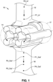
- FIG. 1 the locations of measurement points for a CFD analysis of the positive displacement roots blower without venturi feedback are shown.
- the pressure pulsation at point P1_In of the inlet of the roots blower of FIG. 2 is shown, compared to the pressure pulsation at P1_In' of the roots blower of FIG. 1 .
- the pressure pulsations at the inlet of the roots blower of FIG. 2 are initially reduced by the presence of the air reservoir 88. This is because the air reservoir 88 adds fluid capacity where needed, so that the air flowing into the roots blower is no longer vacuumed into the inlet as in the roots blower of FIG. 1 .
- the pressure pulsations at the outlets of the roots blower with the venturi feedback are shown at points P1_Out, P2_Out, P3_Out, and P4_Out compared respectively with points P1_Out', P2_Out', P3_Out', and P4_Out' of the roots blower without the venturi feedback.
- the pressure pulsations measured in bars, are decreased significantly in the roots blower with the venturi feedback, with the lowest levels of pulsation near point P4_Out of the discharge of the compressor where a silencer (not shown) may typically be positioned.
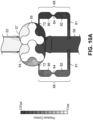
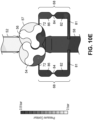
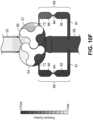
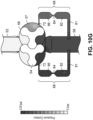
- FIGS. 10A-10H computational results are shown comparing the pressure inside the pockets at different orientations of the of lobes as the rotors 54 and 56 of the roots blower with venturi feedback of FIG. 1 rotate, starting at a relative angle of 0 degrees of the rotors in FIG. 10A and progressing in 10 degree increments throughout the remainder of FIGS. 10B-10H .
- the angle measurements shown in FIGS. 10A-10H are for convenience of illustration and do not correspond precisely to the measurements provided herein with respect to location of inlets and outlets as will be understood in the context of the description. In other words, 0 degrees in FIG. 10A does not necessarily correspond to the 12 o'clock position described above.
- FIG. 10A illustrates a position in which the rotor 56 is about to sweep past the inlet 52 and thereby close off and form a pocket between adjacent lobes of the rotor 56 (as shown in FIG. 10C ) which will be moved to the outlet 58 upon further rotation of the rotor 56.
- FIG. 10F shows rotor 54 venting the residual gas within the pocket to the outlet 58. It will be appreciated that the pressure in the pocket is lower than pressure of a gas at the outlet 58 in some modes of operation, while in other modes of operation, the pocket can be at a similar pressure to pressure of gas at the outlet at the moment of venting.
- the rotors 54 and 56 rotate through several regions which can be characterized by the location of its pocket and whether the pocket is in fluid communication with any respective passage such as the inlet 52, venturi feedbacks 68, and outlet 58.
- Region (1) can be characterized by the pocket being open to inlet 52, closed to venturi feedback inlet 72, and closed to outlet 58.
- Region (2) can be characterized by the pocket being closed to inlet 52, open to the venturi feedback inlet 72, and closed to outlet 58.
- Region (3) can be characterized as the pocket being closed to inlet 52, closed to venturi feedback inlet 72, and open to outlet 58.
- the arc length of travel associated with the rotors 54 and 56 in which the venturi feedback 68 increases the pressure of the pocket, and where over that arc length the pocket is sealed from the inlet 52 and the outlet 58 by virtue of the position of the rotor within the volume can be about 35 degrees in some examples, while in other examples it can be about 40, 45, 50, 55, 60, 65, 70, and 75 degrees, and in some examples can be up to about 90 degrees.
- different arc lengths of travel are contemplated depending on whether the rotor 56 is a three lobed or four lobed rotor (or possibly a rotor having other numbers of lobes).
- the term "sealed" as used in this context includes those situations in which the rotor may not be perfectly contacted along the entirely of the surface and instead may include a lift or other imperfection of contact that permits a small to negligible amount of gas to leak past. It can of course also include those circumstances in which a perfect fluid tight seal is formed.
- the location of the upstream edge of the venturi inlet 72 of the venturi feedback 68 into the pocket can be anywhere between at least 60 degrees and at least 120 degrees from the 12 o'clock position, and in some examples can be greater than 120 degrees.
- the venturi inlet 72 can be positioned to higher angles up to 170 degrees.
- the angular position range between about 90, 95, 100, 105, 110, 115, 120, 125, 130, 135, 140, 145, and 150 degrees and about 90, 95, 100, 105, 110, 115, 120, 125, 130, 135, 140, 145, and 150 degrees and about 90, 95, 100, 105, 110, 115, 120, 125, 130, 135, 140, 145, and 150 degrees.
- venturi feedback inlet 72 is structured as an elongated entry to the respective pockets contained between the rotors 54 and 56 and the housing 57, and the venturi inlet 72 may be positioned between about 100 degrees and about 140 degrees from a 12 o'clock position.
- region (2) may occur over an arc length of rotation of one of the intermeshed rotating members of at least 35 degrees. In examples of the present application, region (2) could occur over an arc length of rotation of one of the intermeshed rotating members of at least 60 degrees.
- housing 57 for a positive displacement roots blower that includes venturi feedback loops is shown in accordance with examples of the present disclosure.
- Housing 57 includes venturi housing 70, which contains the venturi feedback 68 between the outlet 58 and the inner surface of housing 57.
- the venturi feedback 68 is shown in the cross-sectional view of housing 57 in FIG. 14 .
- the fluid flows from right to left, entering at inlet 52 and flowing radially within housing 57 after being received between the respective lobes of rotors 54 and 56, before exiting through outlet 58 and partially flowing through venturi feedback 68.
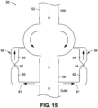
- FIG. 15 is a diagrammatic illustration of airflow through a positive displacement roots blower with venturi feedbacks, e.g., as previously described.
- positive displacement roots blowers may also include a cold air inlet, such as the cold air inlet 60 depicted in FIG. 16 and/or in U.S. Patent No. 10,851,788 .
- the cold air inlet can be used to reduce the temperature of air exiting the outlet 58. It will be appreciated that any other suitable cooling gas can be used rather than air.
- a positive displacement roots blower as described with reference to FIG. 16 may also include an air reservoir, such as the air reservoir 88 described with reference to FIG. 2 , proximate to the air inlet 52 to feed air into the pockets formed between adjacent lobes of respective rotors 54 and 56.
Landscapes
- Engineering & Computer Science (AREA)
- Mechanical Engineering (AREA)
- General Engineering & Computer Science (AREA)
- Chemical & Material Sciences (AREA)
- Combustion & Propulsion (AREA)
- Applications Or Details Of Rotary Compressors (AREA)
- Jet Pumps And Other Pumps (AREA)
Description
- Roots-type blowers, also referred to as roots blowers are positive displacement pumps that pump fluid through a pair of engaging rotors.
- A roots blower is one form of a positive displacement compressor that can be operated as an air compressor or as a vacuum pump. Roots blowers are easier to manufacturer than a screw compressor, less expensive, and more robust (tolerant) to the ingestion of debris that sometimes enters the compressor. Roots blowers find many applications in industry because they are oil-free compressors. Some of the applications for roots blowers are in the food processing industries, wastewater treatment plants, pumping dry goods into tanker trucks, and vacuum pumps used in street cleaners.
- One of the main problems with roots blowers is the noise they produce. A significant portion of the package size and cost are the silencers to make the operation of the blower acceptable in the workplace or in the community. Rapid opening of the trapped pocket at the discharge is the cause for these pulsations. Because the rotors are a two-dimensional profile extruded into the third dimension (aligned with the axis of rotation), the rotors open the trapped pocket instantaneously causing a sudden change in pressure at the discharge that is the noise source.
- It is an aim of the present invention to obviate or mitigate the aforementioned disadvantage with existing roots blowers.
- According to the invention there is provided a positive displacement roots blower according to claim 1, comprising:
- a housing having
- an inlet structured to receive an incoming flow of a compressible fluid,
- an outlet structured to exhaust an outgoing flow of the compressible fluid from the housing, and
- a venturi feedback, the venturi feedback connecting the outlet with a cavity within the housing, and having a venturi feedback inlet located between the inlet and the outlet,
- a pair of intermeshed rotating members supported for complementary rotation within the cavity of the housing, the rotating members and housing forming respective operating volumes there between which rotate with the rotating member;
- wherein the venturi feedback increases pressure inside the operating volumes prior to the rotating members discharging the outgoing fluid through the outlet.
- Each of the respective operating volumes may have the following regions:
open to the inlet/closed to the venturi feedback inlet/closed to the outlet; closed to the inlet/open to the venturi feedback inlet/closed to the outlet; and closed to the inlet/closed to the venturi feedback inlet/open to the outlet. - The venturi feedback inlet may be structured as an elongated entry to the respective volumes.
- The venturi feedback inlet may be positioned between about 100 degrees and 140 degrees from a 12 o'clock position.
- The region where the operating volume is closed to the inlet/open to the venturi feedback inlet/closed to the outlet may occur over an arc length of rotation of one of the intermeshed rotating members of at least 35 degrees.
- The region where the operating volume is closed to the inlet/open to the venturi feedback inlet/closed to the outlet may occur over an arc length of rotation of one of the intermeshed rotating members of at least 60 degrees.
- The operating volume may be at a pressure equal to a static pressure in the outlet as the operating volume transitions from the region where the operating volume is closed to the inlet/open to the venturi feedback inlet/closed to the outlet to the region closed to the inlet/closed to the venturi feedback inlet/open to the outlet.
- The housing may further include an air reservoir located proximate to the inlet for furnishing air to the operating volume.
- The volume of the air reservoir may be at least approximately equal to the volume of the operating volume to be filled.
- The volume of the air reservoir may be greater than the volume of the operating volume to be filled.
- This disclosure also relates to an apparatus comprising:
- a positive displacement roots blower having a pair of counter rotational rotors structured to be cooperatively engaged and interengagingly rotated, each of the pair of counter rotational rotors having a plurality of respective lobes;
- an inlet structured to provide a compressible fluid to an intake side of the positive displacement roots blower;
- an outlet positioned opposite the inlet and structured to discharge the compressible fluid; and
- a pair of feedback loops having respective feedback loop inlets into the positive displacement roots blower, and which are disposed on opposing sides of the positive displacement roots blower and structured to increase a pressure between operating volumes between the plurality of lobes;
- wherein each of the pair of counter rotational rotors includes a pressure equalization rotatable position in which adjacent lobes form a volume which is in fluid communication with a respective one of the pair of feedback loop inlets and in which the adjacent lobes are not in fluid communication with either of the inlet and the outlet.
- The feedback loops may comprise a convergent-divergent passage having a throat, the throat forming a restriction.
- The feedback loop inlets may be in the form of elongate openings in the positive displacement roots blower, the elongate openings in fluid communication with the volume when each of the pair of counter rotational rotors are in the pressure equalization position.
- The volume may be formed over an angular range of motion of the adjacent lobes of at least 45 degrees.
- The pressure equalization position of the adjacent lobes may form the volume open to the pressure relief passage when a trailing lobe of the adjacent lobes traverses an angle between 5 and 15 degrees after the inlet is closed.
- The positive displacement roots blower may further include a cooling air inlet disposed between the feedback loop inlet and the outlet, and wherein the pressure relief passage can be routed from a cooling air duct which feeds cooling air to the cooling air inlet.
- According to the invention there is provided a method of reducing pressure pulsation in a positive displacement roots blower according to claim 11, comprising:
- rotating a first rotor of a pair of intermeshed first and second rotors associated with the positive displacement roots blower, the positive displacement roots blower having a housing, an inlet, an outlet, and a passage connected to the outlet; and
- increasing the pressure of a volume created between adjacent lobes of the first rotor when the first rotor passes a venturi feedback loop inlet connected to the outlet, the inlet and the outlet blocked by the adjacent lobes when the volume is in communication with the venturi feedback loop inlet connected to the outlet.
- The method may further comprise rotating the first rotor through each of the following regions: open to the inlet/closed to the venturi feedback loop inlet/closed to the outlet; closed to the inlet/open to the venturi feedback loop inlet/closed to the outlet; and closed to the inlet/closed to the venturi feedback loop inlet/open to the outlet.
- The method may further comprise increasing the pressure of the volume created between adjacent lobes of the first rotor from atmospheric pressure when passing through the region open to the inlet/closed to the venturi feedback loop inlet/closed to the outlet to about 1 bar atm when reaching the region closed to the inlet/closed to the venturi feedback loop inlet/open to the outlet.
- The method may further comprise positioning the venturi feedback loop inlet between about 80 degrees and 140 degrees from a 12 o'clock position.
- The Detailed Description is described with reference to the accompanying figures. The use of the same reference numbers in different instances in the description and the figures may indicate similar or identical items.
-
FIG. 1 is a partial cross-sectional perspective view illustrating a positive displacement blower, with test points for a computational fluid dynamics (CFD) model for evaluating pressure overlayed on the blower. -
FIG. 2 is a partial cross-sectional perspective view illustrating a positive displacement roots blower having venturi feedbacks in accordance with examples of the present disclosure, where test points for a CFD model for evaluating pressure are overlayed on the roots blower. -
FIG. 3 is a graph illustrating mass flow in kilograms per second (kg/sec) versus angle in degrees showing a comparison of mass flow rates between the positive displacement blower illustrated inFIG. 1 and the positive displacement roots blower illustrated inFIG. 2 , respectively. -
FIG. 4 is a graph illustrating pocket pressure in bars versus angle in degrees showing a comparison of pocket pressures between the positive displacement blower illustrated inFIG. 1 and the positive displacement roots blower illustrated inFIG. 2 , respectively. -
FIG. 5 is a graph illustrating pressure pulsation in bars gage versus angle in degrees showing a comparison of inlet dynamic pressures at points P1_In' and P1_In for the positive displacement blower illustrated inFIG. 1 and the positive displacement roots blower illustrated inFIG. 2 , respectively. -
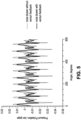
FIG. 6 is a graph illustrating pressure pulsation in bars gage versus angle in degrees showing a comparison of outlet dynamic pressures at points P1_Out' and P1_Out for the positive displacement blower illustrated inFIG. 1 and the positive displacement roots blower illustrated inFIG. 2 , respectively. -
FIG. 7 is a graph illustrating pressure pulsation in bars gage versus angle in degrees showing a comparison of outlet dynamic pressures at points P2_Out' and P2_Out for the positive displacement blower illustrated inFIG. 1 and the positive displacement roots blower illustrated inFIG. 2 , respectively. -
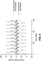
FIG. 8 is a graph illustrating pressure pulsation in bars gage versus angle in degrees showing a comparison of outlet dynamic pressures at points P3_Out' and P3_Out for the positive displacement blower illustrated inFIG. 1 and the positive displacement roots blower illustrated inFIG. 2 , respectively. -
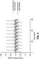
FIG. 9 is a graph illustrating pressure pulsation in bars gage versus angle in degrees showing a comparison of outlet dynamic pressures at points P4_Out' and P4_Out for the positive displacement blower illustrated inFIG. 1 and the positive displacement roots blower illustrated inFIG. 2 , respectively. -
FIG. 10A is a diagrammatic illustration of pressure inside a pocket of a positive displacement roots blower, such as the positive displacement roots blower illustrated inFIG. 2 , where a rotor is shown at an initial rotational orientation in accordance with examples of the present disclosure. -
FIG. 10B is a diagrammatic illustration of the pressure inside the pocket of the positive displacement roots blower ofFIG. 10A , where the rotor is shown at a rotational orientation ten degrees (10°) from the initial rotational orientation. -
FIG. 10C is a diagrammatic illustration of the pressure inside the pocket of the positive displacement roots blower ofFIG. 10A , where the rotor is shown at a rotational orientation twenty degrees (20°) from the initial rotational orientation. -
FIG. 10D is a diagrammatic illustration of the pressure inside the pocket of the positive displacement roots blower ofFIG. 10A , where the rotor is shown at a rotational orientation thirty degrees (30°) from the initial rotational orientation. -
FIG. 10E is a diagrammatic illustration of the pressure inside the pocket of the positive displacement roots blower ofFIG. 10A , where the rotor is shown at a rotational orientation forty degrees (40°) from the initial rotational orientation. -
FIG. 10F is a diagrammatic illustration of the pressure inside the pocket of the positive displacement roots blower ofFIG. 10A , where the rotor is shown at a rotational orientation fifty degrees (50°) from the initial rotational orientation. -
FIG. 10G is a diagrammatic illustration of the pressure inside the pocket of the positive displacement roots blower ofFIG. 10A , where the rotor is shown at a rotational orientation sixty degrees (60°) from the initial rotational orientation. -
FIG. 10H is a diagrammatic illustration of the pressure inside the pocket of the positive displacement roots blower ofFIG. 10A , where the rotor is shown at a rotational orientation seventy degrees (70°) from the initial rotational orientation. -
FIG. 11A is a side view illustrating a flow restricting geometry for a positive displacement roots blower, such as the positive displacement roots blower illustrated inFIG. 2 , in accordance with examples of the present disclosure. -
FIG. 11B is a side view illustrating another flow restricting geometry for a positive displacement roots blower, such as the positive displacement roots blower illustrated inFIG. 2 , in accordance with examples of the present disclosure. -
FIG. 11C is a side view illustrating a further flow restricting geometry for a positive displacement roots blower, such as the positive displacement roots blower illustrated inFIG. 2 , in accordance with examples of the present disclosure. -
FIG. 11D is a side view illustrating another flow restricting geometry for a positive displacement roots blower, such as the positive displacement roots blower illustrated inFIG. 2 , in accordance with examples of the present disclosure. -
FIG. 11E is a side view illustrating a further flow restricting geometry for a positive displacement roots blower, such as the positive displacement roots blower illustrated inFIG. 2 , in accordance with examples of the present disclosure. -
FIG. 11F is a side view illustrating another flow restricting geometry for a positive displacement roots blower, such as the positive displacement roots blower illustrated inFIG. 2 , in accordance with examples of the present disclosure. -
FIG. 11G is a side view illustrating a further flow restricting geometry for a positive displacement roots blower, such as the positive displacement roots blower illustrated inFIG. 2 , in accordance with examples of the present disclosure. -
FIG. 11H is a side view illustrating another flow restricting geometry for a positive displacement roots blower, such as the positive displacement roots blower illustrated inFIG. 2 , in accordance with examples of the present disclosure. -
FIG. 11J is a side view illustrating a further flow restricting geometry for a positive displacement roots blower, such as the positive displacement roots blower illustrated inFIG. 2 , in accordance with examples of the present disclosure. -
FIG. 11K is a side view illustrating another flow restricting geometry for a positive displacement roots blower, such as the positive displacement roots blower illustrated inFIG. 2 , in accordance with examples of the present disclosure. -
FIG. 12 is a perspective view illustrating a positive displacement roots blower, such as the positive displacement roots blower illustrated inFIG. 2 , in accordance with examples of the present disclosure. -
FIG. 13 is another perspective view of the positive displacement roots blower illustrated inFIG. 12 . -
FIG. 14 is a partial cross-sectional side elevation view of a positive displacement roots blower, such as the positive displacement roots blower illustrated inFIG. 2 , in accordance with examples of the present disclosure. -
FIG. 15 is a cross-sectional side view of a positive displacement roots blower, such as the positive displacement roots blower illustrated inFIG. 2 , where airflow through the roots blower is shown in accordance with examples of the present disclosure. -
FIG. 16 is a cross-sectional side view of another positive displacement roots blower with a cold air inlet, where airflow through the roots blower is shown in accordance with examples of the present disclosure. - For the purposes of promoting an understanding of the principles of the subject matter, reference will now be made to the examples illustrated in the drawings and specific language will be used to describe the same. It will nevertheless be understood that no limitation of the scope of the subject matter is thereby intended. Any alterations and further modifications in the described examples, and any further applications of the principles of the subject matter as described herein are contemplated as would normally occur to one skilled in the art to which the subject matter relates.
- As described herein, positive displacement roots blowers in accordance with the present disclosure reduce the pressure pulsations at the discharge of the positive displacement roots blowers. The systems, techniques, and apparatus of the present disclosure use one or more venturi feedback loops to raise the pocket pressure from inlet to the current discharge pressure. For example, the inlet pressure is less than the discharge pressure, and often the inlet pressure is at atmospheric pressure and the discharge pressure is near 1 bar gage.
- The systems, techniques, and apparatus herein can be described as a feedback loop created by the venturi from discharge to pocket. The feedback loop makes it possible for the pocket to equalize before opening completely to the discharge. This equalization process reduces pressure pulsations significantly.
- The pocket pressure is timed by the size of the venturi so that when the pocket closes at the inlet the venturi begins to raise the pocket pressure to equal the discharge pressure. When the pocket opens at the discharge, these two pressures are nearly the same and as a result the pressure pulsation is significantly reduced.
- The venturi typically is not in a sonic condition nor do the systems, techniques, and apparatus described herein necessarily operate the nozzle as a sonic nozzle. Instead, the venturi acts as a throttle to gradually let air into the pocket so the pressure does not suddenly change inside the pocket, defeating the purpose of reducing the pressure pulsations at the discharge.
- With reference to
FIG. 1 , a positivedisplacement roots blower 10 without a venturi feedback loop is illustrated having aninlet 12 structured to provide a fluid to a pair ofintermeshed rotors 14 and 16, forming a pocket of fluid, the joint rotation of which in turn delivers the fluid to theoutlet 18 for discharge from theblower 10. The pair ofintermeshed rotors 14 and 16 are located within ahousing 17. In some forms therotors 14 and 16 include a two-dimensional cross-sectional profile which is then extruded along a third dimension (aligned with the axis of rotation). Theroots blower 10 is structured to pull fluid from theinlet 12 and drive it toward theoutlet 18. - During a rotation sequence the
rotors 14 and 16 are structured to capture a pocket of fluid from theinlet 12 and rotate the pocket to a position to expose the pocket to theoutlet 18 to complete the process frominlet 12 tooutlet 18. The pocket is trapped between lobes of each respective rotor and a surface of the housing which encloses the rotors. The formation of pressure pulsations can occur at the discharge of the positive displacement roots blower. - Referring now to
FIGS. 2 through 16 , positive displacement roots blowers having one or more venturi feedback loops are described in accordance with examples of the present disclosure. In some examples, a positive displacement roots blower can be operated in a configuration where the inlet is at atmospheric pressure and the discharge is connected to a pressurized tank. In some examples, the roots blower can be operated in a configuration where the inlet is at less than atmospheric pressure (e.g., at vacuum pressure), and the discharge is at atmospheric pressure. As described, a discharge silencer may no longer be needed, and, if an operator wants a very quiet running machine, the size of the silencer may be reduced. In some examples, power may be increased by using a roots blower with one or more venturi feedback loops, e.g., by about 5% when compared to a roots blower without venturi feedback loops. The systems, techniques, and apparatus of the present disclosure may be particularly well suited to applications where noise and weight are critical factors. - As used herein, descriptions which refer to clock positions (e.g. "6 o'clock") will be understood to be a clock position relative to the
rotor 56 depicted inFIG. 2 , in which the rotor is rotating in the clockwise direction as viewed from the perspective ofFIG. 2 . It will be appreciated that therotor 54 rotates in a counter-clockwise direction, in which mirror images of the clock positions can be easily determined. The 12 o'clock position will be understood as the position determined by first drawing a reference line between theinlet side intersection 78 of the arc path swept by therotor 54 androtor 56 and theoutlet side intersection 80 of the arc path swept by therotor 54 androtor 56. A secondary line is then drawn orthogonal to the reference line which represents the 3 o'clock-9 o'clock clock axis. A clock reference line is then drawn orthogonal from the secondary line and offset from the reference line, in which the clock reference line is drawn to locate the top most and bottom most part of the arc that therotor 56 travels through. Although reference will be made herein to clock positions relative torotor 56, it will be understood that straightforward transformations can be made to determine appropriate clock positions of therotor 54. - In lieu of clock positions, reference may also be made herein using angular measurements. It will be appreciated that such angular measurements can either be absolute or relative measurements depending on the context, where the absolute angular measurements are referenced starting from the 12 o'clock positioned as determined above and which progresses in a clockwise direction. To set forth just a few non-limiting examples, 12 o'clock is the same as 0 degrees; 3 o'clock is the same as 90 degrees; 6 o'clock is the same as 180 degrees, etc.
- The
roots blower 50 has aninlet 52 and anoutlet 58, e.g., as described with reference toFIG. 2 . Therotors outlet 58. The accumulation of air continuously added at the outlet increases the discharge pressure. The trapped pocket created by the opening and closing of the rotors is typically at atmospheric pressure. However, with a positive displacement machine, the built-in pressure ratio is the main factor used to determine how much change in pressure the blower will produce. The change in pressure is the difference between discharge and inlet. Though the illustrated example depictsrespective rotors -
FIG. 2 shows twoventuri feedbacks 68, one on either side of the blower that feed air from theoutlet 58 to the pocket. The venturi feedbacks 68 connect theoutlet 58 of theroots blower 50 to thehousing 57 surrounding therotors venturi feedback inlet 72. In accordance with present examples, theventuri feedback 68 may connect the discharge at around the 4 o'clock position of thehousing 57, but other starting positions are contemplated herein. Additionally, in some examples there is anair reservoir 88 positioned proximate to the blower inlet. Since the pocket has little time for air to feed into the pocket as therotors air reservoir 88 is available when the pocket opens. In examples of the disclosure, the size and dimension of theair reservoir 88 may be equal to or greater than the pocket that will open and be filled. Both features can provide a reduction in the pressure pulsations. - A venturi as described herein is a tube having a venturi ingress for incoming flow, a venturi egress for outgoing flow, and a tapering, constricted section between the venturi ingress and the venturi egress, where there is a smooth transition between the venturi ingress and the constricted section and between the constricted section and the venturi egress. The constricted section of the venturi may be positioned at a midpoint between the venturi ingress and the venturi egress or may be closer to one of the venturi ingress or the venturi egress. The tube forming the venturi has a first cross-sectional area (e.g., as a function of diameter for a circular tube) at the venturi ingress, a second cross-sectional area (e.g., as a function of diameter for a circular tube) at the constricted section, and a third cross-sectional area (e.g., as function of diameter for a circular tube) at the venturi egress, where the second cross-sectional area or tube diameter at the constricted section is smaller than the first and third cross-sectional areas or tube diameters at the venturi ingress and the venturi egress respectively. The first tube cross-sectional area or diameter at the venturi inlet may be smaller than, equal to, or greater than the third tube cross-sectional area or diameter at the venturi egress. However, the second tube cross-sectional area or diameter is smaller than the first and third cross-sectional areas or tube diameters. A venturi works on the principle of the Venturi Effect, which corresponds to the reduction in fluid pressure that results when the fluid flows through the constricted section of the tube. As the pressure of the fluid passing through the constricted section decreases, its velocity increases. As the flow leaves the constricted section of the tube, the velocity of the flow decreases as its pressure increases once again. A venturi tube may include more than one constricted section for restricting the flow of the fluid passing through the venturi feedback.
-
Fig. 2 shows venturi feedbacks 68 having aventuri ingress 82, a constrictedsection 84, and aventuri egress 86.Venturi ingress 82 is connected tooutlet 58 through a connectingtube 81.Venturi egress 86 is connected to the inside of thehousing 57 throughventuri inlet 72. - Referring now to
FIG. 3 , the mass flow rate for a roots blower without a venturi feedback loop is compared to the mass flow rate for a roots blower with venturi feedback loops as described herein. As shown, the mass flow rate of the roots blower without the venturi feedback loop has both a positive and a negative flow direction, while the roots blower with the venturi feedback loop as described herein discharges air consistently in one direction. Additionally, the peak-to-peak amplitudes of the mass flow rate of the roots blower without the venturi feedback loop are extreme when compared to the amplitudes of the roots blower with the venturi feedback loop. The venturi feedback(s) make a significant difference in how the compressor operates. The positive displacement roots blowers with venturi feedback loops as described herein can run smoothly with a steady air output streaming out at a uniform rate. In contrast, the roots blower without the venturi feedback loop sucks and blows air with each rotation of the rotors, increasing the noise and pressure pulsations of the system. Finally,FIG. 3 show that the average mass flow rate of the two designs is not necessarily affected by the addition of the venturi feedback loop. - With reference to
FIG. 4 , pocket pressure during rotation is described. Different stages of pocket pressure as a pocket is opened, closed, and then discharged are shown. The dashed line shows the pocket pressure of a roots blower without a venturi feedback loop. The pressure in the pocket remains at the inlet pressure until the pocket is opened to the higher discharge pressure. The process of opening causes the pocket pressure to rapidly increase, which is the cause for the pressure pulsation in a roots blower without a venturi feedback loop. The solid line shows the pressure in the pocket of the roots blower with a venturi feedback loop as described herein. As shown, p1 shows a pressure when the pocket is open to the atmosphere. The venturi feedback loop gradually increases the pocket pressure as the pocket rotates frominlet 52 tooutlet 58, until it nearly equals with the discharge pressure. In the accompanying graph, point p2 shows an intermediate pressure as the pocket rotates frominlet 52 tooutlet 58. Finally, point p3 shows the pressure fluctuations inside the pocket as it opens to theoutlet 58. The closer the pressure of the pocket is to the discharge pressure prior to opening to the outlet, the lower the pressure pulsation is at the discharge of the compressor. - Referring again to
FIG. 2 , the locations of measurement points for a computational fluid dynamics (CFD) analysis of the positive displacement roots blower with venturi feedback are shown. With reference toFIG. 1 , the locations of measurement points for a CFD analysis of the positive displacement roots blower without venturi feedback are shown. As shown inFIG. 5 , the pressure pulsation at point P1_In of the inlet of the roots blower ofFIG. 2 is shown, compared to the pressure pulsation at P1_In' of the roots blower ofFIG. 1 . The pressure pulsations at the inlet of the roots blower ofFIG. 2 are initially reduced by the presence of theair reservoir 88. This is because theair reservoir 88 adds fluid capacity where needed, so that the air flowing into the roots blower is no longer vacuumed into the inlet as in the roots blower ofFIG. 1 . - Referring to
FIGS. 6 through 9 , the pressure pulsations at the outlets of the roots blower with the venturi feedback are shown at points P1_Out, P2_Out, P3_Out, and P4_Out compared respectively with points P1_Out', P2_Out', P3_Out', and P4_Out' of the roots blower without the venturi feedback. In these cases, the pressure pulsations, measured in bars, are decreased significantly in the roots blower with the venturi feedback, with the lowest levels of pulsation near point P4_Out of the discharge of the compressor where a silencer (not shown) may typically be positioned. - Turning now to
FIGS. 10A-10H , computational results are shown comparing the pressure inside the pockets at different orientations of the of lobes as therotors FIG. 1 rotate, starting at a relative angle of 0 degrees of the rotors inFIG. 10A and progressing in 10 degree increments throughout the remainder ofFIGS. 10B-10H . The angle measurements shown inFIGS. 10A-10H are for convenience of illustration and do not correspond precisely to the measurements provided herein with respect to location of inlets and outlets as will be understood in the context of the description. In other words, 0 degrees inFIG. 10A does not necessarily correspond to the 12 o'clock position described above. - The 0 degrees indication in
FIG. 10A illustrates a position in which therotor 56 is about to sweep past theinlet 52 and thereby close off and form a pocket between adjacent lobes of the rotor 56 (as shown inFIG. 10C ) which will be moved to theoutlet 58 upon further rotation of therotor 56. Once the pocket is rotated to theoutlet 58 any residual gas within the pocket can be vented, before therotor 56 is rotated into intermeshed engagement withrotor 54 and the process begins anew.FIG. 10F showsrotor 54 venting the residual gas within the pocket to theoutlet 58. It will be appreciated that the pressure in the pocket is lower than pressure of a gas at theoutlet 58 in some modes of operation, while in other modes of operation, the pocket can be at a similar pressure to pressure of gas at the outlet at the moment of venting. - As will be appreciated given the discussion above, the
rotors inlet 52, venturi feedbacks 68, andoutlet 58. Region (1) can be characterized by the pocket being open toinlet 52, closed to venturifeedback inlet 72, and closed tooutlet 58. Region (2) can be characterized by the pocket being closed toinlet 52, open to theventuri feedback inlet 72, and closed tooutlet 58. Region (3) can be characterized as the pocket being closed toinlet 52, closed to venturifeedback inlet 72, and open tooutlet 58. - The arc length of travel associated with the
rotors venturi feedback 68 increases the pressure of the pocket, and where over that arc length the pocket is sealed from theinlet 52 and theoutlet 58 by virtue of the position of the rotor within the volume (e.g. Region (2)) can be about 35 degrees in some examples, while in other examples it can be about 40, 45, 50, 55, 60, 65, 70, and 75 degrees, and in some examples can be up to about 90 degrees. For example, different arc lengths of travel are contemplated depending on whether therotor 56 is a three lobed or four lobed rotor (or possibly a rotor having other numbers of lobes). It will be appreciated that the term "sealed" as used in this context includes those situations in which the rotor may not be perfectly contacted along the entirely of the surface and instead may include a lift or other imperfection of contact that permits a small to negligible amount of gas to leak past. It can of course also include those circumstances in which a perfect fluid tight seal is formed. - The location of the upstream edge of the
venturi inlet 72 of theventuri feedback 68 into the pocket can be anywhere between at least 60 degrees and at least 120 degrees from the 12 o'clock position, and in some examples can be greater than 120 degrees. In some examples, theventuri inlet 72 can be positioned to higher angles up to 170 degrees. To set forth just a few nonlimiting example, the angular position range between about 90, 95, 100, 105, 110, 115, 120, 125, 130, 135, 140, 145, and 150 degrees and about 90, 95, 100, 105, 110, 115, 120, 125, 130, 135, 140, 145, and 150 degrees. - In some examples, the
venturi feedback inlet 72 is structured as an elongated entry to the respective pockets contained between therotors housing 57, and theventuri inlet 72 may be positioned between about 100 degrees and about 140 degrees from a 12 o'clock position. - In some examples, region (2) may occur over an arc length of rotation of one of the intermeshed rotating members of at least 35 degrees. In examples of the present application, region (2) could occur over an arc length of rotation of one of the intermeshed rotating members of at least 60 degrees.
- It will be appreciated that while hourglass-shaped cross-sectional area restriction venturi feedbacks have been described above and shown in the accompanying figures with some specificity, other shapes of cross-sectional area restrictions can be used with positive displacement roots blower devices in accordance with examples of the present disclosure. These shapes can include but are not necessarily limited to shapes as shown in
FIGS. 11A-11H and11J-11K . Additionally, a mechanical valve may be used in place of a cross-sectional area restriction as a flow restricting device. In some examples, one or more of the passages connecting the operating volumes to the restriction can be connected to a pressure of the outlet. In examples, one or more of the passages connecting the operating volumes to the restriction can be connected to an external pressure (e.g., atmospheric pressure). - Referring to
FIGS. 12 through 14 , ahousing 57 for a positive displacement roots blower that includes venturi feedback loops is shown in accordance with examples of the present disclosure.Housing 57 includesventuri housing 70, which contains theventuri feedback 68 between theoutlet 58 and the inner surface ofhousing 57. Theventuri feedback 68 is shown in the cross-sectional view ofhousing 57 inFIG. 14 . The fluid flows from right to left, entering atinlet 52 and flowing radially withinhousing 57 after being received between the respective lobes ofrotors outlet 58 and partially flowing throughventuri feedback 68.FIG. 15 is a diagrammatic illustration of airflow through a positive displacement roots blower with venturi feedbacks, e.g., as previously described. - Some examples of positive displacement roots blowers that include venturi feedback loops may also include a cold air inlet, such as the
cold air inlet 60 depicted inFIG. 16 and/or inU.S. Patent No. 10,851,788 outlet 58. It will be appreciated that any other suitable cooling gas can be used rather than air. In some examples, a positive displacement roots blower as described with reference toFIG. 16 may also include an air reservoir, such as theair reservoir 88 described with reference toFIG. 2 , proximate to theair inlet 52 to feed air into the pockets formed between adjacent lobes ofrespective rotors
Claims (14)
- A positive displacement roots blower comprising:
a housing (57) havingan inlet (52) structured to receive an incoming flow of a compressible fluid,an outlet (58) structured to exhaust an outgoing flow of the compressible fluid from the housing (57),a pair of intermeshed rotating members (54,56) supported for complementary rotation within a cavity of the housing (57) located between the inlet (52) and the outlet (58), the rotating members and housing forming respective operating volumes there between which rotate with the rotating member; anda venturi feedback (68), the venturi feedback connecting the outlet (58) with the cavity within the housing (57), and having a venturi feedback inlet (72) opening into the cavity between the inlet (52) and the outlet (58), such that the venturi feedback increases pressure inside the operating volumes prior to the rotating members (54,56) discharging the outgoing fluid through the outlet (58). - The positive displacement roots blower of claim 1, wherein each of the respective operating volumes have the following regions: open to the inlet (52)/closed to the venturi feedback inlet (72)/closed to the outlet (58); closed to the inlet/open to the venturi feedback inlet/closed to the outlet; and closed to the inlet/closed to the venturi feedback inlet/open to the outlet.
- The positive displacement roots blower of claim 1, wherein the venturi feedback inlet (72) is structured as an elongated entry to the respective volumes.
- The positive displacement roots blower of claim 3, wherein the venturi feedback inlet (72) is positioned between about 100 degrees and 140 degrees from a 12 o'clock position.
- The positive displacement roots blower of claim 4, wherein the region where the operating volume is closed to the inlet (52)/open to the venturi feedback inlet (72)/closed to the outlet (58) occurs over an arc length of rotation of one of the intermeshed rotating members (54,56) of at least 35 degrees.
- The positive displacement roots blower of claim 5, wherein the region where the operating volume is closed to the inlet (52)/open to the venturi feedback inlet (72)/closed to the outlet (58) occurs over an arc length of rotation of one of the intermeshed rotating members (54,56) of at least 60 degrees.
- The positive displacement roots blower of claim 5, wherein the operating volume is at a pressure equal to a static pressure in the outlet (58) as the operating volume transitions from the region where the operating volume is closed to the inlet (52)/open to the venturi feedback inlet (72)/closed to the outlet (58) to the region closed to the inlet/closed to the venturi feedback inlet/open to the outlet.
- The positive displacement roots blower of claim 1, wherein the housing (57) further includes an air reservoir (88) located proximate to the inlet (52) for furnishing air to the operating volume.
- The positive displacement roots blower of claim 8, wherein the volume of the air reservoir (88) is at least approximately equal to the volume of the operating volume to be filled.
- The positive displacement roots blower of claim 8, wherein the volume of the air reservoir (88) is greater than the volume of the operating volume to be filled.
- A method of reducing pressure pulsation in a positive displacement roots blower comprising:rotating a first rotor (54) of a pair of intermeshed first and second rotors (54,56) supported for complementary rotation within a cavity of a housing (57) of the positive displacement roots blower, the positive displacement roots blower having an inlet (52) upstream of the cavity, an outlet (58) downstream of the cavity, and a venturi feedback (68) connected to the outlet (58), the venturi feedback having a venturi feedback inlet (72) opening into the cavity;increasing the pressure of a volume created between adjacent lobes of the first rotor when the first rotor passes the venturi feedback inlet (72), the inlet (52) and the outlet (58) blocked by the adjacent lobes when the volume is in communication with the venturi feedback inlet (72).
- The method of claim 11, comprising rotating the first rotor through each of the following regions: open to the inlet (52)/closed to the venturi feedback inlet (72)/closed to the outlet (58); closed to the inlet/open to the venturi feedback inlet/closed to the outlet; and closed to the inlet/closed to the venturi feedback inlet/open to the outlet.
- The method of claim 11, further comprising increasing the pressure of the volume created between adjacent lobes of the first rotor from atmospheric pressure when passing through the region open to the inlet (52)/closed to the venturi feedback inlet (72)/closed to the outlet (58) to about 1 bar atm when reaching the region closed to the inlet/closed to the venturi feedback inlet/open to the outlet.
- The method of claim 11, further comprising positioning the venturi feedback inlet (72) between about 80 degrees and 140 degrees from a 12 o'clock position.
Applications Claiming Priority (1)
| Application Number | Priority Date | Filing Date | Title |
|---|---|---|---|
| US202063112981P | 2020-11-12 | 2020-11-12 |
Publications (3)
| Publication Number | Publication Date |
|---|---|
| EP4001651A2 EP4001651A2 (en) | 2022-05-25 |
| EP4001651A3 EP4001651A3 (en) | 2022-07-06 |
| EP4001651B1 true EP4001651B1 (en) | 2024-05-08 |
Family
ID=78617326
Family Applications (1)
| Application Number | Title | Priority Date | Filing Date |
|---|---|---|---|
| EP21208039.4A Active EP4001651B1 (en) | 2020-11-12 | 2021-11-12 | Positive displacement roots blower noise suppression |
Country Status (2)
| Country | Link |
|---|---|
| US (2) | US12060881B2 (en) |
| EP (1) | EP4001651B1 (en) |
Families Citing this family (1)
| Publication number | Priority date | Publication date | Assignee | Title |
|---|---|---|---|---|
| EP4001651B1 (en) * | 2020-11-12 | 2024-05-08 | Ingersoll-Rand Industrial U.S., Inc. | Positive displacement roots blower noise suppression |
Family Cites Families (16)
| Publication number | Priority date | Publication date | Assignee | Title |
|---|---|---|---|---|
| US2489887A (en) * | 1946-07-11 | 1949-11-29 | Roots Connersville Blower Corp | Rotary pump |
| FR1121079A (en) | 1955-02-03 | 1956-07-20 | Volumetric turbine | |
| US4215977A (en) * | 1977-11-14 | 1980-08-05 | Calspan Corporation | Pulse-free blower |
| US4185664A (en) | 1978-04-17 | 1980-01-29 | Dresser Industries, Inc. | Low noise fluid pressure reducer |
| US5090879A (en) * | 1989-06-20 | 1992-02-25 | Weinbrecht John F | Recirculating rotary gas compressor |
| US5702240A (en) | 1995-05-05 | 1997-12-30 | Tuthill Corporation | Rotary positive displacement blower having a diverging outlet part |
| US6099277A (en) * | 1998-08-12 | 2000-08-08 | Dresser Industries, Inc. | Gas blower and method utilizing recirculation openings |
| US6312240B1 (en) * | 1999-05-28 | 2001-11-06 | John F. Weinbrecht | Reflux gas compressor |
| US6203297B1 (en) * | 1999-09-29 | 2001-03-20 | Dresser Equipment Group, Inc. | Fluid flow device with improved cooling system and method for cooling a vacuum pump |
| EP1286053A1 (en) * | 2001-08-21 | 2003-02-26 | Ford Global Technologies, Inc., A subsidiary of Ford Motor Company | Rotary pump with backflow |
| US20120195783A1 (en) * | 2010-01-22 | 2012-08-02 | Fitzpatrick Erich R | Noise and shock reduction in rotary positive displacement blowers |
| US9151292B2 (en) | 2011-01-05 | 2015-10-06 | Hi-Bar Blowers, Inc. | Screw compressor with a shunt pulsation trap |
| US9732754B2 (en) | 2011-06-07 | 2017-08-15 | Hi-Bar Blowers, Inc. | Shunt pulsation trap for positive-displacement machinery |
| US10316737B2 (en) * | 2014-04-30 | 2019-06-11 | Edward Charles Mendler, III | Supercharger cooling means |
| US10851788B2 (en) | 2018-12-20 | 2020-12-01 | Ingersoll-Rand Industrial U.S., Inc. | Vacuum pump with noise attenuating passage |
| EP4001651B1 (en) * | 2020-11-12 | 2024-05-08 | Ingersoll-Rand Industrial U.S., Inc. | Positive displacement roots blower noise suppression |
-
2021
- 2021-11-12 EP EP21208039.4A patent/EP4001651B1/en active Active
- 2021-11-12 US US17/525,133 patent/US12060881B2/en active Active
-
2024
- 2024-07-24 US US18/782,891 patent/US12624693B2/en active Active
Also Published As
| Publication number | Publication date |
|---|---|
| US12060881B2 (en) | 2024-08-13 |
| EP4001651A2 (en) | 2022-05-25 |
| US12624693B2 (en) | 2026-05-12 |
| EP4001651A3 (en) | 2022-07-06 |
| US20240384718A1 (en) | 2024-11-21 |
| US20220145885A1 (en) | 2022-05-12 |
Similar Documents
| Publication | Publication Date | Title |
|---|---|---|
| KR100876318B1 (en) | Operation method of vacuum exhaust device and vacuum exhaust device | |
| CN104632618B (en) | Roots-type wind turbine with leakage mechanism | |
| KR100730073B1 (en) | Evacuating apparatus | |
| US20050118035A1 (en) | Multistage dry vacuum pump | |
| US12624693B2 (en) | Positive displacement roots blower noise suppression | |
| US5702240A (en) | Rotary positive displacement blower having a diverging outlet part | |
| KR102026276B1 (en) | Flow volume measurement device for turbo compressor, and turbo compressor | |
| US20160356273A1 (en) | Vacuum pump system with light gas pumping and leak detection apparatus comprising the same | |
| KR20120112736A (en) | Pump | |
| JPH05272478A (en) | Vacuum pump | |
| US10851788B2 (en) | Vacuum pump with noise attenuating passage | |
| US10280923B2 (en) | Suction/compression assembly for a waste material aspiration system | |
| WO2023040643A1 (en) | Compressor | |
| CN110475972B (en) | Scroll fluid machine having a plurality of scroll members | |
| CN108138773A (en) | For collecting the positive displacement blade compressor of the equipment of waste materials | |
| JP2008088879A (en) | Evacuation apparatus | |
| CN1042851C (en) | rotary compressor | |
| TWI503483B (en) | Oil rotary vacuum pump | |
| US11946480B2 (en) | Centrifugal compressor | |
| CN115274504A (en) | Gas delivery box of semiconductor equipment and semiconductor equipment | |
| JP5393577B2 (en) | Dry vacuum pump device and exhaust unit | |
| TW202314120A (en) | Screw-type vacuum pump | |
| JP6653732B2 (en) | Vacuum pump unit | |
| CN113710884B (en) | Variable capacity turbines and superchargers | |
| JP3606637B2 (en) | Fluid machinery with variable guide vanes |
Legal Events
| Date | Code | Title | Description |
|---|---|---|---|
| PUAI | Public reference made under article 153(3) epc to a published international application that has entered the european phase |
Free format text: ORIGINAL CODE: 0009012 |
|
| STAA | Information on the status of an ep patent application or granted ep patent |
Free format text: STATUS: THE APPLICATION HAS BEEN PUBLISHED |
|
| AK | Designated contracting states |
Kind code of ref document: A2 Designated state(s): AL AT BE BG CH CY CZ DE DK EE ES FI FR GB GR HR HU IE IS IT LI LT LU LV MC MK MT NL NO PL PT RO RS SE SI SK SM TR |
|
| PUAL | Search report despatched |
Free format text: ORIGINAL CODE: 0009013 |
|
| AK | Designated contracting states |
Kind code of ref document: A3 Designated state(s): AL AT BE BG CH CY CZ DE DK EE ES FI FR GB GR HR HU IE IS IT LI LT LU LV MC MK MT NL NO PL PT RO RS SE SI SK SM TR |
|
| RIC1 | Information provided on ipc code assigned before grant |
Ipc: F04C 29/06 20060101ALI20220527BHEP Ipc: F04C 29/00 20060101ALI20220527BHEP Ipc: F04C 29/12 20060101ALI20220527BHEP Ipc: F04C 18/12 20060101AFI20220527BHEP |
|
| STAA | Information on the status of an ep patent application or granted ep patent |
Free format text: STATUS: REQUEST FOR EXAMINATION WAS MADE |
|
| 17P | Request for examination filed |
Effective date: 20221223 |
|
| RBV | Designated contracting states (corrected) |
Designated state(s): AL AT BE BG CH CY CZ DE DK EE ES FI FR GB GR HR HU IE IS IT LI LT LU LV MC MK MT NL NO PL PT RO RS SE SI SK SM TR |
|
| GRAP | Despatch of communication of intention to grant a patent |
Free format text: ORIGINAL CODE: EPIDOSNIGR1 |
|
| STAA | Information on the status of an ep patent application or granted ep patent |
Free format text: STATUS: GRANT OF PATENT IS INTENDED |
|
| RIC1 | Information provided on ipc code assigned before grant |
Ipc: F04C 29/06 20060101ALI20231121BHEP Ipc: F04C 29/00 20060101ALI20231121BHEP Ipc: F04C 29/12 20060101ALI20231121BHEP Ipc: F04C 18/12 20060101AFI20231121BHEP |
|
| INTG | Intention to grant announced |
Effective date: 20231220 |
|
| GRAS | Grant fee paid |
Free format text: ORIGINAL CODE: EPIDOSNIGR3 |
|
| GRAA | (expected) grant |
Free format text: ORIGINAL CODE: 0009210 |
|
| STAA | Information on the status of an ep patent application or granted ep patent |
Free format text: STATUS: THE PATENT HAS BEEN GRANTED |
|
| AK | Designated contracting states |
Kind code of ref document: B1 Designated state(s): AL AT BE BG CH CY CZ DE DK EE ES FI FR GB GR HR HU IE IS IT LI LT LU LV MC MK MT NL NO PL PT RO RS SE SI SK SM TR |
|
| REG | Reference to a national code |
Ref country code: GB Ref legal event code: FG4D |
|
| REG | Reference to a national code |
Ref country code: CH Ref legal event code: EP |
|
| REG | Reference to a national code |
Ref country code: DE Ref legal event code: R096 Ref document number: 602021013006 Country of ref document: DE |
|
| REG | Reference to a national code |
Ref country code: IE Ref legal event code: FG4D |
|
| REG | Reference to a national code |
Ref country code: LT Ref legal event code: MG9D |
|
| RAP4 | Party data changed (patent owner data changed or rights of a patent transferred) |
Owner name: INGERSOLL-RAND INDUSTRIAL U.S., INC. |
|
| REG | Reference to a national code |
Ref country code: NL Ref legal event code: MP Effective date: 20240508 |
|
| PG25 | Lapsed in a contracting state [announced via postgrant information from national office to epo] |
Ref country code: IS Free format text: LAPSE BECAUSE OF FAILURE TO SUBMIT A TRANSLATION OF THE DESCRIPTION OR TO PAY THE FEE WITHIN THE PRESCRIBED TIME-LIMIT Effective date: 20240908 |
|
| PG25 | Lapsed in a contracting state [announced via postgrant information from national office to epo] |
Ref country code: BG Free format text: LAPSE BECAUSE OF FAILURE TO SUBMIT A TRANSLATION OF THE DESCRIPTION OR TO PAY THE FEE WITHIN THE PRESCRIBED TIME-LIMIT Effective date: 20240508 |
|
| PG25 | Lapsed in a contracting state [announced via postgrant information from national office to epo] |
Ref country code: FI Free format text: LAPSE BECAUSE OF FAILURE TO SUBMIT A TRANSLATION OF THE DESCRIPTION OR TO PAY THE FEE WITHIN THE PRESCRIBED TIME-LIMIT Effective date: 20240508 Ref country code: HR Free format text: LAPSE BECAUSE OF FAILURE TO SUBMIT A TRANSLATION OF THE DESCRIPTION OR TO PAY THE FEE WITHIN THE PRESCRIBED TIME-LIMIT Effective date: 20240508 |
|
| PG25 | Lapsed in a contracting state [announced via postgrant information from national office to epo] |
Ref country code: GR Free format text: LAPSE BECAUSE OF FAILURE TO SUBMIT A TRANSLATION OF THE DESCRIPTION OR TO PAY THE FEE WITHIN THE PRESCRIBED TIME-LIMIT Effective date: 20240809 |
|
| PG25 | Lapsed in a contracting state [announced via postgrant information from national office to epo] |
Ref country code: PT Free format text: LAPSE BECAUSE OF FAILURE TO SUBMIT A TRANSLATION OF THE DESCRIPTION OR TO PAY THE FEE WITHIN THE PRESCRIBED TIME-LIMIT Effective date: 20240909 |
|
| REG | Reference to a national code |
Ref country code: AT Ref legal event code: MK05 Ref document number: 1685201 Country of ref document: AT Kind code of ref document: T Effective date: 20240508 |
|
| PG25 | Lapsed in a contracting state [announced via postgrant information from national office to epo] |
Ref country code: NL Free format text: LAPSE BECAUSE OF FAILURE TO SUBMIT A TRANSLATION OF THE DESCRIPTION OR TO PAY THE FEE WITHIN THE PRESCRIBED TIME-LIMIT Effective date: 20240508 |
|
| PG25 | Lapsed in a contracting state [announced via postgrant information from national office to epo] |
Ref country code: ES Free format text: LAPSE BECAUSE OF FAILURE TO SUBMIT A TRANSLATION OF THE DESCRIPTION OR TO PAY THE FEE WITHIN THE PRESCRIBED TIME-LIMIT Effective date: 20240508 |
|
| PG25 | Lapsed in a contracting state [announced via postgrant information from national office to epo] |
Ref country code: AT Free format text: LAPSE BECAUSE OF FAILURE TO SUBMIT A TRANSLATION OF THE DESCRIPTION OR TO PAY THE FEE WITHIN THE PRESCRIBED TIME-LIMIT Effective date: 20240508 |
|
| PG25 | Lapsed in a contracting state [announced via postgrant information from national office to epo] |
Ref country code: PL Free format text: LAPSE BECAUSE OF FAILURE TO SUBMIT A TRANSLATION OF THE DESCRIPTION OR TO PAY THE FEE WITHIN THE PRESCRIBED TIME-LIMIT Effective date: 20240508 |
|
| PG25 | Lapsed in a contracting state [announced via postgrant information from national office to epo] |
Ref country code: LV Free format text: LAPSE BECAUSE OF FAILURE TO SUBMIT A TRANSLATION OF THE DESCRIPTION OR TO PAY THE FEE WITHIN THE PRESCRIBED TIME-LIMIT Effective date: 20240508 |
|
| PG25 | Lapsed in a contracting state [announced via postgrant information from national office to epo] |
Ref country code: PT Free format text: LAPSE BECAUSE OF FAILURE TO SUBMIT A TRANSLATION OF THE DESCRIPTION OR TO PAY THE FEE WITHIN THE PRESCRIBED TIME-LIMIT Effective date: 20240909 Ref country code: PL Free format text: LAPSE BECAUSE OF FAILURE TO SUBMIT A TRANSLATION OF THE DESCRIPTION OR TO PAY THE FEE WITHIN THE PRESCRIBED TIME-LIMIT Effective date: 20240508 Ref country code: NO Free format text: LAPSE BECAUSE OF FAILURE TO SUBMIT A TRANSLATION OF THE DESCRIPTION OR TO PAY THE FEE WITHIN THE PRESCRIBED TIME-LIMIT Effective date: 20240808 Ref country code: NL Free format text: LAPSE BECAUSE OF FAILURE TO SUBMIT A TRANSLATION OF THE DESCRIPTION OR TO PAY THE FEE WITHIN THE PRESCRIBED TIME-LIMIT Effective date: 20240508 Ref country code: LV Free format text: LAPSE BECAUSE OF FAILURE TO SUBMIT A TRANSLATION OF THE DESCRIPTION OR TO PAY THE FEE WITHIN THE PRESCRIBED TIME-LIMIT Effective date: 20240508 Ref country code: IS Free format text: LAPSE BECAUSE OF FAILURE TO SUBMIT A TRANSLATION OF THE DESCRIPTION OR TO PAY THE FEE WITHIN THE PRESCRIBED TIME-LIMIT Effective date: 20240908 Ref country code: HR Free format text: LAPSE BECAUSE OF FAILURE TO SUBMIT A TRANSLATION OF THE DESCRIPTION OR TO PAY THE FEE WITHIN THE PRESCRIBED TIME-LIMIT Effective date: 20240508 Ref country code: GR Free format text: LAPSE BECAUSE OF FAILURE TO SUBMIT A TRANSLATION OF THE DESCRIPTION OR TO PAY THE FEE WITHIN THE PRESCRIBED TIME-LIMIT Effective date: 20240809 Ref country code: FI Free format text: LAPSE BECAUSE OF FAILURE TO SUBMIT A TRANSLATION OF THE DESCRIPTION OR TO PAY THE FEE WITHIN THE PRESCRIBED TIME-LIMIT Effective date: 20240508 Ref country code: ES Free format text: LAPSE BECAUSE OF FAILURE TO SUBMIT A TRANSLATION OF THE DESCRIPTION OR TO PAY THE FEE WITHIN THE PRESCRIBED TIME-LIMIT Effective date: 20240508 Ref country code: BG Free format text: LAPSE BECAUSE OF FAILURE TO SUBMIT A TRANSLATION OF THE DESCRIPTION OR TO PAY THE FEE WITHIN THE PRESCRIBED TIME-LIMIT Effective date: 20240508 Ref country code: AT Free format text: LAPSE BECAUSE OF FAILURE TO SUBMIT A TRANSLATION OF THE DESCRIPTION OR TO PAY THE FEE WITHIN THE PRESCRIBED TIME-LIMIT Effective date: 20240508 Ref country code: RS Free format text: LAPSE BECAUSE OF FAILURE TO SUBMIT A TRANSLATION OF THE DESCRIPTION OR TO PAY THE FEE WITHIN THE PRESCRIBED TIME-LIMIT Effective date: 20240808 |
|
| PG25 | Lapsed in a contracting state [announced via postgrant information from national office to epo] |
Ref country code: DK Free format text: LAPSE BECAUSE OF FAILURE TO SUBMIT A TRANSLATION OF THE DESCRIPTION OR TO PAY THE FEE WITHIN THE PRESCRIBED TIME-LIMIT Effective date: 20240508 |
|
| PG25 | Lapsed in a contracting state [announced via postgrant information from national office to epo] |
Ref country code: EE Free format text: LAPSE BECAUSE OF FAILURE TO SUBMIT A TRANSLATION OF THE DESCRIPTION OR TO PAY THE FEE WITHIN THE PRESCRIBED TIME-LIMIT Effective date: 20240508 |
|
| PG25 | Lapsed in a contracting state [announced via postgrant information from national office to epo] |
Ref country code: CZ Free format text: LAPSE BECAUSE OF FAILURE TO SUBMIT A TRANSLATION OF THE DESCRIPTION OR TO PAY THE FEE WITHIN THE PRESCRIBED TIME-LIMIT Effective date: 20240508 |
|
| PG25 | Lapsed in a contracting state [announced via postgrant information from national office to epo] |
Ref country code: SK Free format text: LAPSE BECAUSE OF FAILURE TO SUBMIT A TRANSLATION OF THE DESCRIPTION OR TO PAY THE FEE WITHIN THE PRESCRIBED TIME-LIMIT Effective date: 20240508 Ref country code: RO Free format text: LAPSE BECAUSE OF FAILURE TO SUBMIT A TRANSLATION OF THE DESCRIPTION OR TO PAY THE FEE WITHIN THE PRESCRIBED TIME-LIMIT Effective date: 20240508 |
|
| PG25 | Lapsed in a contracting state [announced via postgrant information from national office to epo] |
Ref country code: SM Free format text: LAPSE BECAUSE OF FAILURE TO SUBMIT A TRANSLATION OF THE DESCRIPTION OR TO PAY THE FEE WITHIN THE PRESCRIBED TIME-LIMIT Effective date: 20240508 |
|
| PG25 | Lapsed in a contracting state [announced via postgrant information from national office to epo] |
Ref country code: SM Free format text: LAPSE BECAUSE OF FAILURE TO SUBMIT A TRANSLATION OF THE DESCRIPTION OR TO PAY THE FEE WITHIN THE PRESCRIBED TIME-LIMIT Effective date: 20240508 Ref country code: SK Free format text: LAPSE BECAUSE OF FAILURE TO SUBMIT A TRANSLATION OF THE DESCRIPTION OR TO PAY THE FEE WITHIN THE PRESCRIBED TIME-LIMIT Effective date: 20240508 Ref country code: RO Free format text: LAPSE BECAUSE OF FAILURE TO SUBMIT A TRANSLATION OF THE DESCRIPTION OR TO PAY THE FEE WITHIN THE PRESCRIBED TIME-LIMIT Effective date: 20240508 Ref country code: EE Free format text: LAPSE BECAUSE OF FAILURE TO SUBMIT A TRANSLATION OF THE DESCRIPTION OR TO PAY THE FEE WITHIN THE PRESCRIBED TIME-LIMIT Effective date: 20240508 Ref country code: DK Free format text: LAPSE BECAUSE OF FAILURE TO SUBMIT A TRANSLATION OF THE DESCRIPTION OR TO PAY THE FEE WITHIN THE PRESCRIBED TIME-LIMIT Effective date: 20240508 Ref country code: CZ Free format text: LAPSE BECAUSE OF FAILURE TO SUBMIT A TRANSLATION OF THE DESCRIPTION OR TO PAY THE FEE WITHIN THE PRESCRIBED TIME-LIMIT Effective date: 20240508 |
|
| REG | Reference to a national code |
Ref country code: DE Ref legal event code: R097 Ref document number: 602021013006 Country of ref document: DE |
|
| PLBE | No opposition filed within time limit |
Free format text: ORIGINAL CODE: 0009261 |
|
| STAA | Information on the status of an ep patent application or granted ep patent |
Free format text: STATUS: NO OPPOSITION FILED WITHIN TIME LIMIT |
|
| 26N | No opposition filed |
Effective date: 20250211 |
|
| PG25 | Lapsed in a contracting state [announced via postgrant information from national office to epo] |
Ref country code: SI Free format text: LAPSE BECAUSE OF FAILURE TO SUBMIT A TRANSLATION OF THE DESCRIPTION OR TO PAY THE FEE WITHIN THE PRESCRIBED TIME-LIMIT Effective date: 20240508 |
|
| REG | Reference to a national code |
Ref country code: CH Ref legal event code: PL |
|
| PG25 | Lapsed in a contracting state [announced via postgrant information from national office to epo] |
Ref country code: MC Free format text: LAPSE BECAUSE OF FAILURE TO SUBMIT A TRANSLATION OF THE DESCRIPTION OR TO PAY THE FEE WITHIN THE PRESCRIBED TIME-LIMIT Effective date: 20240508 |
|
| PG25 | Lapsed in a contracting state [announced via postgrant information from national office to epo] |
Ref country code: LU Free format text: LAPSE BECAUSE OF NON-PAYMENT OF DUE FEES Effective date: 20241112 |
|
| REG | Reference to a national code |
Ref country code: CH Ref legal event code: PL |
|
| PG25 | Lapsed in a contracting state [announced via postgrant information from national office to epo] |
Ref country code: CH Free format text: LAPSE BECAUSE OF NON-PAYMENT OF DUE FEES Effective date: 20241130 |
|
| REG | Reference to a national code |
Ref country code: BE Ref legal event code: MM Effective date: 20241130 |
|
| PG25 | Lapsed in a contracting state [announced via postgrant information from national office to epo] |
Ref country code: SE Free format text: LAPSE BECAUSE OF FAILURE TO SUBMIT A TRANSLATION OF THE DESCRIPTION OR TO PAY THE FEE WITHIN THE PRESCRIBED TIME-LIMIT Effective date: 20240508 |
|
| PG25 | Lapsed in a contracting state [announced via postgrant information from national office to epo] |
Ref country code: BE Free format text: LAPSE BECAUSE OF NON-PAYMENT OF DUE FEES Effective date: 20241130 |
|
| PG25 | Lapsed in a contracting state [announced via postgrant information from national office to epo] |
Ref country code: IE Free format text: LAPSE BECAUSE OF NON-PAYMENT OF DUE FEES Effective date: 20241112 |
|
| PGFP | Annual fee paid to national office [announced via postgrant information from national office to epo] |
Ref country code: DE Payment date: 20251127 Year of fee payment: 5 |
|
| PGFP | Annual fee paid to national office [announced via postgrant information from national office to epo] |
Ref country code: GB Payment date: 20251128 Year of fee payment: 5 |
|
| PGFP | Annual fee paid to national office [announced via postgrant information from national office to epo] |
Ref country code: IT Payment date: 20251127 Year of fee payment: 5 |
|
| PGFP | Annual fee paid to national office [announced via postgrant information from national office to epo] |
Ref country code: FR Payment date: 20251127 Year of fee payment: 5 |
|
| PG25 | Lapsed in a contracting state [announced via postgrant information from national office to epo] |
Ref country code: HU Free format text: LAPSE BECAUSE OF FAILURE TO SUBMIT A TRANSLATION OF THE DESCRIPTION OR TO PAY THE FEE WITHIN THE PRESCRIBED TIME-LIMIT; INVALID AB INITIO Effective date: 20211112 |
|
| PG25 | Lapsed in a contracting state [announced via postgrant information from national office to epo] |
Ref country code: CY Free format text: LAPSE BECAUSE OF FAILURE TO SUBMIT A TRANSLATION OF THE DESCRIPTION OR TO PAY THE FEE WITHIN THE PRESCRIBED TIME-LIMIT; INVALID AB INITIO Effective date: 20211112 |