EP4001627A1 - Exhaust mixer - Google Patents
Exhaust mixer Download PDFInfo
- Publication number
- EP4001627A1 EP4001627A1 EP21209386.8A EP21209386A EP4001627A1 EP 4001627 A1 EP4001627 A1 EP 4001627A1 EP 21209386 A EP21209386 A EP 21209386A EP 4001627 A1 EP4001627 A1 EP 4001627A1
- Authority
- EP
- European Patent Office
- Prior art keywords
- conduit
- apertures
- flow
- core gas
- mixer
- Prior art date
- Legal status (The legal status is an assumption and is not a legal conclusion. Google has not performed a legal analysis and makes no representation as to the accuracy of the status listed.)
- Withdrawn
Links
- 238000011144 upstream manufacturing Methods 0.000 claims abstract description 20
- 238000002485 combustion reaction Methods 0.000 claims description 11
- 238000000034 method Methods 0.000 claims description 11
- 230000015572 biosynthetic process Effects 0.000 claims 1
- 239000007789 gas Substances 0.000 description 16
- 238000004088 simulation Methods 0.000 description 8
- 238000013461 design Methods 0.000 description 7
- 230000008901 benefit Effects 0.000 description 6
- 239000003570 air Substances 0.000 description 4
- 239000000567 combustion gas Substances 0.000 description 4
- 238000005516 engineering process Methods 0.000 description 3
- 239000000446 fuel Substances 0.000 description 3
- 230000009286 beneficial effect Effects 0.000 description 2
- 230000000694 effects Effects 0.000 description 2
- 239000012530 fluid Substances 0.000 description 2
- 238000012986 modification Methods 0.000 description 2
- 230000004048 modification Effects 0.000 description 2
- 230000035515 penetration Effects 0.000 description 2
- 241000237503 Pectinidae Species 0.000 description 1
- 229910004337 Ti-Ni Inorganic materials 0.000 description 1
- 229910011209 Ti—Ni Inorganic materials 0.000 description 1
- 229910045601 alloy Inorganic materials 0.000 description 1
- 239000000956 alloy Substances 0.000 description 1
- 239000012080 ambient air Substances 0.000 description 1
- 238000004581 coalescence Methods 0.000 description 1
- 238000004891 communication Methods 0.000 description 1
- 230000001419 dependent effect Effects 0.000 description 1
- KHYBPSFKEHXSLX-UHFFFAOYSA-N iminotitanium Chemical compound [Ti]=N KHYBPSFKEHXSLX-UHFFFAOYSA-N 0.000 description 1
- 230000006872 improvement Effects 0.000 description 1
- 230000002452 interceptive effect Effects 0.000 description 1
- 239000002184 metal Substances 0.000 description 1
- 230000008569 process Effects 0.000 description 1
- 230000009467 reduction Effects 0.000 description 1
- 238000012552 review Methods 0.000 description 1
- 235000020637 scallop Nutrition 0.000 description 1
- 238000010008 shearing Methods 0.000 description 1
- 239000002520 smart material Substances 0.000 description 1
- 238000012360 testing method Methods 0.000 description 1
Images



Classifications
-
- F—MECHANICAL ENGINEERING; LIGHTING; HEATING; WEAPONS; BLASTING
- F02—COMBUSTION ENGINES; HOT-GAS OR COMBUSTION-PRODUCT ENGINE PLANTS
- F02K—JET-PROPULSION PLANTS
- F02K1/00—Plants characterised by the form or arrangement of the jet pipe or nozzle; Jet pipes or nozzles peculiar thereto
- F02K1/46—Nozzles having means for adding air to the jet or for augmenting the mixing region between the jet and the ambient air, e.g. for silencing
- F02K1/48—Corrugated nozzles
-
- F—MECHANICAL ENGINEERING; LIGHTING; HEATING; WEAPONS; BLASTING
- F02—COMBUSTION ENGINES; HOT-GAS OR COMBUSTION-PRODUCT ENGINE PLANTS
- F02K—JET-PROPULSION PLANTS
- F02K1/00—Plants characterised by the form or arrangement of the jet pipe or nozzle; Jet pipes or nozzles peculiar thereto
- F02K1/38—Introducing air inside the jet
- F02K1/386—Introducing air inside the jet mixing devices in the jet pipe, e.g. for mixing primary and secondary flow
-
- B—PERFORMING OPERATIONS; TRANSPORTING
- B64—AIRCRAFT; AVIATION; COSMONAUTICS
- B64D—EQUIPMENT FOR FITTING IN OR TO AIRCRAFT; FLIGHT SUITS; PARACHUTES; ARRANGEMENT OR MOUNTING OF POWER PLANTS OR PROPULSION TRANSMISSIONS IN AIRCRAFT
- B64D33/00—Arrangement in aircraft of power plant parts or auxiliaries not otherwise provided for
- B64D33/04—Arrangement in aircraft of power plant parts or auxiliaries not otherwise provided for of exhaust outlets or jet pipes
- B64D33/06—Silencing exhaust or propulsion jets
-
- F—MECHANICAL ENGINEERING; LIGHTING; HEATING; WEAPONS; BLASTING
- F05—INDEXING SCHEMES RELATING TO ENGINES OR PUMPS IN VARIOUS SUBCLASSES OF CLASSES F01-F04
- F05D—INDEXING SCHEME FOR ASPECTS RELATING TO NON-POSITIVE-DISPLACEMENT MACHINES OR ENGINES, GAS-TURBINES OR JET-PROPULSION PLANTS
- F05D2250/00—Geometry
- F05D2250/10—Two-dimensional
- F05D2250/18—Two-dimensional patterned
- F05D2250/182—Two-dimensional patterned crenellated, notched
-
- F—MECHANICAL ENGINEERING; LIGHTING; HEATING; WEAPONS; BLASTING
- F05—INDEXING SCHEMES RELATING TO ENGINES OR PUMPS IN VARIOUS SUBCLASSES OF CLASSES F01-F04
- F05D—INDEXING SCHEME FOR ASPECTS RELATING TO NON-POSITIVE-DISPLACEMENT MACHINES OR ENGINES, GAS-TURBINES OR JET-PROPULSION PLANTS
- F05D2250/00—Geometry
- F05D2250/30—Arrangement of components
- F05D2250/37—Arrangement of components circumferential
-
- F—MECHANICAL ENGINEERING; LIGHTING; HEATING; WEAPONS; BLASTING
- F05—INDEXING SCHEMES RELATING TO ENGINES OR PUMPS IN VARIOUS SUBCLASSES OF CLASSES F01-F04
- F05D—INDEXING SCHEME FOR ASPECTS RELATING TO NON-POSITIVE-DISPLACEMENT MACHINES OR ENGINES, GAS-TURBINES OR JET-PROPULSION PLANTS
- F05D2260/00—Function
- F05D2260/14—Preswirling
Definitions
- the application relates generally to gas turbine engines and, more particularly, to turbofan exhaust mixers.
- turbofan engines are designed in a manner to harness advantagesof mixing between the slower, colder bypass flow and the hotter, faster core engine exhaust gasses. Harnessing the advantages can involve carefully designing the interface between the bypass flow and the exhaust gasses: the part of the gas turbine engine referred to as the mixer.
- Such potential advantages can include lower noise, higher thrust, lower exhaust temperature (often significant in military aircraft to avoid hostile heat seeking/detecting devices), and lower pressure losses.
- the gain in thrust is typically achieved by simultaneously transferring momentum of faster portions of the flow to slower portions of the flow, with the aim of achieving greater thrust for a same amount of energy (the thrust being proportional to speed while energy being proportional to speed squared), but often at the cost of a certain energy losses, often referred to as pressure losses in this context.
- Annular mixers are perhaps the simplest kind and typically include an annular rear edge separating the bypass and core/exhaust streams.
- the bypass and core streams are brought together co-annularly downstream of the annular edge, and mixing is achieved by shearing between the flows.
- Annular mixers typically offer the benefit of a low pressure loss.
- Forced mixers involve intertwining hot and cold chutes, typically in the form of circumferentially disposed mixer lobes that alternately extend radially outwards (crests) and inwards (valleys) to create a circumferentially alternating sequence of hot and cold plumes.
- a turbofan exhaust mixer comprising a conduit extending around a central axis, and along the axis to a trailing edge, the conduit extending between a radially-outer bypass path and a radially-inner core gas path, the conduit having a plurality of apertures spaced-apart from one another around the circumference of the conduit and fluidly connecting the bypass path to the core gas path upstream of the trailing edge.
- the apertures may be circular apertures equally interspaced from one another around the circumference of the conduit.
- the apertures may be rectangular apertures equally interspaced from one another around the circumference of the conduit.
- the exhaust mixer may be of a forced mixer type, wherein the conduit has a plurality of circumferentially distributed lobes at a downstream end, the lobes including alternating valleys and crests, the valleys and crests having respective upstream ends merging with an annular segment of the conduit and fanning out in opposite radial orientations from the upstream ends to the downstream edge.
- the apertures may be disposed in the valleys.
- the apertures may be disposed in the crests.
- the apertures may be disposed both in the crests and in the valleys.
- the trailing edge may have radially oriented portions between the valleys and crests, the radially oriented portions being scalloped axially inwardly.
- a method of operating a turbofan engine including separating an intake flow into a core gas flow and a bypass flow, generating a hot annular stream of combustion gasses exiting a combustion chamber in the core gas flow, and recombining the core gas flow and the bypass flow downstream of the combustion chamber, the method comprising pre-mixing a portion of at least one of the core gas flow and the bypass flow with the other downstream of the combustion chamber and upstream of recombining the core gas flow and the bypass flow.
- the method may be carried out using the above turbofan exhaust mixer.
- a turbofan engine comprising an exhaust mixer, the exhaust mixer having a conduit extending around a central axis, and along the axis to a trailing edge, the conduit extending between a radially-outer bypass path and a radially-inner core gas path, the conduit having a plurality of apertures spaced-apart from one another around the circumference of the conduit and fluidly connecting the bypass path to the core gas path upstream of the trailing edge.
- the apertures may be circular apertures equally interspaced from one another around the circumference of the conduit.
- the apertures may be rectangular apertures equally interspaced from one another around the circumference of the conduit.
- the exhaust mixer may be of a forced mixer type, wherein the conduit has a plurality of circumferentially distributed lobes at a downstream end, the lobes including alternating valleys and crests, the valleys and crests having respective upstream ends merging with an annular segment of the conduit and fanning out in opposite radial orientations from the upstream ends to the downstream edge.
- the apertures may be disposed in the valleys.
- the apertures may be disposed in the crests.
- the apertures may be disposed both in the crests and in the valleys.
- the trailing edge may have radially oriented portions between the valleys and crests, the radially oriented portions being scalloped axially inwardly.
- Fig. 1 illustrates a turbofan gas turbine engine 10 of a type preferably provided for use in subsonic flight, generally comprising in serial flow communication a fan 12 through which ambient air is propelled, a multistage compressor 14 for pressurizing the air, a combustor 16 in which the compressed air is mixed with fuel and ignited for generating an annular stream of hot combustion gases, and a turbine section 18 for extracting energy from the combustion gases.
- the gas turbine engine 10 includes a first casing 20 which encloses the turbo machinery of the engine, and a second, outer casing 22, sometimes referred to as a bypass duct, extending outwardly of the first casing 20 such as to define an annular bypass passage 24 therebetween.
- the air propelled by the fan 12 is split into a first portion which flows around the first casing 20 within the bypass passage 24, and a second portion which flows through a core gas path 26 which is defined within the first casing 20 and allows the flow to circulate through the multistage compressor 14, combustor 16 and turbine section 18 as described above.
- a component commonly referred to as a centerbody 28, shaped somewhat as an axisymmetrical bullet, is centered on a longitudinal axis 30 of the engine 10 and defines a downstream portion of an inner wall of the core flow path 26 so that the combustion gases flow therearound as they exit to the atmosphere.
- An exhaust mixer 32 has a conduit extending radially between the bypass duct and the centerbody, forming a radially outer limitation to the core gas path and a radially inner limitation to the bypass flow path.
- the hot combustion gases from the core flow path 26 and the cooler air from the bypass passage 24 are, thus, mixed together by the mixer 32 at the exit thereof such as to produce a combined exhaust stream having a somewhat averaged temperature.
- the mixer 32 may include an annular sheet metal wall 34 defining an upstream end 36 along which the flows from the core flow path 26 and from the bypass passage 24 are received, and a downstream end 38 where the two flows meet and are mixed together.
- the annular wall 34 defines a plurality of circumferentially distributed lobes.
- the lobes include alternating inner and outer lobes 40 or valleys 42 and crests 44, with the crests 44 extending radially outwardly into the bypass passage 24 and the valleys 42 extending radially inwardly into the core flow path 26.
- the valleys 42 define troughs in the bypass passage 24 in between adjacent ones of the crests 44, while the crests 44 define troughs in the core flow path 26 in between adjacent ones of the valleys 42.
- the schematic image presented in Fig. 1 can be associated to a short cowl engine example, and that in many alternate embodiments, the engine can be a long cowl engine instead.
- the lobes are regularly shaped around the circumference, alternate embodiments may have some form of irregularity to the lobe shape, such as to accommodate the flow geometry disruptions caused by upstream features for instance.
- the mixer 32 can have a simple annular conduit leading to the downstream end 38 rather than the lobes 40.
- the lobes 40 can be used to produce greater thrust with a given fluid energy and therefore reduce fuel consumption, for instance.
- the design space of the lobes 40 can include lobe-counts, lobe-penetration, area ratio, scallop-shapes etc. These geometries can induce very efficient mixing of the core 26 and bypass 24 streams by the creation of strong vortical flow structures in streamwise and radial directions, with the typically undesired side-effect of noise generation.
- the exhaust mixer 32 can induce strong vortical flow structures comprising of both small-scale turbulence and/or large scale eddies within the flow.
- the creation of fine-scale turbulence can be driven by geometric details of the mixer 32 and can have a strong influence on the generation of medium to high frequency noise, which can be the dominant source of noise from approximately 70 to 110 degrees from the longitudinal axis 30 of the engine 10 (inlet considered 0 degrees).
- large scale eddies can be created by the coalescence of fine/small scale turbulent eddies that interact and propagate downstream thereby creating low frequency noise, which can be the dominant source of noise beyond 130 degrees from the longitudinal axis 30 for instance.
- a design which increases the mixing efficiency, and thus the thrust, at a relativelyhigh cost in terms of noise generation can be qualified as "aggressive", for instance.
- less aggressive designs will be favored, at the cost of the additional thrust,simply because a hard limit is imposed in terms of noise generation.
- Different limits in terms of noise generation can be imposed on different frequencies of noise.
- the mixer 32 can contribute to increasing the perceived noise level in the mid-frequency content, for instance, and may penalize the aircraft during certification flight tests.
- Selecting a less aggressive mixer 32 design may imply, depending on the specific application, reducing the axial and/or radial span of the lobes 40, the number of lobes 40, or even omitting the lobes 40 entirely, for instance, and may help satisfy noise level requirements at the cost of thrust and fuel economy.
- mixing efficiency could be improved by giving the bypass 24 and core 26 flows the opportunity of an early start at mixing. Moreover, it was found that in such embodiments, the increased mixing efficiency could be achieved without the inconveniences associated to higher noise generation.
- This early start at mixing can be provided by providing apertures in the mixer's 32 conduit, upstream of the downstream end/trailing edge 38 of the conduit. The apertures can be circumferentially distributed around the circumference of the conduit and create fluid connections between the bypass flow path 24 and the core flow path 26. The fine scale turbulence created due to these holes can contribute to the mixing efficiency while the noise generated in the process can be shielded by the dominant mixing created by the trailing edge 38 of the mixer 32.
- Fig. 3 presents an example of an exhaust mixer 132 being designed in a mannerto provide such an opportunity of an early start at mixing.
- the mixer's conduit 134 is of the forced mixing type, and thus includes a pluralityof lobes 140, similar to the embodiment shown in Fig. 2 .
- the mixer's conduit 134 spans a portion of the centerbody 128, extending axially from an annular upstream end 136, or segment, to the alternatingly radially fanning crests 144 and valleys 142 towards the downstream edge 138.
- annular segment of the conduit 134 extends downstream of the rearmost turbine exhaust strut 146 to the point or points where the crests 144 and valleys 142 start forming.
- a downstream end 138 portion of the valleys 142 can be structurally connected to the centerbody 128 via support struts 148, for instance.
- the support struts are specific to the illustrated embodiment and may be absent in alternate embodiments.
- the apertures 150 can be formed through one, or both, of the crests 144 and valleys 142, and/or be defined across the annular segment, for instance. In the embodiment presented in Fig. 3 , rectangular apertures 150 are formed roughly midway along both the crests 144 and the valleys 142.
- the apertures 150 are regularly spaced apart from one another around the periphery.
- the effect on the flow is presented in the simulation results presented in Fig. 4A and 4B .
- colder flow 152 from the bypass flow path 124 can penetrate the apertures 150 formed through the crests 144 and give an early start to mixing with the hotter flow 154, while also potentially causing some fine turbulence which can be beneficial to mixing downstream.
- the portion of the colder flow 152 which penetrates into the hotter exhaust flow tends to remain close to the crest 144 as it travels towards the trailing edge 138 of the conduit 134.
- hotter flow 154 from the core flow path 126 penetrates the apertures 150 formed through the valleys 142 and gives an early start to mixing with the colder flow 152, while also potentially causing some fine turbulence which can be beneficial to mixing downstream. Any noise generated by the early penetration of each flow into the other can remain significantly shielded from the atmosphere, especially when the length of the exhaust nozzle is significant, and thereby have a limited effect, if any, on the overall perceived noise levels.
- the particular embodiment presented in Fig. 3 has scallops 156 formed in the radially extending portions of the trailing edge 138, which is one of several possible design choices. Chevrons can be preferred in other embodiments, or straight edges. In the specific embodiment presented in Fig. 3 , the apertures 150 are short rectangular, almost square.
- Fig. 5 presents yet another embodiment of an exhaust mixer 232.
- the apertures 250 are circular, without scoops.
- Fig. 6 presents the simulation results using the circular apertures 250 shown in Fig. 5 , and it can be seen that suitable results can also be achieved with circular apertures, comparable to the square-shaped apertures 150 presented above in relation with Fig. 3 .
- both rectangular 150 and circular apertures 250 can provide good results, it is considered that elliptical apertures, and other aperture shapes could also likely work.
- Fig. 7 presents yet another embodiment of an exhaust mixer 332 in which the apertures 350 are elongated rectangular, with a length oriented stream-wise as shown.
- Flow simulation results are presented in Fig. 8 .
- Figs 9A and 9B, and Figs. 10A and 10B both provide additional flow simulation results comparing an embodiment with the rectangular apertures such as presented in Fig. 7 ( Fig. 9B and 10B ), with an identical embodiment except without the rectangular apertures ( Fig. 9A and 10A ).
- the simulation results of these figures are transversal cross section heat maps showing a representative portion of around the circumference, with Figs 9A and 9B being taken immediately downstream of the axial location of the apertures, and Figs. 10A and 10B being taken downstream of the trailing edge of the conduit.
- Fig. 9B shows the occurrence of pre-mixing 400 of core 426 and bypass flows 424 in the mixing plane using the apertures.
- Fig. 10B shows the deeper penetration of the cold flow 452 achieved using the apertures.
- Fig. 11 is a graph 500 showing the variations in max turbulent kinetic energy vs. axial planes for the mixer with rectangular apertures 502 and without apertures 504, of the same configurations used to produce Figs. 9A, 9B, 10A and 10B .
- Different aperture geometries can exhibits different flow topologies downstream of the mixer.
- the apertures can be located at any suitable position between the turbine section and the trailing edge of the conduit, for instance.
- the pre-mixing apertures can be integrated with the hardware forming the wall between the core engine and the bypass path.
- the apertures can be permanent, or be made to be commanded to open and close by mechanical, electrical, magnetic, hydraulic or other suitable means. The command to open or close can be initiated manually by the pilot, or be automated by integrating it into the control system.
- the pre-mixing slots can also be actuated to open or close using thermally responsive components, such as bi-metallic strips. Similarly, pre-mixing slots can be actuated to open or close using thermally-responsive smart materials like Ti-Ni alloys or the like.
- the apertures can be introduced for any suitable goal, such as thrust increase, noise reduction, etc. Yet further modifications could be implemented by a person of ordinary skill in the art in view of the present disclosure, which modifications would be within the scope of the present technology.
Landscapes
- Engineering & Computer Science (AREA)
- Chemical & Material Sciences (AREA)
- Combustion & Propulsion (AREA)
- Mechanical Engineering (AREA)
- General Engineering & Computer Science (AREA)
- Physics & Mathematics (AREA)
- Fluid Mechanics (AREA)
- Exhaust Gas After Treatment (AREA)
Abstract
The exhaust mixer (32; 132; 232; 332) can have a conduit (134) extending around a central axis, and along the axis to a trailing edge (38; 138), the conduit (134) extending between a radially-outer bypass path (24; 124) and a radially-inner core gas path (26; 126), the conduit (134) having a plurality of apertures (150; 250; 350) spaced-apart from one another around the circumference of the conduit (134) and fluidly connecting the bypass path (24; 124) to the core gas path (26; 126) upstream of the trailing edge (38; 138).
Description
- The application relates generally to gas turbine engines and, more particularly, to turbofan exhaust mixers.
- Most modern turbofan engines are designed in a manner to harness advantagesof mixing between the slower, colder bypass flow and the hotter, faster core engine exhaust gasses. Harnessing the advantages can involve carefully designing the interface between the bypass flow and the exhaust gasses: the part of the gas turbine engine referred to as the mixer.
- Several, sometimes competing, advantages can exist, and the choice of the advantage(s) which will receive the designer's focus is dependent on the specificities of the particular application. Such potential advantages can include lower noise, higher thrust, lower exhaust temperature (often significant in military aircraft to avoid hostile heat seeking/detecting devices), and lower pressure losses. The gain in thrust is typically achieved by simultaneously transferring momentum of faster portions of the flow to slower portions of the flow, with the aim of achieving greater thrust for a same amount of energy (the thrust being proportional to speed while energy being proportional to speed squared), but often at the cost of a certain energy losses, often referred to as pressure losses in this context.
- Mixers can be considered to be separated in two general categories. Annular mixers are perhaps the simplest kind and typically include an annular rear edge separating the bypass and core/exhaust streams. The bypass and core streams are brought together co-annularly downstream of the annular edge, and mixing is achieved by shearing between the flows. Annular mixers typically offer the benefit of a low pressure loss. Forced mixers involve intertwining hot and cold chutes, typically in the form of circumferentially disposed mixer lobes that alternately extend radially outwards (crests) and inwards (valleys) to create a circumferentially alternating sequence of hot and cold plumes.
- While significant engineering efforts have been made over the last decades to improve and optimize mixer designs, there always remains room for improvement.
- In one aspect, there is provided a turbofan exhaust mixer comprising a conduit extending around a central axis, and along the axis to a trailing edge, the conduit extending between a radially-outer bypass path and a radially-inner core gas path, the conduit having a plurality of apertures spaced-apart from one another around the circumference of the conduit and fluidly connecting the bypass path to the core gas path upstream of the trailing edge.
- The apertures may be circular apertures equally interspaced from one another around the circumference of the conduit. The apertures may be rectangular apertures equally interspaced from one another around the circumference of the conduit.
- The exhaust mixer may be of a forced mixer type, wherein the conduit has a plurality of circumferentially distributed lobes at a downstream end, the lobes including alternating valleys and crests, the valleys and crests having respective upstream ends merging with an annular segment of the conduit and fanning out in opposite radial orientations from the upstream ends to the downstream edge.
- The apertures may be disposed in the valleys. The apertures may be disposed in the crests. The apertures may be disposed both in the crests and in the valleys.
- The trailing edge may have radially oriented portions between the valleys and crests, the radially oriented portions being scalloped axially inwardly.
- In another aspect, there is provided a method of operating a turbofan engine including separating an intake flow into a core gas flow and a bypass flow, generating a hot annular stream of combustion gasses exiting a combustion chamber in the core gas flow, and recombining the core gas flow and the bypass flow downstream of the combustion chamber, the method comprising pre-mixing a portion of at least one of the core gas flow and the bypass flow with the other downstream of the combustion chamber and upstream of recombining the core gas flow and the bypass flow. The method may be carried out using the above turbofan exhaust mixer.
- In a further aspect, there is provided a turbofan engine comprising an exhaust mixer, the exhaust mixer having a conduit extending around a central axis, and along the axis to a trailing edge, the conduit extending between a radially-outer bypass path and a radially-inner core gas path, the conduit having a plurality of apertures spaced-apart from one another around the circumference of the conduit and fluidly connecting the bypass path to the core gas path upstream of the trailing edge.
- The apertures may be circular apertures equally interspaced from one another around the circumference of the conduit. The apertures may be rectangular apertures equally interspaced from one another around the circumference of the conduit.
- The exhaust mixer may be of a forced mixer type, wherein the conduit has a plurality of circumferentially distributed lobes at a downstream end, the lobes including alternating valleys and crests, the valleys and crests having respective upstream ends merging with an annular segment of the conduit and fanning out in opposite radial orientations from the upstream ends to the downstream edge.
- The apertures may be disposed in the valleys. The apertures may be disposed in the crests. The apertures may be disposed both in the crests and in the valleys.
- The trailing edge may have radially oriented portions between the valleys and crests, the radially oriented portions being scalloped axially inwardly.
- Reference is now made to the accompanying figures in which:
-
Fig. 1 is a schematic cross-section view of a turbofan gas turbine engine having an exhaust mixer; -
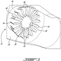
Fig. 2 is a rear isometric view of a forced exhaust mixer; -
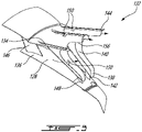
Fig. 3 is an oblique view of a forced exhaust mixer, in accordance with an embodiment; -
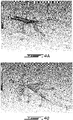
Fig. 4A and Fig. 4B present flow simulation results using the mixer ofFig. 3 ; -
Fig. 5 is an oblique view of a forced exhaust mixer, in accordance with another embodiment; -
Fig. 6 presents flow simulation results using the mixer ofFig. 5 ; -
Fig. 7 is an oblique view of a forced exhaust mixer, in accordance with another embodiment; -
Fig. 8 presents flow simulation results using the mixer ofFig. 7 ; -
Fig. 9A and 9B are heat maps showing flow temperature at a first axial position, with and without an aperture, respectively; -
Fig. 10A and 10B are heat maps showing flow temperature at a second axial position, with and without an aperture, respectively; and -
Fig. 11 presents a graph showing maximum turbulent kinetic energy at different axial sections for different mixer configurations. -
Fig. 1 illustrates a turbofangas turbine engine 10 of a type preferably provided for use in subsonic flight, generally comprising in serial flow communication afan 12 through which ambient air is propelled, amultistage compressor 14 for pressurizing the air, acombustor 16 in which the compressed air is mixed with fuel and ignited for generating an annular stream of hot combustion gases, and aturbine section 18 for extracting energy from the combustion gases. - The
gas turbine engine 10 includes afirst casing 20 which encloses the turbo machinery of the engine, and a second,outer casing 22, sometimes referred to as a bypass duct, extending outwardly of thefirst casing 20 such as to define anannular bypass passage 24 therebetween. The air propelled by thefan 12 is split into a first portion which flows around thefirst casing 20 within thebypass passage 24, and a second portion which flows through acore gas path 26 which is defined within thefirst casing 20 and allows the flow to circulate through themultistage compressor 14,combustor 16 andturbine section 18 as described above. - At the aft end of the
engine 10, a component commonly referred to as acenterbody 28, shaped somewhat as an axisymmetrical bullet, is centered on alongitudinal axis 30 of theengine 10 and defines a downstream portion of an inner wall of thecore flow path 26 so that the combustion gases flow therearound as they exit to the atmosphere. Anexhaust mixer 32 has a conduit extending radially between the bypass duct and the centerbody, forming a radially outer limitation to the core gas path and a radially inner limitation to the bypass flow path. Themixer 32 conduit acting as a rearmost portion of the outer wall defining thecore flow path 26 and a rearmost portion of the inner wall defining thebypass passage 24. The hot combustion gases from thecore flow path 26 and the cooler air from thebypass passage 24 are, thus, mixed together by themixer 32 at the exit thereof such as to produce a combined exhaust stream having a somewhat averaged temperature. - As shown in
Fig. 2 , themixer 32 may include an annularsheet metal wall 34 defining anupstream end 36 along which the flows from thecore flow path 26 and from thebypass passage 24 are received, and adownstream end 38 where the two flows meet and are mixed together. Theannular wall 34 defines a plurality of circumferentially distributed lobes. The lobes include alternating inner andouter lobes 40 orvalleys 42 andcrests 44, with thecrests 44 extending radially outwardly into thebypass passage 24 and thevalleys 42 extending radially inwardly into thecore flow path 26. As such, thevalleys 42 define troughs in thebypass passage 24 in between adjacent ones of thecrests 44, while thecrests 44 define troughs in thecore flow path 26 in between adjacent ones of thevalleys 42. It will be noted that the schematic image presented inFig. 1 can be associated to a short cowl engine example, and that in many alternate embodiments, the engine can be a long cowl engine instead. Moreover, it will be noted that while the lobes are regularly shaped around the circumference, alternate embodiments may have some form of irregularity to the lobe shape, such as to accommodate the flow geometry disruptions caused by upstream features for instance. - In alternate embodiments, such as ones commonly referred to as confluent mixer design, the
mixer 32 can have a simple annular conduit leading to thedownstream end 38 rather than thelobes 40. - In an embodiment such as the one shown in
Fig. 2 , thelobes 40 can be used to produce greater thrust with a given fluid energy and therefore reduce fuel consumption, for instance. The design space of thelobes 40 can include lobe-counts, lobe-penetration, area ratio, scallop-shapes etc. These geometries can induce very efficient mixing of thecore 26 andbypass 24 streams by the creation of strong vortical flow structures in streamwise and radial directions, with the typically undesired side-effect of noise generation. - The
exhaust mixer 32 can induce strong vortical flow structures comprising of both small-scale turbulence and/or large scale eddies within the flow. The creation of fine-scale turbulence can be driven by geometric details of themixer 32 and can have a strong influence on the generation of medium to high frequency noise, which can be the dominant source of noise from approximately 70 to 110 degrees from thelongitudinal axis 30 of the engine 10 (inlet considered 0 degrees). On the other hand, large scale eddies can be created by the coalescence of fine/small scale turbulent eddies that interact and propagate downstream thereby creating low frequency noise, which can be the dominant source of noise beyond 130 degrees from thelongitudinal axis 30 for instance. - A design which increases the mixing efficiency, and thus the thrust, at a relativelyhigh cost in terms of noise generation can be qualified as "aggressive", for instance. In some cases, less aggressive designs will be favored, at the cost of the additional thrust,simply because a hard limit is imposed in terms of noise generation. Different limits in terms of noise generation can be imposed on different frequencies of noise. The
mixer 32 can contribute to increasing the perceived noise level in the mid-frequency content, for instance, and may penalize the aircraft during certification flight tests. - Selecting a less
aggressive mixer 32 design may imply, depending on the specific application, reducing the axial and/or radial span of thelobes 40, the number oflobes 40, or even omitting thelobes 40 entirely, for instance, and may help satisfy noise level requirements at the cost of thrust and fuel economy. - It was found that at least in some embodiments, mixing efficiency could be improved by giving the
bypass 24 andcore 26 flows the opportunity of an early start at mixing. Moreover, it was found that in such embodiments, the increased mixing efficiency could be achieved without the inconveniences associated to higher noise generation. This early start at mixing can be provided by providing apertures in the mixer's 32 conduit, upstream of the downstream end/trailingedge 38 of the conduit. The apertures can be circumferentially distributed around the circumference of the conduit and create fluid connections between thebypass flow path 24 and thecore flow path 26. The fine scale turbulence created due to these holes can contribute to the mixing efficiency while the noise generated in the process can be shielded by the dominant mixing created by the trailingedge 38 of themixer 32. -
Fig. 3 presents an example of anexhaust mixer 132 being designed in a mannerto provide such an opportunity of an early start at mixing. In the embodiment presented inFig. 3 , the mixer'sconduit 134 is of the forced mixing type, and thus includes apluralityof lobes 140, similar to the embodiment shown inFig. 2 . The mixer'sconduit 134 spans a portion of thecenterbody 128, extending axially from an annularupstream end 136, or segment, to the alternatingly radially fanningcrests 144 andvalleys 142 towards thedownstream edge 138. In this embodiment, an annular segment of theconduit 134 extends downstream of the rearmostturbine exhaust strut 146 to the point or points where thecrests 144 andvalleys 142 start forming. Adownstream end 138 portion of thevalleys 142 can be structurally connected to thecenterbody 128 via support struts 148, for instance. It will be noted that the support struts are specific to the illustrated embodiment and may be absent in alternate embodiments. Depending on the embodiment, theapertures 150 can be formed through one, or both, of thecrests 144 andvalleys 142, and/or be defined across the annular segment, for instance. In the embodiment presented inFig. 3 ,rectangular apertures 150 are formed roughly midway along both thecrests 144 and thevalleys 142. Thecrests 144 andvalleys 142 being regularly configured, theapertures 150 are regularly spaced apart from one another around the periphery. The effect on the flow is presented in the simulation results presented inFig. 4A and 4B . As shown inFig. 4A ,colder flow 152 from thebypass flow path 124 can penetrate theapertures 150 formed through thecrests 144 and give an early start to mixing with thehotter flow 154, while also potentially causing some fine turbulence which can be beneficial to mixing downstream. As shown inFig. 4A , the portion of thecolder flow 152 which penetrates into the hotter exhaust flow tends to remain close to thecrest 144 as it travels towards the trailingedge 138 of theconduit 134. As shown inFig. 4B ,hotter flow 154 from thecore flow path 126 penetrates theapertures 150 formed through thevalleys 142 and gives an early start to mixing with thecolder flow 152, while also potentially causing some fine turbulence which can be beneficial to mixing downstream. Any noise generated by the early penetration of each flow into the other can remain significantly shielded from the atmosphere, especially when the length of the exhaust nozzle is significant, and thereby have a limited effect, if any, on the overall perceived noise levels. It will be noted that the particular embodiment presented inFig. 3 hasscallops 156 formed in the radially extending portions of the trailingedge 138, which is one of several possible design choices. Chevrons can be preferred in other embodiments, or straight edges. In the specific embodiment presented inFig. 3 , theapertures 150 are short rectangular, almost square. -
Fig. 5 presents yet another embodiment of anexhaust mixer 232. In the embodiment presented inFig. 5 , theapertures 250 are circular, without scoops.Fig. 6 presents the simulation results using thecircular apertures 250 shown inFig. 5 , and it can be seen that suitable results can also be achieved with circular apertures, comparable to the square-shapedapertures 150 presented above in relation withFig. 3 .Accordingly, since both rectangular 150 andcircular apertures 250 can provide good results, it is considered that elliptical apertures, and other aperture shapes could also likely work. -
Fig. 7 presents yet another embodiment of anexhaust mixer 332 in which theapertures 350 are elongated rectangular, with a length oriented stream-wise as shown. Flow simulation results are presented inFig. 8 . -
Figs 9A and 9B, and Figs. 10A and 10B , both provide additional flow simulation results comparing an embodiment with the rectangular apertures such as presented inFig. 7 (Fig. 9B and 10B ), with an identical embodiment except without the rectangular apertures (Fig. 9A and 10A ). The simulation results of these figures are transversal cross section heat maps showing a representative portion of around the circumference, withFigs 9A and 9B being taken immediately downstream of the axial location of the apertures, andFigs. 10A and 10B being taken downstream of the trailing edge of the conduit.Fig. 9B shows the occurrence of pre-mixing 400 ofcore 426 and bypass flows 424 in the mixing plane using the apertures.Fig. 10B shows the deeper penetration of thecold flow 452 achieved using the apertures. Thus demonstrating the ability to customize and optimize the flow-field downstream of the mixer. -
Fig. 11 is agraph 500 showing the variations in max turbulent kinetic energy vs. axial planes for the mixer withrectangular apertures 502 and withoutapertures 504, of the same configurations used to produceFigs. 9A, 9B, 10A and 10B . Different aperture geometries can exhibits different flow topologies downstream of the mixer. - The embodiments described in this document provide non-limiting examples of possible implementations of the present technology. Upon review of the present disclosure, a person of ordinary skill in the art will recognize that changes may be made to the embodiments described herein without departing from the scope of the present technology. For example, in some embodiments, it can be preferred to introduce apertures in an annular portion of the conduit. This can be useful in an annular portion of the conduit, upstream of the crests and valleys, in a forced mixer-type conduit, or in an annular conduit (non-forced mixing). In practice, there can be more benefit, to a certain extent, to introducing the apertures as upstream as possible, but without otherwise interfering with the operation of the turbofan. The apertures can be located at any suitable position between the turbine section and the trailing edge of the conduit, for instance. Depending on the embodiment, the pre-mixing apertures can be integrated with the hardware forming the wall between the core engine and the bypass path. The apertures can be permanent, or be made to be commanded to open and close by mechanical, electrical, magnetic, hydraulic or other suitable means. The command to open or close can be initiated manually by the pilot, or be automated by integrating it into the control system. The pre-mixing slots can also be actuated to open or close using thermally responsive components, such as bi-metallic strips. Similarly, pre-mixing slots can be actuated to open or close using thermally-responsive smart materials like Ti-Ni alloys or the like. The apertures can be introduced for any suitable goal, such as thrust increase, noise reduction, etc. Yet further modifications could be implemented by a person of ordinary skill in the art in view of the present disclosure, which modifications would be within the scope of the present technology.
Claims (15)
- An exhaust mixer (32; 132; 232; 332) comprising a conduit (134) extending around a central axis and along the axis to a downstream end (38; 138), the conduit (134) extending between a radially-outer bypass path (24; 124) and a radially-inner core gas path (26; 126), the conduit (134) having a plurality of apertures (150; 250; 350) spaced-apart from one another around a circumference of the conduit (134) and fluidly connecting the bypass path (24; 124) to the core gas path (26; 126) upstream of the downstream end (38; 138).
- The exhaust mixer of claim 1, wherein the apertures (250) are circular apertures (250) equally interspaced from one another around the circumference of the conduit (134).
- The exhaust mixer of claim 1, wherein the apertures (150; 350) are rectangular apertures (350) equally interspaced from one another around the circumference of the conduit (134).
- The exhaust mixer of claim 1, 2 or 3, being of a forced mixer type, wherein the conduit (134) has a plurality of circumferentially distributed lobes (140) at the downstream end (138), the lobes (140) including alternating valleys (142) and crests (144), the valleys (142) and crests (144) having respective upstream ends merging with an annular segment of the conduit (134) and fanning out in opposite radial orientations from the upstream ends to the downstream end (138).
- The exhaust mixer of claim 4, wherein the apertures (150; 250; 350) are disposed in the valleys (142).
- The exhaust mixer of claim 4, wherein the apertures (150; 250; 350) are disposed in the crests (144).
- The exhaust mixer of claim 4, wherein the apertures (150; 250; 350) are disposed both in the crests (144) and in the valleys (142).
- The exhaust mixer of any of claims 4 to 7, wherein the downstream end (138) has radially oriented portions (156) between the valleys (142) and crests (144), the radially oriented portions (156) being scalloped axially inwardly.
- A turbofan engine (10) comprising the exhaust mixer (32...332) of any preceding claim.
- A method of operating a turbofan engine (12) including separating an intake flow into a coregas flow (26; 126) and a bypass flow (24; 124), generating a hot annular stream (154) of combustion gasses exiting a combustion chamber (16) in the core gas flow (26; 126), and recombining the core gas flow (26; 126) and the bypass flow (24; 124) downstream of the combustion chamber (16), the method comprising pre-mixinga portion of at least one of the core gas flow (26; 126) and the bypass flow (24; 124) with the other downstream of the combustion chamber (16) and upstream of recombining the core gas flow (26; 126) and the bypass flow (24; 124).
- The method of claim 10, further comprising forcing the mixing of the core gas flow (26; 126) and the bypass flow (24; 124) including creating radially extending and circumferentially alternating plumes of core gas flow (26; 126) and bypass flow (24; 124) immediately upstream of said recombining.
- The method of claim 11, wherein the pre-mixing is performed during the formation of the plumes.
- The method of claim 11 or 12, wherein the pre-mixing includes pre-mixing a portion of both the core gas flow (26; 126) and the bypass flow (24; 124) with the other within the plumes.
- The method of any of claims 10 to 13, further comprising compressing the core gas flow (26; 126) upstream of the combustion chamber (16) with a compressor (14), and extracting energy from the combustion gasses downstream of the combustion chamber (16) with a turbine (18), and driving the compressor (14) with the turbine (18).
- The method of claim 14 further comprising compressing the bypass flow (24; 124) using a fan (12), and driving the fan (12) with the turbine (18).
Applications Claiming Priority (1)
| Application Number | Priority Date | Filing Date | Title |
|---|---|---|---|
| US16/953,935 US20220161205A1 (en) | 2020-11-20 | 2020-11-20 | Exhaust mixer |
Publications (1)
| Publication Number | Publication Date |
|---|---|
| EP4001627A1 true EP4001627A1 (en) | 2022-05-25 |
Family
ID=78709356
Family Applications (1)
| Application Number | Title | Priority Date | Filing Date |
|---|---|---|---|
| EP21209386.8A Withdrawn EP4001627A1 (en) | 2020-11-20 | 2021-11-19 | Exhaust mixer |
Country Status (3)
| Country | Link |
|---|---|
| US (1) | US20220161205A1 (en) |
| EP (1) | EP4001627A1 (en) |
| CA (1) | CA3139351A1 (en) |
Citations (4)
| Publication number | Priority date | Publication date | Assignee | Title |
|---|---|---|---|---|
| US4819425A (en) * | 1982-03-18 | 1989-04-11 | The Boeing Company | Primary-secondary ventilated flow mixer nozzle for high bypass turbo fan jet propulsion system |
| US20030182925A1 (en) * | 2002-02-22 | 2003-10-02 | Jean-Pierre Lair | Duplex mixer exhaust nozzle |
| EP3150836A1 (en) * | 2015-10-02 | 2017-04-05 | Pratt & Whitney Canada Corp. | Integrated tec/mixer strut axial position |
| US20180142562A1 (en) * | 2015-05-12 | 2018-05-24 | Safran Aircraft Engines | Turbine Engine Comprising a Lobed Mixer Having Scoops |
Family Cites Families (18)
| Publication number | Priority date | Publication date | Assignee | Title |
|---|---|---|---|---|
| US3587777A (en) * | 1969-10-23 | 1971-06-28 | Rohr Corp | Turbofan propulsion apparatus with silencer and operating method |
| US3592291A (en) * | 1969-11-17 | 1971-07-13 | Rohr Corp | Method and apparatus for suppressing the noise and augmenting the thrust of a jet engine |
| US4077206A (en) * | 1976-04-16 | 1978-03-07 | The Boeing Company | Gas turbine mixer apparatus for suppressing engine core noise and engine fan noise |
| US4335801A (en) * | 1980-12-15 | 1982-06-22 | The Boeing Company | Noise suppressing nozzle |
| US6276127B1 (en) * | 1999-06-22 | 2001-08-21 | John R. Alberti | Noise suppressing mixer for jet engines |
| US7017331B2 (en) * | 2002-12-07 | 2006-03-28 | Anderson Jack H | Jet nozzle mixer |
| US20070000234A1 (en) * | 2005-06-30 | 2007-01-04 | Anderson Jack H | Jet nozzle mixer |
| US8734085B2 (en) * | 2009-08-17 | 2014-05-27 | Pratt & Whitney Canada Corp. | Turbine section architecture for gas turbine engine |
| DE102012220358A1 (en) * | 2012-11-08 | 2014-06-12 | Rolls-Royce Deutschland Ltd & Co Kg | Nozzle with guide devices |
| US20150075169A1 (en) * | 2013-09-19 | 2015-03-19 | Pratt & Whitney Canada Corp. | Integrated turbine exhaust struts and mixer of turbofan engine |
| US9759159B2 (en) * | 2014-05-26 | 2017-09-12 | Pratt & Whitney Canada Corp. | Integrated turbine exhaust struts and mixer of turbofan engine |
| US10018150B2 (en) * | 2014-05-26 | 2018-07-10 | Pratt & Whitney Canada Inc. | Integrated TEC/mixer strut axial position |
| US10451001B2 (en) * | 2014-12-09 | 2019-10-22 | Rolls-Royce Corporation | CMC oxide-oxide mixer design |
| US10544755B2 (en) * | 2016-09-20 | 2020-01-28 | Rolls-Royce North American Technologies, Inc. | Variable infrared suppression system in a gas turbine engine |
| DE102016222583A1 (en) * | 2016-11-16 | 2018-05-17 | Rolls-Royce Deutschland Ltd & Co Kg | Mixer for an engine made of at least one composite material, manufacturing method and manufacturing device |
| US11118481B2 (en) * | 2017-02-06 | 2021-09-14 | Raytheon Technologies Corporation | Ceramic matrix composite turbine exhaust assembly for a gas turbine engine |
| US10801441B2 (en) * | 2018-02-20 | 2020-10-13 | Pratt & Whitney Canada Corp. | Flow mixer stiffener ring segmented springs |
| FR3087847B1 (en) * | 2018-10-25 | 2020-12-25 | Safran Aircraft Engines | LOBE MIXER PROMOTING THE MIXING OF CONFLUENT FLOWS |
-
2020
- 2020-11-20 US US16/953,935 patent/US20220161205A1/en active Pending
-
2021
- 2021-11-17 CA CA3139351A patent/CA3139351A1/en active Pending
- 2021-11-19 EP EP21209386.8A patent/EP4001627A1/en not_active Withdrawn
Patent Citations (4)
| Publication number | Priority date | Publication date | Assignee | Title |
|---|---|---|---|---|
| US4819425A (en) * | 1982-03-18 | 1989-04-11 | The Boeing Company | Primary-secondary ventilated flow mixer nozzle for high bypass turbo fan jet propulsion system |
| US20030182925A1 (en) * | 2002-02-22 | 2003-10-02 | Jean-Pierre Lair | Duplex mixer exhaust nozzle |
| US20180142562A1 (en) * | 2015-05-12 | 2018-05-24 | Safran Aircraft Engines | Turbine Engine Comprising a Lobed Mixer Having Scoops |
| EP3150836A1 (en) * | 2015-10-02 | 2017-04-05 | Pratt & Whitney Canada Corp. | Integrated tec/mixer strut axial position |
Also Published As
| Publication number | Publication date |
|---|---|
| US20220161205A1 (en) | 2022-05-26 |
| CA3139351A1 (en) | 2022-05-20 |
Similar Documents
| Publication | Publication Date | Title |
|---|---|---|
| EP1561939B1 (en) | Sinuous chevron exhaust nozzle | |
| JP6063246B2 (en) | Compact high pressure exhaust silencer | |
| US7921652B2 (en) | Aeroengine bleed valve | |
| AU2019264621B2 (en) | Involute trapped vortex combustor assembly | |
| JP5264184B2 (en) | Bleed structure for a bleed passage in a gas turbine engine | |
| CN102434232B (en) | Turbine exhaust plenum | |
| EP2383455A2 (en) | Gas turbine engine exhaust mixer | |
| EP2083164A2 (en) | Aeroengine bleed valve | |
| EP2196626A2 (en) | A gas turbine engine | |
| EP2778380A2 (en) | Gas turbine engine exhaust mixer with aerodynamic struts | |
| US9644496B2 (en) | Radial diffuser exhaust system | |
| US20070012046A1 (en) | Gas turbine intermediate structure and a gas turbine engine comprising the intermediate structure | |
| EP2851516A1 (en) | Integrated turbine engine exhaust struts and mixer of turbofan engine | |
| CN110494693B (en) | Single-cavity trapped vortex burner | |
| EP3181880B1 (en) | Gas turbine engine exhaust mixer with lobes cross-over offset | |
| EP3048282A1 (en) | A gas turbine engine and blocker door assembly | |
| US20220161205A1 (en) | Exhaust mixer | |
| EP1856398B1 (en) | A bleed structure for a bleed passage in a gas turbine engine | |
| JP2019007483A (en) | Protective baffles for gas turbine noise attenuation system | |
| EP3260694A1 (en) | Gas turbine exhaust cooling system | |
| EP2527618A2 (en) | A bleed flow discharge device of a gas turbine engine | |
| US11965653B2 (en) | Dilution air inlets with notched tip and slotted tail for combustor | |
| US20190353054A1 (en) | Exhaust system for a gas turbine engine | |
| EP4400707A1 (en) | Exhaust mixer with protrusions | |
| EP4400709A1 (en) | Exhaust mixer with protrusions |
Legal Events
| Date | Code | Title | Description |
|---|---|---|---|
| PUAI | Public reference made under article 153(3) epc to a published international application that has entered the european phase |
Free format text: ORIGINAL CODE: 0009012 |
|
| STAA | Information on the status of an ep patent application or granted ep patent |
Free format text: STATUS: THE APPLICATION HAS BEEN PUBLISHED |
|
| AK | Designated contracting states |
Kind code of ref document: A1 Designated state(s): AL AT BE BG CH CY CZ DE DK EE ES FI FR GB GR HR HU IE IS IT LI LT LU LV MC MK MT NL NO PL PT RO RS SE SI SK SM TR |
|
| STAA | Information on the status of an ep patent application or granted ep patent |
Free format text: STATUS: THE APPLICATION IS DEEMED TO BE WITHDRAWN |
|
| 18D | Application deemed to be withdrawn |
Effective date: 20221126 |