EP4001617B1 - Engine using cracked ammonia fuel - Google Patents
Engine using cracked ammonia fuel Download PDFInfo
- Publication number
- EP4001617B1 EP4001617B1 EP21209410.6A EP21209410A EP4001617B1 EP 4001617 B1 EP4001617 B1 EP 4001617B1 EP 21209410 A EP21209410 A EP 21209410A EP 4001617 B1 EP4001617 B1 EP 4001617B1
- Authority
- EP
- European Patent Office
- Prior art keywords
- flow
- ammonia
- heat exchanger
- compressor
- recited
- Prior art date
- Legal status (The legal status is an assumption and is not a legal conclusion. Google has not performed a legal analysis and makes no representation as to the accuracy of the status listed.)
- Active
Links
Images


Classifications
-
- F—MECHANICAL ENGINEERING; LIGHTING; HEATING; WEAPONS; BLASTING
- F02—COMBUSTION ENGINES; HOT-GAS OR COMBUSTION-PRODUCT ENGINE PLANTS
- F02C—GAS-TURBINE PLANTS; AIR INTAKES FOR JET-PROPULSION PLANTS; CONTROLLING FUEL SUPPLY IN AIR-BREATHING JET-PROPULSION PLANTS
- F02C7/00—Features, components parts, details or accessories, not provided for in, or of interest apart form groups F02C1/00 - F02C6/00; Air intakes for jet-propulsion plants
- F02C7/22—Fuel supply systems
- F02C7/224—Heating fuel before feeding to the burner
-
- C—CHEMISTRY; METALLURGY
- C01—INORGANIC CHEMISTRY
- C01B—NON-METALLIC ELEMENTS; COMPOUNDS THEREOF; METALLOIDS OR COMPOUNDS THEREOF NOT COVERED BY SUBCLASS C01C
- C01B3/00—Hydrogen; Gaseous mixtures containing hydrogen; Separation of hydrogen from mixtures containing it; Purification of hydrogen; Reversible storage of hydrogen
- C01B3/02—Production of hydrogen; Production of gaseous mixtures containing hydrogen
- C01B3/04—Production of hydrogen; Production of gaseous mixtures containing hydrogen by decomposition of inorganic compounds
- C01B3/047—Decomposition of ammonia
-
- F—MECHANICAL ENGINEERING; LIGHTING; HEATING; WEAPONS; BLASTING
- F02—COMBUSTION ENGINES; HOT-GAS OR COMBUSTION-PRODUCT ENGINE PLANTS
- F02C—GAS-TURBINE PLANTS; AIR INTAKES FOR JET-PROPULSION PLANTS; CONTROLLING FUEL SUPPLY IN AIR-BREATHING JET-PROPULSION PLANTS
- F02C3/00—Gas-turbine plants characterised by the use of combustion products as the working fluid
- F02C3/04—Gas-turbine plants characterised by the use of combustion products as the working fluid having a turbine driving a compressor
-
- F—MECHANICAL ENGINEERING; LIGHTING; HEATING; WEAPONS; BLASTING
- F02—COMBUSTION ENGINES; HOT-GAS OR COMBUSTION-PRODUCT ENGINE PLANTS
- F02C—GAS-TURBINE PLANTS; AIR INTAKES FOR JET-PROPULSION PLANTS; CONTROLLING FUEL SUPPLY IN AIR-BREATHING JET-PROPULSION PLANTS
- F02C3/00—Gas-turbine plants characterised by the use of combustion products as the working fluid
- F02C3/20—Gas-turbine plants characterised by the use of combustion products as the working fluid using a special fuel, oxidant, or dilution fluid to generate the combustion products
- F02C3/22—Gas-turbine plants characterised by the use of combustion products as the working fluid using a special fuel, oxidant, or dilution fluid to generate the combustion products the fuel or oxidant being gaseous at standard temperature and pressure
-
- F—MECHANICAL ENGINEERING; LIGHTING; HEATING; WEAPONS; BLASTING
- F23—COMBUSTION APPARATUS; COMBUSTION PROCESSES
- F23R—GENERATING COMBUSTION PRODUCTS OF HIGH PRESSURE OR HIGH VELOCITY, e.g. GAS-TURBINE COMBUSTION CHAMBERS
- F23R3/00—Continuous combustion chambers using liquid or gaseous fuel
- F23R3/28—Continuous combustion chambers using liquid or gaseous fuel characterised by the fuel supply
- F23R3/36—Supply of different fuels
-
- F—MECHANICAL ENGINEERING; LIGHTING; HEATING; WEAPONS; BLASTING
- F02—COMBUSTION ENGINES; HOT-GAS OR COMBUSTION-PRODUCT ENGINE PLANTS
- F02C—GAS-TURBINE PLANTS; AIR INTAKES FOR JET-PROPULSION PLANTS; CONTROLLING FUEL SUPPLY IN AIR-BREATHING JET-PROPULSION PLANTS
- F02C6/00—Plural gas-turbine plants; Combinations of gas-turbine plants with other apparatus; Adaptations of gas-turbine plants for special use
- F02C6/18—Plural gas-turbine plants; Combinations of gas-turbine plants with other apparatus; Adaptations of gas-turbine plants for special use using the waste heat of gas-turbine plants outside the plants themselves, e.g. gas-turbine power heat plants
-
- F—MECHANICAL ENGINEERING; LIGHTING; HEATING; WEAPONS; BLASTING
- F05—INDEXING SCHEMES RELATING TO ENGINES OR PUMPS IN VARIOUS SUBCLASSES OF CLASSES F01-F04
- F05D—INDEXING SCHEME FOR ASPECTS RELATING TO NON-POSITIVE-DISPLACEMENT MACHINES OR ENGINES, GAS-TURBINES OR JET-PROPULSION PLANTS
- F05D2220/00—Application
- F05D2220/30—Application in turbines
- F05D2220/32—Application in turbines in gas turbines
-
- F—MECHANICAL ENGINEERING; LIGHTING; HEATING; WEAPONS; BLASTING
- F23—COMBUSTION APPARATUS; COMBUSTION PROCESSES
- F23R—GENERATING COMBUSTION PRODUCTS OF HIGH PRESSURE OR HIGH VELOCITY, e.g. GAS-TURBINE COMBUSTION CHAMBERS
- F23R2900/00—Special features of, or arrangements for continuous combustion chambers; Combustion processes therefor
- F23R2900/00002—Gas turbine combustors adapted for fuels having low heating value [LHV]
-
- Y—GENERAL TAGGING OF NEW TECHNOLOGICAL DEVELOPMENTS; GENERAL TAGGING OF CROSS-SECTIONAL TECHNOLOGIES SPANNING OVER SEVERAL SECTIONS OF THE IPC; TECHNICAL SUBJECTS COVERED BY FORMER USPC CROSS-REFERENCE ART COLLECTIONS [XRACs] AND DIGESTS
- Y02—TECHNOLOGIES OR APPLICATIONS FOR MITIGATION OR ADAPTATION AGAINST CLIMATE CHANGE
- Y02E—REDUCTION OF GREENHOUSE GAS [GHG] EMISSIONS, RELATED TO ENERGY GENERATION, TRANSMISSION OR DISTRIBUTION
- Y02E60/00—Enabling technologies; Technologies with a potential or indirect contribution to GHG emissions mitigation
- Y02E60/30—Hydrogen technology
- Y02E60/36—Hydrogen production from non-carbon containing sources, e.g. by water electrolysis
-
- Y—GENERAL TAGGING OF NEW TECHNOLOGICAL DEVELOPMENTS; GENERAL TAGGING OF CROSS-SECTIONAL TECHNOLOGIES SPANNING OVER SEVERAL SECTIONS OF THE IPC; TECHNICAL SUBJECTS COVERED BY FORMER USPC CROSS-REFERENCE ART COLLECTIONS [XRACs] AND DIGESTS
- Y02—TECHNOLOGIES OR APPLICATIONS FOR MITIGATION OR ADAPTATION AGAINST CLIMATE CHANGE
- Y02T—CLIMATE CHANGE MITIGATION TECHNOLOGIES RELATED TO TRANSPORTATION
- Y02T50/00—Aeronautics or air transport
- Y02T50/60—Efficient propulsion technologies, e.g. for aircraft
- Y02T50/678—Aviation using fuels of non-fossil origin
Definitions
- a gas turbine engine typically mixes a carbon-based fuel with air within a combustor where it is ignited to generate a high-energy exhaust gas flow.
- the high-energy exhaust gas flow includes carbon that is eventually exhausted into the environment.
- Alternative engine structures and fuels may aid in the reduction and/or elimination of carbon emissions.
- One such alternative fuel is ammonia.
- Turbine engine manufacturers continue to seek further improvements to engine performance including improvements to reduce environmental impact while improving propulsive efficiencies.
- WO 2020189566 A1 describes an ammonia decomposition facility is equipped with: a heating medium line through which a heating medium that is heated with heat generated in a gas turbine flows; an ammonia feeding line through which ammonia flows; an ammonia decomposition device; and an ammonia removal device.
- a gas turbine plant is provided with a gas turbine, a heating device, a decomposition gas line, and a decomposition gas compressor.
- the heating device heats ammonia and thermally decomposes the ammonia to convert the ammonia into decomposition gas (PG) including hydrogen gas and nitrogen gas.
- PG decomposition gas
- EP 3517757 A1 describes a method for operating a power device, the power device comprises a gas turbine and an exhaust gas system for treatment of exhaust gas, wherein the gas turbine comprises a combustion chamber and a turbine.
- DE 102015213930 A1 describes a gas turbine power plant for generating useful energy, preferably electrical energy, with a gas turbine which has a compressor, a combustion chamber and a turbine on a shaft and which can be charged with a process gas , which is capable of reacting with air to release energy.
- the gas turbine engine further includes a pump that is configured to increase a pressure of the ammonia flow to a pressure above 5 atm (74 psi) at the cracking device.
- the ammonia flow is communicated to the cracking device at a pressure between 5 atm (74 psi) and 300 atm (4410 psi).
- the ammonia flow is heated to a temperature at a temperature between 500 °C (935 °F) and 700 °C (1292 °F).
- the ammonia flow is heated to a temperature at a temperature above 700 °C (1292 °F).
- the flow of component parts includes Hydrogen (H 2 ) and Nitrogen (N 2 ).
- the compressor heat exchanger includes an exhaust heat exchanger that provides thermal communication between the ammonia flow and exhaust heat from the turbine section.
- the compressor heat exchanger that provides thermal communication between the ammonia flow and compressed air from a last stage of the compressor section.
- the compressed air from a last stage of the compressor section that is in thermal communication with the ammonia is subsequently in thermal communication with the combustor to provide combustor cooling.
- the compressed air from a last stage of the compressor section that is in thermal communication with the ammonia is subsequently in thermal communication with the turbine to provide combustor cooling.
- the compressor heat exchanger that provides thermal communication between the ammonia flow and compressor air from an intermediate stage of the compressor section.
- a combustor heat exchanger that provides thermal communication from cooling air after it has cooled the combustor.
- a combustor heat exchanger that provides thermal communication from cooling air after it has cooled the turbine.
- the ammonia flow is heated prior to entering the cracking device.
- the ammonia flow is heated in the cracking device.
- the gas turbine engine further includes a turboexpander that receives the ammonia flow and the flow of component parts from the cracker.
- the ammonia flow and the flow of component parts are expanded through the turboexpander to drive a mechanical output.
- the pressure is raised to between 5 atm (74 psi) and 300 atm (4410 psi).
- the heat exchanger heats the ammonia to a temperature between 500 °C (935 °F) and 700 °C (1292 °F).
- the heat exchanger heats the ammonia flow to a temperature above 700 °C (1292 °F).
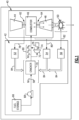
- FIG. 1 schematically illustrates an example alternate fueled turbine engine assembly 40.
- the engine assembly 40 uses an ammonia-based fuel flow 60 mixed with a core gas flow 62 in a combustor 46 to generate a high energy gas flow 64 that expands through a turbine section 48 to drive a compressor section 44.
- the engine 40 is shown schematically and that other structures and engine configurations such as 2-spool, 3-spool and geared turbofan engines would benefit from this disclosure and are within the contemplation and scope of this disclosure.
- a land-based turbine engine would also benefit from application of the features of this disclosure.
- the disclosed ammonia-based fuel comprises decomposition products of ammonia (NH 3 ) and/or a mixture of ammonia (NH 3 ) and the decomposition products provided by a fuel system 42.
- Ammonia does not contain carbon, but does have a fuel energy similar to alcohols such as methanol. Ammonia can also be transported and stored in liquid form at moderate pressure and temperature. For example, ammonia is a liquid at a pressure of about 8.5 atm (125 psi) and a temperature of 20 °C (68 °F). Alternatively, ammonia is a liquid at a pressure of 1 atm and a temperature of -33 °C (-27 °F). Moreover, because ammonia does not contain carbon it may be heated to temperatures above that of a hydrocarbon fuel without forming carbon deposits on portions of a fuel system. The increased temperature capabilities of ammonia provide an increased heat sink capacity that can improve engine efficiency. Ammonia can be decomposed into hydrogen and nitrogen component parts. Hydrogen provides improved combustion properties and a desirable clean burning fuel that does not generate undesirable exhaust products. Additionally, removal of nitrogen from the ammonia can reduce nitrous oxide emissions.
- the disclosed fuel system 42 uses heat to decompose a flow of ammonia fuel 58 into mostly component parts of hydrogen and nitrogen.
- the component parts of hydrogen and nitrogen along with residual ammonia are communicated to the combustor 46 to produce the high energy gas flow 64.
- the ammonia fuel 58 is stored in a fuel storage tank 66 and pressurized by a fuel pump 68 to a higher level for communication into the combustor 46.
- the pressurized ammonia fuel flow 58 is communicated to a cracker assembly 70 for decomposition into the component parts of hydrogen and nitrogen.
- the decomposition process utilizes thermal energy that is drawn from locations on the engine 40.
- the decomposition or conversion process of ammonia into component parts of hydrogen and nitrogen can reach an equilibrium point shown at 22 based on a temperature indicated at 24 and pressure indicated by lines 26, 28, 30 and 32. Decomposition or conversion progresses toward the equilibrium value in the presence of a catalyst that sufficiently promotes the reaction with enough heat supplied for the reaction to proceed. At very low pressures, a very high percentage of ammonia can be converted into hydrogen and nitrogen in the cracker assembly 70 as indicated at 32. The percentage of ammonia converted into component parts at pressures around 1 atm (14 psi) can approach 100% at temperatures above around 300 °C (572 °F). However, higher pressures are needed to communicate the components of the fuel into the combustor 46.
- the degree of conversion decreases as the pressure of the ammonia fuel increases, as is shown by graph 20. At pressures of around 68 atm (1000 psi), the degree of conversion is reduced to below 70% at 400 °C as is indicated at 30. The degree of conversion at the same pressure increases with an increase in temperature. In this example, the conversion increases to over 80% at temperatures above around 500 °C. Higher pressures require higher temperatures to achieve conversions above 80%. At a pressure of 136 atm (2000 psi), the temperature needed to achieve 80% conversion exceeds 500 °C (932 °F) as indicated by line 28. At a pressure of 272 atm (4000 psi), indicated by line 26, the temperature needed to achieve 80% conversion exceeds 600 °C (1112 °F).
- the example fuel system 42 uses thermal energy from the engine 40 to elevate the temperature of the ammonia fuel flow in view of the pressure required to generate the desired degree of decomposition.
- Thermal energy is drawn from various heat sources including heat producing engine systems as is schematically shown at 78, 80 and 82 in Figure 1 .
- the heat drawn from the various heat sources is communicated to the cracker assembly 70 as is indicated by arrows 84 to aid and encourage the cracking and decomposition process.
- heat is drawn from at least one of several locations within the engine assembly 40. Heat from each location is communicated through a thermal transfer device such as schematically shown heat exchangers 52, 54 and 56.
- the heat exchanger 52 draws heat from the core airflow 62 after an intermediate or final stage of the compressor section 44, and may draw heat from all or a portion of the core airflow. Cooled air exiting heat exchanger 52 is delivered as cooling air to engine components such as the combustor or turbine, or to portions of these components.
- the heat exchanger 54 draws heat from cooling airflow that has been heated after being used to cool portions of the combustor 46 and the turbine section 48. Cooling airflow accepts heat from combustor 46 and parts of the turbine section 48 and therefore becomes heated. At least a portion of this now heated cooling airflow is utilized to heat the ammonia fuel flow 58.
- the heat exchanger 56 draws thermal energy from gases exiting an intermediate or final stage of the turbine, or from gases exhausted through a nozzle 50.
- the heat exchangers 52, 54 and 56 are schematically shown and can be of different configurations based on the location and source of heat, can be located inside or outside the engine, and can be located within or outside the core flow path.
- the heat exchangers, 52, 54 and 56 may be air/fuel heat exchangers that place the heated airflow into thermal communication with the ammonia fuel flow 58.
- the heat exchangers may be integral with one or more engine components; for example, ammonia may pass through a turbine vane to cool the vane and extract heat from the core flow.
- the example heat exchangers 52, 54 and 56 may also include an intermediate thermal transfer medium to communicate thermal energy from the heat source to the ammonia fuel 58.
- FIG. 52, 54 and 56 may also include an intermediate thermal transfer medium to communicate thermal energy from the heat source to the ammonia fuel 58.
- the cracker assembly 70 uses the heat 84 communicated from the example heat sources 62,64, and 50 in the presence of a catalyst to thermally decompose the ammonia fuel flow 58.
- the higher heat energy aids decomposition of the ammonia fuel flow 58 depending on the pressure.
- the catalyst may be a nickel and/or nickel alloy material, iron, ruthenium, or any other catalytic material that provides for the decomposition of ammonia.
- the decomposition of the ammonia fuel into hydrogen and nitrogen occurs according to the chemical equation: NH 3 ⁇ 1 ⁇ 2N 2 + 3(1 ⁇ 2H 2 )
- the ammonia fuel flow 58 is elevated to a temperature above 500 °C (932 °F) either before the cracking assembly 70 or within the cracking assembly 70. In another disclosed embodiment, the ammonia fuel flow 58 is elevated to a temperature between 500 °C (932 °F) and 700 °C (1292 °F) either before the cracking assembly 70 or within the cracking assembly 70.
- the ammonia fuel flow 58 is elevated to a temperature above 700 °C (1292 °F) either before the cracking assembly 70 or within the cracking assembly 70. It should be understood that the above temperatures are provided as examples and that other temperature ranges could be utilized within the contemplation of this disclosure.
- the example temperatures provide for cracking of the ammonia fuel flow 58 into component parts of hydrogen and nitrogen at levels that provide desired combustion properties and performance.
- the pump 68 elevates pressure of the ammonia fuel 58 for communication to the combustor 46.
- the pressure of the ammonia fuel 58 can be adjusted depending on engine operating conditions and available thermal energy to provide desired combustor operation.
- the ammonia fuel 58 is pressurized to at least 5 atm (74 psi) at the cracking device 70.
- the ammonia fuel is pressurized to between 5 atm (73 psi) and 300 atm (4410 psi) at the cracking device 70.
- the pressure of the ammonia fuel flow 58 may be more prior to entering the cracking device 70 to accommodate pressure drops encountered within the cracker assembly 70, or in other components between the cracker and the combustor such as a turbo-expander. Moreover, the pressure within the cracking assembly 70 may be higher or different to provide a desired final pressure of the component fuel flow 60 for communication into the combustor 46.
- the cracked fuel including hydrogen and nitrogen has increased fuel chemical energy and can therefore provide increased engine work output or thrust output without increased fuel flow and thereby improves engine fuel efficiency.
- the cracking process is endothermic and therefore additional heat absorption capacity becomes available at a given fuel temperature, thereby providing greater heat absorption before the fuel temperature approaches the temperature of the heat source.
- the cracking process increases the number of moles, with one mole of ammonia NH 3 becoming two moles of cracked gas, per NH 3 ⁇ 1 ⁇ 2 N 2 + 3(1 ⁇ 2 H 2 ), the resulting cracked gas occupies more volume and can provide more work output.
- a turbo-expander 72 may be provided to receive a portion of the component fuel flow 60 to utilize the increased volume and energy provided in the cracked component fuel flow 60.
- the turbo expander 72 drives a mechanical output in the form of a shaft 74 that drives an engine accessory device 76.
- the engine accessory device can be an oil pump, generator and/or hydraulic pump as well as any other accessory component utilized to support engine or aircraft operation. Because the cracked gas is less dense and has a higher specific heat capacity it can produce more work as enthalpy is extracted during turbo-expansion.
- the cracking process changes the chemical composition of the ammonia fuel and thereby also changes its vapor-liquid equilibrium properties providing greater turbo-expansion of the cracked gas.
- the saturation temperature where vapor begins to condense to liquid, is much lower for H 2 and N 2 than it is for NH 3 .
- the conversion of some or all of the NH 3 to H 2 and N 2 allows a larger temperature drop and more work extraction across the turbo-expander 72 without crossing the vapor-liquid equilibrium line than would be possible with pure NH 3 as the working fluid in the turbo-expander.
- Thermal energy can be added to the ammonia fuel to aid cracking in different manners within the contemplation of this disclosure.
- thermal energy 84 is input into the ammonia fuel flow 58 prior to entering the cracker 86. Without further heat addition in the cracker, a temperature gradient of the fuel flow through the cracker assembly 86 decreases with an axial distance from the inlet of the cracker assembly 86 as endothermic cracking progresses, as shown by graph 88. Accordingly, the initial input temperature may be elevated to such a degree that the fuel achieves and maintains a minimum temperature upon being communicated away from the cracker assembly 86 as the component fuel flow 60.
- thermal energy is input into the cracker assembly 90 to provide a constant temperature as shown by graph 92.
- the cracker assembly 90 may be combined with a heat exchanger to provide more direct thermal communication between the heat source and the ammonia fuel flow.
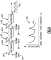
- thermal energy is input into the ammonia fuel flow 58 and to component fuel flows 60 at intermediate locations between segmented cracker assemblies 94A, 94B and 94C.
- the different segmented cracker assemblies 94A, 94B and 94C allow different heat sources to be utilized to input heat into the ammonia fuel 58 and the component fuel flows 60.
- the different fuel flows can be preferentially routed to vary thermal input into the fuel flow as needed to match cracking efficiencies with engine operation.
- Heat input between segmented cracker assemblies may also reduce the variation of temperature through the cracker (maximum to minimum) as compared to a single cracker unit as depicted in Figure 3 for example, which may be desirable if temperature limits or variation are of concern.
- the disclosed engine and fuel system provide for the advantageous use of ammonia fuel to improve engine efficiency and reduce carbon emission.
- the disclosed systems use advantageous properties of components of an ammonia fuel to improve combustion performance and engine efficiencies.
Landscapes
- Engineering & Computer Science (AREA)
- Chemical & Material Sciences (AREA)
- Combustion & Propulsion (AREA)
- Mechanical Engineering (AREA)
- General Engineering & Computer Science (AREA)
- Organic Chemistry (AREA)
- Health & Medical Sciences (AREA)
- General Health & Medical Sciences (AREA)
- Inorganic Chemistry (AREA)
- Engine Equipment That Uses Special Cycles (AREA)
Description
- A gas turbine engine typically mixes a carbon-based fuel with air within a combustor where it is ignited to generate a high-energy exhaust gas flow. The high-energy exhaust gas flow includes carbon that is eventually exhausted into the environment. Alternative engine structures and fuels may aid in the reduction and/or elimination of carbon emissions. One such alternative fuel is ammonia.
- Turbine engine manufacturers continue to seek further improvements to engine performance including improvements to reduce environmental impact while improving propulsive efficiencies.
-
WO 2020189566 A1 describes an ammonia decomposition facility is equipped with: a heating medium line through which a heating medium that is heated with heat generated in a gas turbine flows; an ammonia feeding line through which ammonia flows; an ammonia decomposition device; and an ammonia removal device. -
EP 3540197 A1 a gas turbine plant is provided with a gas turbine, a heating device, a decomposition gas line, and a decomposition gas compressor. The heating device heats ammonia and thermally decomposes the ammonia to convert the ammonia into decomposition gas (PG) including hydrogen gas and nitrogen gas. -
EP 3517757 A1 describes a method for operating a power device, the power device comprises a gas turbine and an exhaust gas system for treatment of exhaust gas, wherein the gas turbine comprises a combustion chamber and a turbine. -
DE 102015213930 A1 describes a gas turbine power plant for generating useful energy, preferably electrical energy, with a gas turbine which has a compressor, a combustion chamber and a turbine on a shaft and which can be charged with a process gas , which is capable of reacting with air to release energy. - According to an aspect of the disclosure, there is provided a gas turbine engine as recited in claim 1.
- In a further embodiment of the foregoing, the gas turbine engine further includes a pump that is configured to increase a pressure of the ammonia flow to a pressure above 5 atm (74 psi) at the cracking device.
- In a further embodiment of the foregoing, the ammonia flow is communicated to the cracking device at a pressure between 5 atm (74 psi) and 300 atm (4410 psi).
- In a further embodiment of the foregoing, the ammonia flow is heated to a temperature at a temperature between 500 °C (935 °F) and 700 °C (1292 °F).
- In a further embodiment of the foregoing, the ammonia flow is heated to a temperature at a temperature above 700 °C (1292 °F).
- In a further embodiment of the foregoing, the flow of component parts includes Hydrogen (H2) and Nitrogen (N2).
- In a further embodiment of the foregoing, the compressor heat exchanger includes an exhaust heat exchanger that provides thermal communication between the ammonia flow and exhaust heat from the turbine section.
- In a further embodiment of the foregoing, the compressor heat exchanger that provides thermal communication between the ammonia flow and compressed air from a last stage of the compressor section.
- In a further embodiment of the foregoing, the compressed air from a last stage of the compressor section that is in thermal communication with the ammonia is subsequently in thermal communication with the combustor to provide combustor cooling.
- In a further embodiment of the foregoing, the compressed air from a last stage of the compressor section that is in thermal communication with the ammonia is subsequently in thermal communication with the turbine to provide combustor cooling.
- In a further embodiment of the foregoing, the compressor heat exchanger that provides thermal communication between the ammonia flow and compressor air from an intermediate stage of the compressor section.
- In a further embodiment of the foregoing, a combustor heat exchanger that provides thermal communication from cooling air after it has cooled the combustor.
- In a further embodiment of the foregoing, a combustor heat exchanger that provides thermal communication from cooling air after it has cooled the turbine.
- In a further embodiment of the foregoing, the ammonia flow is heated prior to entering the cracking device.
- In a further embodiment of the foregoing, the ammonia flow is heated in the cracking device.
- In a further embodiment of the foregoing, the gas turbine engine further includes a turboexpander that receives the ammonia flow and the flow of component parts from the cracker. The ammonia flow and the flow of component parts are expanded through the turboexpander to drive a mechanical output.
- According to an aspect of the disclosure, there is provided a method of operating an energy extraction system as recited in claim 14.
- In a further embodiment of the foregoing, the pressure is raised to between 5 atm (74 psi) and 300 atm (4410 psi).
- In a further embodiment of the foregoing, the heat exchanger heats the ammonia to a temperature between 500 °C (935 °F) and 700 °C (1292 °F).
- In a further embodiment of the foregoing, the heat exchanger heats the ammonia flow to a temperature above 700 °C (1292 °F).
- Although the different examples have the specific components shown in the illustrations, embodiments of this invention are not limited to those particular combinations.
- These and other features disclosed herein can be best understood from the following specification and drawings, the following of which is a brief description.
-
-
Figure 1 is a schematic view of an example gas turbine engine embodiment. -
Figure 2 is a graph illustrating a conversion percentage for a pressure or a temperature. -
Figure 3 is a schematic view of an example cracker assembly embodiment. -
Figure 4 is a schematic view of another example cracker assembly embodiment. -
Figure 5 is a schematic view of yet another example cracker assembly embodiment. -
Figure 1 schematically illustrates an example alternate fueledturbine engine assembly 40. Theengine assembly 40 uses an ammonia-basedfuel flow 60 mixed with acore gas flow 62 in acombustor 46 to generate a highenergy gas flow 64 that expands through aturbine section 48 to drive acompressor section 44. It should be appreciated, that theengine 40 is shown schematically and that other structures and engine configurations such as 2-spool, 3-spool and geared turbofan engines would benefit from this disclosure and are within the contemplation and scope of this disclosure. Moreover, a land-based turbine engine would also benefit from application of the features of this disclosure. The disclosed ammonia-based fuel comprises decomposition products of ammonia (NH3) and/or a mixture of ammonia (NH3) and the decomposition products provided by afuel system 42. - Ammonia (NH3) does not contain carbon, but does have a fuel energy similar to alcohols such as methanol. Ammonia can also be transported and stored in liquid form at moderate pressure and temperature. For example, ammonia is a liquid at a pressure of about 8.5 atm (125 psi) and a temperature of 20 °C (68 °F). Alternatively, ammonia is a liquid at a pressure of 1 atm and a temperature of -33 °C (-27 °F). Moreover, because ammonia does not contain carbon it may be heated to temperatures above that of a hydrocarbon fuel without forming carbon deposits on portions of a fuel system. The increased temperature capabilities of ammonia provide an increased heat sink capacity that can improve engine efficiency. Ammonia can be decomposed into hydrogen and nitrogen component parts. Hydrogen provides improved combustion properties and a desirable clean burning fuel that does not generate undesirable exhaust products. Additionally, removal of nitrogen from the ammonia can reduce nitrous oxide emissions.
- The disclosed
fuel system 42 uses heat to decompose a flow ofammonia fuel 58 into mostly component parts of hydrogen and nitrogen. The component parts of hydrogen and nitrogen along with residual ammonia are communicated to thecombustor 46 to produce the highenergy gas flow 64. - The
ammonia fuel 58 is stored in afuel storage tank 66 and pressurized by afuel pump 68 to a higher level for communication into thecombustor 46. The pressurizedammonia fuel flow 58 is communicated to acracker assembly 70 for decomposition into the component parts of hydrogen and nitrogen. The decomposition process utilizes thermal energy that is drawn from locations on theengine 40. - Referring to
Figure 2 , with continued reference toFigure 1 , the decomposition or conversion process of ammonia into component parts of hydrogen and nitrogen can reach an equilibrium point shown at 22 based on a temperature indicated at 24 and pressure indicated bylines cracker assembly 70 as indicated at 32. The percentage of ammonia converted into component parts at pressures around 1 atm (14 psi) can approach 100% at temperatures above around 300 °C (572 °F). However, higher pressures are needed to communicate the components of the fuel into thecombustor 46. - The degree of conversion decreases as the pressure of the ammonia fuel increases, as is shown by
graph 20. At pressures of around 68 atm (1000 psi), the degree of conversion is reduced to below 70% at 400 °C as is indicated at 30. The degree of conversion at the same pressure increases with an increase in temperature. In this example, the conversion increases to over 80% at temperatures above around 500 °C. Higher pressures require higher temperatures to achieve conversions above 80%. At a pressure of 136 atm (2000 psi), the temperature needed to achieve 80% conversion exceeds 500 °C (932 °F) as indicated byline 28. At a pressure of 272 atm (4000 psi), indicated byline 26, the temperature needed to achieve 80% conversion exceeds 600 °C (1112 °F). Theexample fuel system 42 uses thermal energy from theengine 40 to elevate the temperature of the ammonia fuel flow in view of the pressure required to generate the desired degree of decomposition. - Thermal energy is drawn from various heat sources including heat producing engine systems as is schematically shown at 78, 80 and 82 in
Figure 1 . The heat drawn from the various heat sources is communicated to thecracker assembly 70 as is indicated byarrows 84 to aid and encourage the cracking and decomposition process. - In the disclosed example embodiment, heat is drawn from at least one of several locations within the
engine assembly 40. Heat from each location is communicated through a thermal transfer device such as schematically shownheat exchangers heat exchanger 52 draws heat from thecore airflow 62 after an intermediate or final stage of thecompressor section 44, and may draw heat from all or a portion of the core airflow. Cooled air exitingheat exchanger 52 is delivered as cooling air to engine components such as the combustor or turbine, or to portions of these components. Theheat exchanger 54 draws heat from cooling airflow that has been heated after being used to cool portions of thecombustor 46 and theturbine section 48. Cooling airflow accepts heat fromcombustor 46 and parts of theturbine section 48 and therefore becomes heated. At least a portion of this now heated cooling airflow is utilized to heat theammonia fuel flow 58. Theheat exchanger 56 draws thermal energy from gases exiting an intermediate or final stage of the turbine, or from gases exhausted through anozzle 50. - The
heat exchangers ammonia fuel flow 58. The heat exchangers may be integral with one or more engine components; for example, ammonia may pass through a turbine vane to cool the vane and extract heat from the core flow. Theexample heat exchangers ammonia fuel 58. Moreover, although several example heat source locations are disclosed by way of example, other heat source locations within theengine 40 could be utilized and are within the contemplation of this disclosure. - The
cracker assembly 70 uses theheat 84 communicated from theexample heat sources ammonia fuel flow 58. The higher heat energy aids decomposition of theammonia fuel flow 58 depending on the pressure. The catalyst may be a nickel and/or nickel alloy material, iron, ruthenium, or any other catalytic material that provides for the decomposition of ammonia. The decomposition of the ammonia fuel into hydrogen and nitrogen occurs according to the chemical equation:
NH3 → ½N2 + 3(½H2)
- Depending upon the final temperature and pressure and the rate of decomposition in the presence of a catalyst, all of the ammonia or some portion of the ammonia may become cracked to form nitrogen and hydrogen. In one example embodiment, the
ammonia fuel flow 58 is elevated to a temperature above 500 °C (932 °F) either before the crackingassembly 70 or within the crackingassembly 70. In another disclosed embodiment, theammonia fuel flow 58 is elevated to a temperature between 500 °C (932 °F) and 700 °C (1292 °F) either before the crackingassembly 70 or within the crackingassembly 70. In still another disclosed embodiment, theammonia fuel flow 58 is elevated to a temperature above 700 °C (1292 °F) either before the crackingassembly 70 or within the crackingassembly 70. It should be understood that the above temperatures are provided as examples and that other temperature ranges could be utilized within the contemplation of this disclosure. The example temperatures provide for cracking of theammonia fuel flow 58 into component parts of hydrogen and nitrogen at levels that provide desired combustion properties and performance. - The
pump 68 elevates pressure of theammonia fuel 58 for communication to thecombustor 46. The pressure of theammonia fuel 58 can be adjusted depending on engine operating conditions and available thermal energy to provide desired combustor operation. In one disclosed embodiment, theammonia fuel 58 is pressurized to at least 5 atm (74 psi) at the crackingdevice 70. In another disclosed embodiment, the ammonia fuel is pressurized to between 5 atm (73 psi) and 300 atm (4410 psi) at the crackingdevice 70. The pressure of theammonia fuel flow 58 may be more prior to entering the crackingdevice 70 to accommodate pressure drops encountered within thecracker assembly 70, or in other components between the cracker and the combustor such as a turbo-expander. Moreover, the pressure within the crackingassembly 70 may be higher or different to provide a desired final pressure of thecomponent fuel flow 60 for communication into thecombustor 46. - Because the cracking process is endothermic, the cracked fuel including hydrogen and nitrogen has increased fuel chemical energy and can therefore provide increased engine work output or thrust output without increased fuel flow and thereby improves engine fuel efficiency. The cracking process is endothermic and therefore additional heat absorption capacity becomes available at a given fuel temperature, thereby providing greater heat absorption before the fuel temperature approaches the temperature of the heat source.
- The cracking process increases the number of moles, with one mole of ammonia NH3 becoming two moles of cracked gas, per NH3 → ½ N2 + 3(½ H2), the resulting cracked gas occupies more volume and can provide more work output.
- A turbo-
expander 72 may be provided to receive a portion of thecomponent fuel flow 60 to utilize the increased volume and energy provided in the crackedcomponent fuel flow 60. In this disclosed example, theturbo expander 72 drives a mechanical output in the form of a shaft 74 that drives anengine accessory device 76. The engine accessory device can be an oil pump, generator and/or hydraulic pump as well as any other accessory component utilized to support engine or aircraft operation. Because the cracked gas is less dense and has a higher specific heat capacity it can produce more work as enthalpy is extracted during turbo-expansion. - Furthermore, the cracking process changes the chemical composition of the ammonia fuel and thereby also changes its vapor-liquid equilibrium properties providing greater turbo-expansion of the cracked gas. As appreciated, for a given pressure, the saturation temperature, where vapor begins to condense to liquid, is much lower for H2 and N2 than it is for NH3. As a result, the conversion of some or all of the NH3 to H2 and N2 allows a larger temperature drop and more work extraction across the turbo-
expander 72 without crossing the vapor-liquid equilibrium line than would be possible with pure NH3 as the working fluid in the turbo-expander. - Thermal energy can be added to the ammonia fuel to aid cracking in different manners within the contemplation of this disclosure. Referring to
Figure 3 , in one disclosed example,thermal energy 84 is input into theammonia fuel flow 58 prior to entering thecracker 86. Without further heat addition in the cracker, a temperature gradient of the fuel flow through thecracker assembly 86 decreases with an axial distance from the inlet of thecracker assembly 86 as endothermic cracking progresses, as shown bygraph 88. Accordingly, the initial input temperature may be elevated to such a degree that the fuel achieves and maintains a minimum temperature upon being communicated away from thecracker assembly 86 as thecomponent fuel flow 60. - Referring to
Figure 4 , thermal energy is input into thecracker assembly 90 to provide a constant temperature as shown bygraph 92. In this example thecracker assembly 90 may be combined with a heat exchanger to provide more direct thermal communication between the heat source and the ammonia fuel flow. - Referring to
Figure 5 , thermal energy is input into theammonia fuel flow 58 and to component fuel flows 60 at intermediate locations betweensegmented cracker assemblies 94A, 94B and 94C. In this example, the differentsegmented cracker assemblies 94A, 94B and 94C allow different heat sources to be utilized to input heat into theammonia fuel 58 and the component fuel flows 60. Moreover, the different fuel flows can be preferentially routed to vary thermal input into the fuel flow as needed to match cracking efficiencies with engine operation. Heat input between segmented cracker assemblies may also reduce the variation of temperature through the cracker (maximum to minimum) as compared to a single cracker unit as depicted inFigure 3 for example, which may be desirable if temperature limits or variation are of concern. - The disclosed engine and fuel system provide for the advantageous use of ammonia fuel to improve engine efficiency and reduce carbon emission. The disclosed systems use advantageous properties of components of an ammonia fuel to improve combustion performance and engine efficiencies.
- Although an example embodiment has been disclosed, a worker of ordinary skill in this art would recognize that certain modifications would come within the scope of this disclosure. For that reason, the following claims should be studied to determine the scope and content of this disclosure.
Claims (15)
- A gas turbine engine comprising:a cracking device (70) configured to decompose a portion of an ammonia flow into a flow of component parts of the ammonia flow;a compressor heat exchanger (52) configured to heat the ammonia flow to a temperature above 500 °C (932 °F);a combustor (46) configured to receive and combust the flow of component parts of the ammonia flow to generate a high energy gas flow (64);a compressor section (44) configured to supply compressed air to the combustor (46), wherein the compressor heat exchanger (52) draws heat from a core airflow after an intermediate stage of the compressor section (44) to heat the ammonia flow; anda turbine section (48) in flow communication with the high energy gas flow (64) produced by the combustor (46) and mechanically coupled to drive the compressor section (44), wherein the core airflow from the compressor heat exchanger (52) is delivered to cool at least one of the combustor (46) and/or turbine section (48).
- The gas turbine engine as recited in claim 1, further comprising a pump (68) configured to increase a pressure of the ammonia flow to a pressure above 5 atm (74 psi) at the cracking device (70).
- The gas turbine engine as recited in claim 1 or 2, wherein the ammonia flow is communicated to the cracking device (70) at a pressure between 5 atm (74 psi) and 300 atm (4410 psi).
- The gas turbine engine as recited in claim 1, 2 or 3, wherein the ammonia flow is heated to a temperature at a temperature between 500 °C (935 °F) and 700 °C (1292 °F), or
wherein the ammonia flow is heated to a temperature at a temperature above 700 °C (1292 °F). - The gas turbine engine as recited in in any preceding claim, wherein the flow of component parts comprises Hydrogen (H2) and Nitrogen (N2).
- The gas turbine engine as recited in any preceding claim, wherein the compressor heat exchanger (52) comprises an exhaust heat exchanger providing thermal communication between the ammonia flow and exhaust heat from the turbine section (48).
- The gas turbine engine as recited in any preceding claim, wherein the compressor heat exchanger (52) provides thermal communication between the ammonia flow and compressed air from a last stage of the compressor section (44).
- The gas turbine engine as recited in claim 7, wherein the compressed air from a last stage of the compressor section (44) that is in thermal communication with the ammonia is subsequently in thermal communication with the combustor (46) to provide combustor cooling.
- The gas turbine engine as recited in claim 7 or 8, wherein the compressed air from a last stage of the compressor section (44) that is in thermal communication with the ammonia is subsequently in thermal communication with the turbine to provide turbine cooling.
- The gas turbine engine as recited in any preceding claim, wherein the compressor heat exchanger (52) provides thermal communication between the ammonia flow and compressor air from an intermediate stage of the compressor section (44).
- The gas turbine engine as recited in any preceding claim, wherein a combustor heat exchanger provides thermal communication from cooling air after it has cooled the combustor (46), and/or
wherein the a turbine heat exchanger provides thermal communication from cooling air after it has cooled the turbine. - The gas turbine engine as recited in any preceding claim, wherein the ammonia flow is heated prior to entering the cracking device (70), and/or
wherein the ammonia flow is heated in the cracking device (70). - The gas turbine engine as recited in any preceding claim, further comprising a turboexpander receiving a portion of the ammonia flow and the flow of component parts from the cracker, wherein the portion of the ammonia flow and the flow of component parts are expanded through the turboexpander to drive a mechanical output.
- A method of operating an energy extraction system, comprising:raising a pressure of an ammonia flow to a pressure above 5 atm (74 psi);heating the ammonia flow to a temperature above 500 °C (932 °F) with a heat from a core airflow after an intermediate stage of a compressor section (44) within a compressor heat exchanger (52);decomposing the ammonia fuel flow with a cracking device (70) into a flow containing more Hydrogen (H2) and Nitrogen (N2) than ammonia (NH3);communicating the flow containing more H2 and N2 to a combustor (46) configured to generate a high energy gas flow (64); anddelivering the core airflow from the compressor heat exchanger (52) to cool at least one of the combustor (46) and/or a turbine section (48).
- The method as recited in claim 14, wherein the pressure is raised to between 5 atm (74 psi) and 300 atm (4410 psi), and/orwherein the compressor heat exchanger (52) heats the ammonia to a temperature between 500 °C (935 °F) and 700 °C (1292 °F), orwherein the compressor heat exchanger (52) heats the ammonia flow to a temperature above 700 °C (1292 °F).
Priority Applications (1)
| Application Number | Priority Date | Filing Date | Title |
|---|---|---|---|
| EP24214664.5A EP4488500A3 (en) | 2020-11-20 | 2021-11-19 | Engine using cracked ammonia fuel |
Applications Claiming Priority (1)
| Application Number | Priority Date | Filing Date | Title |
|---|---|---|---|
| US16/953,661 US20220162989A1 (en) | 2020-11-20 | 2020-11-20 | Engine using cracked ammonia fuel |
Related Child Applications (2)
| Application Number | Title | Priority Date | Filing Date |
|---|---|---|---|
| EP24214664.5A Division EP4488500A3 (en) | 2020-11-20 | 2021-11-19 | Engine using cracked ammonia fuel |
| EP24214664.5A Division-Into EP4488500A3 (en) | 2020-11-20 | 2021-11-19 | Engine using cracked ammonia fuel |
Publications (3)
| Publication Number | Publication Date |
|---|---|
| EP4001617A2 EP4001617A2 (en) | 2022-05-25 |
| EP4001617A3 EP4001617A3 (en) | 2022-08-10 |
| EP4001617B1 true EP4001617B1 (en) | 2025-01-01 |
Family
ID=78709366
Family Applications (2)
| Application Number | Title | Priority Date | Filing Date |
|---|---|---|---|
| EP21209410.6A Active EP4001617B1 (en) | 2020-11-20 | 2021-11-19 | Engine using cracked ammonia fuel |
| EP24214664.5A Pending EP4488500A3 (en) | 2020-11-20 | 2021-11-19 | Engine using cracked ammonia fuel |
Family Applications After (1)
| Application Number | Title | Priority Date | Filing Date |
|---|---|---|---|
| EP24214664.5A Pending EP4488500A3 (en) | 2020-11-20 | 2021-11-19 | Engine using cracked ammonia fuel |
Country Status (2)
| Country | Link |
|---|---|
| US (2) | US20220162989A1 (en) |
| EP (2) | EP4001617B1 (en) |
Families Citing this family (26)
| Publication number | Priority date | Publication date | Assignee | Title |
|---|---|---|---|---|
| US11773777B2 (en) * | 2020-12-18 | 2023-10-03 | New Wave Hydrogen, Inc. | Zero-emission jet engine employing a dual-fuel mix of ammonia and hydrogen using a wave |
| US11724245B2 (en) | 2021-08-13 | 2023-08-15 | Amogy Inc. | Integrated heat exchanger reactors for renewable fuel delivery systems |
| US11994061B2 (en) | 2021-05-14 | 2024-05-28 | Amogy Inc. | Methods for reforming ammonia |
| JP2024521417A (en) | 2021-06-11 | 2024-05-31 | アモジー インコーポレイテッド | Systems and methods for processing ammonia |
| GB2608643B (en) * | 2021-07-09 | 2025-01-08 | Reaction Engines Ltd | Thermally integrated ammonia fuelled engine |
| JP7548442B2 (en) * | 2021-07-14 | 2024-09-10 | 株式会社Ihi | Gas Turbine Systems |
| US11539063B1 (en) | 2021-08-17 | 2022-12-27 | Amogy Inc. | Systems and methods for processing hydrogen |
| KR102538689B1 (en) * | 2022-02-15 | 2023-05-30 | 두산에너빌리티 주식회사 | Combined power plant and operating method of the same |
| GB202210681D0 (en) | 2022-07-21 | 2022-09-07 | Johnson Matthey Plc | Process |
| KR20250053118A (en) * | 2022-08-18 | 2025-04-21 | 레르 리키드 쏘시에떼 아노님 뿌르 레뜌드 에렉스뿔라따시옹 데 프로세데 조르즈 클로드 | Method of heating a reformer with an ammonia combustion burner producing a stable flame |
| CN115324668A (en) * | 2022-08-25 | 2022-11-11 | 哈尔滨工业大学 | Ammonia decomposition synthesis gas power generation system |
| US11834334B1 (en) | 2022-10-06 | 2023-12-05 | Amogy Inc. | Systems and methods of processing ammonia |
| CN115585061B (en) * | 2022-10-18 | 2023-06-02 | 南京工程学院 | All-weather cold-heat-power poly-generation system and method based on ammonia synthesis and cracking |
| US11866328B1 (en) | 2022-10-21 | 2024-01-09 | Amogy Inc. | Systems and methods for processing ammonia |
| US11795055B1 (en) | 2022-10-21 | 2023-10-24 | Amogy Inc. | Systems and methods for processing ammonia |
| US12116956B2 (en) | 2022-12-13 | 2024-10-15 | General Electric Company | Ammonia based hydrogen powered combined propulsion system |
| US12264621B2 (en) * | 2023-05-30 | 2025-04-01 | Doosan Enerbility Co., Ltd. | Gas turbine plant with ammonia decomposition system |
| US12385433B2 (en) * | 2023-05-30 | 2025-08-12 | Doosan Enerbility Co., Ltd. | Gas turbine plant with ammonia decomposition system |
| KR20240171446A (en) | 2023-05-30 | 2024-12-09 | 두산에너빌리티 주식회사 | Gas turbine plant with ammonia decomposition system |
| KR102897162B1 (en) * | 2023-05-30 | 2025-12-09 | 두산에너빌리티 주식회사 | Gas turbine plant with ammonia decomposition system |
| KR102897161B1 (en) | 2023-05-30 | 2025-12-09 | 두산에너빌리티 주식회사 | Gas turbine plant with ammonia decomposition system |
| KR102921605B1 (en) | 2023-05-30 | 2026-02-02 | 두산에너빌리티 주식회사 | Gas turbine plant with ammonia decomposition system |
| GB2630767A (en) * | 2023-06-07 | 2024-12-11 | Siemens Energy Global Gmbh & Co Kg | Gas turbine arrangement with ammonia cracker and power plant with such and method to operate a gas turbine arrangement |
| US12552419B2 (en) * | 2023-10-31 | 2026-02-17 | Cummins Power Generation Inc. | Ammonia cracking for multi-fuel engines |
| GB202405155D0 (en) | 2024-04-11 | 2024-05-29 | Johnson Matthey Plc | Process and plant |
| US12467403B1 (en) | 2024-06-28 | 2025-11-11 | Pratt & Whitney Canada Corp. | Powerplant fuel system utilizing ammonia |
Family Cites Families (12)
| Publication number | Priority date | Publication date | Assignee | Title |
|---|---|---|---|---|
| WO2002008117A1 (en) * | 2000-07-25 | 2002-01-31 | Apollo Energy Systems, Incorporated | Ammonia cracker for production of hydrogen |
| US8220268B2 (en) * | 2007-11-28 | 2012-07-17 | Caterpillar Inc. | Turbine engine having fuel-cooled air intercooling |
| US8943826B2 (en) * | 2009-01-14 | 2015-02-03 | Toyota Jidosha Kabushiki Kaisha | Engine |
| WO2012045028A1 (en) * | 2010-09-30 | 2012-04-05 | General Electric Company | Dual fuel aircraft system and method for operating same |
| DE102015213930A1 (en) * | 2015-07-23 | 2017-01-26 | Siemens Aktiengesellschaft | Gas turbine power plant |
| ES2963067T3 (en) * | 2016-03-14 | 2024-03-25 | Equinor Energy As | Ammonia cracking |
| JP6707013B2 (en) * | 2016-11-08 | 2020-06-10 | 三菱日立パワーシステムズ株式会社 | Gas turbine plant and operating method thereof |
| JP6772925B2 (en) * | 2017-03-27 | 2020-10-21 | 株式会社Ihi | Combustion equipment and gas turbine engine system |
| JP6880902B2 (en) * | 2017-03-27 | 2021-06-02 | 株式会社Ihi | gas turbine |
| EP3517757A1 (en) * | 2018-01-30 | 2019-07-31 | Siemens Aktiengesellschaft | Method for operating a power device and power device |
| US11047307B2 (en) * | 2018-09-14 | 2021-06-29 | Raytheon Technologies Corporation | Hybrid expander cycle with intercooling and turbo-generator |
| JP7285098B2 (en) * | 2019-03-15 | 2023-06-01 | 三菱重工業株式会社 | Ammonia decomposition equipment, gas turbine plant equipped with same, ammonia decomposition method |
-
2020
- 2020-11-20 US US16/953,661 patent/US20220162989A1/en not_active Abandoned
-
2021
- 2021-11-19 EP EP21209410.6A patent/EP4001617B1/en active Active
- 2021-11-19 EP EP24214664.5A patent/EP4488500A3/en active Pending
-
2022
- 2022-12-21 US US18/086,023 patent/US20230129294A1/en not_active Abandoned
Also Published As
| Publication number | Publication date |
|---|---|
| US20230129294A1 (en) | 2023-04-27 |
| US20220162989A1 (en) | 2022-05-26 |
| EP4488500A3 (en) | 2025-03-12 |
| EP4488500A2 (en) | 2025-01-08 |
| EP4001617A2 (en) | 2022-05-25 |
| EP4001617A3 (en) | 2022-08-10 |
Similar Documents
| Publication | Publication Date | Title |
|---|---|---|
| EP4001617B1 (en) | Engine using cracked ammonia fuel | |
| US12473856B2 (en) | Cracking and separation of ammonia fuel | |
| EP3943732B1 (en) | Engine using heated and turbo-expanded ammonia fuel | |
| EP4063629B1 (en) | Turboexpander inter-stage heating and nh3 cracking | |
| EP4253739A1 (en) | Efficient turbine engine using integrated ammonia fuel processing | |
| JP6189500B2 (en) | System and method for high efficiency power generation using nitrogen gas working fluid | |
| KR102536353B1 (en) | Combined power plant and operating method of the same | |
| US20050210879A1 (en) | Pulse detonation engine system for driving turbine | |
| JP2016510278A (en) | Aircraft and method for managing evaporated cryogenic fuel | |
| KR102538689B1 (en) | Combined power plant and operating method of the same | |
| JP2016508912A (en) | Method for managing LNG boil-off and management assembly for LNG boil-off | |
| US12092021B2 (en) | Hydrogen hybrid cycle system | |
| EP1795805A2 (en) | Rich catalytic clean burn for liquid fuel with fuel stabilization unit | |
| WO2019032755A1 (en) | Hydrogen hybrid cycle system | |
| US12215623B1 (en) | Partial exhaust bottoming cycle | |
| KR102748819B1 (en) | Combined power plant and operating method of the same | |
| KR20250124367A (en) | Gas turbine auxiliary system for NH₃ conditioning | |
| US9200596B2 (en) | Catalytically enhanced gas generator system for rocket applications | |
| KR102767234B1 (en) | Combined power plant and operating method of the same | |
| US20260015969A1 (en) | Fuel cell exhaust condensation with turbomachinery water augmentation using cryogenic bottoming cycle | |
| KR102921605B1 (en) | Gas turbine plant with ammonia decomposition system | |
| RU2444637C2 (en) | Energy generation method |
Legal Events
| Date | Code | Title | Description |
|---|---|---|---|
| PUAI | Public reference made under article 153(3) epc to a published international application that has entered the european phase |
Free format text: ORIGINAL CODE: 0009012 |
|
| STAA | Information on the status of an ep patent application or granted ep patent |
Free format text: STATUS: THE APPLICATION HAS BEEN PUBLISHED |
|
| AK | Designated contracting states |
Kind code of ref document: A2 Designated state(s): AL AT BE BG CH CY CZ DE DK EE ES FI FR GB GR HR HU IE IS IT LI LT LU LV MC MK MT NL NO PL PT RO RS SE SI SK SM TR |
|
| PUAL | Search report despatched |
Free format text: ORIGINAL CODE: 0009013 |
|
| AK | Designated contracting states |
Kind code of ref document: A3 Designated state(s): AL AT BE BG CH CY CZ DE DK EE ES FI FR GB GR HR HU IE IS IT LI LT LU LV MC MK MT NL NO PL PT RO RS SE SI SK SM TR |
|
| RIC1 | Information provided on ipc code assigned before grant |
Ipc: F02C 7/224 20060101AFI20220701BHEP |
|
| STAA | Information on the status of an ep patent application or granted ep patent |
Free format text: STATUS: REQUEST FOR EXAMINATION WAS MADE |
|
| 17P | Request for examination filed |
Effective date: 20230210 |
|
| RBV | Designated contracting states (corrected) |
Designated state(s): AL AT BE BG CH CY CZ DE DK EE ES FI FR GB GR HR HU IE IS IT LI LT LU LV MC MK MT NL NO PL PT RO RS SE SI SK SM TR |
|
| RAP3 | Party data changed (applicant data changed or rights of an application transferred) |
Owner name: RTX CORPORATION |
|
| GRAP | Despatch of communication of intention to grant a patent |
Free format text: ORIGINAL CODE: EPIDOSNIGR1 |
|
| STAA | Information on the status of an ep patent application or granted ep patent |
Free format text: STATUS: GRANT OF PATENT IS INTENDED |
|
| INTG | Intention to grant announced |
Effective date: 20240723 |
|
| GRAS | Grant fee paid |
Free format text: ORIGINAL CODE: EPIDOSNIGR3 |
|
| GRAA | (expected) grant |
Free format text: ORIGINAL CODE: 0009210 |
|
| STAA | Information on the status of an ep patent application or granted ep patent |
Free format text: STATUS: THE PATENT HAS BEEN GRANTED |
|
| AK | Designated contracting states |
Kind code of ref document: B1 Designated state(s): AL AT BE BG CH CY CZ DE DK EE ES FI FR GB GR HR HU IE IS IT LI LT LU LV MC MK MT NL NO PL PT RO RS SE SI SK SM TR |
|
| REG | Reference to a national code |
Ref country code: GB Ref legal event code: FG4D |
|
| REG | Reference to a national code |
Ref country code: CH Ref legal event code: EP |
|
| REG | Reference to a national code |
Ref country code: DE Ref legal event code: R096 Ref document number: 602021024193 Country of ref document: DE |
|
| REG | Reference to a national code |
Ref country code: IE Ref legal event code: FG4D |
|
| REG | Reference to a national code |
Ref country code: LT Ref legal event code: MG9D |
|
| REG | Reference to a national code |
Ref country code: NL Ref legal event code: MP Effective date: 20250101 |
|
| REG | Reference to a national code |
Ref country code: AT Ref legal event code: MK05 Ref document number: 1756460 Country of ref document: AT Kind code of ref document: T Effective date: 20250101 |
|
| PG25 | Lapsed in a contracting state [announced via postgrant information from national office to epo] |
Ref country code: NL Free format text: LAPSE BECAUSE OF FAILURE TO SUBMIT A TRANSLATION OF THE DESCRIPTION OR TO PAY THE FEE WITHIN THE PRESCRIBED TIME-LIMIT Effective date: 20250101 |
|
| PG25 | Lapsed in a contracting state [announced via postgrant information from national office to epo] |
Ref country code: FI Free format text: LAPSE BECAUSE OF FAILURE TO SUBMIT A TRANSLATION OF THE DESCRIPTION OR TO PAY THE FEE WITHIN THE PRESCRIBED TIME-LIMIT Effective date: 20250101 |
|
| PG25 | Lapsed in a contracting state [announced via postgrant information from national office to epo] |
Ref country code: PL Free format text: LAPSE BECAUSE OF FAILURE TO SUBMIT A TRANSLATION OF THE DESCRIPTION OR TO PAY THE FEE WITHIN THE PRESCRIBED TIME-LIMIT Effective date: 20250101 |
|
| PG25 | Lapsed in a contracting state [announced via postgrant information from national office to epo] |
Ref country code: ES Free format text: LAPSE BECAUSE OF FAILURE TO SUBMIT A TRANSLATION OF THE DESCRIPTION OR TO PAY THE FEE WITHIN THE PRESCRIBED TIME-LIMIT Effective date: 20250101 |
|
| PG25 | Lapsed in a contracting state [announced via postgrant information from national office to epo] |
Ref country code: IS Free format text: LAPSE BECAUSE OF FAILURE TO SUBMIT A TRANSLATION OF THE DESCRIPTION OR TO PAY THE FEE WITHIN THE PRESCRIBED TIME-LIMIT Effective date: 20250501 Ref country code: NO Free format text: LAPSE BECAUSE OF FAILURE TO SUBMIT A TRANSLATION OF THE DESCRIPTION OR TO PAY THE FEE WITHIN THE PRESCRIBED TIME-LIMIT Effective date: 20250401 |
|
| PG25 | Lapsed in a contracting state [announced via postgrant information from national office to epo] |
Ref country code: HR Free format text: LAPSE BECAUSE OF FAILURE TO SUBMIT A TRANSLATION OF THE DESCRIPTION OR TO PAY THE FEE WITHIN THE PRESCRIBED TIME-LIMIT Effective date: 20250101 |
|
| PG25 | Lapsed in a contracting state [announced via postgrant information from national office to epo] |
Ref country code: PT Free format text: LAPSE BECAUSE OF FAILURE TO SUBMIT A TRANSLATION OF THE DESCRIPTION OR TO PAY THE FEE WITHIN THE PRESCRIBED TIME-LIMIT Effective date: 20250502 Ref country code: LV Free format text: LAPSE BECAUSE OF FAILURE TO SUBMIT A TRANSLATION OF THE DESCRIPTION OR TO PAY THE FEE WITHIN THE PRESCRIBED TIME-LIMIT Effective date: 20250101 |
|
| PG25 | Lapsed in a contracting state [announced via postgrant information from national office to epo] |
Ref country code: GR Free format text: LAPSE BECAUSE OF FAILURE TO SUBMIT A TRANSLATION OF THE DESCRIPTION OR TO PAY THE FEE WITHIN THE PRESCRIBED TIME-LIMIT Effective date: 20250402 Ref country code: BG Free format text: LAPSE BECAUSE OF FAILURE TO SUBMIT A TRANSLATION OF THE DESCRIPTION OR TO PAY THE FEE WITHIN THE PRESCRIBED TIME-LIMIT Effective date: 20250101 |
|
| PG25 | Lapsed in a contracting state [announced via postgrant information from national office to epo] |
Ref country code: AT Free format text: LAPSE BECAUSE OF FAILURE TO SUBMIT A TRANSLATION OF THE DESCRIPTION OR TO PAY THE FEE WITHIN THE PRESCRIBED TIME-LIMIT Effective date: 20250101 |
|
| PG25 | Lapsed in a contracting state [announced via postgrant information from national office to epo] |
Ref country code: CZ Free format text: LAPSE BECAUSE OF FAILURE TO SUBMIT A TRANSLATION OF THE DESCRIPTION OR TO PAY THE FEE WITHIN THE PRESCRIBED TIME-LIMIT Effective date: 20250101 |
|
| PG25 | Lapsed in a contracting state [announced via postgrant information from national office to epo] |
Ref country code: SE Free format text: LAPSE BECAUSE OF FAILURE TO SUBMIT A TRANSLATION OF THE DESCRIPTION OR TO PAY THE FEE WITHIN THE PRESCRIBED TIME-LIMIT Effective date: 20250101 |
|
| REG | Reference to a national code |
Ref country code: DE Ref legal event code: R097 Ref document number: 602021024193 Country of ref document: DE |
|
| PG25 | Lapsed in a contracting state [announced via postgrant information from national office to epo] |
Ref country code: SM Free format text: LAPSE BECAUSE OF FAILURE TO SUBMIT A TRANSLATION OF THE DESCRIPTION OR TO PAY THE FEE WITHIN THE PRESCRIBED TIME-LIMIT Effective date: 20250101 |
|
| PG25 | Lapsed in a contracting state [announced via postgrant information from national office to epo] |
Ref country code: DK Free format text: LAPSE BECAUSE OF FAILURE TO SUBMIT A TRANSLATION OF THE DESCRIPTION OR TO PAY THE FEE WITHIN THE PRESCRIBED TIME-LIMIT Effective date: 20250101 |
|
| PG25 | Lapsed in a contracting state [announced via postgrant information from national office to epo] |
Ref country code: IT Free format text: LAPSE BECAUSE OF FAILURE TO SUBMIT A TRANSLATION OF THE DESCRIPTION OR TO PAY THE FEE WITHIN THE PRESCRIBED TIME-LIMIT Effective date: 20250101 |
|
| PG25 | Lapsed in a contracting state [announced via postgrant information from national office to epo] |
Ref country code: EE Free format text: LAPSE BECAUSE OF FAILURE TO SUBMIT A TRANSLATION OF THE DESCRIPTION OR TO PAY THE FEE WITHIN THE PRESCRIBED TIME-LIMIT Effective date: 20250101 |
|
| PG25 | Lapsed in a contracting state [announced via postgrant information from national office to epo] |
Ref country code: RO Free format text: LAPSE BECAUSE OF FAILURE TO SUBMIT A TRANSLATION OF THE DESCRIPTION OR TO PAY THE FEE WITHIN THE PRESCRIBED TIME-LIMIT Effective date: 20250101 |
|
| PG25 | Lapsed in a contracting state [announced via postgrant information from national office to epo] |
Ref country code: SK Free format text: LAPSE BECAUSE OF FAILURE TO SUBMIT A TRANSLATION OF THE DESCRIPTION OR TO PAY THE FEE WITHIN THE PRESCRIBED TIME-LIMIT Effective date: 20250101 |
|
| PLBE | No opposition filed within time limit |
Free format text: ORIGINAL CODE: 0009261 |
|
| STAA | Information on the status of an ep patent application or granted ep patent |
Free format text: STATUS: NO OPPOSITION FILED WITHIN TIME LIMIT |
|
| 26N | No opposition filed |
Effective date: 20251002 |
|
| PGFP | Annual fee paid to national office [announced via postgrant information from national office to epo] |
Ref country code: DE Payment date: 20251022 Year of fee payment: 5 |
|
| PGFP | Annual fee paid to national office [announced via postgrant information from national office to epo] |
Ref country code: GB Payment date: 20251023 Year of fee payment: 5 |
|
| PGFP | Annual fee paid to national office [announced via postgrant information from national office to epo] |
Ref country code: FR Payment date: 20251022 Year of fee payment: 5 |