EP4001584A1 - Downhole packer assembly - Google Patents
Downhole packer assembly Download PDFInfo
- Publication number
- EP4001584A1 EP4001584A1 EP20209615.2A EP20209615A EP4001584A1 EP 4001584 A1 EP4001584 A1 EP 4001584A1 EP 20209615 A EP20209615 A EP 20209615A EP 4001584 A1 EP4001584 A1 EP 4001584A1
- Authority
- EP
- European Patent Office
- Prior art keywords
- axially movable
- movable part
- downhole
- expandable tubular
- packer assembly
- Prior art date
- Legal status (The legal status is an assumption and is not a legal conclusion. Google has not performed a legal analysis and makes no representation as to the accuracy of the status listed.)
- Withdrawn
Links
Images


Classifications
-
- E—FIXED CONSTRUCTIONS
- E21—EARTH OR ROCK DRILLING; MINING
- E21B—EARTH OR ROCK DRILLING; OBTAINING OIL, GAS, WATER, SOLUBLE OR MELTABLE MATERIALS OR A SLURRY OF MINERALS FROM WELLS
- E21B23/00—Apparatus for displacing, setting, locking, releasing or removing tools, packers or the like in boreholes or wells
- E21B23/14—Apparatus for displacing, setting, locking, releasing or removing tools, packers or the like in boreholes or wells for displacing a cable or a cable-operated tool, e.g. for logging or perforating operations in deviated wells
-
- E—FIXED CONSTRUCTIONS
- E21—EARTH OR ROCK DRILLING; MINING
- E21B—EARTH OR ROCK DRILLING; OBTAINING OIL, GAS, WATER, SOLUBLE OR MELTABLE MATERIALS OR A SLURRY OF MINERALS FROM WELLS
- E21B33/00—Sealing or packing boreholes or wells
- E21B33/10—Sealing or packing boreholes or wells in the borehole
- E21B33/12—Packers; Plugs
- E21B33/127—Packers; Plugs with inflatable sleeve
- E21B33/1277—Packers; Plugs with inflatable sleeve characterised by the construction or fixation of the sleeve
-
- E—FIXED CONSTRUCTIONS
- E21—EARTH OR ROCK DRILLING; MINING
- E21B—EARTH OR ROCK DRILLING; OBTAINING OIL, GAS, WATER, SOLUBLE OR MELTABLE MATERIALS OR A SLURRY OF MINERALS FROM WELLS
- E21B33/00—Sealing or packing boreholes or wells
- E21B33/10—Sealing or packing boreholes or wells in the borehole
- E21B33/12—Packers; Plugs
- E21B33/1208—Packers; Plugs characterised by the construction of the sealing or packing means
- E21B33/1212—Packers; Plugs characterised by the construction of the sealing or packing means including a metal-to-metal seal element
-
- E—FIXED CONSTRUCTIONS
- E21—EARTH OR ROCK DRILLING; MINING
- E21B—EARTH OR ROCK DRILLING; OBTAINING OIL, GAS, WATER, SOLUBLE OR MELTABLE MATERIALS OR A SLURRY OF MINERALS FROM WELLS
- E21B33/00—Sealing or packing boreholes or wells
- E21B33/10—Sealing or packing boreholes or wells in the borehole
- E21B33/12—Packers; Plugs
- E21B33/127—Packers; Plugs with inflatable sleeve
-
- E—FIXED CONSTRUCTIONS
- E21—EARTH OR ROCK DRILLING; MINING
- E21B—EARTH OR ROCK DRILLING; OBTAINING OIL, GAS, WATER, SOLUBLE OR MELTABLE MATERIALS OR A SLURRY OF MINERALS FROM WELLS
- E21B33/00—Sealing or packing boreholes or wells
- E21B33/10—Sealing or packing boreholes or wells in the borehole
- E21B33/12—Packers; Plugs
- E21B33/128—Packers; Plugs with a member expanded radially by axial pressure
-
- E—FIXED CONSTRUCTIONS
- E21—EARTH OR ROCK DRILLING; MINING
- E21B—EARTH OR ROCK DRILLING; OBTAINING OIL, GAS, WATER, SOLUBLE OR MELTABLE MATERIALS OR A SLURRY OF MINERALS FROM WELLS
- E21B41/00—Equipment or details not covered by groups E21B15/00 - E21B40/00
- E21B41/0021—Safety devices, e.g. for preventing small objects from falling into the borehole
-
- E—FIXED CONSTRUCTIONS
- E21—EARTH OR ROCK DRILLING; MINING
- E21B—EARTH OR ROCK DRILLING; OBTAINING OIL, GAS, WATER, SOLUBLE OR MELTABLE MATERIALS OR A SLURRY OF MINERALS FROM WELLS
- E21B43/00—Methods or apparatus for obtaining oil, gas, water, soluble or meltable materials or a slurry of minerals from wells
- E21B43/02—Subsoil filtering
- E21B43/10—Setting of casings, screens, liners or the like in wells
- E21B43/103—Setting of casings, screens, liners or the like in wells of expandable casings, screens, liners, or the like
- E21B43/105—Expanding tools specially adapted therefor
-
- F—MECHANICAL ENGINEERING; LIGHTING; HEATING; WEAPONS; BLASTING
- F16—ENGINEERING ELEMENTS AND UNITS; GENERAL MEASURES FOR PRODUCING AND MAINTAINING EFFECTIVE FUNCTIONING OF MACHINES OR INSTALLATIONS; THERMAL INSULATION IN GENERAL
- F16L—PIPES; JOINTS OR FITTINGS FOR PIPES; SUPPORTS FOR PIPES, CABLES OR PROTECTIVE TUBING; MEANS FOR THERMAL INSULATION IN GENERAL
- F16L55/00—Devices or appurtenances for use in, or in connection with, pipes or pipe systems
- F16L55/16—Devices for covering leaks in pipes or hoses, e.g. hose-menders
- F16L55/162—Devices for covering leaks in pipes or hoses, e.g. hose-menders from inside the pipe
- F16L55/163—Devices for covering leaks in pipes or hoses, e.g. hose-menders from inside the pipe a ring, a band or a sleeve being pressed against the inner surface of the pipe
Definitions
- the present invention relates to a downhole packer assembly for expansion of a metal sleeve, such as a metal patch, in a well downhole in a well tubular metal structure.
- the invention also relates to a downhole system comprising the downhole packer assembly and a driving unit, such as a downhole tractor, for propelling the downhole packer assembly in the well tubular metal structure.
- a downhole packer assembly for expansion of a metal sleeve, such as a metal patch, in a well downhole in a well tubular metal structure, the well having a top comprising:
- the axially movable part may have a length along the axial extension and may overlap the expandable tubular packer element by a distance being more than 10% of the length, preferably more than 25% of the length, even more preferably more than 50% of the length.
- the axially movable part may move from the first position to the second position as the expandable tubular packer element expands and forces the axially movable part away from the expandable tubular packer element.
- first part end of the axially movable part may have an inclined face inclining from an end point radially inwards towards the body part.
- first part end of the axially movable part may have an inclined face facing an outer face of the expandable tubular packer element in the first position.
- first part end of the axially movable part may have an inclined face inclining from an end point radially inwards towards an inner face of the axially movable part.
- the axially movable part may be ring-shaped.
- the expandable tubular packer element may have an outer face having a friction coefficient, the axially movable part being maintained in the first position by friction between the outer face and inner face of the first part of the axially movable part.
- the body part may have a projection increasing the outer diameter of the body part that is larger than an inner diameter of the axially movable part.
- the axially movable part may be maintained in the first position by a shear pin.
- the axially movable part may be maintained in the first position by a snap ring or a spring-loaded element movable in a first groove in the body part and engaging a first indentation in an inner face of the axially movable part.
- the axially movable part may have a second indentation arranged in the inner face of the axially movable part at a distance from the first indentation and closer to the metal sleeve than the first indentation.
- restriction unit may comprise a second part fixedly connected to the body part.
- the second part may have a plurality of second arms having an inner face provided with grooves for engaging an outer face of the body part.
- each second arm may have an outer face inclining away from the axially movable part.
- the second part may comprise a fastening ring for sliding onto the outer face of the second arms, forcing the grooves of the inner face into engagement with the outer face of the body part.
- the second part may be a projection on the body part.
- the second part may be a snap ring or a spring-loaded element movable radially and axially fixated in a first groove in the body part.
- restriction unit may be a first restriction unit.
- the downhole packer assembly may comprise a second restriction unit comprising an axially movable part, the axially movable part having a first part end facing the first end of the expandable tubular packer element and a second part end facing away from the expandable tubular packer element, the axially movable part having a first position in which the axially movable part at least partly overlaps the expandable tubular packer element and a second position in which the axially movable part has been axially displaced in relation to the body part away from the expandable tubular packer element towards the top of the well.
- the axially movable part and/or the second part of the restriction unit may have a base part and extending arms each having an inwardly extending projection.
- the arms may have a thickness smaller than a thickness of the base part.
- the arms may be more flexible than the base part.
- the base part may have openings for screwing the base part to the body part.
- the axially movable part may be ring-shaped, the second part end having an annular projection, and the axially movable part comprising an intermediate section having an outer diameter smaller than that of the annular projection.
- first part end of the axially movable part may have an inclined face facing the metal sleeve.
- the inclined face may correspond to an inclined face at the end of the metal sleeve.
- the axially movable part may have an indentation in an outer face of the axially movable part.
- the present invention relates to a downhole system comprising the downhole packer assembly and a driving unit, such as a downhole tractor, for propelling the downhole packer assembly in the well tubular metal structure.
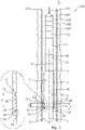
- Fig. 1 shows a downhole packer assembly 1 for expansion of a metal sleeve, such as a metal patch 10, in a well 111 downhole in a well tubular metal structure 103, the well having a top 51.
- the downhole packer assembly 1 comprises a body part 2 having an axial extension L, a first end 8 facing downhole and a second end 9 facing uphole towards the top of the well.
- the downhole packer assembly 1 further comprises an expandable tubular packer element 3 surrounding the body part 2, and a first end 5 and a second end 6 of the expandable tubular packer element 3 are fixedly connected with the body part 2, providing an expandable space 4 therebetween, and the expandable space 4 being fillable with liquid during expansion in order to expand the expandable tubular packer element 3 and a metal sleeve 10 surrounding the expandable tubular packer element 3.
- the downhole packer assembly 1 further comprises a restriction unit (11, 11A) for restricting the expandable tubular packer element 3 from moving along the axial extension or falling off while running the downhole packer assembly 1 into the vertical part of the well tubular metal structure.
- the downhole packer assembly 1 may also bump into restrictions in the well which may force the expandable tubular packer element 3 to move if not restricted from doing so by the restriction unit 11.
- the restriction unit 11 comprises an axially movable part 12 having a first part end 15 facing the first end of the expandable tubular packer element 3 and a second part end 16 facing away from the expandable tubular packer element 3.
- the axially movable part 12 has a first position in which the axially movable part 12 at least partly overlaps and abuts the expandable tubular packer element 3 (as shown in Fig. 2A ) and a second position in which the axially movable part 12 has been axially displaced in relation to the body part 2 away from the expandable tubular packer element 3 (as shown in Fig. 2B ).
- a simple restriction of the metal patch 10 is accomplished so that an unexpanded or partly expanded metal patch 10 is not lost in the well if the power is temporarily lost during conveying the downhole packer assembly 1 in the well tubular metal structure.
- the restriction unit 11 is able to maintain the metal patch 10 in the intended position without restricting the ends of the metal patch 10 from expanding.
- the downhole packer assembly 1 in Fig. 1 also comprises a positive displacement pump 93 for pumping liquid into the expandable space 4 to expand the expandable tubular packer element 3.
- the positive displacement pump 93 is connected to the top via a wireline 104 and a cable head 109.
- the positive displacement pump 93 comprises an electrical control 105.
- the positive displacement pump 93 comprises a motor 106 driving a second pump.
- the positive displacement pump 93 further comprises a compensator 107 for keeping a predetermined overpressure in the positive displacement pump 93 compared to the surrounding pressure.
- the positive displacement pump 93 further comprises a driving means 112 to the movement of a first piston in the pump housing in a first direction or a second direction.
- the positive displacement pump 93 further comprises a discharge control unit 90 having an aperture 91 for discharging fluid in the expandable tubular packer element 3 of the downhole packer assembly 1 in order to deflate the expandable tubular packer element 3.
- the downhole packer assembly 1 is shown in its deflated position.
- the discharge control unit 90 may be a flow-operated discharge control unit 90.
- the axially movable part 12 has a length x along the axial extension L and overlaps the expandable tubular packer element 3 by a distance d (also shown in Fig. 6 ) which is more than 10% of the length x, preferably more than 25% of the length x, and in Fig. 1 more than 50% of the length x.
- d also shown in Fig. 6
- the axially movable part 12 is forced to move from the first position to the second position in that the radial expansion of the expandable tubular packer element 3 forces the axially movable part 12 to slide away from the expandable tubular packer element 3.
- the axially movable part 12 may at least partly overlap an end of the metal sleeve 10, and once the axially movable part 12 slides at least partly off the expandable tubular packer element 3, the axially movable part 12 moves from the first position in which it overlaps the metal sleeve 10 to the second position where the metal sleeve 10 is free to move radially outwards along with the expandable tubular packer element 3.
- the first part end 15 of the axially movable part 12 has an inclined face 22 (also shown in Figs. 5 and 6 ) inclining from an end point 23 radially inwards towards the body part 2.
- the inclined face 22 assists the axially movable part 12 in moving towards the first end 8 of the body part 2 and thus sliding off the expandable tubular packer element 3.
- the axially movable part 12 is ring-shaped, but may have any suitable shape and may be a two-part sleeve which is assembled and fastened around the body part 2 and the expandable tubular packer element 3.
- the axially movable part 12 is maintained in the first position by a snap ring 18 radially movable in a first groove 20 in the body part 2 and engaging a first indentation 25 in an inner face of the axially movable part 12.
- the axially movable part 12 has a second indentation 26 arranged in the inner face of the axially movable part 12 at a distance from the first indentation 25 and closer to the metal sleeve 10 than the first indentation.
- the second indentation 26 engages the snap ring 18 when the axially movable part 12 moves from the first position to the second position, and the axially movable part 12 is thus locked in the second position so that the axially movable part 12 does not slide fully off the body part 2.
- the expandable tubular packer element 3 has an outer face 7 having a friction coefficient, and the axially movable part 12 is maintained in the first position by friction between the outer face and an inner face of the first part of the axially movable part 12.
- the body part 2 has a projection 21 increasing the outer diameter of the body part 2 so that the outer diameter of the projection 21 is larger than an inner diameter of the axially movable part 12, and the projection 21 thus prevents the axially movable part 12 from sliding off the body part 2, as shown in Fig. 2B .
- the body part 2 has two projections 21 arranged at a distance from each of the axially movable parts 12 in the first position in order to prevent the axially movable parts 12 from sliding off the body part 2.
- the downhole packer assembly 1 comprises a first restriction unit 11, 11A in a first end 8 and a second restriction unit 11, 11B in the second end 9.
- Each restriction unit 11 comprises the axially movable part 12, which is maintained in the first position by a shear pin 17.
- the axially movable part 12 may also be maintained in the first position by a spring-loaded element 19, as shown in Fig. 5 , which is movable in a first groove 20 in the body part 2 and engaging a first indentation 25 in an inner face 28 of the axially movable part 12.
- the axially movable part 12 has a second indentation 26 arranged in the inner face 28 of the axially movable part 12 at a distance from the first indentation 25 and closer to the metal sleeve 10 than the first indentation 25.
- the second indentation 26 engages the spring-loaded element 19 when the axially movable part 12 moves from the first position to the second position, and the axially movable part 12 is thus locked in the second position so that the axially movable part 12 does not slide fully off the body part 2.
- the restriction unit 11 further comprises a second part 14 fixedly connected to the body part 2.
- the axially movable part 12 has a base part 30 and an extending arm 31 having an inwardly extending projection 32 for engaging the second part 14 in the form of a projection 21 when the axially movable part 12 moves to the second position away from the metal sleeve 10.
- the second part 14 has a plurality of arms 31 with inwardly extending projections 32 for engaging a projection of the axially movable part 12.
- the base part 30 of the second part 14 has openings 33 for screwing the base part 30 to the body part 2.
- both the axially movable part 12 and the second part of the restriction unit may have a base part 30 and extending arms 31, each having an inwardly extending projection 32, and the other axially movable part and the second part have an engageable projection.
- the arm(s) has a thickness t1 smaller than a thickness t2 of the base part 30.
- the arm(s) is thus made more flexible than the base part 30 so as to be able to bend radially outwards when forced past the projection and to flex inwards again after having passed the projection.
- the second part 14 may be the snap ring 18 (shown in Fig. 6 ) or a spring-loaded element 19 (shown in Fig. 5 ) movable radially and axially fixated in a first groove 20 in the body part 2.
- the restriction unit 11 has an axially movable part 12 abutting the metal sleeve 10 (indicated with a dotted line for illustration purposes), and the second part 14 of the restriction unit 11 has a base part 30 and a plurality of arms 31 with an inwardly extending projection 32 abutting the second part end 16 of the axially movable part 12.
- the base part 30 of the second part 14 is fastened to the body part 2.
- the axially movable part 12 is shown in the first position in Fig. 10A and in its second position in Fig. 10B .
- the axially movable part 12 is ring-shaped, and the second part end 16 thereof has an annular projection 34.
- the axially movable part 12 comprises an intermediate section 35 having an outer diameter OD 1 smaller than that of the annular projection 34.
- the arms have passed the annular projection 34 as the ring-shaped axially movable part 12 has been forced underneath the arms as the expandable tubular packer element 3 expands as shown in Fig. 10B .
- the first part end 15 of the axially movable part 12 has an inclined face 36 facing the metal sleeve 10, and the inclined face 36 corresponds to an inclined face 37 at the end of the metal sleeve 10.
- the metal sleeve 10 When having a second restriction unit 11 at the other end of the metal sleeve 10, the metal sleeve 10 is fastened between the first and second restriction units 11 until the expandable tubular packer element 3 expands, forcing the axially movable parts 12 away from the expandable tubular packer element 3 and underneath the arms of the second parts 14, as shown in Fig. 10B .
- the smaller outer diameter of the intermediate section 35 enables the arms to bend inwards again after having passed the annular projections 34 engaging the axially movable parts 12.
- Fig. 9 discloses a part view of a restriction unit 11 having an axially movable part 12 and the second part 14.
- the second part 14 has a plurality of arms 31 engaging a plurality of arms 31 of the axially movable part 12.
- the arms of the axially movable part 12 have projections 32 engaging grooves adjacent to the projections of the arms of the second part 14, and the arms of the second part 14 have projections 32 engaging grooves adjacent to the projections of the arms of the axially movable part 12.
- Each of the axially movable part 12 and the second part 14 has a plurality of arms 31 distributed along the circumference of the body part 2.
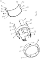
- Fig. 11 discloses an exploded view of yet another embodiment of a restriction unit 11 comprising an axially movable part 12 and a second part 14.
- the axially movable part 12 is a full ring, but shown in a cross-sectional view for illustrative purposes.
- the second part 14 has a base part 30 having a plurality of arms 31 projecting from the base part 30 in a direction of the axially movable part 12 and a plurality of second arms 41 projecting from the base part 30 away from the axially movable part 12.
- Each of the plurality of second arms 41 has an inner face 28 provided with grooves 42 for engaging an outer face of the body part 2.
- Each second arm 41 has an outer face having a part inclining away from the base part 30.
- the second part 14 further comprises a fastening ring 43 for sliding onto the outer face of the second arms 41, forcing the grooves 42 of the inner face 28 into engagement with the outer face of the body part 2 in order to fasten the second part 14 to the body part 2 without having to use screws.
- the fastening ring 43 has inwardly extending projections 46 inclining towards the second arms 41 so that when the fastening ring 43 is slid onto the outer face of the second arms 41, the inclined surface of the projections 46 functions as a wedge, forcing the grooves 42 even further into engagement with the outer face of the body part 2 the longer the fastening ring 46 is moved towards the base part 30.
- the axially movable part 12 has an indentation 38 in an outer face 44 of the axially movable part 12 in order to engage the inwardly extending projection 32 in the first position of the axially movable part 12.
- the inwardly extending projection 32 is forced to pass the annular projection 34 and slide further along the intermediate section 35 when the axially movable part 12 is forced away from the metal patch 10 as the expandable tubular packer element 3 expands.
- the axially movable part 12 also comprises the inclined face 22 assisting the expandable tubular packer element 3 in moving the axially movable part 12 away from the expandable tubular packer element 3 during expansion.
- the fastening ring 43 has a plurality of axially extending bores in order to fasten the fastening ring 43 to the base part 30 by means of e.g. screws.
- fluid or "well fluid” is meant any kind of fluid that may be present in oil or gas wells downhole, such as natural gas, oil, oil mud, crude oil, water, etc.
- gas is meant any kind of gas composition present in a well, completion, or open hole, and by “oil” is meant any kind of oil composition, such as crude oil, an oil-containing fluid, etc.
- Oil and water fluids may thus all comprise other elements or substances than gas, oil and/or water, respectively.
- casing or “well tubular metal structure” is meant any kind of pipe, tubing, tubular, liner, string, etc., used downhole in relation to oil or natural gas production.
- a downhole tractor can be used to push the tool all the way into position in the well.
- the downhole tractor may have projectable arms having wheels, wherein the wheels contact the inner surface of the casing for propelling the tractor and the tool forward in the casing.
- a downhole tractor is any kind of driving tool capable of pushing or pulling tools in a well downhole, such as a Well Tractor ® .
Landscapes
- Engineering & Computer Science (AREA)
- Geology (AREA)
- Life Sciences & Earth Sciences (AREA)
- Mining & Mineral Resources (AREA)
- Environmental & Geological Engineering (AREA)
- Fluid Mechanics (AREA)
- Physics & Mathematics (AREA)
- General Life Sciences & Earth Sciences (AREA)
- Geochemistry & Mineralogy (AREA)
- General Engineering & Computer Science (AREA)
- Mechanical Engineering (AREA)
- Earth Drilling (AREA)
- Consolidation Of Soil By Introduction Of Solidifying Substances Into Soil (AREA)
- Laying Of Electric Cables Or Lines Outside (AREA)
Abstract
The present invention relates to a downhole packer assembly for expansion of a metal sleeve, such as a metal patch, in a well downhole in a well tubular metal structure, the well having a top comprising a body part having an axial extension, a first end facing downhole and a second end facing uphole towards the top of the well, an expandable tubular packer element surrounding the body part, and a first end and a second end of the expandable tubular packer element are fixedly connected with the body part, providing an expandable space therebetween, the expandable space being fillable with liquid during expansion, and a metal sleeve surrounding the expandable tubular packer element, wherein the downhole packer assembly further comprises a restriction unit comprising an axially movable part, the axially movable part having a first part end facing the first end of the expandable tubular packer element and a second part end facing away from the expandable tubular packer element, the axially movable part having a first position in which the axially movable part at least partly overlaps the expandable tubular packer element and a second position in which the axially movable part has been axially displaced in relation to the body part away from the expandable tubular packer element. The invention also relates to a downhole system comprising the downhole packer assembly and a driving unit, such as a downhole tractor, for propelling the downhole packer assembly in the well tubular metal structure.
Description
- The present invention relates to a downhole packer assembly for expansion of a metal sleeve, such as a metal patch, in a well downhole in a well tubular metal structure. The invention also relates to a downhole system comprising the downhole packer assembly and a driving unit, such as a downhole tractor, for propelling the downhole packer assembly in the well tubular metal structure.
- When expanding a metal patch within a well tubular metal structure by means of a wireline tool, it is important to be able to run the unexpanded patch into the well without risking that the patch falls off the tool if power is temporarily lost. When using drill pipe or coiled tubing conveyed tools, there is no risk that the electrical power will be switched off since the pipe/tubing transports the pressurised fluid for expanding the patch, and thus no electrical power downhole is needed.
- It is an object of the present invention to wholly or partly overcome the above disadvantages and drawbacks of the prior art. More specifically, it is an object to provide an improved downhole packer assembly for expanding a metal patch within a well tubular metal structure without the risk of losing an unexpanded or only partly expanded metal patch downhole.
- The above objects, together with numerous other objects, advantages and features, which will become evident from the below description, are accomplished by a solution in accordance with the present invention by a downhole packer assembly for expansion of a metal sleeve, such as a metal patch, in a well downhole in a well tubular metal structure, the well having a top comprising:
- a body part having an axial extension, a first end facing downhole and a second end facing uphole towards the top of the well,
- an expandable tubular packer element surrounding the body part, and a first end and a second end of the expandable tubular packer element are fixedly connected with the body part, providing an expandable space therebetween, the expandable space being fillable with liquid during expansion, and
- a metal sleeve surrounding the expandable tubular packer element,
- Moreover, the axially movable part may have a length along the axial extension and may overlap the expandable tubular packer element by a distance being more than 10% of the length, preferably more than 25% of the length, even more preferably more than 50% of the length.
- Further, the axially movable part may move from the first position to the second position as the expandable tubular packer element expands and forces the axially movable part away from the expandable tubular packer element.
- In addition, the first part end of the axially movable part may have an inclined face inclining from an end point radially inwards towards the body part.
- Also, the first part end of the axially movable part may have an inclined face facing an outer face of the expandable tubular packer element in the first position.
- Furthermore, the first part end of the axially movable part may have an inclined face inclining from an end point radially inwards towards an inner face of the axially movable part.
- Moreover, the axially movable part may be ring-shaped.
- Further, the expandable tubular packer element may have an outer face having a friction coefficient, the axially movable part being maintained in the first position by friction between the outer face and inner face of the first part of the axially movable part.
- In addition, the body part may have a projection increasing the outer diameter of the body part that is larger than an inner diameter of the axially movable part.
- Also, the axially movable part may be maintained in the first position by a shear pin.
- Furthermore, the axially movable part may be maintained in the first position by a snap ring or a spring-loaded element movable in a first groove in the body part and engaging a first indentation in an inner face of the axially movable part.
- Moreover, the axially movable part may have a second indentation arranged in the inner face of the axially movable part at a distance from the first indentation and closer to the metal sleeve than the first indentation.
- Further, the restriction unit may comprise a second part fixedly connected to the body part.
- In addition, the second part may have a plurality of second arms having an inner face provided with grooves for engaging an outer face of the body part.
- Also, each second arm may have an outer face inclining away from the axially movable part.
- Furthermore, the second part may comprise a fastening ring for sliding onto the outer face of the second arms, forcing the grooves of the inner face into engagement with the outer face of the body part.
- Moreover, the second part may be a projection on the body part.
- Further, the second part may be a snap ring or a spring-loaded element movable radially and axially fixated in a first groove in the body part.
- In addition, the restriction unit may be a first restriction unit.
- Also, the downhole packer assembly may comprise a second restriction unit comprising an axially movable part, the axially movable part having a first part end facing the first end of the expandable tubular packer element and a second part end facing away from the expandable tubular packer element, the axially movable part having a first position in which the axially movable part at least partly overlaps the expandable tubular packer element and a second position in which the axially movable part has been axially displaced in relation to the body part away from the expandable tubular packer element towards the top of the well.
- Further, the axially movable part and/or the second part of the restriction unit may have a base part and extending arms each having an inwardly extending projection.
- In addition, the arms may have a thickness smaller than a thickness of the base part.
- Also, the arms may be more flexible than the base part.
- Furthermore, the base part may have openings for screwing the base part to the body part.
- Moreover, the axially movable part may be ring-shaped, the second part end having an annular projection, and the axially movable part comprising an intermediate section having an outer diameter smaller than that of the annular projection.
- Further, the first part end of the axially movable part may have an inclined face facing the metal sleeve.
- In addition, the inclined face may correspond to an inclined face at the end of the metal sleeve.
- Also, the axially movable part may have an indentation in an outer face of the axially movable part.
- Finally, the present invention relates to a downhole system comprising the downhole packer assembly and a driving unit, such as a downhole tractor, for propelling the downhole packer assembly in the well tubular metal structure.
- The invention and its many advantages will be described in more detail below with reference to the accompanying schematic drawings, which for the purpose of illustration show some non-limiting embodiments and in which:
-
Fig. 1 shows a partly cross-sectional view of a downhole packer assembly in a well, where the metal patch to be expanded is shown in its unexpanded condition, -
Fig. 2A shows a partly cross-sectional view of another downhole packer assembly in an unexpanded condition of the metal patch, -
Fig. 2B shows the downhole packer assembly ofFig. 2B in its expanded condition, -
Fig. 3 shows a partly cross-sectional view of another downhole packer assembly in an unexpanded condition of the metal patch, -
Fig. 4 shows a partly cross-sectional view of yet another downhole packer assembly in an unexpanded condition of the metal patch, -
Fig. 5 shows a cross-sectional view of part of a downhole packer assembly, -
Fig. 6 shows a cross-sectional view of part of another downhole packer assembly, -
Fig. 7 shows a perspective of part of yet another downhole packer assembly, -
Fig. 8 shows a perspective of a second part of a restriction unit, -
Fig. 9 shows part of a restriction unit, -
Fig. 10A shows a perspective of part of yet another downhole packer assembly, -
Fig. 10B shows part of the downhole packer assembly ofFig. 10B in its expanded condition, and -
Fig. 11 shows an exploded view of a restriction unit. - All the figures are highly schematic and not necessarily to scale, and they show only those parts which are necessary in order to elucidate the invention, other parts being omitted or merely suggested.
-
Fig. 1 shows adownhole packer assembly 1 for expansion of a metal sleeve, such as ametal patch 10, in a well 111 downhole in a welltubular metal structure 103, the well having atop 51. Thedownhole packer assembly 1 comprises abody part 2 having an axial extension L, afirst end 8 facing downhole and asecond end 9 facing uphole towards the top of the well. Thedownhole packer assembly 1 further comprises an expandabletubular packer element 3 surrounding thebody part 2, and afirst end 5 and asecond end 6 of the expandabletubular packer element 3 are fixedly connected with thebody part 2, providing anexpandable space 4 therebetween, and theexpandable space 4 being fillable with liquid during expansion in order to expand the expandabletubular packer element 3 and ametal sleeve 10 surrounding the expandabletubular packer element 3. Thedownhole packer assembly 1 further comprises a restriction unit (11, 11A) for restricting the expandabletubular packer element 3 from moving along the axial extension or falling off while running thedownhole packer assembly 1 into the vertical part of the well tubular metal structure. Thedownhole packer assembly 1 may also bump into restrictions in the well which may force the expandabletubular packer element 3 to move if not restricted from doing so by therestriction unit 11. Therestriction unit 11 comprises an axiallymovable part 12 having afirst part end 15 facing the first end of the expandabletubular packer element 3 and asecond part end 16 facing away from the expandabletubular packer element 3. The axiallymovable part 12 has a first position in which the axiallymovable part 12 at least partly overlaps and abuts the expandable tubular packer element 3 (as shown inFig. 2A ) and a second position in which the axiallymovable part 12 has been axially displaced in relation to thebody part 2 away from the expandable tubular packer element 3 (as shown inFig. 2B ). - By having an axially movable part moving from a first position and a second position by means of expanding the expandable
tubular packer element 3, a simple restriction of themetal patch 10 is accomplished so that an unexpanded or partly expandedmetal patch 10 is not lost in the well if the power is temporarily lost during conveying thedownhole packer assembly 1 in the well tubular metal structure. Therestriction unit 11 is able to maintain themetal patch 10 in the intended position without restricting the ends of themetal patch 10 from expanding. - The
downhole packer assembly 1 inFig. 1 also comprises apositive displacement pump 93 for pumping liquid into theexpandable space 4 to expand the expandabletubular packer element 3. Thepositive displacement pump 93 is connected to the top via a wireline 104 and acable head 109. Thepositive displacement pump 93 comprises anelectrical control 105. Thepositive displacement pump 93 comprises amotor 106 driving a second pump. Thepositive displacement pump 93 further comprises acompensator 107 for keeping a predetermined overpressure in thepositive displacement pump 93 compared to the surrounding pressure. Thepositive displacement pump 93 further comprises a driving means 112 to the movement of a first piston in the pump housing in a first direction or a second direction. InFig. 1 , thepositive displacement pump 93 further comprises adischarge control unit 90 having anaperture 91 for discharging fluid in the expandabletubular packer element 3 of thedownhole packer assembly 1 in order to deflate the expandabletubular packer element 3. Thedownhole packer assembly 1 is shown in its deflated position. Thedischarge control unit 90 may be a flow-operateddischarge control unit 90. - In
Fig. 1 , the axiallymovable part 12 has a length x along the axial extension L and overlaps the expandabletubular packer element 3 by a distance d (also shown inFig. 6 ) which is more than 10% of the length x, preferably more than 25% of the length x, and inFig. 1 more than 50% of the length x. When theexpandable space 4 of the expandabletubular packer element 3 is pressurised and thus expands, the axiallymovable part 12 is forced to move from the first position to the second position in that the radial expansion of the expandabletubular packer element 3 forces the axiallymovable part 12 to slide away from the expandabletubular packer element 3. - In another embodiment, the axially
movable part 12 may at least partly overlap an end of themetal sleeve 10, and once the axiallymovable part 12 slides at least partly off the expandabletubular packer element 3, the axiallymovable part 12 moves from the first position in which it overlaps themetal sleeve 10 to the second position where themetal sleeve 10 is free to move radially outwards along with the expandabletubular packer element 3. - The
first part end 15 of the axiallymovable part 12 has an inclined face 22 (also shown inFigs. 5 and 6 ) inclining from anend point 23 radially inwards towards thebody part 2. Once the expandabletubular packer element 3 starts to expand, theinclined face 22 assists the axiallymovable part 12 in moving towards thefirst end 8 of thebody part 2 and thus sliding off the expandabletubular packer element 3. - The axially
movable part 12 is ring-shaped, but may have any suitable shape and may be a two-part sleeve which is assembled and fastened around thebody part 2 and the expandabletubular packer element 3. - As shown in
Figs. 1 and6 , the axiallymovable part 12 is maintained in the first position by asnap ring 18 radially movable in afirst groove 20 in thebody part 2 and engaging afirst indentation 25 in an inner face of the axiallymovable part 12. The axiallymovable part 12 has asecond indentation 26 arranged in the inner face of the axiallymovable part 12 at a distance from thefirst indentation 25 and closer to themetal sleeve 10 than the first indentation. In this way, thesecond indentation 26 engages thesnap ring 18 when the axiallymovable part 12 moves from the first position to the second position, and the axiallymovable part 12 is thus locked in the second position so that the axiallymovable part 12 does not slide fully off thebody part 2. - In one embodiment, the expandable
tubular packer element 3 has anouter face 7 having a friction coefficient, and the axiallymovable part 12 is maintained in the first position by friction between the outer face and an inner face of the first part of the axiallymovable part 12. - In
Figs. 2A and 2B , thebody part 2 has aprojection 21 increasing the outer diameter of thebody part 2 so that the outer diameter of theprojection 21 is larger than an inner diameter of the axiallymovable part 12, and theprojection 21 thus prevents the axiallymovable part 12 from sliding off thebody part 2, as shown inFig. 2B . InFig. 3 , thebody part 2 has twoprojections 21 arranged at a distance from each of the axiallymovable parts 12 in the first position in order to prevent the axiallymovable parts 12 from sliding off thebody part 2. - In
Fig. 4 , thedownhole packer assembly 1 comprises afirst restriction unit first end 8 and asecond restriction unit second end 9. Eachrestriction unit 11 comprises the axiallymovable part 12, which is maintained in the first position by ashear pin 17. Once the expandabletubular packer element 3 starts to expand, a force starts to press on both the first and thesecond restriction unit movable parts 12 are forced to move away from the expandabletubular packer element 3. - The axially
movable part 12 may also be maintained in the first position by a spring-loadedelement 19, as shown inFig. 5 , which is movable in afirst groove 20 in thebody part 2 and engaging afirst indentation 25 in aninner face 28 of the axiallymovable part 12. The axiallymovable part 12 has asecond indentation 26 arranged in theinner face 28 of the axiallymovable part 12 at a distance from thefirst indentation 25 and closer to themetal sleeve 10 than thefirst indentation 25. In this way, thesecond indentation 26 engages the spring-loadedelement 19 when the axiallymovable part 12 moves from the first position to the second position, and the axiallymovable part 12 is thus locked in the second position so that the axiallymovable part 12 does not slide fully off thebody part 2. - As shown in
Figs. 3 ,7 and9 , therestriction unit 11 further comprises asecond part 14 fixedly connected to thebody part 2. InFig. 7 , the axiallymovable part 12 has abase part 30 and an extendingarm 31 having an inwardly extendingprojection 32 for engaging thesecond part 14 in the form of aprojection 21 when the axiallymovable part 12 moves to the second position away from themetal sleeve 10. InFig. 8 , thesecond part 14 has a plurality ofarms 31 with inwardly extendingprojections 32 for engaging a projection of the axiallymovable part 12. Thebase part 30 of thesecond part 14 hasopenings 33 for screwing thebase part 30 to thebody part 2. Thus, both the axiallymovable part 12 and the second part of the restriction unit may have abase part 30 and extendingarms 31, each having an inwardly extendingprojection 32, and the other axially movable part and the second part have an engageable projection. As shown inFig. 7 , the arm(s) has a thickness t1 smaller than a thickness t2 of thebase part 30. The arm(s) is thus made more flexible than thebase part 30 so as to be able to bend radially outwards when forced past the projection and to flex inwards again after having passed the projection. Thesecond part 14 may be the snap ring 18 (shown inFig. 6 ) or a spring-loaded element 19 (shown inFig. 5 ) movable radially and axially fixated in afirst groove 20 in thebody part 2. - In
Fig. 10A , therestriction unit 11 has an axiallymovable part 12 abutting the metal sleeve 10 (indicated with a dotted line for illustration purposes), and thesecond part 14 of therestriction unit 11 has abase part 30 and a plurality ofarms 31 with an inwardly extendingprojection 32 abutting thesecond part end 16 of the axiallymovable part 12. Thebase part 30 of thesecond part 14 is fastened to thebody part 2. The axiallymovable part 12 is shown in the first position inFig. 10A and in its second position inFig. 10B . The axiallymovable part 12 is ring-shaped, and thesecond part end 16 thereof has anannular projection 34. Further, the axiallymovable part 12 comprises anintermediate section 35 having an outer diameter OD1 smaller than that of theannular projection 34. InFig. 10B , the arms have passed theannular projection 34 as the ring-shaped axiallymovable part 12 has been forced underneath the arms as the expandabletubular packer element 3 expands as shown inFig. 10B . Thefirst part end 15 of the axiallymovable part 12 has aninclined face 36 facing themetal sleeve 10, and theinclined face 36 corresponds to aninclined face 37 at the end of themetal sleeve 10. When having asecond restriction unit 11 at the other end of themetal sleeve 10, themetal sleeve 10 is fastened between the first andsecond restriction units 11 until the expandabletubular packer element 3 expands, forcing the axiallymovable parts 12 away from the expandabletubular packer element 3 and underneath the arms of thesecond parts 14, as shown inFig. 10B . The smaller outer diameter of theintermediate section 35 enables the arms to bend inwards again after having passed theannular projections 34 engaging the axiallymovable parts 12. -
Fig. 9 discloses a part view of arestriction unit 11 having an axiallymovable part 12 and thesecond part 14. Thesecond part 14 has a plurality ofarms 31 engaging a plurality ofarms 31 of the axiallymovable part 12. The arms of the axiallymovable part 12 haveprojections 32 engaging grooves adjacent to the projections of the arms of thesecond part 14, and the arms of thesecond part 14 haveprojections 32 engaging grooves adjacent to the projections of the arms of the axiallymovable part 12. Each of the axiallymovable part 12 and thesecond part 14 has a plurality ofarms 31 distributed along the circumference of thebody part 2. -
Fig. 11 discloses an exploded view of yet another embodiment of arestriction unit 11 comprising an axiallymovable part 12 and asecond part 14. The axiallymovable part 12 is a full ring, but shown in a cross-sectional view for illustrative purposes. Thesecond part 14 has abase part 30 having a plurality ofarms 31 projecting from thebase part 30 in a direction of the axiallymovable part 12 and a plurality ofsecond arms 41 projecting from thebase part 30 away from the axiallymovable part 12. Each of the plurality ofsecond arms 41 has aninner face 28 provided withgrooves 42 for engaging an outer face of thebody part 2. Eachsecond arm 41 has an outer face having a part inclining away from thebase part 30. Thesecond part 14 further comprises afastening ring 43 for sliding onto the outer face of thesecond arms 41, forcing thegrooves 42 of theinner face 28 into engagement with the outer face of thebody part 2 in order to fasten thesecond part 14 to thebody part 2 without having to use screws. Thefastening ring 43 has inwardly extendingprojections 46 inclining towards thesecond arms 41 so that when thefastening ring 43 is slid onto the outer face of thesecond arms 41, the inclined surface of theprojections 46 functions as a wedge, forcing thegrooves 42 even further into engagement with the outer face of thebody part 2 the longer thefastening ring 46 is moved towards thebase part 30. Furthermore, the axiallymovable part 12 has anindentation 38 in anouter face 44 of the axiallymovable part 12 in order to engage the inwardly extendingprojection 32 in the first position of the axiallymovable part 12. In the second position of the axiallymovable part 12, the inwardly extendingprojection 32 is forced to pass theannular projection 34 and slide further along theintermediate section 35 when the axiallymovable part 12 is forced away from themetal patch 10 as the expandabletubular packer element 3 expands. The axiallymovable part 12 also comprises theinclined face 22 assisting the expandabletubular packer element 3 in moving the axiallymovable part 12 away from the expandabletubular packer element 3 during expansion. Thefastening ring 43 has a plurality of axially extending bores in order to fasten thefastening ring 43 to thebase part 30 by means of e.g. screws. - By "fluid" or "well fluid" is meant any kind of fluid that may be present in oil or gas wells downhole, such as natural gas, oil, oil mud, crude oil, water, etc. By "gas" is meant any kind of gas composition present in a well, completion, or open hole, and by "oil" is meant any kind of oil composition, such as crude oil, an oil-containing fluid, etc. Gas, oil and water fluids may thus all comprise other elements or substances than gas, oil and/or water, respectively.
- By "casing" or "well tubular metal structure" is meant any kind of pipe, tubing, tubular, liner, string, etc., used downhole in relation to oil or natural gas production.
- In the event that the tool is not submergible all the way into the casing, a downhole tractor can be used to push the tool all the way into position in the well. The downhole tractor may have projectable arms having wheels, wherein the wheels contact the inner surface of the casing for propelling the tractor and the tool forward in the casing. A downhole tractor is any kind of driving tool capable of pushing or pulling tools in a well downhole, such as a Well Tractor®.
- Although the invention has been described above in connection with preferred embodiments of the invention, it will be evident to a person skilled in the art that several modifications are conceivable without departing from the invention as defined by the following claims.
Claims (15)
- A downhole packer assembly (1) for expansion of a metal sleeve, such as a metal patch (10), in a well (11) downhole in a well tubular metal structure (103), the well having a top (51) comprising:- a body part (2) having an axial extension (L), a first end (8) facing downhole and a second end (9) facing uphole towards the top of the well,- an expandable tubular packer element (3) surrounding the body part, and a first end (5) and a second end (6) of the expandable tubular packer element are fixedly connected with the body part, providing an expandable space (4) therebetween, the expandable space being fillable with liquid during expansion, and- a metal sleeve (10) surrounding the expandable tubular packer element,wherein the downhole packer assembly further comprises a restriction unit (11, 11A) comprising an axially movable part (12), the axially movable part having a first part end (15) facing the first end of the expandable tubular packer element and a second part end (16) facing away from the expandable tubular packer element, the axially movable part having a first position in which the axially movable part at least partly overlaps the expandable tubular packer element and a second position in which the axially movable part has been axially displaced in relation to the body part away from the expandable tubular packer element.
- A downhole packer assembly according to claim 1, wherein the axially movable part has a length (x) along the axial extension and overlaps the expandable tubular packer element by a distance (d) being more than 10% of the length, preferably more than 25% of the length, even more preferably more than 50% of the length.
- A downhole packer assembly according to claim 1 or 2, wherein the axially movable part moves from the first position to the second position as the expandable tubular packer element expands and forces the axially movable part away from the expandable tubular packer element.
- A downhole packer assembly according to any of the preceding claims, wherein the first part end of the axially movable part has an inclined face (22) inclining from an end point (23) radially inwards towards the body part.
- A downhole packer assembly according to any of the preceding claims, wherein the axially movable part is maintained in the first position by a snap ring (18) or a spring-loaded element (19) movable in a first groove (20) in the body part and engaging a first indentation in an inner face of the axially movable part.
- A downhole packer assembly according to any of the preceding claims, wherein the restriction unit further comprises a second part (14) fixedly connected to the body part.
- A downhole packer assembly according to claim 6, wherein the second part is a projection (21) on the body part.
- A downhole packer assembly according to claim 6, wherein the second part is a snap ring (18) or a spring-loaded element (19) movable radially and axially fixated in a first groove (20) in the body part.
- A downhole packer assembly according to any of the preceding claims, further comprising a second restriction unit (11, 11B) comprising an axially movable part (12), the axially movable part having a first part end (15) facing the first end of the expandable tubular packer element and a second part end (16) facing away from the expandable tubular packer element, the axially movable part having a first position in which the axially movable part at least partly overlaps the expandable tubular packer element and a second position in which the axially movable part has been axially displaced in relation to the body part away from the expandable tubular packer element.
- A downhole packer assembly according to any of the preceding claims, wherein the axially movable part and/or the second part of the restriction unit has/have a base part (30) and extending arms (31), each having an inwardly extending projection (32).
- A downhole packer assembly according to any of the preceding claims, wherein the axially movable part is ring-shaped, the second part end (16) having an annular projection (34), and the axially movable part comprising an intermediate section (35) having an outer diameter (OD1) smaller than that of the annular projection.
- A downhole packer assembly according to claim 11, wherein the first part end of the axially movable part has an inclined face (36) facing the metal sleeve.
- A downhole packer assembly according to claim 12, wherein the inclined face corresponds to an inclined face (37) at the end of the metal sleeve.
- A downhole packer assembly according to any of the preceding claims, wherein the axially movable part has an indentation (38) in an outer face of the axially movable part.
- A downhole system (100) comprising the downhole packer assembly according to any of claims 1-14 and a driving unit, such as a downhole tractor, for propelling the downhole packer assembly in the well tubular metal structure.
Priority Applications (7)
| Application Number | Priority Date | Filing Date | Title |
|---|---|---|---|
| EP20209615.2A EP4001584A1 (en) | 2020-11-24 | 2020-11-24 | Downhole packer assembly |
| AU2021388758A AU2021388758B2 (en) | 2020-11-24 | 2021-11-23 | Downhole packer assembly |
| CN202180075948.1A CN116529454A (en) | 2020-11-24 | 2021-11-23 | Downhole packer assembly |
| EP21816433.3A EP4251847A1 (en) | 2020-11-24 | 2021-11-23 | Downhole packer assembly |
| US17/534,078 US11624256B2 (en) | 2020-11-24 | 2021-11-23 | Downhole packer assembly |
| PCT/EP2021/082654 WO2022112235A1 (en) | 2020-11-24 | 2021-11-23 | Downhole packer assembly |
| SA523440650A SA523440650B1 (en) | 2020-11-24 | 2023-05-08 | Collecting a filling in a well hole |
Applications Claiming Priority (1)
| Application Number | Priority Date | Filing Date | Title |
|---|---|---|---|
| EP20209615.2A EP4001584A1 (en) | 2020-11-24 | 2020-11-24 | Downhole packer assembly |
Publications (1)
| Publication Number | Publication Date |
|---|---|
| EP4001584A1 true EP4001584A1 (en) | 2022-05-25 |
Family
ID=73597830
Family Applications (2)
| Application Number | Title | Priority Date | Filing Date |
|---|---|---|---|
| EP20209615.2A Withdrawn EP4001584A1 (en) | 2020-11-24 | 2020-11-24 | Downhole packer assembly |
| EP21816433.3A Pending EP4251847A1 (en) | 2020-11-24 | 2021-11-23 | Downhole packer assembly |
Family Applications After (1)
| Application Number | Title | Priority Date | Filing Date |
|---|---|---|---|
| EP21816433.3A Pending EP4251847A1 (en) | 2020-11-24 | 2021-11-23 | Downhole packer assembly |
Country Status (6)
| Country | Link |
|---|---|
| US (1) | US11624256B2 (en) |
| EP (2) | EP4001584A1 (en) |
| CN (1) | CN116529454A (en) |
| AU (1) | AU2021388758B2 (en) |
| SA (1) | SA523440650B1 (en) |
| WO (1) | WO2022112235A1 (en) |
Families Citing this family (1)
| Publication number | Priority date | Publication date | Assignee | Title |
|---|---|---|---|---|
| CN118793398B (en) * | 2024-07-19 | 2024-12-27 | 太仓优尼泰克精密机械有限公司 | Packer capable of preventing sealing rubber and slips from failing |
Citations (2)
| Publication number | Priority date | Publication date | Assignee | Title |
|---|---|---|---|---|
| AU2013100386B4 (en) * | 2013-03-28 | 2013-09-12 | Welltec Oilfield Solutions Ag | Annular barrier |
| EP3517728A1 (en) * | 2018-01-25 | 2019-07-31 | Welltec Oilfield Solutions AG | Downhole wireline intervention tool |
Family Cites Families (1)
| Publication number | Priority date | Publication date | Assignee | Title |
|---|---|---|---|---|
| US7673692B2 (en) * | 2006-02-17 | 2010-03-09 | Bj Tool Services Ltd. | Eutectic material-based seal element for packers |
-
2020
- 2020-11-24 EP EP20209615.2A patent/EP4001584A1/en not_active Withdrawn
-
2021
- 2021-11-23 CN CN202180075948.1A patent/CN116529454A/en active Pending
- 2021-11-23 WO PCT/EP2021/082654 patent/WO2022112235A1/en not_active Ceased
- 2021-11-23 AU AU2021388758A patent/AU2021388758B2/en active Active
- 2021-11-23 US US17/534,078 patent/US11624256B2/en active Active
- 2021-11-23 EP EP21816433.3A patent/EP4251847A1/en active Pending
-
2023
- 2023-05-08 SA SA523440650A patent/SA523440650B1/en unknown
Patent Citations (2)
| Publication number | Priority date | Publication date | Assignee | Title |
|---|---|---|---|---|
| AU2013100386B4 (en) * | 2013-03-28 | 2013-09-12 | Welltec Oilfield Solutions Ag | Annular barrier |
| EP3517728A1 (en) * | 2018-01-25 | 2019-07-31 | Welltec Oilfield Solutions AG | Downhole wireline intervention tool |
Also Published As
| Publication number | Publication date |
|---|---|
| AU2021388758A1 (en) | 2023-07-06 |
| WO2022112235A1 (en) | 2022-06-02 |
| US11624256B2 (en) | 2023-04-11 |
| EP4251847A1 (en) | 2023-10-04 |
| SA523440650B1 (en) | 2024-11-11 |
| CN116529454A (en) | 2023-08-01 |
| US20220162924A1 (en) | 2022-05-26 |
| AU2021388758B2 (en) | 2025-01-30 |
Similar Documents
| Publication | Publication Date | Title |
|---|---|---|
| US8291989B2 (en) | Retrieval method for opposed slip type packers | |
| US11098554B2 (en) | Expanding and collapsing apparatus and methods of use | |
| US4359090A (en) | Anchoring mechanism for well packer | |
| EP2402553A1 (en) | Downhole apparatus and support structure therefor | |
| WO1985000850A1 (en) | Hydraulically set well packer | |
| AU2019476321B2 (en) | Zero extrusion gap barrier device used on packing elements | |
| US10774602B2 (en) | High radial expansion anchoring tool | |
| US11624256B2 (en) | Downhole packer assembly | |
| EP3265644B1 (en) | Downhole stroking tool | |
| US12065901B1 (en) | Expanding and collapsing apparatus having bookend seal cartridges | |
| CN111386381A (en) | Downhole patching systems | |
| EP3987150B1 (en) | Annular barrier with bite connection | |
| EP3891355B1 (en) | Downhole tool with a long projecting extension | |
| EA047346B1 (en) | IN-WELL PACKER UNIT | |
| EP4112874A1 (en) | Annular barrier | |
| US20260071512A1 (en) | Downhole packer assembly | |
| EP4707527A1 (en) | A downhole packer assembly | |
| EP4323620B1 (en) | Annular barrier and downhole system | |
| CA3250150A1 (en) | METHOD AND APPARATUS FOR INSTALLING BOTTOM PLUGS AND OTHER OBJECTS IN WELLS | |
| CN117500998A (en) | ring barrier | |
| AU2021459597A1 (en) | Slip ring employing radially offset slot | |
| EP3112581A1 (en) | Downhole stroking tool | |
| WO2023014349A1 (en) | Slip ring employing radially offset slot |
Legal Events
| Date | Code | Title | Description |
|---|---|---|---|
| PUAI | Public reference made under article 153(3) epc to a published international application that has entered the european phase |
Free format text: ORIGINAL CODE: 0009012 |
|
| STAA | Information on the status of an ep patent application or granted ep patent |
Free format text: STATUS: THE APPLICATION HAS BEEN PUBLISHED |
|
| AK | Designated contracting states |
Kind code of ref document: A1 Designated state(s): AL AT BE BG CH CY CZ DE DK EE ES FI FR GB GR HR HU IE IS IT LI LT LU LV MC MK MT NL NO PL PT RO RS SE SI SK SM TR |
|
| STAA | Information on the status of an ep patent application or granted ep patent |
Free format text: STATUS: THE APPLICATION IS DEEMED TO BE WITHDRAWN |
|
| 18D | Application deemed to be withdrawn |
Effective date: 20221126 |