EP4000976A1 - Transport refrigeration unit with variable-speed electric refrigeration drive and variable-speed diesel engine synchronous generator power source - Google Patents
Transport refrigeration unit with variable-speed electric refrigeration drive and variable-speed diesel engine synchronous generator power source Download PDFInfo
- Publication number
- EP4000976A1 EP4000976A1 EP21204031.5A EP21204031A EP4000976A1 EP 4000976 A1 EP4000976 A1 EP 4000976A1 EP 21204031 A EP21204031 A EP 21204031A EP 4000976 A1 EP4000976 A1 EP 4000976A1
- Authority
- EP
- European Patent Office
- Prior art keywords
- engine
- compressor
- operating
- tru
- speed
- Prior art date
- Legal status (The legal status is an assumption and is not a legal conclusion. Google has not performed a legal analysis and makes no representation as to the accuracy of the status listed.)
- Withdrawn
Links
Images

Classifications
-
- B—PERFORMING OPERATIONS; TRANSPORTING
- B60—VEHICLES IN GENERAL
- B60H—ARRANGEMENTS OF HEATING, COOLING, VENTILATING OR OTHER AIR-TREATING DEVICES SPECIALLY ADAPTED FOR PASSENGER OR GOODS SPACES OF VEHICLES
- B60H1/00—Heating, cooling or ventilating devices
- B60H1/32—Cooling devices
- B60H1/3204—Cooling devices using compression
- B60H1/3232—Cooling devices using compression particularly adapted for load transporting vehicles
-
- B—PERFORMING OPERATIONS; TRANSPORTING
- B60—VEHICLES IN GENERAL
- B60H—ARRANGEMENTS OF HEATING, COOLING, VENTILATING OR OTHER AIR-TREATING DEVICES SPECIALLY ADAPTED FOR PASSENGER OR GOODS SPACES OF VEHICLES
- B60H1/00—Heating, cooling or ventilating devices
- B60H1/00421—Driving arrangements for parts of a vehicle air-conditioning
- B60H1/00428—Driving arrangements for parts of a vehicle air-conditioning electric
-
- H—ELECTRICITY
- H02—GENERATION; CONVERSION OR DISTRIBUTION OF ELECTRIC POWER
- H02P—CONTROL OR REGULATION OF ELECTRIC MOTORS, ELECTRIC GENERATORS OR DYNAMO-ELECTRIC CONVERTERS; CONTROLLING TRANSFORMERS, REACTORS OR CHOKE COILS
- H02P9/00—Arrangements for controlling electric generators for the purpose of obtaining a desired output
- H02P9/04—Control effected upon non-electric prime mover and dependent upon electric output value of the generator
-
- B—PERFORMING OPERATIONS; TRANSPORTING
- B60—VEHICLES IN GENERAL
- B60H—ARRANGEMENTS OF HEATING, COOLING, VENTILATING OR OTHER AIR-TREATING DEVICES SPECIALLY ADAPTED FOR PASSENGER OR GOODS SPACES OF VEHICLES
- B60H1/00—Heating, cooling or ventilating devices
- B60H1/00421—Driving arrangements for parts of a vehicle air-conditioning
- B60H1/0045—Driving arrangements for parts of a vehicle air-conditioning mechanical power take-offs from the vehicle propulsion unit
-
- B—PERFORMING OPERATIONS; TRANSPORTING
- B60—VEHICLES IN GENERAL
- B60H—ARRANGEMENTS OF HEATING, COOLING, VENTILATING OR OTHER AIR-TREATING DEVICES SPECIALLY ADAPTED FOR PASSENGER OR GOODS SPACES OF VEHICLES
- B60H1/00—Heating, cooling or ventilating devices
- B60H1/32—Cooling devices
- B60H1/3204—Cooling devices using compression
- B60H1/3205—Control means therefor
- B60H1/3208—Vehicle drive related control of the compressor drive means, e.g. for fuel saving purposes
-
- B—PERFORMING OPERATIONS; TRANSPORTING
- B60—VEHICLES IN GENERAL
- B60H—ARRANGEMENTS OF HEATING, COOLING, VENTILATING OR OTHER AIR-TREATING DEVICES SPECIALLY ADAPTED FOR PASSENGER OR GOODS SPACES OF VEHICLES
- B60H1/00—Heating, cooling or ventilating devices
- B60H1/32—Cooling devices
- B60H1/3204—Cooling devices using compression
- B60H1/3222—Cooling devices using compression characterised by the compressor driving arrangements, e.g. clutches, transmissions or multiple drives
-
- F—MECHANICAL ENGINEERING; LIGHTING; HEATING; WEAPONS; BLASTING
- F02—COMBUSTION ENGINES; HOT-GAS OR COMBUSTION-PRODUCT ENGINE PLANTS
- F02D—CONTROLLING COMBUSTION ENGINES
- F02D29/00—Controlling engines, such controlling being peculiar to the devices driven thereby, the devices being other than parts or accessories essential to engine operation, e.g. controlling of engines by signals external thereto
- F02D29/06—Controlling engines, such controlling being peculiar to the devices driven thereby, the devices being other than parts or accessories essential to engine operation, e.g. controlling of engines by signals external thereto peculiar to engines driving electric generators
-
- B—PERFORMING OPERATIONS; TRANSPORTING
- B60—VEHICLES IN GENERAL
- B60H—ARRANGEMENTS OF HEATING, COOLING, VENTILATING OR OTHER AIR-TREATING DEVICES SPECIALLY ADAPTED FOR PASSENGER OR GOODS SPACES OF VEHICLES
- B60H1/00—Heating, cooling or ventilating devices
- B60H1/32—Cooling devices
- B60H2001/3269—Cooling devices output of a control signal
- B60H2001/327—Cooling devices output of a control signal related to a compressing unit
- B60H2001/3272—Cooling devices output of a control signal related to a compressing unit to control the revolving speed of a compressor
-
- B—PERFORMING OPERATIONS; TRANSPORTING
- B60—VEHICLES IN GENERAL
- B60P—VEHICLES ADAPTED FOR LOAD TRANSPORTATION OR TO TRANSPORT, TO CARRY, OR TO COMPRISE SPECIAL LOADS OR OBJECTS
- B60P3/00—Vehicles adapted to transport, to carry or to comprise special loads or objects
- B60P3/20—Refrigerated goods vehicles
-
- F—MECHANICAL ENGINEERING; LIGHTING; HEATING; WEAPONS; BLASTING
- F02—COMBUSTION ENGINES; HOT-GAS OR COMBUSTION-PRODUCT ENGINE PLANTS
- F02D—CONTROLLING COMBUSTION ENGINES
- F02D29/00—Controlling engines, such controlling being peculiar to the devices driven thereby, the devices being other than parts or accessories essential to engine operation, e.g. controlling of engines by signals external thereto
- F02D29/02—Controlling engines, such controlling being peculiar to the devices driven thereby, the devices being other than parts or accessories essential to engine operation, e.g. controlling of engines by signals external thereto peculiar to engines driving vehicles; peculiar to engines driving variable pitch propellers
-
- F—MECHANICAL ENGINEERING; LIGHTING; HEATING; WEAPONS; BLASTING
- F02—COMBUSTION ENGINES; HOT-GAS OR COMBUSTION-PRODUCT ENGINE PLANTS
- F02D—CONTROLLING COMBUSTION ENGINES
- F02D41/00—Electrical control of supply of combustible mixture or its constituents
- F02D41/02—Circuit arrangements for generating control signals
- F02D41/0205—Circuit arrangements for generating control signals using an auxiliary engine speed control
-
- H—ELECTRICITY
- H02—GENERATION; CONVERSION OR DISTRIBUTION OF ELECTRIC POWER
- H02P—CONTROL OR REGULATION OF ELECTRIC MOTORS, ELECTRIC GENERATORS OR DYNAMO-ELECTRIC CONVERTERS; CONTROLLING TRANSFORMERS, REACTORS OR CHOKE COILS
- H02P2101/00—Special adaptation of control arrangements for generators
- H02P2101/25—Special adaptation of control arrangements for generators for combustion engines
Definitions
- the invention relates to transport refrigeration units (TRUs) and, in particular, to a TRU with a variable-speed electric refrigeration drive and a variable-speed diesel engine synchronous generator power source.
- TRUs for trucks and trailer are evolving toward being configured for full electrical operations. To this end, higher efficiency systems will ultimately need to be developed to enable such full electrical operations. In the meantime, interim solutions that do not involve, for example, battery only electrification, need to be developed that exceed the capabilities of current systems designed to run synchronously. Synchronous systems are characterized in that high engine speed results in high capacity, high airflow and high fuel consumption.
- a transport refrigeration (TRU) system includes an air management system, a compressor, a generator which generates alternating current (AC) from operations of an engine to power operations of the air management system and the compressor and an AC inverter operably interposed between the generator and the compressor to decouple a drive frequency of the compressor from a frequency of the generator.
- AC alternating current
- the compressor includes a variable speed compressor.
- the air management system includes parallel air management systems.
- the engine is run at a lowest possible engine speed for needed power and compressor speed is varied based on capacity demand.
- the engine continues to run at the lowest possible engine speed as the capacity demand increases to match a torque demanded from the compressor.
- engine speed increases as the engine approaches a maximum available power.
- a method of operating a transport refrigeration unit (TRU) system including an air management system, a compressor, a generator which generates alternating current (AC) from operations of an engine to power operations of the air management system and the compressor and an AC inverter operably interposed between the generator and the compressor is provided.
- the method includes decoupling a drive frequency of the compressor from a frequency of the generator.
- the decoupling of the drive frequency of the compressor from the frequency of the generator includes operating the compressor at a variable speed to meet a demand, operating an engine at a lowest possible speed to provide power for the compressor, maintaining operations of the engine at the lowest possible speed as the demand increases and increasing an engine speed of the engine as available power of the engine approaches a maximum.
- a method of operating a transport refrigeration unit (TRU) system in which a drive frequency of a compressor is decoupled from a frequency of a generator includes operating the compressor at a variable speed to meet a demand, operating an engine at a lowest possible speed to provide power for the compressor, maintaining operations of the engine at the lowest possible speed as the demand increases and increasing an engine speed of the engine as available power of the engine approaches a maximum.
- TRU transport refrigeration unit
- the operating of the engine includes determining whether the engine is operating within a desired load range.
- the operating of the engine further includes maintaining an engine speed if the engine is operating within the desired load range.
- the operating of the engine further includes increasing an engine speed if the engine is not operating within the desired load range and more engine power is required.
- the operating of the engine further includes reducing engine power and decreasing engine speed if the engine is not operating within the desired load range and more engine power is not required.
- the operating of the compressor includes determining whether a TRU temperature error is greater than zero.
- the operating of the compressor further includes decreasing a compressor drive frequency if the TRU temperature error is not greater than zero and not equal to zero.
- the operating of the compressor further includes decreasing a compressor drive frequency if the TRU temperature error is greater than zero and an engine load is greater than a maximum load range.
- the operating of the compressor further includes maintaining the compressor drive frequency if the TRU temperature error is not greater than zero and is equal to zero.
- the operating of the compressor further includes maintaining the compressor drive frequency if the TRU temperature error is greater than zero and if the engine load is not greater than a maximum load range, more engine power has been requested and engine power has not been increased.
- the operating of the compressor further includes maintaining the compressor drive frequency if the TRU temperature error is greater than zero and if the engine load is not greater than a maximum load range, more engine power has been requested, engine power has been increased and the compressor is at a maximum drive frequency.
- the operating of the compressor further includes increasing a compressor drive frequency if the TRU temperature error is greater than zero and if the engine load is not greater than a maximum load range, more engine power has been requested, engine power has been increased and the compressor is not at a maximum drive frequency.
- a refrigeration compressor drive frequency is decoupled from a primary diesel generator frequency using a refrigeration compressor variable speed AC inverter that is located between a 3-phase diesel synchronous generator and the compressor.
- the approach will be to allow the engine to run at lowest possible engine speeds for needed power while allowing the refrigeration system to vary operations of the primary compressor and if needed fan speeds based on capacity demands.
- the engine can stay in a lowest speed required to match torque demanded from the compressor and fan systems with intent of staying in lowest speed required to match demand of the refrigeration or compressor system. If engine power is approaching a maximum available power, the engine will increase in rpm to thereby increase available engine power to thus supply the AC inverter with power needed for the refrigeration compressor.
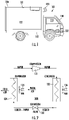
- a truck or trailer 101 includes a vehicle portion 110, a trailer portion 120 and a TRU 130.
- the vehicle portion 110 includes a cabin 111, which is supportive of an engine 112 and which is configured to accommodate an operator and one or more passengers, and a bed 113 in the rear of the cabin 111.
- the engine 112 can be provided as a diesel engine or another similar type of internal combustion engine.
- the trailer portion 120 can be seated on the bed 113 and has a body 121 that is formed to define an interior 122 in which items being transported or shipped can be stored.
- the TRU 130 is operably coupled directly or indirectly to and is configured to be seated upon the body 121 of the trailer portion 120.
- the TRU can include an engine and is configured to generate a cooling (or heating) airflow that can be directed into the interior 122 so as to control at least a temperature of the interior 122.
- a cooling (or heating) airflow that can be directed into the interior 122 so as to control at least a temperature of the interior 122.
- the TRU 130 can be operated according to a vapor compression cycle 200 and includes a compressor 131, a condenser 132, an expansion valve 133, an evaporator 134 and fans 135 and 136.
- the compressor 131 compresses vapor and outputs the compressed vapor to the condenser 132.
- the condenser 132 Within the condenser 132, the compressed vapor is condensed into a liquid, while the fan 136 blows air over and through the condenser 132, which is directed to the expansion valve 133.
- the liquid is expanded through the expansion valve 133 into a mixture of liquid and vapor that is directed to the evaporator 134.
- the mixture of liquid and vapor then flows through coils of the evaporator 134 while the fan 135 blows air (i.e., warm air) over the coils whereupon the liquid removes heat from the air and turns into vapor. This cools the air so that the air can be directed into the interior 122 as cooled air.
- the vapor is then flown into the compressor 131.
- a TRU system 301 is provided for handling certain operations of the TRU 130 of FIGS. 1 and 2 .
- the TRU system 301 can include an onboard engine 302 or, in some cases, can be directly or indirectly connected to another engine, such as the engine 112 of FIG. 1 .
- the following description will relate to the cases in which the engine 302 is an onboard engine of the TRU system 301.
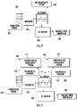
- the TRU system 301 further includes a generator 310, an alternating current (AC) inverter 320 and a variable speed compressor 330.
- the TRU system 301 further includes an air management system 340 (see FIG. 3 ) and/or parallel air management systems 401 and 402 (see FIG. 4 ).
- the generator 310 can include or be provided as a 3-phase diesel synchronous generator.
- the generator 310 can be directly or indirectly driven by the engine 302 to generate electricity and power for use by the variable speed compressor 330 and the air management system 340 of FIG. 3 and/or the parallel air management systems 401 and 402 of FIG. 4 .
- the AC inverter 320 can include or be provided as a refrigeration compressor variable speed AC inverter.
- the air management system (e.g., the parallel air management system 401 and 402) can include or be provided as one or more fan motor AC inverter(s) 412, 421 (i.e., for driving the fans 135 and 136 of FIG. 2 ).
- the air management system (i.e., when configured as a parallel air management system 401 and 402) may include an evaporator air management system 411 in series with the fan motor AC inverter 410, and a condenser air management system 421 in series with the fan motor AC inverter 420.
- the TRU system 301 of FIGS. 3 and 4 are thus characterized in that the refrigeration compressor drive frequency of at least the variable speed compressor 330 is decoupled from the primary diesel generator frequency of the generator 310 using the AC inverter 320 which is located or operably disposed between the generator 310 and the variable speed compressor 330.
- the TRU system 301 allows the engine 302 to run at a lowest possible engine speed for needed power while varying compressor and fan speeds based on capacity demand. As refrigeration power demand increases, the engine 302 can stay in a lowest speed that is required to match torque demanded from the compressor 131 and the fans 135 and 136 with the intent of staying in a lowest speed required to match the demand. If engine power is approaching a maximum available power, the engine 302 will increase in rpm to thus increase available engine power and to supply the AC inverter 320 with sufficient power as needed for the compressor 131 and the fans 135 and 136.
- the method or scheme includes a TRU control 501 that considers whether the engine 302 is within a desired load range for TRU control 502 as well as additional issues arising therefrom and whether a TRU temperature error is greater than zero 503 (i.e., whether a temperature within the interior 122 is at a target temperature or not) as well as additional issues arising therefrom.
- engine rpm is maintained 504. Conversely, if the engine 302 is not within the desired load range for the TRU control, it is determined whether more engine power is required from the TRU control 505 (see a determination of whether more engine power is requested at block 513 to be discussed below). If more engine power is not required, engine power is reduced 506 and engine rpm is decreased 507 and control reverts to considering whether the engine 302 is within a desired load range for TRU control 502. If more engine power is required, engine rpm is increased 508 and control reverts to considering whether the engine 302 is within a desired load range for TRU control 502.
- TRU temperature error is not greater than zero, it is determined whether TRU temperature error equals zero 509. If the TRU temperature error does not equal zero, a compressor drive frequency of the compressor 131 is decreased 510 and control reverts to determining whether the TRU temperature error is greater than zero 503. If the TRU temperature error equals zero, the compressor drive frequency is maintained 511 and control reverts to determining whether the TRU temperature error is greater than zero 503.
- the compressor drive frequency is decreased 510 and control reverts to determining whether the TRU temperature error is greater than zero 503. If the engine load is not greater than the maximum load range, more engine power is requested 513 and it is determined whether engine power has been increased to a desirable load range 514. If the engine power has not been increased to the desirable load range, the compressor drive frequency is maintained 511 and control reverts to determining whether the TRU temperature error is greater than zero 503. If the engine power has been increased to the desirable load range, it is determined whether the compressor 131 is at a maximum drive frequency 515.
- the compressor drive frequency is maintained 511 and control reverts to determining whether the TRU temperature error is greater than zero 503. If the compressor 131 is not at the maximum drive frequency, the compressor drive frequency is increased 516 and control reverts to determining whether the TRU temperature error is greater than zero 503.
- FIG. 6 a performance of the TRU system 301 of FIGS. 3 and 4 and operated according to the method or scheme of FIG. 5 is illustrated graphically. As shown in FIG. 6 it is apparent that an operational capability of the compressor 131 is greatly increased from low engine rpm to high engine rpm and from low compressor capacity to high compressor capacity resulting from the use of a variable speed compressor as compared to synchronous units.
Landscapes
- Engineering & Computer Science (AREA)
- Mechanical Engineering (AREA)
- Physics & Mathematics (AREA)
- Thermal Sciences (AREA)
- Power Engineering (AREA)
- Chemical & Material Sciences (AREA)
- Combustion & Propulsion (AREA)
- General Engineering & Computer Science (AREA)
- Devices That Are Associated With Refrigeration Equipment (AREA)
Abstract
Description
- The invention relates to transport refrigeration units (TRUs) and, in particular, to a TRU with a variable-speed electric refrigeration drive and a variable-speed diesel engine synchronous generator power source.
- TRUs for trucks and trailer are evolving toward being configured for full electrical operations. To this end, higher efficiency systems will ultimately need to be developed to enable such full electrical operations. In the meantime, interim solutions that do not involve, for example, battery only electrification, need to be developed that exceed the capabilities of current systems designed to run synchronously. Synchronous systems are characterized in that high engine speed results in high capacity, high airflow and high fuel consumption.
- According to a first aspect of the invention, a transport refrigeration (TRU) system is provided and includes an air management system, a compressor, a generator which generates alternating current (AC) from operations of an engine to power operations of the air management system and the compressor and an AC inverter operably interposed between the generator and the compressor to decouple a drive frequency of the compressor from a frequency of the generator.
- Optionally, the compressor includes a variable speed compressor.
- Optionally, the air management system includes parallel air management systems.
- Optionally, the engine is run at a lowest possible engine speed for needed power and compressor speed is varied based on capacity demand.
- Optionally, the engine continues to run at the lowest possible engine speed as the capacity demand increases to match a torque demanded from the compressor.
- Optionally, engine speed increases as the engine approaches a maximum available power.
- According to a second aspect of the invention, a method of operating a transport refrigeration unit (TRU) system including an air management system, a compressor, a generator which generates alternating current (AC) from operations of an engine to power operations of the air management system and the compressor and an AC inverter operably interposed between the generator and the compressor is provided. The method includes decoupling a drive frequency of the compressor from a frequency of the generator.
- Optionally, the decoupling of the drive frequency of the compressor from the frequency of the generator includes operating the compressor at a variable speed to meet a demand, operating an engine at a lowest possible speed to provide power for the compressor, maintaining operations of the engine at the lowest possible speed as the demand increases and increasing an engine speed of the engine as available power of the engine approaches a maximum.
- According to a third aspect of the invention, a method of operating a transport refrigeration unit (TRU) system in which a drive frequency of a compressor is decoupled from a frequency of a generator is provided. The method includes operating the compressor at a variable speed to meet a demand, operating an engine at a lowest possible speed to provide power for the compressor, maintaining operations of the engine at the lowest possible speed as the demand increases and increasing an engine speed of the engine as available power of the engine approaches a maximum.
- Optionally, the operating of the engine includes determining whether the engine is operating within a desired load range.
- Optionally, the operating of the engine further includes maintaining an engine speed if the engine is operating within the desired load range.
- Optionally, the operating of the engine further includes increasing an engine speed if the engine is not operating within the desired load range and more engine power is required.
- Optionally, the operating of the engine further includes reducing engine power and decreasing engine speed if the engine is not operating within the desired load range and more engine power is not required.
- Optionally, the operating of the compressor includes determining whether a TRU temperature error is greater than zero.
- Optionally, the operating of the compressor further includes decreasing a compressor drive frequency if the TRU temperature error is not greater than zero and not equal to zero.
- Optionally, the operating of the compressor further includes decreasing a compressor drive frequency if the TRU temperature error is greater than zero and an engine load is greater than a maximum load range.
- Optionally, the operating of the compressor further includes maintaining the compressor drive frequency if the TRU temperature error is not greater than zero and is equal to zero.
- Optionally, the operating of the compressor further includes maintaining the compressor drive frequency if the TRU temperature error is greater than zero and if the engine load is not greater than a maximum load range, more engine power has been requested and engine power has not been increased.
- Optionally, the operating of the compressor further includes maintaining the compressor drive frequency if the TRU temperature error is greater than zero and if the engine load is not greater than a maximum load range, more engine power has been requested, engine power has been increased and the compressor is at a maximum drive frequency.
- Optionally, the operating of the compressor further includes increasing a compressor drive frequency if the TRU temperature error is greater than zero and if the engine load is not greater than a maximum load range, more engine power has been requested, engine power has been increased and the compressor is not at a maximum drive frequency.
- Additional features and advantages are realized through the techniques of the present disclosure. For a better understanding of the disclosure with the advantages and the features, refer to the description and to the drawings.
- For a more complete understanding of this invention, reference is now made to the following brief description, taken in connection with the accompanying drawings and detailed description, which are provided by way of example only and wherein like reference numerals represent like parts:
-
FIG. 1 is a side view of a truck/trailer with a TRU; -
FIG. 2 is a schematic illustration of a vapor compression cycle of the TRU ofFIG. 1 ; -
FIG. 3 is a schematic illustration of a TRU system; -
FIG. 4 is a schematic illustration of a TRU system; -
FIG. 5 is a flow diagram illustrating a method of operation of a TRU system; and -
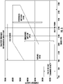
FIG. 6 is a graphical illustration of a performance of the TRU system operated according to the method ofFIG. 5 . - As will be described below, a refrigeration compressor drive frequency is decoupled from a primary diesel generator frequency using a refrigeration compressor variable speed AC inverter that is located between a 3-phase diesel synchronous generator and the compressor. The approach will be to allow the engine to run at lowest possible engine speeds for needed power while allowing the refrigeration system to vary operations of the primary compressor and if needed fan speeds based on capacity demands. As refrigeration power demand increases, the engine can stay in a lowest speed required to match torque demanded from the compressor and fan systems with intent of staying in lowest speed required to match demand of the refrigeration or compressor system. If engine power is approaching a maximum available power, the engine will increase in rpm to thereby increase available engine power to thus supply the AC inverter with power needed for the refrigeration compressor.
- With reference to
FIGS. 1 and 2 , a truck ortrailer 101 is provided and includes avehicle portion 110, atrailer portion 120 and a TRU 130. Thevehicle portion 110 includes acabin 111, which is supportive of an engine 112 and which is configured to accommodate an operator and one or more passengers, and abed 113 in the rear of thecabin 111. In some cases, the engine 112 can be provided as a diesel engine or another similar type of internal combustion engine. For clarity and brevity, the following description will relate to the case of the engine 112 being an internal combustion diesel engine. Thetrailer portion 120 can be seated on thebed 113 and has abody 121 that is formed to define aninterior 122 in which items being transported or shipped can be stored. The TRU 130 is operably coupled directly or indirectly to and is configured to be seated upon thebody 121 of thetrailer portion 120. - The TRU can include an engine and is configured to generate a cooling (or heating) airflow that can be directed into the
interior 122 so as to control at least a temperature of theinterior 122. In this way, in an exemplary case in which the items being transported are perishable and need to be refrigerated (or heated), the TRU 130 can maintain theinterior 122 in a refrigerated (or heated) state even during hot (or cold) days. - As shown in
FIG. 2 , the TRU 130 can be operated according to avapor compression cycle 200 and includes acompressor 131, acondenser 132, anexpansion valve 133, anevaporator 134 andfans compressor 131 compresses vapor and outputs the compressed vapor to thecondenser 132. Within thecondenser 132, the compressed vapor is condensed into a liquid, while thefan 136 blows air over and through thecondenser 132, which is directed to theexpansion valve 133. The liquid is expanded through theexpansion valve 133 into a mixture of liquid and vapor that is directed to theevaporator 134. The mixture of liquid and vapor then flows through coils of theevaporator 134 while thefan 135 blows air (i.e., warm air) over the coils whereupon the liquid removes heat from the air and turns into vapor. This cools the air so that the air can be directed into theinterior 122 as cooled air. The vapor is then flown into thecompressor 131. - With continued reference to
FIGS. 1 and 2 and with additional reference toFIGS. 3 and 4 , aTRU system 301 is provided for handling certain operations of the TRU 130 ofFIGS. 1 and 2 . The TRUsystem 301 can include anonboard engine 302 or, in some cases, can be directly or indirectly connected to another engine, such as the engine 112 ofFIG. 1 . The following description will relate to the cases in which theengine 302 is an onboard engine of theTRU system 301. - The
TRU system 301 further includes agenerator 310, an alternating current (AC) inverter 320 and avariable speed compressor 330. The TRUsystem 301 further includes an air management system 340 (seeFIG. 3 ) and/or parallelair management systems 401 and 402 (seeFIG. 4 ). Thegenerator 310 can include or be provided as a 3-phase diesel synchronous generator. Thegenerator 310 can be directly or indirectly driven by theengine 302 to generate electricity and power for use by thevariable speed compressor 330 and theair management system 340 ofFIG. 3 and/or the parallelair management systems FIG. 4 . TheAC inverter 320 can include or be provided as a refrigeration compressor variable speed AC inverter. The air management system (e.g., the parallelair management system 401 and 402) can include or be provided as one or more fan motor AC inverter(s) 412, 421 (i.e., for driving thefans FIG. 2 ). The air management system (i.e., when configured as a parallelair management system 401 and 402) may include an evaporatorair management system 411 in series with the fan motor AC inverter 410, and a condenserair management system 421 in series with the fan motor AC inverter 420. - The
TRU system 301 ofFIGS. 3 and 4 are thus characterized in that the refrigeration compressor drive frequency of at least thevariable speed compressor 330 is decoupled from the primary diesel generator frequency of thegenerator 310 using theAC inverter 320 which is located or operably disposed between thegenerator 310 and thevariable speed compressor 330. TheTRU system 301 allows theengine 302 to run at a lowest possible engine speed for needed power while varying compressor and fan speeds based on capacity demand. As refrigeration power demand increases, theengine 302 can stay in a lowest speed that is required to match torque demanded from thecompressor 131 and thefans engine 302 will increase in rpm to thus increase available engine power and to supply theAC inverter 320 with sufficient power as needed for thecompressor 131 and thefans - With continued reference to
FIGS. 1-4 and with additional reference toFIG. 5 , a method or scheme of operation of a TRU system, such as theTRU system 301 ofFIGS. 3 and 4 , is provided in accordance with embodiments. As shown inFIG. 5 , the method or scheme includes aTRU control 501 that considers whether theengine 302 is within a desired load range forTRU control 502 as well as additional issues arising therefrom and whether a TRU temperature error is greater than zero 503 (i.e., whether a temperature within theinterior 122 is at a target temperature or not) as well as additional issues arising therefrom. - If the
engine 302 is within the desired load range for the TRU control, engine rpm is maintained 504. Conversely, if theengine 302 is not within the desired load range for the TRU control, it is determined whether more engine power is required from the TRU control 505 (see a determination of whether more engine power is requested atblock 513 to be discussed below). If more engine power is not required, engine power is reduced 506 and engine rpm is decreased 507 and control reverts to considering whether theengine 302 is within a desired load range forTRU control 502. If more engine power is required, engine rpm is increased 508 and control reverts to considering whether theengine 302 is within a desired load range forTRU control 502. - If the TRU temperature error is not greater than zero, it is determined whether TRU temperature error equals zero 509. If the TRU temperature error does not equal zero, a compressor drive frequency of the
compressor 131 is decreased 510 and control reverts to determining whether the TRU temperature error is greater than zero 503. If the TRU temperature error equals zero, the compressor drive frequency is maintained 511 and control reverts to determining whether the TRU temperature error is greater than zero 503. - If the TRU temperature error is greater than zero, it is determined whether engine load is greater than a
maximum load range 512. If the engine load is greater than the maximum load range, the compressor drive frequency is decreased 510 and control reverts to determining whether the TRU temperature error is greater than zero 503. If the engine load is not greater than the maximum load range, more engine power is requested 513 and it is determined whether engine power has been increased to adesirable load range 514. If the engine power has not been increased to the desirable load range, the compressor drive frequency is maintained 511 and control reverts to determining whether the TRU temperature error is greater than zero 503. If the engine power has been increased to the desirable load range, it is determined whether thecompressor 131 is at amaximum drive frequency 515. If thecompressor 131 is at the maximum drive frequency, the compressor drive frequency is maintained 511 and control reverts to determining whether the TRU temperature error is greater than zero 503. If thecompressor 131 is not at the maximum drive frequency, the compressor drive frequency is increased 516 and control reverts to determining whether the TRU temperature error is greater than zero 503. - With reference to
FIG. 6 , a performance of theTRU system 301 ofFIGS. 3 and 4 and operated according to the method or scheme ofFIG. 5 is illustrated graphically. As shown inFIG. 6 it is apparent that an operational capability of thecompressor 131 is greatly increased from low engine rpm to high engine rpm and from low compressor capacity to high compressor capacity resulting from the use of a variable speed compressor as compared to synchronous units. - Technical effects and benefits of the present disclosure are the provision of systems in which compressor operations are decoupled from primary diesel engine speed to thereby allow for maximized fuel efficiency gains arising from compressor capacity maximizations as needed with lowest possible engine speeds. The systems allow for maximum total efficiency BTUs/ lb_fuel as well as 75% of TRU run time in low-power conditions, which will allow for low fuel burn rates and reduced noise. The systems also allow for engines to run at peak torque for maximized refrigeration load as needed as well as smaller and less costly TRU engines with wide speed ranges of about 600-2500 rpm for example. Use of the systems can provide for cases in which high engine speeds would only be needed for short durations characterized by high power demand associated with high ambient conditions.
- The corresponding structures, materials, acts, and equivalents of all means or step-plus function elements in the claims below are intended to include any structure, material, or act for performing the function in combination with other claimed elements as specifically claimed. The description of the present disclosure has been presented for purposes of illustration and description, but is not intended to be exhaustive or limited to the technical concepts in the form disclosed. Many modifications and variations will be apparent to those of ordinary skill in the art without departing from the scope of the invention as set out on the appended claims. The embodiments were chosen and described in order to best explain the principles of the invention and the practical application, and to enable others of ordinary skill in the art to understand the invention for various embodiments with various modifications as are suited to the particular use contemplated.
- While the preferred embodiments of the invention have been described, it will be understood that those skilled in the art, both now and in the future, may make various improvements and enhancements which fall within the scope of the claims which follow. These claims should be construed to maintain the proper protection for the invention.
- The following clauses set out aspects of the invention which may or may not be presently claimed but which may form basis for future amendments and/or a divisional application.
- 1. A method of operating a transport refrigeration unit (TRU) system comprising an air management system, a compressor, a generator which generates alternating current (AC) from operations of an engine to power operations of the air management system and the compressor and an AC inverter operably interposed between the generator and the compressor, the method comprising:
decoupling a drive frequency of the compressor from a frequency of the generator. - 2. The method according to clause 1, wherein the decoupling of the drive frequency of the compressor from the frequency of the generator comprises:
- operating the compressor at a variable speed to meet a demand;
- operating an engine at a lowest possible speed to provide power for the compressor;
- maintaining operations of the engine at the lowest possible speed as the demand increases; and
- increasing an engine speed of the engine as available power of the engine approaches a maximum.
Claims (15)
- A transport refrigeration (TRU) system (301), comprising:an air management system (340);a compressor (330);a generator (310) which generates alternating current (AC) from operations of an engine (302) to power operations of the air management system (340) and the compressor (330); andan AC inverter (412, 421) operably interposed between the generator (310) and the compressor (330) to decouple a drive frequency of the compressor (330) from a frequency of the generator (310).
- The TRU system (301) according to claim 1, wherein the compressor (330) comprises a variable speed compressor.
- The TRU system (301) according to claim 1 or 2, wherein the air management system comprises parallel air management systems (401, 402).
- The TRU system (301) according to any preceding claim, wherein the engine (302) is run at a lowest possible engine speed for needed power and compressor speed is varied based on capacity demand;optionally, wherein the engine (302) continues to run at the lowest possible engine speed as the capacity demand increases to match a torque demanded from the compressor (330); andfurther optionally, wherein engine speed increases as the engine (302) approaches a maximum available power.
- A method of operating the transport refrigeration unit (TRU) system (301) of any preceding claim, the method comprising:
decoupling a drive frequency of the compressor (330) from a frequency of the generator (310);
optionally, wherein the decoupling of the drive frequency of the compressor (330) from the frequency of the generator (310) comprises:operating the compressor (330) at a variable speed to meet a demand;operating an engine (302) at a lowest possible speed to provide power for the compressor (330);maintaining operations of the engine (302) at the lowest possible speed as the demand increases; andincreasing an engine speed of the engine (302) as available power of the engine approaches a maximum. - A method of operating a transport refrigeration unit (TRU) system (301) in which a drive frequency of a compressor (330) is decoupled from a frequency of a generator (310), the method comprising:operating the compressor (330) at a variable speed to meet a demand;operating an engine (302) at a lowest possible speed to provide power for the compressor (330);maintaining operations of the engine (302) at the lowest possible speed as the demand increases; andincreasing an engine speed of the engine (302) as available power of the engine approaches a maximum.
- The method according to claim 6, wherein the operating of the engine (302) comprises determining whether the engine (302) is operating within a desired load range.
- The method according to claim 7, wherein the operating of the engine (302) further comprises:maintaining an engine speed if the engine (302) is operating within the desired load range; and/orincreasing an engine speed if the engine (302) is not operating within the desired load range and more engine power is required; and/orreducing engine power and decreasing engine speed if the engine (302) is not operating within the desired load range and more engine power is not required.
- The method according to any of claims 6 to 8, wherein the operating of the compressor (330) comprises determining whether a TRU temperature error is greater than zero.
- The method according to claim 9, wherein the operating of the compressor (330) further comprises decreasing a compressor drive frequency if the TRU temperature error is not greater than zero and not equal to zero.
- The method according to claim 9, wherein the operating of the compressor (330) further comprises decreasing a compressor drive frequency if the TRU temperature error is greater than zero and an engine load is greater than a maximum load range.
- The method according to claim 9, wherein the operating of the compressor further comprises maintaining the compressor drive frequency if the TRU temperature error is not greater than zero and is equal to zero.
- The method according to claim 9, wherein the operating of the compressor further comprises maintaining the compressor drive frequency if the TRU temperature error is greater than zero and if the engine load is not greater than a maximum load range, more engine power has been requested and engine power has not been increased.
- The method according to claim 9, wherein the operating of the compressor further comprises maintaining the compressor drive frequency if the TRU temperature error is greater than zero and if the engine load is not greater than a maximum load range, more engine power has been requested, engine power has been increased and the compressor is at a maximum drive frequency.
- The method according to claim 9, wherein the operating of the compressor further comprises increasing a compressor drive frequency if the TRU temperature error is greater than zero and if the engine load is not greater than a maximum load range, more engine power has been requested, engine power has been increased and the compressor is not at a maximum drive frequency.
Applications Claiming Priority (1)
| Application Number | Priority Date | Filing Date | Title |
|---|---|---|---|
| US202063115909P | 2020-11-19 | 2020-11-19 |
Publications (1)
| Publication Number | Publication Date |
|---|---|
| EP4000976A1 true EP4000976A1 (en) | 2022-05-25 |
Family
ID=78371871
Family Applications (1)
| Application Number | Title | Priority Date | Filing Date |
|---|---|---|---|
| EP21204031.5A Withdrawn EP4000976A1 (en) | 2020-11-19 | 2021-10-21 | Transport refrigeration unit with variable-speed electric refrigeration drive and variable-speed diesel engine synchronous generator power source |
Country Status (3)
| Country | Link |
|---|---|
| US (1) | US20220153090A1 (en) |
| EP (1) | EP4000976A1 (en) |
| CN (1) | CN114537077A (en) |
Citations (5)
| Publication number | Priority date | Publication date | Assignee | Title |
|---|---|---|---|---|
| JPH07172157A (en) * | 1993-12-20 | 1995-07-11 | Sanden Corp | Controller of air conditioner for vehicle |
| US20120167605A1 (en) * | 2009-09-16 | 2012-07-05 | Makoto Ikemiya | Container refrigeration system |
| US9194286B2 (en) * | 2012-03-23 | 2015-11-24 | Thermo King Corporation | Control system for a transport refrigeration system |
| US9718328B2 (en) * | 2014-10-28 | 2017-08-01 | Denso Corporation | Engine control apparatus |
| US20180222278A1 (en) * | 2014-09-09 | 2018-08-09 | Denso Corporation | Refrigeration device and container refrigeration system |
Family Cites Families (5)
| Publication number | Priority date | Publication date | Assignee | Title |
|---|---|---|---|---|
| JP2007113874A (en) * | 2005-10-21 | 2007-05-10 | Daikin Ind Ltd | Freezer for trailer |
| US20090056354A1 (en) * | 2007-08-30 | 2009-03-05 | Scott Judson Davis | Refrigeration power system for a storage compartment in a vehicle |
| CN102203515A (en) * | 2008-10-31 | 2011-09-28 | 开利公司 | Control of multiple zone refrigerant vapor compression systems |
| EP3634792B1 (en) * | 2017-06-07 | 2024-10-23 | Carrier Corporation | Hybrid power conversion system for a refrigerated transport vehicle and method |
| EP4480726B1 (en) * | 2018-10-11 | 2026-04-29 | Carrier Corporation | Variable speed for transport engineless refrigeration unit |
-
2021
- 2021-10-21 EP EP21204031.5A patent/EP4000976A1/en not_active Withdrawn
- 2021-11-11 US US17/524,669 patent/US20220153090A1/en not_active Abandoned
- 2021-11-18 CN CN202111367587.6A patent/CN114537077A/en active Pending
Patent Citations (5)
| Publication number | Priority date | Publication date | Assignee | Title |
|---|---|---|---|---|
| JPH07172157A (en) * | 1993-12-20 | 1995-07-11 | Sanden Corp | Controller of air conditioner for vehicle |
| US20120167605A1 (en) * | 2009-09-16 | 2012-07-05 | Makoto Ikemiya | Container refrigeration system |
| US9194286B2 (en) * | 2012-03-23 | 2015-11-24 | Thermo King Corporation | Control system for a transport refrigeration system |
| US20180222278A1 (en) * | 2014-09-09 | 2018-08-09 | Denso Corporation | Refrigeration device and container refrigeration system |
| US9718328B2 (en) * | 2014-10-28 | 2017-08-01 | Denso Corporation | Engine control apparatus |
Also Published As
| Publication number | Publication date |
|---|---|
| US20220153090A1 (en) | 2022-05-19 |
| CN114537077A (en) | 2022-05-27 |
Similar Documents
| Publication | Publication Date | Title |
|---|---|---|
| EP2844506B1 (en) | Transport refrigeration system having electric fans | |
| US20190255906A1 (en) | High voltage system for a transport refrigeration unit | |
| EP3440417B1 (en) | Transport refrigeration unit | |
| EP2897824B1 (en) | Electrical transport refrigeration system | |
| US7845187B2 (en) | Thermal management system and method for automotive vehicle | |
| US11707962B2 (en) | Trailer transport refrigeration unit assisted by a tractor auxiliary power unit | |
| US20190105969A1 (en) | Transport refrigeration unit | |
| US20190120530A1 (en) | Transport refrigeration unit with battery boost | |
| EP3193104A1 (en) | Refrigerating device and container refrigerating system | |
| US20110110791A1 (en) | Continuous compressor envelope protection | |
| US20150292784A1 (en) | Organic rankine cycle augmented power supply system for mobile refrigeration units | |
| US11235641B2 (en) | Thermal system control for a vehicle | |
| CN116923043B (en) | Integrated thermal management system and vehicle | |
| EP1598225A2 (en) | Energy efficient capacity control for an air conditioning system | |
| CN113752778A (en) | Thermal system control for a vehicle | |
| KR20200069963A (en) | Multiple compressor cooling system for refrigerated vehicle | |
| US20220153090A1 (en) | Transport refrigeration unit with variable-speed electric refrigeration drive and variable-speed diesel engine synchronous generator power source | |
| KR101186467B1 (en) | Power control apparatus of vehicle for transporting frozen, refrigerated and warmed foods and method thereof | |
| US12030368B2 (en) | Compressor systems and methods for use by vehicle heating, ventilating, and air conditioning systems | |
| US11673449B2 (en) | Method and system for control of a hybrid power system for powering a transport climate control system | |
| KR20090083543A (en) | Refrigeration equipment for refrigeration vehicles with a high power generator | |
| CN119953144B (en) | An integrated refrigeration system and method | |
| US20100026011A1 (en) | Expansion Circuit | |
| JP2013002803A (en) | Refrigerating device for trailer |
Legal Events
| Date | Code | Title | Description |
|---|---|---|---|
| PUAI | Public reference made under article 153(3) epc to a published international application that has entered the european phase |
Free format text: ORIGINAL CODE: 0009012 |
|
| STAA | Information on the status of an ep patent application or granted ep patent |
Free format text: STATUS: THE APPLICATION HAS BEEN PUBLISHED |
|
| AK | Designated contracting states |
Kind code of ref document: A1 Designated state(s): AL AT BE BG CH CY CZ DE DK EE ES FI FR GB GR HR HU IE IS IT LI LT LU LV MC MK MT NL NO PL PT RO RS SE SI SK SM TR |
|
| STAA | Information on the status of an ep patent application or granted ep patent |
Free format text: STATUS: REQUEST FOR EXAMINATION WAS MADE |
|
| 17P | Request for examination filed |
Effective date: 20221125 |
|
| RBV | Designated contracting states (corrected) |
Designated state(s): AL AT BE BG CH CY CZ DE DK EE ES FI FR GB GR HR HU IE IS IT LI LT LU LV MC MK MT NL NO PL PT RO RS SE SI SK SM TR |
|
| STAA | Information on the status of an ep patent application or granted ep patent |
Free format text: STATUS: EXAMINATION IS IN PROGRESS |
|
| 17Q | First examination report despatched |
Effective date: 20230404 |
|
| STAA | Information on the status of an ep patent application or granted ep patent |
Free format text: STATUS: THE APPLICATION HAS BEEN WITHDRAWN |
|
| 18W | Application withdrawn |
Effective date: 20230811 |